MUTO Premium Accessory - Accessory Dormakaba - Free user manual and instructions
Find the device manual for free MUTO Premium Accessory Dormakaba in PDF.


| Product Type | Electromagnetic Lock Accessory (MUTO Premium Accessory) |
| Compatible Systems | MUTO PREMIUM sliding door systems XL150, XL80, XL120 |
| Max Door Leaf Weight (XL150/80) | ≤ 330 lbs (≤ 150 kg) |
| Max Door Leaf Weight (XL120) | ≤ 264 lbs (≤ 120 kg) |
| Power Input | 12 VDC, 1 A max |
| Alarm Relay Output | 30 VDC, 2 A max / 120 VAC, 1 A max |
| Early Warning (EW) Sensor | Integrated; timer adjustable 0-30 sec |
| Locking Force | Not specified in manual; typical for MEM4400: 1200 lbs (544 kg) |
| Dimensions (Mag Lock) | Refer to Fig. 1 in manual (not to scale); typical: 6.1 x 1.6 x 1.0 in (155 x 41 x 25 mm) |
| Glass Thickness Requirement | Tempered monolithic or laminated; clamping area flat and uncoated |
| Mounting | Wall or ceiling mount; for dry indoor areas only |
| Handing Changeable | Yes, via adjustable armature bracket |
| Wiring | Connect to PCB: power input, exit input, DSS sensor, MEM lock output, alarm relay, timer |
| Safety Instructions | Installation by qualified personnel; use protective gloves/goggles; electric shock warning |
| Maintenance | Clean with damp cloth; use silicone- and oil-free cleaners; check periodically |
| Repair | Replace damaged parts with original dormakaba parts only |
| Disposal | Follow local, state, and national regulations |
| Temperature Range (Indoor) | 32°F to 122°F (0°C to 50°C) typical |
| Compliance | UL standard? Not specified; for commercial use |
Frequently Asked Questions - MUTO Premium Accessory Dormakaba
User questions about MUTO Premium Accessory Dormakaba
0 question about this device. Answer the ones you know or ask your own.
Ask a new question about this device
Download the instructions for your Accessory in PDF format for free! Find your manual MUTO Premium Accessory - Dormakaba and take your electronic device back in hand. On this page are published all the documents necessary for the use of your device. MUTO Premium Accessory by Dormakaba.
USER MANUAL MUTO Premium Accessory Dormakaba
Muto Electro Magnetic Lock (Elock MEM4400)
Installation instructions / Wiring manual
936033 - 08-2021
| EN |
Table of contents
1 Technical specifications 3
1.1 Overview 3
1.1.1 General information 3
1.1.2 Intended use 3
1.1.3 Glass requirements and fittings 3
1.1.4 Requirements for glass panel 3
1.1.5 Safety instructions 3
1.1.6 Symbols used - Safety/Installation 3
1.1.7 Maintenance, care, repair 3
1.1.8 Disposal 3
1.2 Specifications - technical data 4
1.3 Dimensions 4
2 Installation instructions 4
2.1 Overall 4
2.2 Secure armature bracket to rollers:
to glass or wood doors 5
2.3 Secure terminal block to door frame 6
2.4 Secure mag lock to wall/door frame structure 6
3 Change handing of mag lock 7
3.1 Change handing 7
4 Wiring the circuit board 8
4.1 Wiring diagram 8
1 Technical specifications
1.1 Overview
These instructions are for installation of MUTO PREMIUM sliding door system XL150 / XL80 / XL120 for the following mounting and style versions:
1. Wall or Ceiling mount
1.1.1 General information
- dormakaba requires use of tempered monolithic or tempered laminated glass.
- dormakaba glass hardware is not suitable for application in rooms where chemicals (e.g. chlorine) are used as indoor swimming pools, saunas or salt-water pools.
- Never move sliding panels faster than walking speed and always stop the door manually before it reaches end position.
- Do not slide doors with excessive force. Install limiting stop to prevent door from opening too far.
1.1.2 Intended use
- For sliding door in dry indoor areas only
- For manual slowly opening and closing only
1.1.3 Glass requirements and fittings
- The substructure/wall must be able to bear permanent loads and be level (max. tolerance: 1/16" [2] per 39" [1m]).
- Fasteners must be sufficiently dimensioned for the substructure/wall and weight of the door.
- When adjusting glass components, always stick to the required clearance for the respective hardware. Adjust clearance so glass does not come in contact with any hard surfaces such as glass, metal or concrete.
- Do not use excessive force when installing the glass (avoid over tightening screws).
1.1.4 Requirements for glass panel
- dormakaba requires use of fully tempered glass, which complies with ASTM C 1036 and ASTM C 1048. Secondary heat soaking processes are optional but not required. This applies to both tempered monolithic and tempered laminated glass.
- Clamping area must be flat and uncoated (no self-cleaning coating!)
- Never use glass with conchoidal fractures and/or damaged edges.
1.1.5 Safety instructions
• Installation requires two people.
- Only properly qualified and specially trained staff are authorized to mount dormakaba glass hardware.
- Due to crushing hazards and possible injury caused by breakage of glass during mounting, corresponding protective clothing (especially gloves and protective goggles) is required.
• Work on electrical equipment and 240/120 VAC wiring installation must be performed ONLY by qualified personnel.
1.1.6 Symbols used - Safety/Installation

CAUTION
Mounting components must meet the requirements of substructure/wall and door weight. Please read the technical information for fittings.

WARNING
Risk of breaking glass. When installing the door, support the door panel with a block of wood or similar object.

WARNING
Electric shock warning!

CLOSING EDGE
1.1.7 Maintenance, care, repair
- Immediately replace damaged parts.
• Always use original dormakaba parts. - Clean clamping area with alcohol-based standard commercial cleaning agent before mounting the glass hardware.
- Use a damp clothe for occasional cleaning, especially the track.
• Always use silicone - and oil-free cleaners (e.g. acetone). - Check glass hardware at regular intervals for proper positioning and smooth operation and correct adjustment.
- High traffic door systems require inspection by properly qualified staff (specialized companies or installation firms.)
1.1.8 Disposal
Disposal in accordance with local, state and national regulations.
1.2 Specifications - technical data
| Single Door Single Door | ||
| XL150/80 XL120 | ||
| Wall or Ceiling mount | Door leaf weight lbs [kg] * ≤330lbs[≤150] | ≤264lbs[≤120] |
| * Including weight of auxiliary hardware. | ||
1.3 Dimensions
Fig. 1
NOT TO SCALE
![For all MUTO XL150 less DM only applications 2" [48]](/content/2026/05/828234/images/e7e7bb082b1f327b8e637b1c70e178257cc91b670d473643669e9c217d886276.jpg)
![For MUTO XL120 SC only applications 2-11/16" [68]](/content/2026/05/828234/images/ea57a87875d57e4b73d4178d6fbb2617a1e45046a63b7240b6a6e7ee981efb81.jpg)
![For MUTO XL150/80 DM only applications 3-1/2" [88]](/content/2026/05/828234/images/2ad25b6044dbe65568cb790a08d17be76bf357a6b2489571d692725978c359b4.jpg)
2 Installation instructions
2.1 Overall
Fig. 2

1.1 MEM4400 mag lock
1.2 Circuit board
1.3 Armature
1.4 Armature bracket
2.2 Secure armature bracket to rollers: to glass or wood doors
Fig. 3
![Glass cut out: pre-fab Glass panel Wood Door Adaptor cut out: TO BE CUT IN FIELD 1-1/16" [27] Wood door adaptor Wood door Armature Armature bracket Leading roller carrier Armature bracket screw slots NOTE: Ensure armature and bracket align with mag lock, once installed. • Use any of the 3 screw slots in bracket to mount accordingly. Mag lock](/content/2026/05/828234/images/8ebee3c076ebf6742c5e4ded8db0adfa47361ddf7bfe8fb244f9753e214ee601.jpg)
2.2.1 Glass door: Ensure glass cut out is toward the closing side of the moving panel.
2.2.2 Wood door: Cut 1-1/16" [27] from leading end of wood door adaptor.
2.2.3 Secure armature bracket to leading roller carrier.
- Use included fasteners.
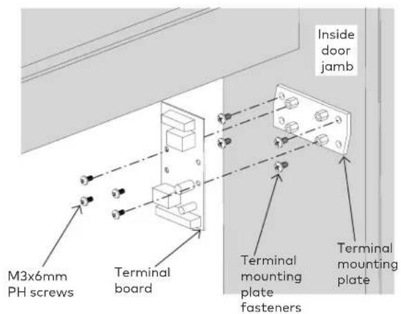
2.3 Secure terminal block to door frame
Fig. 4
MUTO SYSTEM HIDDEN FOR EASIER VIEWING
2.3.1 Secure terminal mounting plate to a concealed location in close vaccinity to mag lock. (preferably in jamb or above ceiling)
• Use pre-attached fasteners (x4).
2.3.2 Secure terminal board to mountg plate.
• Use included M3x6mm PH Phillips screws (x4).
2.4 Secure mag lock to wall/door frame structure
Fig. 5
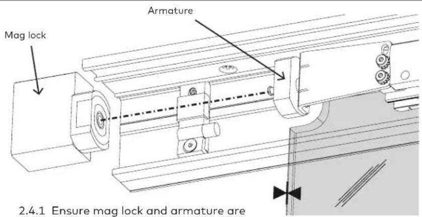
2.4.1 Ensure mag lock and armature are properly aligned.
![1/8" [2.7] Mag lock MUTO track 5/8" [15.4] 23/32" [18.4] Side elevation view of mag lock](/content/2026/05/828234/images/fa682afa8aa796383062c2cd9d88cd01de1d98e6292898298c058b47ae4adaef.jpg)

![2" [50] Side panel 1-3/16" [30]](/content/2026/05/828234/images/a1cc6735d3e65a9b35e489244d74bf23126cfff03a208ce4953b9ffb4b3058a9.jpg)
2.4.2 Remove side panel from mag lock.

2.4.3 Secure mag lock onto wall/door frame structure through any of the holes in the mag lock, as required per your application.
![(Blocking by others) (Blocking by others) 1-1/2" [38] Mag lock MUTO Track Armature](/content/2026/05/828234/images/9ce31379f261b3cb71579d51263ab1065a8d312ea8b033ff89acc89f4c182ada.jpg)
- Use appropriate fasteners (not included).
3 Change handing of mag lock
3.1 Change handing
Fig. 6

![Screw [inside armature]](/content/2026/05/828234/images/ac393cfcbd6a39245694f0e3faa37755e9cf4f12551949be466553bda92a07ed.jpg)
To change to another size bracket:
3.1.1 Press spanner wrench into holes in the end of the armature and partially rotate circular plate.
![Nut Screw [inside armature]](/content/2026/05/828234/images/6fe2e7e8ae5d42a94202530b8e3cad903a305937fc110177d5c1968193032209.jpg)
3.1.2 Remove circular plate to access screw inside armature.

3.1.3 Hold nut in place, and unthread/loosen screw from inside armature.
- NOTE: The screw does NOT need to be fully removed.
3.1.4 Pull the armature away from the bracket to disengage the two pins.
3.1.5 Rotate armature bracket in correct direction depending upon your application, until the two pins reengage in the bracket.

![Screw [inside armature] Circular plate with holes](/content/2026/05/828234/images/80ce4a850f6aae708e19b989c6ecba14364eff60378e8381e49e000fcfbd581c.jpg)
3.1.6 Hold nut in place, and tighten screw inside the armature.
3.1.7 Place circular plate back into end of armature.
3.1.8 Rotate, with spanner wrench, to lock into place.
4 Wiring the circuit board
4.1 Wiring diagram
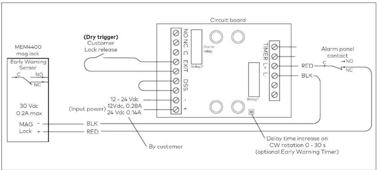
MEM Lock Wirng to PCB Wire color
| MEM Power Input, 12VDC | Black (-) | Connects to Power Input |
| Red (+) | ||
| EW Sensor Output(EW = Early Warning) | Brown (C) | Connects to DSS if usedWhite (NC) |
| Grey (NO) | ||
| PCB Connection Terminal Designation | ||
| Power Input | - | +12 VDC, 1A maximum |
| + | ||
| Exit Input EXIT Connects to customer dry trigger | ||
| DSS Sensor Input DSS Use jumper or Early Warning Sensor brown and white wires | ||
| MEM Lock Power Output | L- (BLK) | Connect to Mag Lock |
| L+ (RED) | ||
| Alarm Relay Output30 VDC, 2A max.120 VAC, 1A max. | NO | Use to trigger auxiliary LED, siren, alarm panel, etc.NC |
| C | ||
| Alarm Relay Timer Input TIMER | 0 to 30 sec. delay timer (EW)Contact closes to activate Alarm Relay OutputUse to trigger alarm panel or other. | |
- Muto Electro Magnetic Lock (Elock MEM4400)
- Table of contents
- Technical specifications 3
- Installation instructions 4
- Technical specifications
- Overview
- Wall or Ceiling mount
- General information
- Intended use
- Glass requirements and fittings
- Requirements for glass panel
- Safety instructions
- Symbols used - Safety/Installation
- CAUTION
- WARNING
- CLOSING EDGE
- Maintenance, care, repair
- Disposal
- Specifications - technical data
- Dimensions
- Installation instructions
- Overall
- Secure armature bracket to rollers: to glass or wood doors
- Secure terminal block to door frame
- MUTO SYSTEM HIDDEN FOR EASIER VIEWING
- Secure mag lock to wall/door frame structure
- Change handing of mag lock
- Change handing
- To change to another size bracket:
- Wiring the circuit board
- Wiring diagram
Brand : Dormakaba
Model : MUTO Premium Accessory
Category : Accessory