
PN-HW501T - Whiteboard SHARP - Free user manual and instructions
Find the device manual for free PN-HW501T SHARP in PDF.

| Product Type | Interactive Whiteboard / LCD Color Monitor |
| Model | PN-HW501T |
| Display Type | TFT Color LCD with LED Backlight |
| Resolution | 3840 x 2160 (4K UHD) |
| Brightness | 500 cd/m² (typical) |
| Contrast Ratio | 1000:1 (typical) |
| Viewing Angle | 178° horizontal / 178° vertical |
| Connectivity | 3x HDMI, 1x D-Sub, 1x USB, 1x RS-232C, 1x LAN, Audio Input, Audio Output, IR Output |
| Built-in Speakers | Yes |
| Power Supply | AC 100-240V, 50/60Hz |
| Power Consumption | 150W (typical) |
| Standby Power Consumption | Less than 0.5W (with Power Save Mode) |
| Weight | Approx. 25 kg (55 lbs) |
| Dimensions (W x H x D) | Approx. 1120 x 650 x 60 mm (44.1 x 25.6 x 2.4 in) |
| VESA Mount Pattern | 400 x 400 mm (M6 screws) |
| Operating Temperature | 32°F to 104°F (0°C to 40°C) |
| Storage Temperature | -4°F to 140°F (-20°C to 60°C) |
| Media Player Support | USB flash drive: photo (JPEG), music (MP3), video (TS, MP4 up to Full HD) |
| Remote Control | Yes, with AAA batteries |
| Accessories Included | Remote control, batteries, power cord, CD-ROM, setup manual, cable clamps, logo sticker, USB flash drive cover |
Frequently Asked Questions - PN-HW501T SHARP
User questions about PN-HW501T SHARP
0 question about this device. Answer the ones you know or ask your own.
Ask a new question about this device
Download the instructions for your Whiteboard in PDF format for free! Find your manual PN-HW501T - SHARP and take your electronic device back in hand. On this page are published all the documents necessary for the use of your device. PN-HW501T by SHARP.
USER MANUAL PN-HW501T SHARP
Information on the Disposal of this Equipment and its Batteries
IF YOU WISH TO DISPOSE OF THIS EQUIPMENT OR ITS BATTERIES, DO NOT USE THE ORDINARY WASTE BIN, AND DO NOT PUT THEM INTO A FIREPLACE!
Used electrical and electronic equipment and batteries should always be collected and treated SEPARATELY in accordance with local law.
Separate collection promotes an environment-friendly treatment, recycling of materials, and minimizing final disposal of waste. IMPROPER DISPOSAL can be harmful to human health and the environment due to certain substances! Take USED EQUIPMENT to a local, usually municipal, collection facility, where available.
Remove USED BATTERIES from equipment, and take them to a battery collection facility; usually a place where new batteries are sold.
If in doubt about disposal, contact your local authorities or dealer and ask for the correct method of disposal.
ONLY FOR USERS IN THE EUROPEAN UNION, AND SOME OTHER COUNTRIES; FOR INSTANCE NORWAY AND SWITZERLAND: Your participation in separate collection is requested by law.
The symbol shown above appears on electrical and electronic equipment and batteries (or the packaging) to remind users of this. If 'Hg' or 'Pb' appears below the symbol, this means that the battery contains traces of mercury (Hg) or lead (Pb), respectively.
Users from PRIVATE HOUSEHOLDS are requested to use existing return facilities for used equipment and batteries. Batteries are collected at points of sale. Return is free of charge.
If the equipment has been used for BUSINESS PURPOSES, please contact your SHARP dealer who will inform you about take-back. You might be charged for the costs arising from take-back. Small equipment (and small quantities) might be taken back by your local collection facility. For Spain: Please contact the established collection system or your local authority for take-back of your used products.
WARNING: TO REDUCE THE RISK OF FIRE OR ELECTRIC SHOCK, DO NOT EXPOSE THIS PRODUCT TO RAIN OR MOISTURE.
CAUTION
RISK OF ELECTRIC SHOCK DO NOT OPEN

CAUTION: TO REDUCE THE RISK OF ELECTRIC SHOCK, DO NOT REMOVE COVER. NO USER-SERVICEABLE PARTS INSIDE. REFER SERVICING TO QUALIFIED SERVICE PERSONNEL.

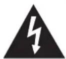
The lightning flash with arrowhead symbol, within a triangle, is intended to alert the user to the presence of uninsulated “dangerous voltage” within the product’s enclosure that may be of sufficient magnitude to constitute a risk of electric shock to persons.

The exclamation point within a triangle is intended to alert the user to the presence of important operating and maintenance (servicing) instructions in the literature accompanying the product.
[PN-HW861/PN-HW751/PN-HW651]
FOR CUSTOMERS IN U.K.
IMPORTANT
The wires in this mains lead are coloured in accordance with the following code:
GREEN-AND-YELLOW:
Earth
BLUE:
Neutral
BROWN:
Live
As the colours of the wires in the mains lead of this apparatus may not correspond with the coloured markings identifying the terminals in your plug proceed as follows:
- The wire which is coloured GREEN-AND-YELLOW must be connected to the terminal in the plug which is marked by the letter E or by the safety earth 12 or coloured green or green-and-yellow.
- The wire which is coloured BLUE must be connected to the terminal which is marked with the letter N or coloured black.
• The wire which is coloured BROWN must be connected to the terminal which is marked with the letter L or coloured red.
Ensure that your equipment is connected correctly. If you are in any doubt consult a qualified electrician.
"WARNING: THIS APPARATUS MUST BE EARTHED."
[PN-HW551/PN-HW501/PN-HW431]
NOTE FOR USERS IN U.K.
IMPORTANT
The wires in this mains lead are coloured in accordance with the following code:
BLUE: "NEUTRAL"
BROWN: "LIVE"
CONNECTING PLUG TO MAINS LEAD:
As the colours of the wires in the mains lead of this apparatus may not correspond with the coloured markings identifying the terminals in your plugs, proceed as follows:
- The wire which is coloured BLUE must be connected to the terminal which is marked with the letter N or coloured BLACK.
• The wire which is coloured BROWN must be connected to the terminal which is marked with the letter L or coloured RED.
CAUTION:
Do not connect the Live (BROWN) wire or the neutral (BLUE) wire to the earth terminal of your 3 pin mains plug.
To maintain compliance with EMC regulations, use shielded cables to connect to the following terminals: HDMI input terminal, D-sub input terminal and RS-232C input terminal.
Thank you for your purchase of a SHARP LCD product. To ensure safety and many years of trouble-free operation of your product, please read the Safety Precautions carefully before using this product.
SAFETY PRECAUTIONS
Electricity is used to perform many useful functions, but it can also cause personal injuries and property damage if improperly handled. This product has been engineered and manufactured with the highest priority on safety. However, improper use can result in electric shock and/or fire. In order to prevent potential danger, please observe the following instructions when installing, operating and cleaning the product. To ensure your safety and prolong the service life of your LCD product, please read the following precautions carefully before using the product.
- Read instructions — All operating instructions must be read and understood before the product is operated.
- Keep this manual in a safe place — These safety and operating instructions must be kept in a safe place for future reference.
- Observe warnings — All warnings on the product and in the instructions must be observed closely.
- Follow instructions — All operating instructions must be followed.
- Cleaning — Unplug the power cord from the power outlet before cleaning the product. Use a dry cloth to clean the product. Do not use liquid cleaners or aerosol cleaners. Do not use dirty cloths. Doing so may damage the product.
- Attachments — Do not use attachments not recommended by the manufacturer. Use of inadequate attachments can result in accidents.
- Water and moisture — Do not use the product near water. Do not install the product in a place where water may splash onto it. Be careful of equipment which drains water such as an air-conditioner.
- Ventilation — The vents and other openings in the cabinet are designed for ventilation.
Do not cover or block these vents and openings since insufficient ventilation can cause overheating and/or shorten the life of the product. Do not place the product on a sofa, rug or other similar surface, since they can block ventilation openings. Do not place the product in an enclosed place such as a bookcase or rack, unless proper ventilation is provided or the manufacturer's instructions are followed. - Power cord protection — The power cords must be routed properly to prevent people from stepping on them or objects from resting on them.
- The LCD panel used in this product is made of glass. Therefore, it can break when the product is dropped or applied with impact. Be careful not to be injured by broken glass pieces in case the LCD panel breaks.
- Overloading — Do not overload power outlets or extension cords. Overloading can cause fire or electric shock.
- Entering of objects and liquids — Never insert an object into the product through vents or openings. High voltage flows in the product, and inserting an object can cause electric shock and/or short internal parts.
For the same reason, do not spill water or liquid on the product. - Servicing — Do not attempt to service the product yourself. Removing covers can expose you to high voltage and other dangerous conditions. Request a qualified service person to perform servicing.
- Repair — If any of the following conditions occurs, unplug the power cord from the power outlet, and request a qualified service person to perform repairs.
a. When the power cord or plug is damaged.
b. When a liquid was spilled on the product or when objects have fallen into the product.
c. When the product has been exposed to rain or water.
d. When the product does not operate properly as described in the operating instructions.
Do not touch the controls other than those described in the operating instructions. Improper adjustment of controls not described in the instructions can cause damage, which often requires extensive adjustment work by a qualified technician.
e. When the product has been dropped or damaged.
f. When the product displays an abnormal condition. Any noticeable abnormality in the product indicates that the product needs servicing. - Replacement parts — In case the product needs replacement parts, make sure that the service person uses replacement parts specified by the manufacturer, or those with the same characteristics and performance as the original parts. Use of unauthorized parts can result in fire, electric shock and/or other danger.
- Safety checks — Upon completion of service or repair work, request the service technician to perform safety checks to ensure that the product is in proper operating condition.
- Wall mounting — When mounting the product on a wall, be sure to install the product according to the method recommended by the manufacturer.
-
Heat sources — Keep the product away from heat sources such as radiators, heaters, stoves and other heat-generating products (including amplifiers).
-
Batteries — Incorrect use of batteries may cause the batteries to burst or ignite. A leaky battery may corrode the equipment, dirty your hands or spoil your clothing. In order to avoid these problems, make sure to observe the precautions below:
-
Use the specified batteries only.
- Install the batteries with due attention to the plus (+) and minus (-) sides of the batteries according to the instructions in the compartment.
- Do not mix old and new batteries.
- Do not mix batteries of different types. Voltage specifications of batteries of the same shape may vary.
- Replace an exhausted battery with a new one promptly.
- If you will not use the remote control for a long time, remove the batteries.
- If leaked battery fluid gets on your skin or clothing, rinse immediately and thoroughly. If it gets into your eye, bathe your eye well rather than rubbing and seek medical treatment immediately. Leaked battery fluid that gets into your eye or your clothing may cause a skin irritation or damage your eye.
- Usage of the monitor must not be accompanied by fatal risks or dangers that, could lead directly to death, personal injury, severe physical damage or other loss, including nuclear reaction control in nuclear facility, medical life support system, and missile launch control in a weapon system.
- Do not stay in contact with the parts of the product that become hot for long periods of time. Doing so may result in low-temperature burns.
- Do not modify this product.
WARNING:
This is a Class A product. In a domestic environment this product may cause radio interference in which case the user may be required to take adequate measures.
An apparatus with CLASS I construction shall be connected to a MAIN socket outlet with a protective earthing connection. (PN-HW861/PN-HW751/PN-HW651)
STABILITY HAZARD
If a monitor is not positioned in a sufficiently stable location, it can be potentially hazardous due to falling. Many injuries, particularly to children, can be avoided by taking simple precautions such as:
- Using fixing devices like wall mount brackets recommended by the manufacturer.
- Only using furniture that can safely support the monitor.
- Ensuring the monitor is not overhanging the edge of the supporting furniture.
- Not placing the monitor on tall furniture (for example, cupboards or bookcases) without anchoring both the furniture and the monitor to a suitable support.
- Not standing the monitors on cloth or other materials placed between the monitor and supporting furniture.
• Educating children about the dangers of climbing on furniture to reach the monitor or its controls. - This equipment is not suitable for use in locations where children are likely to be present unsupervised.
Especially for child safety
- Don't allow children to climb on or play with the monitor.
- Don't place the monitor on furniture that can easily be used as steps, such as a chest of drawers.
- Remember that children can become excited while watching a program, especially on a “larger than life” monitor. Care should be taken to place or install the monitor where it cannot be pushed, pulled over, or knocked down.
- Care should be taken to route all cords and cables connected to the monitor so that they cannot be pulled or grabbed by curious children.
- The TFT color LCD panel used in this monitor is made with the application of high precision technology. However, there may be minute points on the screen where pixels never light or are permanently lit. Also, if the screen is viewed from an acute angle there may be uneven colors or brightness. Please note that these are not malfunctions but common phenomena of LCDs and will not affect the performance of the monitor.
- Do not display a still picture for a long period, as this could cause a residual image.
- Never rub or tap the monitor with hard objects.
- Please understand that SHARP CORPORATION bears no responsibility for errors made during use by the customer or a third party, nor for any other malfunctions or damage to this product arising during use, except where indemnity liability is recognized under law.
- This monitor and its accessories may be upgraded without advance notice.
- Do not use the monitor where there is a lot of dust, where humidity is high, or where the monitor may come into contact with oil or steam. Do not use in an environment where there are corrosive gases (sulfur dioxide, hydrogen sulfide, nitrogen dioxide, chlorine, ammonia, ozone, etc.). As this could lead to fire.
- Ensure that the monitor does not come into contact with water or other fluids. Ensure that no objects such as paper clips or pins enter the monitor as this could lead to fire or electric shock.
- Do not place the monitor on top of unstable objects or in unsafe places. Do not allow the monitor to receive strong shocks or to strongly vibrate. Causing the monitor to fall or topple over may damage it.
- Do not use the monitor near heating equipment or in places where there is likelihood of high temperature, as this may lead to generation of excessive heat and outbreak of fire.
- Do not use the monitor in places where it may be exposed to direct sunlight. Risk of cabinet deformation and failure if the monitor is used in direct sunlight.
- If the monitor is installed in a location exposed to sunlight such as next to a window, measures to reduce ultraviolet and infrared radiation and temperature measures are required. For details, consult your dealer.
- Please be sure to constantly remove dust and garbage that has attached to the ventilation opening. If dust collects in the ventilation opening or the inside of the monitor, it may lead to excessive heat, outbreak of fire, or malfunction.
Please request a cleaning of the inside of the monitor from an authorized SHARP servicing dealer or service center.
- Images cannot be rotated on this monitor. When using in portrait orientation, you will need to prepare appropriately orientated content in advance.
- The power outlet shall be installed near the equipment and shall be easily accessible.
- Continuous operating time and warranty. This product is designed for a maximum daily use of 16 hours. Continual use in excess of 16 hours per day is not covered by the warranty.
The Power Cord
- Use only the power cord supplied with the monitor.
- Do not damage the power cord nor place heavy objects on it, stretch it or over bend it. Also, do not add extension cords. Damage to the cord may result in fire or electric shock.
- Do not use the power cord with a power tap. Adding an extension cord may lead to fire as a result of overheating.
- Do not remove or insert the power plug with wet hands. Doing so could result in electric shock.
- Unplug the power cord if it is not used for a long time.
- Do not attempt to repair the power cord if it is broken or malfunctioning. Refer the servicing to the service representative.
Manual Scope
- Microsoft and Windows are either registered trademarks or trademarks of Microsoft Corporation in the United States and/or other countries.
- The terms HDMI and HDMI High-Definition Multimedia Interface, and the HDMI Logo are trademarks or registered trademarks of HDMI Licensing Administrator, Inc. in the United States and other countries.
- VESA is either registered trademark or trademark of Video Electronics Standards Association in the United States and/or other countries.
- All other brand and product names are trademarks or registered trademarks of their respective holders.
- This product comes with RICOH Bitmap Fonts produced and sold by RICOH COMPANY, LTD.
- Language of OSD menu used in this manual is English by way of example.
- Illustrations in this manual may not exactly represent the actual product or display.
- This manual assumes use in landscape orientation, except where specifically noted.
LED Backlight
- The LED backlight in this product has a limited lifetime.
* If the screen gets dark or does not turn on, it may be necessary to replace the LED backlight.
* This LED backlight is exclusive to this product and must be replaced by an authorized SHARP servicing dealer or service center. Please contact an authorized SHARP servicing dealer or service center for assistance.
• This product is for use indoors.
- A mounting bracket compliant with VESA specifications is required.
- Since the monitor is heavy, consult your dealer before installing, removing or moving the monitor.
- Mounting the monitor on the wall requires special expertise and the work must be performed by an authorized SHARP dealer. You should never attempt to perform any of this work yourself. Our company will bear no responsibility for accidents or injuries caused by improper mounting or mishandling.
- Use the monitor with the surface perpendicular to a level surface. If necessary, the monitor may be tilted up to 20 degrees upward or downward.
- This monitor should be used at an ambient temperature between 32^ F ( 0^ C) and 104^ F ( 40^ C). Provide enough space around the monitor to prevent heat from accumulating inside.
For the monitor in landscape orientation
![7-7/8 [200] 2 [50] 2 [50] 2 [50] Unit: inch [mm] 5/16 [7]](/content/2026/05/828215/images/d5701d03affe0e5a4c5834f1029e8784f7d1a864c2ac7be196dda467840ae47b.jpg)
For the monitor in portrait orientation
![7-7/8 [200] Power LED (PN-HW431) 5/16 [7] 2 [50] Power LED (PN-HW751/ PN-HW651/ PN-HW551/ PN-HW501) 2 [50] Unit: inch [mm] Power LED (PN-HW861)](/content/2026/05/828215/images/02bd0a3abef57b93e6aabf47e16ada96af631dedcdaf2c967906ff6584bae982.jpg)
- If it is difficult to provide sufficient space for any reason such as the installation of the monitor inside a housing, or if the ambient temperature may be outside of the range of 32^ (0^) to 104^ (40^) , install a fan or take other measures to keep the ambient temperature within the required range.
- Do not block any ventilation openings. If the temperature inside the monitor rises, this could lead to a malfunction.
- Do not place the monitor on a device which generates heat.
- Adhere to the following when installing the monitor in its portrait orientation. Failing to adhere to the following may cause malfunctions.
- Install the monitor such that the power LED is located on the right side (PN-HW861/PN-HW751/PN-HW651/PN-HW551/PN-HW501) or the top side (PN-HW431).
- Set the THERMAL SENSOR SETTING on the SETUP menu to PORTRAIT. (See page 30.)
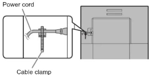
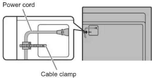
- Be sure to clamp the power cord (supplied) by using the supplied cable clamp (affixing type). When clamping the power cord, take care not to stress the terminal of the power cord. Do not bend the power cord excessively.
[PN-HW861/PN-HW751/PN-HW651]
[PN-HW551/PN-HW501/PN-HW431]
Contents
IMPORTANT INFORMATION......3
DEAR SHARP CUSTOMER....4
SAFETY PRECAUTIONS......4
TIPS AND SAFETY INSTRUCTIONS....6
MOUNTING PRECAUTIONS....7
Supplied Components....8
Part Names....9
Connecting Peripheral Equipment....12
Connecting the Power Cord ....14
Binding Cables....14
Attaching the USB flash drive cover....15
Attaching the logo sticker....16
Removing the Handles (PN-HW861/PN-HW751 only)...16
Preparing the Remote Control Unit....17
Installing the batteries ....17
Remote control operation range....17
Turning Power On/Off....20
Turning on the main power....20
Turning power on/off 20
Basic Operation 22
Using Media Player....25
Playing files....25
Auto playback....26
Playing files using the SCHEDULE function .....26
Operations during play....26
Menu Items....27
Displaying the menu screen....27
Menu item details....28
Adjustments for computer screen display ....32
Controlling the Monitor with a computer (RS-232C)...33
Computer connection....33
Communication conditions....33
Communication procedure....33
RS-232C command table....34
Controlling the Monitor with a computer (LAN)....36
Command-based control....36
Troubleshooting....37
Specifications 38
Mounting Precautions
(For SHARP dealers and service engineers)....41
Supplied Components
If any component should be missing, please contact your dealer.
☐ Liquid Crystal Display Monitor: 1
□ Remote control unit: 1
□ Power cord
☐ R03 battery ("AAA" size): 2
☐ CD-ROM (Utility Disk for Windows): 1
□ Setup Manual: 1
□ Specification sheet
□ Cable clamp: 2
□ Logo sticker: 1
☐ USB flash drive cover: 1
☐ USB flash drive cover fixing screw: 1
* SHARP Corporation holds authorship rights to the Utility Disk program. Do not reproduce it without permission.
* For environmental protection!
Do not dispose of batteries in household waste. Follow the disposal instructions for your area.
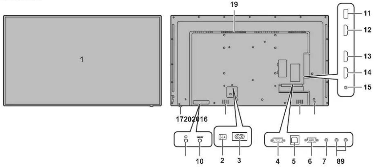
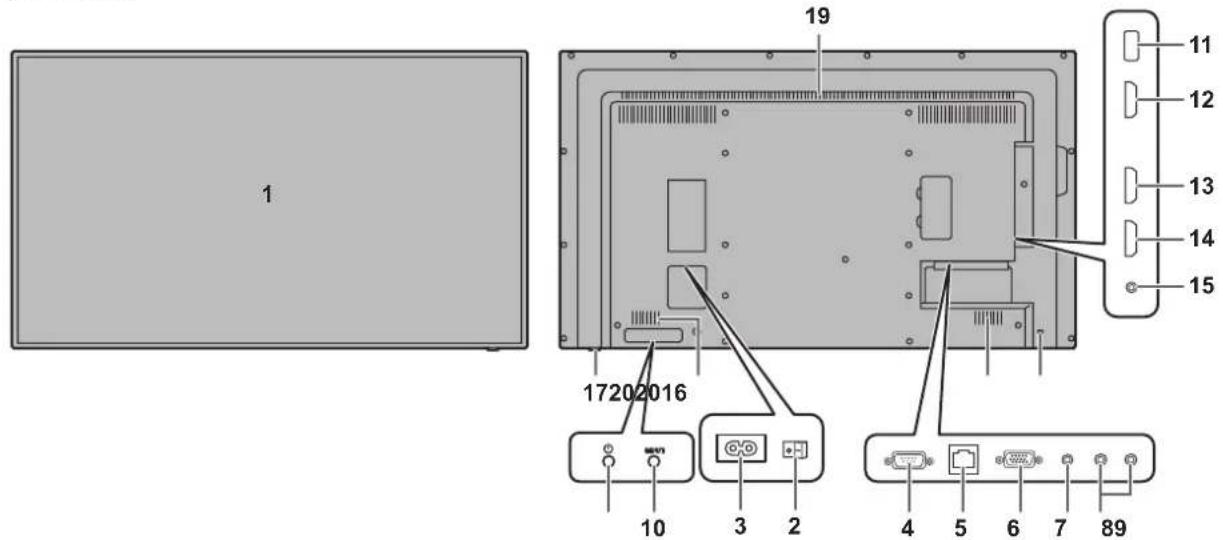
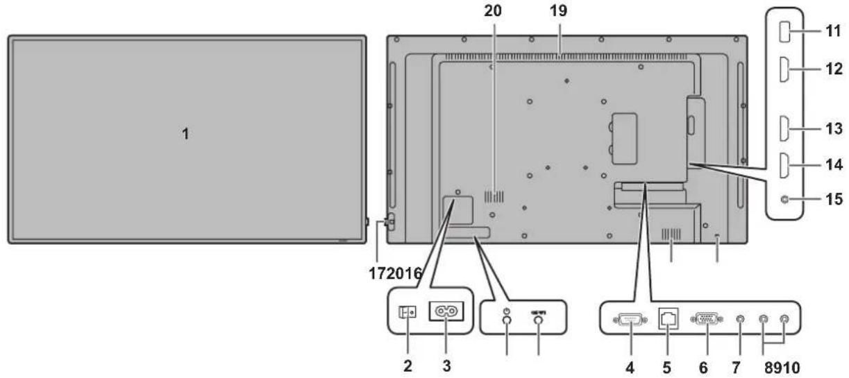
Part Names
■Front view
[PN-HW861]
■Rear view
[PN-HW751]
[PN-HW651]
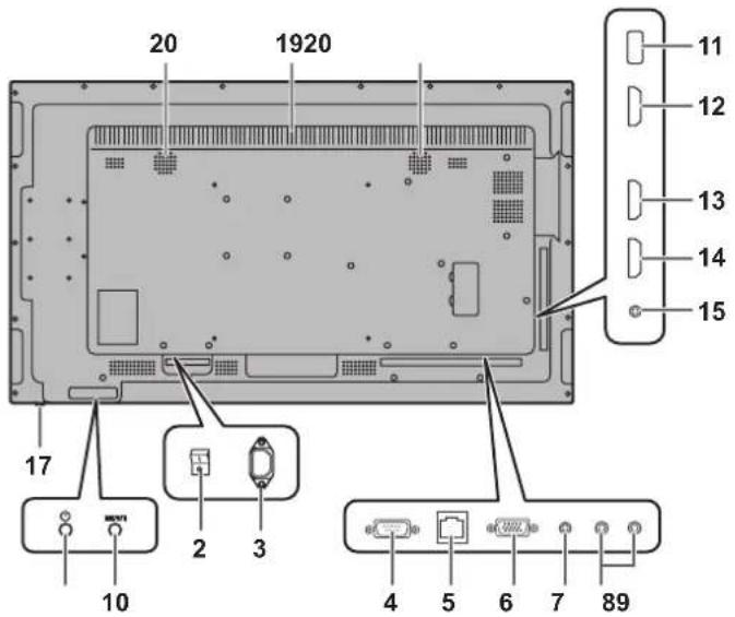
Part Names
[PN-HW551]
[PN-HW501]
[PN-HW431]
-
LCD panel
-
Main power switch (See page 14.)
-
AC input terminal (See page 14.)
-
RS-232C input terminal (See page 12.)
-
LAN terminal (See page 12.)
-
D-sub input terminal (See page 12.)
-
Audio input terminal (See page 12.)
-
Audio output terminals (See page 12.)
-
POWER button (See page 20.)
-
INPUTbutton (See page 23.)
11.USBport(See page 12.)
- HDMI1 input terminal (See page 13.)
- HDMI2 input terminal (See page 13.)
- HDMI3 input terminal (See page 13.)
- IR output terminal (See page 13.)
- Anti-theft hole 🔒)
Allows the monitor to be secured using a commercially available anti-theft lock.
- PowerLED (See page 20.) / Remote control sensor (See page 17.)
How to pull out the power LED/remote control sensor
Pull out Store
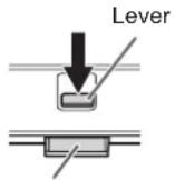
Power LED / Remote control sensor
- Slide the lever on the rear of the monitor to pull out the power LED/remote control sensor. Press the power LED/remote control sensor directly to store it inside the monitor.
- Handles (PN-HW861/PN-HW751 only) (See page 16.)
19.Vents
20.Speakers
■Remote control unit
- Signal transmitter
- Operation buttons (See page 22.)
Connecting Peripheral Equipment
! Caution
- Be sure to turn off the main power switch and disconnect the plug from the power outlet before connecting/disconnecting cables. Also, read the manual of the equipment to be connected.
- Be careful not to confuse the input terminal with the output terminal when connecting cables. Accidentally reversing cables connected to the input and output terminals may cause malfunctions and the other problems.
- Do not use any cable that has a damaged or deformed terminal. Using such cables may cause malfunctions.
TIPS
- Images may not be displayed properly depending on the computer (video card) to be connected.
- Use the automatic screen adjustment when a computer screen is displayed for the first time using D-SUB or when the setting of the computer is changed.
- If the audio output from the playback device is connected directly to speakers or other devices, the video on the monitor may appear delayed from the audio portion. Audio should be played through this monitor by connecting the playback device to the monitor's audio input, and connecting the monitor's audio output to the speakers or other devices.
- The audio input terminals used in each input mode are as follows.
| Input mode Audio input terminal | |
| HDMI1 HDMI1 input terminal | |
| HDMI2 HDMI2 input terminal | |
| HDMI3 HDMI3 input terminal | |
| D-SUB Audio input terminal | |
| USB USB port | |
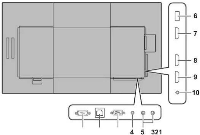
1. RS-232C input terminal
- You can control the monitor from a computer by connecting a commercially available RS-232 straight cable between this terminal and the computer.
2. LAN terminal
- You can control the monitor from a computer on a network by connecting a commercially available LAN cable between this terminal and a network.
3. D-sub input terminal
4. Audio input terminal
- Use an audio cable without resistance.
5. Audio output terminals
• The output sound varies depending on the input mode.
- The volume of the output sound can be fixed by setting AUDIO OUTPUT on the AUDIO menu.
- It is not possible to control the sound output from the audio output terminals with the AUDIO menu.
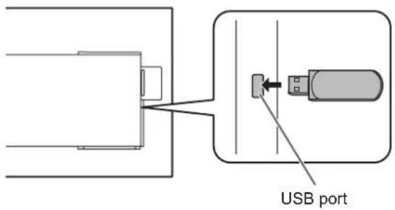
6. USB port
- Connect a USB flash drive to the USB port.
- Do not connect a USB device other than a USB flash drive.
- Turn off the power of the monitor when removing a USB flash drive.
Supported USB flash drives
| File System FAT16/32 | |
| Capacity | Up to 32 GB(maximum file size 4 GB) |
- If the USB flash drive cover will be attached, use a USB flash drive with dimensions no greater than 1-15/16 inch (50 mm) (L) × 13/16 inch (20 mm) (W) × 1/2 inch (12 mm) (H).
- Do not use a USB flash drive with a security function or a write protection function.
-
Use a USB flash drive with a shape that can be inserted in the USB port. Some USB flash drives with special shapes cannot be inserted. Do not forcibly insert a USB flash drive. This may damage the connector and cause failure.
-
HDMI1 input terminal
- HDMI2 input terminal
- HDMI3 input terminal
- Use a commercially available HDMI cable (conforming to the HDMI standard) that supports 4K.
- When HDMI is selected, it is not necessary to connect an audio cable to the audio input terminal.
- IR output terminal
- You can operate connected external connection equipment through this monitor. Point the remote control of the external connection equipment toward the remote control sensor on this monitor.
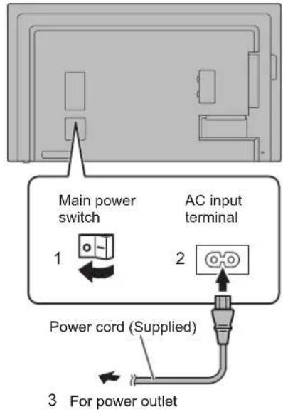
Connecting the Power Cord
! Caution
- Use only the power cord supplied with the monitor.
- Turn off the main power switch.
- Plug the power cord (supplied) into the AC input terminal.
- Plug the power cord (supplied) into the power outlet.
[PN-HW861/PN-HW751/PN-HW651]
[PN-HW551/PN-HW431]
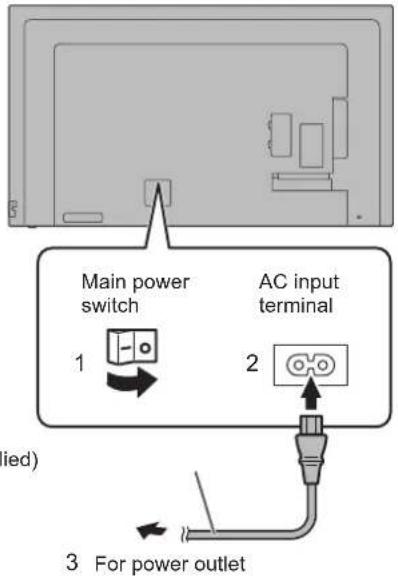
[PN-HW501]
Binding Cables
The supplied cable clamps (affixing type) can be used to clamp the power cord and cables connected to the back of the monitor.
!Caution
- Attach the supplied cable clamps to a flat surface. Do not attach over a vent.
- Remove any dust or dirt before attaching.
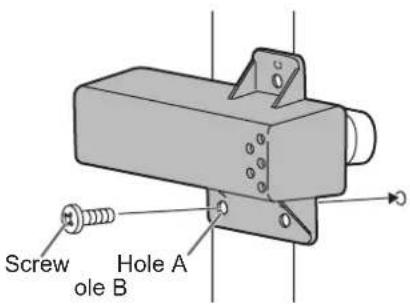
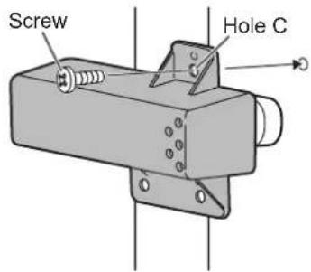
Attaching the USB flash drive cover
1. Insert the USB flash drive into the USB port.
2. Attach the USB flash drive cover and secure with the provided screw (x1).
[PN-HW861/PN-HW751/
PN-HW551/PN-HW501]: Hole B
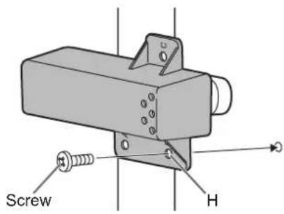
[PN-HW651]: Hole A [PN-HW431]: Hole C
TIPS
- If the USB flash drive cover will be attached, use a USB flash drive with dimensions no greater than 1-15/16 inch (50 mm) (L) × 13/16 inch (20 mm) (W) × 1/2 inch (12 mm) (H).
- When a USB flash drive cover is attached, the depth of the monitor increase. (PN-HW651/PN-HW551/PN-HW501/PN-HW431)
Attaching the logo sticker
You can attach the supplied logo sticker on this monitor.
Refer to the following example to attach the sticker as necessary.
Example for portrait orientationExample fo
Removing the Handles (PN-HW861/PN-HW751 only)
The handles can be removed.
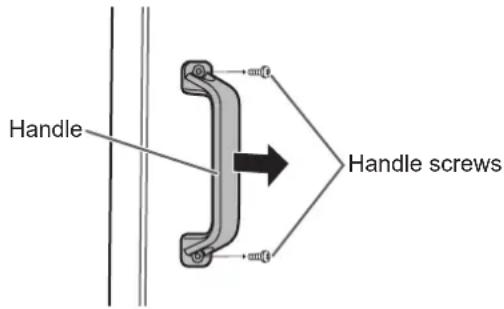
! Caution
- The removable handles and handle screws are for use with this monitor. Do not use them for any other devices.
- To attach handles, be sure to use the handles and handle screws which were removed from this monitor.
- Be sure the handles are attached securely.
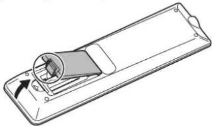
Preparing the Remote Control Unit
Installing the batteries
- Place your finger on the part marked with the ▲, and then pull the cover off.
natural_image
Line drawing of a remote control device with a scroll wheel and directional arrow (no text or symbols)- See the instructions in the compartment and put in the supplied batteries (R03 ("AAA" size) x 2) with their plus (+) and minus (-) sides oriented correctly.
- Close the cover.
TIPS
- When the batteries become exhausted, replace them with new (commercially available) batteries.
- The supplied batteries may become exhausted quickly depending on how they are stored.
- If you will not be using the remote control for a long time, remove the batteries.
• Use manganese or alkaline batteries only.
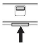
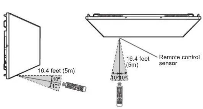
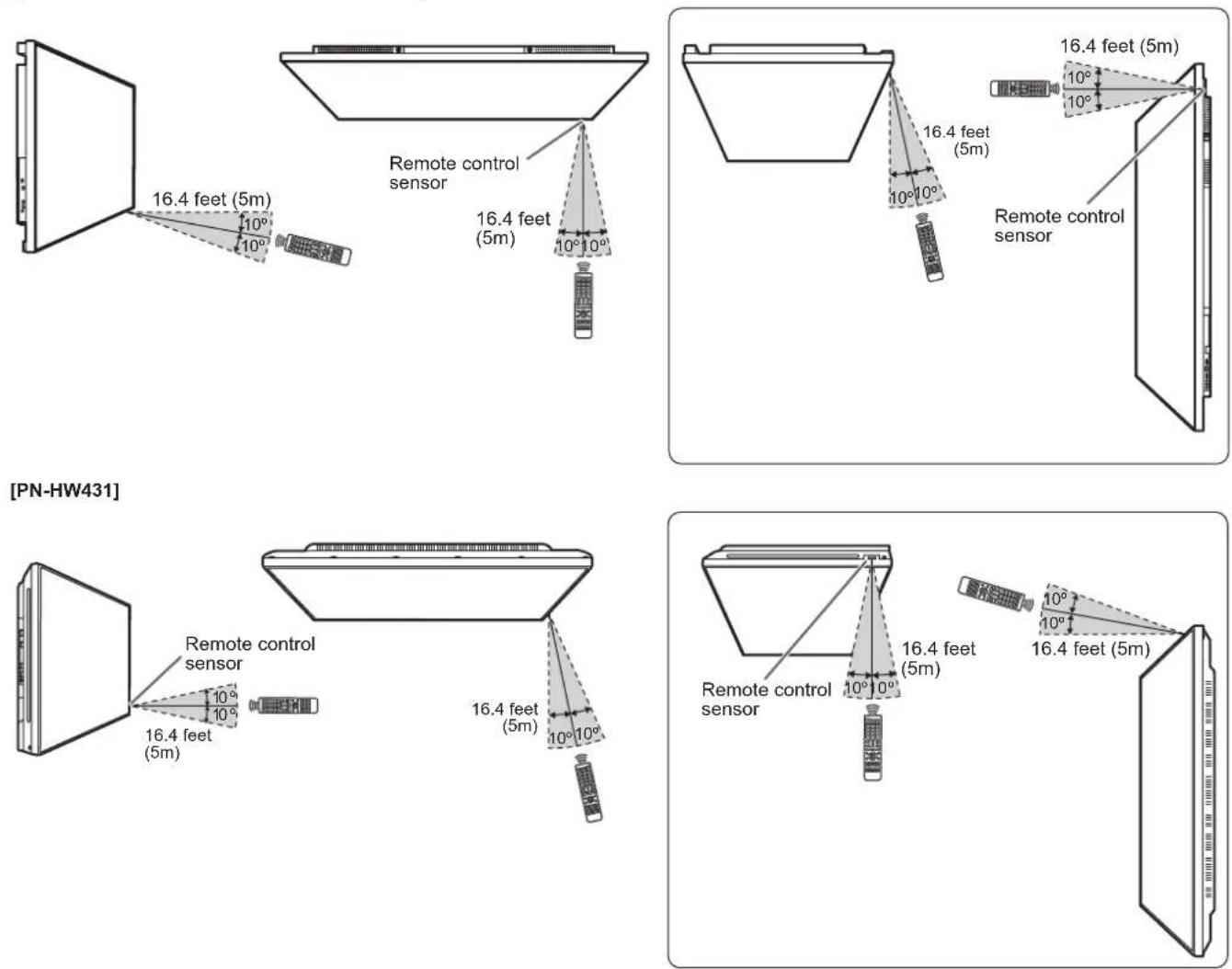
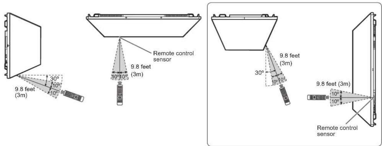
Remote control operation range
Remote control sensor out
Point the remote control unit toward the remote control sensor.
For the monitor in landscape orientation For the monitor in portrait orientation [PN-HW861]
Preparing the Remote Control Unit
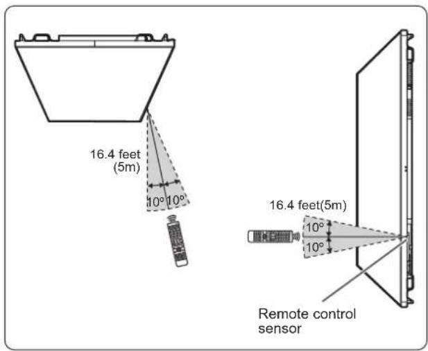
[PN-HW751/PN-HW651/PN-HW551/PN-HW501]
Remote control sensor in
The remote control can be operated even when the remote control sensor is stored inside the monitor.
Point the remote control unit toward the remote control sensor.
For the monitor in landscape orientation For the monitor in portrait orientation [PN-HW861]
[PN-HW751/PN-HW651/PN-HW551/PN-HW501]
TIPS
- Do not expose the remote control unit to shock by dropping or stepping on it. This could lead to a malfunction.
- Do not expose the remote control unit to liquids, and do not place it in an area with high humidity.
- The remote control unit may not work properly if the remote control sensor is under direct sunlight or strong lighting.
- Objects between the remote control unit and the remote control sensor may prevent proper operation.
- Replace the batteries when they run low as this may shorten the remote control's operation range.
• If a fluorescent light is illuminated near the remote control unit, it may interfere with proper operation. - Do not use it with the remote control of other equipment such as air conditioner, stereo components, etc.
Turning Power On/Off
! Caution
- Turn on the monitor first before turning on the computer or playback device.
- When switching the main power switch or the POWER button off and back on, always wait for at least 5 seconds. A short interval may result in a malfunction.
Turning on the main power
[PN-HW861/PN-HW751/PN-HW651]
[PN-HW551/PN-HW431]
[PN-HW501]
! Caution
- The main power must be turned on/off with the main power switch. Do not connect/disconnect the power cord or turn the breaker on/off while the main power switch is on.
- For a complete electrical disconnection, pull out the main plug.
Turning power on/off
Press the POWER button to turn the power ON/OFF. You can also turn the power ON/OFF by pressing the MONITOR ON button/MONITOR OFF button on the remote control unit.
![[PN-HW861] MVI](/content/2026/05/828215/images/b85d58c50ff8be89a6b3015504bd6ed20f85746f76771691fa7f9512ad67141b.jpg)
POWER buttonPower LED
[PN-HW751/PN-HW651/PN-HW551/PN-HW501]
[PN-HW431]
| Status Status of the monitor | |
| Green lit Power on | |
| Orange lit Power off (Standby mode) | |
| Green flashing Input signal waiting mode | |
TIPS
- When the main power switch is off, the monitor cannot be turned on.
- If the monitor is in the input signal waiting mode and you press the POWER button or MONITOR OFF button, the monitor enters standby mode.
- Setting the SCHEDULE flashes the power LED alternately in red and orange in standby mode.
■Operation mode
When the monitor is turned on for the first time after being shipped from the factory, the operation mode setting screen will be displayed. Set it to MODE1 or MODE2.
MODE1....OFF IF NO OPERATION is set to ON, and POWER
SAVE MODE is set to ON. (These settings can not be changed.)
If there is no operation for 4 hours or more, the monitor automatically enters standby mode. Power consumption in standby mode is also minimized.
MODE2....Will perform standard operation.
OFF IF NO OPERATION is set to OFF, and POWER SAVE MODE is set to OFF. These settings can be changed.
Even after being set, changes can be made using
OPERATION MODE, located in the menu of the monitor. (See page 30.)
■Date/time setting
- If the time has yet to be set when the monitor is first turned on, the date/time setting screen appears. Set the date and time.
- Be sure to set the date and time.
TIPS
- Set the time on a 24-hour basis.
Basic Operation
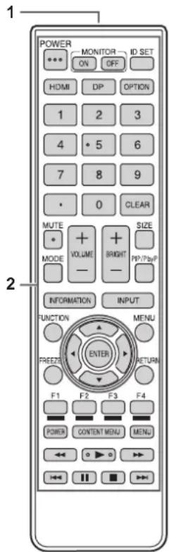
1. HDMI
Switch the input mode to HDMI1, HDMI2 or HDMI3.
2. Numeric input buttons
These buttons are used for setting such as LAN setting.
3. MUTE
Turns off the volume temporarily.
Press the MUTE button again to turn the sound back to the previous level.
4. MODE (Color mode selection)
Each time you press this button, the color mode changes in the following order:
STD (Standard) → VIVID → sRGB → HIGH ILLUMINANCE → STD...
- HIGH ILLUMINANCE is a display with colors suited to bright locations.
- sRGB is international standard of color representation specified by IEC (International Electrotechnical Commission). Color conversion is made in taking account of liquid crystal's characteristics and represents color tone close to its original image.
5. VOLUME +/- (Volume adjustment)
Press + or - to adjust the volume.
6. INFORMATION
Displays monitor information.
7. FUNCTION
Disable the MONITOR BUTTONS LOCK and REMOTE CONTROL LOCK. (See page 30.)
8. ENTER
Confirms the setting.
9. FREEZE
This is not used with this monitor.
10. Buttons for MEDIA PLAYER or operating the HDMI-connected device
- This is used in MEDIA PLAYER. For details, see page 25.
- When HDMI CEC LINK is set to AUTO, use these buttons to operate the device connected through the HDMI interface.
11. ID SET
This is not used with this monitor.
12. OPTION
This is not used with this monitor.
This is not used with this monitor.
14. SIZE (Screen size selection)
Each time you press this button, the screen size changes. (See page 24.)
15. PIP/PbyP
This is not used with this monitor.
16. BRIGHT +/- (Brightness adjustment)
Press + or - to adjust the brightness.
17. INPUT (Input mode selection)
The menu is displayed. Press the ▲ or ▼ button to select the input mode, and press the ENTER button to enter.
* You can change the input mode by pressing the INPUT button of the monitor.
| Input mode | Video Audio | |
| HDMI1 | HDMI1 input terminal HDMI1 input | terminal |
| HDMI2 | HDMI2 input terminal HDMI2 input | terminal |
| HDMI3 | HDMI3 input terminal HDMI3 input | terminal |
| D-SUB | D-sub input terminal Audio input ter | minal |
| USB USB port | USB port |
18. MENU
Displays and turns off the menu screen. (See page 27.)
19. Cursor
These buttons are used to perform operations such as selecting items, changing adjustment values, and moving the cursor.
20. RETURN
Returns to the previous screen.
■Switching the screen size
Even when the screen size is changed, the display may remain the same depending on the input signal.
| WIDE |  | Displays image so it fills the entire screen. |
| ZOOM |  | The image is enlarged to fill the entire screen without changing the aspect ratio.The edges of the image may be cut off. |
| NORMAL |  | Displays the image so it fills the screen without changing the aspect ratio. |
| Dot by Dot |  | Displays the dots of the input signals as the corresponding dots on the screen. |
TIPS
- Using this monitor's screen-size switching function to compress or expand the screen for commercial or public viewing in establishments like cafes or hotels may infringe on the rights of the creators, as protected by Copyright Law, so please be careful.
- The appearance of the original video may change if you select a screen size with a different aspect ratio than the original image (e.g. TV broadcast or video input from external equipment).
- When 4:3 video is viewed with the whole screen using the screen-size switching function of this monitor, the edge of the video may be lost or appear distorted. If you wish to respect the creator's intentions, set the screen size to "NORMAL".
- When playing commercial software, parts of the image (like subtitles) may be cropped. In this case select the optimal screen size using the screen-size switching function of this monitor. With some software, there may be noise or distortion at the edges of the screen. This is due to the characteristics of the software, and is not a malfunction.
- Depending on the original video size, black bands may remain at the edges of the screen.
Using Media Player
You can play photo, music, and video files in a USB flash drive connected to the monitor. There are the way to play the specified files/folders and the way to play as auto playback. You can also play Music file during Photo file display. For information on USB flash drive, see page 12.
■ Supported formats
The types of files that can be played are as follows. The operation of formats not indicated in the table is not guaranteed.
Photo files
| Extension Max. | resolution |
| *.jpg (*.jpeg) 15360 x 8640 | |
- Progressive JPEG files are not supported.
Music files
| Extension Audio | codec |
| *.mp3 MPEG-1 L2/L3, MPEG-2 L3 | |
Video files
Video files up to Full HD can be played.
| Extension | Video codec Audio | codec |
| *.ts MPEG2/H | .264 AAC, AC-3, MP3, LPCM | |
| *.mp4 | H.264 MP/HP@L4 | AAC, AC-3, MP3 |
-
Both video codec and audio codec need to be supported.
• Video files up to 1080p 30 Hz can be played. -
In some cases it may not be possible to play the above files.
- A maximum of 32 alphanumeric characters can be used for folder name and file name.
- Do not use a file that is over 4 GB.
Playing files
TIPS
- Files are displayed/played according to the order you copy them to a USB flash drive. Copy files to a USB flash drive according to the order you want to play.
- You can have photo or video files play automatically when a USB flash drive is connected or the power is turned on. (See page 26.)
■ Select the type of file to be played
- Insert the USB flash drive into the monitor. (See page 12.)
- Change an input mode to [USB]. (See page 23.)
- Select the type of file to be played with the ◀ or ▶ button, and press the ENTER button.
■ Playing files
-
Displays the file to be played.
Select the folder with the ◀, ▶ or button and press the ENTER button to show the files in the folder. -
Select the file you want to play, and press the ENTER button.
The file is selected.
Multiple files can be selected. You can also select files in different folders.
- Press the ▶ (Play) button.
The selected files are played.
TIPS
- The played screen size is NORMAL.
- If you press the ▶(Play) button without selecting a file, all the files in the folder will be played.
- Select "Return" folder to return to the root folder, select "Up Folder" folder to return to the next higher folder.
- The volume can be adjusted with the VOLUME button and MUTE button on the remote control.
- For operations during play, see page 26.
■ To stop play
- Press the ■(Stop) button.
Auto playback
Photos or video in a USB flash drive can be played automatically.
■ Preparations
Prepare the files. Name the file to be played "001-030" such as "001.jpg" - "030.jpg".
- Create a folder named "autoplay" in the root folder of a USB flash drive and copy the files to be automatically played to the folder.
Select the type of file.
- Change an input mode to other than [USB]. (See page 23.)
- Press the MENU button, and select SETUP with the ◀ or ▶ button, select AUTO PLAY with the ▲ or ▽ button.
- Select the type of file with the ◀br ▶button .
■ Auto playback of files
Connect a USB flash drive (see page 12) and turn on the monitor power.
Auto play starts.
You can connect a USB flash drive (see page 12) after turning on the monitor power.
Auto play starts.
TIPS
- Photos and video cannot be played automatically at the same time.
- Auto play repeatedly plays all photo or video files in the "autoplay" folder.
■ To stop auto play
- Press the ■(Stop) button.
Playing files using the SCHEDULE function
The image files (in .jpg (.jpeg)) or video files (in .mp4 format) in a USB flash drive can be automatically played using the SCHEDULE function. (See page 31.)
Operations during play
When playback starts, you can display the operation bar in the bottom of the screen by pressing the MENU [square] button.
You can perform the actions below while the operation bar is displayed.
| Play / Pause Play the current file./Pause the playing file. | |
| FB Fast backward playing the file.(Music and Movie only) | |
| FF Fast forward playing the file.(Music and Movie only) | |
| Prev. Go to the previous file. | |
| Next Go to the next file. | |
| Stop Stop the playing file. | |
| Repeat None / Repeat 1file / Repeat ALL | Repeat none:Play files in the playlist only once.Repeat 1:Play and repeat the current file.Repeat all:Play and Repeat files in the playlist. |
| Set A / Set B / None | Play and repeat set interval.SetA:Set the interval of the start point.SetB:Set the interval of the end point.(Music and Movie only) |
| Random On / Random Off | Random On:Play and repeat files of the playlist in random.Random Off:Play files of the playlist in order. |
| Music On / Music Off | Setting to “Music On”, the photo and music files in the same folder are played at the same time.(Photo only) |
| Playlist Show Playlist. | |
| Info | Show Playing file information. |
| Rotate (Clockwise) | Rotate the current file 90 degrees clockwise temporarily.(Photo only) |
| Rotate (Anti-Clockwise) | Rotate the current file 90 degrees Anti-clockwise temporarily.(Photo only) |
| Zoom In | The file zooms in.(Photo only) |
| Zoom Out | The file zooms out.(Photo only) |
| Move View | Select view area in zoomed.(Photo only) |
| Slideshow Time | Select Slideshow time.(Photo only) |
Menu Items
Displaying the menu screen
Video and audio adjustment and settings of various functions are enabled. This section describes how to use the menu items. See page 28 for details of each menu items.
! Caution
- Do not turn the main power switch off while the menu items are being displayed. Doing so may initialize the settings.
- This cannot be displayed when the input mode is [USB]. Change an input mode to other than [USB] before performing these operations.
■Example of operation
(Adjusting CONTRAST in the PICTURE menu)
- Press the MENU button to display the menu screen.
- Press the ◀or button to select PICTURE.
- Press the ▲ or ▼ button to select CONTRAST.
- Press the or button to adjust the setting, and press the RETURN button.
- Press the MENU button to close the menu screen.
TIPS
- The menu will differ depending on the input mode.
■Menu screen display
1 Name of the menu
2 An item being selected (highlighted)
TIPS
- Items that cannot be selected appear in gray. (e.g. Function not supported by the current input signal)
Menu item details
The menu will differ depending on the input mode.
PICTURE
COLOR MODE
Changes the color mode on the screen. The color mode on the screen can also be changed using a remote control unit. (See page 22 for details.)
ADVANCED
SIZE
This is the same setting as when SIZE button is pressed. See page 22 for an explanation of the setting.
WHITE BALANCE
THRU ......Displays the input signal level as is.
PRESET......Selects the color temperature using PRESET.
USER...... Adjusts R-/G-/B-CONTRAST respectively using USER.
PRESET
Selects the color temperature when the WHITE BALANCE is set to PRESET.
The setting values are shown for reference. The color temperature of the screen varies over time. This function is not intended to keep the color temperature constant.
USER
Adjusts each item when the WHITE BALANCE is set to USER.
R-CONTRAST....Adjusts bright-toned red component.
G-CONTRAST ... Adjusts bright-toned green component.
B-CONTRAST....Adjusts bright-toned blue component.
NR
Reduce the image noise
Setting a higher level reduces more noise. However, it may cause blurring on an image.
ACTIVE CONTRAST
Set whether to ON or OFF active contrast.
GAMMA
Selects the gamma.
HDMI RGB INPUT RANGE
Sets the RGB input signal range.
When using HDMI set to AUTO, the RGB input signal range is detected automatically. Use AUTO normally.
If the RGB input signal range cannot be set appropriately even when using AUTO, set according to the image. When the setting is different, images will be displayed with washed out blacks and compressed gradients.
BRIGHT
Adjusts the backlight brightness.
BLACK LEVEL
Adjusts the entire brightness of the video signals.
CONTRAST
Adjusts the difference between the bright and dark portions of the image.
COLORS
Adjusts the color intensity.
TINT
Adjusts the hue. Selecting + changes the color towards green, and selecting - changes it towards magenta.
SHARPNESS
Adjusts the sharpness of the image.
AUDIO
| TREBLE |
| Adjusts the volume of treble-level sound. |
| BASS |
| Adjusts the volume of bass-level sound. |
| BALANCE |
| Adjusts the balance of the audio sound between right and left. |
| SPEAKER |
| Selects the speaker to be used. |
| AUDIO OUTPUT |
| Sets the volume of sound output from the audio output terminals.VARIABLE ......You can adjust the volume using VOLUME.FIXED ......Fixes the sounds. |
SETUP
| LANGUAGE |
| Sets the display language for the menu screen. |
| DATE/TIME SETTING |
| Set the date and time.TIME FORMAT ...... Sets the time display format.Select 12- or 24-hour time. |
| SCHEDULE (See page 31.) |
| You can turn the power on/off at a specified time.Files in a USB flash drive can also be played at a specified time. |
| HDMI CEC LINK |
| AUTO......Use the HDMI CEC function.If the device connected to the HDMI input terminal supports CEC, the input mode of the monitor changes to HDMI when playback starts on the device.OFF ......HDMI CEC function is not used. |
| HDMI MODES |
| HDMI MODES settings change how the content displayed is processed and decoded.MODE1 is default and will support most common color spaces and other encoding signals.MODE2 should be used for YCbCr 4:2:0 at 4K Vsync 50/60 Hz signals or when non 4K devices are connected and content onscreen are not what is expected. |
| COMMUNICATION SETTING |
| RS-232C/LAN SELECTSelects the method with which to control the monitor from the computer. |
| LAN SETUPConfigures the settings to control the monitor from the computer via LAN. (See page 36.) |
Menu Items
SCREEN
AUTO (D-SUB)
The CLOCK, PHASE, H-POS, and V-POS are automatically adjusted.
Pressing the ENTER button performs adjustment. Use this automatic adjustment when you use the D-SUB to display a computer screen for the first time or when you change the setting of the computer. (See page 32.)
CLOCK (D-SUB)
Adjusts frequency for sampling clock for applicable video.
Adjust when there is flickering in the form of vertical stripes.
When using the adjustment pattern (see page 32), make adjustments so that no vertical stripe noise appears in it.
PHASE (D-SUB)
Adjusts sampling clock phase for applicable video. Useful when small characters appear with low contrast and/or there are flickers at corners. When using the adjustment pattern (see page 32), make adjustments so that no horizontal stripe noise appears in it.
* Adjustments to PHASE should be made only after CLOCK has been correctly set.
H-POS (D-SUB)
Adjust the horizontal position of the image.
V-POS (D-SUB)
Adjust the vertical position of the image.
RESET
Resets the values of the SCREEN menu items to the factory default settings.
Select YES and then press the ENTER button.
OPERATION MODE
MODE1.....OFF IF NO OPERATION is set to ON, and POWER SAVE MODE is set to ON.
(These settings can not be changed.)
MODE2.....Will perform standard operation. OFF IF NO OPERATION is set to OFF, and POWER SAVE MODE is set to OFF.
These settings can be changed.
POWER SAVE MODE
When OFF is selected, startup time from standby mode is reduced. Note, however, that more power will be consumed in standby mode.
When ON is selected, current consumption is reduced while the monitor is in standby mode. Note, however, that the startup time from standby mode becomes longer.
If set to ON, certain RS-232C commands and LAN control cannot be used in standby mode. (See pages 33 and 36.)
OFF IF NO OPERATION
Set whether or not the monitor goes into standby mode when there is no operation from the remote control or RS-232C / LAN.
After setting this to ON, the monitor goes into standby mode when there is no operation for more than 4 hours.
POWER MANAGEMENT
POWER MANAGEMENT determines whether or not to switch modes from no signal to the input signal waiting mode.
NO SIGNAL AUTO INPUT SEL.
Specify whether to change inputs automatically. When ON is selected and no signal is present in the selected input mode, the monitor automatically changes the selected mode to another mode where a video signal is present.
When video signals exist in multiple input modes, the switching priority is as follows:
USB (when a USB flash drive is connected), HDMI1, HDMI2, HDMI3, D-SUB
(Input mode switching may take 15 seconds or more, depending on the connected equipment. When there are no signals at any of the input terminals, switching is continued until an input signal is detected and the monitor does not enter input signal waiting mode.)
AUTO PLAY
Set the type of file to be automatically played from a USB flash drive. (See page 26.)
MONITOR BUTTONS LOCK
You can disable the monitor buttons.
To disable MONITOR BUTTONS LOCK, press the FUNCTION button and then press the ▲, ▼ and buttons in this sequence.
REMOTE CONTROL LOCK
You can disable the remote control buttons.
To disable REMOTE CONTROL LOCK, press the FUNCTION button and then press the ▲, ▼ and buttons in this sequence. You can also disable REMOTE CONTROL LOCK by turning off the main power, and then turning on the main power while pressing the POWER button on the monitor. Use this method to disable when auto play has been set in Media Player.
THERMAL SENSOR SETTING
Select the installation direction of the monitor.
LANDSCAPE......Landscape orientation
PORTRAIT ...... Portrait orientation
LED
Specifies whether to light the power LED.
INFORMATION
Displays monitor information.
ALL RESET
Resets the settings to the factory default settings.
TIPS
- When WHITE BALANCE is set to THRU, BLACK LEVEL, CONTRAST, TINT, COLORS, GAMMA, PRESET and USER cannot be set.
- If COLOR MODE is set to sRGB, the following items cannot be set.
WHITE BALANCE, PRESET, USER, ACTIVE CONTRAST, and GAMMA - When the COLOR MODE is set to VIVID or HIGH ILLUMINANCE, GAMMA cannot be adjusted.
■SCHEDULE
You can set the time to switch the monitor on and off.
An auto play file in a USB flash drive (see page 26) can also be played at a specified time. Set INPUT in SCHEDULE to [USB].
Set this function with SCHEDULE in the SETUP menu. (See page 29.)
- Insert the USB flash drive to be played into USB port on the monitor when playing files. (See page 12.)
- Press the ▲ or ▼ button to select the SCHEDULE number, and press the ENTER button.
- Set the SCHEDULE. (See below)
Move through the items with the ▲ or ▼button, and set each item.
- Press the MENU button.
SCHEDULE becomes effective.
(1) ON/OFF
Enable/disable the SCHEDULE.
(2) ON TIME
Specify the time the power turns on.
Set the time with the ◀, ▶, △ button and press the RETURN button.
(3) OFF TIME
Specify the time the power turns off.
Set the time with the ◀, ▶, △ button and press the RETURN button.
(4) REPEAT MODES
Select the day of the week the schedule will be executed.
Press the ENTER button to change the setting, and press the RETURN button.
- ONLY ONCE The SCHEDULE will be executed once only regardless of the day of the week. When the schedule is set to ONLY ONCE, the setting is cleared after the schedule is executed.
- EVERY SUN - EVERY SAT Executes the SCHEDULE on the specified day every week. Multiple days of the week can be specified.
(5) INPUT
Specify the input mode at power on.
!Caution
- Do not turn off the main power after setting the SCHEDULE.
- Set the time for both power-on and power-off. The time for either only cannot be set. Schedule ON and then OFF only take place in standby mode and input signal waiting mode.
- Specify the correct date and time. (See page 29.) SCHEDULE does not function unless the date and time are specified.
- Check regularly that the set date and time are correct.
TIPS
- Up to 7 SCHEDULE items can be registered.
- Setting the SCHEDULE flashes the power LED alternately in red and orange in standby mode.
- A SCHEDULE that has a small number has precedence over that of a large number when schedules overlap.
- POWER SAVE MODE is set to ON, SCHEDULE is unenabled.
Adjustments for computer screen display
■Automatic adjustment
When you use the D-SUB to display a computer screen for the first time, or when you change the setting of the computer, use the automatic screen adjustment.
- Switch the input to D-SUB and display the adjustment pattern. (See the description below.)
- Press the MENU button and use the ◀ or ▶ button to display the SETUP menu.
- Press the ▲ or ▼ button to select SCREEN, and press the ▶ button.
- Press the ▲ or ▼ button to select AUTO, and press the ▶ button.
The automatic adjustment is complete in several seconds.
- Press the MENU button to close the menu screen.
TIPS
- If the screen cannot be adjusted properly with one automatic adjustment, repeat the automatic adjustment two or three times. Try manual adjustment if necessary.
■Screen display for adjustment
Before making adjustments in the SCREEN menu or PICTURE menu, display an image to brighten the entire screen. If you are using a Windows computer, use the adjustment pattern on the supplied CD-ROM.
Opening the adjustment pattern
The following example is performed in Windows 7.
- Load the supplied CD-ROM into the computer's CD-ROM drive.
- Open [CD Drive] in [Computer].
- Double-click [Adj_uty.exe].
The adjustment pattern will appear.
Adjust the screen automatically or manually.
natural_image
Pure electrical circuit lines without any symbols- When adjustment is finished, press the [Esc] on the computer's keyboard to quit the adjustment program.
- Eject the CD-ROM from the CD-ROM drive.
TIPS
- If the display mode on the computer you are using is 65000 colors, the color levels in the color pattern may appear differently or grayscale may appear to be colored. (This is due to the specifications of the input signal and is not a malfunction.)
Controlling the Monitor with a computer (RS-232C)
You can control this monitor from a computer via RS-232C (COM port) on the computer.
TIPS
- To control the monitor via RS-232C, set RS-232C/LAN SELECT to RS-232C.
- You cannot use RS-232C and LAN control simultaneously.
Computer connection
Connect with RS-232 straight cable between the computer's COM port (RS-232C connector) and the RS-232C input terminal on the monitor.
flowchart
graph LR
    A["RS-232C input terminal"] --> B["RS-232 straight cable (commercially available)"]
    B --> C["To COM port"]
    C --> D["Computer"]
Communication conditions
Set the RS-232C communication settings on the computer to match the monitor's communication settings as follows:
| Baud rate 9600bps | Stop bit | 1 bit |
| Data length 8 bits Flow control | None | |
| Parity bit None |
Communication procedure
■Command format
When a command is sent from the computer to the monitor, the monitor operates according to the received command and sends a response message to the computer.
Example: VOLM0030 VOLM 30
* Be sure to input 4 characters for the parameter. Pad with spaces (“_”) if necessary.
("☐" is a return code (0D_H, 0A_H or 0D_H))
Wrong : VOLM30
Right : VOLM 30
The current value can be returned by using “?” as the parameter.
Example:
VOLM ? ? ? ? ←
From computer to monitor (How much is current volume setting?).
30
From monitor to computer (Current volume setting: 30).
■Response code format
When a command has been executed correctly
A response is returned after a command is executed.
When a command has not been executed
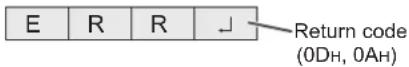
TIPS
- "ERR" is returned when there is no relevant command or when the command cannot be used in the current state of the monitor.
- If communication has not been established for reasons such as a bad connection between the computer and monitor, nothing is returned (not even ERR).
- "ERR" may be returned when a command cannot be received correctly due to interference from the surrounding environment.
Please ensure that the system or software resends the command if this occurs.
■Communication interval
- After OK or ERR is returned, you must send the following commands.
To set a timeout for the command response, specify 10 seconds or longer. - Provide an interval of 100 ms or more between the command response and the transmission of the next command.
RS-232C command table
How to read the command table
Command: Command field (See page 33.)
Direction: W When the "Parameter" is set in the parameter field (see page 33), the command functions as described under "Control/Response Contents".
R The returned value indicated under "Reply" can be obtained by setting "????", "(repeater control) in the parameter field. (See page 33.)

Parameter: Parameter field (See page 33.)
Reply: Response (Returned value)
* : When POWER SAVE MODE is set to OFF:
“●/○”: Indicates a command which can be used in standby mode or when the power is on.
“-” : Indicates a command which can be used when the power is on. Cannot be used in standby mode.
When POWER SAVE MODE is set to ON:
“●”:Indicates a command which can be used in standby mode or when the power is on.
“○/—”: Indicates a command which can be used when the power is on. Cannot be used in standby mode.
Power control/Input mode selection
| Function | Command | Direction | Parameter | Reply | Control/Response contents | * | |
| POWER CONTROL | POWR | W | 0 | Switches to standby mode. | ● | ||
| 1 | Returns from standby mode. | ||||||
| R | 0 Standby mode | ||||||
| 1 Normal mode | |||||||
| 2 Input signal waiting mode | |||||||
| INPUT MODE SELECTION | INPS | W | 0 | Toggle change for input mode. | - | ||
| 2 | D-SUB | ||||||
| 10 | HDMI1 | ||||||
| 11 | USB | ||||||
| 13 | HDMI2 | ||||||
| 18 | HDMI3 | ||||||
PICTURE menu
| Function | Command | Direction | Parameter | Reply | Control/Response contents | * |
| BRIGHT | VLMP | WR | 0-50 | 0-50 | - | |
| SIZE (Screen size selection) | WIDE | WR | 1-4 | 1-4 | 1: WIDE, 2: NORMAL, 3: Dot by Dot, 4: ZOOM | |
| COLOR MODE | BMOD | WR | 0 | 0 | STD | |
| 2 | 2 | VIVID | ||||
| 3 | 3 | sRGB | ||||
| 4 | 4 | HIGH ILLUMINANCE | ||||
| WHITE BALANCE | WHBL | WR | 0-2 | 0-2 | 0:THRU, 1:PRESET, 2:USER | |
| R-CONTRAST | CRTR | WR | 0-255 | 0-255 | "ERR" when WHBL is not set to 2. | |
| G-CONTRAST | CRTG | WR | 0-255 | 0-255 | ||
| B-CONTRAST | CRTB | WR | 0-255 | 0-255 |
SETUP menu
| Function | Command | Direction | Parameter | Reply | Control/Response contents | * |
| Telnet User name | USER | WR | XXXXXXXXX | XXXXXXXXX | 8 characters or less; half-width alphanumeric characters, “-”, and “_”. (The field can be left blank, but spaces cannot be entered.) | - |
| Telnet Password | PASS | WR | XXXXXXXXX | XXXXXXXXX | 8 characters or less; half-width alphanumeric characters, “-”, and “_”. (The field can be left blank, but spaces cannot be entered.) | |
| THERMAL SENSOR SETTING | STDR | WR | 0-1 | 0-1 | 0: LANDSCAPE, 1: PORTRAIT | |
| Model | INF1 | R | Value | |||
| Serial no. | SRNO | R | Value | |||
| AUTO | ASNC | W | 1 | Adjust CLOCK/PHASE/H-POS/V-POS automatically in D-SUB | ||
| ALL RESET | RSET | W | 0 |
Others
| Function | Command Direction | Parameter Reply Control/Response contents * | ||||
| VOLUME VOLM WR 0-31 0-31 | - | |||||
| MUTE AUDIO MUTE WR 0-1 0-1 0: OFF, 1: ON | ||||||
| Temperature sensor DSTA R 0 Internal temperature normal | ● | |||||
| 1 Internal temperature abnormal has occurred and the monitor is in standby mode | ||||||
| 2 Internal temperature abnormal occurred (To delete the information of temperature abnormal, turn off the main power.) | ||||||
| 3 Internal temperature abnormal has occurred and backlight brightness is dimmed | ||||||
| 4 Temperature sensor abnormal | ||||||
| Temperature acquisition | ERRT | R | Value | Returns the temperature at the temperature sensors.Indicates a temperature sensor abnormality when "126" is returned. | - | |
Controlling the Monitor with a computer (LAN)
Your monitor can be connected to a LAN allowing you to control it from a computer on the LAN.
The connection requires a commercially available LAN cable (UTP cable, Category 5, straight through).
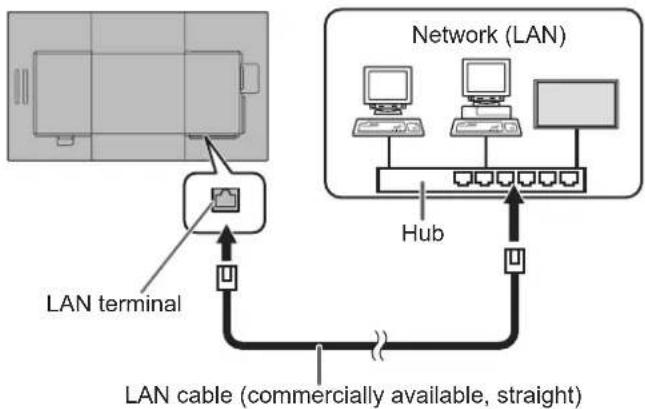
flowchart
graph TD
    A["LAN terminal"] --> B["Network (LAN)"]
    B --> C["Hub"]
    C --> D["LAN cable (commercially available, straight)"]
    style A fill:#f9f,stroke:#333
    style B fill:#ccf,stroke:#333
    style C fill:#cfc,stroke:#333
    style D fill:#fcc,stroke:#333
TIPS
- When POWER SAVE MODE is set to ON, the control is disabled in the standby mode.
- To control the monitor via LAN, set RS-232C/LAN SELECT to LAN. (See page 29.)
- You cannot use RS-232C and LAN control simultaneously.
■To set on the monitor
Set RS-232C/LAN SELECT of COMMUNICATION SETTING on the SETUP menu to LAN, and then set the LAN SETUP options. (See page 29.)
After setting each item, select SET and press the ENTER button.
VIEW NETWORK SETTINGS
Displays LAN setting information.
DHCP CLIENT
If your LAN has a DHCP server and you wish to obtain an address automatically, change this setting to ON. To set the address manually, set this to OFF.
IP ADDRESS
If the DHCP CLIENT is set to OFF, specify an IP address. Press the ◀ or ▶ button to select the items, and enter the values with the numeric input buttons (0 to 9). You can also change the values with the ▲ or ▽ button.
SUBNET MASK
If the DHCP CLIENT is set to OFF, specify the subnet mask. Press the ◀ or ▶ button to select the items, and enter the values with the numeric input buttons (0 to 9). You can also change the values with the ▲ or ▽ button.
DEFAULT GATEWAY
If the DHCP CLIENT is set to OFF, specify the default gateway. If you are not using a default gateway, specify "000.000.000.000". Press the ◀ or ▶ button to select the items, and enter the values with the numeric input buttons (0 to 9). You can also change the values with the ▲ or ▽ button.
SET
Save the setting.
Command-based control
You can control the monitor using RS-232C commands (see page 34) via terminal software and other appropriate applications.
Read the manual for the terminal software for detailed instructions.
(1) Connect the computer to the monitor.
- Specify the IP address and data port number (10008) and connect the computer to the monitor.
When connection has been established successfully, [Login:] is returned as response. - Send the user name.
- Send [user name] + [ ]
- If the user name is not set, send [☐].
-
When the transmission is successful, [ ☐Password:] is returned as response.
-
Send the password.
-
Send [password] + [ ]
- If the password is not set, send [ □].
- When the transmission is successful, [OK ☐] is returned as response.
(2) Send commands to control the monitor.
- The commands used are the same as those for RS-232C. Refer to the communication procedure (see page 33) for operation.
- Usable commands are provided in the RS-232C command table (see page 34).
(3) Disconnect the connection with the monitor and quit the function.
- Send [BYE] When the transmission is successful, [goodbye] is returned and the connection is disconnected.
Troubleshooting
If you are experiencing any problem with your display, before calling for service, please review the following troubleshooting tips.
There is no picture or sound.
- The power LED is off.
- Is power supplied to this monitor?
- Is the power cord disconnected? (See page 14.)
- Is the main power switch off? (See page 20.)
• The power LED lights orange.
- This monitor is in standby mode. Turn on the power. (See page 20.)
• The power LED flashes green.
- There is no input signal.
- Is an input mode selected that is appropriate for the input terminal to which the cable is connected? (See page 23.)
- If any external equipment is connected, make sure the equipment is operating (playing back).
Remote control does not work.
- Are the batteries inserted with polarity (+,-) aligned? (See page 17.)
• Are the batteries exhausted? - Point the remote control unit toward the monitor's remote control sensor. (See page 17.)
Sound from left and right speakers is reversed.
Sound is heard from only one side.
- Are audio cables connected properly?
There is a picture but no sound.
• Is the sound muted?
- Make sure the volume is not set to minimum.
- Are audio cables connected properly?
Unstable video.
• The signal may be incompatible.
- Try the automatic screen adjustment when D-SUB is in use.
The video from the HDMI input terminal does not appear properly.
- Does the HDMI cable support 4K, and is it HDMI standard compliant? The monitor will not work with cables that are not standard compliant.
- Is the input signal compatible with this monitor? (See pages 38 and 39.)
- If the connected device does not support 4K, set HDMI MODES to MODE2.
The video from D-Sub input terminal does not appear correctly.
- Is the input signal compatible with this monitor? (See page 38.)
Control buttons do not work.
There is no picture.
- Load noises from outside may be interfering with normal operation. Turn off the main power and turn it on after waiting at least 5 seconds, and then check the operation.
The input mode changes automatically.
- When NO SIGNAL AUTO INPUT SEL. is ON and the current video signal input stops, the input mode automatically changes to the mode of an active video signal.
Consequently, the input mode may change even in the following cases:
- When a computer enters standby mode.
- When video play is stopped with a playback device.
When "AUTO DIMMING" is displayed.
- When the internal temperature of the monitor rises excessively, the brightness of the backlight automatically decreases in order to prevent a further temperature rise. If you attempt to adjust the brightness while the monitor is in this state, "AUTO DIMMING" is displayed and you cannot change the brightness.
- Remove the cause of the excessive temperature rise.
The monitor makes a cracking sound.
- You may occasionally hear a cracking sound from the monitor. This happens when the cabinet slightly expands and contracts according to change in temperature. This does not affect the monitor's performance.
The Power LED is flashing in red and green alternately. When “TEMPERATURE” is displayed in the corner of the screen.
- When the internal temperature of the monitor rises excessively, the brightness of the backlight decreases automatically in order to prevent high-temperature-related problems. When this occurs, "TEMPERATURE" is displayed on the screen and the Power LED flashes red and green alternately.
- If the internal temperature rises further, the monitor automatically enters standby mode. (The Power LED continues flashing red and green alternately.)
- Remove the cause of the excessive temperature rise.
- If the monitor enters standby mode due to a rise in temperature, to return to normal display, turn the power switch off and then back on again. The monitor, however, will enter standby mode again if the cause of the temperature rise is not eliminated. (See page 7.)
- Check whether the monitor is placed at a location where a quick rise in temperature is likely. Internal temperature rises quickly if the vents on the monitor are blocked.
- Internal temperature rises quickly if dust accumulates inside the monitor or around the vents. Remove dust if possible. Ask SHARP dealer about removing internal dust.
Specifications
■DDC (plug and play)
The monitor supports the VESA DDC (Display Data Channel) standard.
DDC is a signal standard for plug and play between monitors and computers. Information about resolution and other parameters is exchanged between the two. This function can be used if the computer supports DDC and it has been configured to detect plug-and-play monitors.
There are several types of DDC, depending on the communication method used. This monitor supports DDC2B.
■Compatible signal timing (PC)
| Screen resolution Hsync Vsync Dot frequency | Digital | Analog (D-SUB) | ||||
| HDMI | ||||||
| VESA 640 × 480 31.5kHz 60Hz 25.175MHz Yes Yes | ||||||
| 800 × 600 37.9kHz 60Hz 40.0MHz Yes Yes | ||||||
| 848 × 480 31.0kHz 60Hz 33.75MHz - Yes | ||||||
| 1024 × 768 48.4kHz 60Hz 65.0MHz Yes Yes | ||||||
| 1280 × 800 49.7kHz 60Hz 83.5MHz Yes Yes | ||||||
| 1280 × 960 60.0kHz 60Hz 108.0MHz Yes Yes | ||||||
| 1280 × 1024 | 64.0kHz | 60Hz | 108.0MHz | Yes | Yes | |
| 80.0kHz 75Hz | 135.0MHz | Yes Yes | ||||
| 1360 × 768 47.7kHz 60Hz 85.5MHz Yes | - | |||||
| 1400 × 1050 | 65.3kHz | 60Hz | 121.75MHz | Yes | - | |
| 1440 × 900 55.9kHz 60Hz 106.5MHz Yes Yes | ||||||
| 1680 × 1050 | 65.3kHz 60Hz | 146.25MHz Yes Yes | ||||
| Wide | 3840 × 2160 | 54.0kHz | 24Hz | 297.0MHz | Yes | - |
| 56.25kHz | 25Hz | 297.0MHz | Yes | - | ||
| 67.5kHz 30Hz | 297.0MHz | Yes | - | |||
| 112.5kHz | 50Hz | 594.0MHz | Yes | - | ||
| 135kHz | 60Hz | 594.0MHz | Yes | - | ||
| 4096 × 2160^*1 | 54.0kHz 24Hz | 297.0MHz | Yes | - | ||
| 56.0kHz | 25Hz 297.0MHz Yes | *2 | - | |||
| 67.0kHz 30Hz | 297.0MHz Yes | *2 | - | |||
| 112.5kHz | 50Hz | 594.0MHz | Yes | - | ||
| 135.0kHz | 60Hz | 594.0MHz | Yes | - | ||
| 1280 × 720 44.7kHz 60Hz 74.4MHz Yes Yes | ||||||
| 1920 × 1080 | 67.5kHz | 60Hz | 148.5MHz | Yes | Yes | |
| US TEXT | 720 × 400 | 31.5kHz | 70Hz | 28.3MHz | Yes | Yes |
*1 Displays a reduced image, except in Dot by Dot. In Dot by Dot, the image will be cut down to panel size then displayed.
*2 Compatible when HDMI MODES is MODE1.
- Depending on the connected computer, images may not be displayed properly even if the compatible signal described above is input.
■Compatible signal timing (AV)
| Screen resolution Frequency HDMI | ||
| 4096 × 2160p 24Hz Yes | ||
| 25Hz Yes | ||
| 30Hz Yes | ||
| 50Hz Yes | ||
| 59.94Hz Yes | ||
| 60Hz Yes | ||
| 3840 × 2160p 24Hz Yes | ||
| 25Hz Yes | ||
| 30Hz Yes | ||
| 50Hz Yes | ||
| 59.94Hz Yes | ||
| 60Hz Yes | ||
| 1920 × 1080p 24Hz Yes | ||
| 50Hz Yes | ||
| 59.94Hz Yes | ||
| 60Hz Yes | ||
| 1920 × 1080i 50Hz Yes | ||
| 59.94Hz Yes | ||
| 60Hz Yes | ||
| 1280 × 720p 50Hz Yes | ||
| 59.94Hz Yes | ||
| 60Hz Yes | ||
| 720 × 576p 50Hz Yes | ||
| 720 × 480p 59.94Hz Yes | ||
| 60Hz Yes | ||
| 640 × 480p(VGA) 59.94Hz Yes | ||
| 60Hz Yes | ||
| 720(1440) × 576i 50Hz Yes | ||
| 720(1440) × 480i 59.94Hz Yes | ||
| 60Hz Yes | ||
Specifications
■HDMI input terminal pins
(HDMI Connector)
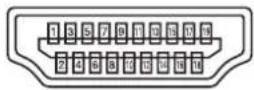
| No. | Function No. Function | ||
| 1 | TMDS data 2+ 11 TMDS clock | shield | |
| 2 | TMDS data 2 shield 12 TMDS | clock- | |
| 3 | TMDS data 2- 13 CEC | ||
| 4 | TMDS data 1+ 14 N.C. | ||
| 5 | TMDS data 1 shield 15 SCL | ||
| 6 | TMDS data 1- 16 SDA | ||
| 7 | TMDS data 0+ 17 DDC/CEC | GND | |
| 8 | TMDS data 0 shield 18 +5V | ||
| 9 | TMDS data 0- 19 Hot-plug detection | ||
| 10 | TMDS clock+ | ||
■RS-232C input terminal pins
(D-sub 9 pin)
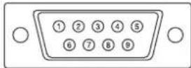
| No. | Function No. Function | ||
| 1 | N.C. 6 N.C. | ||
| 2 | Transmitted data | 7 N.C. | |
| 3 | Received data | 8 N.C. | |
| 4 | N.C. 9 N.C. | ||
| 5 | GND | ||
■D-sub input terminal pins
(Mini D-sub 15 pin)
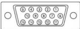
| No. | Function No. Function | ||
| 1 | Red video signal input 9 +5V | ||
| 2 | Green video signal input 10 GND | ||
| 3 | Blue video signal input 11 N.C. | ||
| 4 | N.C. 12 DDC data | ||
| 5 | GND 13 Hsync signal input | ||
| 6 | GND for red video signal 14 V | sync | signal input |
| 7 | GND for green video signal 15 | DDC | clock |
| 8 | GND for blue video signal | ||
Mounting Precautions (For SHARP dealers and service engineers)
- When installing, removing or moving the monitor, ensure that this is carried out by at least 2 people. (PN-HW861/PN-HW751: at least 3 people.)
- Be sure to use a wall-mount bracket designed or designated for mounting the monitor.
- This monitor is designed to be installed on a concrete wall or pillar. Reinforced work might be necessary for some materials such as plaster / thin plastic board / wood before starting installation.
- This monitor and bracket must be installed on a wall which can endure at least 4 times or more the weight of the monitor. Install by the most suitable method for the material and the structure.
- To attach a VESA-compliant mounting bracket, use M6 screws that are 5/16 inch (8 mm) to 3/8 inch (10 mm) longer than the thickness of the mounting bracket.
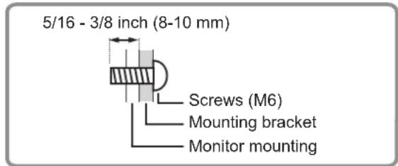
- Do not use an impact driver.
- When moving the monitor, be sure to hold it with the handles [PN-HW861/PN-HW751] or hold the parts marked by below [PN-HW651/PN-HW551/PN-HW501/PN-HW431]. Do not grasp the screen. This may cause product damage, failure, or injury.
[PN-HW651/PN-HW551/PN-HW501] [PN-HW431]
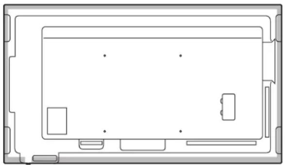
natural_image
Top-down schematic of a device layout with no text or symbols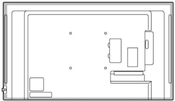
natural_image
Top-down line drawing of a room layout with furniture and fixtures (no text or symbols)• After mounting, please carefully ensure the monitor is secure, and not able to come loose from the wall or mount.
- Do not use any screw holes other than those for mounting brackets, located on the rear of the monitor, for installation.
SHARP®
SHARP CORPORATION
- Information on the Disposal of this Equipment and its Batteries
- CAUTION
- [PN-HW861/PN-HW751/PN-HW651]
- FOR CUSTOMERS IN U.K.
- IMPORTANT
- [PN-HW551/PN-HW501/PN-HW431]
- NOTE FOR USERS IN U.K.
- CONNECTING PLUG TO MAINS LEAD:
- CAUTION:
- SAFETY PRECAUTIONS
- WARNING:
- STABILITY HAZARD
- Especially for child safety
- The Power Cord
- Manual Scope
- LED Backlight
- Contents
- Supplied Components
- Part Names
- Connecting Peripheral Equipment
- ! Caution
- TIPS
- RS-232C input terminal
- LAN terminal
- D-sub input terminal
- Audio input terminal
- Audio output terminals
- USB port
- Connecting the Power Cord
- Binding Cables
- !Caution
- Attaching the USB flash drive cover
- Insert the USB flash drive into the USB port.
- Attach the USB flash drive cover and secure with the provided screw (x1).
- Attaching the logo sticker
- Removing the Handles (PN-HW861/PN-HW751 only)
- Preparing the Remote Control Unit
- Installing the batteries
- Remote control operation range
- Remote control sensor out
- Remote control sensor in
- Turning Power On/Off
- Turning on the main power
- ■Operation mode
- ■Date/time setting
- Basic Operation
- HDMI
- Numeric input buttons
- MUTE
- MODE (Color mode selection)
- VOLUME +/- (Volume adjustment)
- INFORMATION
- FUNCTION
- ENTER
- FREEZE
- Buttons for MEDIA PLAYER or operating the HDMI-connected device
- ID SET
- OPTION
- SIZE (Screen size selection)
- PIP/PbyP
- BRIGHT +/- (Brightness adjustment)
- INPUT (Input mode selection)
- MENU
- Cursor
- RETURN
- ■Switching the screen size
- Using Media Player
- ■ Supported formats
- Video files
- Playing files
- ■ Select the type of file to be played
- ■ Playing files
- ■ To stop play
- Auto playback
- ■ Preparations
- ■ Auto playback of files
- ■ To stop auto play
- Playing files using the SCHEDULE function
- Operations during play
- Menu Items
- Displaying the menu screen
- ■Example of operation
- ■Menu screen display
- Menu item details
- PICTURE
- COLOR MODE
- ADVANCED
- SIZE
- WHITE BALANCE
- PRESET
- USER
- NR
- ACTIVE CONTRAST
- GAMMA
- HDMI RGB INPUT RANGE
- BRIGHT
- BLACK LEVEL
- CONTRAST
- COLORS
- TINT
- SHARPNESS
- SCREEN
- AUTO (D-SUB)
- CLOCK (D-SUB)
- PHASE (D-SUB)
- H-POS (D-SUB)
- V-POS (D-SUB)
- RESET
- OPERATION MODE
- POWER SAVE MODE
- OFF IF NO OPERATION
- POWER MANAGEMENT
- NO SIGNAL AUTO INPUT SEL.
- AUTO PLAY
- MONITOR BUTTONS LOCK
- REMOTE CONTROL LOCK
- THERMAL SENSOR SETTING
- LED
- INFORMATION
- ALL RESET
- ■SCHEDULE
- ON/OFF
- ON TIME
- OFF TIME
- REPEAT MODES
- INPUT
- Adjustments for computer screen display
- ■Automatic adjustment
- ■Screen display for adjustment
- Opening the adjustment pattern
- Controlling the Monitor with a computer (RS-232C)
- Computer connection
- Communication conditions
- Communication procedure
- ■Command format
- ■Response code format
- ■Communication interval
- RS-232C command table
- How to read the command table
- Controlling the Monitor with a computer (LAN)
- ■To set on the monitor
- VIEW NETWORK SETTINGS
- DHCP CLIENT
- IP ADDRESS
- SUBNET MASK
- DEFAULT GATEWAY
- SET
- Command-based control
- Connect the computer to the monitor.
- Send commands to control the monitor.
- Disconnect the connection with the monitor and quit the function.
- Troubleshooting
- There is no picture or sound.
- Remote control does not work.
- Sound from left and right speakers is reversed.
- Sound is heard from only one side.
- There is a picture but no sound.
- Unstable video.
- The video from the HDMI input terminal does not appear properly.
- The video from D-Sub input terminal does not appear correctly.
- Control buttons do not work.
- There is no picture.
- The input mode changes automatically.
- When "AUTO DIMMING" is displayed.
- The monitor makes a cracking sound.
- The Power LED is flashing in red and green alternately. When “TEMPERATURE” is displayed in the corner of the screen.
- Specifications
- ■DDC (plug and play)
- ■HDMI input terminal pins
- ■RS-232C input terminal pins
- ■D-sub input terminal pins
- Mounting Precautions (For SHARP dealers and service engineers)
- SHARP®
- SHARP CORPORATION
Brand : SHARP
Model : PN-HW501T
Category : Whiteboard