
SCxn305d - Instant water heater and boiler DIMPLEX - Free user manual and instructions
Find the device manual for free SCxn305d DIMPLEX in PDF.


| Product Type | Unvented Hot Water Cylinder |
| Brand | Dimplex |
| Model | SCxn305d |
| Capacity | 305 Liters |
| Weight (empty) | 59 kg |
| Dimensions (Height x Diameter) | 1620 mm x 574 mm |
| Maximum Operating Pressure | 6 bar |
| Maximum Water Temperature | 70°C |
| Maximum Heating Water Temperature (Indirect) | 95°C |
| Insulation | 60 mm PU Foam (GWP=1, ODP=0) |
| Inner Cylinder Material | Duplex Stainless Steel |
| Outer Cylinder Material | Dove Grey Leather Grain Coated Steel |
| Connections (Cold/Hot Water) | 22 mm Stainless Steel |
| Heating Element | Immersion Heater (Direct Electric) |
| Heat Loss | 2.88 kWh/24h |
| Heat-Up Time (Direct Electric) | Approximately 313 minutes |
| Safety Features | Pressure Reducing Valve, Expansion Relief Valve, Temperature & Pressure Relief Valve |
| Anode Requirement | No (sacrificial anode not required) |
| Guarantee (Inner Cylinder) | 25 Years |
| Guarantee (Immersion Heaters) | 2 Years (excluding limescale effects) |
| Guarantee (Other Components) | 5 Years (excluding expansion vessel membrane) |
Frequently Asked Questions - SCxn305d DIMPLEX
User questions about SCxn305d DIMPLEX
0 question about this device. Answer the ones you know or ask your own.
Ask a new question about this device
Download the instructions for your Instant water heater and boiler in PDF format for free! Find your manual SCxn305d - DIMPLEX and take your electronic device back in hand. On this page are published all the documents necessary for the use of your device. SCxn305d by DIMPLEX.
USER MANUAL SCxn305d DIMPLEX
Please note that some of the contact details on this PDF document may not be current.
Please use the following details if you need to contact us:
Telephone: 0844 879 3588 Email: customer.services@gdcgroup.co.uk
The customer support section of our website also features a wide range of information which may be of use to you and is available 24 hours a day. It includes:
- Operating and installation instructions
- Easy 'How to use' guides for storage heaters
• Service and repairs
• Where to buy our products
• Literature downloads
• Heating requirement calculator
Visit - www.dimplex.co.uk/support
natural_image
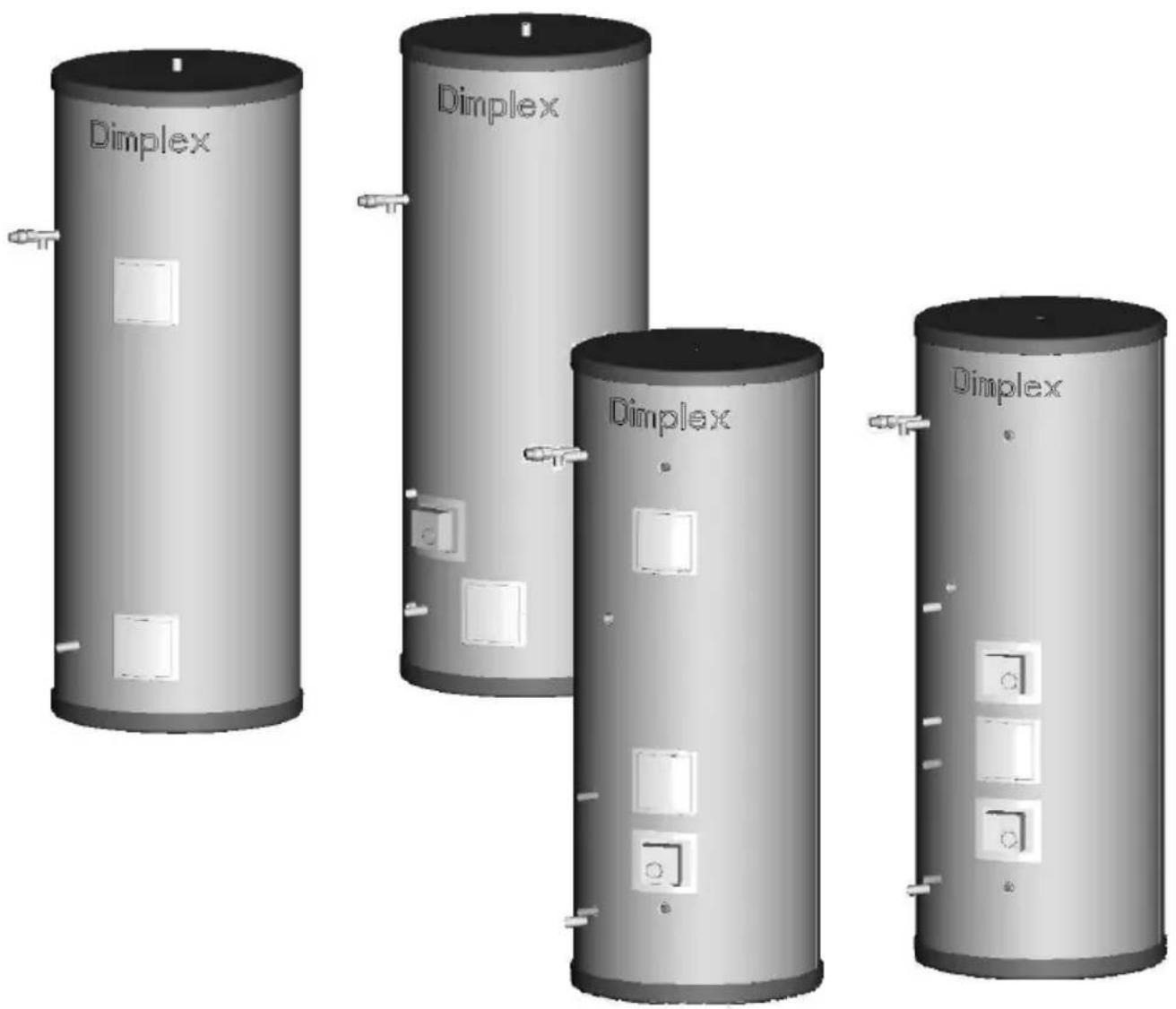
Four identical Dimplex cylindrical tanks with internal circuitry and switches, shown from different angles (no text or symbols on the tanks themselves)Unvented hot water cylinder - SCxn...d/i, SCxn...sd/si
Installation and operating instructions
0 Overall view
SCxn80/130/150/175/215/255/305d
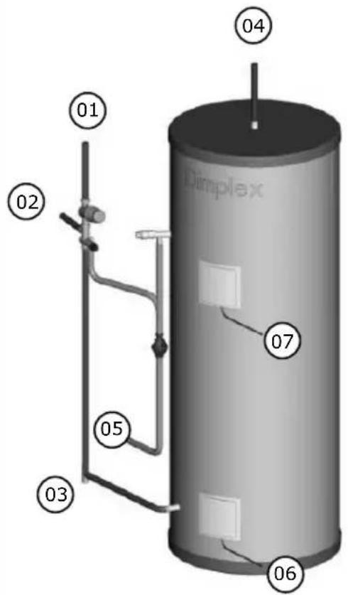
Standard SCxn cylinder
SCxn80/130/150/175/215/255/305i
Reference Description
| 1 | Cold water mains supply |
| 2 | Balanced cold water supply |
| 3 | Cylinder drain point |
| 4 | Hot water supply |
| 5 | Discharge arrangement |
| 6 | Off peak immersion supply |
| 7 | Boost immersion supply |
| 8 | Indirect heating flow |
| 9 | Indirect heating return |
| 10 | Indirect heating twin thermostat |
| 11 | Indirect heating motorised two port valve |
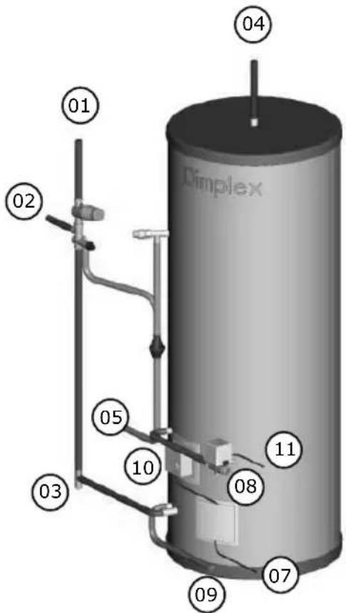
Figure 1 - Overall view of proposed installation sequence SCxn...d/i
SCxn175/215/255/305sd
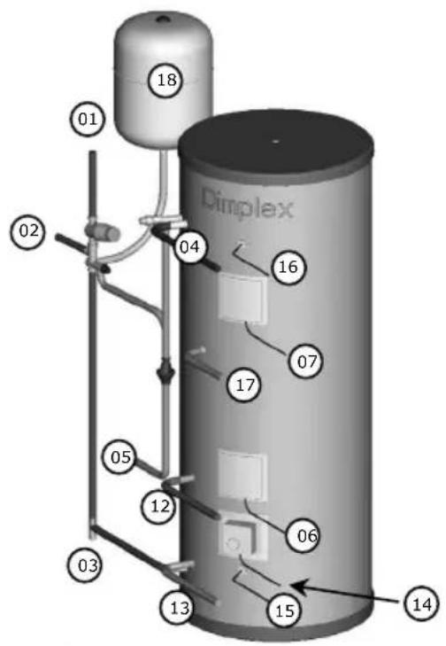
Solar SCxn cylinder
SCxn175/215/255/305si
Reference Description
| 1 | Cold water mains supply |
| 2 | Balanced cold water supply |
| 3 | Cylinder drain point |
| 4 | Hot water supply |
| 5 | Discharge arrangement |
| 6 | Off peak immersion supply |
| 7 | Boost immersion supply |
| 8 | Indirect heating flow |
| 9 | Indirect heating return |
| 10 | Indirect heating twin thermostat |
| 11 | Indirect heating motorised two port valve |
| 12 | Solar heating flow |
| 13 | Solar heating return |
| 14 | Solar heating twin thermostat |
| 15 | Solar cylinder sensor BOTTOM |
| 16 | Solar cylinder sensor TOP |
| 17 | Secondary return |
| 18 | Expansion vessel |
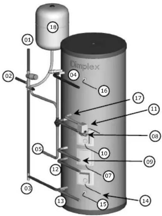
Figure 2 - Overall view of proposed installation sequence SCxn...sd/si
1 Contents
0 OVERALL VIEW 2
1 CONTENTS 4
2 BEFORE YOU START 5
GENERAL 5
COMPETENCE 5
HEALTH AND SAFETY 5
RISK ASSESSMENT 6
3 SCOPE OF DELIVERY 6
4 PRODUCT FEATURES AND DESCRIPTIONS 7
5 INSTALLATION 9
5.1 GENERAL ADVICE 9
5.2 SITING CONSIDERATIONS 10
5.3 COLD WATER SUPPLY AND DISCHARGE PIPE WORK 10
5.4 HOT WATER OUTLET 12
5.5 IMMERSION HEATER 12
5.6 INDIRECT HEATING LOOP 13
5.7 SOLAR LOOP 14
5.8 SECONDARY RETURN 15
5.10 INSTALLATION EXPANSION VESSEL 15
5.11 WIRING SCHEMATIC AUXILIARY LOOP 16
5.12 WIRING SCHEMATIC SOLAR LOOP 19
5.13 SOLAR SENSOR INSTALLATION 19
6 COMMISSIONING 21
6.1 SCXN ... D/I RANGE 21
6.2 SCXN ... SD/SI RANGE 21
7 OPERATION 22
7.1 WATER TEMPERATURE DIRECT ELECTRIC HEATING 22
7.2 WATER TEMPERATURE AUXILIARY HEATING 23
8 MAINTENANCE 23
9 TROUBLESHOOTING 24
10 TECHNICAL DATA 25
10.1 SCXN ... D/I 25
10.2 SCXN ... SD/SI 26
2 Before you start
General
Thank you for choosing a Dimplex product. We ensure you that every effort was made at design, manufacture and delivery stages of this product to meet your expectations. We ensure you of our best possible support throughout the product's lifespan.
As part of ongoing product development and improvement Dimplex reserves the right to undertake changes to the product without prior notice. Great care has been taken to ensure this manual was correct at the time of print. Should you however discover any issues with the information contained therein please do not hesitate to contact your vendor.
We strongly recommend you read the whole contents of this manual before commencing the work.
Competence
Dimplex products have been designed and manufactured to the current relevant dards and under stringent quality control. It is therefore imperative that the product is only installed by a:
- trained and
- competent
person as defined in the relevant regulations. Dimplex does not accept any liability for damage done to persons or property resulting from undue handling and usage of this product.
All regulations current at the time of installation are to be considered alongside the content of this manual as they form the code of best practice.
The guarantee of this product is linked to the ability of proving that the product was installed, commissioned and maintained:
- by a competent person
- in accordance with Dimplex instructions and the current relevant regulations and legislation
- the product being registered with Dimplex at the time of installation using the form in the Dimplex On Site Guide
- records showing the date of maintenance in accordance with the maintenance schedule as detailed in the On Site Guide
Health and Safety
The installation of this product is subject to the Health and Safety at Work Act. It is your responsibility to ensure that the transport, storage, installation and operation of the product is carried out in a safe manner.
Dimplex will not accept any liability due to damage caused to people or property resulting from negligence or not adhering to the relevant Health and Safety practises.
Risk assessment
The compilation of a risk assessment is strongly recommended before installing the product. The following areas require particular consideration in addition to the information required by the Health and Safety at Work Act.
- scalding: where appropriate or required by law a thermostatic mixing valve is to be fitted to the hot water outlet of the cylinder
- explosion: the unit is fully equipped with all relevant safety equipment to comply with current regulations. The correct design and function has been verified by independent third party testing. The correct application thereof is the responsibility of the competent installer.
- water borne organisms (i.e. Legionella): if applicable a risk assessment should be carried out following the recommendations outlined in the Approved Code of Practise L8.
- the user preference must be considered when commissioning the system, in particular when adjusting the solar and auxiliary system temperature and timer settings.
3 Scope of delivery
Please check the contents and condition of your delivery before signing the delivery documentation. Contact your supplier immediately for any missing or damaged components. Claims for missing or damaged parts after signing for the delivery will not be accepted.
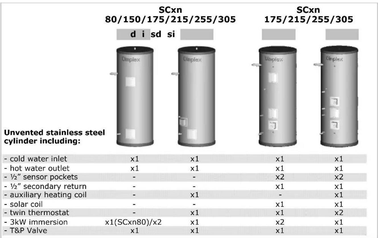
| SCxn...d | SCxn...i | SCxn...sd | SCxn...si | ||
| Expansion vessel:18 l: 175 l, 215 l24 l: 255 l, 305 l |  | - | - | x1 | x1 |
| - | - | ||||
| Expansion vessel fixing kit | 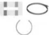 | - | - | x1 | x1 |
Inlet control group 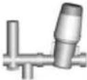 | Pres. red.Pres. rel. | 2bar6bar | 2bar6bar | 3bar6bar | 3bar6bar |
| Tundish15mm - 22mm |  | x1 | x1 | x1 | x1 |
| Two port motorised valve 22mm |  | - | x1 | - | x1 |
| Instructions x1 |  | x1 | x1 | x1 | |
| Benchmark card x1 |  | x1 | x1 | x1 | |
Figure 3 - Scope of delivery
4 Product features and descriptions
The Dimplex ^® unvented stainless steel cylinder range incorporates many features to ensure the highest level of comfort in providing hot water while minimising energy requirements and environmental impact during manufacturing, operation and disposal.
The range covers storage volumes from 80 litres to 305 litres in various designs from direct electric heated units, indirect units to a range of units allowing the use of renewable energy sources such as solar thermal.
A complete list of features provided by the whole range of cylinders is given in Figure 4.
| Feature | SCxn | |||||||||
| d80-305 | i | si175-305 | sd175-305 | |||||||
| 80 | 130 | 150 | 175 | 215 | 255 | 305 | ||||
| Materials- inner cylinder- outer cylinder- inlet/outlet- coils- insulation | Duplex stainless steelDove grey leather grain coated steelStainless steelCorrugated stainless steel60mm PU foam (GWP=1, ODP=0) | |||||||||
| Maximum operating conditions- potable water temperature- heating water temperature- operating pressure | 70°C95°C6bar | |||||||||
| Cold water supply- minimum dynamic pressure- maximum pressure- minimum flow rate | 1.5bar25bar15 l/min | |||||||||
| Connections- cold water inlet- hot water outlet- secondary return- coil flow and return- sensor pocket | 22mm stainless steel22mm stainless steel 12 "F BSP22mm stainless steel 12 "F BSP | |||||||||
| Coil specification- surface area [m2]- rating [kW] | - | 0.3 | 0.5 | 0.75 | 0.75/1.1 | |||||
| - | 7 | 14 | 17 | 17/- | ||||||
| Immersion heater 1/ | 2 | 1 | 1 | |||||||
| Thermostatic control- direct input- indirect input | - integral immersion heater thermostat and cut out- external twin thermostat and cut out | |||||||||
| Safety components- pressure reducing valve and strainer- expansion relief valve- temperature and pressure relief valve- factory pressure test | 2bar6bar7bar / 90°C10bar | 3bar6bar7bar /90°C10bar | ||||||||
| Other features Water inlet diffuser | - prevents cold and hot water from mixingWater outlet sloped - improves stratification during draw off and reduces heat lossLight weight - easy handlingNo anode - reduced service requirements | |||||||||
| Approvals KIWA | BBA | |||||||||
| Guarantee- inner cylinder- immersion heaters- other components | 25 years2 years - excluding the effects of lime scale5 years - excluding expansion vessel membrane pressure | |||||||||
Figure 4 - Product features
5 Installation
5.1 General advice
Please read the following section carefully before commencing installation. If in any doubt, please call the appropriate help desk. Disregarding the instructions given in this manual in its entirety and any relevant regulations, standards and codes of practice will void the guarantee of this product.
Please note: the following instructions are structured in such a way that individual steps are described. Not all steps will apply to all products. Figure 5 shows which steps apply to which cylinder types.
| Chapter | Content | Cylinder type SCxn | |||
| d | i | sd | si | ||
| 5.1 | General advice | ✓ | |||
| 5.2 | Siting considerations | ✓ | |||
| 5.3 | Cold water supply and discharge pipe work | ✓ | |||
| 5.4 | Hot water outlet | ✓ | |||
| 5.5 | Immersion heater | ✓ | |||
| 5.6 | Indirect heating loop | x | ✓ | x | ✓ |
| 5.7 | Solar loop | x | ✓ | ||
| 5.8 | Secondary return | x | ✓ | ||
| 5.9 | Charging of internal expansion bubble | ✓ | x | x | |
| 5.10 | Installation expansion vessel | optional | ✓ | ||
| 5.11 | Wiring schematic auxiliary loop | x | ✓ | x | ✓ |
| 5.12 | Wiring schematic solar loop | x | ✓ | ||
| 5.13 | Solar sensor installation | x | ✓ | ||
Figure 5 - Chapter reference
Handling – depending on the size of the unit and access to its installation location consideration must be given to the handling of the unit. Please note that handling, installation and use of this product is subject to the Health and Safety at Work Act.
If the unit is not installed immediately, it should remain in its protective packaging with all pipe protectors/end caps applied to prevent damage and dirt deposit inside the cylinder and the coils.
Pipe work – the pipe runs should be executed as short as possible, unused pipe work should be removed and all remaining pipe work should be lagged in accordance with regulatory requirements to prevent heat loss and the formation of condensation.
Taps and fittings – all taps and fittings incorporated in the unvented system should have a rated operating pressure of 6 bar or above.
5.2 Siting considerations
When choosing a suitable location for the cylinder the following aspects should be considered:
- structural integrity
- access for installation, operation, maintenance and replacement
- routing of discharge pipe work
- access to water mains supply, hot and cold water distribution pipe work
- access to suitable electricity supply
- location in relation to remaining system components such as auxiliary and solar heating system
- frost protection
The Dimplex SCxn cylinder range is designed to be floor standing, vertically mounted, indoors and in a frost free environment. The cylinder may be located on any flat and level surface, provided it is sufficiently robust to support the weight of the cylinder when full of water (see chapter 10).
The position and orientation of the cylinder should be such that easy access is provided for servicing the controls and replacing the immersion heater should the need arise. Ensure that no pipe work hinders any work to be carried out on the various cylinder components.
Particular care must be taken when placing the cylinder in a garage or outbuilding. All exposed pipe work must be correctly insulated to avoid frost damage. If required the occurrence of frost has to be avoided by means of heating the space in which the cylinder is located.
5.3 Cold water supply and discharge pipe work
The required operating conditions of the Dimplex SCxn cylinder range are summarised in Figure 4. The following instructions have to be followed when installing the cold water mains supply to the cylinder.
1 The cold water supply to the cylinder must come directly from the cold water mains after the mains stop valve to the property.
2 The inlet group supplied with the cylinder contains a line strainer, pressure reducing valve, pressure relief valve, check valves, balanced cold water supply port and a connection point for the expansion vessel (required for SCxn solar only).
3 The cold water inlet pipe work should have at least an inside diameter of 19mm and meeting the requirements of the water regulations for the supply of wholesome water.
4 The discharge pipe work from the expansion relief valve must be installed constantly falling to an open point of discharge. It is recommended to combine it with the discharge of the temperature and pressure relief valve as illustrated in Figure 6.
When completing the installation of the discharge pipe work ensure the valve itself is secured by tightening the screw on the side of the assembly. Loosening the screw allows the best possible orientation of the valve.
5 It is recommended to install a drain valve in the lowest point of the cold water feed to the cylinder. This allows the cylinder to be drained in a controlled manner should this become necessary.
Note: Between the inlet group and the cold water inlet on the cylinder NO isolating device should be fitted as by doing so important safety devices could be isolated!
6 The temperature and pressure relief valve must be discharged into the tundish. The sizing of the discharge pipe work is regulated through building regulation G3. An extract is shown in Figure 6.
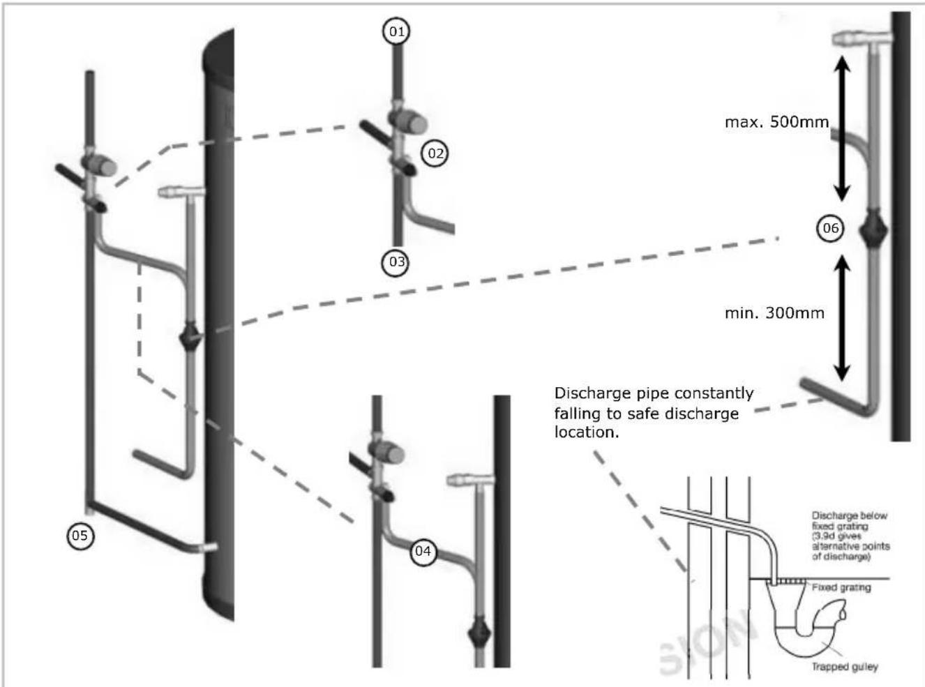
| Valve outlet size[-] | Minimum size of discharge pipe before tundish[mm] | Minimum size of discharge pipe after tundish[mm] | Maximum allowed length of pipe after tundish[m] | Length to be subtracted for each elbow or bend[m] |
| G1/2 (Dimplex SCx temperature and pressure relief valve) | 15 | 22 | 9 | 0.8 |
| 28 | 18 | 1.0 | ||
| 35 | 27 | 1.4 | ||
| G3/4 | 22 | 28 | 9 | 1.0 |
| 35 | 18 | 1.4 | ||
| 42 | 27 | 1.7 | ||
| G1 | 28 | 35 | 9 | 1.4 |
| 42 | 18 | 1.7 | ||
| 54 | 27 | 2.3 |
Figure 6 - Cold water supply and discharge pipe work installation
5.4 Hot water outlet
The hot water pipe work is to be directly connected to the how water outlet connections of the cylinder as indicated in Figures 1 and 2.
Should a thermostatic mixing valve be required the valve is to be installed following the manufacturers instructions. When fitting the thermostatic mixing valve ensure that none of the safety relevant devices of the unit can be isolated (see 5.3).
It is recommended to insulate the hot water pipe work from the cylinder to the outlets to reduce the energy requirements for providing hot water.
5.5 Immersion heater
The immersion heater has to be connected in accordance with IEE Wiring Regulations and the installer carrying out the work has to be suitably qualified. It must be connected through a double pole isolating switch or suitable controller which must have a contact separation of at least 3mm in all poles. The wiring diagram for the immersion heater is shown in Figure 7. For further details please see instructions provided with immersion heater.
The immersion heater incorporates an independent non-self resetting over temperature cut-out. Should the over temperature cut-out operate, the rest pin will be pushed upwards, and become level or slightly proud of the cover at the position marked "Safety". Use a suitable sized implement to reset the pin by pushing it hard into its original position.
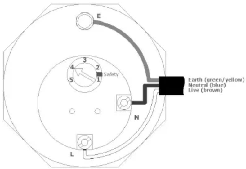
Figure 7 - Wiring diagram immersion heater

Note: The cylinder must be filled with water before switching on the immersion heater. Failure to do so will damage the element and void any guarantee on the product.
5.6 Indirect heating loop
The indirect heating source can be connected to the cylinder in various ways as described by the chosen control system supplier. The wiring and installation principles for two typical integration methods are detailed in chapter 5.11.
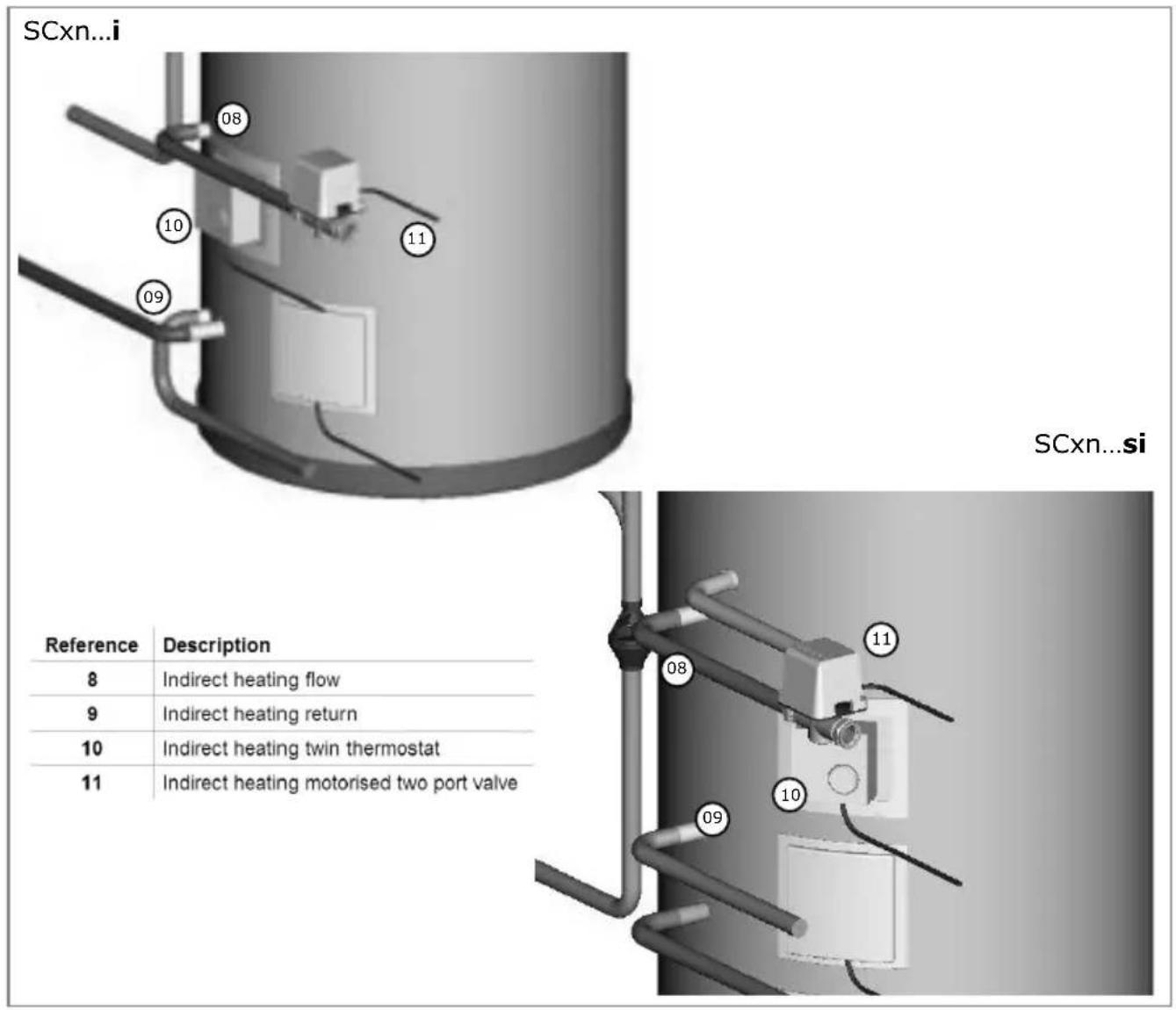
Figure 8 - indirect heating loop installation
To conform with building regulations it is imperative that the motorised two port valve is installed in the indirect heating loop and connected into the control circuit as required.
The port connections for the indirect heating flow and return are identified in Figure 1 for the SCxn...i range and in Figure 2 for the SCxn...si range.
Should the flow connection be the highest point in the indirect heating loop an adequate device for de-aeration has to be installed. Equally, should the return connection be the lowest point in the indirect heating loop, a suitable drain device should be installed in the lowest point.
When installing the motorised two port valve ensure the direction of flow is adhered to as marked on the body of the device. Connecting the control loop ensure the correct thermostat on the cylinder is chosen for the respective loop.
The fittings used to connect to the cylinder must be suitable for stainless steel. Not all push fit fittings can be used – please check with your supplier. Should compression fittings be used ensure that the connection is not being over-tightened, always countering the force with a second spanner.
5.7 Solar loop
The solar loop has to be completely installed:
- in metal pipe work
- insulated with high temperature insulation
- connected with compression fittings only (or other means which are suitable for solar)
SCxn...sd / SCxn...si
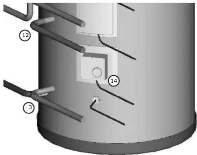
| Reference | Description |
| 12 | Solar heating flow |
| 13 | Solar heating return |
| 14 | Solar heating twin thermostat |
Figure 9 - Solar loop installation
The wiring schematic for the solar loop is detailed in chapter 5.12. Please note: the solar loop does not require a motorised two port valve as long as:
- the Dimplex SOLPU1/2 pump unit is being used (non return valves in flow and return)
- the cylinder is located lower than the solar panels
- all other connection requirements in this manual are being adhered to
To conform with building regulations it is imperative that the solar circulation pump is installed in the solar loop through the twin thermostat and not directly from the solar control unit.
The port connections for the solar flow and return connections are identified in Figure 2 for the SCxn...sd and the SCxn...si range.
Should the flow connection be the highest point in the solar loop an adequate device for de-aeration has to be installed should the system not be commissioned using a flush a fill pump. Equally, should the return connection be the lowest point in the solar loop, a suitable drain device should be installed in the lowest point.
5.8 Secondary return
A 12 " boss is provided on the SCxn...sd/si cylinder range to connect a secondary return loop to avoid:
- stagnant water in long pipe runs
- long waiting times at draw off point for hot water
- undue water wastage
To minimise the energy consumption of the secondary return circuit and to ensure reliable operation it is important to consider:
- the control of the circulation pump to be time and temperature controlled
- the secondary return circuit pipe work to be insulated
- the secondary return pump to be of suitable material
The location of the secondary return connection on the cylinder is highlighted in Figure 2.
5.10 Installation expansion vessel
Optional for standard SCxn d/i cylinders, mandatory for solar SCxn d/I cylinders.
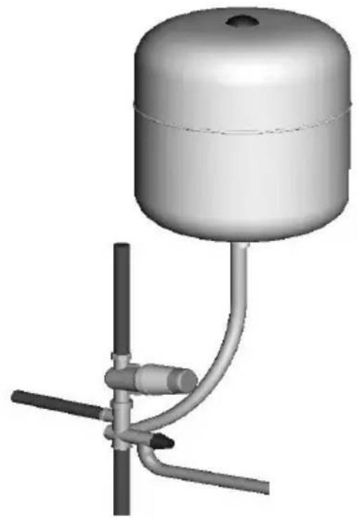
The expansion vessel can be connected directly to the cold water inlet group utilising the flexible hose supplied with the vessel. It is important not to install any isolating devices between the vessel and the cold water inlet group.
Further it is recommended to mount the vessel higher than the cylinder to avoid having to drain the cylinder when maintaining and replacing the expansion vessel. The connection of the expansion vessel to the inlet group is shown in Figure 10.
natural_image
3D rendering of a cylindrical water pump mounted on a vertical pole with tubing (no text or symbols visible)Figure 10 – Installation expansion vessel
(optional for standard SCxn d/i cylinders, mandatory for solar SCxn d/I cylinders)

It is important to check the pre-charge pressure of the expansion vessel membrane before filling the cylinder. The pre-charge should be >2bar.
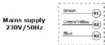
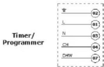
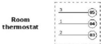
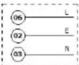
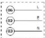
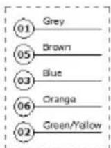
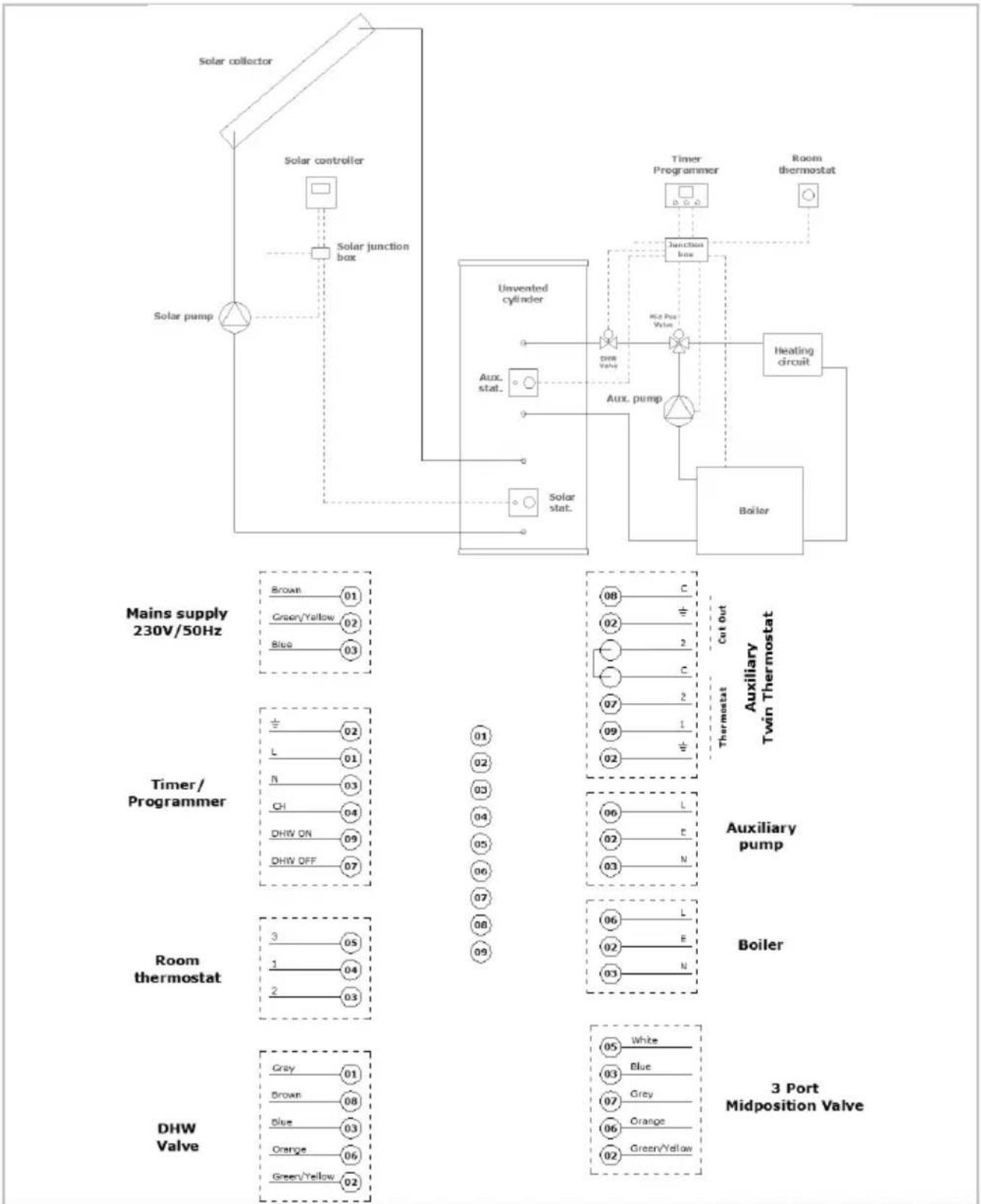
5.11 Wiring schematic auxiliary loop
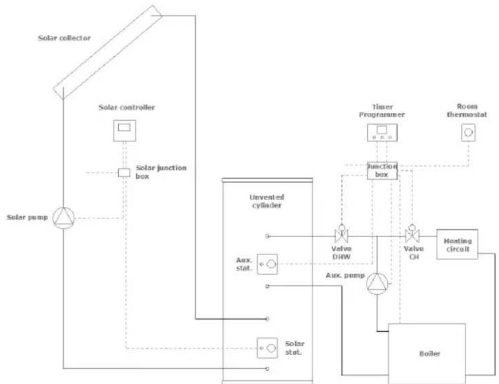
The auxiliary heating system can be interfaced with the Dimplex SCxn cylinder in various. Two common examples are given in Figures 11 and 12.

Before adapting one of the proposed systems ensure the system is compatible with the remaining control equipment installed in the system.
flowchart
graph TD
    A["Solar collector"] --> B["Solar controller"]
    B --> C["Solar junction box"]
    C --> D["Solar pump"]
    D --> E["Unvented cylinder"]
    E --> F["Aux. stat."]
    E --> G["Solar stat."]
    F --> H["Valve DHW"]
    G --> I["Aux. pump"]
    H --> J["Function box"]
    I --> K["Valve OH"]
    J --> L["Timer Programmer"]
    K --> M["Room thermostat"]
    L --> N["Heating circuit"]
    M --> O["Boiler"]
flowchart
graph TD
    A["Room thermostat"] --> B["3"]
    A --> C["1"]
    A --> D["2"]
    B --> E["05"]
    C --> F["04"]
    D --> G["03"]
flowchart
graph TD
    A["06"] --> B["C"]
    C["02"] --> D["+"]
    E[" "] --> F["2"]
    G[" "] --> H["C"]
    I["√*"] --> J["2"]
    K["07"] --> L["1"]
    M["02"] --> N["*"]
    style A fill:#fff,stroke:#000
    style C fill:#fff,stroke:#000
    style E fill:#fff,stroke:#000
    style G fill:#fff,stroke:#000
    style K fill:#fff,stroke:#000
    style M fill:#fff,stroke:#000
    subgraph Auxiliary Twin Thermostat
        B
        D
        H
        J
        L
        N
    end
Thermostat Cut Out
Auxiliary Twin Thermostat
Auxiliary pump
Boiler
CH
Valve
Figure 11 - Auxiliary loop integration 2x motorised two port valve
flowchart
graph TD
    A["Solar collector"] --> B["Solar controller"]
    B --> C["Solar junction box"]
    C --> D["Solar pump"]
    D --> E["Unvented cylinder"]
    E --> F["Aux. stat."]
    F --> G["Solar stat."]
    G --> H["Hotel Valve"]
    H --> I["Aux. pump"]
    I --> J["Room thermostat"]
    J --> K["Boiler"]
    K --> L["Heating circuit"]
    L --> M["Timer Programmer"]
    M --> N["Room thermostat"]
    N --> O["Auxiliary twin thermostat"]
    O --> P["Auxiliary pump"]
    P --> Q["Boiler"]
    Q --> R["3 Port Midposition Valve"]

    style A fill:#f9f,stroke:#333
    style B fill:#ccf,stroke:#333
    style C fill:#cfc,stroke:#333
    style D fill:#fcc,stroke:#333
    style E fill:#cff,stroke:#333
    style F fill:#ffc,stroke:#333
    style G fill:#cfc,stroke:#333
    style H fill:#fcc,stroke:#333
    style I fill:#ffc,stroke:#333
    style J fill:#cfc,stroke:#333
    style K fill:#fcc,stroke:#333
    style L fill:#cfc,stroke:#333
    style M fill:#ccf,stroke:#333
    style N fill:#cfc,stroke:#333
    style O fill:#fcc,stroke:#333
    style P fill:#ffc,stroke:#333
    style Q fill:#cfc,stroke:#333
    style R fill:#fcc,stroke:#333
    style S fill:#cfc,stroke:#333
    style T fill:#fcc,stroke:#333
    style U fill:#cfc,stroke:#333
    style V fill:#fcc,stroke:#333
    style W fill:#cfc,stroke:#333
    style X fill:#fcc,stroke:#333
    style Y fill:#cfc,stroke:#333
    style Z fill:#fcc,stroke:#333
Figure 12 - Auxiliary loop integration 1x motorised two port valve and mid-position valve
5.12 Wiring schematic solar loop
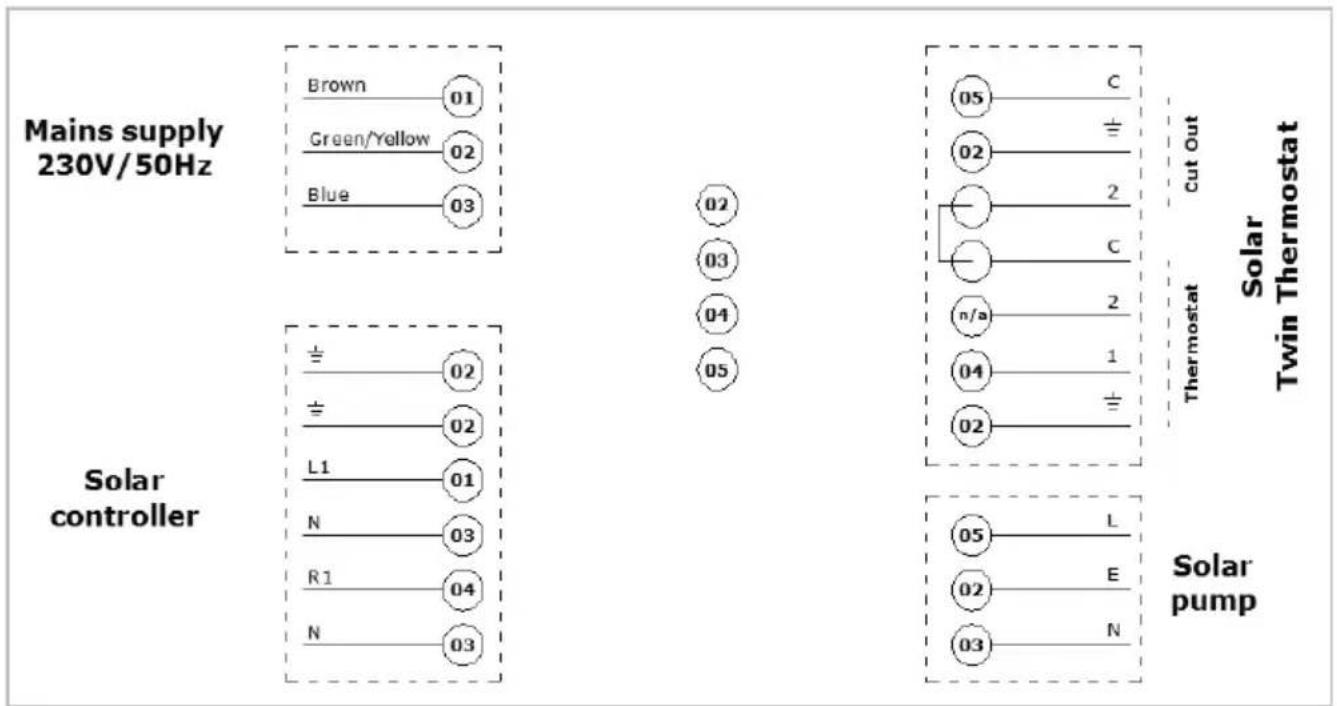
The integration of the Dimplex solar SCxn cylinder is shown in Figures 11 and 12. The wiring schematic for the solar loop is shown in Figure 13.
flowchart
graph TD
    A["Mains supply 230V/50Hz"] --> B["Brown 01"]
    A --> C["Green/Yellow 02"]
    A --> D["Blue 03"]
    E["Solar controller"] --> F["± 02"]
    E --> G["± 02"]
    E --> H["L1 01"]
    E --> I["N 03"]
    E --> J["R1 04"]
    E --> K["N 03"]
    L["Solar pump"] --> M["05 C"]
    L --> N["02 ±"]
    L --> O["2"]
    L --> P["2 C"]
    L --> Q["n/a 2"]
    L --> R["04 1"]
    L --> S["02 ±"]
    T["Solar Twin Thermostat"] --> U["cut Out"]
    T --> V["Thermostat"]
    T --> W["Solar pump"]
Figure 13 - Solar loop integration
5.13 Solar sensor installation
The Dimplex solar SCxn range cylinders allow for the installation of two sensors. The lower sensor is required to control the solar circulation pump. The upper sensor is for information only to indicate the actual available hot water temperature.
Two 12 " sensor pockets are supplied with the pump unit. The sensor pockets are to be used to install the sensors in the cylinders.
The location of the sensor bosses is indicated in Figure 14, also showing the methodology of installing the sensor into the sensor pocket. A suitable sealant is to be used such as Loctite 577.
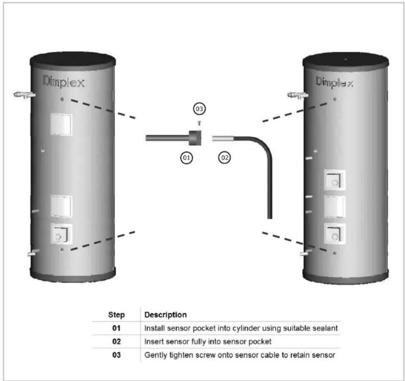
Figure 14 - Solar sensor boss positions and sensor installation
6 Commissioning
The following commissioning procedure only details the required steps to be taken for the potable water loop and not for the direct heating, auxiliary or solar loops. Please refer to relevant manuals for these operations.
6.1 SCxn ... d/i range
☐ 1 Check all connections and joints to ensure they have been tightened and secured correctly.
☐ 2 Before turning on the mains supply to the cylinder a hot water tap should be opened, preferable on the same floor or the floor below where the cylinder is located.
☐ 3 Turn on the supply to the cylinder and fill until water runs from the open hot water tap.
☐ 4 Turn off the mains supply to the cylinder and wait for the water to stop running from the hot water tap.
☐ 5 Operate the temperature and pressure relief valve until water stops flowing.
☐ 6 Close the hot water tap and temperature and pressure relief valve.
☐ 7 Connect an air pump to the Schrader valve (valve with blue cap) located on the pressure reducing valve (inlet group).
☐ 8 Pump air into the Schrader valve until a pressure of 1 bar is reached.
☐ 9 Remove the pump and replace the blue cap.
☐ 10 Turn the mains supply back on and bring the cylinder up to working pressure.
☐ 11 Check all joints for leaks, even those not having been altered especially when replacing a vented cylinder.
☐ 12 Open temperature and pressure relief valve to ensure proper discharge and check after closing that valve is not dripping.
☐ 13 Open pressure relief valve to ensure proper discharge and check after closing that valve is not dripping.
☐ 14 Check all shower outlets, toilet cisterns and other draw off points for leaks or dripping (especially when replacing a vented unit).
☐ 15 Open all water outlets to purge air from pipe work and ensure proper operation.
☐ 16 Adjust timer programmer and cylinder thermostat settings in accordance with client requirements.
☐ 17 Instruct user in the operation of the unit and hand over manuals and benchmark card, advising the owner of annual service requirement.
6.2 SCxn ... sd/si range
☐ 1 Check all connections and joints to ensure they have been tightened and secured correctly.
☐ 2 Before turning on the mains supply to the cylinder a hot water tap should be opened, preferable on the same floor or the floor below where the cylinder is located.
☐ 3 Check the pre-charge in the expansion vessel and ensure it is at least 2bar. Note actual pressure on label on expansion vessel.
☐ 4 Turn on the supply to the cylinder and fill until water runs from the open hot water tap.
□ 5 Close the hot water tap.
☐ 6 Check all joints for leaks, even those not having been altered especially when replacing a vented cylinder.
☐ 7 Open temperature and pressure relief valve to ensure proper discharge and check after closing that valve is not dripping.
☐ 8 Open pressure relief valve to ensure proper discharge and check after closing that valve is not dripping.
☐ 9 Check all shower outlets, toiler cisterns and other draw off points for leaks or dripping (especially when replacing a vented unit).
☐ 10 Open all water outlets to purge air from pipe work and ensure proper operation.
☐ 11 Adjust timer programmer and cylinder thermostat settings in accordance with client requirements.
☐ 12 Instruct user in the operation of the unit and hand over manuals and benchmark card, advising the owner of annual service requirement.
7 Operation
Once the system has been fully commissioned, no user interference should be required to fully enjoy the comfort and benefits of the Dimplex SCxn hot water cylinder.
The hot water temperature can be set to various requirements. Ideally it should be around 60^ C. Higher temperature can cause tripping of the high limit thermostat, introduces more heat loss from the unit and increases the risk of scalding significantly.
When turning on a hot tap for the first time after a heat up period there might be a short surge of water. This is normal in unvented systems and does not constitute a fault. Sometimes the water may appear milky – this is due to very fine air bubbles in the water which will clear quickly.
7.1 Water temperature direct electric heating

Before removing the cover from immersion heater isolate appliance on isolating switch! Danger of electrical shock! Never enter immersion heater housing with blank metal objects!
Dial to adjust water temperature.
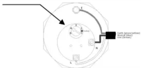
Figure 15 - Adjustment water temperature direct electric heating element
The hot water temperature achieved by the direct electric heating element can be adjusted by removing the cover from the immersion heater and adjusting the dial up or down as indicated in Figure 15.
7.2 Water temperature auxiliary heating
The water temperature achieved by the auxiliary heating system depends on the setting of the thermostat on:
- the cylinder AND
- the auxiliary heating source.
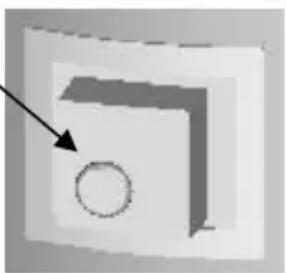
The adjustment at the cylinder is being carried out on the twin thermostat fitted to the cylinder as shown in Figure 16. The manual high limit re-set is behind the black screw.
Dial to adjust water temperature.
natural_image
Simple 3D diagram showing a square with an arrow pointing to a circle inside (no text or symbols)Figure 16 - Adjustment water temperature auxiliary source
8 Maintenance

The maintenance of this appliance must be carried out by a suitably qualified person only.
Isolate all electrical supplies from the unit before commencing work. Danger of electrical shock!
☐ 1 Draw some water from cold water tap and retain in container.
☐ 2 Isolate cold water mains supply from cylinder.
☐ 3 Briefly open temperature and pressure relief valve, assure safe discharge and check that valve is not dripping when closed.
☐ 4 Briefly open pressure relief valve, assure safe discharge and check that valve is not dripping when closed.
☐ 5 Open hot water tap and release remaining pressure from unit.
☐ 6 Note the set pressure of pressure reducing valve. Remove cartridge and clean strainer in water provided in container. Re-assemble pressure reducing valve ensuring the correct pressure is set.
☐ 7 Periodically the immersion heaters should be removed, cleaned and the unit flushed out. The immersion heater seal should be replaced when fitting the element to the cylinder.
☐ 8 Check electrical wiring connections and the condition of the cable of the immersion heater and the thermostat.
□ 9 Re-commission unit.
9 Troubleshooting
| Fault Cause Solution | ||
| A No water from hot water taps | A.1 Stop valve closedA.2 Strainer blockedA.3 Pressure reducing valve fitted against flow | A.1 Open stop valveA.2 Turn water supply off, clean strainer and re-commissionA.3 Re-fit with arrow showing in direction of flow |
| B No hot water | B.1 Timer/Programmer not set correctlyB.2 Auxiliary heating mal functionB.3 Direct heating mal functionB.4 Auxiliary/direct heating high limit thermostat has tripped | B.1 Set timer/programmer correctlyB.2 Consult auxiliary heating system instructionsB.3 Call for qualified person to check immersion heaterB.4 Reset limit thermostat(s) |
| C Intermittent water discharge through tun-dish on warm-up | C.1 Bubble depletedC.2 Expansion vessel lost charge | C.1 See commissioning for creation of bubbleC.2 Check expansion vessel (see commission-ing/maintenance), top up or replace |
| D Continuous discharge | D.1 Pressure reducing valve not workingD.2 Pressure relief or T&P valve not seating correctlyD.3 Mal function of high limit thermostat or appliance | D.1 Check pressure after valve and replace if faultyD.2 Manually lift valve once or twice to clear debris, otherwise replaceD.3 Check function of ther-mostats and appliances |
| E Leakage from casing | E.1 Compression/threaded joints not formed correctly | E.1 Re-seal joints with care |
| F Hot water from cold tap | F.1 Hot pipe work being routed adjacent to cold pipe workF.2 Leaking seal in mixer tap | F.1 Insulate hot pipe work or re-routeF.2 Replace seals in mixer tap |
| G Metallic noise from system | G.1 Pipe work not sufficiently supported | G.1 Add extra pipe work fix-ings |
10 Technical data
10.1 SCxn ... d/i
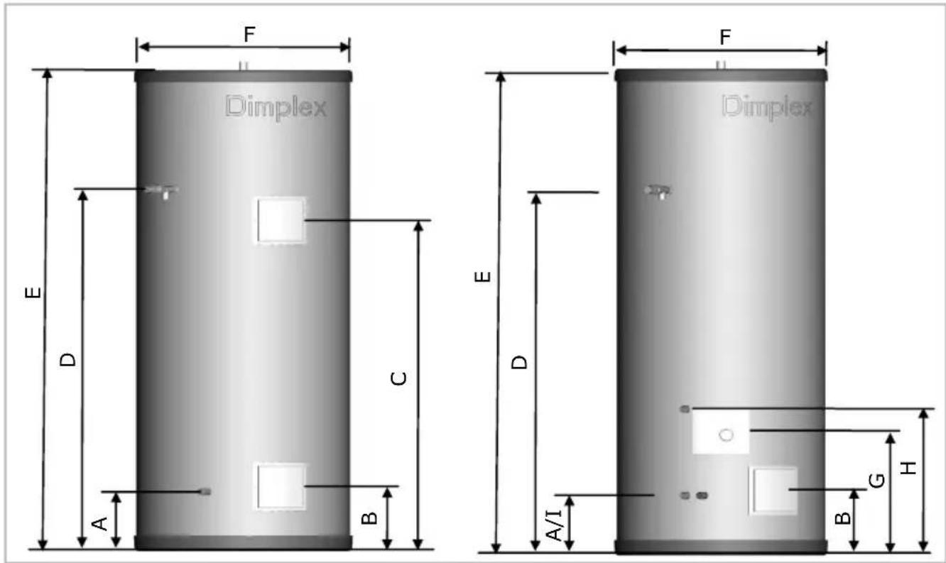
| SCxn | ||||||||
| Capacity 80 | ||||||||
| Weight [kg] | d | 27 | 30 | 32 | 37 | 43 | 50 | 59 |
| i | 29 | 32 | 35 | 40 | 48 | 55 | 65 | |
| Heat loss [kWh] | d/i | 1.12 | 1.50 | 1.82 | 2.10 | 2.59 | 2.73 | 2.88 |
| Heat up [mns] | d | 64 | 115 | 138 | 167 | 212 | 263 | 313 |
| i | 33 | 28 | 33 | 27 | 35 | 42 | 50 | |
| Re-heat [mns] | d | 53 | 90 | 104 | 124 | 153 | 184 | 220 |
| i | 23 | 21 | 24 | 24 | 30 | 35 | 42 | |
| A [mm] d/i | 182 | |||||||
| B [mm] d/i | 196 | |||||||
| C [mm] d | 570 | 648 | 753 | 821 | 1269 | 1526 | ||
| D [mm] d/i | 356 | 626 | 745 | 891 | 1116 | 1365 | 1620 | |
| E [mm] d/i | 645 | 958 | 1086 | 1243 | 1485 | 1753 | 2029 | |
| F [mm] d/i | 574 | |||||||
| G [mm] i | 339 | 380 | 369 | |||||
| H [mm] i | 445 | |||||||
| I [mm] i | 182 | |||||||
10.2 SCxn ... sd/si
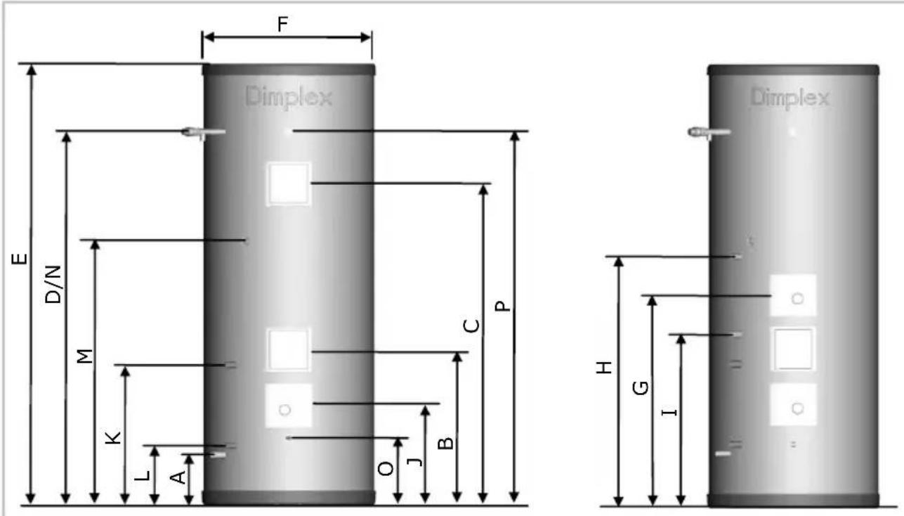
| SCxn | |||||
| Capacity 175 | 215 | 255 | 305 | ||
| Weight [kg] sd | 44 | 52 | 59 | 69 | |
| si | 48 | 56 | 63 | ||
| Heat loss [kWh] sd/si | 1.78 | 2.19 | 2.31 | 2.51 | |
| Heat up [mns] sd | 20 | 24 | 29 | 34 | |
| si | 18 | 22 | 25 | ||
| Re-heat [mns] sd | 14 | 17 | 20 | 24 | |
| si | 13 | 18 | 19 | ||
| A [mm] sd/si | 182 | ||||
| B [mm] sd/si | 531/589 | ||||
| C [mm] sd | 846 | 1087 | 1355 | 1631 | |
| D/N/P [mm] sd/si | 1017 | 1259 | 1527 | 1804 | |
| E [mm] sd/si | 1243 | 1485 | 1753 | 2029 | |
| F [mm] sd/si | 574 | ||||
| G [mm] si | 711 | ||||
| H [mm] si | 842 | ||||
| I [mm] si | 580 | ||||
| J [mm] sd/si | 346 | ||||
| K [mm] sd/si | 480 | ||||
| L/0 [mm] sd/si | 213 | ||||
| M [mm] sd | 803 | 879 | 1057 | 1196 | |
| si | 774 | 1116 | 1029 | ||
| Aux. vol. [l] sd | 90 | 130 | 170 | 220 | |
| si | 80 | 120 | 160 | ||
Dimplex UK Limited
Millbrook House Grange Drive, Hedge End, Southampton SO30 2DF
Te.: 01489 773 052, Fax.: 01489 773 061
e-mail: customer.services@dimplex.co.uk
www.dimplex.co.uk
- Unvented hot water cylinder - SCxn...d/i, SCxn...sd/si
- Overall view
- Contents
- OVERALL VIEW 2
- Before you start
- General
- Competence
- Health and Safety
- Risk assessment
- Scope of delivery
- Product features and descriptions
- Installation
- General advice
- Siting considerations
- Cold water supply and discharge pipe work
- Hot water outlet
- Immersion heater
- Indirect heating loop
- Solar loop
- Secondary return
- Installation expansion vessel
- Wiring schematic auxiliary loop
- Wiring schematic solar loop
- Solar sensor installation
- Commissioning
- SCxn ... d/i range
- SCxn ... sd/si range
- Operation
- Water temperature direct electric heating
- Water temperature auxiliary heating
- Maintenance
- Technical data
- Dimplex UK Limited
Brand : DIMPLEX
Model : SCxn305d
Category : Instant water heater and boiler