8300 - Emergency exit device Dormakaba - Free user manual and instructions
Find the device manual for free 8300 Dormakaba in PDF.


| Product Type | Rim Exit Device |
| Model | 8300 / F8300 Series |
| Manufacturer | Dormakaba |
| Compatibility | Wood or metal doors |
| Door Preparation | Flat surface, proper reinforcement required |
| Horizontal Reference Line | 40-5/16" (1024 mm) from finished floor |
| Mounting | Surface mounted on push side of door |
| Strike Options | #443, #463, #486, #319, #320 |
| Dogging | Optional cylinder dogging (clockwise to dog, counterclockwise to release) |
| Fire Rating | F8300 version for fire doors |
| Material | Metal (steel/aluminum) |
| Cutting Allowance | Touch bar and rail can be cut to length |
| Fasteners Supplied | 12-24 machine screws, #8 screws, etc. |
| Trim Compatibility | Outside lever trim or rim cylinder |
| Electronic Options | Drill 5/16" hole for electronic modules |
| Weight | Approx. 5-7 lbs (est.) |
| Power Source | None (mechanical device) |
| Maintenance | Periodic cleaning and lubrication not specified |
| Spare Parts | Contact Dormakaba for replacement parts |
Frequently Asked Questions - 8300 Dormakaba
User questions about 8300 Dormakaba
0 question about this device. Answer the ones you know or ask your own.
Ask a new question about this device
Download the instructions for your Emergency exit device in PDF format for free! Find your manual 8300 - Dormakaba and take your electronic device back in hand. On this page are published all the documents necessary for the use of your device. 8300 by Dormakaba.
USER MANUAL 8300 Dormakaba
natural_image
Technical line drawing of a mechanical assembly with two parallel supports and a cylindrical rod (no text or symbols)8300/F8300
Series Rim Exit Device
Installation instructions
95011759 (1135-30) I8300-15 - 06-2020
EN
Table of Contents
1.1 Overall 3
1.2 Door preparation 4
1.3 Prepare strike 4
1.4 Drill door for exit device 5
1.5 Verify door width 5
1.6 Install strike and chassis (fire door) 6
1.7 Install chassis, exit device and trim 6
1.8 Install covers, end cap, end cover 6
1.9 Install strike 7
1.10 OPTIONAL: Cylinder dogging
7
1.1 Overall
![8300 Series rim chassis assembly Touch bar and rail assembly 12-24 O.H.P.M.S. 12-24 R.H.P.M.S. 12-24 F.H.P.M.S. 12-24 F.H.P.M.S. 12-24 F.H.P.M.S. 12-24 F.H.P.M.S. 12-24 F.H.P.M.S. 12-24 F.H.P.M.S. 12-24 F.H.P.M.S. 12-24 F.H.P.M.S. 12-24 F.H.P.M.S. 12-24 F. H.P.M.S. 12-24 F.H.P.M.S. 12-24 F.H.P.M.S. 12-24 F.H.P.M.S. 12-24 F.H.P.M.S. 12-24 F.H.P.M.S. 12-24 F.H.P.M.S. 12-24 F.H.P.M.S. 12-24 F.H.P.M.S. 12-24 F.H. P.M.S. 12-24 F.H.P.M.S. 12-24 F.H.P.M.S. 12-24 F.H.P.M.S. 12-24 F.H.P.M.S. 12-24 F.H.P.M.S. 12-24 F.H.P.M.S. 12-24 F.H.P.M.S. 12-24 F.H.P.M.S. 12-24 F.H.P M.S. 12-24 F.H.P.M.S. 12-24 F.H.P.M.S. 12-24 F.H.P.M.S. 12-24 F.H.P.M.S. 12-24 F.H.P.M.S. 12-24 F.H.P.M.S. 12-24 F.H.P.M.S. 12-24 F.H.P.M.S. 12-24 F.H.P.M S. 12-24 F.H.P.M.S. 12-24 F.H.P.M.S. 12-24 F.H.P.M S. 12-24 F.H.P.M S. 12-24 F.H.P.M S. 12-24 F.H.P.M S. 12-24 F.H.P.M S. 12-24 F.H.P.M S. 12-24 F.H.P.M S. 12-24 F.H.P.M S. 12-24 F.H.P.M S. 12-24 F.H.P.M S . 12-38" [9] pan head phillips machine screw Dogging (omitted on F8300) Cover Edge of door stop or mullion F8300 Series rim chassis assembly End cover End cap (2) #8 x 1" PHTS Mounting plate 12-24 R.H.P.M.S (2) 8-32 x 1/4" PHTHMS "FIG. AA"](/content/2026/05/827469/images/a2629b45f837035572a42f641748a6453cb562b1e0698d6d6b8f2ffc15add962.jpg)
1.2 Door preparation
NOTE: SURFACE OF DOOR WHERE EXIT DEVICE IS TO BE INSTALLED MUST BE FLAT. PROPER REINFORCEMENT OF DOOR IS ALSO REQUIRED.
NOTE: BEFORE STARTING INSTALLATION:
- DOOR SHOULD BE FITTED AND HUNG.
- MULLION INSTALLED IF USED.
- VERIFY DOOR WIDTH WITH BOX LABEL FOR CORRECT LENGTH.
1.2.1 Measure and mark horizontal reference line on push size of door. (40-5/16" [1024] from finished floor, recommended.)
1.2.2 Measure and mark the vertical reference line (center line of chassis) on push side of door. (See dimension below.)
![40-5/16" [1024]](/content/2026/05/827469/images/a415f2b841540d48167d9406568f356c9db3d40a752814145df5db3adf8b3126.jpg)
(A.) Horizontal Reference Line
(B.)
Centerline of chassis (Verical reference line)
![Ref. dimension only Edge of door stop or mullion assis 1-9/16" [40] standard #463 & #486 strike 7/8" [22] for #443 strike](/content/2026/05/827469/images/af08404fbb8b3ea3ae95d0c3a89b81f2047493758e0e50360458271b8f3a791b.jpg)
*NOTE: ON DOORS UNDER 36" [914] ADD 1/16" [1] TO REF. DIMENSION FOR CHASSIS COVER CLEARANCE.

natural_image
Pure geometric diagram with dashed lines and a vertical line, no text or symbols present![Edge of door stop or mullion 1-9/16" [40] standard #463 & #486 strike 7/8" [22] for #443 strike Ref. dimension only](/content/2026/05/827469/images/6eb3434bc6ce14322df1c77b93a1118100a1fdfbfc381a179e4a15e17d37d2ae.jpg)
1.3 Prepare strike
For exit only device with no outside trim function
1.3.1 Remove (2) phillips head screws.
1.3.2 Then remove cam bracket assembly.
1.3.3 No additional prep required except for mounting holes. (See spotting template)
1.3.4 Proceed to step 1.4.
For device using outside trim with rim cylinder
1.3.1 Tailpiece must be trimmed 1/8" [3] to 3/16" [5] less than inside face of door.
For device using outside lever trim
1.3.1 See additional instructions packaged in trim carton

1.4 Drill door for exit device
NOTE: Vertical reference line is not centerline of cylinder
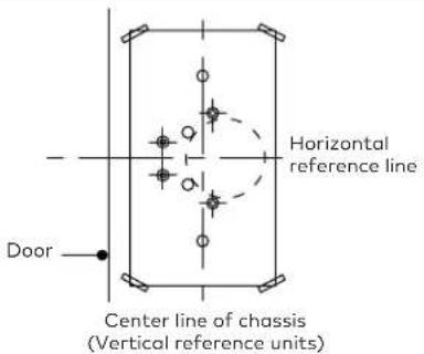
1.4.1 Refer to carton label for model and trim numbers before drilling.
1.4.2 Prepare door by using the template enclosed (tape to door).
1.4.3 Horizontal center line and center line of chassis (vertical reference) on template MUST be on horizontal and vertical reference line on door.
1.5.1 If no cutting is required; proceed to step 1.6.
1.5.2 If cutting is required, determine length by:
- measuring "A" (hinge side door stop to center of chassis), subtract 2" [51] to determine "B" (length of touch bar and rail dim.).
1.5.3 Mark length on rail (cut with touch bar depressed, packing block rotated on edge), then remove packing block and any burrs.
Centerline of chassis (vertical reference line)
!["A" 1-3/16" [30] min Hinge side of door stop End of rail 1-3/4" [44] min "B" Distance f line of tou pin to end](/content/2026/05/827469/images/f6ded03b91dc7134e7817adc798831686391c23e35bc75a446f18aaebb0bdaa2.jpg)
* Depress touch bar to cut to length
![Touch bar rail pin center ar rail ail. 1-3/4" [44] min Packing block](/content/2026/05/827469/images/1e91eb44c917b04f697c65cc8423f5e5e81d09700825fe49b05eded790503643.jpg)
1.6 Install strike and chassis (fire door)
1.6.1 When installing F8300 series device on fire doors, install strike angle (Pt. NO. 8300-015-400) per "FIG. AA", using spotting template T8300.
1.6.2 Install strike angle using (2) 12-24 F.H.P.M.S. and (2) 12-24 R.H.P.M.S. to door per drawing. 1.6.3 Install chassis using (2) 12-24 R.H.P.M.S. and (2) 12-24 F.H.P.M.S. to door per drawing.
1.7 Install chassis, exit device and trim

Install chassis to touch bar; install exit device and any trim using screws as noted on the spotting template.
1.7.1 Level touch bar/chassis assembly on door, hold mounting plate against touch bar, mark (2) holes and drill.
• No. 25 drill 1" [25] deep for wood doors.
• No. 14 drill 12-24 tap for metal doors.
• 3/8" [10] diam. drill through door for sex bolts
1.7.2 Fasten mounting plate (against rail) to door with (2) round head phillips screws. 1.7.3 For electronic options; drill additional 5/16" [8] diam. hole per detail above.
1.8 Install covers, end cap, end cover
1.8.1 Install cover(s) using (4) 8-32 x 1/4" [6] T.H.P.M.S
1.8.2 Install end cap using (2) 8-32 x 1" [25] P.H.F.H.T.S.
1.8.3 Install end cover using (2) 8-32 x 1/4" [6] T.H.P.M.S.
1.9 Install strike
NOTE: BACKSET OF DEVICE SHOWN FOR 5/8" [16] HEIGHT STOP.
![2-1/16" [53] 2-1/16" [53] 1-3/8" [35] 1-5/8" [41] No. 463 No. 486 No. 443/425 No. 319/320](/content/2026/05/827469/images/cd23542cea9615c5e812b2ae4c3ba8267f526a5c68b2f6377b8cbe1098fa64a7.jpg)
1.9.1 Install strike and adjust if necessary. Center line of strike must line up with horizontal reference line on door. Refer to carton label for strike number.
A. For strikes 486 & 443:
- Wood jamb: No. 31 drill 3/4" [19] deep
• Metal jamb: No. 21 drill-tap 10-32
B. For strikes 463, 319 or 320:
- Wood jamb: No. 25 drill 1" [25] deep
• Metal jamb: No. 14 drill-tap 12-24
1.10 OPTIONAL: Cylinder dogging
![3/64" [1] allen wrench #4-40 x 7/16" [11] set screw spacer ring (when req'd) 1" [25] min 1-1/8" [29] max Minimum/maximum lock cylinder height 5/16" to 11/32" [9] 3/4" [19] min. dormakaba cylinder supplied #90X10SC118 Touch Bar Assembly Cam Detail dormakaba #10](/content/2026/05/827469/images/d6276504b5e5c9fb39e4502d3b44faf861665c038dadafd32cc87ff1a8145c93.jpg)
1.10.1 Thread mortise cylinder into touch bar assembly (see above)
1.10.2 Snug (1) #4-40 x 7/16" set screw with allen wrench (DO NOT OVER TIGHTEN)
1.10.3 Depress touch bar and turn key clockwise to dog and counter clockwise to release.
NOTE: CYLINDER MUST BE INSTALLED WITH TOP OF CYLINDER AWAY FROM CHASSIS (See above)
- 8300/F8300
- Series Rim Exit Device
- Installation instructions
- Table of Contents
- Overall
- Door preparation
- Prepare strike
- For exit only device with no outside trim function
- For device using outside trim with rim cylinder
- For device using outside lever trim
- Drill door for exit device
- Install strike and chassis (fire door)
- Install chassis, exit device and trim
- Install covers, end cap, end cover
- Install strike
- For strikes 486 & 443:
- For strikes 463, 319 or 320:
- OPTIONAL: Cylinder dogging
Brand : Dormakaba
Model : 8300
Category : Emergency exit device