STA 7400 - Door closer Dormakaba - Free user manual and instructions
Find the device manual for free STA 7400 Dormakaba in PDF.


| Product Type | Door Closer |
| Brand | Dormakaba |
| Model | STA 7400 |
| Mounting Type | Surface-mounted |
| Application | Interior doors, light to medium duty |
| Door Width Range | Up to 1100 mm (43 in) |
| Door Weight Range | Up to 80 kg (176 lbs) |
| Size (Body) | Length: 260 mm, Height: 58 mm, Depth: 19 mm |
| Weight (Product) | Approx. 1.2 kg (2.6 lbs) |
| Power Source | Mechanical (no electricity required) |
| Closing Speed Adjustment | Yes, via hydraulic valve |
| Latching Action | Adjustable (latch speed and backcheck) |
| Backcheck | Adjustable |
| Delayed Action | Optional (model variant) |
| Hold-open Feature | Not available (standard model) |
| Operating Temperature | -20°C to +40°C (-4°F to +104°F) |
| Material | Aluminum alloy body, steel arm |
| Finish | Silver (standard), other colors optional |
| Certification | CE, EN 1154 |
| Maintenance | Check screws and oil level annually; no lubrication required |
| Cleaning | Wipe with a damp cloth; do not use solvents |
| Safety Notes | Keep fingers clear of moving parts; adjust slowly |
| Spare Parts Available | Yes (cover, arm, valves, screws) |
| Repairability | Replaceable seals and valves; serviceable by trained technician |
Frequently Asked Questions - STA 7400 Dormakaba
User questions about STA 7400 Dormakaba
0 question about this device. Answer the ones you know or ask your own.
Ask a new question about this device
Download the instructions for your Door closer in PDF format for free! Find your manual STA 7400 - Dormakaba and take your electronic device back in hand. On this page are published all the documents necessary for the use of your device. STA 7400 by Dormakaba.
USER MANUAL STA 7400 Dormakaba
STA 7414/7436 AR/ARJ/ARP
Round arm for regular, top jamb, parallel mount
Stainless steel, corrosion resistant
Installation instructions
08280730-03-2021
| EN |

Caution: sex nuts are required for attachment of components to unreinforced doors and to wood or plastic faced composite type fire doors, unless an alternative method is identified in the individual door manufacturer's listings.

When installing main arm attachment observe directions closely.

Confirm dead stop degree prior to door and frame preparations.

Make sure door efficiently operates prior to installing closer.
1 Instructions
1.1 Overall - installation types
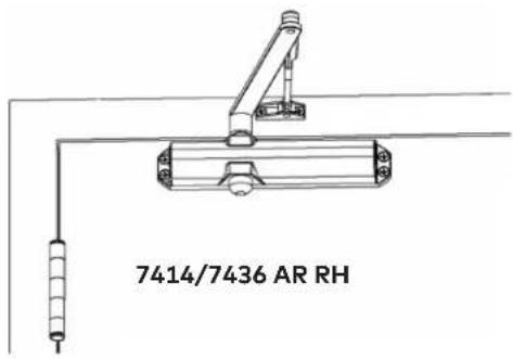
Fig.1
Right hand installation Left hand installation ATTENTION!
ATTENTION!
Before you begin, determine installation type AT, ARJ, or ARP and hand of door (RH or LH).
Also, make sure you have the tools listed below.




Tools
Tape, Tape Measure
Center Punch and Hammer
3/16" Slotted Screw Driver
3 Cross-Point Screw Driver
1/2" Box Wrench
10" Adjustable Wrench
List:
7/32, 5/32, 1/8 Drill Bits and Drill
1/4-20 Tap & Holder
5mm hex wrench
1.2 Installing arm STA 7414/7436 AR - Arm round (Regular)/mount pull side door
Fig.2

1.3 Installing arm STA 7414/7436 AR (continued)
Fig.3

Preload main arm (2) by rotating approximately 10 degrees and press rivet head into the retaining pocket on the connecting arm (4).
See template for mounting information
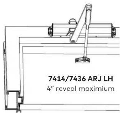
1.4 Installing arm STA 7414/7436 ARJ - Arm Round (top) Jamb/Mount Push Side of Door
Fig.4

1.5 Installing arm STA 7414/7436 ARJ (continued)
Fig.5
3B
Preload main arm (2) by rotating approximately 10 degrees and press rivet head into the retaining pocket on the connecting arm (3).


Note: shown on max. 4" reveal

natural_image
Technical line drawing of a crane lifting a beam, showing structural components without any text or symbols
Back Plate Mounting
See template for mounting information
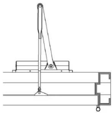
1.6 Installing 7414/7436 ARP - Arm Round Parallel/Mount Push Side of Door
Fig.6

1.7 Installing 7414/7436 ARP (continued)
Fig.7

Preload main arm (2) by rotating approximately 45 degrees.
Press main arm hub onto the closer pinion square. Secure tightly with pinion screw (7).

natural_image
Technical line drawing of a mechanical assembly with no visible text or symbols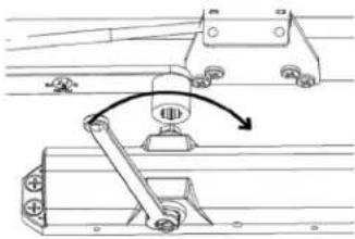
natural_image
Mechanical assembly diagram showing a lever mechanism with rotating components (no text or labels)
natural_image
Mechanical assembly diagram showing a lever mechanism with no visible text or symbols
natural_image
Technical line drawing of a mechanical assembly with no visible text or symbols
Back Plate Mounting
See template for mounting information.

Performance Adjustments:
- Be sure closer has appropriate spring power prior to making any closer speed adjustments.
- Door should close in 3 to 6 seconds from 90 degrees.
- Do not back valves out beyond closer casting surface.
- Check closing sweep (S) and latch (L) speed; adjust as necessary.
- Backcheck position will advance approximately 15 degrees by placing backcheck "position" valve in the "on" position (fully clockwise).
- Check delay action (D) function if supplied.
- Bail bearing hinges or pivots should always be used.
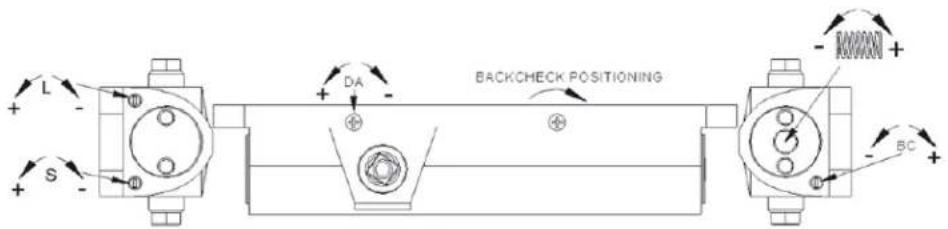
REGULAR & TOP JAMB / AR & ARJ
| Door Width | Adjuster Full Turns | Spring Size | ULC LABELED UNITS ONLY | ||
| Exterior | Interior | Max. Door Weight | |||
| 7414 | 7436 | ||||
| - | 2'-6" (762) | -9 | 2 | 100 | |
| 2'-6" (762) | 3'-0" (914) | -4 | -4 | 3 | 125 |
| 3'-0" (914) | 3'-6" (1067) | 0 | 0 | 4 | 150 |
| 3'-6" (1067) | 4'-0" (1219) | +4 | 5 | 200 | |
| 4'-0" (1219) | - | +8 | 6 | 250 | |
| ARP - PARALLEL ARM | |||||
| - | 2'-6" (762) | -4 | -4 | 3 | 100 |
| 2'-6" (762) | 3'-0" (914) | 0 | 0 | 4 | 125 |
| 3'-0" (914) | 3'-6" (1067) | +4 | 5 | 150 | |
| 3'-6" (1067) | 4'-0" (1219) | +8 | 6 | 200 | |
1.8 Cover options - COV, FCOV, FMC
Fig.8
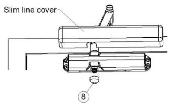


Cover screw x2

Note:
Full metal cover (FMC) attached the same manner as a full plastic cover (FCOV) without the cover insert.

- STA 7414/7436 AR/ARJ/ARP
- Instructions
- Overall - installation types
- Tools
- Cross-Point Screw Driver
- List:
- Installing arm STA 7414/7436 AR - Arm round (Regular)/mount pull side door
- Installing arm STA 7414/7436 AR (continued)
- Installing arm STA 7414/7436 ARJ - Arm Round (top) Jamb/Mount Push Side of Door
- Installing arm STA 7414/7436 ARJ (continued)
- Back Plate Mounting
- Installing 7414/7436 ARP - Arm Round Parallel/Mount Push Side of Door
- Installing 7414/7436 ARP (continued)
- Performance Adjustments:
- Cover options - COV, FCOV, FMC
Brand : Dormakaba
Model : STA 7400
Category : Door closer