
MC70LPVM - Air purifier DAIKIN - Free user manual and instructions
Find the device manual for free MC70LPVM DAIKIN in PDF.


| Product Type | Air Purifier |
| Brand | Daikin |
| Model | MC70LPVM |
| Category | Floor Standing, Wall-hanging Type |
| Power Supply | 220-240V |
| Filtration System | Pleated filter + Prefilter + Plasma Ioniser + Streamer unit + Deodorising catalyst |
| Streamer Discharge | Yes, for deodorising and decomposition of odours |
| Air Quality Sensor | Dust sensor with three-colour indicator (green, yellow, red) |
| Odour Sensor | Three-colour indicator (green, yellow, red) |
| Operating Modes | Auto fan, Manual airflow, Turbo, Anti-pollen, Sleep mode, Timer (OFF TIMER 1/2/4 hours) |
| Childproof Lock | Yes |
| Remote Control | Included with coin cell battery (CR2025) |
| Pleated Filter Replacement | Model KAC017A4E (5 pcs.), replace when filter lamp lights (approx. every 2 years) |
| Prefilter Cleaning | Every 2 weeks (vacuum or water wash) |
| UNIT1 (Plasma Ioniser) Cleaning | When UNIT1 lamp lights (soak, drain, dry) |
| UNIT2 (Streamer Unit) Cleaning | Every 3 months or when UNIT2 lamp lights (wipe or soak) |
| Safety Features | Front panel safety switch (auto stop when opened), childproof lock |
| Ozone Generation | Negligible amount, safe for health |
| Accessories Included | Pleated filter (1 sheet for initial), Operation manual, Remote controller |
Frequently Asked Questions - MC70LPVM DAIKIN
User questions about MC70LPVM DAIKIN
0 question about this device. Answer the ones you know or ask your own.
Ask a new question about this device
Download the instructions for your Air purifier in PDF format for free! Find your manual MC70LPVM - DAIKIN and take your electronic device back in hand. On this page are published all the documents necessary for the use of your device. MC70LPVM by DAIKIN.
USER MANUAL MC70LPVM DAIKIN
Floor Standing, Wall-hanging Type

natural_image
Line drawing of a white electronic device with ventilation slots and control panel (no text or symbols)MODEL
MC70LPVM
Features
About air purifying
The powerful suction of a high airflow rate captures dust, pollen, etc.
The purifying capacity improves as the airflow rate increases.

flowchart
graph TD
    A["The air permeates the room at a high airflow rate."] --> B["Pollen"]
    B --> C["Odour"]
    C --> D["Dust"]
    D --> E["Powerful suction from 3 directions"]
Effective against pollen
With the high airflow rate, even pollen that readily settles because of its large particle size is quickly caught.
Deodorising and decomposing odour in the air
The streamer discharge decomposes absorbed odour.
The decomposition cycle that maintains deodorising capability.
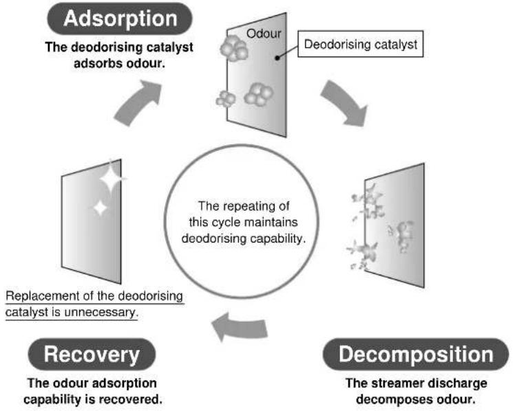
flowchart
graph TD
    A["Adsorption"] --> B["The deodorising catalyst adsorbs odour."]
    B --> C["Recovery"]
    C --> D["Replacement of the deodorising catalyst is unnecessary."]
    D --> E["The repeating of this cycle maintains deodorising capability."]
    E --> F["Decomposition"]
    F --> G["The streamer discharge decomposes odour."]
What is the "Streamer" function?

This function uses a “streamer discharge”, a type of plasma discharge, to generate high-speed electrons with strong oxidation power inside the air purifier, reducing or removing odour swiftly. (The high-speed electrons are generated and absorbed within the unit to ensure your safety.)
The hissing sound of the streamer discharge may be heard during operation. It does not indicate any operational issue. In addition, the sound may become lower or the sound quality may change according to the operating environment. These cases are also not operational issues. You may smell an odour as a particle of ozone is generated. The amount is negligible, and does not harm your health.
CONTENTS
Read before Operation
Features ....1
Safety Precautions ....3
Name and Operation of Each Part ....6
Preparation before Operation ....9
Operation
How to Operate ....13
Start / Stop, Airflow Rate, Turbo, Anti-Pollen, Sleep Mode, OFF TIMER, Display Lamp
Care and Cleaning
Quick Reference Table of Maintenance....15
Removing and Attaching Each Part .....17
Cleaning of UNIT1 and UNIT2 ....19
Replacement of the Pleated Filter ....21
Troubleshooting
Sensitivity Setting of the Air Quality Sensor (dust sensor) ...... 22
Frequently Asked Questions 23
"If these lamps light or blink"
Troubleshooting 24
Safety Precautions
Before use, read these Safety Precautions to ensure proper handling of equipment. ■
■ The precautions used in this manual are classified into the following two types. Both contain important safety information, therefore observe them at all times.
 WARNING WARNING | Improper handling may lead to serious injury or even death. | CAUTION | Improper handling may lead to injury or property damage.In some situations, the consequences may be grave. |
The icons used in this manual mean the following. ■
 | Never do. |  | Be sure to follow the instructions. |  | Disconnect the power plug. |  | Keep away from fl ames. |
 | Do not disassemble. |  | Do not handle with wet hands. |  | Do not wet. | ||
After reading this manual, keep it in a handy place for future reference by users.

WARNING
Power supply cord and plug |  | Use only a 220-240V power supply. •Other power supplies may lead to fi re or electric shock.Do not damage, remodel, bend unreasonably, pull, twist or use the •power supply cord bundled up.Also, do not place heavy objects on or pinch the power supply cord.Damage to the power supply cord may lead to fi re or electric shock.Do not use the unit when the power supply cord or the power plug is •damaged or plugged loosely into an electrical socket.A damaged or loose cord or plug may lead to fire because of a short circuit or electric shock.Do not use the unit beyond the rating of the electrical socket or •branching device.Exceeding the rating of multiple socket outlets may lead to fire because of overheating.Do not connect or disconnect the power plug to turn the unit ON / OFF. •Abusive handling may lead to electric shock or fire because of overheating. |  |
 | • Insert the power plug into the electrical socket all the way to the base.Incomplete connections may lead to electric shock or fire because of overheating.• Periodically clean the dust and other matter from the power plug with a dry cloth.Insulation failure caused by humidity or other factors may lead to fire.• Stop operation and disconnect the power plug if you detect anything strange such as burning odours.Continued use of the unit without resolving abnormalities such as burning odours may lead to electric shock or fi re because of overheating.Consult your dealer.• If the power supply cord is damaged, it must be replaced by the manufacturer, dealer or qualified persons in order to avoid a hazard.A damaged cord may lead to electric shock or fire because of overheating.• To reduce the risk of electric shock, this equipment has a polarized plug (one blade is wider than the other). This plug will fit in a polarized outlet only one way. If the plug does not fit fully in the outlet, reverse the plug. If it still does not fit, contact qualified personnel to install the proper outlet. Do not alter the plug in any way. | ||
 | • Before cleaning or relocating the unit, stop operation and disconnect the power plug from the electrical socket.Handling the unit while it is plugged in may lead to electric shock or damage. | ||
| Main unit[IMAGE] |  | • Do not use the unit anywhere there is airborne oil such as machine oil.Airborne oil may lead to cracking, electric shock or ignition.• Do not use the unit anywhere there are abundant oil vapours such as in kitchens, combustible or corrosive gases, or metallic dust.These kinds of environments may lead to fi re or damage.• Keep fingers and objects out of the air inlets, air outlet and other openings.Improper handling may lead to electric shock, injury or damage.• Do not wet the air outlet or unit frame.Contact with water may lead to fi re or electric shock. |  |

WARNING
Main unit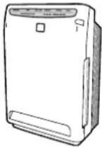 |  | Do not use combustible substances, i.e., hair spray, insecticides, etc., near the unit.Do not wipe the unit with benzene or thinner.These substances may lead to cracking, electric shock or ignition.Use a neutral detergent to clean the unit. •Use of chlorine or acidic detergents to clean the unit may generate harmful gas and harm health. |  |
 | • These servicing instructions are for use by qualified personnel only.To reduce the risk of electric shock, do not perform any servicing other than that contained in the operating instructions unless you are a professional and qualifi ed to do so. | ||
 | Keep cigarettes, incense and other naked fl ames away from the unit. •Naked flames may lead to fire. | ||
 | Do not disassemble, remodel or service the unit by yourself. •Improper handling may lead to fi re, electric shock or injury.Consult your dealer. | ||
 | Do not operate the unit with wet hands. •Contact with water may lead to electric shock. |  | |
 | Do not use the unit anywhere which is very humid such as bathrooms •or which experiences sudden temperature changes such as cold storage boxes.Improper environments may lead to electric shock or damage. |

CAUTION
Power supply cord and plug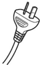 |  | Hold the power plug – not the power supply cord – and pull to • disconnect the unit.Pulling on the power supply cord may lead to fire or electric shock because of short circuits. |  |
 | Before long periods of disuse, disconnect the power plug from the • electrical socket.Degraded insulation may lead to electric shock, current leaks or fire. | ||
| Main unit |  | Do not use the unit anywhere it is exposed to direct sunlight, rain or • wind.Overheating or contact with water may lead to fi re or electric shock.Do not use the unit anywhere which is hot such as near heaters.High temperature may discolour or deform the unit.Do not block the air inlets or air outlet with laundry, cloth, curtains, etc.Adhered lint may obstruct the air passage, possibly leading to overheating and fire.Do not use the unit on an uneven floor.If the unit topples over, water may spill from it, possibly wetting furniture or leading to fire or electric shock.If the unit topples over, put it upright immediately.Do not use the unit anywhere chemicals are handled.Volatile chemicals or solvents (found in hospitals, factories, test labs, beauty salons, photo developing labs, etc.) may degrade mechanical parts, possibly causing water leaks which may wet furniture, etc.Do not use powders such as cosmetics near the unit.Contact with powders may lead to electric shock or damage.Do not use the unit in cramped spaces such as closets.Poor ventilation may lead to overheating and fi re. |

CAUTION
Main unit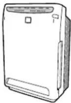 |  | Do not expose plants or animals to direct air currents from the unit. •Overexposure to air currents may have adverse effects.Keep fish tanks, vases and other water containers away from the unit.Water infiltration into the unit may lead to electric shock, fire or damage.Do not climb, sit or lean on the unit. •Falling or toppling over may lead to injury.Do not remove the fi Iter with the unit lying on its side. •Handling of this sort facilitates dust infiltration, possibly leading to fire or electric shock.Do not use the unit close to lighting equipment (within 1m). •The response of the main unit to the signal from the remote controller may be weakened and the colour of the unit may change.Do not use the unit near to a fire alarm.If the air from the outlet is blown toward a fire alarm, the alarm may respond late or it may not respond. |  |
 | Regularly ventilate the room when using the unit in conjunction with •combustion appliances.Inadequate ventilation may lead to carbon monoxide poisoning.This product does not remove carbon monoxide.This product is not intended to be used by persons with reduced •physical, sensory or mental capabilities, or with a lack of operation knowledge, unless they are given supervision or instruction concerning appliance use by the person responsible for their safety.Keep the appliance out of children's reach to ensure that they do not play with it.Unplug the unit during cleaning.•Handling the unit while it is plugged in may lead to electric shock or damage.This equipment should be inspected frequently and collected dirt •removed from it regularly to prevent excessive accumulation which may result in flashover or a risk of fire. | ||
| Other |  | If you use the unit where pets are kept, be careful that pets do not •urinate on the unit or bite the power supply cord.This may lead to electric shock or fire. In the event of abuse by pets, stop operation, disconnect the power plug and consult your dealer.Do not use combustion appliances where they are directly exposed to air currents from the air outlet.Incomplete combustion by the combustion appliance may lead to carbon monoxide poisoning, etc.As using indoor fumigating insecticides, stop operation to prevent chemicals from being sucked into the unit.Because chemicals accumulate inside the unit, some persons may, depending on their physical condition, be hypersensitive and have their health jeopardized as a result. |  |
Precautions during use
- Keep TVs, radios, stereos, radio clocks and antenna wires at least 2m away from the unit.
The effects of the power circuit inside the unit and cable may cause a distorted TV picture or noise.
(However, audio interference may occur even beyond 2m depending on the strength of the electric waves. Reception is particularly hindered when using indoor antennas, therefore distance antennas far enough away to prevent noise from being picked up.) - Do not use the unit in the place of kitchen fans or stove hoods.
This kind of use may shorten the service life of the prefilter and the pleated filter, possibly leading to damage. - Do not use the unit to preserve artwork, academic materials, etc., or for commercial or other special applications.
This kind of use may place the quality of preserved objects. - Correctly attach parts after cleaning the unit.
Using the unit with parts such as fi Iters removed may lead to damage.
Streamer discharge and electric dust collection
- Odour may escape from the air outlet due to the slight amount of ozone generated, but the amount is negligible and human health is not affected.
Name and Operation of Each Part
Front
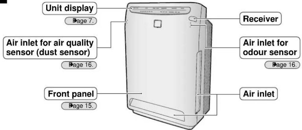
Rear


Name and Operation of Each Part
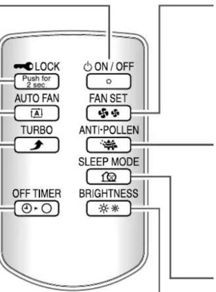
Remote controller
Page 13, 14.

flowchart
graph TD
    A["Child proof lock button"] --> B["ON / OFF button"]
    A --> C["Fan setting button"]
    A --> D["Anti-pollen button"]
    A --> E["Sleep mode button"]
    A --> F["Brightness adjustment button"]
    G["Auto fan button"] --> H["LOCK Push for 2 sec"]
    I["Turbo button"] --> J["AUTO FAN"]
    K["OFF TIMER button"] --> L["TURBO"]
    M["ON / OFF"] --> N["FAN SET"]
    O["ON / OFF"] --> P["ANTI-POLLEN"]
    Q["ON / OFF"] --> R["SLEEP MODE"]
    S["ON / OFF"] --> T["BRIGHTNESS"]
    U["OFF TIMER"] --> V["OFF TIMER"]
    W["ON / OFF"] --> X["ON / OFF"]
    Y["ON / OFF"] --> Z["ON / OFF"]
    style A fill:#f9f,stroke:#333
    style G fill:#ccf,stroke:#333
    style K fill:#cfc,stroke:#333
    style M fill:#fcc,stroke:#333
    style U fill:#cff,stroke:#333
    style W fill:#ffc,stroke:#333
Unit display
Child proof lock lamp (orange)
natural_image
Diagram of a device panel with buttons and a central display (no text or symbols)Airflow rate lamp (green)
An airflow rate lamp indicates the airflow rate during “A (Auto fan)” and “airfl ow manual” operation.
Air quality sensor lamp (dust sensor)
The three-colour indicators (green, yellow, red) indicate how unclean the air is.
When the air is clean, the green lamp lights up.
In the following case, only the green lamp lights up for the initial ■ 7 seconds regardless of the uncleanness level.
1) Operation directly after attaching the front panel and UNIT1
2) Operation directly after reconnecting the power plug
When the sensitivity of the air quality sensor is poor, change the setting.
Page 22.
The sensitivity of the air quality sensor may fall depending on the installation site or the size of particles.
If this bothers you, change the installation site of the unit (Page 11.) or adjust the sensitivity of the air quality sensor. (Page 22.)

| Detectable Cigarette smoke, pollen, ticks, house dust, animal hair, diesel soot |
| Sometimes detectable Steam, oil vapours |
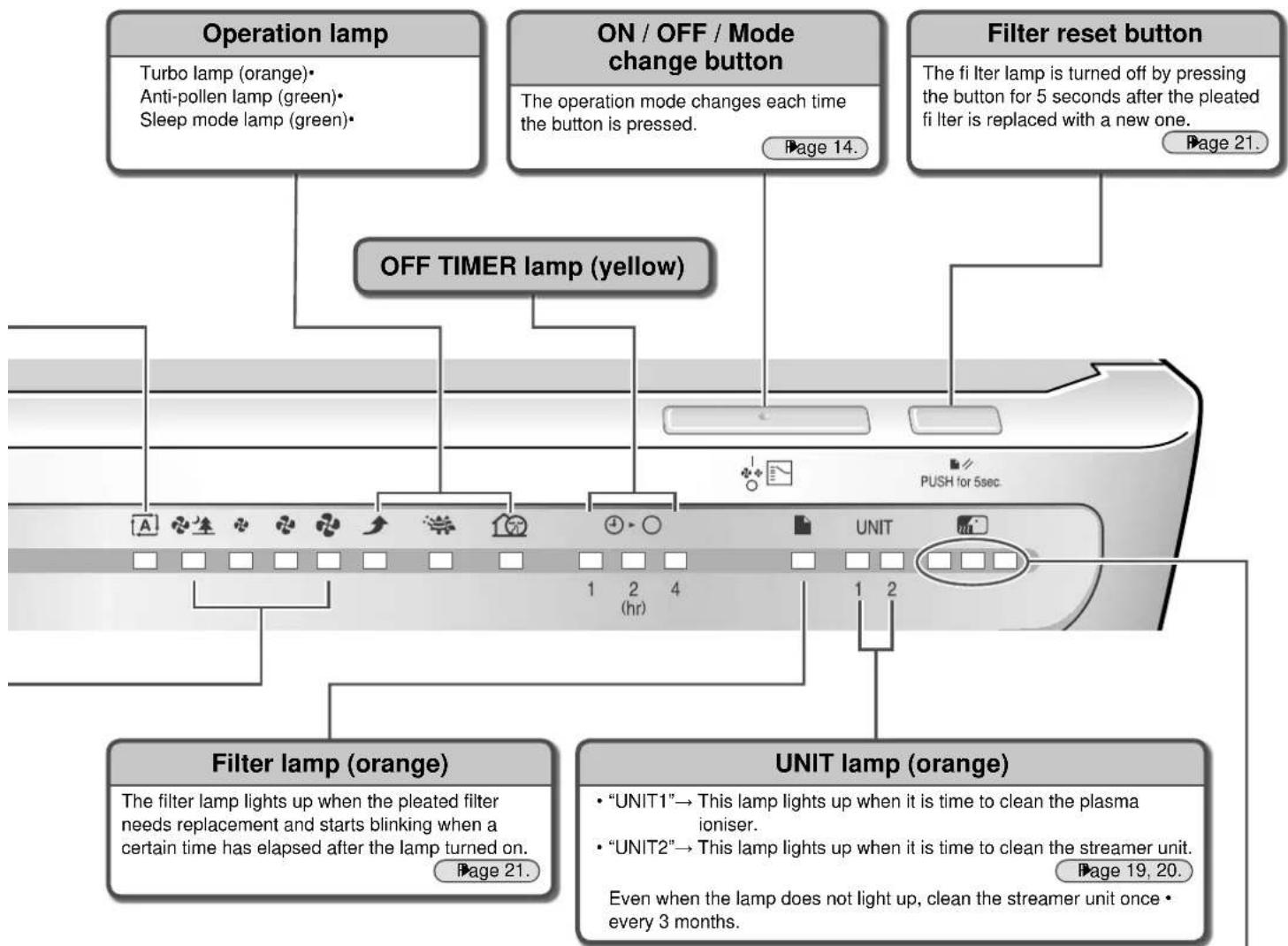
Odour sensor lamp
The three-colour indicators (green, yellow, red) indicate the odour level.
When the air is clean, the green lamp lights up.
In the following case, only the green lamp lights up for the initial ■ 1 minute. The initial level of odour is recorded as the standard level.
1) Operation directly after attaching the front panel and UNIT1
2) Operation directly after reconnecting the power plug
If the odour level remains constant without intensifying or weakening, the odour sensor may not detect even strong odours.
The odour sensor may not detect certain types of odours such as pet odours other than ammonia, garlic, etc.
Even if only the green lamp lights up, you may notice some smell because the sensitivity is different among individuals.
If bothered by odours, set airflow manual operation and run the unit at a higher airflow rate.

| Detectable | Cigarette odours, cooking odours, pet and toilet odours, raw waste odours, mildew odours, sprays, alcohol |
| Sometimes detectable | Sudden changes in temperature and humidity, odourless gases such as carbon monoxide, steam, oil vapours, gas from combustion appliances |
Preparation before Operation
Accessories check ■
Confir rm all the accessories are included.
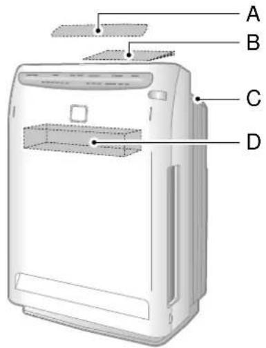
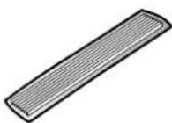
A: Pleated filter...1 sheet < For initial installation > Inside cushion

B: Operation manual...1 book (This booklet) Inside package

C: Remote controller...1 unit In remote controller storage slot
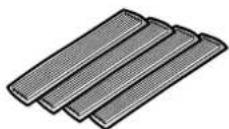
D: Pleated fi Iters...4 sheets < Replacement fi Iters > In fi Iter container
How to attach the pleated ■ fi Iter
Make sure to attach the pleated filter before starting operation.
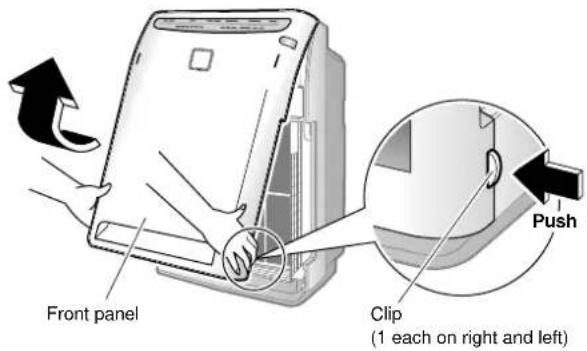
Remove the front panel. 1
Push the 2 clips (right and left), and pull the front panel • upward and remove it.
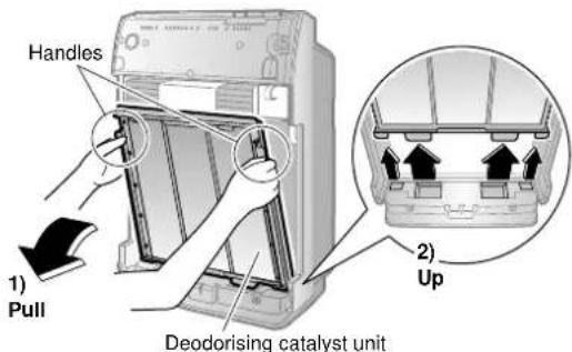
Remove UNIT1.2
Holding UNIT1 by the handles, pull UNIT1 upward and remove it.

Remove the deodorising catalyst unit.3
Holding the deodorising catalyst unit by the handles, pull the deodorising catalyst unit upward and remove it.
Attach the pleated fi Iter. 4
Make sure to set the prefilter (green) and the pleated filter (front: white, rear: blue) in place.
If you operate the unit without them, the unit may be damaged.
Fit the holes (5 each on the right and left) of the pleated 1) filter to the fixing lugs (5 each on the right and left) of the deodorising catalyst unit.

Insert the pleated fi Iter underneath the tabs (4 locations) 2) at the top and bottom of the deodorising catalyst unit.
Top and bottom tabs (4 locations)

Unit performance drops if the pleated fi Iter is attached • backward.
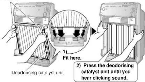
Attach the deodorising catalyst unit. 5
- Holding the deodorising catalyst unit by the handles, fit the projections into the grooves (4 locations) at the bottom of the main unit and press the deodorising catalyst unit into the main unit.
Handles
Attach UNIT1.6
Holding UNIT1 by the handles, fit the projections into the • grooves (2 locations) at the bottom of the main unit, and press UNIT1 into the main unit.

Attach the front panel. 7
Fasten the top hooks (2 locations) of the front panel to the • top grooves (2 locations) of the main unit and then close the front panel.
![Top grooves (2 locations) 1) Fasten the hooks. Front panel [View from above] Top hooks (2 locations) 2) Press the front panel until you hear clicking sound.](/content/2026/05/826977/images/2318fbe6f28c381654bd9b664a5199578f0b974f5ae2479d887da8cfc5f8cb64.jpg)
If the front panel is improperly set, the safety switch may be activated. Operation may not start. Page 16.
Preparation before Operation
Installation of the unit ■
Installed on a table or the floor
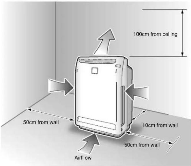
CAUTION
- The wall where the air purifier is set may get dirty depending on the type of wall and environment, even if you follow the specified dimensions of left. In such cases, move the unit a safe distance away from the wall. If the air purifier is used for a long time at the same location, the bottom of the unit and floor may become dirty due to the suction air flow from the bottom of the unit. Periodic cleaning is recommended.
ATTENTION
The air is blown slightly to the right, but nothing is wrong with the unit.
Select a location which allows the air to reach the entire room.
- Place the air purifier on a flat area where it is stable. If the floor is uneven, the unit may vibrate excessively.
Hints for smart installation
To remove house dust, it is effective to install the unit at a lower position in the room. To remove cigarette smoke, it is effective to install the unit in a higher part of the room.
- If you install the air purifier opposite the air conditioner, the circulation effect is enhanced. The unit controls unevenness in the room temperature while cleaning the air during heating or cooling operation.
Keep TVs, radios and stereos 2m or more away from the unit.
(The effects of the power circuit inside the unit and cable may cause a distorted TV picture or noise.)
Keep cordless phones or atomic radio clocks away from this unit also.

flowchart
graph TD
    A["Airflow"] --> B["Window"]
    B --> C["Phone"]
    C --> D["Printer"]
    D --> E["Airflow"]
    E --> F["Phone"]
    F --> G["Printer"]
    G --> H["Airflow"]
    H --> I["Phone"]
Do not use the unit in the following places.
Do not use the unit in a location exposed to direct sunlight.
(The response of the main unit to the signal from the remote controller may be weakened and the colour may change.)
- Do not use the unit in locations of high temperature. (Heat may discolour and deform the unit.)
- Exposed to soot (conductive dust) generated by candles, aromatic candles, etc. The operating efficiency of the filter may be lowered, and the room may become dirty due to dust that is not collected.
- Near to a fire alarm If the air from the outlet is blown toward a fire alarm, the alarm may respond late or it may not respond.
- Do not use cosmetics, etc. combined with silicone near the unit. *Cosmetics, antiperspirant, antistatic agent, waterproof spray, spray polish, glass cleaner, chemical wiping cloths, wax, and hair care products (split ends coating agent, hair mousse, and hair conditioner). Insulators such as silicone may adhere to the needle of the streamer unit, and a streamer may not be generated. In this case, clean UNIT2. ▶Page 20.
Preparation of remote controller
A battery is already set in the remote controller.
The remote controller can be used only after pulling out the clear sheet.

Battery replacement
1 Move the tab of the cover on the rear of the remote controller in the direction of the arrow.
2 Pull out the cover.
Replace the battery.3
Close the cover to its original position.4
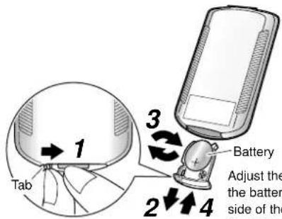
Adjust the + side of the battery to the ⊕
side of the cover and insert the cover.
Insert the power plug into an electrical socket.
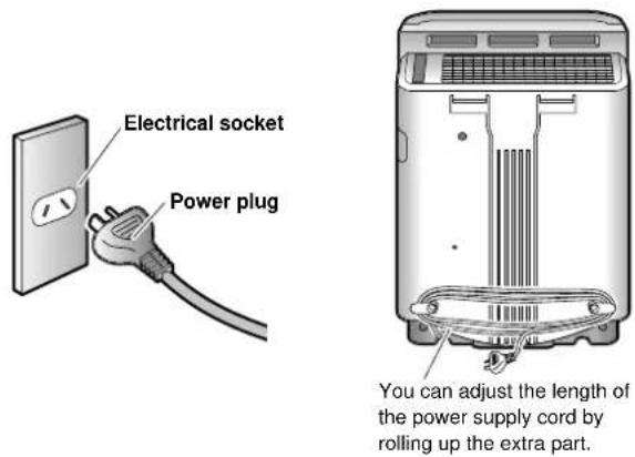
How to use
Point the transmitter of the remote controller toward the receiver of the unit.
If there is an obstruction to the signal, such as a curtain, the unit may not receive the signal.
The distance from which the remote controller can transmit is about 6m.
![Transmitter [View from above] Receiver 5m 30° 30° 5m 6m Detection area](/content/2026/05/826977/images/0c715cfc7a764db949d673dff5baddacc65fc7d41c7fddc0f54180491eaf4d6d.jpg)
NOTE
Battery

Store the batteries where babies and children can not reach them.
If, by chance, a battery is swallowed, make sure to contact a doctor immediately.
When discarding batteries, cover the terminals of the batteries with tape.
If mixed with other metal or batteries, heat, explosion or combustion may occur.
• The replacement target is about 1 year but if reception becomes difficult, replace the battery with a new coin type CR2025 (lithium) battery.
- It may be necessary to replace a coin type battery which is approaching its expiration date before the recommended date.
- In order to prevent malfunctions or injuries due to leaking or explosions, make sure to remove the coin type battery when the unit will not be used for a long period of time.
- The coin type battery which comes with the remote controller is for the initial operation. The coin type battery may run down in less than 1 year.
Remote controller

- Be careful not to drop or get the remote controller wet. (It causes malfunction.)
- The signals may not be received very well because of electronic lighting style fluorescent lamps (such as inverter fluorescent lamps) in the same room.
- Do not use the remote controller close to the lighting equipment (within 1m).
(The sensitivity of the main unit to the signal from the remote controller may be weakened and the colour of the unit may change.)
How to Operate

To start the operation

Operation starts and the airflow rate lamp lights up.
When you press ON/OFF during operation, operation stops.
When you press ON/OFF next time, operation starts with the same settings as the previous operation.
(Example of the initial display)
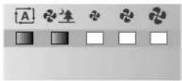
To prevent mishandling by small children
Childproof lock
Press • LOCK for about 2 seconds to engage the childproof lock.
You can release the childproof lock by pressing ☐ Lock • Push for 2 sec. again for about 2 seconds.
You can also release the childproof lock when you disconnect the power plug once, and after 3 seconds or more, reconnect the power plug.
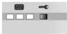
To operate the unit according to the cleanness level of the air
Auto fan operation

The auto fan lamp and one of the airflow rate lamps •
" (Quiet)", " (Low)", " (Standard)", or " (High) light up.

To clean the air in the room quickly
Turbo operation


To set the timer
Timer operation

Each time the button is pressed, the OFF TIMER is set as follows.
→ "1" (1 hour) → "2" (2 hour) → "4" (4 hour) → (Cancel)


natural_image
Line drawing of a white electronic device with a door and ventilation slots (no text or symbols)Make sure that the front panel is closed.

Operation with the button on the unit
Press

- The operation mode changes each time the button is pressed.

flowchart
graph TD
    A["Stop"] --> B["(Sleep mode)"]
    B --> C["Anti-pollen"]
    C --> D["Turbo"]
    D --> E["High"]
    A --> F["(Auto fan)"]
    F --> G["Quiet"]
    G --> H["Low"]
    H --> I["Standard"]
    I --> J["High"]
To change the airflow manually
Airflow manual operation

Each time the button is pressed, the airflow rate changes as follows.

To clean pollen
Anti-pollen operation


To operate quietly when you are sleeping
Sleep mode operation

The sleep mode operation lamp and one of the airflow rate lamps “(Quiet)” or “(Low)” light up.
To change the brightness of the unit display lamp
BRIGHTNESS
Press
- The brightness of the unit display lamp changes each time the button is pressed.
- It is only the air quality sensor lamp and the odour sensor lamp which completely go off.
< Air quality sensor lamp / Odour sensor lamp >

< Other display lamp >

NOTE
- Do not start or stop operation by disconnecting or reconnecting the power plug except in the case of malfunction.
- Do not move the unit during operation. It may cause operational issues or malfunction.
ATTENTION
• Operation stops for safety when the front panel is opened during operation.
■When any malfunction occurs during operation
- If the unit display is abnormally lit or the signal from the remote controller can not be received during operation due to electric lighting or radio interference, disconnect the power plug once. After 3 seconds or more, reconnect the power plug and start operation.
■Start / Stop
- The default setting for the airflow rate is "A (Auto fan)" airfl ow. When you disconnect the power plug or remove the front panel, the setting for the airfl ow rate returns to "Auto fan".
- Before cleaning, make sure to stop operation and disconnect the power plug.
■Auto fan operation
- The airflow rate is automatically selected from “(Quiet)”, “(Low)”, “(Standard)”, or “(High)” according to the uncleanness level of the air.
- The purifying capacity improves as the airflow rate increases.
■Turbo operation
- A high airflow rate quickly removes any contaminants in the air. This is convenient to use when cleaning the room.
■Quiet operation
- A gentle flow of air is discharged. Use this operation especially while sleeping. During the quiet operation, the deodorising performance decreases. If the room is not deodorised well, please use the "Standard" or stronger operation mode.
■Anti-pollen operation
- The airflow rate switches over between "Standard" and "low" every 5 minutes and produces a moderate air stream to catch the pollen before it drops on the floor.
■Sleep mode operation
- The airflow rate is automatically selected from “(Quiet)” or “(Low)” according to the cleanliness level of the air. - This is convenient to use when sleeping.
■Timer operation
- The remaining time is indicated by the OFF TIMER lamp. - The set time can also be changed when the button is pressed while the timer is counting.
■Childproof lock
- While the lock is engaged, the operation of the unit and the remote controller are limited to prevent small children from mishandling them.
Quick Reference Table of Maintenance

WARNING
Before performing maintenance, stop the unit and disconnect the power plug. (It may cause electric shock or injury.)
Remove the parts for maintenance in numerical order.
For details on removing and attaching each part, see Page 17.
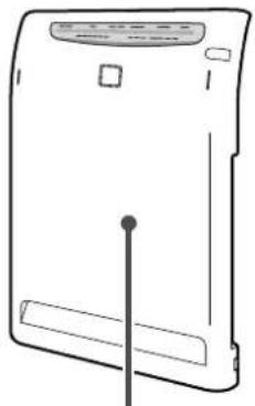
natural_image
Line drawing of a rectangular electronic device with a central pin and top panel (no text or symbols)
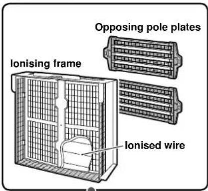

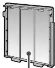
| 1 Front panel | 2 Prefi Iter | 3 UNIT1(Plasma ioniser) | 4 UNIT2(Streamer unit) |
 |  |  (The fi gure above showsUNIT1 after the opposingpole plates are removed.) (The fi gure above showsUNIT1 after the opposingpole plates are removed.) |  |
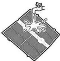
| If it gets dirtyWipe | About once every 2 weeksVacuum cleanerRinse with water | If the “UNIT1”lamp lightsSoak, drain and dryWipe | Once every 3 months or ifthe “UNIT2” lamp lightsSoak, drain and dryWipe |
| Wipe off the dirt with a cloth •slightly moistened with water.In the case of heavy dirt, wipe it •off with a cloth moistened withneutral detergent.Do not use hard brushes, etc.• | Use a vacuum cleaner to •remove the dust from theprefi Iter, and wash it with water.In the case of heavy dirt, wash •the prefi Iter with a soft brush orneutral detergent and dry it wellin the shade.Dry the prefi Iter completely beforeusing it because the “UNIT1” lampmay light up if any water dropsremain on the prefi Iter. | Use a vacuum cleaner to remove the dust.•Soak in lukewarm water or water. (About 1 hour)•Dry thoroughly after soaking.•Care and Cleaning Page 19, 20. | |

WARNING
- Do not use gasoline, benzene, thinner, scouring powder, kerosene, alcohol, etc.
(Cracking, electric shock or fire may occur.) - Do not wash the main unit with water. (Electric shock, fi re or malfunction may occur.)
NOTE
When detergent is used, wipe the detergent off the surface to prevent any residue.
Do not dry the prefi iter in a place exposed to direct sunlight.
Do not use hot water with a temperature of 50^ C or higher for • cleaning the parts.
Do not dry the parts over a fire.
It may cause discolouration or deformation of the parts and the parts may become unusable.

natural_image
Technical line drawing of a rectangular frame with internal compartments and a central post (no text or symbols)
natural_image
Technical line drawing of a portable electronic device with ventilation grilles and control panel (no text or symbols)| 5 Pleated fi Iter | 6 Deodorising catalyst unit | 7 Main unit or air inlet for sensor |
| Pleated fi IterDeodorising catalyst unitFace the white side to the front. | Do not rinse with water.Do not rub the front surface. | Air inlet for odour sensorAir inlet for air quality sensor |
| If the fi Iter lamp lights up or blinksReplace | About once a month, or if the odour or marking is a concernVacuum cleanerCan not be rinsed in water | If it is cloggedVacuum cleanerWipe |
| Replacement Page 21. | Use a vacuum cleaner to remove the dust.• If the deodorising catalyst unit frame • becomes dirty, wipe off the dirt with a cloth slightly moistened with water. In the case of heavy dirt, wipe it off with a cloth moistened with neutral detergent.Do not wash with water. (If the unit is • washed with water, it will be deformed and become unusable.) | If the main unit or the air inlet for the air • quality / odour sensor is clogged with dust, use a vacuum cleaner to remove the dust.For the main unit, wipe off the dirt with a • cloth slightly moistened with water. |
NOTE
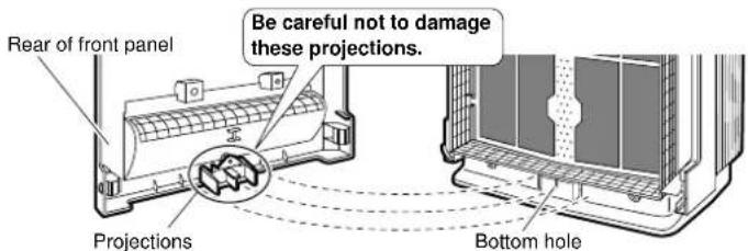
- Be careful not to scratch the surface of the front panel or damage the projections on the rear of it after it is removed.
The projections on the rear work as a safety switch that shuts power off when the front panel is opened. If they are damaged, operation can not start.

WARNING
Do not touch the inside of the hole at the bottom of the unit. (Electric shock may occur.)
Consult your dealer if the unit is damaged and does not operate.
Removing and Attaching Each Part
Remove
Remove the front panel. 1
Push the 2 clips (right and left), and pull the front panel • upward and remove it.

Remove the prefi Iter.2
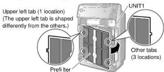
Hold the indent and pull the prefi iter. Then, unhook the • tabs (4 locations) of the prefi iter from the holes (2 each on the right and left) of UNIT1.

Note
Use a vacuum cleaner to remove the dust before removing the prefi lter.

Remove UNIT1.3
Holding UNIT1 by the handles, pull UNIT1 upward and remove it.

Remove the deodorising catalyst unit.4
Holding the deodorising catalyst unit by the handles, pull the deodorising catalyst unit upward and remove it.

Attach
Attach the deodorising catalyst unit. 1
- Holding the deodorising catalyst unit by the handles, fit the projections into the grooves (4 locations) at the bottom of the main unit and, press the deodorising catalyst unit into the main unit.

Attach UNIT1.2
Holding UNIT1 by the handles, fit the projections into the • grooves (2 locations) at the bottom of the main unit, and press UNIT1 into the main unit.

3 Attach the prefilter.
- Fit the tabs (4 locations) of the prefilter into the holes (2 each on the right and left) of UNIT1.
4 Attach the front panel.
- Fasten the top hooks (2 locations) of the front panel to the top grooves (2 locations) of the main unit and then close the front panel.
![Top hooks (2 locations) Top grooves (2 locations) 1) Fasten the hooks. Front panel [View from above] 2) Press the front panel until you hear clicking sound.](/content/2026/05/826977/images/5b84f1afdd09667c99e64012cb9568d1a567a36fcc27aca2b6495a925ec97cc1.jpg)
If the front panel is improperly set, the safety switch may be activated. Operation may not start. ▶Page 16.
Removing and attaching the opposing pole plates ■

CAUTION
Wear rubber gloves to remove and attach the opposing pole plates. Hands can be cut on the opposing pole plates and ionised wires.

Remove
Remove the front panel and UNIT1. 1 Page 17.
Remove the opposing pole plates from 2 the rear of UNIT1.
Pinching together the white and green knobs (2 sets on the right and left), lift the opposing pole plate up and remove it.

Attach
Attach the opposing pole plates. 1
Fit the opposing pole plate over the knobs (2 sets on the 1) right and left) on the ionising frame.
The opposing pole plates have no difference between the upper and the lower, or between the right and the left. Attach them so that the arrow is visible.

Insert securely until it clicks.2)

natural_image
Illustration of a hand inserting a grid into a rack inside a plastic tray (no text or symbols)Attach the other opposing pole plate.3)

natural_image
3D diagram of a heat exchanger or cooling unit with internal grid structure and directional arrows (no text or symbols)Attach UNIT1 and the front panel.2
Cleaning of UNIT1 and UNIT2
| Time for cleaning | UNIT1:If the “UNIT1” lamp lightsUNIT2:Once every 3 months or if the “UNIT2” lamp lights |  |
| Cleaning method | Soak, drain and dry Wipe |
If marking is a concern, clean the unit even if the "UNIT1" and "UNIT2" lamps do not light.
For details on removing and attaching each part, see Page 17.
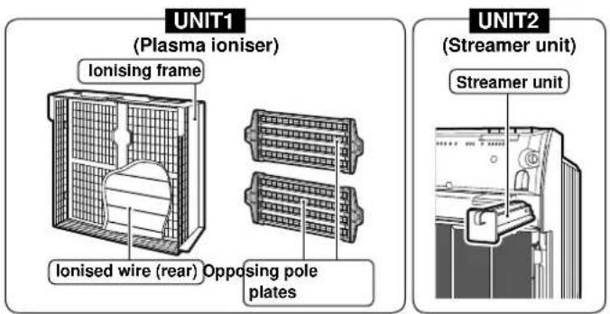
| Procedure | UNIT1Ionising frame / Ionised wire Opposing pole plates | |
| Remove the parts. | Page 9. Page 17, 18. | Page 18. |
| Use a vacuum cleaner to remove the dust. | ||
| Soak in lukewarm water or water.(About 1 hour) | ||
| Remove dirt with a piece of cloth, soft brush, etc.Wear rubber gloves. | Wear rubber gloves.Cloth Cotton swab Wipe For details,1) Ionising frame2) Ionised wire | Wear rubber gloves.Cloth Brush Rub |
| Rinse in running water and drain. | ||
| Dry in a well-ventilated, shaded place. (About 1 day) | ||
| Attach the parts. | Page 10. Page 17, 18. | Page 18. |
1) Ionising frame
(Remove dirt after soaking but before drying.)
Remove dirt from plastic • parts with a soft piece of cloth.
Use a cotton swab, etc. to • wipe away dirt in recesses and places where fingers do not fit.
Do not leave any lint from • cleaning cloths behind. Lint may lead to malfunctions.

2) Ionised wire (8 locations)
Remove dirt from the ionised wires and surrounding plastic parts with a soft piece of cloth.
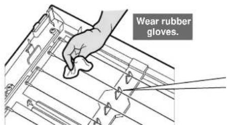
* Wipe the ionised wires gently. Pulling on them forcefully may cause them to snap.

CAUTION
Wear rubber gloves when wiping or rubbing the units. ■
Hands can be cut on the opposing pole plates, ionised wires and needles of streamer unit.
■ There are ionised wires on the rear of the opposing pole plates. Be careful not to snap these wires when removing and attaching the units.
- If the unit is operated with broken ionised wires, the "UNIT1" lamp lights. While the lamp is lit, dust collecting capacity is low.
- If any ionised wire is accidentally cut, it is necessary to replace the ionised wire with a new one. Consult your dealer.
(Do not replace the ionised wire by yourself.)
ATTENTION
- Operation can be performed safely without the streamer unit installed on the main unit, but this degrades the deodorising performance. Use the main unit after the streamer unit is installed.
| UNIT2 | Notes | |
| Streamer unit | ||
| Open the front panel and pull out the streamer unit. | ||
| Do not remove the screws from the ionising frame or UNIT2.•This may lead to damage. | ||
 | Clean UNIT1 and UNIT2 somewhere which can be wet such as in a shower room or •kitchen sink.For stubborn dirt, soak UNIT1 and UNIT2 in lukewarm water or water in which neutral •liquid detergent (i.e., kitchen cleaner, etc.) has been dissolved.Use the amount of neutral liquid detergent indicated in the instructions for the detergent.•Do not use powdered, alkaline or acidic cleaner, and do not rub with hard brushes, etc. •Doing so may cause deformation, damage, or rust.• If the needles inside UNIT2 are deformed, deodorising capacity diminishes. | |
  Wear rubber gloves.WipeFor details,3) Streamer unit Wear rubber gloves.WipeFor details,3) Streamer unit | ||
  | • If detergent remains on UNIT1 or UNIT2, the “UNIT1” and “UNIT2” lamps do not go off after cleaning, therefore rinse off the detergent well.• Do not leave any lint from cleaning cloths behind. Lint may lead to malfunctions. | |
| • Plastic parts may deform or discolour if exposed to direct sunlight.• If water remains on UNIT1 or UNIT2, even in small quantities, the “UNIT1” and “UNIT2” lamps do not go off after cleaning, therefore dry them throughly in the shade. | ||
| Reattach the streamer unit as before. | ||

Clean the ionised wires without dislodging them from the V-groove.
3) Streamer unit
Wipe the needles lightly with a soft piece of cloth such as a cotton swab moistened with water or neutral liquid detergent if dust is adhered to them.
Remove dirt from plastic •
parts ( ) and metal parts
in internal areas with a cotton
swab or a soft piece of cloth.
Do not remove the screws.

* If the needles are deformed, deodorising capacity diminishes.
Replacement of the Pleated Filter
| Time for cleaning | When the fi Iter lamp in the display lights up or blinksIt is not necessary to replace the pleated fi Iter until the fi Iter lamp lights up or blinks. |  |
| Cleaning method | Replace | |

Remove the front panel and UNIT1. 1 Page 17.
Replace the pleated fi Iter with a new 2 fi Iter.
Remove the used pleated fi iter.1)
Release the pleated fi Iter from the projections • (5 each on the right and left) of the deodorising catalyst unit (front side).
2) Take out a new pleated filter from the filter container and then attach it to the deodorising catalyst unit.
Fit the holes (5 each on the right and left) of the • pleated fi iter onto the tabs on the right and left of the deodorising catalyst unit.
- Insert the pleated filter underneath the tabs (4 locations at the top and bottom) of the deodorising catalyst unit.

3 Attach UNIT1 and the front panel.
Page 17.
4 Connect the power plug.
5 Press the filter reset button on the upper part of the front panel for 5 seconds.
(The filter lamp goes off with a short beep sound.)

- Even if the pleated filter is replaced, the filter lamp does not go off unless you press the filter reset button for 5 seconds.
NOTE
- Order the pleated filter for replacement from your dealer.
- Replace the pleated filter when the filter lamp lights up or blinks even if the filter looks clean. The amount of visible dirt does not represent the capacity of the filter.
- The replacement interval for the pleated filter varies according to how the unit is used and where it is located.
The filter lamp lights up after about 2 years if the unit is used every day in a house where 10 cigarettes per day are smoked. (The replacement interval shortens when the unit is used where the air is particularly dirty.) - When you have replaced the pleated filter before the filter lamp lights up because of visible dirt or generation of odour, press the filter reset button for 5 seconds.
Options
ATTENTION
- For replacement pleated filters contact the service shop.
| Part | Model |
| Pleated filter 5 pcs. | KAC017A4E |
• If the unit is used with dirty parts
• Air is not cleaned.
- Odors are not removed.
- Unnecessary odors may be generated.
- Discard of the pleated filters as noncombustible waste.
Sensitivity Setting of the Air Quality Sensor (dust sensor)
The sensitivity of the air quality sensor can be changed.
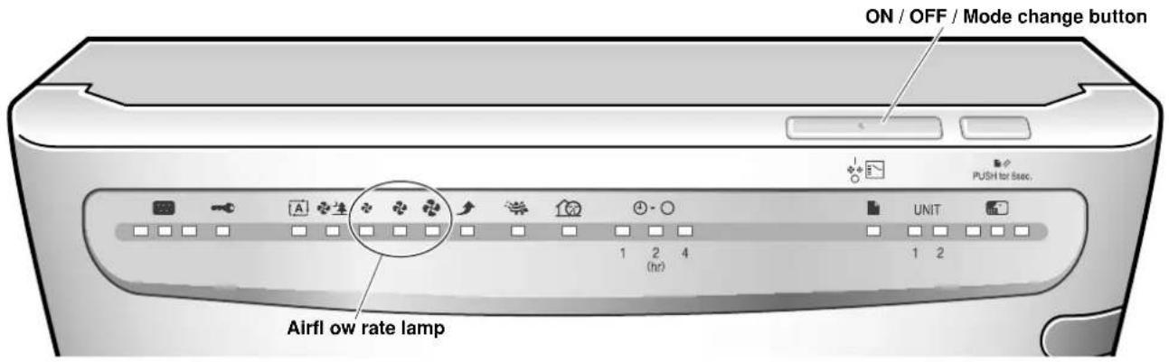
Press 1 on the unit for 10 seconds.
2 Witnessed, point the remote controller at the unit and
- The receiving tone sounds, one of the airflow rate lamps “♣ (Low)”, “♣ (Standard)” or “♣ (High)” blinks for 5 seconds, and then the lamp corresponding to the set sensitivity lights up.
Change the sensitivity using 3 on the unit.

• Each time the button is pressed, an airflow rate lamp lights up and the sensitivity change as below. The sensitivity setting is indicated by the airflow rate lamps.
If the airflow rate lamps do not change, disconnect the power plug, wait at least 3 seconds, reconnect the power plug and try the operation again from the beginning.
Toraise the sensitivity: → Select the “♣ (Low)” airflow rate lamp.
To lower the sensitivity: → Select the “(High)” airflow rate lamp.
| Airfl ow rate lamp | Sensitivity |
| “Low” | High |
| “Standard” | Normal |
| “High” | Low |
The sensor more readily reacts to dust.
Default setting
The sensor reacts less to dust.
4 When you decide on the setting, point the remote controller at the unit and press OFF TIMER
- The receiving tone sounds and the lamp corresponding to the set sensitivity blinks.
5 Remove the power plug while the set lamp is blinking, wait for 3 seconds or more, and then insert the power plug again.
NOTE
- The sensitivity of the air quality sensor can be set whether the unit is running or stopped.
- If step 5 is not performed, the unit does not go back to the normal operating mode.
If step 5 is performed in the middle of setting, the setting can not appropriately be completed.
Frequently Asked Questions
Before consulting your dealer, check the following points.

Troubleshooting
Before consulting your dealer or asking for repairs, check the following points.
If the problems still can not be solved, consult your dealer.
| The unit does not operate. | |
| The unit does not operate even if the ON / OFF button is pressed. | Is the front panel correctly set? ● Page 10.Are the projections on the rear of the front panel broken? ●Check the projections. ➔ Page 16.Consult your dealer if the projections are broken.Is the battery of the remote controller run down? ● Page 12. |
| The desired results are not obtained. | |
| The air is not cleaned. | Is the unit located where the air does not reach the entire roomor is something obstructing the airfl ow?Select an unobstructed location from where the air can reach theentire room.Is the prefilter, the pleated filter or UNIT1 dirty?Perform cleaning.→Page 15-21.If odour of the deodorising catalyst unit is a concern, lightly wetthe surface of the unit using an atomiser, and then dry it in ashaded and well-ventilated place. |
| Although there is odour, the green lamp remains lit. | Is a large amount of odour generated when starting operation of the unit?→The odour level of the initial 1 minute is used as the standard for the sensitivity of the odour sensor. Operate the unit with an increased airflow.→Page 8.Modify the standard sensitivity of the odour sensor using the following procedure.When the air is clean (when there is no odour), disconnect the power plug and wait for 3 or more seconds. Connect the power plug once again, and start operation. |
| Odour comes from the air outlet. | Is a large amount of odour generated temporarily? (i.e., many people are smoking, grilling meat, etc.)Operate the unit and the odour should gradually go away.Have you moved the unit from another room?The original room may have an odour.Operate the unit for a while.Are odours constantly generated in the room? (i.e., paint, new furniture, wall paper, sprays, cosmetics, chemicals, etc.)→odour that is constantly generated can not be completely removed, use the ventilation system in the room or operate the unit in a well-ventilated room for a while.You may smell an odour as ozone particles are generated.The amount is negligible, so it does not harm your health. |
Troubleshooting
Before consulting your dealer or asking for repairs, check the following points.
If the problems still can not be solved, consult your dealer.
| A sound is heard. | |
| A crackling or buzzing sound is heard during operation. | Are UNIT1 and UNIT2 correctly set?Insert UNIT1 until it clicks. ➔Insert UNIT2 completely to the end. Page 17-20.Is dust adhered to UNIT1 and UNIT2? Page 19, 20. |
| A fi zzing sound is heard during operation. | UNIT2 makes a hissing sound caused by the streamer discharge during operation.Depending on the usage conditions, the sound becomes lower or the sound quality may change, but this does not indicate any problem with operation.If the sound persists, change the installation site of the unit. |
| The lamp lights up or blinks. | |
| The airfl ow rate lamps blink simultaneously.The unit does not blow air. | Is there any obstacle in the air outlet? •Disconnect the power plug and remove the obstacle. Reconnect → the power plug and turn the power on.If the present condition does not change or you can not remove the obstacle, consult your dealer. |
| The “UNIT1” lamp or “UNIT2” lamp does not go off or light up again even after cleaning UNIT1 or UNIT2. | Are UNIT1 and UNIT2 set correctly? •Insert UNIT1 until it clicks. ➔Insert UNIT2 completely to the end. Page 17-20.• Are water drops, detergent, or bits of fibre left in UNIT1 and UNIT2 after cleaning?After cleaning, wash UNIT1 and UNIT2 well so as not to leave detergent or bits of fibre, and completely dry them.Are the ionised wires cut?Check the ionised wires. Consult your dealer for replacement with new ones. |
| The fi Iter lamp does not go off, although the pleated fi Iter is replaced. | • Did you press the filter reset button for 5 seconds?→ Even if the pleated filter is replaced, unless you press the filter reset button for 5 seconds, the filter lamp does not go off. Page 21. |
| Other | |
| There is a burn mark on the metal part of UNIT2. | This is a mark made by the streamer discharge and is not abnormal. |
| The TV picture is distorted. | Is a TV or radio installed within 2m of the unit or is an indoor antenna used close to the unit?Is the power supply cord or the antenna of the TV or radio close to the unit?Move the unit as far away from TVs, radios and antennas as possible. |
MEMO
DAIKIN INDUSTRIES, LTD.
Head office:
Umeda Center Bldg., 2-4-12, Nakazaki-Nishi,
Kita-ku, Osaka, 530-8323 Japan
Tokyo office:
JR Shinagawa East Bldg., 2-18-1, Konan,
Minato-ku, Tokyo, 108-0075 Japan
http://www.daikin.com/global_ac/
- Features
- About air purifying
- The powerful suction of a high airflow rate captures dust, pollen, etc.
- Deodorising and decomposing odour in the air
- The streamer discharge decomposes absorbed odour.
- What is the "Streamer" function?
- CONTENTS
- Read before Operation
- Operation
- Care and Cleaning
- Troubleshooting
- Safety Precautions
- WARNING
- CAUTION
- Precautions during use
- Streamer discharge and electric dust collection
- Name and Operation of Each Part
- Remote controller
- Unit display
- Airflow rate lamp (green)
- Air quality sensor lamp (dust sensor)
- Odour sensor lamp
- Preparation before Operation
- Accessories check ■
- How to attach the pleated ■ fi Iter
- Remove the front panel. 1
- Remove UNIT1.2
- Remove the deodorising catalyst unit.3
- Attach the pleated fi Iter. 4
- Attach the deodorising catalyst unit. 5
- Attach UNIT1.6
- Attach the front panel. 7
- Installation of the unit ■
- ATTENTION
- Hints for smart installation
- Do not use the unit in the following places.
- Preparation of remote controller
- A battery is already set in the remote controller.
- Battery replacement
- Insert the power plug into an electrical socket.
- How to use
- NOTE
- Battery
- How to Operate
- To start the operation
- To prevent mishandling by small children
- Childproof lock
- To operate the unit according to the cleanness level of the air
- Auto fan operation
- To clean the air in the room quickly
- Turbo operation
- To set the timer
- Timer operation
- Operation with the button on the unit
- Press
- To change the airflow manually
- Airflow manual operation
- To clean pollen
- Anti-pollen operation
- To operate quietly when you are sleeping
- Sleep mode operation
- To change the brightness of the unit display lamp
- BRIGHTNESS
- ■When any malfunction occurs during operation
- ■Start / Stop
- ■Auto fan operation
- ■Turbo operation
- ■Quiet operation
- ■Anti-pollen operation
- ■Sleep mode operation
- ■Timer operation
- ■Childproof lock
- Quick Reference Table of Maintenance
- Remove the parts for maintenance in numerical order.
- Removing and Attaching Each Part
- Remove
- Remove the prefi Iter.2
- Remove UNIT1.3
- Remove the deodorising catalyst unit.4
- Attach
- Attach the deodorising catalyst unit. 1
- Attach UNIT1.2
- Attach the prefilter.
- Attach the front panel.
- Removing and attaching the opposing pole plates ■
- Remove the opposing pole plates from 2 the rear of UNIT1.
- Attach the opposing pole plates. 1
- Attach UNIT1 and the front panel.2
- Cleaning of UNIT1 and UNIT2
- 1) Ionising frame
- 2) Ionised wire (8 locations)
- Wear rubber gloves when wiping or rubbing the units. ■
- 3) Streamer unit
- Replacement of the Pleated Filter
- Replace the pleated fi Iter with a new 2 fi Iter.
- Attach UNIT1 and the front panel.
- Connect the power plug.
- Press the filter reset button on the upper part of the front panel for 5 seconds.
- Options
- Sensitivity Setting of the Air Quality Sensor (dust sensor)
- Witnessed, point the remote controller at the unit and
- Change the sensitivity using 3 on the unit.
- When you decide on the setting, point the remote controller at the unit and press OFF TIMER
- Remove the power plug while the set lamp is blinking, wait for 3 seconds or more, and then insert the power plug again.
- Frequently Asked Questions
- MEMO
- DAIKIN INDUSTRIES, LTD.
Brand : DAIKIN
Model : MC70LPVM
Category : Air purifier