
ER1000R - Câble pour ordinateur et périphériques APC - Free user manual and instructions
Find the device manual for free ER1000R APC in PDF.


| Product Type | Power Cable for Computer and Peripherals |
| Brand | APC by Schneider Electric |
| Model | ER1000R |
| Category | Power Cable |
| Application | Connects 2–4 racks in row data centers |
| Cable Length | 5 m (16.4 ft) |
| Current Rating | 25 A |
| Cable Type | H05 VV-F (VDE approved) |
| Maximum Temperature | <70°C (158°F) |
| Conductor Size | 2.5 mm² |
| PDP Side Connector Type | CE040012 (Terminal block) |
| Rack PDU Connector Type | IEC309 16A 3P+N+E (Female) |
| Compatible PDU Models | EPDU1216B / EPDU1216M |
| Compatible Systems | APC Easy Rack PDP System (PDPMIB, PDPUPS, PDPPDU) |
| Safety Compliance | VDE, designed for professional installation per NEC/NFPA |
| Environmental Requirements | Ambient temperature 0–40°C, humidity 0–95% non-condensing |
| Storage Conditions | Indoor, temperature/humidity controlled, covered |
| Installation | Must be installed by qualified personnel; use cable access panel and cable protectors |
| Warranty | Two-year factory warranty (applies to PDP system, including cables) |
Frequently Asked Questions - ER1000R APC
User questions about ER1000R APC
0 question about this device. Answer the ones you know or ask your own.
Ask a new question about this device
Download the instructions for your Câble pour ordinateur et périphériques in PDF format for free! Find your manual ER1000R - APC and take your electronic device back in hand. On this page are published all the documents necessary for the use of your device. ER1000R by APC.
USER MANUAL ER1000R APC
Rack Mounted Power Distribution Panels fo Row Data Centers
Installation
PDPMIB1N-40, PDPMIB2N-20, PDPUPS1N-40, PDPUPS2N-20, PDPPDU-40
990-91537
September 2021
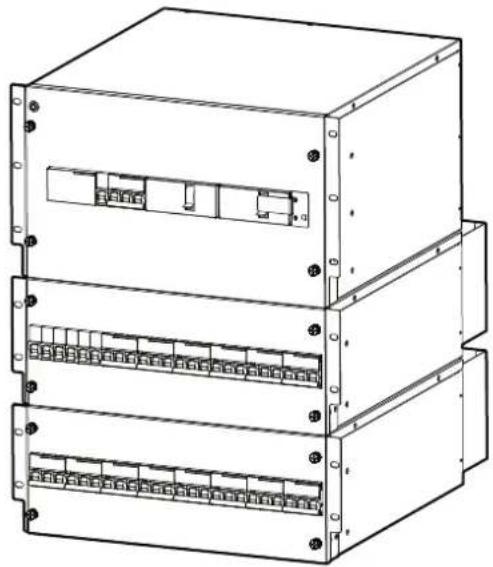
natural_image
Technical line drawing of a three-tiered server rack unit (no text or symbols)Legal Information
The Schneider Electric brand and any trademarks of Schneider Electric SE and its subsidiaries referred to in this guide are the property of Schneider Electric SE or its subsidiaries. All other brands may be trademarks of their respective owners.
This guide and its content are protected under applicable copyright laws and furnished for informational use only. No part of this guide may be reproduced or transmitted in any form or by any means (electronic, mechanical, photocopying, recording, or otherwise), for any purpose, without the prior written permission of Schneider Electric.
Schneider Electric does not grant any right or license for commercial use of the guide or its content, except for a non-exclusive and personal license to consult it on an "as is" basis. Schneider Electric products and equipment should be installed, operated, serviced, and maintained only by qualified personnel.
As standards, specifications, and designs change from time to time, information contained in this guide may be subject to change without notice.
To the extent permitted by applicable law, no responsibility or liability is assumed by Schneider Electric and its subsidiaries for any errors or omissions in the informational content of this material or consequences arising out of or resulting from the use of the information contained herein.
Table of Contents
General Information....5
Safety....5
Receiving the Equipment 6
Inventory....7
Installation....11
Tools Required 11
Installing Equipment 12
Mounting Rails 13
Cable Access Panel....14
System Components ....16
Configurations and Wiring 19
Wiring Considerations....24
Install the Safety Covers 26
System Startup....28
Maintenance Bypass Procedure 29
Troubleshooting ....31
Power Distribution Panel Electrical Diagrams 33
Specifications 39
Two-Year Factory Warranty....41
General Information
This manual provides instructions to install two configurations of the Power Distribution Panels (PDP) for the Easy Rack PDP System Cabinet. Each of the Maintenance Bypass Panels (MBP) and Power Distribution Panels (PDP) contain Mechanical Circuit Breakers (MCBs) that facilitate the transfer of power from the UPS to bypass operation to allow maintenance to be performed on the UPS. PDPPDU-40 also houses 8-MCBs for distributing power to load. Read these instructions carefully and observe all safety warnings and other precautions. Should you require any installation/operation service, parts, accessories, or maintenance, contact Schneider Electric Customer Support at www.se.com.
Safety
SAVE THESE INSTRUCTIONS
This manual contains important instructions that should be closely followed during installation, maintenance, and operation of the system. Read all safety and operating instructions before attempting to operate the system.
Adhere to all Warning labels on the unit, in this manual and in the attendant manuals for the system. Follow all operating and user instructions.
This product is not intended for use with life support or other designated “critical” devices. The maximum load must not exceed that shown on the rating label.
⚠️ DANGER
HAZARD OF ARC FLASH AND ELECTRICAL SHOCK
- Remove incoming power to the system before performing any work. Because of the UPS, live power exists within the equipment when power is turned off. always use a properly rated voltage sensing device to confirm there is no voltage in the system.
- Schneider Electric does NOT recommend performing maintenance to the Maintenance Bypass Panel with Power Distribution while power is live. Perform live maintenance at your own risk.
- Electrical equipment must be installed, operated, serviced, and maintained only by qualified personnel.
- The system must be installed in accordance with the National Electrical Code and all applicable local codes. This installation must comply with the requirements of ANSI/NFPA 75 and NEC/ NFPA 79 Art. 645.
- Perform appropriate Lock Out/Tag Out procedures during equipment installation and maintenance.
- Wear appropriate personal protective equipment (PPE) and follow safe electrical work practices. See NFPA 70E and follow all local codes and regulations.
- DO NOT remove the rear/side panels of the PDP, or any sheet metal not designed to be removed.
Failure to follow these instructions will result in death or serious injury.
NOTICE
EQUIPMENT DAMAGE
- Follow all wiring instructions precisely.
- Do not use caustic detergents or abrasive materials to clean the sheet metal. A damp, soft cloth is usually sufficient to remove dust or debris.
Failure to follow these instructions can result in equipment damage.
Receiving the Equipment
Upon receipt of the equipment, inspect for obvious signs of external damage.
NOTE: A thorough internal inspection should be conducted only after the unit has been positioned for installation and before making any electrical connections.
Acceptable Environmental Requirements
 |  |  |
| Ambient Temperature: -0° to 40°C (32° to 104°F) | Relative Humidity: 0–95% Non-condensing | Altitude: 0–2000 m (0–6560 ft) |
Storage Conditions:
| NOTICE |
| HAZARD OF EQUIPMENT DAMAGEIf the system will not be installed immediately, store the unit (covered) in indoor, temperature and humidity-controlled area, free of dirt, corrosive elements or conductive contaminants.Leaving the equipment uncovered and exposed to the elements will cause damage and void the factory warranty.Leaving the equipment uncovered and exposed to the elements will cause damage and void the factory warranty. When possible, leave the equipment on the pallet until you are ready to move it to its final location.Failure to follow these instructions can result in equipment damage |
Unpacking the System Components

Save the shipping materials for later use or dispose of them appropriately.
▲CAUTION
HEAVY EQUIPMENT HAZARD
Use at least two people when unpacking, lifting, and assembling this equipment.
Failure to follow these instructions can result in injury or equipment damage.
Inventory
PDPMIB1N-40 or PDPMIB2N-20
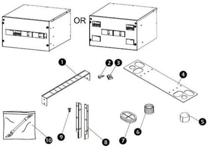
| Item Description | PDPMIB1N-40 | Quantity | PDPMIB2N-20 Quantity |
| 1 Cable manager 1 1 | |||
| 2 M6 x 12 Phillips pan head screw (in accessory bag) | 14 14 | ||
| 3 M6 Cage nut (in accessory bag) | 14 14 | ||
| 4 Top cable access panel 1 1 | |||
| 5 | Grommet cover (in accessory bag) | 2 | 2 |
| 6 Grommet (in accessory bag) | 1 | 2 | |
| 7 | Cable Protector (in accessory bag) | 4 | 4 |
| 8 Mounting brackets 2 | (1 Left, 1 Right) | 2 (1 Left, 1 Right) | |
| 9 M4 x 8 Flat head screw 8 8 | |||
| : | Wire accessories bag 1 1 |
Contents of Wire accessories bag: (not shown)
| Description PDPMIB1N-40 | Quantity | PDPMIB2N-20 Quantity |
| MBS WIRE 1 | — | |
| MAIN OP WIRE | 1 set | — |
| BYP OP WIRE | 1 set | — |
| MAIN OPA WIRE | — | 1 set |
| MAIN OP B WIRE | — | 1 set |
PDPUPS1N-40 or PDPUPS2N-20
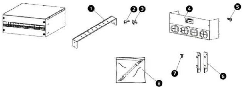
| Item Description | PDPUPS1N-40 | Quantity | PDPUPS2N-20 Quantity |
| 1 Cable manager | 1 1 | ||
| 2 M6 x 12 Phillips pan head screw(in accessory bag) | 8 | 8 | |
| 3 M6 Cage nut | (in accessory bag) | 8 | 8 |
| 4 Rear safety access panel (not assembled)(includes 4 cable protectors installed) | 1 | 1 | |
| 5 M4 x 8 Phillips pan head screw(in accessory bag)(for rear safety access panel assembly) | 2 | 2 | |
| 6 Mounting brackets | 2 | (1 Left, 1 Right) | 2(1 Left, 1 Right) |
| 7 M4 x 8 Flathead screw | 8 8 | ||
| 8 Wire accessories bag | 1 1 | ||
Contents of Wire accessories bag: (not shown)
| Description PDPUPS1N-40 | Quantity | PDPUPS2N-20 Quantity |
| OP 1 WIRE 1 set | — | |
| OP 2 WIRE 1 set | — | |
| OP A WIRE | — | 1 set |
| OP B WIRE | — | 1 set |
| TERMINAL 35 25 |
PDPPDU-40
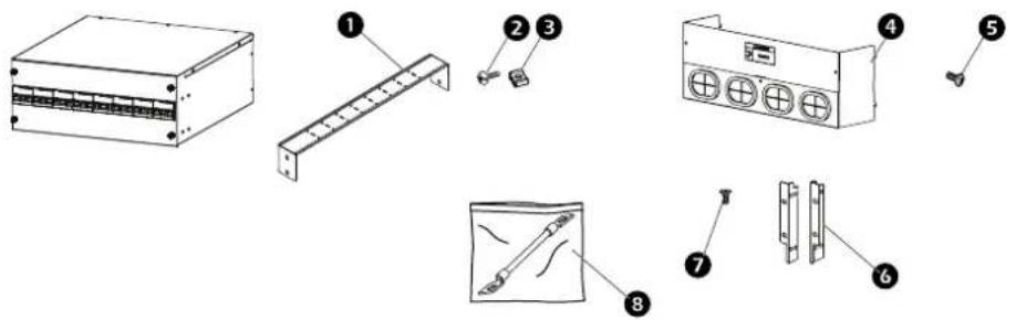
| Item Description Quantity | ||
| 1 Cable manager 1 | ||
| 2 M6 x 12 Phillips | pan head screw(in accessory bag) | 8 |
| 3 M6 Cage nut | (in accessory bag) | 8 |
| 4 Rear safety access panel (not assembled)(includes 4 cable protectors installed) | 1 | |
| 5 M4 x 8 Phillips | pan head screw(in accessory bag)(for rear safety access panel assembly) | 2 |
| 6 Mounting brackets | 2 | (1 Left, 1 Right) |
| 7 M4 x 8 Flat head | screw 8 | |
| 8 Wire accessories | pag 1 | |
Power Cables
Power cables are required to connect the PDP system to other racks in the row. Your configurator can determine which power cables are necessary for your row.
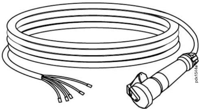
natural_image
Line drawing of a coiled cable with connectors and a cylindrical connector (no text or symbols)| Cable | ||||||
| SKU Applica- | tion | Cable Length (m) | Current Rating (A) | Type Maximum | Temperature | Size |
| ER1000R 2–4 racks | 5 25 H05 | VV-F | VDE | <70°C 2.5 mm ^2 | ||
| ER1001R 5–6 racks | 7 25 H05 | VV-F | VDE | <70°C 2.5 mm ^2 | ||
| ER1002R 7–8 racks | 9 25 H05 | VV-F | VDE | <70°C 2.5 mm ^2 | ||
| continued Connector | |||
| SKU PDP Side | Terminal Type | Rack PDU Connector Type | PDU Type |
| ER1000R CE040012 | IEC309 16A | 3P + N + E (Female) | EPDU1216B/EPDU1216M |
| ER1001R CE040012 | IEC309 16A | 3P + N + E (Female) | EPDU1216B/EPDU1216M |
| ER1002R CE040012 | IEC309 16A | 3P + N + E (Female) | EPDU1216B/EPDU1216M |
Installation
Tools Required
(not provided)
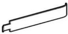 | Cage Nut Tool |
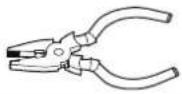 | Pliers |
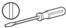 | Flat tip screwdriver |
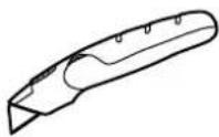 | Box cutter knife |
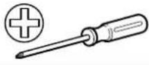 | Phillips head screwdriver |
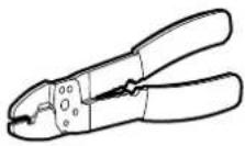 | Wire crimping tool |
Installing Equipment
Using Cage Nuts:
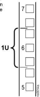
- Locate the top and bottom U-space on the vertical mounting rails. Every third hole on the mounting rails is numbered to indicate the middle of a U-space.
• Install the cage nuts on the interior of the vertical mounting rail, then install the equipment.
▲CAUTION
FALLING EQUIPMENT HAZARD
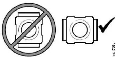
Do NOT install cage nuts vertically with the tabs engaging the top and bottom of the square hole.
Failure to follow these instructions can result in injury or equipment damage.
• Install cage nuts horizontally, with the tabs engaging the sides of the square hole.
• Install the cage nuts on the interior of the vertical mounting rail.
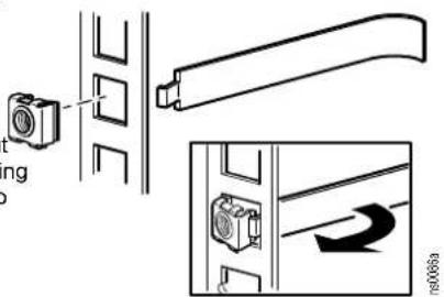
Install a cage nut:
- From the inside of the cabinet, insert the cage nut into the square hole on the vertical mounting flange.
- Hook one of the tabs on the cage nut through the far side of the hole.
- Place the cage nut tool into the cage nut from the other side of the vertical mounting flange and pull to snap the cage nut into position.
Remove a cage nut:
- Remove any attached screw.
- Grasp the cage nut and squeeze the tab sides. Push the cage nut through the square hole in the vertical mounting flange to release it.
Mounting Rails
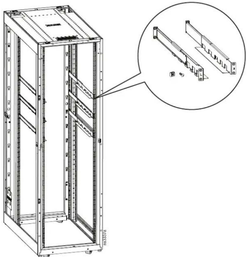
The PDP system is installed in an Easy Rack using Rail Kits SRVSRK1. The Rail Kits include one rail for the Left side and one rail for the Right side of the rack. T rails are clearly marked L and R. M6 cage nuts and M6 screws are included in the kit. Position the rails in the Easy Rack at the U-spaces you have pre-determined for this system.
natural_image
Technical line drawing of a server rack cabinet with an inset showing internal components (no text or symbols)The illustration above shows the Easy Rack with doors and side panels removed for clarity.
Cable Access Panel
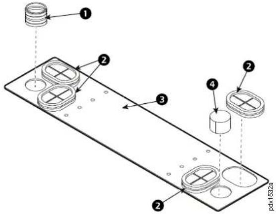
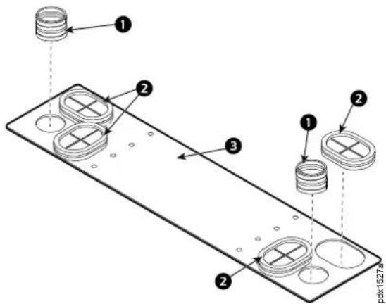
- Install the cable protectors (2), grommet(s) (1), and grommet covers (4) as required for your system's configuration into the cable access panel (3).
1N Configuration:
2N Configuration:
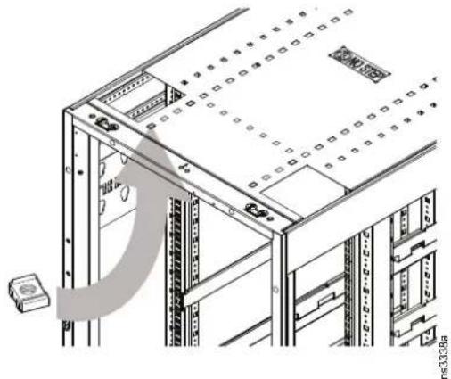
- Install four (4) cage nuts (from the hardware bag) to the roof of the Easy Rack by inserting the cage nuts from inside the roof and pulling them through the square holes to secure them. See the instructions in the Equipment Installation section of this manual for more information.
natural_image
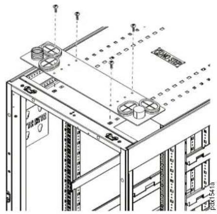
Technical line drawing of a server rack with ventilation duct and mounting bracket (no text or symbols)- Install four (4) M6 Phillips head screws (from the hardware bag) to secure the Cable Access Panel to the roof.
natural_image
Technical line drawing of a server rack with mounting holes and wiring (no text or symbols)System Components
Install the Brackets to the PDP System Component
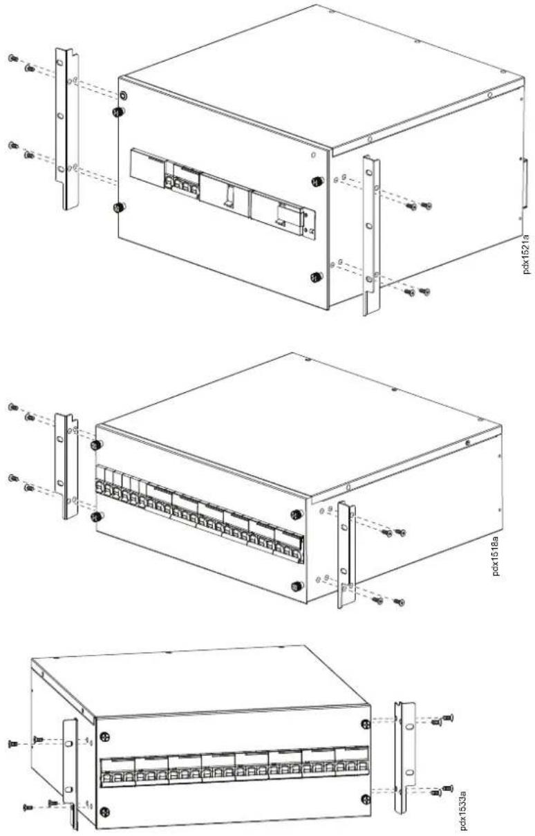
Install the brackets from the hardware bag to the system components using the M4 x 8 Flat head screws included.
Eight (8) screws are required to install the brackets.
Install the System Components to the Rack
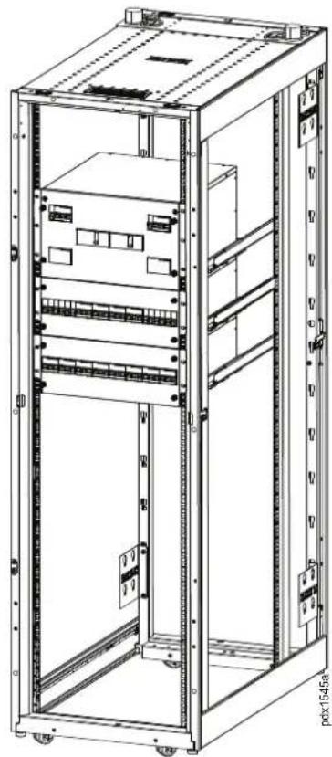
Install the system components on the rails intended for each starting with the PDPPDU-40 in the lowest rack position. Use the M6 cage nuts and M6 screws included in the hardware bag to secure each component to the Easy Rack.
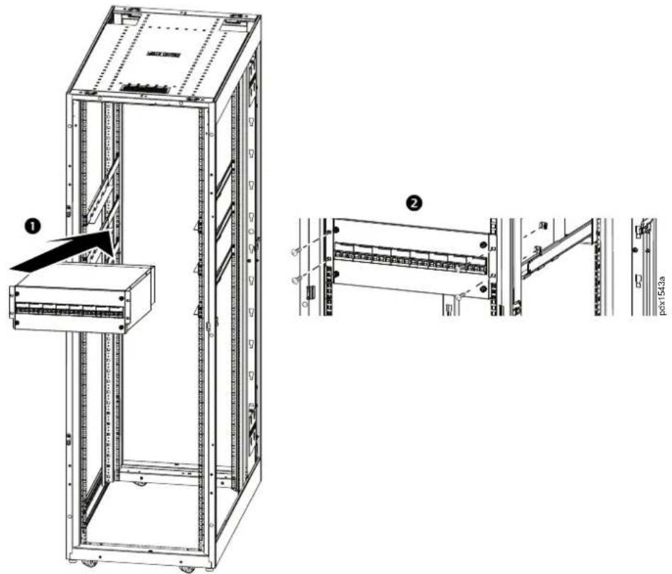
Install all three components of the PDP system in your rack.
natural_image
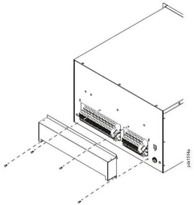
Technical line drawing of a server rack cabinet with visible internal components and mounting hardware (no text or labels)Remove the Safety Cover from PDPMIB1N-40 or PDPMIB2N-20
To prepare for wiring the PDPs, remove the four (4) screws and lift the safety cover from the back of PDPMIB1N-40 or PDPMIB2N-20.
natural_image
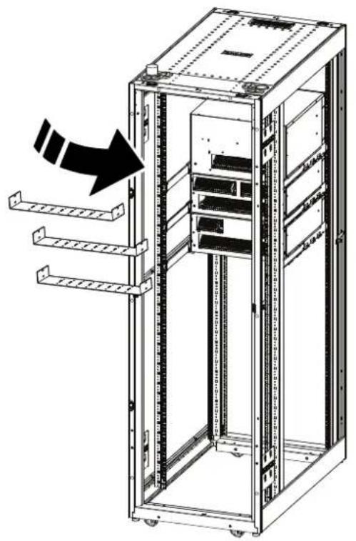
Technical line drawing of an electronic device enclosure with internal components and wiring (no text or symbols)Install the Cable Managers
Use four (4) M6 cage nuts and four (4) M6 screws to install each cable manager to the Vertical Mounting Flanges at the rear of the PDPs as shown in the illustration.
natural_image
Technical line drawing of a server rack cabinet with multiple racks and a directional arrow indicating assembly (no text or symbols present)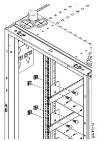
Configurations and Wiring
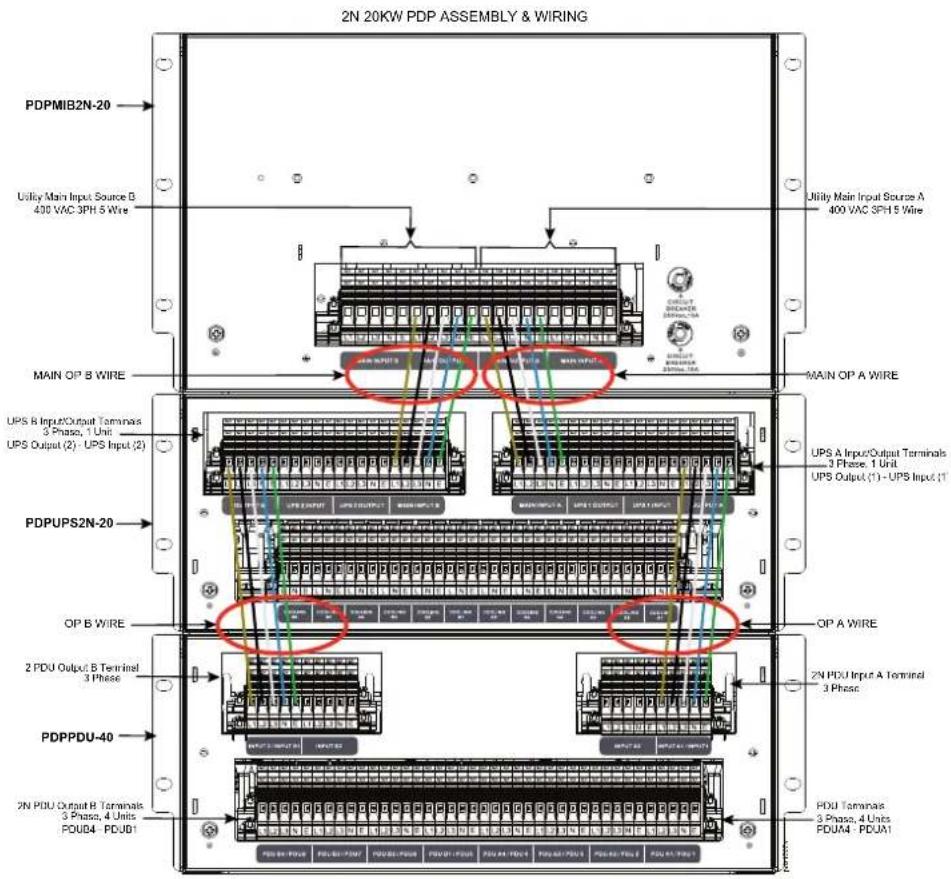
Complete wiring the PDP components using the wiring diagrams in the Power Distribution Panel Electrical Diagrams Chapter in this manual.
1N Configuration
Front View:
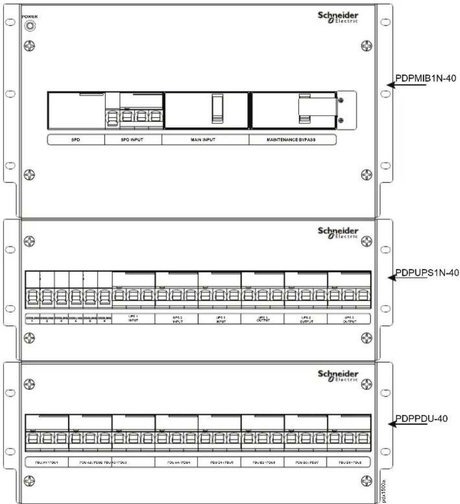
Rear View:
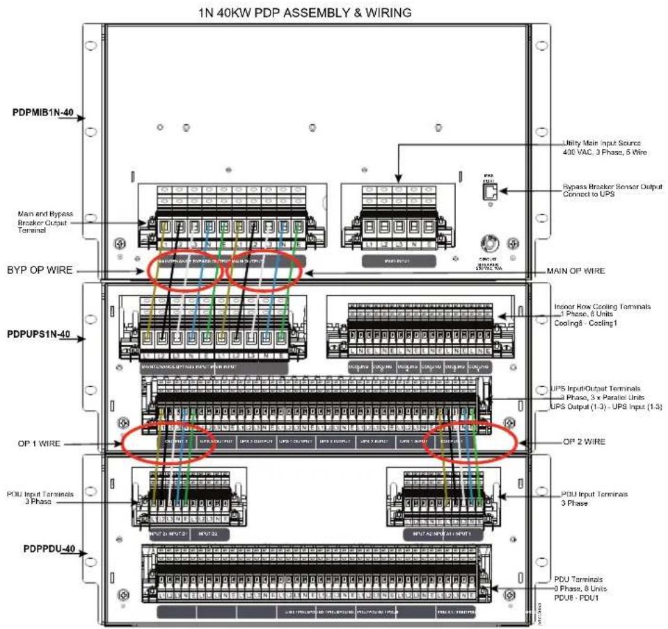
2N Configuration
Front View:
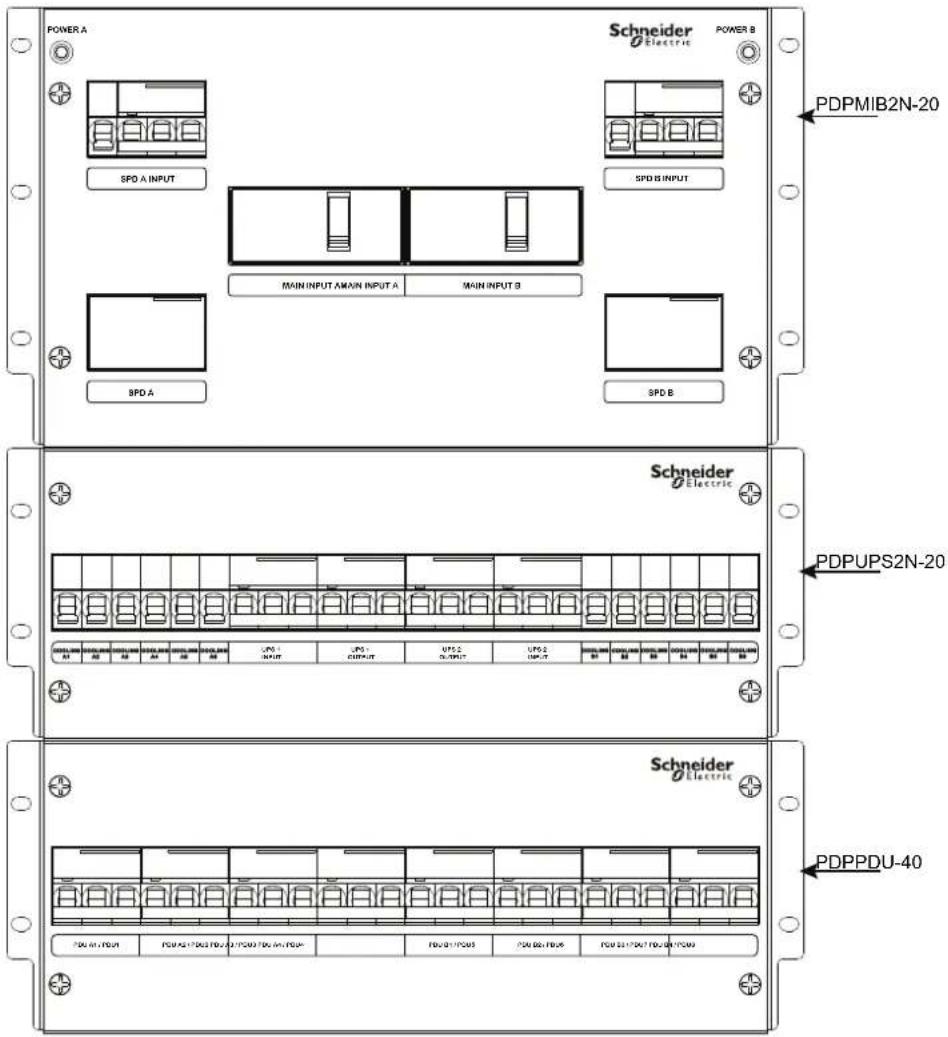
Rear View:
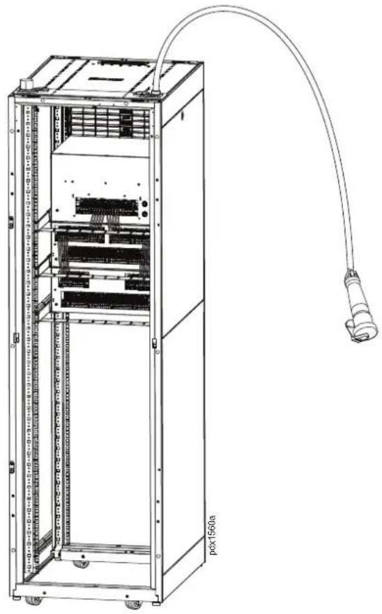
Install the Power Cables
Power cables (ER1000R, ER1001R, and ER1002R) are installed through the cable access panel on the roof and wired as shown in the wire diagrams in the Power Distribution Panel Electrical Diagrams Chapter in this manual.
natural_image
Technical line drawing of a server rack cabinet with attached cable, showing internal components and mounting holes (no text or labels)Wiring Considerations
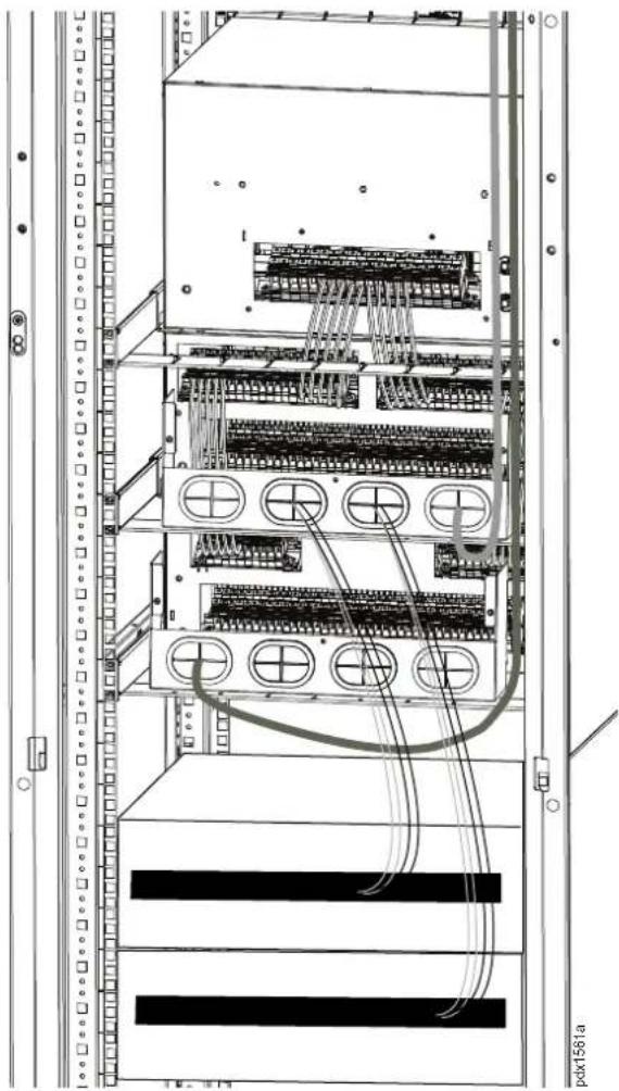
Wiring from the UPS should be installed through the cable protectors in the back of the safety covers of the PDPUPS1N-40 or PDPUPS2N-20, and PDPPDU40. To do this, place the bottom half of the safety covers on the cable managers. Do not assemble the top half of the safety cover at this time. Do not attach the safety covers at this time.
natural_image
Technical line drawing of a server rack with multiple connected modules and wiring (no text or symbols)NOTICE
- Recommended input cable size for PDPMIB1N-40 : 2AWG
- Recommended input cable size for PDPMIB2N-20: 6AWG
- Terminal accessories are provided to assemble UPS input and output cables.
Failure to follow these instructions can result in equipment damage.
NOTICE
- Recommended UPS Input and Output cable size is 10 ~mm^2 (not provided).
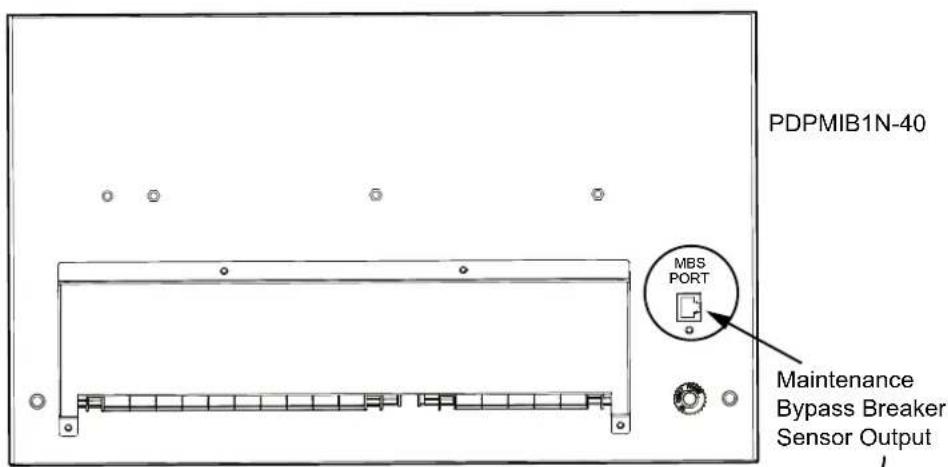
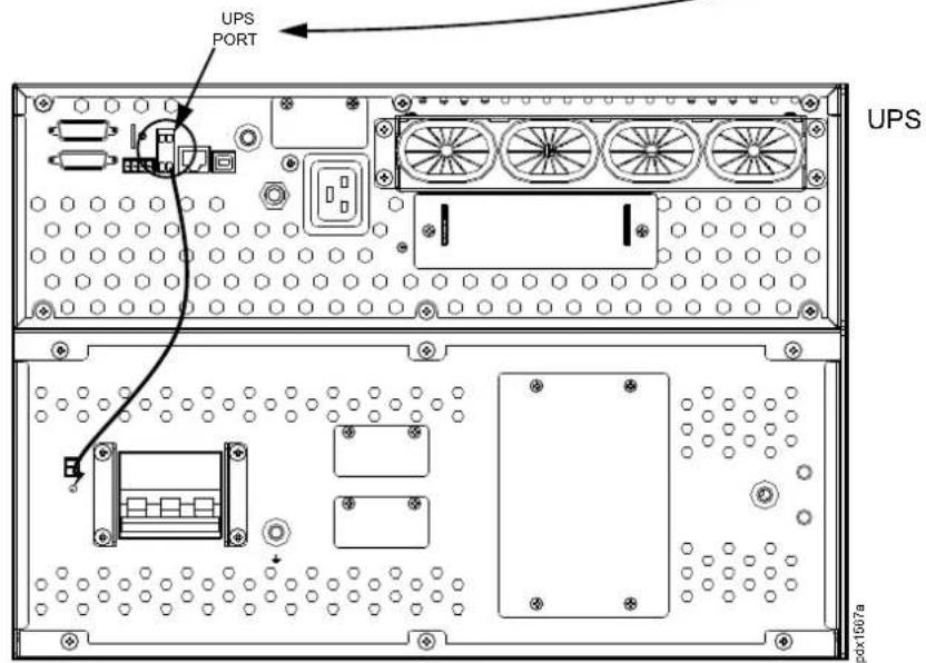
- Use the Accessory MBS Wire to make the connection from the MBS Port on PDPMIB1N-40 to the UPS MBS Port on the UPS.
- Refer to the UPS Installation manual for complete instructions.
Failure to follow these instructions can result in equipment damage.
MBS Wire for PDPMIB1N-40

PDP and UPS MBS Ports
Install the Safety Covers
⚠️ DANGER
SHOCK HAZARD
Do not operate this equipment with safety covers removed.
Failure to follow these instructions will result in death or serious injury.
All three safety covers must be installed to the rear of the PDPs.
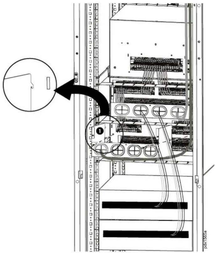
The bottom halves of the safety covers for PDPUPSN1-40, PDPUPSN2-20, and PDPPDU-40 are attached to the back of the PDPs with 2 screws and tabs that fit into slots in the back of the PDPs. See the illustration below.
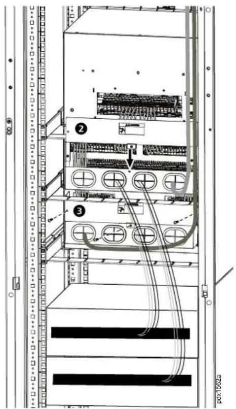
The top halves of the safety covers are now installed. Position the top half to the bottom half ^2 . Use the three screws (provided) to attach the top half to the bottom half of the safety cover.
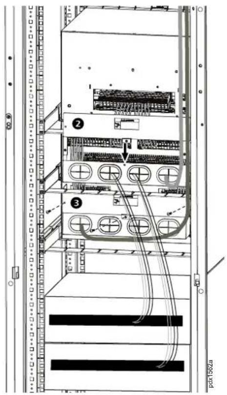
Install the safety cover to PDPMIB1N-40 or PDPMIB2N-20. Insert the tabs on the safety covers into the slots in the back of the PDP then use the four (4) screws (provided) to secure the safety cover to the rear of the PDP.
System Startup
System Cabinet Preparations
- Ensure the PDPs are properly installed in the rack. Refer to the installation instructions.
- Ensure the PDP power cables have been properly installed. See the wiring and terminal allocation drawing.
- Ensure the UPS and External Battery Packs have been properly installed in the rack. Refer to the UPS installation manual for installation instructions.
- Ensure the Cooling System is properly installed and cooling power input cables are connected to the assigned power terminals. Refer to the wiring and terminal allocation drawing.
- Ensure the PDU cables have been properly installed to the assigned power terminals. See the PDP wiring and terminal allocation drawing.
- Connect the PDP Main Input Cable to the assigned terminals and the Main Utility Distribution Panel. See the PDP wiring and terminal allocation drawing.
System Inspection
- Check, measure, and confirm that the upstream mains voltage and frequency are normal. Ensure there are no wiring errors or anomalies.
- Check, measure, and confirm that the distribution cables of the UPS and PDP are correctly connected.
- Check that the air conditioner is charged with refrigerant.
- Check that all the communication cables are connected correctly according to the wiring diagram.
- Check that the air conditioner pipes are properly connected and that there are no leaks.
- Verify that the power terminal connections are connected properly and the screws are torqued to the correct rating.
Startup and Commissioning
- Close the Main Utility Power Distribution Breaker. Check that the PDP1 light is ON.
- Close the UPS External Battery Circuit Breaker.
- Close the UPS INPUT MCB. Power ON the UPS. Then, check that the UPS output voltage and frequency is normal without any fault indicator.
- Close all UPS OUTPUT MCBs. Close all PDU MCBs and verify all output voltages are within normal operating range.
- Close all Indoor and Outdoor Cooling MCBs and verify successful Cooling System Start-up.
- Verify Cooling Performance.
Maintenance Bypass Procedure
1N Maintenance Bypass Procedure
This procedure is for the UPS system in the maintenance bypass-operating mode (System is on External Maintenance Bypass) with 1N input wiring configuration.
- Remove the cover on the Maintenance Bypass MCB. This will force the UPS to automatically switch to operate in Static Bypass Mode. Check and ensure that the UPS is operating in Static Bypass Mode.
- Turn ON the Maintenance Bypass MCB.
- Turn OFF the UPS INPUT MCB and UPS OUTPUT MCB.
- Turn OFF the UPS and disconnect the Input and Output wiring in the PDP rear panel.
- Turn OFF all External Battery Pack Circuit Breakers.
- Disconnect the UPS Battery Cable.
- Allow a service engineer to replace or repair the UPS.
- Install the UPS and connect the Input and Output wiring to the PDP rear panel.
- Install the UPS External Battery Pack Cable.
- Verify that all wiring installations are connected properly.
- Turn ON External Battery Pack MCB.
- Turn ON the UPS INPUT MCB and Power ON the UPS.
- Set the UPS to bypass mode. Follow the instructions in your UPS manual.
- Turn ON the UPS OUTPUT MCB.
- Turn OFF the Maintenance Bypass MCB and install the cover.
- Turn ON the UPS and verify that the UPS operation and the Output voltage is within normal operating range.
2N Maintenance Bypass Procedure
This procedure is for placing the UPS system in the Maintenance Bypass-Operating Mode (the System is on External Maintenance Bypass) in systems with the 2N input wiring configuration.
- Turn OFF the UPS INPUT MCB and the UPS OUTPUT MCB.
- Turn OFF the UPS.
- Turn OFF all External Battery Pack Circuit Breakers.
- Disconnect the Input and Output wiring in the PDP rear panel.
- Disconnect the UPS Battery Cable.
- Allow a service engineer to repair or replace the UPS.
- Install the UPS and connect the Input and Output wiring to the PDP rear panel.
- Install UPS External Battery Pack Cable.
- Verify that all wiring installations are connected properly.
- Turn ON the External Battery Pack MCB.
- Turn ON the UPS INPUT MCB and Power ON the UPS.
- Turn ON the UPS OUTPUT MCB.
- Turn ON the UPS and verify the UPS operation and the Output Voltage is within normal operating range.
Troubleshooting
| Problem Possible Cause Solution | ||
| Ambient high temperature alarm | Cooling unit does not supply cold air | Ensure no alarms are indicated on the cooling unit's Web UI or display. If there are no alarms, call the Schneider Electric service hotline. |
| System overload Confirm that | the actual load is over the rated power. If an overload situation exists, call the Schneider Electric service hotline. | |
| The rack doors are not properly closed, causing the cooling leakage. | Check the rack doors and confirm that all doors are closed properly. | |
| Excessively high external ambient temperature. | Confirm the high-temperature alarm threshold of the temperature sensor is reasonable and the ambient temperature is exceeding the threshold setting. Call the Schneider Electric service hotline. | |
| Door sensor alarm The sealed | doors of the rack are not closed. | Close all the doors properly. If closing the doors does not eliminate the alarm call the Schneider Electric service hotline. |
| Interior light does not illuminate when the door is opened. | The door sensor is out of position to make contact. | Check that no cables or equipment in the rack are interfering with the door sensor. If no interference is detected, and the light is still off, call the Schneider Electric service hotline. |
| Power cable to the interior light is disconnected or loose. | Ensure that the cable is properly connected. If the cable connection is secure and the light is still off, call the Schneider Electric service hotline. | |
| No power on the PDU Breaker | The UPS is not turned on. | Check the UPS display to ensure the UPS is turned on. If not, turn the UPS on. |
| The Main PDP1 and UPS MC is not closed. | Close the Main PDP1 and UPS MCB. | |
| Power cable connection to the PDP is loose. | Secure the power cable connection to the PDP. | |
| Emergency door opening does not activate during an overtemperature protection event. | Temperature sensor or door sensor error. | Check the temperature and door sensors. Replace the sensors. |
| Emergency door power supply or cable error. | Ensure the emergency door power supply and cable assembly are properly connected and functioning properly. If the power supply or cable assembly are not functioning, call the Schneider Electric service hotline. | |
| Cooling alarm Internal alarm event | Call the Schneider Electric service hotline. | |
| UPS alarm Internal alarm event | Call the Schneider Electric | service hotline. |
| UPS overload alarm The load | exceeds the maximum power threshold setting. | Check and confirm that the actual total power load does not exceed the threshold setting. If the power load exceeds the threshold setting, call the Schneider Electric service hotline. |
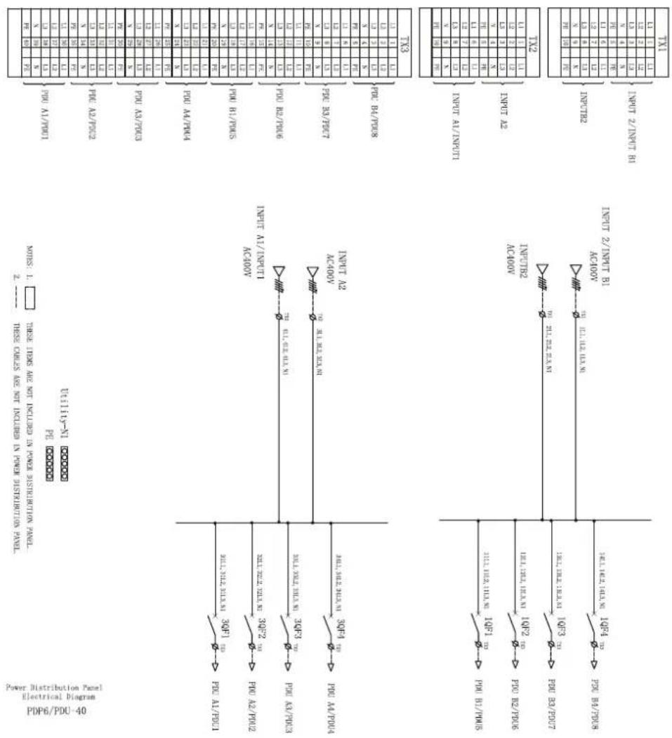
Power Distribution Panel Electrical Diagrams
PDPMIB1N-40
NOTES: 1. ☐ THIS ITEMS ARE NOT INCLUDED IN YOUR DISTRIBUTION PANEL. 2. --- THESE CHARLES ARE NOT INCLUDED IN YOUR DISTRIBUTION PANEL.
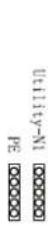
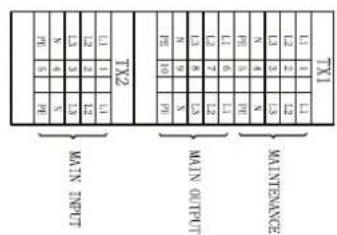
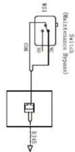
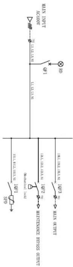
| A10 | NILLI/STOCK | S11 | TIME | CODE NAME | MIN |
| 1 | 2006/09/20 | 5:15 | NO | QD | 1 |
| 2 | 0009/009 | 00:00:00V | 1:00/1:00 | LFD/1:00 | 2 |
| 3 | 0009/009 | 00:00:00V | 0:00/0:00 | LFD/0:00 | 3 |
| 4 | 0009/009 | 00:00:00V | 0:00 | GDS | 4 |
PDP1/PDPMIBIN-40
Power Distribution Panel
Electrical Diagram
PDPMIB2N-20
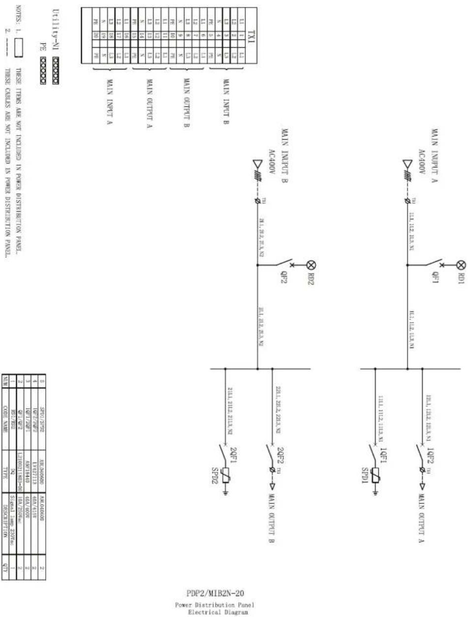
THIS THES ARE NOT INCLUDED IN POWER DISTRIBUTION PANEL.
2. ----
THIS CALLS ARE NOT INCLUDED IN POWER DISTRIBUTION PANEL.
NOTES: 1.
| MIN | CODE NAME | TYPE | DESCRIPTION NO. | QTY |
| 1 | 40#/30# | 70# | SINGLE LIME 3250KNC | 1 |
| 2 | 6#T/6#Z | 1210021801200-08 | 10A/5250V | 2 |
| 3 | 10#T/12#T | A9748140 | 60A/600V | 2 |
| 4 | 12#T/12#Z | 14742712 | 40A/4570 | 2 |
| 5 | 50#T/50#Z | A9640600 | A9640600 | 2 |
PDP2/MIB2N-20
Power Distribution Panel
Electrical Diagram
PDPUPS1N-40
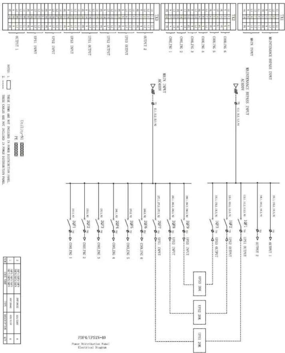
flowchart
graph TD
    A["Power Distribution Panel"] --> B["Main Unit"]
    B --> C["Main Unit switch"]
    C --> D["Control Logic"]
    D --> E["Main Unit switch 1"]
    D --> F["Main Unit switch 2"]
    D --> G["Main Unit switch 3"]
    D --> H["Main Unit switch 4"]
    D --> I["Main Unit switch 5"]
    D --> J["Main Unit switch 6"]
    D --> K["Main Unit switch 7"]
    D --> L["Main Unit switch 8"]
    D --> M["Main Unit switch 9"]
    D --> N["Main Unit switch 10"]
    D --> O["Main Unit switch 11"]
    D --> P["Main Unit switch 12"]
    D --> Q["Main Unit switch 13"]
    D --> R["Main Unit switch 14"]
    D --> S["Main Unit switch 15"]
    D --> T["Main Unit switch 16"]
    D --> U["Main Unit switch 17"]
    D --> V["Main Unit switch 18"]
    D --> W["Main Unit switch 19"]
    D --> X["Main Unit switch 20"]
    D --> Y["Main Unit switch 21"]
    D --> Z["Main Unit switch 22"]
    D --> AA["Main Unit switch 23"]
    D --> AB["Main Unit switch 24"]
    D --> AC["Main Unit switch 25"]
    D --> AD["Main Unit switch 26"]
    D --> AE["Main Unit switch 27"]
    D --> AF["Main Unit switch 28"]
    D --> AG["Main Unit switch 29"]
    D --> AH["Main Unit switch 30"]
    D --> AI["Main Unit switch 31"]
    D --> AJ["Main Unit switch 32"]
    D --> AK["Main Unit switch 33"]
    D --> AL["Main Unit switch 34"]
    D --> AM["Main Unit switch 35"]
    D --> AN["Main Unit switch 36"]
    D --> AO["Main Unit switch 37"]
    D --> AP["Main Unit switch 38"]
    D --> AQ["Main Unit switch 39"]
    D --> AR["Main Unit switch 40"]
    D --> AS["Main Unit switch 41"]
    D --> AT["Main Unit switch 42"]
    D --> AU["Main Unit switch 43"]
    D --> AV["Main Unit switch 44"]
    D --> AW["Main Unit switch 45"]
    D --> AX["Main Unit switch 46"]
    D --> AY["Main Unit switch 47"]
    D --> AZ["Main Unit switch 48"]
    D --> BA["Main Unit switch 49"]
    D --> BB["Main Unit switch 50"]
    D --> BC["Main Unit switch 51"]
    D --> BD["Main Unit switch 52"]
    D --> BE["Main Unit switch 53"]
    D --> BF["Main Unit switch 54"]
    D --> BG["Main Unit switch 55"]
    D --> BH["Main Unit switch 56"]
    D --> BI["Main Unit switch 57"]
    D --> BJ["Main Unit switch 58"]
    D --> BK["Main Unit switch 59"]
    D --> BL["Main Unit switch 60"]
    D --> BM["Main Unit switch 61"]
    D --> BN["Main Unit switch 62"]
    D --> BO["Main Unit switch 63"]
    D --> BP["Main Unit switch 64"]
    D --> BQ["Main Unit switch 65"]
    D --> BR["Main Unit switch 66"]
    D --> BS["Main Unit switch 67"]
    D --> BT["Main Unit switch 68"]
    D --> BU["Main Unit switch 69"]
    D --> BV["Main Unit switch 70"]
    D --> BW["Main Unit switch 71"]
    D --> BX["Main Unit switch 72"]
    D --> BY["Main Unit switch 73"]
    D --> BZ["Main Unit switch 74"]
    D --> CA["Main Unit switch 75"]
    D --> CB["Main Unit switch 76"]
    D --> CC["Main Unit switch 77"]
    D --> CD["Main Unit switch 78"]
    D --> CE["Main Unit switch 79"]
    D --> CF["Main Unit switch 80"]
    D --> CG["Main Unit switch 81"]
    D --> CH["Main Unit switch 82"]
    D --> CI["Main Unit switch 83"]
    D --> CJ["Main Unit switch 84"]
    D --> CK["Main Unit switch 85"]
    D --> CL["Main Unit switch 86"]
    D --> CM["Main Unit switch 87"]
    D --> CN["Main Unit switch 88"]
    D --> CO["Main Unit switch 89"]
    D --> CP["Main Unit switch 90"]
    D --> CQ["Main Unit switch 91"]
    D --> CR["Main Unit switch 92"]
    D --> CS["Main Unit switch 93"]
    D --> CT["Main Unit switch 94"]
    D --> CU["Main Unit switch 95"]
    D --> CV["Main Unit switch 96"]
    D --> CW["Main Unit switch 97"]
    D --> CX["Main Unit switch 98"]
    D --> CY["Main Unit switch 99"]
    D --> CZ["Main Unit switch 100"]
PDPUPS2N-20
NOTES: 1.
THESE ITEMS ARE NOT INCLUDED IN POWER DISTRIBUTION PANEL.
2.
3d
IN-611110
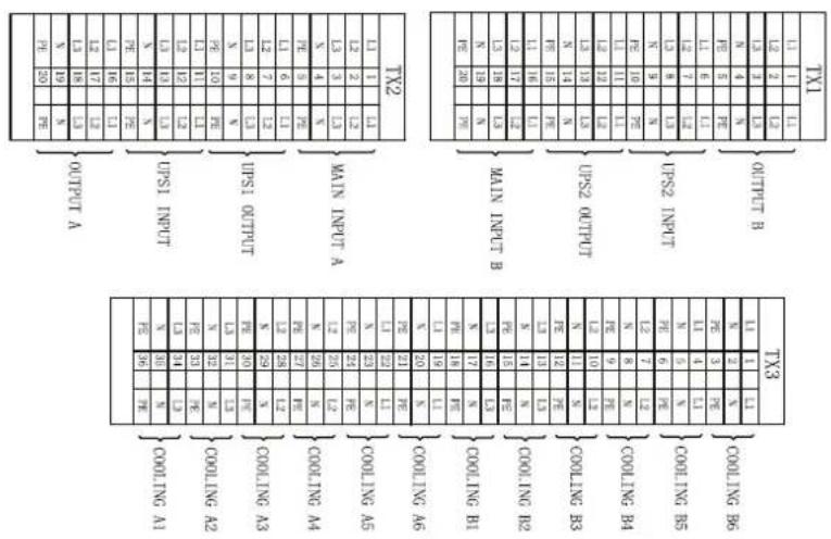
Power Distribution Panel Electrical Diagram
PDP5/UPS2N-20
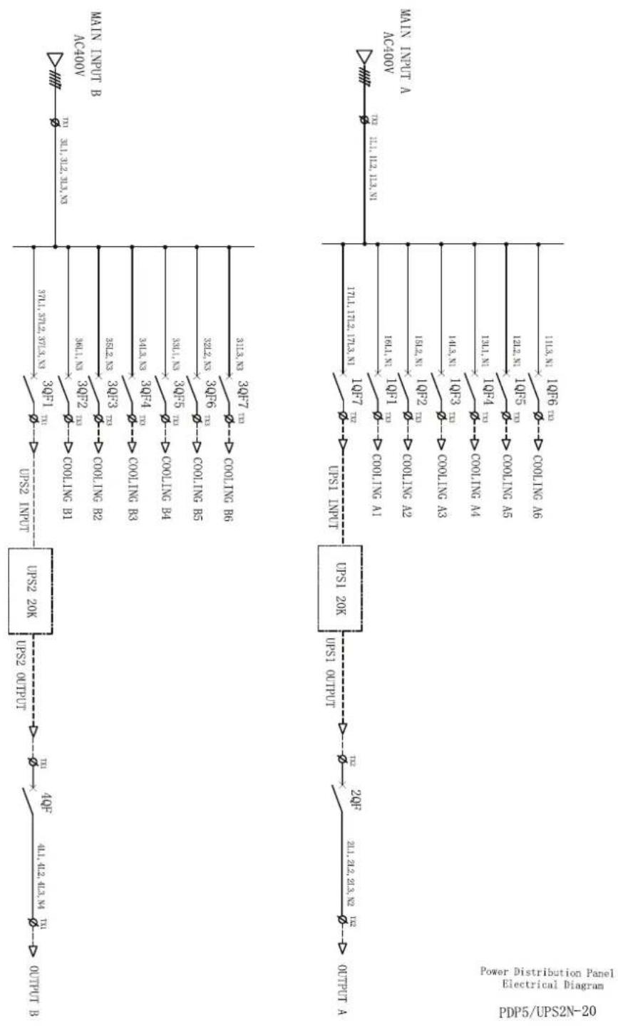
flowchart
graph TD
    A["MAIN INPUT A"] --> B["IC400"]
    B --> C["AC400"]
    D["Power Distribution Panel"] --> E["PDP5/IPS2N-20"]
    E --> F["Electrical Diagram"]
    G["UPS1 INPUT"] --> H["UPS1 20K"]
    H --> I["Output B"]
    J["UPS2 20K"] --> K["UPS2 INPUT"]
    K --> L["3Q9F1 TX1"]
    K --> M["3Q9F2 TX3"]
    K --> N["3Q9F3 TX5"]
    K --> O["3Q9F4 TX7"]
    K --> P["3Q9F5 TX8"]
    K --> Q["3Q9F6 TX9"]
    K --> R["3Q9F7 TX10"]
    K --> S["3Q9F8 TX11"]
    K --> T["3Q9F9 TX12"]
    K --> U["3Q9F10 TX13"]
    K --> V["3Q9F11 TX14"]
    K --> W["3Q9F12 TX15"]
    K --> X["3Q9F13 TX16"]
    K --> Y["3Q9F14 TX17"]
    K --> Z["3Q9F15 TX18"]
    K --> AA["3Q9F16 TX19"]
    K --> AB["3Q9F17 TX20"]
    K --> AC["3Q9F18 TX21"]
    K --> AD["3Q9F19 TX22"]
    K --> AE["3Q9F20 TX23"]
    K --> AF["3Q9F21 TX24"]
    K --> AG["3Q9F22 TX25"]
    K --> AH["3Q9F23 TX26"]
    K --> AI["3Q9F24 TX27"]
    K --> AJ["3Q9F25 TX28"]
    K --> AK["3Q9F26 TX29"]
    K --> AL["3Q9F27 TX30"]
    K --> AM["3Q9F28 TX31"]
    K --> AN["3Q9F29 TX32"]
    K --> AO["3Q9F30 TX33"]
    K --> AP["3Q9F31 TX34"]
    K --> AQ["3Q9F32 TX35"]
    K --> AR["3Q9F33 TX36"]
    K --> AS["3Q9F34 TX37"]
    K --> AT["3Q9F35 TX38"]
    K --> AU["3Q9F36 TX39"]
    K --> AV["3Q9F37 TX40"]
    K --> AW["3Q9F38 TX41"]
    K --> AX["3Q9F39 TX42"]
    K --> AY["3Q9F40 TX43"]
    K --> AZ["3Q9F41 TX44"]
    K --> BA["3Q9F42 TX45"]
    K --> BB["3Q9F43 TX46"]
    K --> BC["3Q9F44 TX47"]
    K --> BD["3Q9F45 TX48"]
    K --> BE["3Q9F46 TX49"]
    K --> BF["3Q9F47 TX50"]
    K --> BG["3Q9F48 TX51"]
    K --> BH["3Q9F49 TX52"]
    K --> BI["3Q9F50 TX53"]
    K --> BJ["3Q9F51 TX54"]
    K --> BK["3Q9F52 TX55"]
PDPPDU-40
TINAY NOTORIALISTIC HANGAI ON CHETIONI ION 329V SPINGO 358HU —— Z
TINAY NOTORIALISTIC HANGAI ON CHETIONI ION 329V SKIGHT 358HU □ T' SILEON
□□□□□□ Bd
□□□□□□ IX-6111131
Power Distribution Panel
Electrical Diagram
PDP6/PDU-40
Specifications
PDPMIB1N-40
| AC Nominal Input Voltage 3 5-Wire 400 VAC |
| AC Input Voltage Range 380-415 VAC |
| Power Rating 40 kW |
| Maximum Input Breaker Input Voltage = 3 380 V 80 ACurrent |
| Input Frequency Range 50/60 Hz |
| Power Input Redundancy Single Input |
| System Load Redundancy N, N+1 |
| Main Input Breaker 4 Poles 80 A |
| UPS Maintenance Bypass 4 Poles 80 ASwitch |
| SPD Breaker 4 Poles 40 A |
| SPD 3 Poles + N 40 A |
PDPMIB2N-20
| AC Nominal Input Voltage 3 5-Wire 400 VAC |
| AC Input Voltage Range 380-415 VAC |
| Power Rating 20 kW |
| Maximum Input Breaker 40 ACurrent |
| Input Frequency Range 50/60 Hz |
| Power Input Redundancy Dual Input |
| System Load Redundancy N + N |
| Main Input Breaker Input 1 4 Poles 40 A |
| Main Input Breaker Input 2 4 Poles 40 A |
| SPD Breakers (Qty 2) 4 Poles 40 A |
| SPD (Qty 2) 3 Poles + N 40 A |
PDPUPS1N-40
| AC Nominal Input Voltage 3 5-Wire 400 VAC |
| AC Input Voltage Range 380-415 VAC |
| Power Rating 40 kW |
| Maximum Input Breaker 80 ACurrent |
| Input Frequency Range 50/60 Hz |
| Power Input Redundancy Single Input |
| System Load Redundancy 1N, N+1 |
| UPS Breakers (Qty 6) 3 Poles IN = 3, OUT = 3 40 A |
| 1PH Indoor Cooling Breakers (Qty 3) | 1 Pole + N 32 A |
| 1PH Indoor Cooling Breakers (Qty 3) | 1 Pole + N 32 A |
PDPUPS2N-20
| AC Nominal Input Voltage 3 5-Wire 400 VAC |
| AC Input Voltage Range 380-415 VAC |
| Power Rating 20 kW |
| Maximum Input Breaker 40 ACurrent |
| Input Frequency Range 50/60 Hz |
| Power Input Redundancy Dual Input |
| System Load Redundancy N + N |
| UPS Breakers (Qty 4) 3 Poles IN = 2, OUT = 2 40 A |
| 1PH Indoor Cooling Breakers 1 Pole + N 32 A(Qty 6) |
| 1PH Indoor Cooling Breakers 1 Pole + N 32 A(Qty 6) |
PDPPDU-40
| AC Nominal Input Voltage 3 5-Wire 400 VAC |
| AC Input Voltage Range 380-415 VAC |
| Power Rating 40 kW |
| Maximum Input Current 80 A |
| Input Frequency Range 50/60 Hz |
| Power Input Redundancy Dual Input |
| System Load Redundancy N + N |
| PDU Breakers (Qty 8) 3 Poles 25 A |
Two-Year Factory Warranty
for PDPMIB1N-40, PDPMIM2N-20, PDPUPS1N-40, PDPUPS2N-20, PDPPDU-40
The limited warranty provided by Schneider Electric in this Statement of Limited Factory Warranty applies only to products you purchase for your commercial or industrial use in the ordinary course of your business.
Terms of Warranty
Schneider Electric warrants its products to be free from defects in materials and workmanship for a period of two years from the date of purchase. The obligation of Schneider Electric under this warranty is limited to repairing or replacing, at its sole discretion, any such defective products. This warranty does not apply to equipment that has been damaged by accident, negligence or misapplication or has been altered or modified in any way. Repair or replacement of a defective product or part thereof does not extend the original warranty period. Any parts furnished under this warranty may be new or factory-remanufactured.
Non-transferable warranty
This warranty extends only to the original purchaser who must have properly registered the product. The product may be registered at the Schneider Electric website, www.se.com.
Exclusions
Schneider Electric shall not be liable under the warranty if its testing and examination disclose that the alleged defect in the product does not exist or was caused by end user's or any third person's misuse, negligence, improper installation or testing. Further, Schneider Electric shall not be liable under the warranty for unauthorized attempts to repair or modify wrong or inadequate electrical voltage or connection, inappropriate on-site operation conditions, corrosive atmosphere, repair, installation, start-up by non-Schneider Electric designated personnel, a change in location or operating use, exposure to the elements, Acts of God, fire, theft, or installation contrary to Schneider Electric recommendations or specifications or in any event if the Schneider Electric serial number has been altered, defaced, or removed, or any other cause beyond the range of the intended use.
THERE ARE NO WARRANTIES, EXPRESS OR IMPLIED, BY OPERATION OF LAW OR OTHERWISE, OF PRODUCTS SOLD, SERVICED OR FURNISHED UNDER THIS AGREEMENT OR IN CONNECTION HERewith. SCHNEIDER ELECTRIC DISCLAIMS ALL IMPLIED WARRANTIES OF MERCHANTABILITY, SATISFACTION AND FITNESS FOR A PARTICULAR PURPOSE. SCHNEIDER ELECTRIC EXPRESS WARRANTIES WILL NOT BE ENLARGED, DIMINISHED, OR AFFECTED BY AND NO OBLIGATION OR LIABILITY WILL ARISE OUT OF, SCHNEIDER ELECTRIC RENDERING OF TECHNICAL OR OTHER ADVICE OR SERVICE IN CONNECTION WITH THE PRODUCTS. THE FOREGOING WARRANTIES AND REMEDIES ARE EXCLUSIVE AND IN LIEU OF ALL OTHER WARRANTIES AND REMEDIES. THE WARRANTIES SET FORTH ABOVE CONSTITUTE SCHNEIDER ELECTRIC'S SOLE LIABILITY AND PURCHASER'S EXCLUSIVE REMEDY FOR ANY BREACH OF SUCH WARRANTIES. SCHNEIDER ELECTRIC WARRANTIES EXTEND ONLY TO PURCHASER AND ARE NOT EXTENDED TO ANY THIRD PARTIES.
IN NO EVENT SHALL SCHNEIDER ELECTRIC, ITS OFFICERS, DIRECTORS, AFFILIATES OR EMPLOYEES BE LIABLE FOR ANY FORM OF INDIRECT, SPECIAL, CONSEQUENTIAL OR PUNITIVE DAMAGES, ARISING OUT OF THE USE, SERVICE OR INSTALLATION, OF THE PRODUCTS, WHETHER SUCH DAMAGES ARISE IN CONTRACT OR TORT, IRRESPECTIVE OF FAULT,
NEGLIGENCE OR STRICT LIABILITY OR WHETHER SCHNEIDER ELECTRIC HAS BEEN ADVISED IN ADVANCE OF THE POSSIBILITY OF SUCH DAMAGES. SPECIFICALLY, SCHNEIDER ELECTRIC IS NOT LIABLE FOR ANY COSTS, SUCH AS LOST PROFITS OR REVENUE, LOSS OF EQUIPMENT, LOSS OF USE OF EQUIPMENT, LOSS OF SOFTWARE, LOSS OF DATA, COSTS OF SUBSTITUENTS, CLAIMS BY THIRD PARTIES, OR OTHERWISE.
NO SALESMAN, EMPLOYEE OR AGENT OF BY SCHNEIDER ELECTRIC IS AUTHORIZED TO ADD TO OR VARY THE TERMS OF THIS WARRANTY. WARRANTY TERMS MAY BE MODIFIED, IF AT ALL, ONLY IN WRITING SIGNED BY A SCHNEIDER ELECTRIC OFFICER AND LEGAL DEPARTMENT.
Warranty claims
Customers with warranty claims issues may access the APC by Schneider Electric customer support network through the Support page of the APC by Schneider Electric website, www.apc.com/support. Select your country from the country selection pull-down menu at the top of the Web page. Select the Support tab to obtain contact information for customer support in your region.
Schneider Electric
As standards, specifications, and design change from time to time, please ask for confirmation of the information given in this publication.
- Rack Mounted Power Distribution Panels fo Row Data Centers
- Legal Information
- Table of Contents
- General Information
- Safety
- SAVE THESE INSTRUCTIONS
- ⚠️ DANGER
- HAZARD OF ARC FLASH AND ELECTRICAL SHOCK
- NOTICE
- EQUIPMENT DAMAGE
- Receiving the Equipment
- Acceptable Environmental Requirements
- Storage Conditions:
- Unpacking the System Components
- ▲CAUTION
- HEAVY EQUIPMENT HAZARD
- Inventory
- PDPMIB1N-40 or PDPMIB2N-20
- PDPUPS1N-40 or PDPUPS2N-20
- PDPPDU-40
- Power Cables
- Installation
- Tools Required
- Installing Equipment
- Using Cage Nuts:
- FALLING EQUIPMENT HAZARD
- Install a cage nut:
- Remove a cage nut:
- Mounting Rails
- Cable Access Panel
- System Components
- Install the Brackets to the PDP System Component
- Install the System Components to the Rack
- Remove the Safety Cover from PDPMIB1N-40 or PDPMIB2N-20
- Install the Cable Managers
- Configurations and Wiring
- 1N Configuration
- 2N Configuration
- Install the Power Cables
- Wiring Considerations
- Install the Safety Covers
- SHOCK HAZARD
- System Startup
- System Cabinet Preparations
- System Inspection
- Startup and Commissioning
- Maintenance Bypass Procedure
- 1N Maintenance Bypass Procedure
- 2N Maintenance Bypass Procedure
- Power Distribution Panel Electrical Diagrams
- PDPMIB1N-40
- PDPMIB2N-20
- PDPUPS1N-40
- PDPUPS2N-20
- Specifications
- Two-Year Factory Warranty
- Terms of Warranty
- Non-transferable warranty
- Exclusions
- Warranty claims
Brand : APC
Model : ER1000R
Category : Câble pour ordinateur et périphériques