
LH55UHFHLBB - Video Conferencing System SAMSUNG - Free user manual and instructions
Find the device manual for free LH55UHFHLBB SAMSUNG in PDF.

| Product Type | Video Conferencing System |
| Brand | Samsung |
| Model | LH55UHFHLBB |
| Screen Size | 55 inches (138.7 cm) |
| Display Area | 1209.6 mm (H) x 680.4 mm (V) |
| Maximum Resolution | 3840 x 2160 @ 60 Hz (HDMI1, HDMI2, DP) |
| Optimum Resolution | 1920 x 1080 @ 60 Hz |
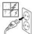
| Power Supply | AC100-240V~ 50/60Hz |
| Operating Temperature | 0 °C to 40 °C (32 °F to 104 °F) |
| Operating Humidity | 10% to 80%, non-condensing |
| VESA Mount | 600 x 400 mm, M8 screws |
| Key Features | MagicInfo, Video Wall (up to 15x15), MDC control, UHD COLOR, Auto Source Switching, Eco Sensor |
| Input Ports | DVI, HDMI (2), DisplayPort, RGB, Audio, RS232C, RJ45, USB |
| Output Ports | DP Loopout, Audio Out, RS232C Out |
| Remote Control | Infrared with IR stereo cable support |
| Cleaning Instructions | Disconnect power, wipe with soft dry cloth (microfiber). Do not spray liquids directly. |
| Safety Features | Auto power off, no-signal power off, temperature control, safety lock |
| User Serviceable Parts | None. Refer all servicing to qualified personnel. |
| Warranty Information | Administration fee may apply if defect is not found after reading manual. Refer to manual for details. |
Frequently Asked Questions - LH55UHFHLBB SAMSUNG
User questions about LH55UHFHLBB SAMSUNG
0 question about this device. Answer the ones you know or ask your own.
Ask a new question about this device
Download the instructions for your Video Conferencing System in PDF format for free! Find your manual LH55UHFHLBB - SAMSUNG and take your electronic device back in hand. On this page are published all the documents necessary for the use of your device. LH55UHFHLBB by SAMSUNG.
USER MANUAL LH55UHFHLBB SAMSUNG
The colour and the appearance may differ depending on the product, and the content in the manual is subject to change without prior notice to improve the performance.
An administration fee may be charged in the following situations:
(a) An engineer is called out at your request, but it is found that the product has no defect (i.e., where the user manual has not been read).
(b) You bring the unit to a repair centre, but it is found that the product has no defect (i.e., where the user manual has not been read).
You will be informed of the administration fee amount before a technician visits.
© Samsung
Samsung owns the copyright for this manual. Use or reproduction of this manual in parts or entirety without the authorization of Samsung is prohibited. Trademarks other than Samsung are property of their respective owners.
Table of contents
Before Using the Product
| Safety Precautions 5 | |
| Safety symbols 5 | |
| Electricity and Safety 6 | |
| Installation | 7 |
| Operation | 9 |
| Precautions when handling the panel 11 | |
| Cleaning | 12 |
Storage and Maintenance 12
Preparations
| Checking the Components 13 | |
| Components | 13 |
| Parts | 14 |
| Reverse Side 14 | |
| Remote Control 15 | |
| Connection Using an IR Stereo Cable (sold separately) | 17 |
| Before Installing the Product (Installation Guide) | 18 |
| Switching between portrait and landscape | 18 |
| Ventilation | 18 |
Installing the Wall Mount 19
Preparing before installing Wall-Mount 19
Installing the Wall Mount 19
Wall Mount Kit Specifications (VESA) 20
| Remote Control (RS232C) 21 | |
| Cable Connection | 21 |
| Connection | 24 |
| Control Codes | 25 |
Connecting and Using a Source Device
| Before Connecting | 34 |
| Pre-connection Checkpoints | 34 |
| Connecting to a PC 34 | |
| Connection using the D-SUB cable (Analogue type) | 34 |
| Connection using a DVI cable (Digital type) | 35 |
| Connection Using an HDMI-DVI Cable 35 | |
| Connection Using an HDMI Cable | 36 |
| Connection Using an DP Cable | 36 |
| Connecting to a Video Device | 37 |
| Connection Using an HDMI-DVI Cable 37 | |
| Connection Using an HDMI Cable | 38 |
| Connecting to an Audio System | 38 |
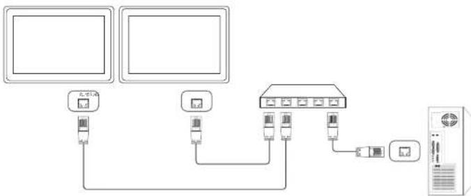
| Connecting the LAN Cable | 39 |
| Connecting the Network box (Sold separately) | 40 |
| MagicInfo | 40 |
| Changing the Input source 42 | |
| Source | 42 |
Using MDC
| MDC Programme | |
| Installation/Uninstallation | 43 |
| Installation | 43 |
| Uninstallation | 43 |
| Connecting to MDC 44 | |
| Using MDC via RS-232C (serial data communications standards) | 44 |
| Using MDC via Ethernet | 45 |
Home feature
| Video Wall | 47 |
| Video Wall | 47 |
| Horizontal x Vertical | 47 |
| Screen Position | 48 |
| Format | 48 |
| Picture Mode | 49 |
| On/Off Timer | 50 |
| On Timer | 50 |
| Off Timer | 50 |
| Holiday Management | 51 |
| Network Settings | 52 |
| MagicInfo Player I | 53 |
| ID Settings | 54 |
| ID Settings | 54 |
| Device ID Auto Set | 54 |
Table of contents
| PC Connection Cable | 54 |
| More settings | 55 |
Screen Adjustment
| Picture Mode | 56 |
| Backlight / Brightness / Contrast / Sharpness / Color / Tint (G/R) | 57 |
| Color Temperature | 57 |
| White Balance | 57 |
| Gamma | 57 |
| Calibrated Value | 57 |
| Picture Options | 58 |
| Color Tone | 58 |
| HDMI Black Level | 58 |
| Dynamic Backlight | 58 |
| UHD COLOR | 58 |
| Picture Size | 59 |
| Picture Size | 59 |
| Zoom/Position | 59 |
| Resolution | 59 |
| Auto Adjustment | 60 |
| PC Screen Adjustment | 60 |
| Picture Off | 60 |
| Reset Picture | 60 |
OnScreen Display
| Display Orientation | 61 |
| Onscreen Menu Orientation | 61 |
| Source Content Orientation | 61 |
| Aspect Ratio | 61 |
| Screen Protection | 62 |
| Pixel Shift | 62 |
| Timer | 62 |
| Immediate Display | 62 |
| Side Gray | 62 |
| Message Display | 63 |
| Source Info | 63 |
| No Signal Message | 63 |
| MDC Message | 63 |
| Menu Language | 63 |
| Reset OnScreen Display | 63 |
System
| Setup | 64 |
| Time | 65 |
| Clock Set | 65 |
| DST | 65 |
| Sleep Timer | 65 |
| Power On Delay | 65 |
| MagicInfo I Source | 65 |
| Auto Source Switching | 66 |
| Auto Source Switching | 66 |
| Primary Source Recovery | 66 |
| Primary Source | 66 |
| Secondary Source | 66 |
| Power Control | 66 |
| Auto Power On | 66 |
| PC Module Power | 66 |
| Standby Control | 67 |
| Network Standby | 67 |
| Power Button | 67 |
| Eco Solution | 67 |
| Energy Saving | 67 |
| Eco Sensor | 67 |
| Screen Lamp Schedule | 68 |
| No Signal Power Off | 68 |
| Auto Power Off | 68 |
| Temperature Control | 68 |
| Change PIN | 68 |
| General | 69 |
| Security | 69 |
| HDMI Hot Plug | 69 |
| Reset System | 69 |
Table of contents
Sound Adjustment
| HDMI Sound | 70 |
| Sound on Video Call | 70 |
| Reset Sound | 70 |
Support
| Software Update | 71 |
| Contact Samsung | 71 |
| Go to Home | 72 |
| Video Wall | 72 |
| Picture Mode | 72 |
| On/Off Timer | 72 |
| Network Settings | 72 |
| MagicInfo Player I | 72 |
| ID Settings | 72 |
| More settings | 72 |
| Reset All | 72 |
Troubleshooting Guide
| Requirements Before Contacting Samsung Customer Service Centre 73Testing the Product 73Checking the Resolution and Frequency 73Check the followings. 74 |
| Q & A 81 |
Specifications
| General | 82 |
| Preset Timing Modes 84 | |
Appendix
| Responsibility for the Pay Service (Cost to Customers) | 87 |
| Not a product defect 87 | |
| A Product damage caused by customer's fault | 87 |
| Others | 87 |
| Prevention of AfterImage Burn-In 88 | |
| What is afterImage burn-in? 88 | |
| Recommended prevention practices 88 | |
| Licence | 89 |
| Terminology | 90 |
Chapter 01
Before Using the Product
Safety Precautions
The following safety instructions are to ensure your personal safety and prevent property damage. Please read the following to ensure the proper use of the product.
Safety symbols
| Symbol | Name Meaning | |
 | Warning | A serious or fatal injury may result if instructions are not followed. |
 | Caution | Personal injury or damage to properties may result if instructions are not followed. |
 | Prohibition | Do NOT attempt. |
| [80D3] | Instruction | Follow directions. |
| CAUTION | |||
| RISK OF ELECTRIC SHOCK. DO NOT OPEN. | |||
| CAUTION: TO REDUCE THE RISK OF ELECTRIC SHOCK, DO NOT REMOVE COVER (OR BACK). THERE ARE NO USER SERVICEABLE PARTS INSIDE. REFER ALL SERVICING TO QUALIFIED PERSONNEL. | |||
| [DSW7] | This symbol indicates that high voltage is present inside. It is dangerous to make any kind of contact with any internal part of this product. |  | AC voltage: Rated voltage marked with this symbol is AC voltage. |
 | This symbol indicates that this product has included important literature concerning operation and maintenance. |  | DC voltage: Rated voltage marked with this symbol is DC voltage. |
 | Class II product: This symbol indicates that a safety connection to electrical earth (ground) is not required. |  | Caution. Consult instructions for use: This symbol instructs the user to consult the user manual for further safety related information. |
Electricity and Safety
The following images are for reference only. Real-life situations may differ from what is shown in the images.

Warning
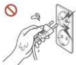
Do not touch the power plug with wet hands.
Otherwise, an electric shock may result.

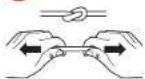
Do not bend or pull the power cable with force. Be careful not to leave the power cable under a heavy object.
Product failure, an electric shock or fire may result from a damaged cable.

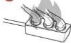
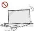
Do not connect multiple products to a single power socket.
Overheated power sockets may cause a fire.

Insert the power plug all the way in so it is not loose.
An unsecure connection may cause a fire.

Clean any dust around the pins of the power plug or the power socket with a dry cloth. A fire may result.

Connect the power plug to a grounded power socket. (Except for devices that do not provide grounding)
An electric shock or injury may result.

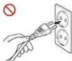
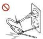
Do not use a damaged power plug or a loose power socket.
An electric shock or fire may result.
Caution
Hold the plug when disconnecting the power cable from the power socket.
An electric shock or fire may result.
When connecting the power plug to the port, be sure to connect it completely.
If the power plug is not completely connected to the port, the plug may be unexpectedly disconnected, or there is a risk of overheating due to overcurrent, leading to safety accidents.
Only use the power cable provided with your product by Samsung. Do not use the power cable with other products.
An electric shock or fire may result.
Keep the power socket where the power cord is connected unobstructed.
When a problem occurs with the product, the power cord must be unplugged to completely cut off power to the product. The power is not completely cut off by using only the Power button on the body of the product.
Do not disconnect the power cable while the product is being used.
The product may become damaged by an electric shock.
Installation

Warning
Before moving the product, turn off the power switch and disconnect the power cable and all other connected cables.
Damage to the cable may cause a fire or electric shock.
When Installing the product, keep it at a distance from the wall so that it is well ventilated.
An increased internal temperature may cause a fire.
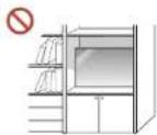
Do not install the product in a poorly ventilated space such as bookcase or closet.
An increased internal temperature may cause a fire.

Keep the plastic packaging out of the reach of children.
Children's misuse of the plastic packaging may cause suffocation.
Do not install the power cable (DC power supply) and the product near head sources.
(Candles, mosquito repellents, cigarettes, sprays, heating devices, places exposed to direct sunlight, and more)

When installing the product, fix it firmly so that it does not fall.
If the product is not fixed firmly and a child touches the product while playing, the product may fall, causing damage to the product or injury to the child.

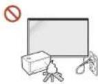
Do not install the product in a kitchen or near a kitchen counter.
Edible oil or oil vapor can damage or deform the product.
Have a technician Install the wall-mount hanger.
Installation by an unqualified person can result in an Injury. Only use approved cabinets.
If the product is installed in an unusual location, the surrounding environment may cause a serious quality problem. Therefore, be sure to contact Samsung Customer Service Centre before installation.
(Places where many fine dusts are generated, places where chemicals are used, places with too high or low temperatures, places with a lot of moisture or water, transportation equipment such as vehicles, airports and stations used continuously for a long time, and more)
Caution

When lifting and moving the product, do not touch the screen display, and make sure that at least two people work together.
The product may fall, causing personal injury or product damage.
Do not lay down the product on its front.
The screen may become damaged.
Prolonged exposure to direct sunlight may discolour the surface of the screen display.
Operation

Warning
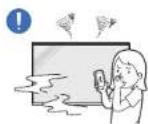
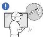
If the product generates a strange noise, a burning smell, or smoke, unplug the power plug immediately and contact your Samsung Customer Service Centre.
An electric shock or fire may result.
Keep the remote control batteries and the small accessories out of the reach of children. Ensure children do not swallow any of them.
If children have had the battery in their mouths, consult your doctor immediately.
If the product is dropped or its appearance is damaged, turn off the power switch and disconnect the power cord. Then contact Samsung Customer Service Centre.
Continued use can result in an electric shock or a fire.
Do not move the product by pulling the power cord or any cable.
Product failure, an electric shock or fire may result from a damaged cable.

Ensure the vents are not blocked by tablecloths or curtains.
An increased internal temperature may cause a fire.

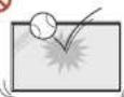


Do not apply an impact to the product.
• The screen display may be damaged.
• An electric shock or fire may result.
Do not insert metallic objects (chopsticks, coins, hairpins, etc) or objects that burn easily (paper, matches, etc) into the product (via the vent or input/output ports, etc).
- If foreign substances enter the product, be sure to power off the product and disconnect the power cord. Then contact Samsung Customer Service Centre,
• Product failure, an electric shock or fire may result.
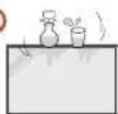
Do not place objects containing liquid (vases, pots, bottles, etc) or metallic objects on top of the product.
- If foreign substances such as water enter the product, be sure to disconnect the power cord. Then contact Samsung Customer Service Centre.
• Product failure, an electric shock or fire may result.
During a lightning or thunderstorm, power off the product and disconnect the power cord.
An electric shock or fire may result.
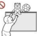
Do not leave heavy objects or items that children like (toys, sweets, etc.) on top of the product.
The product or heavy objects may fall as children try to reach for the toys or sweets resulting in a serious injury.
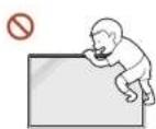
Do not hang on or climb on the product.
• The product may fall, causing personal injury or even death.
- Be especially careful that children do not hang on or climb on the product.
While the power plug is plugged into a power socket, do not insert a chopstick or other conductor into a remaining power socket. Also, after disconnecting the power plug from the power socket, do not touch the pins of the plug immediately.
Otherwise, an electric shock may result.

There is a high voltage inside the product. Never disassemble, repair or modify the product yourself.
- Contact Samsung Customer Service Centre for repairs.
• An electric shock or fire may result.
If a gas leakage is found, do not touch the product or the power plug, and ventilate the room immediately.
Sparks can cause an explosion or fire.
Do not use humidifiers or stoves around the product. An electric shock or fire may result.

Caution

Insert each battery so that its polarity (+, -) is correct.
If the polarity is not correct, the battery may rupture or the internal fluid may leak, causing contamination and damage to the surroundings, fire, or personal injury.

Do not place heavy objects on the product.
Product failure or personal injury may result.
When you do not use the product for a long time due to vacation or other reason, disconnect the power cord from the power socket.
Dust accumulation combined with heat can cause a fire, electric shock or electric leakage.
Use the product at the recommended resolution and frequency.
Your eyesight may deteriorate.
The batteries (and rechargeable batteries) are not ordinary refuse and must be returned for recycling purposes. The customer is responsible for returning the used or rechargeable batteries for recycling.
The customer can return used or rechargeable batteries to a nearby public recycling centre or to a store selling the same type of the battery or rechargeable battery.
Rest your eyes for more than 5 minutes for every 1 hour of product use.
Eye fatigue will be relieved.
Leaving the screen fixed on a stationary image for an extended period of time may cause afterimage burn-in or defective pixels.
When you do not use the product for a long time, activate power-saving mode or set the screen saver to moving-picture mode.
Do not use or keep combustible spray or an inflammable substance near the product. An explosion or fire may result.
Use only the specified standardised batteries, and do not use a new battery and a used battery at the same time.
Otherwise, the batteries may be damaged or cause fire, personal injury or damage due to a leakage of the internal liquid.
Do not watch the product screen too closely and continuously for a long time. Your eyesight may deteriorate.
Do not lift or move the product when it is in operation.
Do not touch the screen when the product has been turned on for an extended period of time as it will become hot.
When using headphones or earphones, do not turn the volume too high or use them for a long time.
Damage to your hearing may result.
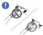
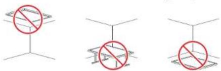
Precautions when handling the panel


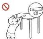
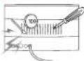
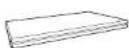
Do not stand the product as shown in the image. The panel is fragile and can get damaged.

Lay the product down to handle it as shown in the image. (the packaging can be used).

Ensure you use the handles on the back when moving the product.


Do not hold or grasp any area of the product within 15 mm from the front.
Cleaning
Warning
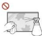
Do not spray water or cleaner directly on the product.
- The product's surface may be damaged, or the markings may be erased.
• An electric shock or fire may result.
Caution
When cleaning, be sure to disconnect the power plug and wipe gently with a soft and dry cloth such as superfine fibers or cotton flannels to prevent scratches.
The product's surface may be damaged, or the markings may be erased.
Be sure to use a soft and dry cloth such as superfine fibers or cotton flannels because the surface of the product and the screen display are vulnerable to scratches.
The product's surface or the screen display can be easily scratched with foreign substances.
Do not apply chemicals containing alcohol, solvent, or surfactant such as wax, benzene, thinner, pesticide, air freshener, lubricant, or cleaner to the product.
The product's exterior may be discoloured or cracked, the surface of the panel may be peeled off, or the markings may be erased.
Storage and Maintenance
Cleaning the exterior and display
Wipe the surface with a slightly wet, soft cloth, and then wipe with a dry cloth.

Precautions

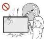
Do not scratch the screen with nails or sharp objects. Scratches may leave marks or damage the product.
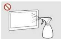
Do not spray water directly on any part of the product. Product failure, an electric shock or fire may result from water that enters the product
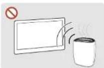
Due to the characteristics of high-glossy products, using a UV humidifier nearby may create white-coloured stains on the product.
- Removing a sticker attached on the screen may leave residues. Clean the residues before watching the screen.
- Do not strongly press and rub the product. Damage to the product may result.
- Do not wipe the screen with chemicals. Product failure may result.
- Contact Customer Service Centre if the inside of the product needs cleaning (service fee will be charged).
- We recommend wearing clean gloves when touching the front panel instead of bare hands.
Chapter 02 Preparations
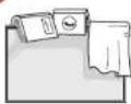
Checking the Components
- Contact the vendor where you purchased the product if any components are missing.
- The pictures may look different from the actual components.
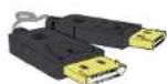
Components
Components may differ in different locations.
Quick Setup Guide

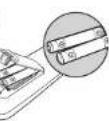
Batteries
(Not available in some locations)

Holder-Ring x 4 / Screw x 4
Warranty card
(Not available in some locations)
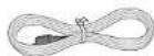
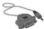
Remote Control DP cable RS232C(IN) adapter
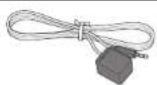
External IR cable
(Not available in some locations)
Regulatory guide Power cord
Parts
Reverse Side
The colour and shape of parts may differ from what is shown. Specifications are subject to change without notice to improve quality.
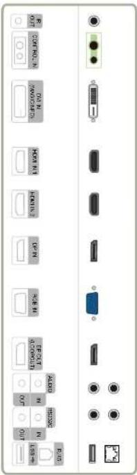
| IR OUT | Receives the remote control signal via the external sensor board and outputs the signal via LOOP OUT. |
| CONTROL IN | Supplies power to the external sensor board or receives the light sensor signal. |
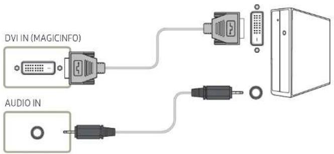
| DVI IN (MAGICINFO) | DVI IN: Connects to a source device using a DVI cable or HDMI-DVI cable.MAGICINFO: To use MagicInfo, make sure to connect the DP-DVI cable. |
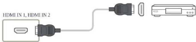
| HDMI IN 1, HDMI IN 2 | Connects to a source device using an HDMI cable. |
| DP IN | Connects to a PC using a DP cable. |
| RGB IN | Connects to a source device using a D-SUB cable. |
| DP OUT (LOOPOUT) | Connects to another product using a DP cable.When connecting monitors through DP Loopout, using the DP cable that came with the package is recommended.This port uses an algorithm that is specific to UHD resolution input and output. The port is not compatible with monitors that have FHD content-specific DP Loopout ports. Connecting Loopout ports between monitors of the same model is recommended. |
| AUDIO IN | Receives sound from a source device via an audio cable. |
| AUDIO OUT | Outputs sound to an audio device via an audio cable. |
| RS232C IN | Connects to MDC using an RS232C adapter. |
| RS232C OUT | |
| RJ45 | Connects to MDC using a LAN cable. (10/100 Mbps) |
| USB ↔ | Connect to a USB memory device. (Only for update purpose) |
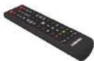
Remote Control
Using other display devices in the same space as the remote control of this product can cause the other display devices to be inadvertently controlled. A button without a description in the image below is not supported on the product.
natural_image
Line drawing of a remote control with buttons and dials (no text or symbols)- Remote control button functions may differ for different products.
Use the remote control within 7m to 10m from the sensor on the product at an angle of 30° from the left and right. - Store used batteries out of reach of children and recycle.
- Do not use a new and used battery together. Replace both batteries at the same time.
- Remove batteries when the remote control is not to be used for an extended period of time.
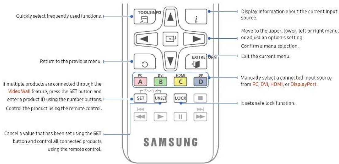
natural_image
Line drawing of a remote control with no text or symbols on the device itself- Remote control button functions may differ for different products.
Use the remote control within 7m to 10m from the sensor on the product at an angle of 30° from the left and right.
- Store used batteries out of reach of children and recycle.
- Do not use a new and used battery together. Replace both batteries at the same time.
- Remove batteries when the remote control is not to be used for an extended period of time.
To place batteries in the remote control

natural_image
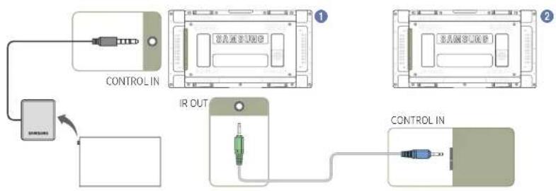
Four-panel diagram showing a cylindrical device with internal components and a separate view of its internal structure (no text or symbols)Connection Using an IR Stereo Cable (sold separately)
Make sure to connect the External IR cable while the product is powered off. Then, power on the product.
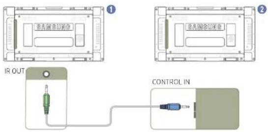
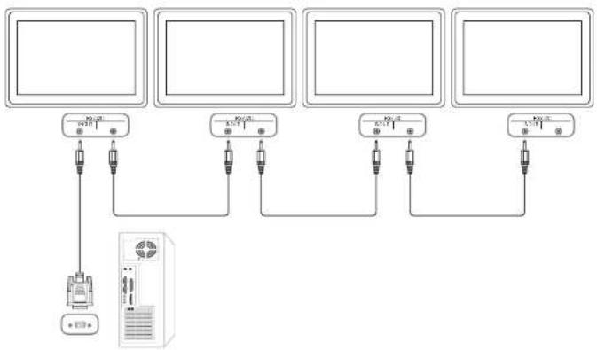
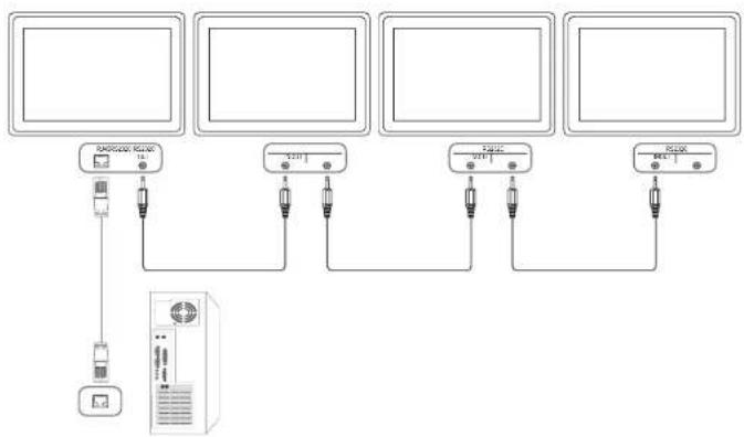
Controlling more than one display product using your remote control
- Connect the IR OUT port on the product to the CONTROL IN port on the other display product using the dedicated stereo cable.
- A command sent from the remote control pointed at product ^1 will be received by both display products ^1 and ^2 .
The appearance may differ depending on the product.
Controlling more than one display product using an External IR cable
- A command sent from the remote control pointed at product (to which the External IR cable is connected) will be received by both display products 1 and 2.
The appearance may differ depending on the product.
flowchart
graph TD
    A["CONTROL IN"] --> B["IR OUT"]
    B --> C["CONTROL IN"]
    style A fill:#f9f,stroke:#333
    style B fill:#ccf,stroke:#333
    style C fill:#cfc,stroke:#333
Before Installing the Product (Installation Guide)
To prevent injury, this apparatus must be securely attached to the floor/wall in accordance with the installation instructions.
- Ensure that an authorised installation company installs the wall mount.
- Otherwise, it may fall and cause personal injury.
- Make sure to install the specified wall mount.
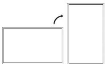
Switching between portrait and landscape
Contact Samsung Customer Service Centre for further details.
• To use the product in portrait orientation, rotate it clockwise.
natural_image
Simple geometric diagram showing a rectangle and a right square with an arrow indicating rotation (no text or symbols)Do not use this model installed on a ceiling, floor, or table.
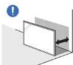
Ventilation
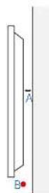
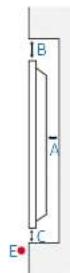
Installation on a Perpendicular Wall
A Minimum 40 mm
B Ambient temperature: Under 35°C
- When installing the product on a perpendicular wall, allow at least 40 mm of space between the product and wall surface for ventilation and ensure that the ambient A temperature is kept below 35°C.
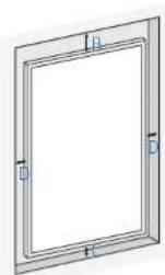
Installation on an Indented Wall
Contact Samsung Customer Service Centre for further details.
Plane view
A Minimum 40 mm
B Minimum 70 mm
C Minimum 50 mm
D Minimum 50 mm
E Ambient temperature: Under 35°C
When installing the product on an indented wall, allow at least the space specified above between the product and wall for ventilation and ensure that the ambient temperature is kept below 35°C.
Installing the Wall Mount
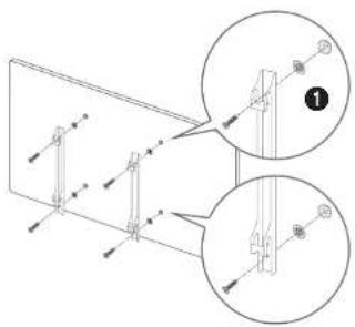
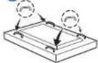
Preparing before installing Wall-Mount
To install a wall-mount from another manufacturer, use the Holder-Ring ^1 .
Installing the Wall Mount
The wall mount kit (sold separately) allows you to mount the product on the wall.
For detailed information on installing the wall mount, see the instructions provided with the wall mount.
We recommend you contact a technician for assistance when installing the wall mount bracket.
Samsung is not responsible for any damage to the product or injury to yourself or others if you select to install the wall mount on your own.
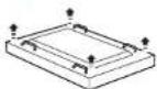
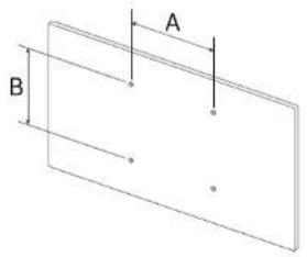
Wall Mount Kit Specifications (VESA)
Install your wall mount on a solid wall perpendicular to the floor. Before attaching the wall mount to surfaces other than plaster board, please contact your nearest dealer for additional information. If you install the product on a slanted wall, it may fall and result in severe personal injury.
- Samsung wall mount kits contain a detailed installation manual and all parts necessary for assembly are provided.
- Do not use screws that are longer than the standard length or do not comply with the VESA standard screw specifications. Screws that are too long may cause damage to the inside of the product.
- For wall mounts that do not comply with the VESA standard screw specifications, the length of the screws may differ depending on the wall mount specifications.
- Do not fasten the screws too firmly. This may damage the product or cause the product to fall, leading to personal injury. Samsung is not liable for these kinds of accidents.
- Samsung is not liable for product damage or personal injury when a non-VESA or non-specified wall mount is used or the consumer fails to follow the product installation instructions.
• Always have two people mount the product on a wall.
• Standard dimensions for wall mount kits are shown in the table below.
Unit: mm
VESA screw hole specs (A \* B) in millimetres Standard Screw Quantity
600×400 M8 4
Do not install your Wall Mount Kit while your product is turned on. It may result in personal injury due to electric shock.
Remote Control (RS232C)
Cable Connection
RS232C Cable
| Interface | RS232C (9 pins) |
| Pin | TxD (No.2), RxD (No.3), GND (No.5) |
| Bit rate | 9600 bps |
| Data bits | 8 bit |
| Parity | None |
| Stop bit | 1 bit |
| Flow control | None |
| Maximum length | 15 m (only shielded type) |
- Pin assignment
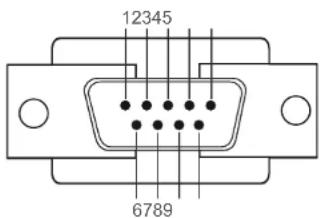
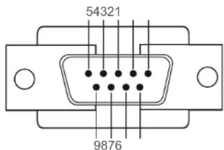
Pin Signal
| 1 | Detect data carrier |
| 2 | Received data |
| 3 | Transmitted data |
| 4 | Prepare data terminal |
| 5 | Signal ground |
| 6 | Prepare data set |
| 7 | Send request |
| 8 | Clear to send |
| 9 | Ring indicator |
- RS232C cable
Connector: 9-Pin D-Sub to Stereo Cable
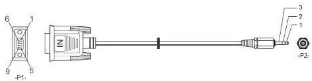
-P1--P1--P2--P2-
| Male type Rx | 3 | ---- | 1 | Tx | STEREO |
| Tx | 2 | ---- | 2 | Rx | PLUG |
| Gnd | 5 | ---- | 3 | Gnd | (3.5ø) |
LAN Cable
- Pin assignment
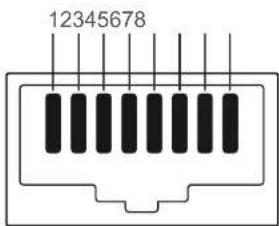
Pin No Standard Colour Signal
| 1 White and orange TX+ | ||
| 2 Orange TX- | ||
| 3 White and green | RX+ | |
| 4 Blue | NC | |
| 5 White and blue | NC | |
| 6 | Green | RX- |
| 7 | White and brown | NC |
| 8 Brown | NC | |
- Connector: RJ45
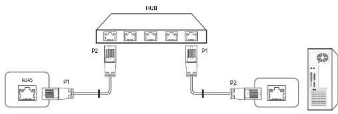
Direct LAN cable (PC to HUB)
flowchart
graph TD
    RJ45[" RJ45 "] --> P1[" P1 "]
    PJ[" PJ "] --> P1
    PJ --> P2[" P2 "]
    P1 --> HUB[" HUB "]
    P2 --> HUB
    HUB --> P1
    HUB --> P2
    style HUB fill:#f9f,stroke:#333
    style PJ fill:#ccf,stroke:#333
    style RJ45 fill:#cfc,stroke:#333
    style PJ fill:#fcc,stroke:#333
    style HUB fill:#ffc,stroke:#333
Signal P1 P2 Signal
TX+1<---->1 TX+
TX-2<---->2TX-
RX+3<---->3 RX+
RX-6<---->6 RX-
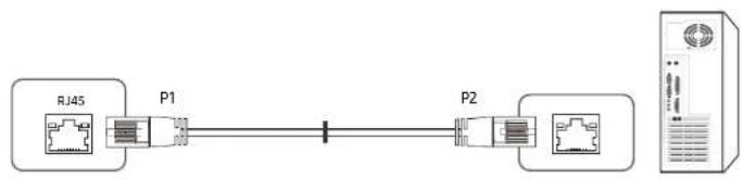
Cross LAN cable (PC to PC)
flowchart
graph LR
    RJ45["RJ45"] --> P1["P1"]
    P1 --> P2["P2"]
    P2 --> Server["Server"]
    style RJ45 fill:#f9f,stroke:#333
    style P1 fill:#ccf,stroke:#333
    style P2 fill:#cfc,stroke:#333
    style Server fill:#fcc,stroke:#333
Signal P1 P2 Signal
TX+1<---->3 RX+
TX-2<---->6 RX-
RX+3<---->1TX+
RX-6<---->2 TX-
Connection
Ensure you connect each of the adapters to the correct RS232C IN or OUT port on the product.
- Connection1
flowchart
graph TD
    A["Device 1"] --> B["Port E1"]
    C["Device 2"] --> D["Port E2"]
    E["Device 3"] --> F["Port E3"]
    G["Device 4"] --> H["Port E4"]
    I["Device 5"] --> J["Port E5"]
- Connection 2
flowchart
graph TD
    A["Monitor 1"] -->|USB interface| B["Server"]
    C["Monitor 2"] -->|USB interface| B
    D["Router"] -->|USB interface| B
    B --> E["Server"]
    style A fill:#f9f,stroke:#333
    style C fill:#f9f,stroke:#333
    style D fill:#f9f,stroke:#333
- Connection 3
flowchart
graph TD
    A["Device 1"] --> B["Audio Unit"]
    C["Device 2"] --> D["Audio Unit"]
    E["Device 3"] --> F["Audio Unit"]
    G["Device 4"] --> H["Audio Unit"]
    I["Device 5"] --> J["Audio Unit"]
    K["Device 6"] --> L["Audio Unit"]
    M["Device 7"] --> N["Audio Unit"]
    O["Device 8"] --> P["Audio Unit"]
    Q["Device 9"] --> R["Audio Unit"]
    S["Device 10"] --> T["Audio Unit"]
Control Codes
Viewing control state (Get control command)
| Header Command ID Data length Checksum | |
| 0xAA Command type | 0 |
Controlling (Set control command)
| Header Command ID Data length Data Checksum | |
| 0xAA Command type | 1 Value |
Command
No. Command type Command Value range
| 1 | Power control 0x11 0~1 | ||
| 2 | Volume control 0x12 0~100 | ||
| 3 | Input source control 0x14 | - | |
| 4 | Screen mode control | 0x18 | - |
| 5 | Screen size control | 0x19 | 0~255 |
| 6 | Auto adjustment control (PC and BNC only) | 0x3D | 0 |
| 7 | Video wall mode control | 0x5C | 0~1 |
| 8 | Safety Lock | 0x5D | 0~1 |
No. Command type Command Value range
| 9 | Video Wall On 0x84 | 0-1 | |
| 10 | Video Wall User Control | 0x89 | - |
- All communications take place in hexadecimals. The checksum is calculated by adding up all values except the header. If a checksum adds up to be more than 2 digits as shown below (11+FF+01+01=112), the first digit is removed.
E.g. Power On & ID=0
| Header | Command | ID | Data length | Data 1 | Checksum |
| 0xAA | 0x11 | 1 | "Power" | ||
| Header | Command | ID | Data length | Data 1 | 12 |
| 0xAA | 0x11 | 1 | 1 |
- To control all devices connected by a serial cable simultaneously irrespective of IDs, set the ID as "0xFE" and transmit commands. Commands will be executed by each device but ACK will not respond.
Power control
- Function
A product can be powered on and off using a PC.
• Viewing power state (Get Power ON / OFF Status)
Header Command ID Data length Checksum
0xAA 0x11 0
- Setting power ON/Off (Set Power ON / OFF)
Header Command ID Data length Data Checksum
0xAA 0x11 1 "Power"
"Power": Power code to be set on a product.
1: Power ON
0: Power OFF
- Ack
| Header | Command | ID | Data length | Ack/Nak | r-CMD | Val1 | Checksum |
| 0xAA | 0xFF | 3 | 'A' | 0x11 | "Power" |
"Power": Power code to be set on a product.
• Nak
| Header | Command | ID | Data length | Ack/Nak | r-CMD | Val1 | Checksum |
| 0xAA | 0xFF | 3 | 'N | 0x11 | 'ERR' |
"ERR": A code showing what error has occurred.
Volume control
- Function
The volume of a product can be adjusted using a PC.
• Viewing volume state (Get Volume Status)
| Header | Command | ID | Data length Checksum |
| 0xAA | 0x12 | 0 |
- Setting the volume (Set Volume)
| Header | Command | ID | Data length | Data | Checksum |
| 0xAA | 0x12 | 1 | "Volume" |
"Volume": Volume value code to be set on a product. (0-100)
- Ack
| Header | Command | ID | Data length | Ack/Nak | r-CMD | Val1 | Checksum |
| 0xAA | 0xFF | 3 | 'A' | 0x12 | "Volume" |
"Volume": Volume value code to be set on a product. (0-100)
• Nak
| Header | Command | ID | Data length | Ack/Nak | r-CMD | Val1 | Checksum |
| 0xAA | 0xFF | 3 | 'N' | 0x12 | "ERR" |
"ERR": A code showing what error has occurred.
Input source control
- Function
The input source of a product can be changed using a PC.
• Viewing Input source state (Get Input Source Status)
Header Command ID Data length Checksum
0xAA 0x14 0
- Setting the input source (Set Input Source)
Header Command ID Data length Data Checksum
0xAA 0x14 1 "Input Source"
"Input Source": An Input source code to be set on a product.
| 0x14 | PC |
| 0x18 | DVI |
| 0x0C | Input source |
| 0x08 | Component |
| 0x20 | MagicInfo |
| 0x1F | DVI_video |
| 0x30 | RF(TV) |
| 0x40 | DTV |
| 0x21 | HDMI1 |
| 0x22 | HDMI1_PC |
| 0x23 | HDMI2 |
| 0x24 | HDMI2_PC |
| 0x25 | DisplayPort |
DVI_video, HDMI1_PC and HDMI2_PC cannot be used with the Set command. They only respond to "Get" commands.
This model does not support HDMI1, HDMI1_PC, HDMI2 and HDMI2_PC ports.
— MagicInfo is only available with models that contain the MagicInfo function.
— RF(TV), DTV are only available with models that include a TV.
- Ack
| Header | Command | ID | Data length | Ack/Nak | r-CMD | Val1 | Checksum |
| 0xAA | 0xFF | 3 | 'A' | 0x14 | 'Input Source' |
"Input Source": An Input source code to be set on a product.
Nak
| Header | Command | ID | Data length | Ack/Nak | r-CMD | Val1 | Checksum |
| 0xAA | 0xFF | 3 | 'N' | 0x14 | "ERR" |
"ERR": A code showing what error has occurred.
Screen mode control
- Function
The screen mode of a product can be changed using a PC.
Screen mode cannot be controlled when the Video Wall function is enabled.
This control can only be used on models that include a TV.
• Viewing screen status (Get Screen Mode Status)
Header Command ID Data length Checksum
0xAA 0x18 0
- Setting the picture size (Set Picture Size)
Header Command ID Data length Data Checksum
| 0xAA | 0x18 | 1 "Screen Mode" |
| "Screen Mode": A code that sets the product status | ||
| 0x01 | 16:9 | |
| 0x04 | Zoom | |
| 0x31 | Wide Zoom | |
| 0x0B | 4:3 | |
- Ack
| Header | Command | ID | Data length | Ack/Nak | r-CMD | Val1 | Checksum |
| 0xAA | 0xFF | 3 | 'A' | 0x18 | "Screen Mode" |
"Screen Mode": A code that sets the product status
Nak
| Header | Command | ID | Data length | Ack/Nak | r-CMD | Val1 | Checksum |
| 0xAA | 0xFF | 3 | 'N' | 0x18 | "ERR" |
"ERR": A code showing what error has occurred
Screen size control
Function
The screen size of a product can be changed using a PC.
- Viewing the screen size (Get Screen Size Status)
| Header | Command ID | Data length Checksum |
| 0xAA | 0x19 | 0 |
- Ack
| Header | Command | ID | Data length | Ack/Nak | r-CMD | Val1 | Checksum |
| 0xAA | 0xFF | 3 | A' | 0x19 | "Screen Size" |
"Screen Size": product screen size (range: 0 - 255, unit: inch)
Nak
| Header | Command ID Data | length | Ack/Nak | r-CMD Val1 | Checksum | |
| 0xAA | 0xFF | 3 | 'N' | 0x19 | "ERR" | |
"ERR": A code showing what error has occurred
Auto adjustment control (PC and BNC only)
- Function
Automatically adjust the PC system screen using a PC.
• Viewing auto adjustment state (Get Auto Adjustment Status) None - Setting auto adjustment (Set Auto Adjustment)
Header Command ID Data length Data Checksum
| 0xAA 0x3D 1 "Auto | Adjustment* |
"Auto Adjustment": 0x00 (at all times)
- Ack
| Header Command ID Data | length | Ack/Nak r-CMD Val1 | Checksum | ||
| 0xAA | 0xFF | 3 | 'A' | 0x3D | "Auto Adjustment" |
| • Nak | |||||
| Header Command ID Data | length | Ack/Nak r-CMD Val1 | Checksum | ||
| 0xAA | 0xFF | 3 | 'A' | 0x3D | "ERR" |
"ERR": A code showing what error has occurred
Video Wall Mode Control
- Function
Video Wall mode can be activated on a product using a PC.
This control is only available on a product whose Video Wall is enabled.
• Viewing video wall mode (Get Video Wall Mode)
| Header Command ID Data length | Checksum | |
| 0xAA 0x5C | 0 | |
- Setting the video wall (Set Video Wall Mode)
| Header Command ID Data length | Data | Checksum | |
| 0xAA 0x5C | 1 | "Video Wall Mode" | |
"Video Wall Mode": A code used to activate Video Wall mode on a product
1: Full
0: Natural
- Ack
| Header Command | ID Data | length | Ack/Nak r-CMD | Val1 | Checksum | ||
| 0xAA | 0xFF | 3 | 'A' | 0x5C | "Video Wall Mode" | ||
"Video Wall Mode": A code used to activate Video Wall mode on a product
• Nak
| Header | Command ID Data | length | Ack/Nak r-CMD Val1 | Checksum | ||
| 0xAA | 0xFF | 3 | 'A' | 0x5C | "ERR" | |
"ERR": A code showing what error has occurred
Safety Lock
- Function
PC can be used to turn the Safety Lock function on or off on a product.
This control is available regardless of whether or not the power is turned on.
- Viewing the safety lock state (Get Safety Lock Status)
Header Command ID Data length Checksum
0xAA 0x5D 0
• Enabling or disabling safety lock (Set Safety Lock Enable / Disable)
Header Command ID Data length Data Checksum
0xAA 0x5D 1 *Safety
Lock*
*Safety Lock": Safety lock code to be set on a product
1:ON
0: OFF
- Ack
| Header Command ID Data | length | Ack/Nak r-CMD Val1 | Checksum | ||
| 0xAA | 0xFF | 3 | 'A' | 0x5D | "Safety Lock" |
"Safety Lock": Safety lock code to be set on a product
• Nak
| Header | Command | ID Data length | Ack/Nak r-CMD Val1 | Checksum | ||
| 0xAA | 0xFF | 3 | 'N' | 0x5D | "ERR" | |
"ERR": A code showing what error has occurred
Video Wall On
- Function
Turn Video Wall on or off on the product from your computer.
• Get Video Wall On/Off Status
Header Command ID Data length Checksum
0xAA 0x84
0
- Set Video Wall On/Off
Header Command ID Data length Data Checksum
0xAA 0x84
1 V.Wall_On
- V.Wall_On: Video Wall code to be assigned to the product
1: Video Wall ON
0: Video Wall OFF
(二)交易对方
| Header | Cuminum | IS | Data length | ACK/Nak | T-CMS | VAT | Checksum |
| 0xAA | 0xFF | 3 | 'A' | 0x84 | V.Wall_On |
V.Wall_On: Same as above
• Nak
| Header | Command | ID | Data length | Ack/Nak | r-CMD | Val1 | Checksum |
| 0xAA | 0xFF | 3 | 'N' | 0x84 | ERR |
"ERR": A code showing what error has occurred
Video Wall User Control
- Function
Turn the Video Wall function on or off on the product from your computer.
• Get Video Wall Status
Header Command ID Data length Checksum
0xAA 0x89 0
- Set Video Wall
Header Command ID Data length Val1 Val2 Checksum
0xAA 0x89
2
Wall_Div
Wall_SNo
Wall_Div: Video Wall Divider code assigned to the product
10x10 Video Wall Model
| 1234567891011121314 | 15 | ||||||||||||||
| Off | 0x00 0x00 0x00 0x00 0x00 0x00 0x00 0x00 0x00 0x00 0x00 0x00 0x00 | 0x00 | |||||||||||||
| 1 | 0x11 0x12 0x13 0x14 0x15 0x16 0x17 0x18 0x19 0x1A 0x1B 0x1C 0x1D 0x1E | 0x1F | |||||||||||||
| 2 | 0x21 0x22 0x23 0x24 0x25 0x26 0x27 0x28 0x29 0x2A 0x2B 0x2C 0x2D 0x2E | 0x2F | |||||||||||||
| 3 | 0x31 0x32 0x33 0x34 0x35 0x36 0x37 0x38 0x39 0x3A 0x3B 0x3C 0x3D 0x3E | 0x3F | |||||||||||||
| 4 | 0x41 0x42 0x43 0x44 0x45 0x46 0x47 0x48 0x49 0x4A 0x4B 0x4C 0x4D 0x4E | 0x4F | |||||||||||||
| 5 | 0x51 | 0x52 | 0x53 | 0x54 | 0x55 | 0x56 | 0x57 | 0x58 | 0x59 | 0x5A | 0x5B | 0x5C | 0x5D | 0x5E | 0x5F |
| 6 | 0x61 | 0x62 | 0x63 | 0x64 | 0x65 | 0x66 | 0x67 | 0x68 | 0x69 | 0x6A | 0x6B | 0x6C | 0x6D | 0x6E | 0x6F |
| 7 | 0x71 | 0x72 | 0x73 | 0x74 | 0x75 | 0x76 | 0x77 | 0x78 | 0x79 | 0x7A | 0x7B | 0x7C | 0x7D | 0x7E | N/A |
| 8 | 0x81 | 0x82 | 0x83 | 0x84 | 0x85 | 0x86 | 0x87 | 0x88 | 0x89 | 0x8A | 0x8B | 0x8C | N/A | N/A | N/A |
| 9 | 0x91 | 0x92 | 0x93 | 0x94 | 0x95 | 0x96 | 0x97 | 0x98 | 0x99 | 0x9A | 0x9B | N/A | N/A | N/A | N/A |
| 10 | 0xA1 | 0xA2 | 0xA3 | 0xA4 | 0xA5 | 0xA6 | 0xA7 | 0xA8 | 0xA9 | 0xAA | N/A | N/A | N/A | N/A | N/A |
| 11 | 0xB1 | 0xB2 | 0xB3 | 0xB4 | 0xB5 | 0xB6 | 0xB7 | 0xB8 | 0xB9 | N/A | N/A | N/A | N/A | N/A | N/A |
| 12 | 0xC1 | 0xC2 | 0xC3 | 0xC4 | 0xC5 | 0xC6 | 0xC7 | 0xC8 | N/A | N/A | N/A | N/A | N/A | N/A | N/A |
| 13 | 0xD1 | 0xD2 | 0xD3 | 0xD4 | 0xD5 | 0xD6 | 0xD7 | N/A | N/A | N/A | N/A | N/A | N/A | N/A | N/A |
| 14 | 0xE1 | 0xE2 | 0xE3 | 0xE4 | 0xE5 | 0xE6 | 0xE7 | N/A | N/A | N/A | N/A | N/A | N/A | N/A | N/A |
| 15 | 0xF1 | 0xF2 | 0xF3 | 0xF4 | 0xF5 | 0xF6 | N/A | N/A | N/A | N/A | N/A | N/A | N/A | N/A | N/A |
Wall_SNo: Product Number code assigned to the product
10x10 Video Wall Model : (1 \~ 100)
| Set Number Data |
| 1 0x01 |
| 2 0x02 |
| ... ... |
| 99 0x63 |
| 100 0x64 |
- Ack
| Header Command ID Data length Ack/Nak r-CMD Val1 Val2 Checksum | |||||||
| 0xAA | 0xFF | 4 | 'A' | 0x89 | Wall_Div | Wall_SNo | |
| • Nak | |||||||
| Header | Command | ID | Data length | Ack/Nak | r-CMD | Val1 | Checksum |
| 0xAA | 0xFF | 3 | 'N' | 0x89 | ERR | ||
"ERR": A code showing what error has occurred
Chapter 03
Connecting and Using a Source Device
Before Connecting
Pre-connection Checkpoints
Before connecting a source device, read the user manual provided with it.
The number and locations of ports on source devices may differ from device to device.
Do not connect the power cable until all connections are completed.
Connecting the power cable during connection may damage the product.
Connect the sound ports correctly: left = white and right = red.
Check the types of ports at the back of the product you want to connect.
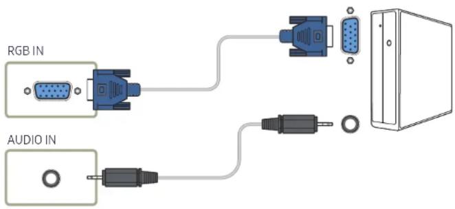
Connecting to a PC
- Do not connect the power cable before connecting all other cables. Ensure you connect a source device first before connecting the power cable.
- A PC can be connected to the product in a variety of ways. Select a connection method suitable for your PC.
Connecting parts may differ in different products.
Connection using the D-SUB cable (Analogue type)
Connection using a DVI cable (Digital type)
Connection Using an HDMI-DVI Cable
Connection Using an HDMI Cable
Connection Using an DP Cable
• Precautions for using DP
To increase the standby power capacity, the product stops DP communication when it is turned off or in power-saving mode.
If the product in dual monitor mode is turned off or goes into power-saving mode, monitor setting changes may not be updated. As a result, screen output may not be displayed properly.
Some graphics cards that are not compliant with the DP standard may prevent the Windows Booting/Bios screen from being displayed when the product is in power-saving mode. If this is the case, make sure to turn on the product first before turning on your PC.
The DisplayPort interface (DP IN) on the product and the provided DP cable are designed based on the VESA standards. Using a DP cable that is not VESA compliant may cause the product to function Improperly. Samsung shall not be held responsible for any issues from using a cable that is not VESA compliant.
Make sure to use a DP cable that is VESA compliant.
Connecting to a Video Device
- Do not connect the power cable before connecting all other cables. Ensure you connect a source device first before connecting the power cable.
• You can connect a video device to the product using a cable.
Connecting parts may differ in different products.
Press the SOURCE button on the remote control to change the source.
Connection Using an HDMI-DVI Cable
Audio will not be enabled if the product is connected to a video device using an HDMI-DVI cable. To resolve this, additionally connect an audio cable to the audio ports on the product and video device.
Supported resolutions include 1080p (50/60Hz), 720p (50/60Hz), 480p, and 576p.
Make sure to connect the same color connectors together. (white to white, red to red, etc.)
Connection Using an HDMI Cable
Using an HDMI cable or HDMI to DVI Cable (up to 1080p)
• For better picture and audio quality, connect to a digital device using an HDMI cable.
- An HDMI cable supports digital video and audio signals, and does not require an audio cable.
- To connect the product to a digital device that does not support HDMI output, use an HDMI-DVI and audio cables.
- The picture may not display normally (if at all) or the audio may not work if an external device that uses an older version of HDMI mode is connected to the product. If such a problem occurs, ask the manufacturer of the external device about the HDMI version and, if out of date, request an upgrade.
- Be sure to use an HDMI cable with a thickness of 14 mm or less.
- Be sure to purchase a certified HDMI cable. Otherwise, the picture may not display or a connection error may occur.
- A basic high-speed HDMI cable or one with ethernet is recommended. This product does not support the ethernet function via HDMI.
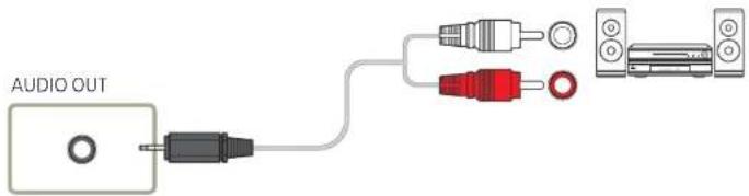
Connecting to an Audio System
Connecting parts may differ in different products.
Make sure to connect the same color connectors together. (white to white, red to red, etc.)
Connecting the LAN Cable
Connecting parts may differ in different products.
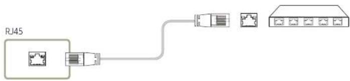
- Use Cat7(*STP Type) cable for the connection. *Shielded Twist Pair
Connecting the Network box (Sold separately)
For details on how to connect to a network box, refer to the user's manual provided with the network box upon purchase.
MagicInfo
To use MagicInfo, a network box (sold separately) must be connected to the product.
To change the Magicinfo settings, run "MagicinfoSetupWizard" on the desktop.
For details on how to use MagicInfo, refer to the DVD provided with the network box.
The information in this section is subject to change without notice for quality improvement.
If a problem occurs after installing an operating system other than the one provided with the network box, restoring the previous version of the operating system, or installing software that is not compatible with the operating system provided, you will not be able to benefit from technical support and will be charged a fee for a visit from a service technician. A product exchange or refund will also not be available.
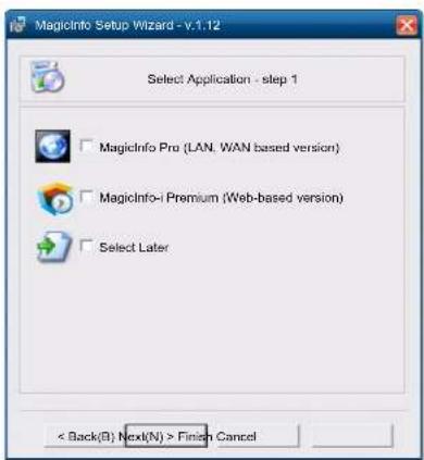
Entering MagicInfo mode
1 After installing and connecting the network box (sold separately) to the product, power on the product.
2 Press SOURCE on the remote control, and select MagicInfo.
Connecting the network box to the DVI IN (MAGICINFO) port on the product will change Source from DVI to MagicInfo.
3 Select the default application you want to run when MagicInfo starts.
4 Enter the IP information.
6 Select a display mode.
5 Select a language. (The default language is English.)
7 Double-check the settings you have just configured.
If the execution icon does not appear, double-click the MagicInfo icon on the desktop. The icon will appear at the bottom right of the screen.
Changing the Input source
Source
SOURCE → Source
– The displayed image may differ depending on the model.
Source allows you to select a variety of sources and change source device names.
You can display the screen of a source device connected to the product. Select a source from source list to display the screen of the selected source.
The input source can also be changed by using the SOURCE button on the remote control.
The screen may not display correctly if an incorrect source is selected for the source device you want to convert to.
Edit Name
SOURCE → Source → TOOLS → Edit Name → ENTER
Sometimes the screen will not display properly unless the name of a source device is specified in Edit Name.
In addition, It is best to rename the source device In Edit Name to obtain optimal picture quality.
The list can include the following source devices. Source devices on the list differ depending on the selected source.
VCR / DVD / Cable STB / HD STB / Satellite STB / AV Receiver / DVD Receiver / Game / Camcorder / DVD Combo / DHR / PC / DVI PC / DVI Devices
Available settings in the Picture menu depend on the current source and settings made in Edit Name.
- When connecting a PC to the HDMI IN 1, HDMI IN 2 port, set Edit Name to PC. In other cases, set Edit Name to AV devices.
- When connecting a PC to the HDMI IN 1, HDMI IN 2 port with HDMI cable, you should set the product to PC mode under Edit Name.
- When connecting a PC to the HDMI IN 1, HDMI IN 2 port with HDMI to DVI cable, you should set the product to DVI PC mode under Edit Name.
- When connecting an AV devices to the HDMI IN1, HDMI IN 2 port with HDMI to DVI cable, you should set the product to DVI Devices mode under Edit Name.
Chapter 04 Using MDC
Multiple display control "MDC" is an application that allows you to easily control multiple display devices simultaneously using a PC. For details on how to use the MDC programme, refer to Help after installing the programme. The MDC programme is available on the website.
After you press the On button following the Off button, the product checks its status for about a minute. To run a command, try it after a minute.
MDC Programme Installation/Uninstallation
Installation
MDC installation can be affected by the graphics card, mother board and network conditions.
1 Click the MDC Unified installation programme.
2 Select a language for installation. Next, click "OK".
3 When the "Welcome to the InstallShield Wizard for MDC_Unified" screen appears, click "Next".
4 In the "License Agreement" window displayed, select "I accept the terms in the license agreement" and click "Next".
5 In the displayed "Customer Information" window, fill out all the information fields and click "Next".
6 In the displayed "Destination Folder" window, select the directory path you want to install the programme in and click "Next".
If the directory path is not specified, the programme will be installed in the default directory path.
7 In the displayed "Ready to Install the Program" window, check the directory path to install the programme in and click "Install".
8 Installation progress will be displayed.
9 Click "Finish" in the displayed "InstallShield Wizard Complete" window.
Select "Launch MDC Unified" and click "Finish" to run the MDC programme immediately.
10 The MDC Unified shortcut icon will be created on the desktop after installation.
The MDC execution icon may not be displayed depending on the PC system or product specifications.
Press F5 if the execution icon is not displayed.
Uninstallation
1 Select Settings > Control Panel on the Start menu and double-click Add/Delete Program.
2 Select MDC Unified from the list and click Change/Remove.
Connecting to MDC
Using MDC via RS-232C (serial data communications standards)
An RS-232C serial cable must be connected to the serial ports on the PC and monitor.
flowchart
graph TD
    A["RS232C IN"] --> B["Computer"]
    C["RS232C OUT"] --> B
    D["RS232C IN"] --> E["Monitor 1"]
    F["RS232C OUT"] --> G["Monitor 2"]
    H["RS232C IN"] --> I["Monitor 2"]
    J["RS232C IN"] --> K["Monitor 2"]
Using MDC via Ethernet
Enter the IP for the primary display device and connect the device to the PC. Display devices can be connected to each other using a LAN cable.
Connection using a direct LAN cable
Multiple products can be connected using the RJ45 port on the product and the LAN ports on the HUB.
flowchart
graph TD
    RJ45["RI45"] --> HUB["HUB"]
    HUB --> Computer["Computer"]
    HUB --> Monitor1["Monitor 1"]
    HUB --> Monitor2["Monitor 2"]
Connection using a cross LAN cable
Multiple products can be connected using the RS232C IN / OUT port on the product.
flowchart
graph TD
    A["RJ45"] --> B["RS232C OUT"]
    B --> C["RS232C IN"]
    B --> D["RS232C OUT"]
    B --> E["RS232C IN"]
    C --> F["Monitor 1"]
    D --> G["Monitor 2"]
    E --> H["Computer"]
Chapter 05 Home feature
This feature is provided in Support → Go to Home. Accessible using the HOME button on the remote control.
Video Wall
HOME → Video Wall → ENTER

- The displayed image may differ depending on the model.
Customise the layout of multiple displays that are connected to form a video wall.
In addition, display part of a whole picture or repeat the same picture on each of the connected multiple displays.
To display multiple Images, refer to MDC Help or the MagicInfo user guide. Some models may not support the MagicInfo function.
Video Wall
You can activate or deactivate Video Wall.
To organise a video wall, select On.
- Off / On
Horizontal x Vertical
This feature automatically splits a videowall display based on a videowall matrix configuration.
Enter the videowall matrix.
The videowall display is split based on the configured matrix. The number of vertical or horizontal display devices can be set within the range 1 and 15.
A videowall display can be split into a maximum of 225 screens.
The Horizontal x Vertical option is only enabled when Video Wall is set to On.
Screen Position
To rearrange split screens, adjust the number for each product in the matrix using the Screen Position feature.
Selecting Screen Position will display the videowall matrix with the numbers assigned to the products that form the videowall.
To change the order of a display device, change the device number and press the button.
A maximum of 225 displays can be arranged In Screen Position.
The Screen Position option is only enabled when Video Wall is set to On.
To use the function, make sure Horizontal x Vertical is configured.
Format
Select how to display images on the videowall display.
• Full: Display images in full screen.
• Natural: Display images in the original aspect ratio.
The Format option is only enabled when Video Wall is set to On.
When using Video Wall mode, a resolution of 1280x720P, 1920x1080P or 3840x2160P is recommended.
Picture Mode
HOME → Picture Mode → ENTER

– The displayed image may differ depending on the model.
Select a picture mode (Picture Mode) suitable for the environment where the product will be used.
- Shop & Mall
Suitable for shopping malls.
- Select either Video/Image or Text depending on the picture mode.
- Office & School
Suitable for offices and schools.
- Select either Video/Image or Text depending on the picture mode.
- Terminal & Station
Suitable for bus terminals and train stations.
- Select either Video/Image or Text depending on the picture mode.
• Video Wall
Suitable for environments where videowall display are used.
- Select either Video/Image or Text depending on the picture mode.
- Calibration
In this mode, the brightness, colour, gamma and uniformity settings customised using the colour calibration programme Color Expert are applied.
- To use factory picture settings such as gamma, uniformity and white balance, set Picture Mode to Calibration.
- To additionally calibrate the picture, use Color Expert. You can adjust the picture quality settings (brightness, colour, gamma, uniformity) according to your preferences.
- To download the Color Expert programme, visit www.samsung.com/displaysolutions.
On/Off Timer
HOME → On/Off Timer → ENTER

– The displayed image may differ depending on the model.
You must set the clock before you can use Clock Set.
On Timer
Set On Timer so that your product turns on automatically at a time and on a day of your choosing.
The power is turned on with the specified volume or input source.
On Timer: Set the on timer by making a selection from one of the seven options. Ensure you set the current time first.
(On Timer1 – On Timer 7)
- Setup: Select Off, Once, Everyday, Mon-Fri, Mon-Sat, Sat-Sun or Manual. If you select Manual, you can choose the days you want On Timer to turn on your product. – The check mark indicates days you've selected.
- Time: Set the hour and minute. Use the number buttons or the up and down arrow keys to enter numbers. Use the left and right arrow buttons to change entry fields.
• Volume: Set the desired volume level. Use the left and right arrow buttons to change the volume level.
• Source: Select the input source of your choice.
Off Timer
Set the off timer (Off Timer) by making a selection from one of the seven options. (Off Timer1 - Off Timer7)
- Setup: Select Off, Once, Everyday, Mon\~Fri, Mon\~Sat, Sat\~Sun or Manual. If you select Manual, you can choose the days you want Off Timer to turn off your product.
- The check mark indicates days you've selected.
- Time: Set the hour and minute. Use the number buttons or the up and down arrow keys to enter numbers. Use the left and right arrow buttons to change entry fields.
Holiday Management
Timer will be disabled during a period specified as a holiday.
- Add Holiday: Specify the period you want to add as a holiday.
Select the start and end dates of the holiday you want to add using the ▲/▼ buttons, and click the Save button.
The period will be added to the list of holidays.
- Start: Set the start date of the holiday.
- End: Set the end date of the holiday.
Edit: Select a holiday item and then change the date.
Delete: Delete selected items from the list of holidays.
- Set Applied Timer: Set the On Timer and Off Timer to not activate on public holidays.
- Press ☐ to select the On Timer and Off Timer settings you do not want to activate.
- The selected On Timer and Off Timer will not activate.
Network Settings
HOME → Network Settings→ ENTER

– The displayed image may differ depending on the model.
View the network settings.
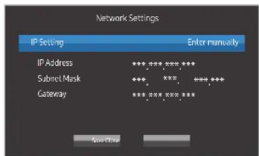
• IP Setting: Obtain automatically, Enter manually
• IP Address: Manually enter the IP Address if IP Setting is set to Enter manually.
- Subnet Mask: Manually enter the Subnet Mask if IP Setting is set to Enter manually.
• Gateway: Manually enter the Gateway if IP Setting is set to Enter manually.
MagicInfo Player I
HOME → MagicInfo Player I → ENTER

– The displayed image may differ depending on the model.
Change source to MagicInfo Player I.
MagicInfo Player I publishes and plays a variety of content, including created content and multimedia content (Images, videos and audio content), from the server or a connected device.
ID Settings
HOME → ID Settings → ENTER

– The displayed image may differ depending on the model.
Assign an ID to a set.
Press ▲/▼ to select a number, and press ↗.
ID Settings
Enter the ID number of the product connected to the input cable for input signal reception. (Range: 0\~224)
Enter the number you want using the number buttons on the remote control.
Device ID Auto Set
Assign ID number automatically for all connected products.
PC Connection Cable
Select a method to connect to MDC to receive the MDC signal.
- RS232C cable
Communicate with MDC via the RS232C-stereo cable. - RJ45(LAN) cable
Communicate with MDC via the RJ45 cable.
More settings
HOME → More settings → ENTER

The picture settings menu appears.
– The displayed image may differ depending on the model.
Chapter 06 Screen Adjustment
Configure the Picture settings (Backlight, Color Tone, etc.).
The layout of the Picture menu options may vary depending on the product.
- The displayed Image may differ depending on the model.
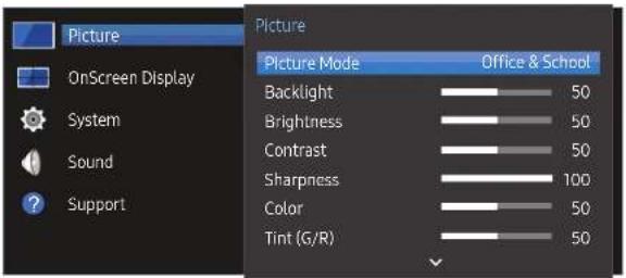
Picture Mode
MENU → Picture → Picture Mode → ENTER
Select a picture mode (Picture Mode) suitable for the environment where the product will be used.
- Shop & Mall
Suitable for shopping malls.
- Select either Video/Image or Text depending on the picture mode.
• Office & School
Suitable for offices and schools.
- Select either Video/Image or Text depending on the picture mode.
- Terminal & Station
Suitable for bus terminals and train stations.
- Select either Video/Image or Text depending on the picture mode.
- Video Wall
Suitable for environments where videowall display are used.
- Select either Video/Image or Text depending on the picture mode.
- Calibration
In this mode, the brightness, colour, gamma and uniformity settings customised using the colour calibration programme Color Expert are applied.
- To use factory picture settings such as gamma, uniformity and white balance, set Picture Mode to Calibration.
- To additionally calibrate the picture, use Color Expert. You can adjust the picture quality settings (brightness, colour, gamma, uniformity) according to your preferences.
- To download the Color Expert programme, visit www.samsung.com/displaysolutions.
Backlight / Brightness / Contrast / Sharpness / Color / Tint (G/R)
MENU → Picture → ENTER
Your product has several options for adjusting picture quality.
Picture Mode Picture Mode settings Adjustable options
| Shop & Mall, Office & School, Terminal & Station, Video Wall | Video/Image | Backlight / Brightness / Contrast / Sharpness / Color / Tint (G/R) |
| Text | Backlight / Brightness / Contrast / Sharpness |
Calibration Backlight
When you make changes to Backlight, Brightness, Contrast, Sharpness, Color or Tint (G/R), the OSD will be adjusted accordingly.
You can adjust and store settings for each external device you have connected to an input on the product.
Lowering picture brightness reduces power consumption.
Color Temperature
MENU → Picture → Color Temperature → ENTER
Adjust the colour temperature. (Range: 2800K–16000K)
If Picture Mode is set to Calibration, Color Temperature is disabled.
White Balance
MENU → Picture → White Balance → ENTER
Adjust the colour temperature for a more natural picture.
• R-Gain / G-Gain / B-Gain: Adjust each colour's (red, green, blue) brightness.
- Reset: Suitable for environments where videowall display are used.
Gamma
MENU → Picture → Gamma → ENTER
Adjust the primary colour intensity.
If Picture Mode is set to Calibration, Gamma is disabled.
Calibrated Value
MENU → Picture → Calibrated Value → ENTER
Select whether to apply the brightness, colour, gamma and uniformity settings customised using the colour calibration programme Color Expert to the Information and Advertisement modes.
- Don't Apply / Apply
To download the Color Expert programme, visit www.samsung.com/displaysolutions. If Picture Mode is set to Calibration, Calibrated Value is disabled.
Picture Options
MENU → Picture → Picture Options → ENTER
Picture Mode Picture Mode settings Adjustable options
| Shop & Mall, Office & School, Terminal & Station, Video Wall | Video/Image | Color Tone / HDMI Black Level / Dynamic Backlight / UHD COLOR |
| Text | Color Tone / HDMI Black Level / Dynamic Backlight / UHD COLOR | |
| Calibration | Dynamic Backlight / UHD COLOR |
Color Tone
If Picture Mode Is set to Text.
• Off / Cool / Standard / Warm
If Picture Mode Is set to Video/Image.
• Off / Cool / Standard / Warm1 / Warm2
If Picture Mode is set to Calibration, Color Tone is disabled.
Settings can be adjusted and stored for each external device connected to an input on the product.
HDMI Black Level
Selects the black level on the screen to adjust the screen depth.
- Low / Normal
This option is not available if the input source is set to PC.
Dynamic Backlight
Automatically adjust the backlight to provide the best possible screen contrast under the current conditions.
- Off / On
The Dynamic Backlight is not available when the input source is set to PC while Video Wall Is On.
UHD COLOR
- HDMI1: Off / On
- HDMI2: Off / On
- DisplayPort : Off / On
To enable a UHD input source, set UHD COLOR to On.
If monitors are connected through Loopout when a UHD resolution is in use, set UHD COLOR to On on all monitors.
A maximum of 25 monitors can be connected through Loopout when using UHD resolution.
To use UHD COLOR mode over an HDMI cable, using an HDMI cable that is compatible with HDMI 2.0 is recommended. Make sure that the cable is shorter than 2m.
Switching UHD COLOR between On and Off takes some time.
If the HDMI/DP connector with UHD COLOR enabled is connected to a device that does not support UHD content, the device may not operate properly. Connect a device that supports UHD content.
Picture Size
MENU → Picture → Picture Size → ENTER
choose size and aspect ratio picture displayed on screen.
Picture Size
Different screen adjustment options are displayed depending on the current input source.
Available Picture Size options can vary depending on whether the Picture Mode is Video/Image or Text.
• 16:9: Sets the picture to 16:9 wide mode.
- Zoom1: Use for moderate magnification. Cuts off the top and sides.
• Zoom2: Use for a stronger magnification.
• Smart View1: Reduces the 16:9 picture by 50%.
Smart View1 is enabled only in HDMI1, HDMI2 mode.
• Smart View 2: Reduce the top and bottom margins of the 16:9 screen by 25%.
Smart View 2 is enabled only in HDMI1, HDMI2 mode.
- Wide: Enlarges the aspect ratio of the picture to fit the entire screen.
• 4:3: Sets the picture to basic (4:3) mode.
Do not set your product to 4:3 format for a long time.
The borders displayed on the left and right, or top and bottom of the screen may cause image retention (screen burn) which is not covered by the warranty.
- Screen Fit: Displays the full image without any cut-off when HDMI1, HDMI2 (720p / 1080l / 1080p) signals are inputted.
- Custom: Changes the resolution to suit the user's preferences.
• Original: Display images in the original picture quality.
Available ports may differ depending on the model.
Zoom/Position
Adjust the screen size and position.
This option can be configured if the input source supports 1080i or 1080p and the Picture Size is Custom.
This option is not supported when a PC is connected.
From the Zoom/Position screen, follow the steps below.
1 Press the ▼ button to select Zoom/Position. Press the ↩ button.
2 Select the Zoom or Position. Press the ↻ button.
3 Press the ▲/▼/◄/► button to move the picture.
4 Press the □ button.
If you want to reset the picture to its original position, select Reset in the Zoom/Position screen. The picture will be set to its default position.
Resolution
If the picture is not normal even when the resolution of the graphics card is one of the following, you can optimise the picture quality by selecting the same resolution for the product as the PC using this menu.
Available resolutions: Off / 1024 x 768 / 1280 x 768 / 1360 x 768 / 1366 x 768
Auto Adjustment
MENU → Picture → Auto Adjustment → ENTER
Available in PC mode only.
Adjust frequency values/positions and fine tune the settings automatically.
PC Screen Adjustment
MENU → Picture → PC Screen Adjustment → ENTER
Available in PC mode only.
- Coarse / Fine
Removes or reduces picture noise.
If the noise is not removed by Fine-tuning alone, use the Coarse function to adjust the frequency as best as possible (Coarse) and Fine-tune again. After the noise has been reduced, re-adjust the picture so that it is aligned with the Centre of screen.
- Position
To adjust the PC's screen position if it is not centred or does not fit the product screen.
Press the ▲ or ▼ button to adjust the Vertical Position. Press the ◀ or ▶ button to adjust the Horizontal Position.
- Image Reset
Resets the image to the default settings.
Picture Off
MENU → Picture → Picture Off → ENTER
Selecting Picture Off switches off the screen. The volume is not disabled.
To switch the screen on, press any button other than the volume button.
Reset Picture
MENU → Picture → Reset Picture → ENTER
Resets your current picture mode to its default settings.
Chapter 07 OnScreen Display
– The displayed image may differ depending on the model.
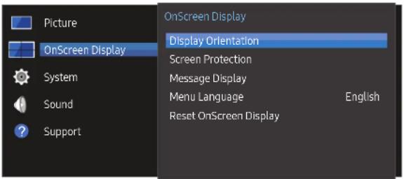
Display Orientation
MENU → OnScreen Display → Display Orientation → ENTER
Onscreen Menu Orientation
Set the menu screen orientation.
- Landscape: Display the menu in landscape mode (default).
- Portrait: Display the menu in portrait mode on the right side of the product screen.
Source Content Orientation
Set the orientation of content from external devices connected to the product.
- Landscape: Display the screen in landscape mode (default).
• Portrait: Display the screen in portrait mode.
Portrait orientation mode is not supported when a UHD resolution is in use.
Aspect Ratio
Set the rotated screen to be either full screen or original.
• Full Screen: Display the rotated screen in full screen.
• Original: Display the rotated screen in the original aspect ratio.
Available only when Source Content Orientation is set to Portrait.
Screen Protection
MENU → OnScreen Display → Screen Protection → ENTER
To reduce the possibility of screen burn, this unit is equipped with Pixel Shift screen burn prevention technology.
Pixel Shift moves the picture slightly on the screen.
The Pixel Shift time setting allows you to programme the time between movements of the picture in minutes.
Pixel Shift
Minimize image retention by finely moving pixels horizontally or vertically.
- Pixel Shift (Off / On)
Horizontal, Vertical and Time are enabled only when Pixel Shift is set to On.
• Horizontal: Sets how many pixels the screen moves horizontally.
• Vertical: Sets how many pixels the screen moves vertically. - Time: Set the time interval for performing the horizontal or vertical movement, respectively.
Available Pixel Shift Settings and Optimum Settings.
Available Settings Optimum Settings
| Horizontal (pixels) 0 ~ 4 4 | ||
| Vertical (pixels) 0 ~ 4 4 | ||
| Time (minute) | 1 min. ~ 4 min. | 4 min. |
The Pixel Shift value may differ depending on the model.
Displaying a still image or a 4:3 output for an extended period of time may cause Image retention. This is not a defect in the product.
Timer
You can set the timer for Screen Protection.
The Screen Protection feature stops automatically after a specified period of time.
• Timer (Off / Repeat / Interval)
-Off
- Repeat: Display the anti-burn in pattern at a specified interval.
- Interval: Display the anti-burn in pattern for a specified period of time (from the starting to finishing time).
When Clock Set is configured, Interval will be enabled.
Period, Start Time and End Time are enabled only when Timer is set to Repeat or Interval.
• Period: Specify the time interval to activate the Screen Protection function.
The option is enabled when Repeat is selected for Timer.
- Start Time: Set the start time to activate the screen protection function.
The option is enabled when Interval is selected for Timer.
• End Time: Set the end time to deactivate the screen protection function.
The option is enabled when Interval is selected for Timer.
Immediate Display
Select the screen saver you want to display immediately.
- Off / Fading Screen
Side Gray
When the screen is set to 4:3 aspect ratio, adjust the brightness of white margins on sides to protect the screen.
- Off / Light / Dark
Message Display
MENU 📄 → OnScreen Display → Message Display → ENTER
Source Info
Select whether to display the source OSD when the input source changes.
- Off / On
No Signal Message
Select whether to display the no-signal OSD when no signal is detected.
- Off / On
MDC Message
Select whether to display the MDC OSD when the product is controlled by the MDC.
- Off / On
Menu Language
MENU → OnScreen Display → Menu Language → ENTER
Set the menu language.
A change to the language setting will only be applied to the onscreen menu display. It will not be applied to other functions on your PC.
Reset OnScreen Display
MENU → OnScreen Display → Reset OnScreen Display → ENTER
This option returns the current settings under OnScreen Display to the default factory settings.
Chapter 08 System
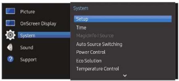
- The displayed image may differ depending on the model.
Setup
MENU → System → Setup → ENTER
Change the initial settings that were configured when you first used the product.
Press the ⏻ button.
1 Language
Select your language to start the on screen setup.
2 Picture Mode
If you set Picture Mode to Calibration, the video wall automatically has screen uniformity. Set the mode to Calibration. - Yes / No
3 Display Orientation
Configure the menu page orientation. - Landscape / Portrait
4 Network Settings
Set the IP settings, and then select Next.
5 Clock Set
Set the current date and time, and then select Next.
6 Complete
Congratulations! Setup is complete and you're ready to get started.
Time
MENU → System → Time → ENTER
You can configure Clock Set or Sleep Timer. Configure various time-related settings.
Press the INFO button if you want to view the current time.
Clock Set
Select Clock Set. Select Date or Time, and then press ↗.
Use the number buttons to enter numbers or press the up and down arrow buttons. Use the left and right arrow buttons to move from one entry field to the next. Press ☐ when done.
You can set the Date and Time directly by pressing the number buttons on the remote control.
DST
Switches the DST (Daylight Saving Time) function on or off.
Off / On
• Start Date: Set the start date of Daylight Saving Time.
• End Date: Set the end date of Daylight Saving Time.
• Time Offset: Select the correct time offset your timezone.
Sleep Timer
Automatically shuts off the product after a preset period of time.
Use the up and down arrows to select a period of time, and then press ↩. To cancel Sleep
Timer, select Off.
Power On Delay
When connecting multiple products, adjust the power-on time for each product to prevent power overload (within the range 0–50 seconds).
MagicInfo | Source
MENU → System → MagicInfo I Source → ENTER
The MagicInfo I Source feature is available if a network box (sold separately) is connected.
Pressing MagicInfo Player I on the remote control displays content connected to the network box (sold separately).
• DVI / DisplayPort
Auto Source Switching
MENU → System → Auto Source Switching → ENTER
Turning on the display with Auto Source Switching On, and the previous video source selection is not active, the display will automatically search the different video input sources for active video.
Auto Source Switching
When the Auto Source Switching is On, the display video source will automatically be searched for active video.
The Primary Source selection will be activated, if the current video source is not recognised.
Secondary Source selection will become active, if no primary video source is available.
If both the primary and secondary input sources are not recognised, the display will perform two searches for an active source, each search checking the primary and then secondary source. If both searches fail, the display will return to the first video source and display a message indicating that there is no signal.
When the Primary Source selection is set to All, the display will search all the video source inputs twice in sequence looking for an active video source, returning back to the first video source in the sequence if no video is found.
Primary Source Recovery
Select whether to restore the selected primary input source when a primary input source is connected.
The Primary Source Recovery function is disabled if Primary Source is set to All.
Primary Source
Specify Primary Source for the automatic input source.
Secondary Source
Specify Secondary Source for the automatic Input source.
Power Control
MENU → System → Power Control → ENTER
Auto Power On
This feature automatically turns on the product as soon as it is plugged in. Pressing the power button is not needed.
- Off / On
PC Module Power
The PC module can be turned on/off separately from the LFD.
Synced Power-On
To turn off the LFD without turning off the PC module, select Off.
- Off / On
Synced Power-Off
To turn on the PC module without turning on the LFD, select Off.
- Off / On
Standby Control
You can set the screen standby mode to be applied when an input signal is received.
• Auto
Power-saving mode will activate if no input signals are detected even though a source device is connected to the display.
The message No Signal will appear If no source device is connected.
- Off
The message No Signal will appear if no input signals are detected.
If No Signal is displayed although a source device is connected, check the cable connection.
If No Signal Message is set to Off, the No Signal message does not appear. If this is the case, set No Signal Message to On.
• On
Power-saving mode will activate if no input signals are detected.
Network Standby
This feature keeps the network power on when the product turns off.
- Off / On
Power Button
The power button can be set to either turn on the power or turn on/off the power.
• Power On Only: Set the power button to turn on the power.
• Power On/Off: Set the power button to turn on/off the power.
Eco Solution
MENU → System → Eco Solution → ENTER
Energy Saving
Reduce the power consumption by adjusting the screen brightness.
- Off / Low / Medium / High
Eco Sensor
To enhance your power savings, the picture settings will automatically adapt to the light in the room.
- Off / On
Adjusting the Backlight setting under Picture while Eco Sensor is on will disable the Off. If the screen contrast is not sufficient, set the Eco Sensor to Off. If the Eco Sensor is Off, it may not comply with energy standards.
This function may differ depending on the model.
Min. Backlight
When Eco Sensor is On, you can manually adjust the minimum screen brightness. Min. Backlight Is the darkest backlight mode. Make sure the Min. Backlight setting is lower than the Backlight setting.
If Eco Sensor is On, the display brightness may change (become slightly darker or brighter) depending on the surrounding light intensity.
Screen Lamp Schedule
The panel brightness is adjusted according to the Screen Lamp Schedule. A value closer to 100 makes the panel brighter.
This option is enabled when Clock Set is configured.
- Off / On
No Signal Power Off
Save power by turning the device off when no signal is received from any source.
• Off / 15 mln. / 30 mln. / 60 mln.
Disabled when an attached PC is in power saving mode.
The product will automatically power off at a specified time. The time can be changed as required.
Auto Power Off
The product will automatically turn off if you don't press a button on the remote or touch a button on product front panel within select hours to prevent overheating.
• Off / 4 hours / 6 hours / 8 hours
Temperature Control
MENU → System → Temperature Control → ENTER
This function detects the internal temperature of the product. You can specify the temperature range that is acceptable.
The default temperature is set to 77 °C.
Recommended temperature for Temperature Control is 75 °C \~ 80 °C (provided that the surrounding temperature is 40 °C).
The screen will become darker if the current temperature exceeds the specified temperature limit. If the temperature continues to rise, the product will power off to prevent overheating.
Change PIN
MENU → System → Change PIN → ENTER
The Change PIN screen will appear.
Choose any 4 digits for your PIN and enter it in Enter a new PIN.. Reenter the same 4 digits in Enter the PIN again..
When the Confirm screen disappears, press the Close button. The product has memorised your new PIN.
Default password: 0 - 0 - 0 - 0
Change the PIN to keep your device secure.
General
MENU → System → General → ENTER
Security
Enter your 4 digit PIN number. The default PIN number is "0-0-0-0".
If you want to change the PIN number, use the Enter PIN function.
Change the PIN to keep your device secure.
Safety Lock
It sets safe lock function.
- Off / On
All the menus and buttons of the product and remote control, except for the LOCK button on the remote control, will be locked by the Safety Lock function.
To unlock the menus and buttons, press the LOCK button and then enter the password (default password: 0 - 0 - 0 - 0).
Button Lock
This menu can be used to lock the buttons on the product.
Only the remote control can control the product if Button Lock is set to On.
- Off / On
HDMI Hot Plug
This feature is used to activate the time delay to turn on a DVI/HDMI source device.
- Off / On
Reset System
MENU → System → Reset System → ENTER
This option returns the current settings under system to the default factory settings.
Chapter 09 Sound Adjustment
Configure the sound (Sound) settings for the product.
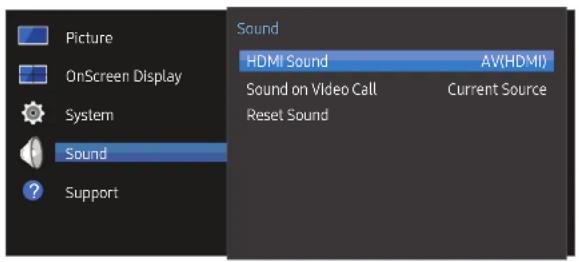
– The displayed image may differ depending on the model.
HDMI Sound
MENU → Sound → HDMI Sound → ENTER
Select whether to hear from AV(HDMI) or PC(DVI).
• AV(HDMI) / PC(DVI)
Sound on Video Call
MENU → Sound → Sound on Video Call → ENTER
Select sound output to listen to during a video call.
• Current Source / Video Call
Reset Sound
MENU ☐ → Sound → Reset Sound → ENTER
The displayed image may differ depending on the model. Reset all sound settings to the factory defaults.
Chapter 10 Support
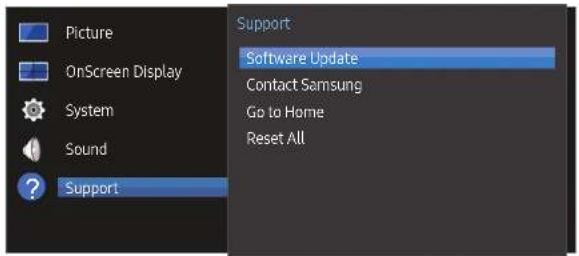
- The displayed image may differ depending on the model.
Software Update
MENU → Support → Software Update → ENTER
The Software Update menu lets you upgrade your product software to the latest version.
Be careful not to turn off the power until the upgrade is complete. The product will turn off and on automatically after completing the software upgrade.
When you upgrade software, all video and audio settings you have made will return to their default settings. We advise you to write down your settings so that you can easily reset them after the upgrade.
Contact Samsung
MENU → Support → Contact Samsung → ENTER
View this information when your product does not work properly or when you want to upgrade the software.
You can find information regarding our call centres and how to download products and software.
Contact Samsung and find the product Model Code and Software Version.
Go to Home
Accessible using the HOME button on the remote control.
MENU → Support → Go to Home → ENTER
Refer to the "Home feature" chapter for details on sub-menu items.
Go to Home to play a variety of content from a memory device or a connected network.
Video Wall
Customise the layout of multiple displays that are connected to form a video wall.
In addition, display part of a whole picture or repeat the same picture on each of the connected multiple displays.
To display multiple images, refer to MDC Help or the MagicInfo user guide. Some models may not support the MagicInfo function.
Picture Mode
Select a picture mode (Picture Mode) suitable for the environment where the product will be used.
On/Off Timer
You must set the clock before you can use On/Off Timer.
Set On Timer so that your product turns on automatically at a time and on a day of your choosing.
The power is turned on with the specified volume or input source.
Network Settings
View the network settings.
MagicInfo Player I
Change source to MagicInfo Player I.
MagicInfo Player I publishes and plays a variety of content, including created content and multimedia content (images, videos and audio content), from the server or a connected device.
ID Settings
Assign an ID to a set.
Press ▲/▼ to select a number, and press ↙.
More settings
The picture settings menu appears.
Reset All
MENU → Support → Reset All → ENTER
This option returns all the current settings for a display to the default factory settings.
Chapter 11 Troubleshooting Guide
Before calling Samsung Customer Service Centre, test your product as follows. If the problem persists, contact Samsung Customer Service Centre.
If the screen remains blank, check the PC system, video controller and cable.
Requirements Before Contacting Samsung Customer Service Centre
Testing the Product
Check if your product is operating normally by using the product test function.
If the screen remains blank while the power LED blinks even when the product is correctly connected to a PC, perform product testing.
1 Power off both the PC and product.
2 Disconnect all the cables from the product.
3 Power on the product.
4 If No Signal is displayed, the product is operating normally.
Checking the Resolution and Frequency
Not Optimum Mode will briefly be displayed if a mode that exceeds a supported resolution is selected (refer to Supported Resolutions).
Check the followings.
Installation issue (PC mode)
| The screen keeps switching on and off. | Check the cable connection between the product and PC, and ensure the connection is secure. |
| Blank spaces are found on all four sides of the screen when an HDMI or HDMI-DVI cable is connected to the product and PC. | The blank spaces found on the screen have nothing to do with the product. |
| Blank spaces on the screen are caused by the PC or graphics card. To resolve the problem, adjust the screen size in the HDMI or DVI settings for the graphics card. | |
| If the graphics card settings menu does not have an option to adjust the screen size, update the graphics card driver to the latest version.(Please contact the graphics card or computer manufacturer for further details about how to adjust the screen settings.) | |
| PC is shown in Source when a PC is not connected. | PC Is always shown in Source irrespective of whether or not a PC is connected. |
Screen issue
| The power LED is off. The screen will not switch on. | Make sure that the power cord is connected. |
| No Signal Is displayed on the screen. | Check that the product is connected correctly with a cable. |
| Check that the device connected to the product is powered on. | |
| Not Optimum Mode is displayed. | This message is displayed when a signal from the graphics card exceeds the product's maximum resolution and frequency. |
| Refer to the Standard Signal Mode Table and set the maximum resolution and frequency according to the product specifications. | |
| The Images on the screen look distorted. | Check the cable connection to the product. |
Screen issue
| The screen is not clear. The screen is blurry. | Adjust Coarse and Fine. |
| Remove any accessories (video extension cable, etc) and try again. | |
| Set the resolution and frequency to the recommended level. | |
| The screen appears unstable and shaky. | Check that the resolution and frequency of the PC and graphics card are set within a range compatible with the product. Then, change the screen settings if required by referring to the Additional Information on the product menu and the Standard Signal Mode Table. |
| There are shadows or ghost Images left on the screen. | |
| The screen is too bright. The screen is too dark. | Adjust Brightness and Contrast. |
| White does not really look white. | Go to Picture and adjust the White Balance settings. |
| There is no Image on the screen and the power LED blinks every 0.5 to 1 second. | The product is in power-saving mode. |
| Press any key on the keyboard or move the mouse to return to the previous screen. | |
| The product will turn off automatically. | Go to System and make sure Sleep Timer is set to Off. |
| If a PC is connected to the product, check the power status of the PC. | |
| Make sure the power cable is connected properly to the product and power outlet. | |
| If the signal from a connected device is not detected, the product automatically turns off after 10 to 15 minutes. | |
| Picture quality of the product is different from the dealer shop where it was purchased. | Use an HDMI cable to obtain high-definition (HD) picture quality. |
Screen issue
| The screen display does not look normal. | Encoded video content may cause the display to appear corrupted in scenes featuring fast moving objects such as in a sports event or action video. |
| Low signal level or low picture quality may cause the display to appear corrupted. This does not mean the product is defective. | |
| A cell phone within a distance of one-meter radius may cause static on analogue and digital products. | |
| The brightness and colour do not look normal. | Go to Picture and adjust the screen settings such as Picture Mode, Color, Brightness and Sharpness. |
| Go to System and adjust the Energy Saving settings. | |
| Reset the screen settings to the default settings. | |
| Broken lines are displayed on the edges of the screen. | If Picture Size is set to Screen Fit, change the setting to 16:9. |
| Lines (red, green or blue) are displayed on the screen. | These lines are displayed when there is a defect in DATA SOURCE DRIVER IC on the monitor. Contact a Samsung Service Centre to resolve the issue. |
| The display looks unstable and then freezes. | The screen may freeze when a resolution other than the recommended resolution is used or if the signal is not stable. To resolve the issue, change the PC resolution to the recommended resolution. |
Screen issue
| The screen cannot be displayed in full screen. | A scaled SD (4-3) content file can cause black bars on both sides of an HD channel screen. |
| A video with an aspect ratio different from the product can cause black bars at the top and bottom of the screen. | |
| Change the screen size setting to full screen on the product or source device. |
Sound issue
| There is no sound. | Check the connection of the audio cable or adjust the volume. |
| Check the volume. | |
| The volume is too low. | Adjust the volume. |
| If the volume is still low after turning it up to the maximum level, adjust the volume on your PC sound card or software programme. | |
| Video is available but there is no sound. | If an HDMI cable is connected, check the audio output settings on the PC. |
| If a source device is usedMake sure the audio cable is properly connected to the audio input port on the product.Check the audio output settings for the source device.(For example, if an HDMI cable is connected to the monitor, the audio setting for the cable box may need to be changed to HDMI.) | |
| If a DVI-HDMI cable is used, a separate audio cable is required. | |
| If the product has a headphone port, make sure nothing is connected to it. | |
| Reconnect the power cable to the device and then reboot the device. |
Sound issue
| There is static coming from the speakers. | Check the cable connection. Make sure a video cable is not connected to an audio input port. |
| Check the signal strength after connecting a cable. | |
| Low signal level can cause corrupted sound. | |
| There is audible sound when the volume is muted. | Adjust the volume for the external speakers. |
| Audio settings for main speakers are separate from the internal speakers on the product.Changing or muting the volume on the product does not affect an external amplifier(decoder). |
Remote control issue
| The remote control does not work. | Make sure that the batteries are correctly in place (+/-). |
| Check if the batteries are flat. | |
| Check for power failure. | |
| Make sure that the power cord is connected. | |
| Check for any special lighting or neon signs switched on in the vicinity. |
Source device issue
| A beeping sound is heard when my PC is booting. | If a beeping sound is heard when your PC is booting, have your PC serviced. |
Other issue
| The product smells like plastic. | The plastic smell is normal and disappears over time. | |
| The monitor appears tilted. | Remove and then attach the stand again to the product. | |
| Audio or video cuts out intermittently. | Check the cable connection and connect it again if required. | |
| Using a very hard or thick cable may corrupt audio and video files.Make sure cables are flexible enough to ensure durability. When mounting the product onto a wall, it is recommended to use right-angle cables. | ||
| Small particles are found on the edges of the product. | The particles are part of the product design. The product is not defective. | |
| When I try to change the PC resolution, a message "Mode not Supported" appears. | The message "Mode not Supported" appears if the input source resolution exceeds the maximum resolution of the display.To resolve the issue, change the PC resolution to a resolution supported on the display. | |
| There is no sound from the speakers in HDMI mode when a DVI-HDMI cable is connected. | DVI cables do not transmit sound data.Make sure to connect the audio cable to the correct input jack to enable audio. | |
| HDMI Black Level Is not functioning properly on an HDMI device with YCbCr output. | This function is available only when a source device, such as a DVD player and STB, is connected to the product via an HDMI (RGB signal) cable. | |
| There is no sound In HDMI mode. | Displayed picture colours may not look normal. Video or sound may not be available. This can occur if a source device that only supports an older version of the HDMI standard is connected to the product.If these issues occur, connect an audio cable along with the HDMI cable. | |
| Some PC graphics cards may not automatically recognise HDMI signals that do not include sound. In this case, manually select a sound input. | ||
| Sound input Screen mode | ||
| PC Auto PC settings | ||
| DVI PC Audio In (Stereo ports) | PC settings | |
Other issue
| HDMI-CEC does not work. | This product does not support the HDMI-CEC feature.To use several external devices compatible with the HDMI-CEC feature that are connected to the HDMI1 and HDMI2 ports on the product, turn off the HDMI-CEC features on all the external devices. External devices include Blu-ray and DVD players.Operating an external device when its HDMI-CEC feature is enabled may automatically stop other external devices.To change HDMI-CEC settings, refer to the device user guide or contact the device manufacturer for assistance. |
| The IR sensor is not functioning. | Make sure the sensor light turns on when a button is pressed on the remote control. |
| If the sensor light does not turn on, turn the power switch off and then on again on the back of the product.(The power LED lights up red when the screen is switched off.)If the sensor light still does not turn on after the power switch is turned off and then on again, an internal jack may be disconnected.Contact your nearest service centre to have the product serviced. | |
| If the sensor light that is on does not flash red when a button is pressed on the remote control, the IR sensor may be defective.Contact your nearest service centre to have the product serviced. | |
| This function is available only when a source device, such as a DVD player and STB, is connected to the product via an HDMI (RGB signal) cable. | |
| When booting the PC with the Input source set to DisplayPort the BIOS and booting screens do not appear. | Boot the PC when the set is turned on or when the input source is not DisplayPort. |
Q & A
Question Answer
| How can I change the frequency? | Set the frequency on your graphics card. Windows 7: Go to Control Panel → Appearance and Personalization → Display → Adjust resolution → Advanced Settings → Monitor and adjust the frequency in Monitor Settings. Windows 8: Go to Settings → Control Panel → Appearance and Personalization → Display → Adjust resolution → Advanced Settings → Monitor and adjust the frequency in Monitor Settings. Windows 10: Go to Settings → System → Display → Advanced display settings → Display adapter properties → Monitor, and adjust Screen refresh rate under Monitor settings. |
| How can I change the resolution? | Windows 7: Go to Control Panel → Appearance and Personalization → Display → Adjust Resolution and adjust the resolution. Windows 8: Go to Settings → Control Panel → Appearance and Personalization → Display → Adjust Resolution and adjust the resolution. Windows 10: Go to Settings → System → Display → Advanced display settings, and adjust the resolution. |
| How do I set powersaving mode? | Windows 7: Set power-saving mode in Control Panel → Appearance and Personalization → Personalize → Screen Saver Settings or BIOS SETUP on the PC. Windows 8: Set power-saving mode in Settings → Control Panel → Appearance and Personalization → Personalize → Screen Saver Settings or BIOS SETUP on the PC. Windows 10: Set power-saving mode in Settings → Personalization → Lock screen → Screen timeout settings → Power & sleep or BIOS SETUP on the PC. |
– Refer to the user manual for your PC or graphics card for further instructions on adjustment.
Chapter 12 Specifications
-Size
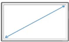
Display area
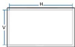
General
| Model Name | UD46E-A / UD46E-B / UD46E-C/UH46N-E / UM46N-E | UD55E-A / UD55E-B / UH55F-E/UM55H-E | |
| Panel Size | 46 CLASS (45.9 Inches / 116.8 cm) | 55 CLASS (54.6 inches / 138.7 cm) | |
| Display area | 1018.08 mm (H) x 572.67 mm (V) 1209.6 mm (H) x 680.4 mm (V) | ||
| Power Supply | AC100-240V~ 50/60HzRefer to the label at the back of the product as the standard voltage can vary in different countries. | ||
| Environmental considerations | Operating | Temperature: 0 °C - 40 °C (32 °F - 104 °F)* For installing the enclosure, keep the internal temperature at 40 °C or below.Humidity: 10 % - 80 %, non-condensing | |
| Storage | Temperature: -20 °C - 45 °C (-4 °F - 113 °F)Humidity: 5 % - 95 %, non-condensing | ||
- Plug-and-Play
This monitor can be installed and used with any Plug-and-Play compatible systems. Two-way data exchange between the monitor and PC system optimises the monitor settings. Monitor installation takes place automatically. However, you can customise the installation settings if desired.
- Due to the nature of the manufacturing of this product, approximately 1 pixel per million (1ppm) may appear brighter or darker on the panel. This does not affect product performance.
- This is a class A product. In a domestic environment this product may cause radio interference in which case the user may be required to take adequate measures.
• For detailed device specifications, visit the Samsung website.
• (Europe only)
To access the EPREL registration of the model: UD46E-A / UD46E-B / UD46E-C / UD55E-A / UD55E-B / UH46N-E / UM46N-E / UH55F-E / UM55H-E
(1) Go to https://eprel.ec.europa.eu
(2) Get the model identifier from the energy label of the product and type it in the search box
(3) Energy Labelling information of the model is shown
* You can directly access the product information via https://eprel.ec.europa.eu/qr/##### (registration no.)
The registration no. can be found on the rating label on your product.
• (Turkey only)
To access the energy labelling information of the model: UD46E-A / UD46E-B / UD46E-C / UD55E-A / UD55E-B / UH46N-E / UM46N-E / UH55F-E / UM55H-E
(1) Go to https://www.samsung.com/global/ecodesign_energy
(2) Get the model identifier from the energy label of the product and type it in the search box
(3) Energy labelling information can be found
Preset Timing Modes
This product can be set to only one resolution for each screen size to obtain the optimum picture quality due to the nature of the panel. Using a resolution other than the specified resolution may degrade the picture quality. To avoid this, it is recommended that you select the optimum resolution specified for your product.
Check the frequency when you exchange a CDT product (connected to a PC) for an LCD product. If the LCD product does not support 85 Hz, change the vertical frequency to 60 Hz using the CDT product before you exchange it with the LCD product.
- Horizontal Frequency
The time required to scan a single line from the left to the right side of the screen is called a horizontal cycle. The reciprocal number of a horizontal cycle is called horizontal frequency. Horizontal frequency is measured in kHz.
- Vertical Frequency
The product displays a single image multiple times per second (like a fluorescent light) to display what the viewer sees. The rate of a single image being displayed repeatedly per second is called vertical frequency or refresh rate. Vertical frequency is measured in Hz.
| Synchronization Horizontal Frequency | 30 - 81 kHz, 30 - 134 kHz (DisplayPort), 30 - 90 kHz (HDMI) |
| Vertical Frequency | 48 - 75 Hz, 56 - 75 Hz (DisplayPort), 24 - 75 Hz (HDMI) |
| Resolution Optimum resolution | 1920 x 1080 @ 60 Hz |
| Maximum resolution | 1920 x 1080 @ 60 Hz, 3840 x 2160 @ 60 Hz (HDMI1, HDMI2, DP) |
| Maximum Pixel Clock | 148.5 MHz (Analogue, Digital), 594 MHz (Displayport, HDMI) |
The screen will automatically be adjusted if a signal that belongs to the following standard signal modes is transmitted from your PC. If the signal transmitted from the PC does not belong to the standard signal modes, the screen may be blank with the power LED on. In such a case, change the settings according to the following table by referring to the graphics card user manual.
| Resolution Horizontal Frequency (kHz) | Vertical Frequency (Hz) | Pixel Clock (MHz) | Sync Polarity (H/V) | |
| IBM, 720 x 400 31.469 70.087 28.322 -/+ | ||||
| VESA/IBM, 640 x 480 31.469 59.940 25.175 -/- | ||||
| MAC, 640 x 480 35.000 66.667 30.240 -/- | ||||
| MAC, 832 x 624 | 49.726 | 74.551 | 57.284 | -/- |
| MAC, 1152 x 870 | 68.681 | 75.062 | 100.000 | -/- |
| VESA, 640 x 480 | 37.861 | 72.809 | 31.500 | -/- |
| VESA, 640 x 480 | 37.500 75.000 31.500 -/- | |||
| VESA, 800 x 600 | 37.879 | 60.317 | 40.000 | +/+ |
| VESA, 800 x 600 | 48.077 | 72.188 | 50.000 | +/+ |
| VESA, 800 x 600 | 46.875 | 75.000 | 49.500 | +/+ |
| VESA, 1024 x 768 | 48.363 | 60.004 65.000 -/- | ||
| VESA, 1024 x 768 | 56.476 | 70.069 | 75.000 | -/- |
| VESA, 1024 x 768 | 60.023 | 75.029 78.750 +/+ | ||
| VESA, 1152 x 864 | 67.500 | 75.000 | 108.000 | +/+ |
| VESA, 1280 x 720 | 45.000 60.000 | 74.250 +/+ | ||
| VESA, 1280 x 800 | 49.702 | 59.810 | 83.500 | -/+ |
| VESA, 1280 x 1024 | 63.981 | 60.020 | 108.000 | +/+ |
| VESA, 1280 x 1024 | 79.976 | 75.025 | 135.000 | +/+ |
| VESA, 1366 x 768 47.712 59.790 85.500 +/+ | ||||
| VESA, 1440 x 900 55.935 59.887 106.500 -/+ | ||||
| VESA, 1600 x 900 60.000 60.000 108.000 +/+ | ||||
| VESA, 1680 x 1050 | 65.290 | 59.954 | 146.250 | -/+ |
| VESA, 1920 x 1080 67.500 60.000 148.500 +/+ | ||||
| VESA, 2560 x 1440 | 88.787 | 59.951 | 241.500 | +/- |
| VESA, 3840 x 2160 | 133.313 | 59.997 | 533.250 | +/- |
| CEA, 3840 x 2160 | 67.500 | 30.000 | 297.000 | +/+ |
| CEA, 3840 x 2160 | 54.000 | 24.000 | 297.000 | +/+ |
| CEA, 3840 x 2160 | 56.250 | 25.000 | 297.000 | +/+ |
| CEA, 3840 x 2160 | 112.500 | 50.000 | 594.000 | +/+ |
Chapter 13 Appendix
Responsibility for the Pay Service (Cost to Customers)
When the service is requested, in spite of in warranty, we may charge you for a visit from a service technician in the following cases.
Not a product defect
Cleaning of the product, Adjustment, Explanation, Re-installation and etc.
- If a service technician gives instructions on how to use product or simply adjusts options without disassembling product.
- If a defect is caused by external environmental factors (Internet, Antenna, Wired Signal, etc.)
- If a product is reinstalled or devices are connected additionally after installing the purchased product for the first time.
• If a product is reinstalled to move to a different spot or to move to a different house. - If customer requests instructions on how to use because of another company's product.
- If customer requests instructions on how to use the network or another company's programme.
• If customer requests software installation and setup for the product.
• If a service technician removes/cleans dusts or foreign materials inside of the product. - If customer requests an installation additionally after purchasing a product through home-shopping or online.
A Product damage caused by customer's fault
Product damage caused by customer's mishandling or wrong repair
If a product damage is caused by;
• External impact or drop.
• Use of supplies or separately sold product unspecified by Samsung.
• Repair from a person besides an engineer of outsourcing service company or partner of Samsung Electronics Co., Ltd.
- Remodeling or repairing the product by customer.
• Using it with incorrect voltage or non-authorised electrical connections.
• Not following the "cautions" In User Manual.
Others
• If product fails by natural disaster. (lightning, fire, earthquake, flood damage, etc)
- If consumable components are all used up. (Battery, Toner, Fluorescent lights, Head, Vibrator, Lamp, Filter, Ribbon, etc.)
If customer requests a service in case the product has no defect, service fee may be charged. So please read User Manual first.
Prevention of Afterimage Burn-in
What is afterimage burn-in?
Afterimage burn-in should not occur when the panel is operating normally. Normal operation refers to a continuously changing video pattern. If the panel displays a fixed pattern for an extended period of time a slight voltage difference may occur between the electrodes in pixels that control the liquid crystals.
Such a voltage difference between electrodes increases with time and makes the liquid crystals thinner. When this occurs, a previous image can remain on the screen when the pattern changes.

This information is a guide to prevent afterimage burn-in. Viewing a fixed screen for an extended period of time may cause afterimage burn-in. This problem is not included in warranty.
Recommended prevention practices
Viewing a fixed screen for an extended period of time may cause afterimage burn-ins or smudges. If the product is not to be used for a long time, turn it off, or activate the Power Saving mode or Screen Saver with a moving image.
- Change the colours regularly.
Type 1 Type 2
- Avoid combinations of a text colour and background colour of contrasting brightness. Avoid using colours of contrasting brightness (black and white; grey and black).

The terms HDMI and HDMI High-Definition Multimedia Interface, and the HDMI Logo are trademarks or registered trademarks of HDMI Licensing LLC in the United States and other countries.
Terminology
480i / 480p / 720p / 1080i /
1080p____ Each of the scanning rates above refers to the number of effective scanning lines that decides the screen resolution. The scanning rate may be indicated in i (interlaced) or p (progressive), depending on the scanning method.
- Scanning
Scanning refers to a process of sending pixels that form an image progressively. A larger number of pixels will deliver a clearer and more vivid picture.
- Progressive
In progressive scan mode, all lines of pixels are scanned one by one (progressively) on the screen.
- Interlaced
In interlaced scan mode, every other line of pixels is scanned from top to bottom first and then the remaining lines of pixels (that were not scanned) are scanned.
Non-interlace Mode and Interlace Mode____. Non-interlace mode (progressive scan) displays a horizontal line from the top to the bottom of a screen progressively. Interlace mode displays the odd number lines first and the even number lines next. Non-Interlace mode is mainly used in monitors as it produces screen clarity and interlace mode is mainly used in TVs.
Dot Pitch____ The screen consist of red, green and blue dots. A shorter distance between the dots produces a higher resolution. Dot pitch refers to the distance between the shortest distance between dots of the same colour. Dot pitch is measured in millimetres.
Vertical Frequency ____ The product displays a single image many times per second (like a fluorescent light that flickers) to display an image for a viewer to see. The rate of a single image being displayed repeatedly per second is called vertical frequency or refresh rate. Vertical frequency is measured in Hz. E.g. 60Hz refers to a single image being displayed 60 times in one second.
Horizontal Frequency____ The time required to scan a single line from the left to the right side of the screen is called a horizontal cycle. The reciprocal number of a horizontal cycle is called horizontal frequency. Horizontal frequency is measured in kHz.
Source____ Input source refers to a video source device connected to the product such as a camcorder or video or DVD player.
Plug & Play____ Plug & Play is a function that allows the automatic exchange of information between a monitor and PC to produce an optimum display environment. The product uses VESA DDC (International standard) to execute Plug & Play.
Resolution____ Resolution is the number of horizontal dots (pixels) and vertical dots (pixels) that form a screen. It represents the level of display detail. A higher resolution enables more data to be displayed on the screen and is useful to perform multiple tasks simultaneously.
E.g. A resolution of 1920 X 1080 consists of 1,920 horizontal pixels (horizontal resolution) and 1,080 vertical pixels (vertical resolution).
DVD (Digital Versatile Disc)____ DVD refers to a CD-sized mass storage disk where you can save multimedia (audio, video or game) applications using MPEG-2 video compression technology.
HDMI (High Definition Multimedia Interface)____ It is an interface that can be connected to a digital audio source as well as a high-definition video source by using a single cable without compression.
Multiple Display Control (MDC)____ MDC (Multiple Display Control) is an application that allows multiple display devices to be controlled simultaneously using a PC. Communication between a PC and monitor takes place using RS232C (serial data transmission) and RJ45 (LAN) cables.