
725Ex - Security FLUKE - Free user manual and instructions
Find the device manual for free 725Ex FLUKE in PDF.


| Product Type | Intrinsically Safe Process Calibrator |
| Model | Fluke 725Ex |
| Category | Safety (Intrinsically Safe) |
| Dimensions (HxWxD) | Approx. 10.5 x 5.6 x 2.5 inches (26.7 x 14.2 x 6.4 cm) |
| Weight | Approx. 1.2 lbs (0.54 kg) including batteries |
| Power Supply | 4 x AA alkaline batteries or NiMH rechargeable |
| Battery Life | Typically 20 hours continuous use |
| Display | LCD with backlight, dual display for source and measure |
| Pressure Measurement | Internal sensor: ±30 psi (2 bar) differential; external pressure modules up to 10,000 psi |
| Temperature Measurement | RTD and thermocouple (types J, K, T, E, R, S, B, N, L, U) |
| Source Functions | Voltage (0-100 mV, 0-10 V), current (0-24 mA), resistance, frequency, pressure, temperature |
| Measure Functions | Voltage, current, resistance, frequency, pressure, temperature, continuity |
| Accuracy | ±0.02% of reading for DC voltage and current |
| Intrinsically Safe Certification | ATEX II 1 G Ex ia IIC T4, IECEx, CSA |
| Safety Class | Class I, Div 1, Groups A-D for hazardous locations |
| Operating Temperature | -10°C to 50°C (14°F to 122°F) |
| Storage Temperature | -20°C to 60°C (-4°F to 140°F) |
| IP Rating | IP54 (splash and dust resistant) |
| Cleaning | Wipe with a damp cloth and mild detergent; avoid solvents |
| Calibration | Recommended annually, traceable to NIST |
| Spare Parts | Battery cover, test leads, pressure module adapters |
| Warranty | 3 years standard |
Frequently Asked Questions - 725Ex FLUKE
User questions about 725Ex FLUKE
0 question about this device. Answer the ones you know or ask your own.
Ask a new question about this device
Download the instructions for your Security in PDF format for free! Find your manual 725Ex - FLUKE and take your electronic device back in hand. On this page are published all the documents necessary for the use of your device. 725Ex by FLUKE.
USER MANUAL 725Ex FLUKE
Multifunction Process Calibrator
Users Manual
January 2005 Rev. 3, 5/18
© 2005-2018 Fluke Corporation, All rights reserved. Specifications are subject to change without notice.
All product names are trademarks of their respective companies.
LIMITED WARRANTY AND LIMITATION OF LIABILITY
Each Fluke product is warranted to be free from defects in material and workmanship under normal use and service. The warranty period is three years and begins on the date of shipment. Parts, product repairs, and services are warranted for 90 days. This warranty extends only to the original buyer or end-user customer of a Fluke authorized reseller, and does not apply to fuses, disposable batteries, or to any product which, in Fluke's opinion, has been misused, altered, neglected, contaminated, or damaged by accident or abnormal conditions of operation or handling. Fluke warrants that software will operate substantially in accordance with its functional specifications for 90 days and that it has been properly recorded on non-defective media. Fluke does not warrant that software will be error free or operate without interruption.
Fluke authorized resellers shall extend this warranty on new and unused products to end-user customers only but have no authority to extend a greater or different warranty on behalf of Fluke. Warranty support is available only if product is purchased through a Fluke authorized sales outlet or Buyer has paid the applicable international price. Fluke reserves the right to invoice Buyer for importation costs of repair/replacement parts when product purchased in one country is submitted for repair in another country.
Fluke's warranty obligation is limited, at Fluke's option, to refund of the purchase price, free of charge repair, or replacement of a defective product which is returned to a Fluke authorized service center within the warranty period.
To obtain warranty service, contact your nearest Fluke authorized service center to obtain return authorization information, then send the product to that service center, with a description of the difficulty, postage and insurance prepaid (FOB Destination). Fluke assumes no risk for damage in transit. Following warranty repair, the product will be returned to Buyer, transportation prepaid (FOB Destination). If Fluke determines that failure was caused by neglect, misuse, contamination, alteration, accident, or abnormal condition of operation or handling, including overvoltage failures caused by use outside the product's specified rating, or normal wear and tear of mechanical components, Fluke will provide an estimate of repair costs and obtain authorization before commencing the work. Following repair, the product will be returned to the Buyer transportation prepaid and the Buyer will be billed for the repair and return transportation charges (FOB Shipping Point).
THIS WARRANTY IS BUYER'S SOLE AND EXCLUSIVE REMEDY AND IS IN LIEU OF ALL OTHER WARRANTIES, EXPRESS OR IMPLIED, INCLUDING BUT NOT LIMITED TO ANY IMPLIED WARRANTY OF MERCHANTABILITY OR FITNESS FOR A PARTICULAR PURPOSE. FLUKE SHALL NOT BE LIABLE FOR ANY SPECIAL, INDIRECT, INCIDENTAL, OR CONSEQUENTIAL DAMAGES OR LOSSES, INCLUDING LOSS OF DATA, ARISING FROM ANY CAUSE OR THEORY.
Since some countries or states do not allow limitation of the term of an implied warranty, or exclusion or limitation of incidental or consequential damages, the limitations and exclusions of this warranty may not apply to every buyer. If any provision of this Warranty is held invalid or unenforceable by a court or other decision-maker of competent jurisdiction, such holding will not affect the validity or enforceability of any other provision.
Fluke Corporation
P.O. Box 9090
Everett, WA 98206-9090
U.S.A.
Fluke Europe B.V.
P.O. Box 1186
5602 BD Eindhoven
The Netherlands
Table of Contents
Title Page
Introduction 1
Contact Fluke 1
Standard Equipment 3
Safety Information 3
Ex Hazardous Areas 3
Faults and Damage 9
Faults and Damage 9
Safety Regulations 9
Certification Information.... 10
Getting Acquainted with the Calibrator 10
Input and Output Terminals 10
Keys 12
Display.... 15
Getting Started 16
Shut Down Mode.... 16
Contrast Adjustment.... 18
Using Measure Mode 19
Measuring Electrical Parameters (Upper Display).... 19
Current Measurement with Loop Power.... 19
Measuring Electrical Parameters (Lower Display) 21
Measuring Temperature 22
Using Thermocouples 22
Using Resistance-Temperature Detectors (RTDs) 25
Measuring Pressure 28
Zeroing with Absolute Pressure Modules 29
Using Source Mode 31
Sourcing 4 to 20 mA.... 31
Simulating a 4- to 20-mA Transmitter.... 31
Sourcing Other Electrical Parameters 31
Simulating Thermocouples.... 34
Simulating RTDs 34
Source Pressure Mode 37
Setting 0 % and 100 % Output Parameters 39
Stepping and Ramping the Output 39
Manually Stepping the mA Output 39
Auto Ramping the Output 40
Storing and Recalling Setups 40
Calibrating a Transmitter 41
Calibrating a Pressure Transmitter 43
Calibrating an I/P Device 45
Switch Test 47
Testing an Output Device 48
Replacing the Batteries 49
Approved Batteries 50
Maintenance 50
Cleaning the Calibrator 50
Contents
(continued)
Service Center Calibration or Repair 51
Replacement Parts 51
Accessories 53
Specifications 55
DC Voltage Measurement 55
DC Voltage Source 55
Millivolt Measurement and Source* 55
DC mA Measurement and Source 56
Ohms Measurement 56
Ohms Source 56
Frequency Measurement.... 56
Frequency Source 57
Temperature, Thermocouples 57
Loop Power Supply 57
RTD Excitation (simulation) 58
Temperature, RTD Ranges, and Accuracies 58
Pressure Measurement 59
General Specifications.... 59
725Ex
Users Manual
Multifunction Process Calibrator
Introduction
⚠ Warning
Read "Safety Information" before using the Calibrator.
The Fluke 725Ex Multifunction Process Calibrator (hereafter referred to as "the Calibrator") is a handheld, battery-operated instrument that measures and sources electrical and physical parameters. For a summary of source and measurement functions, see Table 1.
In addition to the functions in Table 1, the Calibrator has the following features and functions:
- A split-screen display - The upper display allows the user to measure volts, current, and pressure only. The lower display allows the user to measure and source volts, current, pressure, resistance temperature detectors, thermocouples, frequency, and ohms.
- Calibrates a transmitter using the split-screen.
- A thermocouple (TC) input/output terminal and internal isothermal block with automatic reference junction temperature compensation.
- Stores and recalls setups.
- Manual stepping and automatic stepping and ramping.
Contact Fluke
To contact Fluke, call one of the following telephone numbers:
• Technical Support USA: 1-800-44-FLUKE (1-800-443-5853)
- Calibration/Repair USA: 1-888-99-FLUKE (1-888-993-5853)
• Canada: 1-800-36-FLUKE (1-800-363-5853)
• Europe: +31 402-675-200
• Japan: +81-3-6714-3114
• Singapore: +65-6799-5566
• China: +86-400-921-0835
• Anywhere in the world: +1-425-446-5500
Or, visit Fluke's website at www.fluke.com.
To register your product, visit http://register.fluke.com.
To view, print, or download the latest manual supplement, visit http://us.fluke.com/usen/support/manuals
Table 1. Summary of Source and Measure Functions
| Function Measure Source | ||
| dc V 0 V dc to 30 V dc | 0 V dc to 10 V dc | |
| dc mA 0 to 24 mA dc 0 | to 24 mA | |
| Frequency 1 CPM to 10 kHz | 1 CPM to 10 kHz | |
| Resistance | 0 Ω to 3200 Ω | 15 Ω to 3200 Ω |
| Thermocouple Types E | J, K, T, B, R, S, L, U, N, mV, XK, BP | |
| RTD (Resistance-Temperature Detector) | Ni120 Pt100 Ω (385) Pt100 Ω (3926) Pt100 Ω (3916) Pt200 Ω (385) Pt500 Ω (385) Pt1000 Ω (385) | |
| Pressure Fluke 750PE | x series modules ranging from 10 inH2O to 3000 psi | Fluke 750PEx series modules ranging from 10 inH2O to 3000 psi using an external pressure source (hand pump). |
| Other functions | Loop-Power Supply, Step, Ramp, Memory, Dual Display | |
Standard Equipment
The items listed below and shown in Figure 1 are included with the Calibrator. If the Calibrator is damaged or something is missing, contact the place of purchase immediately. To order replacement parts, see Replacement Parts in Table 9.
• TL75 test leads with caps (one set)
- Alligator clips (one set)
- Stackable alligator clip test leads (one set)
- Fluke 725Ex CCD
• Fluke 725Ex Safety Information
• 4 AA Batteries (installed)
• Hex Key, 5/64 in., short arm
Safety Information
A Warning statement identifies conditions and actions that pose a hazard(s) to the user. A Caution statement identifies conditions and actions that may damage the Calibrator or the equipment under test.
Symbols used on the Calibrator and in this manual, are explained in Table 2.
Ex Hazardous Areas
The Model 725Ex Calibrator has been designed for use in Ex Hazardous Areas. These are areas where potentially flammable or explosive vapors may occur. These areas are referred to as hazardous (classified) locations in the United States (NFPA 70 Article 500), as Hazardous Locations in Canada (CSA C22.1 Section 18), and as Explosive Gas Atmospheres by most of the rest of the world. The Model 725Ex calibrator is designed as intrinsically safe. This means that connecting the 725Ex calibrator to equipment that is used within intrinsically safe circuits will not cause an ignition capable arc as long as the entity parameters are suitably matched.
The Calibrator has two sets of parameters. The Vmax and Imax parameters show the maximum voltage and maximum current that may be connected to the Model 725Ex terminals without compromising the intrinsic safety. The voltage and current will generally come from intrinsic safety barriers that provide power to the field equipment such as transmitters and positioners (I/P devices). These barriers are identified with a maximum open circuit voltage parameter (Voc) and a maximum short circuit current parameter (Isc). The matching criterion requires that Voc of the barrier not exceed 30 V and Isc not exceed 100 mA.
The Calibrator will itself be a source of voltage and current. Each set of terminals has a Voc and an Isc rating as shown on the Calibrator CCD. When connecting
725Ex
Users Manual
terminals to other equipment, the Vmax and Imax ratings on the other equipment must exceed the Voc and Isc ratings for the terminals connected to on the 725Ex calibrator.
In addition to matching voltage and current entity parameters, it is also necessary to verify that capacitance and inductance has not been exceeded. Again, the Calibrator CCD identifies the maximum capacitance (Ca) and maximum inductance (La) that is permitted based either on the intrinsic safety barrier ratings or on the Calibrator ratings for the specific terminals used. As an example, the Calibrator CCD explains that the capacitance of each unit connected in the circuit (Ci) plus the capacitance of the cable in the circuit must not exceed the maximum allowed capacitance (Ca). Use a similar approach for inductance in the intrinsically safe circuit.
When connecting the Calibrator into a powered circuit, that is, when the circuit is powered by an intrinsic safety barrier, then the maximum circuit voltage used for the entity parameter evaluation will be the higher of either the Calibrator Voc or of the barrier Voc. The maximum current will be the sum of the Calibrator Isc and the barrier Isc. In this case, the maximum allowed inductance (La) will be reduced. This value will have to be determined using the ignition curves found in standards such as CSA C22.2 No. 157 or UL 913.
For additional information about Ex Hazardous Areas, refer to ANSI/ISA-12.01.01-2013 Definitions and
Information Pertaining to Electrical Instruments in Hazardous (Classified) Locations and to ANSI/ISA-RP12.06.01-2003 Recommended Practice for Wiring Methods for Hazardous (Classified) Locations Instrumentation Part 1: Intrinsic Safety.
⚠ Warning
To prevent fire, explosion, or personal injury:
- Use the Calibrator only as described in this User Manual and the Fluke 725Ex CCD (Concept Control Drawing) or the protection provided by the Calibrator may be impaired.
- Inspect the Calibrator before use. Do not use it if it appears damaged.
- Check the test leads for continuity, damaged insulation, or exposed metal. Replace damaged test leads.
- When using probes, keep fingers behind the finger guards on the probes.
• Never apply more than 30.0 V between the input terminals, or between any terminal and earth ground. - Applying more than 30.0 V to the input terminals invalidates the Calibrator's Ex Approval and may result in permanent damage to the Calibrator so it can no longer be used.
- Use the proper terminals, mode, and range for the measuring or sourcing application.
- To prevent damage to the device under test, be sure the Calibrator is in the correct mode before connecting the test leads.
- Never open the Calibrator case. Opening the case invalidates the Calibrator's Ex Approval.
- Make sure the battery door is closed and latched before entering an Ex hazardous area or using the Calibrator. See “Ex Hazardous Areas”.
- Remove the Calibrator from the Ex-hazardous area before opening the battery door. See "Ex Hazardous Areas".
- Remove test leads from the Calibrator before opening the battery door.
- When servicing the Calibrator, use only specified replacement parts. Do not open the Calibrator case. Opening the case invalidates the Calibrator's Ex Approval.
- Do not allow water inside the case.
- Do not operate the Calibrator around explosive dust.
- When using a pressure module, make sure the process pressure line is shut off and depressurized before connecting it or disconnecting it from the pressure module.
- Use four properly installed AA batteries to power the Calibrator.
• Use only the batteries listed in Table 8.
725Ex
Users Manual
- Disconnect test leads from the circuit under test before changing to another measure or source function.
- When measuring the pressure of toxic or flammable gases, care must be taken to minimize the possibility of leakage. Confirm that all pressure connections are properly sealed.
- Do not use in a damp or wet environment.
Caution
To avoid possible damage to Calibrator or to equipment under test:
- Disconnect the power and discharge all high-voltage capacitors before testing resistance or continuity.
• Use the proper jacks, function, and range for the measurement or sourcing application. - The MEASURE/SOURCE terminals on the Calibrator are sensitive to Electro-static discharge (ESD) at levels above ±2 kV. The Calibrator can experience temporary loss of measurement or source functionality. This can require you to restore product function, or cause permanent damage to the Calibrator. Usually, a disruptive ESD event occurs only when you connect the test leads to the circuits being measured or if you have a large static charge and touch the Calibrator terminals. The most common cause of ESD is a user that carries the Calibrator across a carpet, or other similar triboelectric activity, before they connect to the circuit being measured.
Mulitfunction Process Calibrator
Ex Hazardous Areas
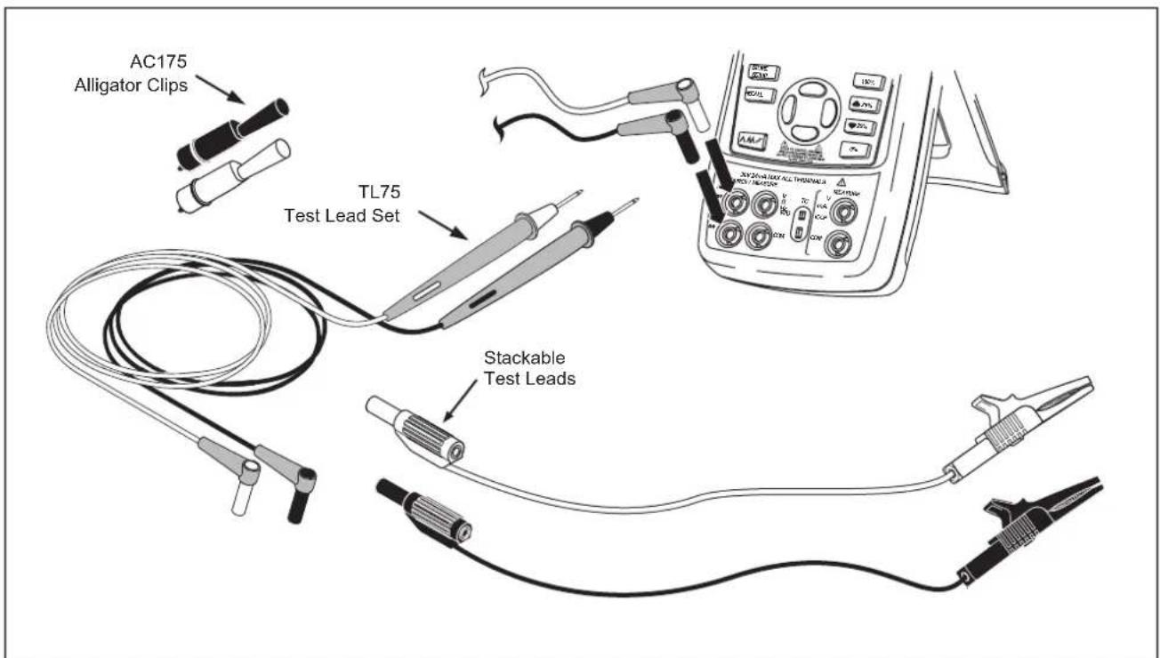
Figure 1. Standard Equipment
aly01f.eps
Table 2. Symbols
| Symbol | Meaning Symbol Meaning | ||
| ⚠️ | WARNING. RISK OF DANGER. |  | Consult user documentation. |
| 1 | Power ON/OFF |  | Double insulated |
| ⊥ | Earth ground |  | Pressure |
| + | Battery | [CAST] | Certified by CSA Group to North American safety standards. |
| --- | Direct current |  | Conforms to relevant Australian Safety and EMC standards. |
| ☒ | Conforms to relevant South Korean EMC Standards. | ||
| ☒ | This product complies with the WEEE Directive marking requirements. The affixed label indicates that you must not discard this electrical/electronic product in domestic household waste. Product Category: With reference to the equipment types in the WEEE Directive Annex I, this product is classed as category 9 "Monitoring and Control Instrumentation" product. Do not dispose of this product as unsorted municipal waste. | ||
Faults and Damage
Applying a voltage greater than 30 V to the input of the Calibrator invalidates its Ex Approval and may impair its safe operation in an Ex-hazardous area. See "Ex Hazardous Areas".
If there is any reason to suspect that the safe operation of the Calibrator has been affected, it must be immediately withdrawn from use, and precautionary measures must be taken to prevent any further use of the Calibrator in an Ex-hazardous area. See Ex Hazardous Areas.
Fully observe all instructions, warnings, and cautions contained in this manual. In case of doubt due to translation and/or printing errors, refer to the original English users manual.
The safety features and integrity of the Calibrator may be compromised by any of the following:
• External damage to the case
- Internal damage to the Calibrator
- Exposure to excessive loads
- Incorrect storage of the Calibrator
• Damage sustained in transit
• Certification markings are illegible
• Functioning errors occur
- Permitted limitations are exceeded
- Functioning errors or obvious measurement inaccuracies occur which prevent further measurement by the Calibrator
- Opening the case
Safety Regulations
The use of the Calibrator meets the requirements of the regulations providing that the user observes and applies the requirements as stated in the regulations and that improper and incorrect use of the Calibrator is avoided.
- Use must be restricted to the specified application parameters.
- Do not open the Calibrator.
- Do not remove or install the batteries within the Ex-hazardous area. See "Ex Hazardous Areas".
- Do not carry additional batteries within the Ex-hazardous area. See "Ex Hazardous Areas".
- Use only type tested batteries. The use of any other batteries will invalidate the Ex-certification and present a safety risk.
- Do not use the Calibrator in any circuit where the voltage or transients may exceed 30 V.
- Only use the Calibrator in circuits with compatible entity parameters. When the calibrator is used in an Ex hazardous area, unless the area is known to be safe, do not connect to any circuits that exceed the entity parameters defined on Fluke 725Ex CCD Control Drawing. See Ex Hazardous Areas.
725Ex
Users Manual
Certification Information
Class I Div. 1 Groups B, C, and D
Class I Zone 0 AEx/Ex ia IIB 171 °C
- Ta = -10 °C... +55 °C
• Manufactured by Fluke Corporation
6920 Seaway Blvd.
Everett, WA 98203, USA
Getting Acquainted with the Calibrator
Input and Output Terminals
Figure 2 shows the Calibrator input and output terminals. Table 3 explains their use.
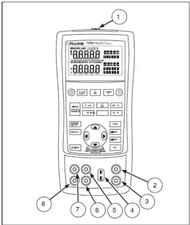
Figure 2. Input/Output Terminals and Connectors
Table 3. Input/Output Terminals and Connectors
| No Name | Description | |
| 1 | Pressure module connector | Connects the Calibrator to a pressure module. |
| 2,3 MEASURE V, mA terminals | Input terminals for measuring voltage, current, and supplying loop power. | |
| 4 | TC input/output | Terminal for measuring or simulating thermocouples. This terminal accepts a miniature polarized thermocouple plug with flat, inline blades spaced 7.9 mm (0.312 in) center to center. |
| 5,6 SOURCE/ MEASURE V, RTD, Hz, Ω terminals | Terminals for sourcing or measuring voltage, resistance, frequency, and RTDs. | |
| 7,8 SOURCE/ MEASURE mA terminals, 3W, 4W | Terminals for sourcing and measuring current, and performing 3W and 4W RTD measurements. | |
725Ex
Users Manual
Keys
Figure 3 shows the Calibrator keys and Table 4 explains their use.
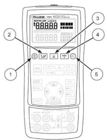
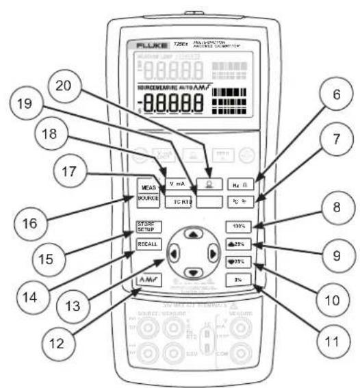
aly41f.eps
Figure 3. Keys
Table 4. Key Functions
| No. | Key Description | |
| 1 | 1 | Turns the power on and off. |
| 2 | V mALoop | Selects voltage, mA, or loop power measurement functions in the upper display.Clears the switch test. See “Switch Test”. |
| 3 | Selects the pressure measurement function in the upper display. Repeated pushes cycle through the different pressure units.Use for pressure switch test. See “Switch Test”. | |
| 4 | ZEROΩ | Zeros the pressure module reading. This applies to both upper and lower displays. |
| 5 | Turns backlight on and off. | |
| 6 | Hz Ω | Toggles between frequency and ohms measurement and sourcing functions. |
| 7 | °C °F | Toggles between Centigrade and Fahrenheit when in TC or RTD functions. |
| 8 | 100% | Recalls a source value from memory corresponding to 100 % of span and sets it as the source value. Press and hold to store the source value as the 100 % value. |
| 9 | ▲25% | Increments output by 25 % of span. |
| 10 | ▼25% | Decrements output by 25 % of span. |
| 11 | 0% | Recalls a source value from memory corresponding to 0 % of span and sets it as the source value. Press and hold to store the source value as the 0 % value. |
| 12 | Cycles through : ∧ Slow repeating 0 % - 100 % - 0 % ramp ∧ Fast repeating 0 % - 100 % - 0 % ramp □ Repeating 0 % - 100 % - 0 % ramp in 25 % steps | |
| No. Key | Description | |
| 1+131+13 |  | Disables Shut Down ModeEnables Shut Down Mode |
| 13 |  | Increases or decreases the source level.Cycles through the 2-, 3-, and 4-wire selections.Moves through the memory locations of calibrator setups.In Contrast Adjustment mode; up-darkens contrast, down-lightens contrast. |
| 14 | RECALL | Retrieves a previous calibrator setup from a memory location. |
| 15 |  | Saves the Calibrator setup. Saves Contrast Adjust setup. |
| 16 |  | Cycles the Calibrator through MEASURE and SOURCE modes in the lower display. |
| 17 |  | Selects the TC (thermocouple) measurement and sourcing function in the lower display.Repeated pushes cycle through the thermocouple types. |
| 18 |  | Toggles between voltage, mA sourcing, or mA simulate functions in the lower display. |
| 19 |  | Selects RTD (resistance temperature detector) measurement and sourcing function in lower display. Repeated pushes cycle through the RTD types. |
| 20 |  | Selects the pressure measurement and sourcing function. Repeated pushes cycle through the different pressure units. |
Display
Figure 4 shows the elements of the display.
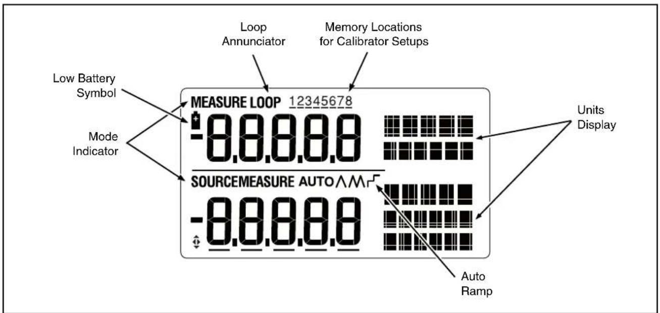
Figure 4. Elements of a Typical Display
sh07f.eps
Getting Started
This section introduces some basic operations of the Calibrator.
Proceed as follows to perform a voltage-to-voltage test:
- Connect the Calibrator's voltage output to its voltage input as shown in Figure 5.
- Press Ⓐ to turn on the Calibrator. Press V mA LOOP to select dc voltage (upper display).
- If necessary, press ☐ for SOURCE mode (lower display). The Calibrator is still measuring dc voltage; the active measurements are visible in the upper display.
-
Press V mA to select dc voltage sourcing.
-
Press ⏻ and ⏻ to select a digit to change. Press ⏻ to select 1 V for the output value. Press and hold [0%] to enter 1 V as the 0 % value.
- Press 🔒 to increase the output to 5 V. Press and hold 100% to enter 5 V as the 100 % value.
- Press ▲25% and ▼25% to step between 0 % and 100 % in 25 % step increments.
Shut Down Mode
The calibrator comes with the Shut Down mode enabled for a time duration set to 30 minutes (displayed for about 1 second when the calibrator is initially turned on). When the Shut Down mode is enabled, the calibrator will automatically shut down after the time duration has elapsed from the time the last key was pressed. To disable the Shut Down mode, press Ⓞ and ⏻ simultaneously. To enable the mode, press Ⓞ and ⏻ simultaneously. To adjust the time duration, press Ⓞ and ⏻ simultaneously, then press ⏻ and/or ⏻ to adjust the time between 1 minute and 30 minutes.
Mulitfunction Process Calibrator
Shut Down Mode
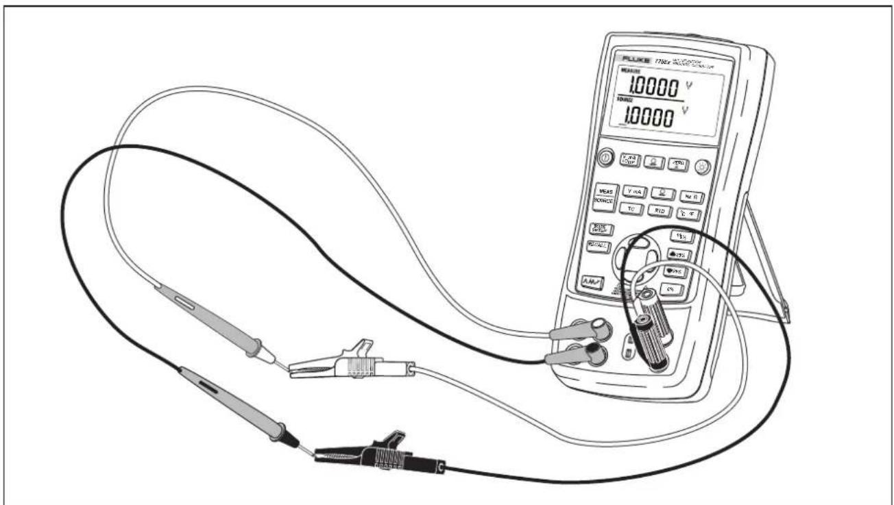
Figure 5. Voltage-to-Voltage Test
aly391.eps
725Ex
Users Manual
Contrast Adjustment
To adjust the contrast, proceed as follows:
- Press Ⓤ and Ⓐ until Contst Adjust is displayed as shown in Figure 6.
- Press and hold ⬆ to darken contrast.
- Press and hold ⬇ to lighten contrast.
- Press STORE SETUP to save the contrast level.
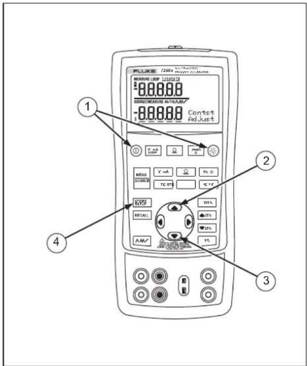
Figure 6. Adjusting the Contrast
sh06f.eps
Mulitfunction Process Calibrator
Using Measure Mode
Using Measure Mode
Measuring Electrical Parameters (Upper Display)
To measure the current or voltage output of a transmitter, or to measure the output of a pressure instrument, use the upper display and proceed as follows:
- Press mA to select volts or current. LOOP should not be on.
- Connect the leads as shown in Figure 7.
Current Measurement with Loop Power
The loop power function activates a 12-V supply in series with the current measuring circuit, allowing the user to test a transmitter when it is disconnected from plant wiring. To measure current with loop power, proceed as follows:
- Connect the Calibrator to the transmitter current loop terminals as shown in Figure 8.
- Press mA while the Calibrator is in current measurement mode. LOOP appears and an internal 12-V loop supply turns on.
725fs. 198000000
| V in dB | ||
| LOD* | 2000 | |
| NEAR | V mA | Hz |
| SOURCE | TC RTD | 6 F |
| APPRO | 100% | |
| RETAIL | 25% | |
| 56% | ||
| 0% | ||
Red
Black
aly42f.eps
Figure 7. Measuring Voltage and Current Output
725Ex
Users Manual
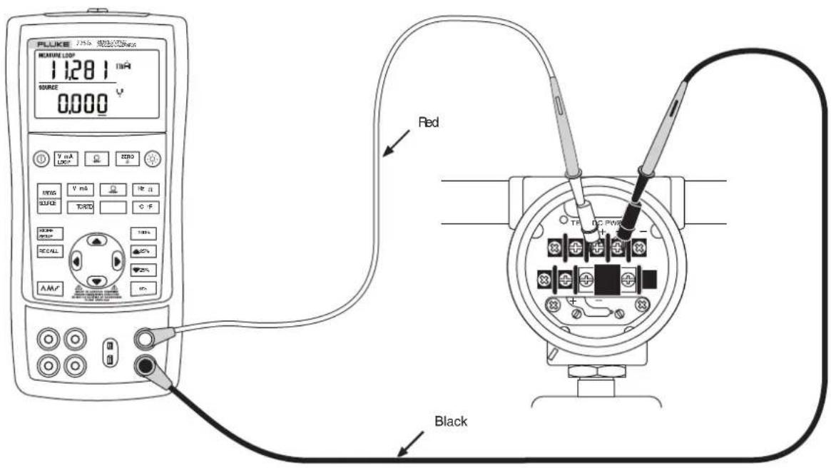
Figure 8. Connections for Supplying Loop Power
aly18f.ops
Mulitfunction Process Calibrator
Using Measure Mode
Measuring Electrical Parameters (Lower Display)
To measure the electrical parameters using the lower display, proceed as follows:
- Connect the Calibrator as shown in Figure 9.
- If necessary, press source for MEASURE mode (lower display).
- Press V mA for dc voltage or current, or Hz Ω for frequency or resistance.
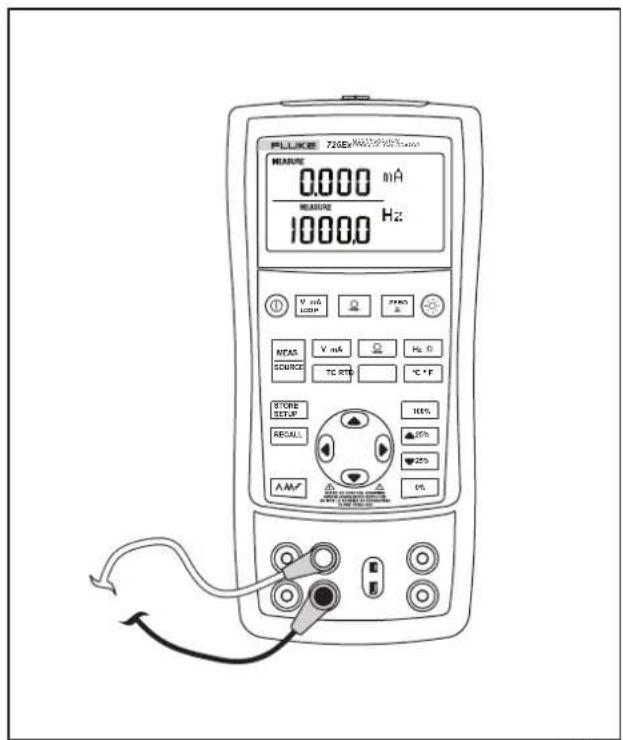
Figure 9. Measuring Electrical Parameters
aly431.eps
Measuring Temperature
Using Thermocouples
The Calibrator supports twelve standard thermocouples, including types E, N, J, K, T, B, R, S, L, XK, BP, and U. Table 5 summarizes the ranges and characteristics of the supported thermocouples.
To measure temperature using a thermocouple, proceed as follows:
- Attach the thermocouple leads to the appropriate TC miniplug, then to the TC input/output as shown in Figure 10.
Caution
One thermocouple pin is wider than the other. To avoid possible damage to Calibrator or to equipment under test do not try to force a miniplug in the wrong polarization.
Note
If the Calibrator and the thermocouple plug are at different temperatures, wait one minute or more for the connector temperature to stabilize after plugging the miniplug into the TC input/output.
-
If necessary, press NEAR SOURCE for MEASURE mode.
-
Press TC for the TC display. Continue pressing this key to select the desired thermocouple type. If necessary, toggle between °C or °F temperature units by pressing [°C °F].
Table 5. Thermocouple Types Accepted
| Type Positive Lead Material | Positive Lead (H) Color | Negative Lead Material | Specified Range (°C) | ||
| ANSI* IEC** | |||||
| E | Chromel Purple Violet Constantan | -200 to 950 | |||
| N | Ni-Cr-Si Orange Pink Ni-Si-Mg | -200 to 1300 | |||
| J | Iron White Black Constantan | -200 to 1200 | |||
| K | Chromel Yellow Green Alumel | -200 to 1370 | |||
| T | Copper | Blue | Brown | Constantan | -200 to 400 |
| B | Platinum (30 % Rhodium) | Gray | Platinum (6 % Rhodium) | 600 to 1800 | |
| R | Platinum (13 % Rhodium) | Black | Orange | Platinum | -20 to 1750 |
| S | Platinum (10 % Rhodium) | Black | Orange | Platinum | -20 to 1750 |
| L | Iron | Constantan | -200 to 900 | ||
| U | Copper | Constantan | -200 to 400 | ||
| XK | 90.5 % Ni + 9.5 % Cr | GOST | 56 % Cu + 44 % Ni | -200 to 800 | |
| Violet or Black | |||||
| BP | 95 % W + 5 % Re | Red or Pink | 80 % W + 20 % Re | 0 to 2500 | |
| *American National Standards Institute (ANSI) device negative lead (L) is always red. **International Electrotechnical Commission (IEC) device negative lead (L) is always white. | |||||
725Ex
Users Manual
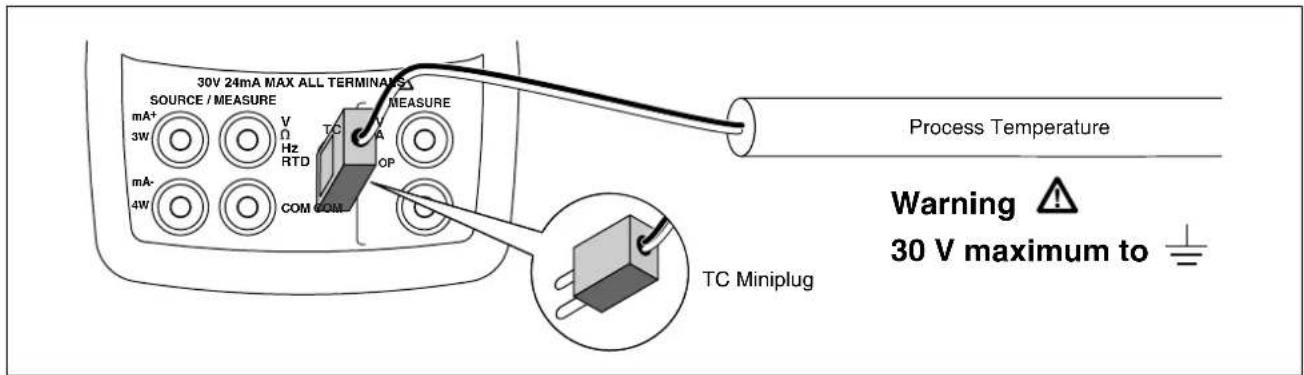
Figure 10. Measuring Temperature with a Thermocouple
aly12f.eps
Using Resistance-Temperature Detectors (RTDs)
The Calibrator accepts RTD types shown in Table 6. RTDs are characterized by their resistance at 0 °C ( 32 °F ), which is called the “ice point” or R_0 . The most common R_0 is 100 . The Calibrator accepts RTD measurement inputs in two-, three-, or four-wire connections, with the three-wire connection the most common. A four-wire configuration provides the highest measurement precision, and two-wire provides the lowest measurement precision.
To measure temperature using an RTD input, proceed as follows:
If necessary, press □ for MEASURE mode.
-
Press RTD for the RTD display. If desired, continue pressing this key to select the desired RTD type.
-
Press ☑ or ▼ to select a 2-, 3-, or 4- wire connection.
-
Attach the RTD to input terminals as shown in Figure 11.
-
If necessary, toggle between ^ C or ^ F temperature units by pressing ^ C ^ F.
Table 6. RTD Types Accepted
| RTD Type Ice | Point (R _0 ) Material | Range ( ^ ) | ||
| Pt100 (3926) | 100 | Platinum | 0.003926 /^ | -200 to 630 |
| Pt100 (385) | 100 | Platinum | 0.00385 /^ | -200 to 800 |
| Ni120 (672) | 120 | Nickel | 0.00672 /^ | -80 to 260 |
| Pt200 (385) | 200 | Platinum | 0.00385 /^ | -200 to 630 |
| Pt500 (385) | 500 | Platinum | 0.00385 /^ | -200 to 630 |
| Pt1000 (385) | 1000 | Platinum | 0.00385 /^ | -200 to 630 |
| Pt100 (3916) | 100 | Platinum | 0.003916 /^ | -200 to 630 |
| The IEC standard RTD and the most commonly used RTD in U.S. industrial applications is the Pt100 (385), = 0.00385 /^ . | ||||
Mulitfunction Process Calibrator
Using Measure Mode
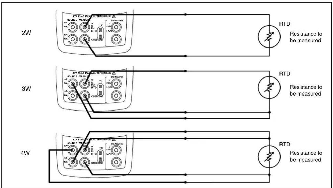
aly15f.eps
Figure 11. Measuring Temperature with an RTD, Measuring 2-, 3-, and 4-Wire Resistance
Measuring Pressure
Many ranges and types of pressure modules are available from Fluke. See “Accessories” near the back of this manual. Before using a pressure module, read its instruction sheet. The modules vary in use, media, and accuracy.
Figure 12 shows the Gage and Differential modules. Differential modules also work in gage mode by leaving the low fitting open to atmosphere.
To measure pressure, attach the appropriate pressure module for the process pressure to be tested
Proceed as follows to measure pressure:
⚠ Warning
To prevent fire, explosion, or personal injury:
- Use only Fluke pressure modules.
- To avoid a violent release of pressure in a pressurized system, shut off the valve and slowly bleed off the pressure before attaching the pressure module to the pressure line.
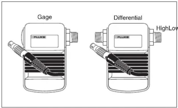
Figure 12. Gage and Differential Pressure Modules
Caution
- To avoid mechanically damaging the pressure module, never apply more than 10 lb-ft (13.5 Nm) of torque between the pressure module fittings, or between the fittings and the body of the module. Always apply appropriate torque between the pressure module fitting and connecting fittings or adapters.
-
To avoid damaging the pressure module from overpressure, never apply pressure above the rated maximum printed on the pressure module.
-
To avoid damaging the pressure module from corrosion, use it only with specified materials. Refer to the printing on the pressure module or the pressure module instruction sheet for the acceptable material compatibility.
- Connect a pressure module to the Calibrator as shown in Figure 13. The threads on the pressure modules accept standard 14 NPT pipe fittings. Use the supplied 14 NPT to 14 ISO adapter if necessary.
- Press ☐. The Calibrator automatically senses which pressure module is attached and sets its range accordingly.
- Zero the pressure module as described in the module's instruction sheet. Modules vary in zeroing procedures depending on module type, but all require pressing ZERO.
If desired, continue pressing ☐ to change pressure display units to psi, mmHg, inHg, cmH₂O@4 °C, cmH₂O@20 °C, inH₂O@4 °C, inH₂O@20 °C, inH₂O@60 °F, mbar, bar, kg/cm², or kPa.
Zeroing with Absolute Pressure Modules
To zero, adjust the Calibrator to read a known pressure. This can be barometric pressure, if it is accurately known. An accurate pressure standard can also apply a pressure within range for any absolute pressure module. To adjust the Calibrator reading, proceed as follows:
- Press ZERO, REF Adjust will appear to the right of the pressure reading.
- Use ⚙ to increase or ⚙ to decrease the Calibrator reading to equal the reference pressure.
- Press ZERO again to exit zeroing procedure.
The Calibrator stores and automatically reuses the zero offset correction for one absolute pressure module so that the module is not rezeroed every time it is used.
725Ex
Users Manual
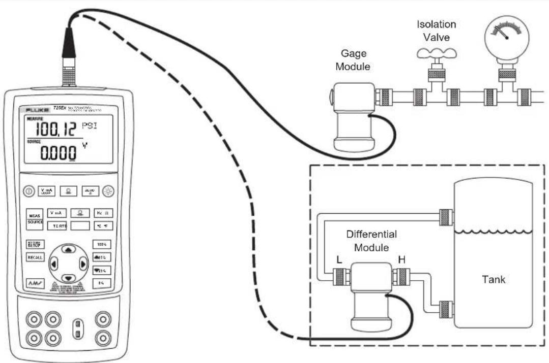
Figure 13. Connections for Measuring Pressure
aly371.eps
Using Source Mode
In SOURCE mode, the Calibrator generates calibrated signals for testing and calibrating process instruments; supplies voltages, currents, frequencies, and resistances; simulates the electrical output of RTD and thermocouple temperature sensors; and measures gas pressure from an external source, creating a calibrated pressure source.
Sourcing 4 to 20 mA
To select the current sourcing mode, proceed as follows:
- Connect the test leads in the mA terminals (left column).
- If necessary, press for SOURCE mode.
- Press V mA for current and enter the desired current by pressing 🔒 and ➕ keys. Press ⬇ and ⭁ to select a different digit to change.
Simulating a 4- to 20-mA Transmitter
Simulate is a special mode of operation in which the Calibrator is connected into a loop in place of a transmitter and supplies a known, settable test current. Proceed as follows:
Connect the 12-V-loop-power source as shown in Figure 14.
- If necessary, press for SOURCE mode.
- Press mA until both mA and SIM display.
- Enter the desired current by pressing ⚠ and ⏰ keys.
Sourcing Other Electrical Parameters
Volts, ohms, and frequency are also sourced and shown in the lower display.
To select an electrical sourcing function, proceed as follows:
- Connect the test leads as shown in Figure 15, depending on the source function.
- If necessary, press NEAS SOURCE for SOURCE mode.
- Press V mA for dc voltage, or Hz Ω for frequency or resistance.
- Enter the desired output value by pressing ⏻ and ⏻ keys. Press ⏻ and ⏻ to select a different digit to change.
725Ex
Users Manual
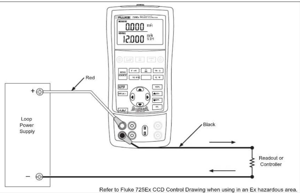
aly17f.eps
Figure 14. Connections for Simulating a 4 to 20- mA Transmitter in a non-Ex hazardous Area
Mulitfunction Process Calibrator
Using Source Mode
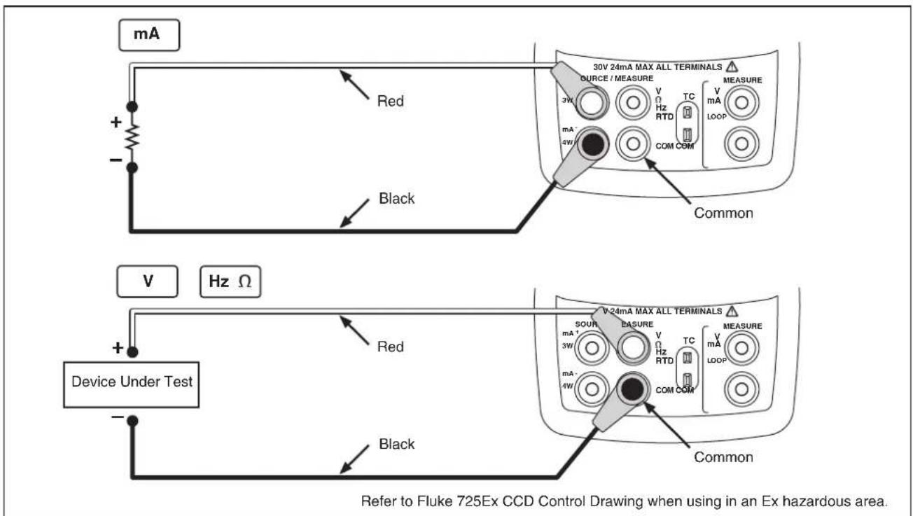
Figure 15. Electrical Sourcing Connections
aly16f.eps
Simulating Thermocouples
Connect the Calibrator TC input/output to the instrument under test with thermocouple wire and the appropriate thermocouple mini-connector (polarized thermocouple plug with flat, inline blades spaced 7.9 mm [0.312 in] center to center).
Caution
One pin is wider than the other. Do not try to force a miniplug in the wrong polarization.
Figure 16 shows this connection. Proceed as follows to simulate a thermocouple:
- Attach the thermocouple leads to the appropriate TC miniplug, then to the TC input/output as shown in Figure 16.
- If necessary, press for SOURCE mode.
- Press TC for the TC display. If desired, continue pressing this key to select the desired thermocouple type.
- Enter the desired temperature by pressing 🔒 and 🔑 keys. Press ⏻ and ⏱ to select a different digit to edit.
Simulating RTDs
Connect the Calibrator to the instrument under test as shown in Figure 17. Proceed as follows to simulate an RTD:
- If necessary, press for SOURCE mode.
- Press RTD for the RTD display.
Note
Use the 3W and 4W terminals for measurement only, not for simulation. The Calibrator simulates a 2-wire RTD at its front panel. To connect to a 3-wire or 4-wire transmitter, use the stacking cables to provide the extra wires. See Figure 17.
- Enter the desired temperature by pressing ⚙ and ⚡ keys. Press ⏻ and ⚽ to select a different digit to edit.
Mulitfunction Process Calibrator
Using Source Mode
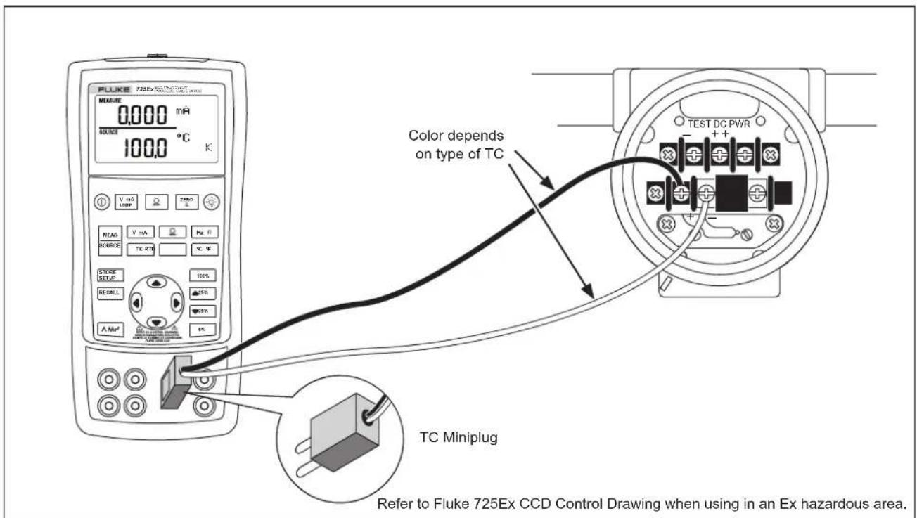
Figure 16. Connections for Simulating a Thermocouple
aly201.eps
725Ex
Users Manual
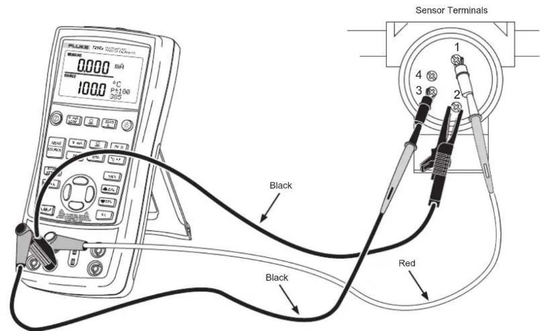
Refer to Fluke 725Ex CCD Control Drawing when using in an Ex hazardous area.
aly40f.ops
Figure 17. Connections for Simulating 3-Wire RTD
Source Pressure Mode
The Calibrator can be used to monitor the pressure supplied by a pump or other sources, and will display the pressure in the SOURCE field. Figure 18 shows how to connect a pump to a Fluke pressure module which makes it a calibrated source.
Attach the appropriate pressure module for the process pressure to be tested.
Proceed as follows to source pressure:
⚠ Warning
To prevent fire, explosion, or personal injury:
- Use only Fluke pressure modules.
- To avoid a violent release of pressure in a pressurized system, shut off the valve and slowly bleed off the pressure before attaching the pressure module to the pressure line.
Caution
- To avoid mechanically damaging the pressure module, never apply more than 10 lb-ft (13.5 Nm) of torque between the pressure module fittings, or between the fittings and the body of the module. Always apply appropriate torque between the pressure module fitting and connecting fittings or adapters.
- To avoid damaging the pressure module from overpressure, never apply pressure above the rated maximum printed on the pressure module.
- To avoid damaging the pressure module from corrosion, use it only with specified materials. Refer to the printing on the pressure module or the pressure module instruction sheet for the acceptable material compatibility.
725Ex
Users Manual
Connect a pressure module to the Calibrator as shown in Figure 18. The threads on the pressure modules accept standard 14 NPT pipe fittings. Use the supplied 14 NPT to 14 ISO adapter if necessary.
- Press ☐ (lower display). The Calibrator automatically senses which pressure module is attached and sets its range accordingly.
- Zero the pressure module as described in the module's Instruction Sheet. Modules vary in zeroing procedures depending on module type.
- Pressurize the pressure line with the pressure source to the desired level as shown on the display. If desired, continue pressing ☐ to change pressure display units to psi, mmHg, inHg, cmH₂O@4 °C, cmH₂O@20 °C, inH₂O@4 °C, inH₂O@20 °C, inH₂O@60 °F, mbar, bar, kg/cm², or kPa.
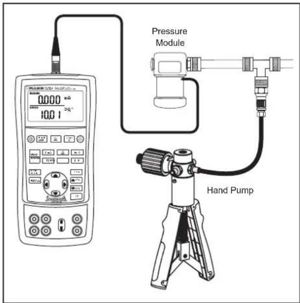
Figure 18. Connections for Sourcing Pressure
Setting 0 % and 100 % Output Parameters
For current output, the Calibrator assumes that 0 % corresponds to 4 mA and 100 % corresponds to 20 mA. For other output parameters, the 0 % and 100 % points must be set before use of the step and ramp functions. Proceed as follows:
- If necessary, press for SOURCE mode.
- Select the desired source function and use the arrow keys to enter the value. Our example is temperature source using 100 °C and 300 °C values for source.
- Enter 100 °C and press and hold 0% to store the value.
- Enter in 300 °C and press and hold 100% to store the value.
This setting may now be used for the following:
- Manually stepping an output with 25% increments.
- Jump between the 0 % and 100 % span points by momentarily pushing 0% or 100%.
Stepping and Ramping the Output
Two features are available for adjusting the value of source functions.
- Stepping the output manually with the ▲25% and ▼25% keys, or in automatic mode.
- Ramping the output.
Stepping and ramping apply to all functions except pressure, which requires use of an external pressure source.
Manually Stepping the mA Output
To manually step current output, do the following:
- Use ▲25% or ▼25% to step the current up or down in 25 % steps.
- Touch momentarily either 0% to go to 0%, or 100% to go to 100%.
Auto Ramping the Output
Auto ramping gives the ability to continuously apply a varying stimulus from the Calibrator to a transmitter, while your hands remain free to test the response of the transmitter.
When M_1F is pressed, the Calibrator produces a continuously repeating 0 % - 100 % - 0 % ramp in a choice of three ramp waveforms:
0 % - 100 % - 0 % 40-second smooth ramp
M 0% - 100% - 0% 15-second smooth ramp
0% - 100% - 0% Stair-step ramp in 25% steps, pausing 5 seconds at each step. Steps are listed in Table 7.
To exit ramping, press any button.
Table 7. mA Step Values
| Step 4 to 20 m | A | |
| 0 % | 4.000 | |
| 25 % | 8.000 | |
| 50 % | 12.000 | |
| 75 % | 16.000 | |
| 100 % | 20.000 | |
Storing and Recalling Setups
Store up to eight settings in a nonvolatile memory and recall the settings for later use. A low battery condition or a battery change does not jeopardize the stored settings. Proceed as follows:
- After creating a calibrator setup, press STORE SETUP. In the display, the memory locations appear.
- Press ⏻ or ⏻ to select locations one through eight. An underscore appears below the selected memory location.
- Press STORE SETUP until the memory number disappears then reappears. The setup is stored.
To recall setups, proceed as follows.
-
Press RECALL. The memory locations appear on the display.
-
Press ☐ or ☑ to select the appropriate location and press RECALL.
Calibrating a Transmitter
Use the measurement (upper display) and source (lower display) modes to calibrate a transmitter. This section applies to all but pressure transmitters. The following example shows how to calibrate a temperature transmitter.
Connect the Calibrator to the instrument under test as shown in Figure 19. Proceed as follows to calibrate a transmitter
- Press mA for current (upper display). If required, press mA again to activate loop power.
- Press TC (lower display). If desired, continue pressing this key to select the desired thermocouple type.
-
If necessary, press for SOURCE mode.
-
Set the zero and span parameters by pressing 📊 and 🔒 keys. Enter these parameters by pressing and holding 0% and 100%. For more information on setting parameters, see "Setting 0 % and 100 %" earlier in this manual.
-
Press ⏻ or ⏻ to select the appropriate location
-
Perform test checks at 0-25-50-75-100 % points by pressing ▲25% or ▼25%. Adjust the transmitter as necessary.
725Ex
Users Manual
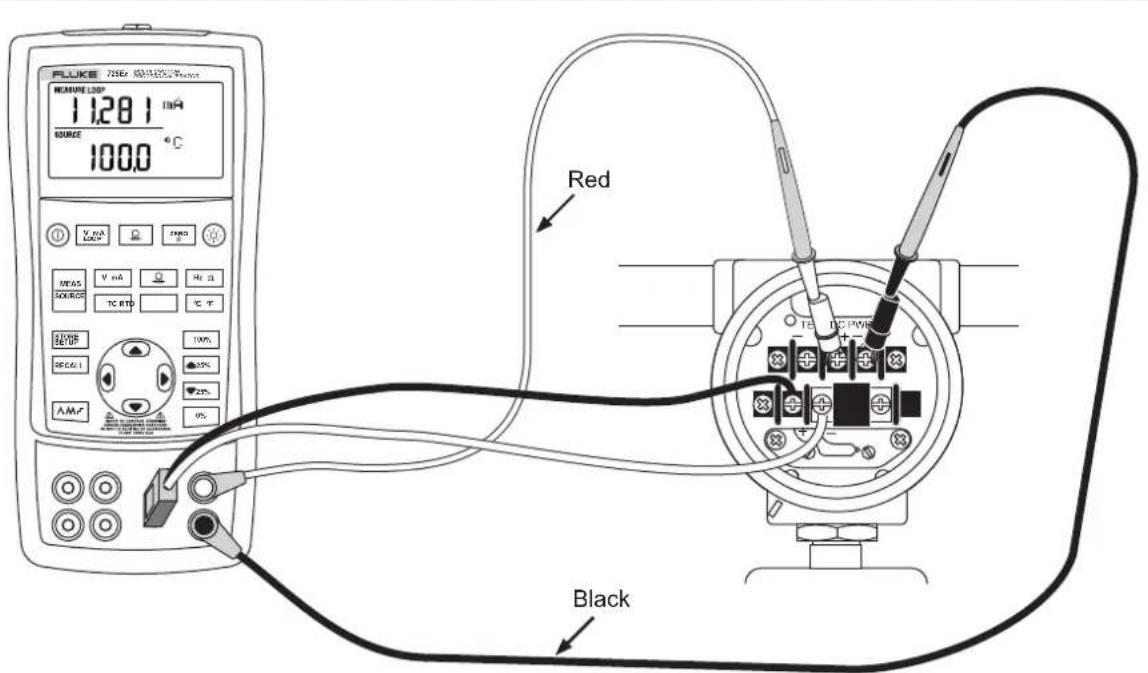
Refer to Fluke 725Ex CCD Control Drawing when using in an Ex hazardous area.
aly441.ops
Figure 19. Calibrating a Thermocouple Transmitter
Calibrating a Pressure Transmitter
The following example shows how to calibrate a pressure transmitter.
Connect the Calibrator to the instrument under test as shown in Figure 20. Proceed as follows:
- Press mA for current (upper display). If required, press mA again to activate loop power.
- Press ☐ (lower display).
- If necessary, press for SOURCE mode.
- Zero the pressure module.
- Perform checks at 0 % and 100 % of span and adjust the transmitter as necessary.
725Ex
Users Manual
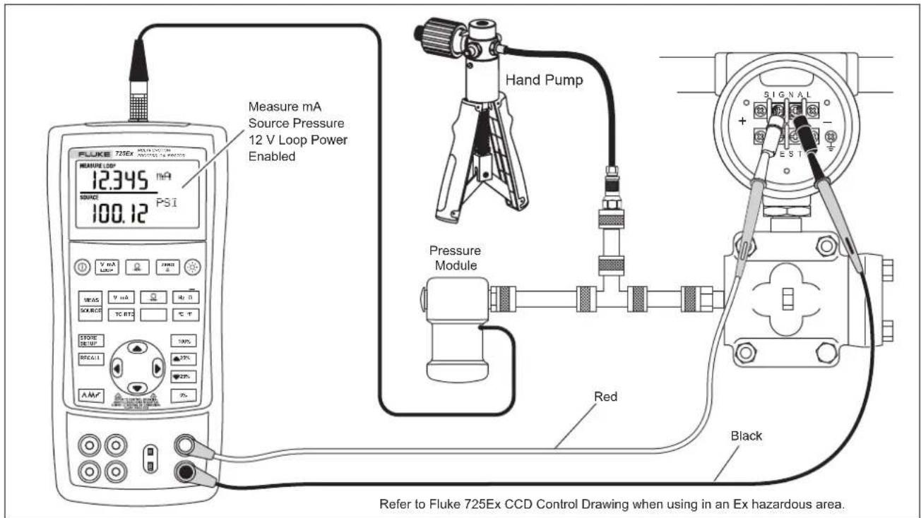
Figure 20. Calibrating a Pressure-to-Current (P/I) Transmitter
aly34f.ops
Calibrating an I/P Device
The following test allows calibration of a device that controls pressure. Proceed as follows:
- Connect the test leads to the instrument under test as shown in Figure 21. The connections simulate a current-to-pressure transmitter and measures the corresponding output pressure.
- Press ☐ (upper display).
- Press mA for sourcing current (lower display).
- If necessary, press for SOURCE mode.
- Enter the desired current by pressing 🔒 and ▼ keys. Press ⏻ and ⭺ to select different digits.
725Ex
Users Manual
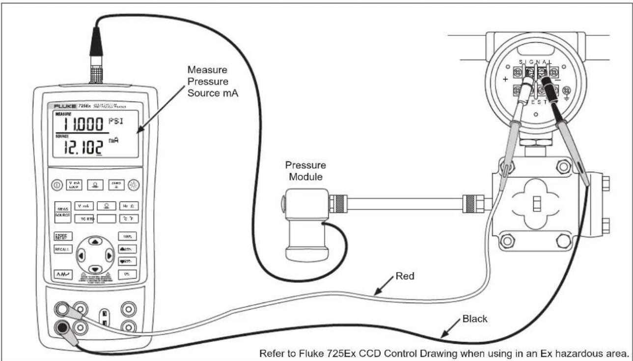
Figure 21. Calibrating a Current-to-Pressure (I/P) Transmitter
aly28f.ops
Switch Test
To perform a switch test, follow these steps:
Note
This example used a normally closed switch. The procedure is the same for an open switch but the display reads OPEN instead of CLOSE.
- Connect the Calibrator mA and COM terminals to the switch using the pressure switch terminals and connect the pump from the Calibrator to the pressure switch. The polarity of the terminals does not matter.
- Make sure the vent on the pump is open and zero the Calibrator if necessary. Close the vent after zeroing the Calibrator.
- Press and hold the upper display ⚠️ button for three seconds to enter switch test mode. The upper main display indicates the applied pressure, CLOSE will be displayed to the right of the pressure reading to indicate closed contacts
- Apply pressure with the pump slowly until the switch opens.
Note
Pressure the device slowly to ensure accurate readings. Run the test several times to confirm repeatability.
- OPEN displays once the switch is open. Bleed the pump slowly until the pressure switch closes. RECALL appears on the display.
- Press ☐ to read the pressure values for when the switch opened, for when it closed, and for the deadband.
- Hold ☐ for three seconds to exit the switch test or press V mA Loop to clear the switch test and rerun the test.
725Ex
Users Manual
Testing an Output Device
Use the source functions to test and calibrate actuators, recording, and indicating devices. Proceed as follows:
- Connect the test leads to the instrument under test as shown in Figure 22.
- Press V mA for current or dc voltage, or Hz Ω for frequency or resistance (lower display).
- If necessary, press ☐ for SOURCE mode.
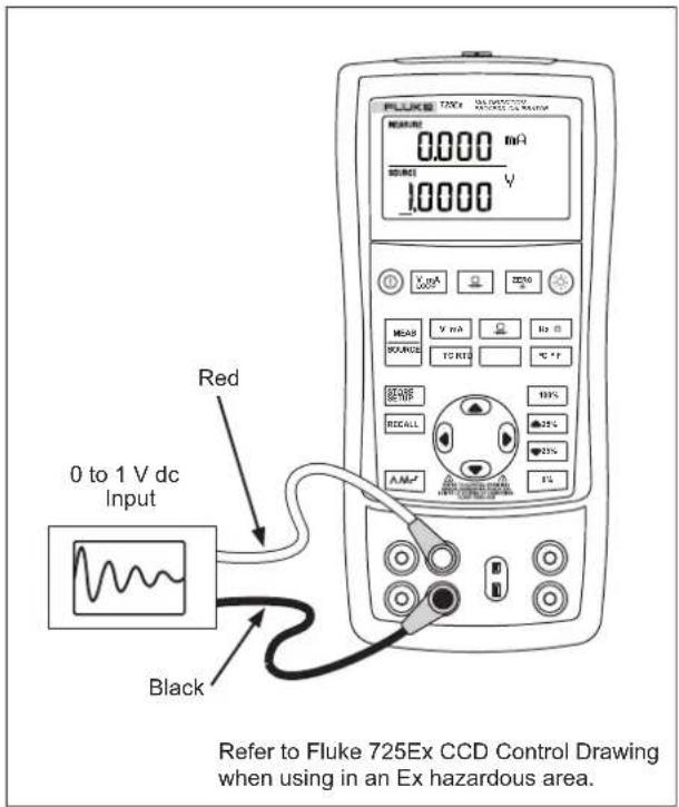
Figure 22. Calibrating a Chart Recorder
aly25f.eps
Mulitfunction Process Calibrator
Replacing the Batteries
Replacing the Batteries
⚠ Warning
To prevent fire, explosion, or personal injury:
- Remove the Calibrator from the Ex-hazardous area before opening the battery door. See Ex Hazardous Areas.
Figure 23 shows how to replace the batteries.
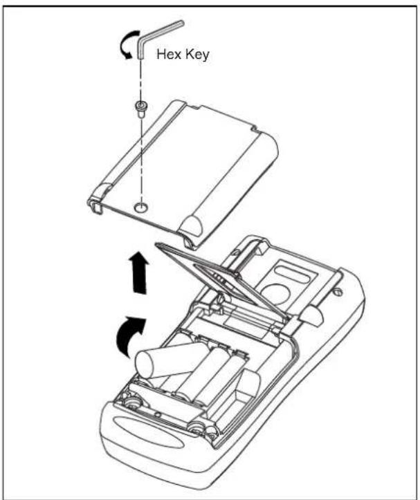
Figure 23. Replacing the Batteries
725Ex
Users Manual
Approved Batteries
Table 8. Approved Batteries
| Battery Manufacturer(All Batteries Alkaline- AA 1.5 V) | Type |
| Duracell MN1500 | |
| Eveready (Energizer) E91 |
Maintenance
Cleaning the Calibrator
Warning
To avoid personal injury or damage to the Calibrator, use only the specified replacement parts and do not allow water into the case.
Caution
To avoid damaging the plastic lens and case, do not use solvents or abrasive cleansers.
Clean the Calibrator and pressure modules with a soft cloth dampened with water or water and mild soap.
Mulitfunction Process Calibrator
Maintenance
Service Center Calibration or Repair
Calibration, repairs, or servicing must be performed only by qualified service personnel. If the Calibrator fails, check the batteries first, and replace them if needed.
Verify that the Calibrator is being operated in accordance with the instructions in this manual. If the Calibrator is faulty, send a description of the failure with the Calibrator. Pressure modules do not need to accompany the Calibrator unless the module is faulty also. Be sure to pack the Calibrator securely, using the original shipping container if it is available. Send the equipment postage paid and insured, to the nearest Service Center. Fluke assumes no responsibility for damage in transit.
The Fluke 725Ex Calibrator covered by the warranty will be promptly repaired or replaced (at Fluke's option) and returned to you at no charge. See the back of the title page for warranty terms. If the warranty period has expired or the operating limits are exceeded, the
Calibrator will be repaired and returned for a fixed fee. If the Calibrator or pressure module is not covered under the warranty terms, contact an authorized service center for a price quote for repair.
To locate an authorized service center or order replacement parts, refer to "Contacting Fluke" at the beginning of the manual.
Replacement Parts
Table 9 lists the part number of each replaceable part.
Table 9. Replacement Parts
| Description PN Qty. | ||
| AA alkaline batteries See “Table 8. Approved Batteries” | 4 | |
| Battery door 2097832 | 1 | |
| Accessory mount 2151981 | 1 | |
| Tilt stand 2097826 | 1 | |
| TL75 series test setCap, BlackCap, Red | 85574239865683995524 | 111 |
| Fluke – 7XX Test Lead Set 3397308 | 1 | |
| AC175Alligator clip, redAlligator clip, black | 42390924239050 | 11 |
| Input Decal 690948 | 1 | |
| Fluke 725Ex Control Drawing | 4926220 | 1 |
| Fluke 725Ex Safety Information | 2151996 | 1 |
Accessories
For more information about these accessories and their prices, contact a Fluke representative. Pressure Modules and Fluke model numbers (see Table 10) are listed below. (Differential models also operate in gage mode.) Contact a Fluke representative about new pressure modules not listed here.
• 700HTP-2 0 to 10,000 PSI Pump
• 700PTP-1 -11.6 to 600 PSI Pump
• 700TC1 and 700TC2 Thermocouple Mini-plug Kits
External Fluke Pressure Module Compatibility
The output of Fluke 750PEx pressure modules can cause the 5 digit display of the Calibrator to overflow, or else produce values that are too low to be read if inappropriate units are selected. This is prevented by displaying OL on the display per Table 10.
Table 10. Fluke Pressure Module Compatibility
| Pressure Unit Module Compatibility | |
| psi Available on all pressure ranges | |
| inH20 All ranges through 3000 psi | |
| cmH20 All ranges through 1000 psi | |
| bar 15 psi and above | |
| mbar All ranges through 1000 psi | |
| kPa Available on all pressure ranges | |
| inHg Available on all pressure ranges | |
| mmHg | All ranges through 1000 psi |
| kg/cm2 | 15 psi and above |
Table 11. Pressure Modules
| Fluke Model Number Range | Type and Media | |
| Fluke-750P01Ex 0 inH20 | to 10 inH20 differential, Low: dry High: dry | |
| Fluke-750P24Ex 0 psi to | 15 psi differential, Low: dry High: wet | |
| Fluke-750P05Ex 0 psi to | 30 psi gage, wet | |
| Fluke-750P06Ex 0 psi to | 100 psi gage, wet | |
| Fluke-750P09Ex 0 psi to | 1500 psi gage, wet | |
| Fluke-750P27Ex 0 psi to | 300 psi gage, wet | |
| Fluke-750P29Ex 0 psi to | 3000 psi gage, wet | |
| Fluke-750PA4Ex 0 psi to | 15 psi absolute, Low: dry High: wet |
Specifications
All specifications apply from +18 °C to +28 °C unless stated otherwise. All specifications assume a 5-minute warmup period.
DC Voltage Measurement
| Range Resolution | Accuracy, (% of Reading + Counts) | |
| 30 V (upper display) | 0.001 V 0.02 % | + 2 |
| 10 V (lower display) | 0.001 V 0.02 % | + 2 |
| 90 mV 0.01 | mV 0.02 % + 2 | |
| Temperature coefficient -10 °C to 18 °C, +28 °C to 55 °C: ±0.005 % of range per °C | ||
DC Voltage Source
| Range | Resolution | Accuracy, (% of Reading + Counts) |
| 100 mV | 0.01 mV 0.02 % + | 2 |
| 10 V | 0.001 V 0.02 % + 2 | |
| Temperature coefficient -10 °C to 18 °C, +28 °C to 55 °C: ±0.005 % of range per °CMaximum load: 1 mA | ||
Millivolt Measurement and Source*
| Range Resolution Accuracy | ||
| -10 mV to 75 mV | 0.01 mV | ± (0.025 % + 1 count) |
| Maximum input voltage: 30 VTemperature coefficient -10 °C to 18 °C, +28 °C to 55 °C: ± 0.005 % of range per ^ *Select this function by pressing TC. The signal is available at the thermocouple miniplug connector. | ||
DC mA Measurement and Source
| Range | Resolution | Accuracy, (% of Reading + Counts) |
| 24 mA | 0.01 mA 0.02 % | + 2 |
| Temperature coefficient -10 °C to 18 °C, +28 °C to 55 °C: ±0.005 % of range per °CDrive capability: 250 Ω at 20 mA | ||
Ohms Measurement
| Ohms Range | Accuracy ± ^* | |
| 4-Wire 2- and 3-Wire | ||
| 0 Ω to 400 Ω | 0.1 0.15 | |
| 400 Ω to 1.5 kΩ | 0.5 1.0 | |
| 1.5 kΩ to 3.2 kΩ | 1 1.5 | |
| Temperature coefficient -10 °C to 18 °C, +28 °C to 55 °C: ±0.005 % of range per °CExcitation Current: 0.2 mAMaximum input voltage: 30 V* 2-wire: Does not include lead resistance.3-wire: Assumes matched leads with a total resistance not exceeding 100 Ω. | ||
Ohms Source
| Ohms Range | Excitation Current from Measurement Device | Accuracy ± Ω |
| 15 Ω to 400 Ω | 0.15 mA to 0.5 mA 0.15 | |
| 15 Ω to 400 Ω | 0.5 mA to 2 mA 0.1 | |
| 400 Ω to 1.5 kΩ | 0.05 mA to 0.8 mA 0.5 | |
| 1.5 kΩ to 3.2 kΩ | 0.05 mA to 0.4 mA 1 | |
| Temperature coefficient -10 °C to 18 °C, +28 °C to 55 °C: ± 0.005 % of resistance range per °C | ||
| Resolution | ||
| 15 Ω to 400 Ω | 0.1 Ω | |
| 400 Ω to 3.2 kΩ | 1 Ω | |
Frequency Measurement
| Range Resolution Accuracy | ||
| 2.0 CPM to 1000.0 CPM | 0.1 CPM | ± (0.05 % + 1 count) |
| 1 Hz to 1000 Hz | 1.0 Hz | ± (0.05 % + 1 count) |
| 1.0 kHz to 10.0 kHz 0.1 kHz | ± (0.05 % + 1 count) | |
| Sensitivity: 1 V peak-to-peak minimumWaveform: squarewave | ||
Multifunction Process Calibrator
Specifications
Frequency Source
| Range Resolution | Accuracy(% of output frequency) |
| 2.0 CPM to 1000.0 CPM 0.1 CPM | ±0.05 % |
| 1 Hz to 1000 Hz 1 Hz | ±0.05 % |
| 1.0 kHz to 10.0 kHz 0.1 kHz | ±0.25 % |
| Waveform: 5 V p-p squarewave, -0.1 V offset | |
Temperature, Thermocouples
| Type | Range | Measure and Source Accuracies |
| J | -200 °C to 0 °C | 1.0 °C |
| 0 °C to 1200 °C | 0.7 °C | |
| K | -200 °C to 0 °C | 1.2 °C |
| 0 °C to 1370 °C | 0.8 °C | |
| T | -200 °C to 0 °C | 1.2 °C |
| 0 °C to 400 °C | 0.8 °C | |
| E | -200 °C to 0 °C | 0.9 °C |
| 0 °C to 950 °C | 0.7 °C | |
| R | -20 °C to 0 °C | 2.5 °C |
| 0 °C to 500 °C | 1.8 °C | |
| 500 °C to 1750 °C | 1.4 °C | |
| S | -20 °C to 0 °C | 2.5 °C |
| 0 °C to 500 °C | 1.8 °C | |
| 500 °C to 1750 °C | 1.5 °C |
| Type | Range | Measure and Source Accuracies |
| B | 600 °C to 800 °C | 2.2 °C |
| 800 °C to 1000 °C | 1.8 °C | |
| 1000 °C to 1800 °C | 1.4 °C | |
| L | -200 °C to 0 °C | 0.85 °C |
| 0 °C to 900 °C | 0.7 °C | |
| U | -200 °C to 0 °C | 1.1 °C |
| 0 °C to 400 °C | 0.75 °C | |
| N | -200 to 0 °C | 1.5 °C |
| 0 °C to 1300 °C | 0.9 °C | |
| XK | -200 °C to 100 °C | 0.5 °C |
| -100 °C to 800 °C | 0.6 °C | |
| BP | 0 °C to 800 °C | 1.2 °C |
| 800 °C to 2500 °C | 2.5 °C | |
| Resolution:0.1 °C, 0.1 °F | ||
Loop Power Supply
Voltage: 12 V
Maximum current: 24 mA
Short circuit protected
RTD Excitation (simulation)
| Allowable Excitation by RTD type | |
| Ni 120 0.15 mA to 3.0 mA | |
| Pt 100-385 0.15 mA to 3.0 mA | |
| Pt 100-3926 0.15 mA to 3.0 mA | |
| Pt 100-3916 0.15 mA to 3.0 mA | |
| Pt 200-385 0.05 mA to 0.80 mA | |
| Pt 500-385 0.05 mA to 0.80 mA | |
| Pt 1000-385 0.05 mA to 0.40 mA | |
Temperature, RTD Ranges, and Accuracies
| AccuracyType | Range °C | |||
| Measure 4-Wire °C | Measure 2- and 3-Wire* °C | Source °C | ||
| Ni120 -80 to 260 | 0.2 0.3 0.2 | |||
| Pt100-385 - 200 to | 800 0.33 | 0.5 0.33 | ||
| Pt100-3926 | -200 to 630 | 0.3 0.5 0.3 | ||
| Pt100-3916 | -200 to 630 | 0.3 0.5 0.3 | ||
| Pt200-385 -200 to | 250 | 0.2 | 0.3 | 0.2 |
| 250 to 630 | 0.8 | 1.6 | 0.8 | |
| Pt500-385 -200 to | 500 | 0.3 | 0.6 | 0.3 |
| 500 to 630 | 0.4 | 0.9 | 0.4 | |
| Pt1000-385 | -200 to 100 | 0.2 | 0.4 | 0.2 |
| 100 to 630 | 0.2 | 0.5 | 0.2 | |
| Resolution: 0.1 °C, 0.1 °FRTD Source: Addresses pulsed transmitters and PLCs with pulses as short as 5 ms.* 2-wire: Does not include lead resistance.3-wire: Assumes matched leads with a total resistance not exceeding 100 Ω. | ||||
Multifunction Process Calibrator
Specifications
Pressure Measurement
| Range Reso | ution Accuracy | Units | |
| Determined by pressure module | 5 digits Determined by pressure module | psi, inH2O@4 °C, inH2O@20 °C, inH2O@60 °F, kPa, cmH2O@4 °C, cmH2O@20 °C, bar, mbar, kg/cm2, mmHg, inHg | |
General Specifications
| Operating temperature | -10 °C to 55 °C |
| Storage temperature | -20 °C to 71 °C |
| Operating altitude | 3000 meters above mean sea level |
| Pollution Degree | 2 |
| Relative Humidity(% RH operating without condensation) | 90 % (10 °C to 30 °C)75 % (30 °C to 40 °C)45 % (40 °C to 50 °C)35 % (50 °C to 55 °C)uncontrolled <10 °C |
| Vibration | Random, 2 g, 5 Hz to 500 Hz |
725Ex
Users Manual
| Electromagnetic compatibility (EMC)International | IEC 61326-1: PortableCISPR 11: Group 1, Class AGroup 1: Equipment has intentionally generated and/or uses conductively-coupled radio frequency energy that is necessary for the internal function of the equipment itself.Class A: Equipment is suitable for use in all establishments other than domestic and those directly connected to a low-voltage power supply network that supplies buildings used for domestic purposes. There may be potential difficulties in ensuring electromagnetic compatibility in other environments due to conducted and radiated disturbances.Caution: This equipment is not intended for use in residential environments and may not provide adequate protection to radio reception in such environments. |
| Korea (KCC) | Class A Equipment (Industrial Broadcasting & Communication Equipment)Class A: Equipment meets requirements for industrial electromagnetic wave equipment and the seller or user should take notice of it. This equipment is intended for use in business environments and not to be used in homes. |
| USA (FCC) | 47 CFR 15 subpart B. This product is considered an exempt device per clause 15.103. |
| Power requirements | 4 AA alkaline batteries- See “Approved Batteries” |
| Size | 96 mm x 200 mm x 47 mm (3.75 in x 7.9 in x 1.86 in) |
| Weight | 650 gm (1 lb, 7 oz) |
Entity Parameters
For Entity Parameters, Refer to Fluke 725Ex CCD, Control Drawing for use in Ex hazardous areas.
- LIMITED WARRANTY AND LIMITATION OF LIABILITY
- Table of Contents
- Title Page
- Contents
- Multifunction Process Calibrator
- Introduction
- ⚠ Warning
- Read "Safety Information" before using the Calibrator.
- Contact Fluke
- Standard Equipment
- Safety Information
- Ex Hazardous Areas
- 725Ex
- Users Manual
- Caution
- Faults and Damage
- Safety Regulations
- Certification Information
- Getting Acquainted with the Calibrator
- Input and Output Terminals
- Keys
- Display
- Getting Started
- Shut Down Mode
- Contrast Adjustment
- Mulitfunction Process Calibrator
- Using Measure Mode
- Measuring Electrical Parameters (Upper Display)
- Current Measurement with Loop Power
- Measuring Electrical Parameters (Lower Display)
- Measuring Temperature
- Using Thermocouples
- Using Resistance-Temperature Detectors (RTDs)
- Measuring Pressure
- Zeroing with Absolute Pressure Modules
- Using Source Mode
- Sourcing 4 to 20 mA
- Simulating a 4- to 20-mA Transmitter
- Sourcing Other Electrical Parameters
- Simulating Thermocouples
- One pin is wider than the other. Do not try to force a miniplug in the wrong polarization.
- Simulating RTDs
- Source Pressure Mode
- Setting 0 % and 100 % Output Parameters
- Stepping and Ramping the Output
- Manually Stepping the mA Output
- Auto Ramping the Output
- Storing and Recalling Setups
- Calibrating a Transmitter
- Calibrating a Pressure Transmitter
- Calibrating an I/P Device
- Switch Test
- Note
- Testing an Output Device
- Replacing the Batteries
- Approved Batteries
- Maintenance
- Warning
- Service Center Calibration or Repair
- Replacement Parts
- Accessories
- External Fluke Pressure Module Compatibility
- Specifications
- Loop Power Supply
- Entity Parameters
Brand : FLUKE
Model : 725Ex
Category : Security