
1742 - Energy meter FLUKE - Free user manual and instructions
Find the device manual for free 1742 FLUKE in PDF.


| Product Type | Power Quality Logger / Energy Meter |
| Brand | Fluke |
| Model | 1742 |
| Dimensions | 23.0 cm x 18.0 cm x 5.4 cm (9.1 in x 7.1 in x 2.1 in) |
| Weight | 1 kg (2.2 lb) |
| Power Supply | 100 V to 500 V via measurement inputs, or 100 V to 240 V via MA-C8 mains adapter |
| Battery | Li-ion 3.7 V, 8.5 Wh, customer-replaceable; typical runtime 4 hours |
| Measurement Functions | Voltage, current, power (kW, kVA, kvar), energy (kWh, kVAh, kvarh), frequency, THD, harmonics (up to 50th), flicker, unbalance, events (dips, swells, interruptions, RVC, inrush, waveform deviation) |
| Logging Intervals | Trend: 1 s to 30 min; Demand: 5 min to 30 min; PQ: 10 min; Harmonics: 150/180 cycles (3 s typical) |
| Data Storage | Internal flash memory, typical 20 logging sessions of 4 weeks with 1-min intervals and 500 events |
| Interfaces | USB-A, Mini-USB, Ethernet, WiFi (direct and infrastructure), WiFi/BLE adapter, GPS receiver port |
| Safety Rating | CAT IV 600 V / CAT III 1000 V; IEC 61010-1, Pollution Degree 2 |
| IP Rating | IP50 (standard), IP65 with IP65 rated voltage connector |
| Operating Temperature | -25 °C to +50 °C (-13 °F to +122 °F); warm up to -10 °C before power-on |
| Storage Temperature | -25 °C to +60 °C (-13 °F to +140 °F) without battery; -20 °C to +50 °C with battery |
| Humidity (Operating) | IEC60721-3-3 3K6: -25 °C to +30 °C: ≤100%; 40 °C: 55%; 50 °C: 35% |
| Altitude (Operating) | 2000 m (up to 4000 m derated to CAT II 1000 V / CAT III 600 V / CAT IV 300 V) |
| Warranty | Logger: 2 years; Accessories: 1 year |
| Calibration Cycle | 2 years |
| Included Accessories | Soft storage bag, voltage test leads (3-phase + N), alligator clips, cable markers, mains power cable, MA-C8 adapter, test leads (stack and non-stackable), USB cable, documentation, magnet hanger kit (1748 only), iFlexi current probes (model dependent), WiFi adapter(s) |
| Optional Upgrades | 1742-6/Upgrade (to 1746 features), 1742-8/Upgrade (to 1748 features), IEEE 519/Report license, GPS receiver, additional current probes |
| Maintenance | Clean with damp cloth (no abrasives or solvents); replace battery after 5 years; service by approved technician |
Frequently Asked Questions - 1742 FLUKE
User questions about 1742 FLUKE
0 question about this device. Answer the ones you know or ask your own.
Ask a new question about this device
Download the instructions for your Energy meter in PDF format for free! Find your manual 1742 - FLUKE and take your electronic device back in hand. On this page are published all the documents necessary for the use of your device. 1742 by FLUKE.
USER MANUAL 1742 FLUKE
Power Quality Logger
Users Manual

October 2017 Rev. 1, 3/20
©2017-2020 Fluke Corporation. All rights reserved.
All product names are trademarks of their respective companies.
LIMITED WARRANTY AND LIMITATION OF LIABILITY
Each Fluke product is warranted to be free from defects in material and workmanship under normal use and service. The warranty period is two years and begins on the date of shipment. Parts, product repairs, and services are warranted for 90 days. This warranty extends only to the original buyer or end-user customer of a Fluke authorized reseller, and does not apply to fuses, disposable batteries, or to any product which, in Fluke's opinion, has been misused, altered, neglected, contaminated, or damaged by accident or abnormal conditions of operation or handling. Fluke warrants that software will operate substantially in accordance with its functional specifications for 90 days and that it has been properly recorded on non-defective media. Fluke does not warrant that software will be error free or operate without interruption.
Fluke authorized resellers shall extend this warranty on new and unused products to end-user customers only but have no authority to extend a greater or different warranty on behalf of Fluke. Warranty support is available only if product is purchased through a Fluke authorized sales outlet or Buyer has paid the applicable international price. Fluke reserves the right to invoice Buyer for importation costs of repair/replacement parts when product purchased in one country is submitted for repair in another country.
Fluke's warranty obligation is limited, at Fluke's option, to refund of the purchase price, free of charge repair, or replacement of a defective product which is returned to a Fluke authorized service center within the warranty period.
To obtain warranty service, contact your nearest Fluke authorized service center to obtain return authorization information, then send the product to that service center, with a description of the difficulty, postage and insurance prepaid (FOB Destination). Fluke assumes no risk for damage in transit. Following warranty repair, the product will be returned to Buyer, transportation prepaid (FOB Destination). If Fluke determines that failure was caused by neglect, misuse, contamination, alteration, accident, or abnormal condition of operation or handling, including overvoltage failures caused by use outside the product's specified rating, or normal wear and tear of mechanical components, Fluke will provide an estimate of repair costs and obtain authorization before commencing the work. Following repair, the product will be returned to the Buyer transportation prepaid and the Buyer will be billed for the repair and return transportation charges (FOB Shipping Point).
THIS WARRANTY IS BUYER'S SOLE AND EXCLUSIVE REMEDY AND IS IN LIEU OF ALL OTHER WARRANTIES, EXPRESS OR IMPLIED, INCLUDING BUT NOT LIMITED TO ANY IMPLIED WARRANTY OF MERCHANTABILITY OR FITNESS FOR A PARTICULAR PURPOSE. FLUKE SHALL NOT BE LIABLE FOR ANY SPECIAL, INDIRECT, INCIDENTAL OR CONSEQUENTIAL DAMAGES OR LOSSES, INCLUDING LOSS OF DATA, ARISING FROM ANY CAUSE OR THEORY.
Since some countries or states do not allow limitation of the term of an implied warranty, or exclusion or limitation of incidental or consequential damages, the limitations and exclusions of this warranty may not apply to every buyer. If any provision of this Warranty is held invalid or unenforceable by a court or other decision-maker of competent jurisdiction, such holding will not affect the validity or enforceability of any other provision.
Fluke Corporation
P.O. Box 9090
Everett, WA 98206-9090
U.S.A.
Fluke Europe B.V.
P.O. Box 1186
5602 BD Eindhoven
The Netherlands
11/99
Documentation and Software Notice
Register the product at www.fluke.com/register to get the download link for the user manuals and the PC software Energy Analyze Plus. For software licensing information, visit www.fluke.com/licensing.
Open Source Obligations
For products containing software licensed under the "GNU General Public License (GPL) or Lesser GNU General Public License (LGPL)", the complete corresponding sources are available. You can order a complete machine-readable copy of the source code from Fluke Corporation for a period of three (3) years after receipt of the product.
Send a written request to:
Open Source Request
Fluke Corporation
6920 Seaway Blvd
Everett, WA 98203
Please include:
- Full name
- Company name
- Product model
- Return mailing address
- Email address (if available)
Note
Fluke Corporation may charge a fee to cover the cost of this distribution. This offer is valid to anyone in receipt of this information.
Table of Contents
Title Page
Introduction....1
How to Contact Fluke....2
Safety Information 2
Before You Start....3
WiFi and WiFi/BLE-to-USB Adapter 4
Magnet Hanger Kit....5
Voltage Test Leads 5
iFlexi Current Probe....5
Storage....6
Accessories 7
User Interface....9
Power Supply 10
Mains Power Source 10
Measurement Line Power Source 11
Battery Power Source 12
Start/Stop Button and Status LEDs 13
Energy Analyze Plus Software 15
System Requirements....15
How to Connect to Energy Analyze Plus....16
USB Cable....16
Ethernet....17
WiFi Direct Connect....18
WiFi to Infrastructure....18
1742/1746/1748
Users Manual
First-time Use/Setup Wizard....19
First Measurements 19
Instrument and Logging Setup 21
Measurement Configuration 22
Study Type 22
Topology (Distribution System) 22
Configuration of Events 30
Logging Session Setup 35
Connection Verification and Correction....36
Instrument Setup 37
Instrument Name....37
Time Synchronization 37
Ethernet Configuration....37
Update Firmware....38
License Activation 38
Retrieve Service Data from the Logger 39
Reset to Factory Defaults 39
Auto-Copy Data to USB 40
GPS Time Synchronization 40
Licensed Features 41
WiFi Infrastructure 41
1742-6/Upgrade 41
1742-8/Upgrade 41
1746-8/Upgrade 42
IEEE 519/Report 42
Maintenance....42
How to Clean....42
Battery Replacement....43
Calibration 43
Service and Parts....44
Glossary 46
Supported Parameters 47
General Specifications ....53
Environmental Specifications ....53
Electrical Specifications 55
Introduction
The 1742, 1746, and 1748 Power Quality Loggers (the Logger or Product) are compact devices for technicians and engineers to troubleshoot, quantify energy usage, and analyze power distribution systems. The Product is compliant with international standards such as IEC 61000-4-30 and IEC 62586. The Product can simultaneously log up to 500 parameters and capture events to find intermittent and hard-to-find power quality issues.
The included Energy Analyze Plus software enables thorough analysis of the captured data and reporting according to national and international standards such as EN 50160. All illustrations in this manual show the 1748.
The Logger records:
• Trend Interval (1 s to 30 min):
- Voltage [V]
- Current [A]
- Aux [V, user defined]
- Frequency [Hz]
- THD V [%fund, V]
- THD A [%fund, A]
- Power [kW, KVA, kvar]
- Energy [kWh, KVAh, kvarh]
- Power Factor [1]
- Fundamental Power [kW, KVA, kvar]
- DPF [1]
- Voltage Unbalance [%], Symmetrical Components P, N, and Z [V] ^[1]
- Current Unbalance [%], Symmetrical Components P, N, and Z [A] ^[1]
• Demand Interval (5 min to 30 min)
- Energy [Wh, varh, VAh]
- Power Factor [1]
- Maximum Demand [kW]
- Cost of Energy [user defined currency]
• Harmonics 150/180 Cycles (3 s typical)
- Voltage [V] ^[3]
- Current [A] ^[3]
- Voltage Harmonics h01 to h50 [%fund, V] , THD V [%fund]^3
- Current Harmonics h01 to h50 [%fund, A] , THD A [%fund, A] , TDD [%] [3]
- Mains Signaling 1, Mains Signaling 2 [%, V] ^[1]
• PQ Interval (10 min)
- Voltage [V]
- Frequency [Hz] (10 s interval)
- Voltage Unbalance and Symmetrical Components P, N, and Z [V]
- Current Unbalance and Symmetrical Components P, N, and Z [A]
- Over/under deviation
- Voltage Harmonics h01 to h50 [%fund, V] , THD V [%fund]
- Current Harmonics h01 to h50 [%fund, A] , THD A [%fund, A] , TDD [%]
- Voltage Interharmonics ih01 to ih50 [%fund, V] , TID V [%fund]^[1]
- Current Interharmonics ih01 to ih50 [%fund, A] , TID-A [%fund]^[1]
- Flicker Pst [1], Flicker Plt [1] (sliding 2 hr aggregation)
- Events
- Voltage Dips, Swells, and Interruptions [1]
- Rapid Voltage Change ^[1]
- Mains Signaling [1]
- Waveform Deviation (including slow Transients) ^[2]
- Inrush Current [1]
• Event Triggered Recordings
- Waveform snapshot (10.24kHz up to 10 cycles) [2]
- RMS profile ( 12 cycle RMS of voltage and current up to 10s) ^[2]
- Mains signaling (10/12 cycles up to 120s) ^[2]
Note
[1] Available on 1746, 1748, and on 1742 with 1742-6/Upgrade kit or 1742-8/Upgrade kit
[2] Available on 1748 and on 1742 with 1742-8/Upgrade kit or 1746 with 1746-8/Upgrade kit
[3] Requires IEEE519/Report license
How to Contact Fluke
To contact Fluke, use one of these telephone numbers:
• Technical Support USA: 1-800-44-FLUKE (1-800-443-5853)
• Calibration/Repair USA: 1-888-99-FLUKE (1-888-993-5853)
• Canada: 1-800-36-FLUKE (1-800-363-5853)
• Europe: +31 402-675-200
• Japan: +81-3-6714-3114
• Singapore: +65-6799-5588
• China: +86-400-921-0835
• Brazil: +55-11-3530-8901
• Anywhere in the world: +1-425-446-5500
Or, visit Fluke's website at www.fluke.com.
To register your Product, visit http://register.fluke.com.
To view, print, or download the latest manual supplement, visit http://us.fluke.com/usen/support/manuals.
Safety Information
General Safety Information is in the printed Safety Information document that ships with the Product and at www.fluke.com. More specific safety information is listed where applicable.
Before You Start
Below is a list of the items included with your purchase. Carefully unpack and inspect each item.
All models:
- Logger
- Soft Storage Bag/Case
• Voltage Test Lead, 3-phase + N
• 2x Alligator Clips, Blue
• 4x Alligator Clips, Black - Set of Cable Markers
• Mains Power Cable (see Table 1)
• Mains Adapter MA-C8
• Set of 2 test leads, stack and non-stackable, blue, 18 cm (7 in)
• Set of 2 test leads, non-stackable, blue, 2 m (79 in)
• USB Cable A, mini-USB - Documentation Info Pack (Quick Reference Card, Safety Information, iFlex Probe Safety Information)
• Magnet Hanger Kit (1748 only)
• 4x Magnet Probes (1746/1748 only)
• Thin-Flexi Current Probe IP65
- Model 174x/15: 4x i17xx-flex1500IP, 61 cm (24 in)
or
- Model 174x/30: 4x i17xx-flex3000IP, 61 cm (24 in)
• 2x WiFi Adapter or WiFi/BLE-to-USB Adapter
Note
The power cord is country specific and varies according to the order destination.
Table 1. Country-Specific Mains Power Cable
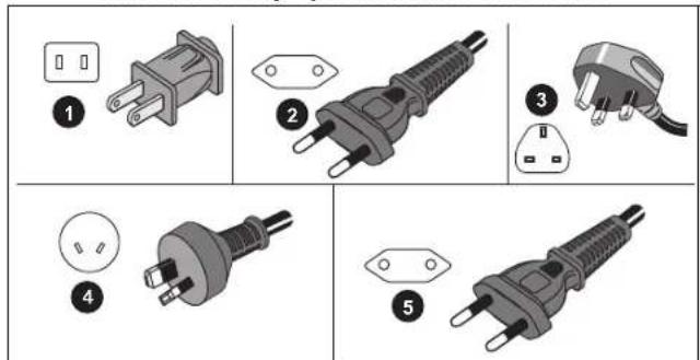
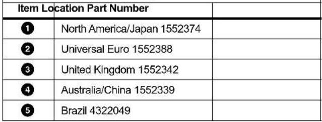 |
WiFi and WiFi/BLE-to-USB Adapter
The USB adapter enables the wireless connectivity of the Logger:
- Connection to the Fluke Connect™ smartphone app for easy asset management and data sharing.
• Data transfer to Energy Analyze Plus PC software. - Display and store data of up to 2 modules of the Fluke FC 3000 series together with the instrument data into logging sessions (requires WiFi/BLE or Bluetooth adapter feature, available with firmware version 2.0).
• Stream all data to the Fluke Connect Cloud - Manage assets and share data with the Fluke Connect smartphone app.
To install adapter sin the Logger:
- Remove the three screws in the battery door. See Figure 1.
- Remove the battery door.
- Remove the battery.
- Insert one or two WiFi/BLE adapters into the battery compartment with the serial number facing towards the front of the Logger and gently push until the adapter snaps into the USB socket. About 3.5 mm (0.14 in) of the metal shield should be visible.
- Connect the USB Bluetooth adapter on either the internal or external USB port.
Note If you have two dedicated USB adapters for WiFi and one adapter for Bluetooth Low Energy, always connect the WiFi adapters to the internal USB port.
-
Insert the battery. Be sure the battery decal is face down in the battery compartment.
-
Replace and fasten the battery door.
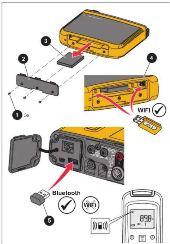
Figure 1. Adapter Installation
Magnet Hanger Kit
Use the Magnet Hanger Kit to hang the Product. See Figure 2.
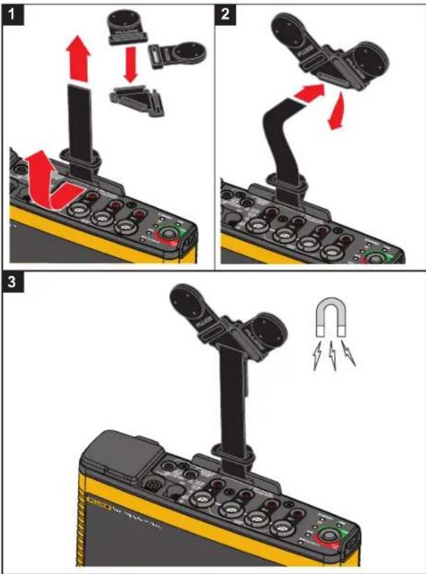
Figure 2. Magnet Hanger Kit
Caution
Always use two magnets to hang the Product.
Voltage Test Leads
Voltage test leads are four-core, flat, test leads that do not tangle and can be installed in tight spaces. On installations where the access to Neutral is out of reach with the three-phase test lead, use the black test lead to extend the Neutral lead.
For single phase measurements use the red and black test leads.
iFlexi Current Probe
The iFlexi Current Probe works on the Rogowski coil (R-coil) principle that is a toroid of wire used to measure an alternating current through a wire encircled by the toroid. See Figure 3.
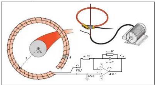
Figure 3. R-Coil Operation Principle
The R-coil has advantages over other types of current transformers:
- It is not a closed loop. The second terminal is passed back through the center of the toroid core (commonly a plastic or rubber tube) and connected along the first terminal. This allows the coil to be open-ended, flexible, and able to be wrapped around a live conductor without disturbing it.
- It has an air core rather than an iron core. It has a low inductance and can respond to fast-changing currents.
- Because it has no iron core to saturate, it is highly linear even when subjected to large currents, such as those used in electric power transmission or pulsed-power applications.
1742/1746/1748
Users Manual
A correctly formed R-coil, with equally spaced windings, is largely immune to electromagnetic interference.
Use the cable markers for easy identification of the four current probes. Apply the markers on both ends of the current probe cable. See Figure 4.
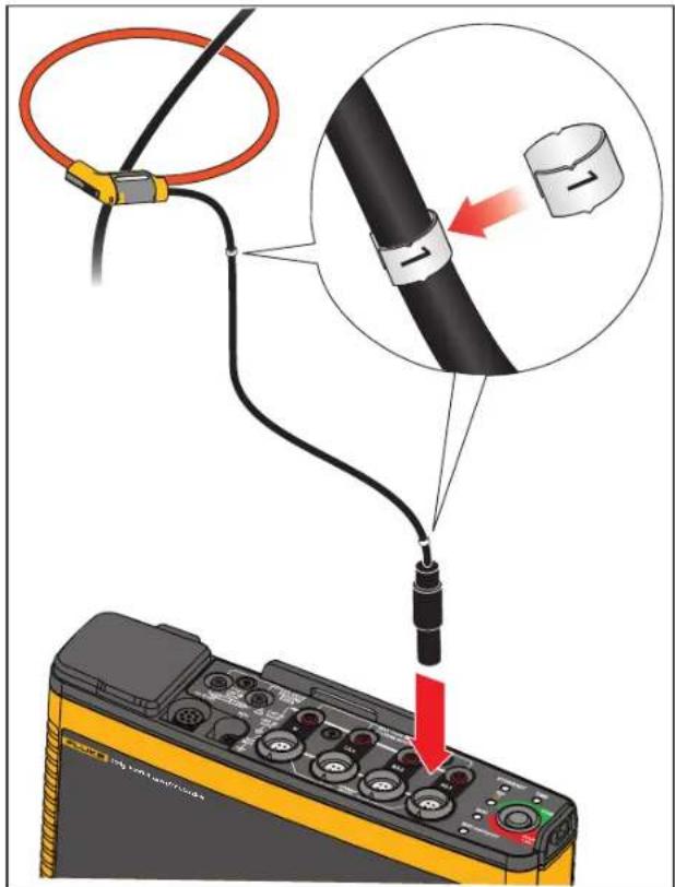
Figure 4. Test Leads with Color Coding
Storage
When not in use, keep the Logger in the protective storage bag/case. The bag/case has sufficient space for the Logger and all the accessories.
If the Logger is stored for an extended period of time or is not in use for a long time, you should charge the battery at least once every six months.
Accessories
Table 2 is a list of the accessories that are available and sold separately for the Product. The warranty on included accessories is 1 year. For the most up-to-date information on accessories, go to www.fluke.com.
Table 2. Accessories
| Part ID Description Part Number | ||
| 1742-6/UPGRADE 1742 to 1746 Upgrade | [1] | 4920964 |
| 1742-8/UPGRADE 1742 to 1748 Upgrade | [1] | 4920973 |
| 1746-8/UPGRADE 1746 to 1748 Upgrade | [1] | 4920986 |
| IEEE 519/REPORT Software License for IEEE 519 Reporting 4589748 | ||
| IP65 VOLT CONN IP65 Rated Voltage | Connector 4888191 | |
| I17XX-FLEX1.5KIP Fluke-17xx IP65 iFlexi 1.5 kA 24 in/60 cm 4921003 | ||
| I17XX-FLEX1.5KIP/3PK Fluke-17xx IP65 iFlexi 1.5 kA 24 in/60 cm, 3 pack 4921015 | ||
| I17XX-FLEX1.5KIP/4PK Fluke-17xx IP65 iFlexi 1.5 kA 24 in/60 cm, 4 pack 4921026 | ||
| I17XX-FLEX3KIP Fluke-17xx IP65 iFlexi 3 kA 24 in/60 cm | 4921032 | |
| I17XX-FLEX3KIP/3PK | Fluke-17xx IP65 iFlexi 3 kA 24 in/60 cm, 3 pack | 4921044 |
| I17XX-FLEX3KIP/4PK | Fluke-17xx IP65 iFlexi 3 kA 24 in/60 cm, 4 pack | 4921067 |
| I17XX-FLEX6KIP Fluke-17xx IP65 iFlexi 6 kA 36 in/90 cm | 4921071 | |
| I17XX-FLEX6KIP/3PK | Fluke-17xx iFlexi 6 kA 36 in/90 cm, 3 pack | 4921080 |
| I17XX-FLEX6KIP/4PK | Fluke-17xx iFlexi 6 kA 36 in/90 cm, 4 pack | 4921098 |
| I17XX-FLEX5M-EXT | Fluke-17xx iFlexi Extension Cable 5 m | 4921116 |
| FLUKE-174X GPS-REC | GPS Receiver Antenna | 4921133 |
| Fluke-PQ-Marker | Cable Marker Set 3 phase + N + PE | 5046009 |
| 174x-HANGER KIT | Magnet Hanger Kit | 4890129 |
| FLUKE-17XX AUX | Auxiliary Input Adapter for 17xx | 4717827 |
| MA-C8 | Wall Outlet Adapter | 4945842 |
| BP1730 | Battery Pack | 4389436 |
| Test Leads 0.18 m | 0.18 m (7 in) Test Lead Set, blue | 5016873 |
| Part ID | Description | Part Number |
| Test Leads 2 m with Alligator Clips | 2 m (6.6 ft) Test Lead Set + 2x Alligator Clips, blue | 5020006 |
| 3PHVL-17xx 2 m Voltage Test Lead 3-phase + N, 2 m (79 in) 5014802 | ||
| 3PHVL-17xx 5 m Voltage Test Lead 3-phase + N, 5 m (197 in) 5014816 | ||
| i40s-EL 40 A (single) Current Clamp 4637396 | ||
| i40s-EL/3PK Set of 3 Current Clamps, 40 A 4637409 | ||
| i400s-EL 400 A (single) Current Clamp 4637396 | ||
| i400s-EL/3PK Set of 3 Current Clamps, 400 A 4637409 | ||
| PQ400 | Power Quality Window | 4920947 |
| PQ-400/B | Power Quality Window, Basic | 5075807 |
| 17xx AUX Input Adapter | Auxiliary Input Adapter for up to 2 DC voltages (0 V to 10 V and 0 V to 1000 V) | 4717827 |
| Fused Test Probe Set | Set of 4 Test Probes, three phase, AC285, 3x red, 1x black | 4954311 |
| MP1-3R Magnet Probe Set | Set of 4 Magnet Probes for 4 mm banana plugs, 3x red, 1x black | 4944790 |
| C17xx | Soft Case | 4637381 |
| FLK-WIFI/BLE | WiFi/BLE to USB Adapter (check with your sales representative for availability) | 4591273 |
| [1] Upgrade includes hardware items included with model upgrade (see Licensed Features) | ||
User Interface
Table 3 is a list of the controls and connectors.
Table 3. Connector Panel
| Item Description Item Description | |||
| ① | Ethernet | ⑧ | LED for WiFi |
| ② | Power Supply Input 100-500 V 50/60 Hz 50 VA | ⑨ | LED for WiFi Hotspot |
| ③ | Voltage measurement inputs (3 phases + N) | ⑩ | Current measurement inputs (3 phases + N) |
| ④ | LED for Ethernet | ⑪ | Aux connector |
| ⑤ | LED for Time | ⑫ | I/O connector for GPS Receiver |
| ⑥ | Power On/Off | ⑬ | USB connector (for data download and firmware update) |
| ⑦ | LED for Fluke Connect™ | ⑭ | Mini-USB connector (for data download) |
Power Supply
The Logger has options for power source:
- mains
- measurement line
- battery
The Start/Stop LED shows the status. See Table 4 for more information.
Mains Power Source
- Attach the mains adapter MA-C8 to both power supply inputs of the Logger. See Figure 5.
- Connect the power cord into the adapter.
- Plug the power cord to a wall outlet.
The Logger automatically turns on and is ready to use in <30 seconds.
- Push and hold >3 seconds to turn off the Logger. Push the Start/Stop button to turn on again.
The Logger needs to be in the Idle state to turn off. A non-flashing Start/Stop LED indicates the Idle state.
Note
Remove the power cord from the MA-C8 adapter before you remove the adapter from the Logger.
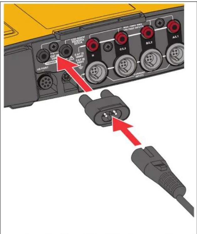
Figure 5. Power Supply
Measurement Line Power Source
Caution
To prevent damage to the product, make sure the measured voltage does not exceed the input rating of the power supply.
Warning
To prevent injury, do not touch the metal parts of one test lead when the other is still connected to hazardous voltage.
- Attach the power supply to the Logger.
- Move the slide-cover on the power supply to access the safety sockets.
- Connect the short test leads (see Figure 6) with the power supply inputs. Make sure to use the non-stackable plugs. The test leads are rated for measurement/overvoltage CAT III 1000 V and CAT IV 600 V.
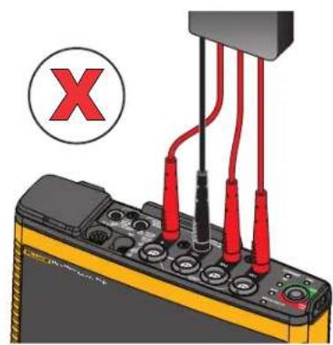
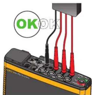
Figure 6. Measurement Connection to the Logger
-
Connect the test leads with the voltage measurement inputs:
-
Connect A/L1 with one input of the power supply.
- Connect N with the second input of the power supply. See Figure 7.
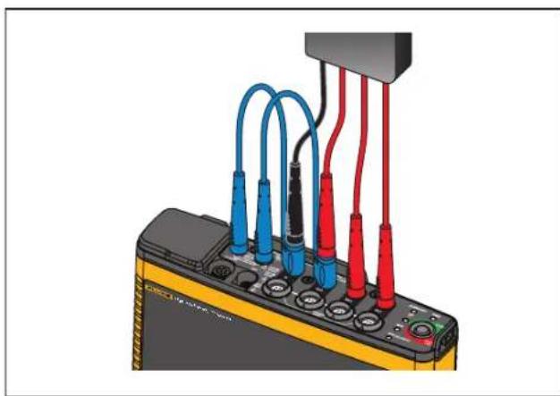
natural_image
Close-up of a black electronic device with multiple colored test probes connected to a power outlet (no visible text or symbols)Figure 7. Measurement with Neutral Voltage and Instrument Power Supply
OR
- Connect A/L1 with one input of the power supply.
-
Connect B/L2 with the second input of the power supply. See Figure 8.
-
Use the short fan out of the Voltage Test Lead, 3-phase + N. Plug the connector A/L1 into the socket A/L1 of the voltage measurement inputs of the Logger. Repeat this with B/L2, C/L3 and N.
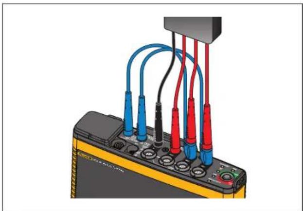
natural_image
Illustration of an electronic testing device with multiple colored test probes connected to a terminal block (no visible text or symbols)Figure 8. Measurement without Neutral Voltage and Instrument Power Supply
Note
You must locate and connect an alternate power source to the instrument if the voltage to measure is <100 V or >500 V. Use the set of 2 m test leads (see Table 6) or the supplied power cord.
- Connect the voltage inputs to the test points.
The Logger automatically turns on and is ready to use in <30 seconds.
Battery Power Source
The Logger uses an internal rechargeable Lithium-ion battery. The battery automatically charges when the Logger is connected to mains power. Fully charge the battery before first use. Afterwards, charge the battery when the Start/Stop LED or the battery status in the remote control software indicates that the power is low.
Note
The Logger continues to charge when turned off and connected to mains power.
Caution
To prevent damage to the Product:
- Do not leave batteries unused for extended periods of time, either in the product or in storage.
- When a battery has not been used for six months, check the charge status and charge the battery as appropriate.
- Clean battery packs and contacts with a a clean, dry cloth.
- Battery packs must be charged before use.
- After extended storage, it can be necessary to charge and discharge a battery pack to obtain maximum performance.
- Dispose of the batteries properly.
Push the Start/Stop button. The Logger turns on and is ready to use in <30 seconds.
Start/Stop Button and Status LEDs
The Start/Stop button has a dual use to turn on and turn off the Logger as well as to start and stop a logging session.
LEDs on the connector panel show the status. See Table 4 for more information about the LED indicators.
To power on:
- Push the Start/Stop button on the Logger.
- Watch the Start/Stop button LED:
• White indicates the startup mode.
• Green indicates the Logger is ready to use.
- Amber indicates important information or a warning. Check the status with the remote control tool, Energy Analyze Plus.
During the startup of the Logger, you can reset the Logger to factory defaults. See Reset to Factory Defaults for more information.
To power off:
- Push and hold the Start/Stop button for >3 s.
- Watch the Start/Stop button LED:
• White indicates the shutdown mode.
- Flashing indicates that an active logging session is in progress.
You cannot turn off the Logger while an active logging session is in progress. Stop the logging session before you power off the Logger.
To start or stop a logging session:
- After you turn on the Logger and it is ready use, push the Start/Stop button on the Logger.
- Start a new logging session with the last-known settings.
The flashing Start/Stop LED indicates that an active logging session is in progress.
- Push and hold the Start/Stop button for >3 s to stop the logging session.
Note
To stop a logging session and turn off the Logger, push and hold the Start/Stop button >3 s twice.
Table 4. LED Indicators
| LED Color Status Note | |||
| Start/Stop | green | No user information or warning available.Logger power from mains.No connection errors detected. | |
| amber | Information or warning available.Possible reasons: Logger power from battery or circuit connection error detected. | Check the actual status with Energy Analyze Plus if shows | |
| white | Steady: start/stop | Do not turn off the Logger or remove the USB drive | |
| Flashing: file operation in progress | |||
| Time | green Time synchronization status is OK | ||
| off External time synchronization is not in use | |||
| red Time synchronization source not available | Check the time synchronization source and configuration of the Logger | ||
| Ethernet | green | Ethernet link detected and IP address is assigned | The LED flashes during the IP address assignment |
| blue Connection to the Fluke Connect Cloud is established | |||
| Fluke Connect blue | Flashing: Receiving data from all configured FC modules | Rapid flashing indicates loss of connection to one or all FC modules | |
| WiFi | green | Steady: Connection to a WiFi access point established | |
| Flashing: Configured WiFi access point is out of range or the connection can not be established | Check the WiFi access point configuration of the Logger.Reduce the distance between the Logger and the WiFi access point.Verify that the passphrase is correct. | ||
| blue Connection to the Fluke Connect cloud established | |||
| WiFi Hotspot | green The | Logger WiFi Hotspot is active | |
| blue A client is connected to the WiFi Hotspot | |||
Energy Analyze Plus Software
Purchase of the Logger includes Fluke Energy Analyze Plus software. Use the software to do many tasks from a computer:
- Configure the Logger.
- Set up a new logging session.
- Download campaign results for further processing and archiving.
- Analyze energy or load profiles, including zoom-in and zoom-out on details.
• Analyze voltage and current harmonics. - Review the voltage and current events that occur during the campaign.
- Add comments, annotations, pictures, and other supplementary information to campaign data.
- Overlay data from different campaigns to identify and document changes.
• Create a report from the analysis you performed. - Export measurement results for further processing using a third party tool.
System Requirements
The computer hardware requirements for the software are:
- Free Hard Disk space minimum 200 MB, >10 GB (for measurement data) recommended. Additionally, Energy Analyze can use up to 1 % of the disk size for internal logs. Internal log data is not shared with Fluke or any third party unless allowed by the user.
- Installed Memory:
- 1 GB minimum, >2 GB recommended for 32-bit systems
- ≥4 GB recommended for 64-bit systems
• Monitor, 1280 x 1024 (@4:3) or 1440 x 900 (@16:10), wide-screen (16:10) or higher resolution recommended
- Ethernet, WiFi, or USB ports
• Windows 7 32/64-bit, Windows 8 32/64-bit.
Note
Windows 7 Starter edition and Windows 8 RT are not supported. Energy Analyze Plus also works on Windows XP systems, but is not specifically tested because XP support is discontinued.
How to Connect to Energy Analyze Plus
The Logger supports several interfaces to connect to the PC:
- USB cable
- Ethernet
• WiFi - direct connection
• WiFi - connection to infrastructure
Note
WiFi connectivity requires that a radio certification for the WiFi or WiFi/BLE adapter is available for your country. Check www.fluke.com for availability.
After one or more connections are established, Energy Analyze Plus software shows the Logger in the list of found devices. Choose the Logger to setup and/or download measurement data from.
USB Cable
To connect the PC to the Logger:
- Turn on the computer and the Logger.
-
Make sure Energy Analyze Plus Software is installed. The software installation also installs the required drivers.
-
Connect the USB cable to the USB ports of the computer and the Logger. See Figure 9.
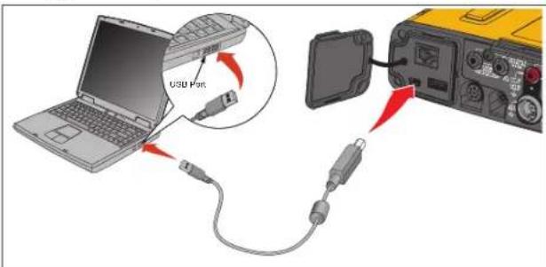
Figure 9. Power Logger to PC Connections
- The USB cable connection uses a network communication over USB (Remote NDIS network) with Internet Protocol IPv6. When you connect the Logger with the RNDIS network interface, a serial port "USB Serial Port (COMx)" appears in Windows device manager. This serial port is for production and service/calibration purposes only.
Note
Make sure IPv6 is enabled on your Windows system.
Ethernet
Use a commercially available Cat 5 or higher Ethernet patch cable to connect the Logger to your LAN (local area network). A communication over Ethernet requires that each device has a unique IP address. Two options exist: Either a device obtains an address from a DHCP server or the device uses a static, user-configured address.
The default setting of the Logger is to obtain an IP address from a DHCP server automatically. The Ethernet LED (4) flashes when a link has been established but no IP address is assigned. Once the Logger IP address is assigned, the LED is steady green. Navigate to the Network Configuration of the remote control client to identify the assigned IP address, subnet mask and gateway.
Optionally, you can configure a static IP address, subnet mask, and gateway. Be sure that the LAN supports static address assignment. A connection to the device is only possible if the IP address range of the computer matches with the IP address of the Logger. The range is specified with the subnet mask. For example, a Logger with an IP address 192.168.0.100 and a subnet mask of 255.255.255.0 is accessed by a PC only when its IP address is any address between 192.168.0.1 and 192.168.0.254 except the Logger address.
The Logger allows a Ethernet point-to-point connection between the Logger and a PC. The Logger has Auto-MDI-X support to switch automatically between 1:1 for a device-to-LAN connection and cross-over mode required for a device-to-device connection. A cross-over cable is not required. The Logger and PC self-assign IP addresses in the range of 169.254.x.x automatically after the timeout to receive an IP address from a DHCP server expires.
Note
During the typical timeout of 1 minute, Windows shows the status "Identifying" in the network status. Windows may show an exclamation mark in the network status icon indicating that the connection does not provide Internet access. This is normal.
The Logger communicates with the Fluke Energy Analyze Plus software on following ports:
| Type Port Number | |
| TCP 80 (HTTP) | |
| TCP 443 (HTTPS) | |
| TCP 18571 | |
| UDP 123 (NTP) | |
| UDP 18571 |
The software installer for Energy Analyze Plus automatically adds exceptions to the Windows firewall. If a third party firewall is used, add the ports and the application fea.exe to the exception list.
WiFi Direct Connect
With the built in USB WiFi Adapter you can wirelessly control the Logger and download measurement data to the Energy Analyze Plus software. The WiFi direct connection uses WPA2-PSK (pre-shared key) with AES encryption.
To make a WiFi connection:
- If not already, enable the WiFi Hotspot on the Logger.
A green WiFi Hotspot LED indicates that the connection is active. If the LED is off, the WiFi/BLE-to-USB is not installed. See WiFi and WiFi/BLE-to-USB Adapter.
-
On the client, go to the list of available WiFi networks and look for a network with the name: "Fluke174x
" for example: "Fluke1746<12345678>. -
At the prompt for WiFi passphrase, enter fluketools.
Depending on the operating system of the client, the passphrase is also called Security Key, Password, or similar. After a few seconds, the connection is established.
A blue WiFi Hotspot LED indicates an established connection with a client.
Note
Windows checks if the WiFi connection enables an Internet connection. This may take up to one minute until the Logger is accessible. A missing Internet connection is indicated by "No Internet" in Windows 10 or with an exclamation mark in the WiFi icon on Windows 7. This is normal since the Logger is not a gateway to the Internet.
WiFi to Infrastructure
With a second WiFi-to-USB adapter the Logger can connect to a WiFi access point. No security and WPA2-PSK security is supported. This connection requires a DHCP service running in the access point to assign IP addresses automatically.
Note
This feature requires the WiFi-Infrastructure license.
To connect to an access point:
-
Select the access point from the list of found SSID (Service Set Identifier - name of the access point) or enter the name of a hidden SSID.
-
Enter the passphrase (8 to 63 characters) of the access point.
A blinking green WiFi LED (8) shows while the Logger tries to establish a connection to the configured access point. This takes usually a few seconds. A solid green LED indicates the connection is ready. Consult the remote control tool for a field strength indication of the access point. If the WiFi symbol shows only one to two green bars, the WiFi connection might be unreliably. Reasons for a permanently blinking LED or blinking after the LED was solid green already:
- No access point configured.
- The configured access point is out of reach.
- The password is incorrect.
In all cases, see the remote control tool for more details.
First-time Use/Setup Wizard
Before you start:
- Install Energy Analyze Plus software on your PC.
- Attach the cable marker clips to both sides of the current probe cables. Depending the region, use the markers A, B, C, N or 1, 2, 3, N.
- Install the WiFi or WiFi/BLE-to-USB adapter.
See WiFi and WiFi/BLE-to-USB Adapter for more information. - Connect the Logger to mains power. The Logger starts in <30 seconds and is ready when the Start/Stop LED is either green or amber.
The Logger is now ready for the first measurements or energy study.
First Measurements
At the energy study site, look at the information in the panel and the rating plates on the machines. Based on knowledge of the electrical supply in the facility, determine the configuration.
To set up the Logger:
- Connect the Logger to mains power.
Note
See Measurement Line Power Source if you want to power the Logger from the measurement line.
The Logger starts.
- Plug the voltage test leads into the Logger.
- Connect the Thin-Flexi current probes to the Logger:
- Phase A/L1 current probe into the phase A/L1 input jack
- Phase B/L2 current probe into the phase B/L2 input jack
- Phase C/L3 current probe into the phase C/L3 input jack
- N (neutral current) probe into the N input jack
- Apply the iFlex Probes to the wires in the electrical panel. Make sure the arrow on the probe points to the load.
- Connect the voltage test leads to neutral, phase A/L1, phase B/L2, and phase C/L3.
To set up the software:
- Make sure the Energy Analyze Plus software is installed and available on your PC. If not, see Energy Analyze Plus Software.
- If not already, enable the WiFi Hotspot on the Logger.
A green WiFi Hotspot LED indicates that the WiFi Hotspot is enabled. If this LED is off, connect the USB cable. See Figure 9 and go to Step 5. - On your PC, go to WiFi settings and select the WiFi network, for example, Fluke1748<39614805>.
- At the prompt for WiFi passphrase, also called security key, enter fluketools.
-
In Energy Analyze Plus, select Instrument Setup.
-
Select the device from the drop-down list that shows all found devices.
- Enter the user credentials to permit access to the device configuration. The factory defaults are:
User name: admin
Password:
- Verify the logger date and time and synchronize to the PC clock if necessary.
- Confirm the study type and the wiring configuration is correct. Use the wiring diagram for guidance on the voltage test lead and current probe connections.
- Confirm the nominal voltage and frequency. For most applications, the current range is set to Auto and the voltage and current ranges are 1:1.
-
Go to Connection Verification to:
-
check the voltage, current, and power readings
- correct the phase rotation, phase mapping, and polarity of current probes
Note
Most installations use a clockwise rotation.
To start measurements:
- Review and adjust the limit setting for the Power Quality events, such as dips, swells, interruptions, rapid voltage changes, waveform deviation, mains signaling, and inrush current.
-
Configure the logging session. A typical setup is:
-
1 week duration
- 1 minute for trend interval
- 5 minutes for demand interval
Note
Power Quality data is stored at intervals of 150/180 cycles and 10 min.
- Push the on the Start/Stop button on the Logger.
- Download the measurement during and after the logging session with Energy Analyze Plus.
- Click Download Data and copy the logging session from the Logger to the PC.
- Open the session and view the measurement data.
For more information about how to use Energy Analyze Plus, see the software for online help.
Instrument and Logging Setup
Use Energy Analyze Plus software on your PC to manage the setup, configuration, and connection verification of the Logger.
Measurement Configuration
The measurement configuration includes:
- Study Type
- Topology
• Nominal Voltage and Nominal Frequency - Current Range
• Scale Factors for External PTs or CTs
• Harmonics Calculations
• Event Configuration - Dip, Swell, and Interruptions
- Rapid Voltage Changes
- Waveform Deviation
- Main Signaling Voltage
- Inrush Current
Connection Verification
• View live data
• Auto-correct connection errors
- Swap phase channels
- Invert current probes
Logging Setup
• Edit the name of the logging session
- Add a description
- Set the averaging interval for trend and demand data
• Set start and end date and time
- Stop an active session
Instrument Setup
- Configure an instrument name
- Set user credentials to access the Logger
- Select time synchronization source
- Ethernet and WiFi configuration
- Update firmware
• Install license
• Download service data - Reset to factory defaults
Measurement Configuration
Study Type
Depending on the application, select either Load Study or Energy Study.
- Energy Study: Select this study type when voltage measurements for a power quality assessment and power and energy values that include active power (W) and PF are required.
- Load Study: For convenience, some applications require you to measure only the current that makes the connection to the point to measure.
Typical applications are:
- Verify the circuit capacity before adding additional load.
- Identify situations where the allowable load can be exceeded.
Optionally, a nominal voltage can be configured to get pseudo-apparent power readings.
Topology (Distribution System)
Select the appropriate system. Examples of these diagrams are shown on the following pages.
Single Phase
Example: Branch circuit at an outlet.
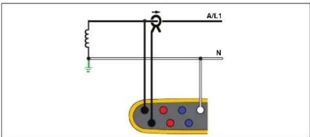
Energy Study
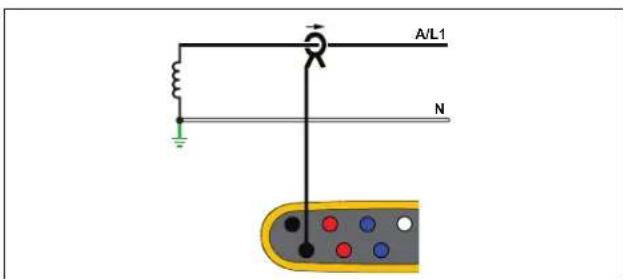
Load Study (no voltage measurement)
Single Phase IT
The Logger has a galvanic isolation between the voltage inputs and ground based signals like USB and mains input.
Example: Used in Norway and in some hospitals. This would be the connection at a branch circuit.
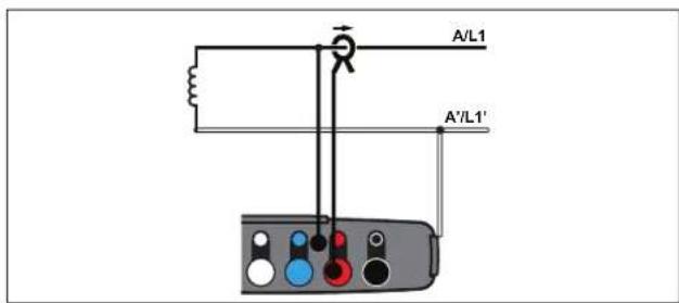
Energy Study
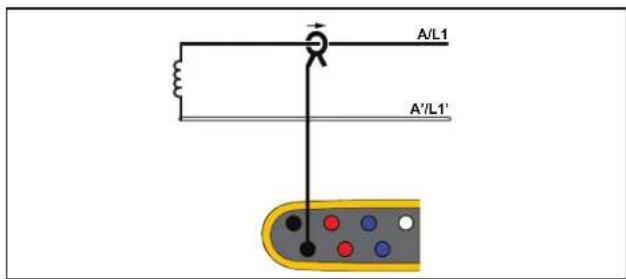
Load Study (no voltage measurement)
Split Phase
Example: A North American residential installation at the service entrance.
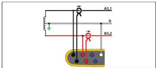
Energy Study
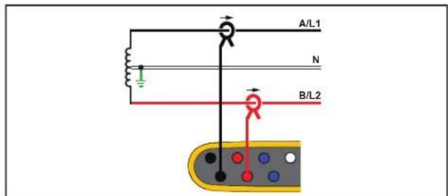
Load Study (no voltage measurement)
1742/1746/1748
Users Manual
3-Φ Wye
Example: Also called "Star" or four-wire connection. Typical commercial building power.
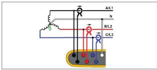
Energy Study
3-Φ Wye IT
The Logger has a galvanic isolation between the voltage inputs and ground based signals like USB and mains input.
Example: Industrial power in countries that use the IT (Isolated Terra) system, such as Norway.
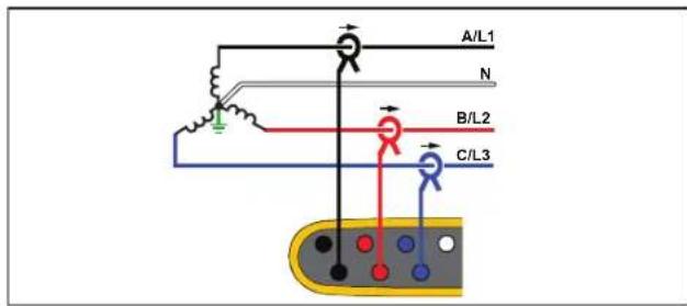
Load Study (no voltage measurement)
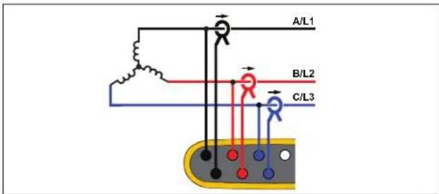
Energy Study
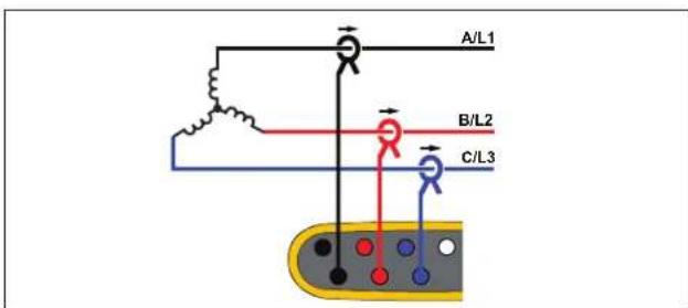
Load Study (no voltage measurement)
3-Φ Wye Balanced
Example: For symmetrical loads like motors the connection can be simplified by measuring only one phase and assuming the same voltages/currents on the other phases. As an option, you can measure harmonics with a current probe on the neutral line.
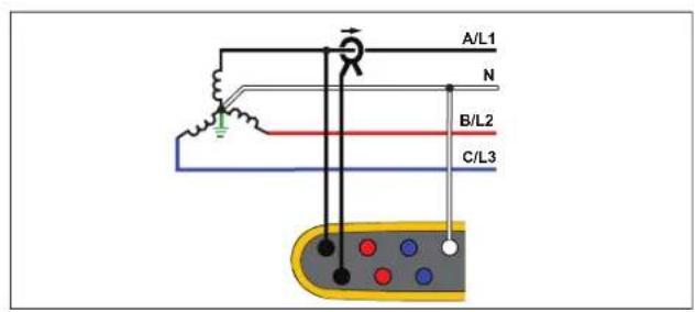
Energy Study
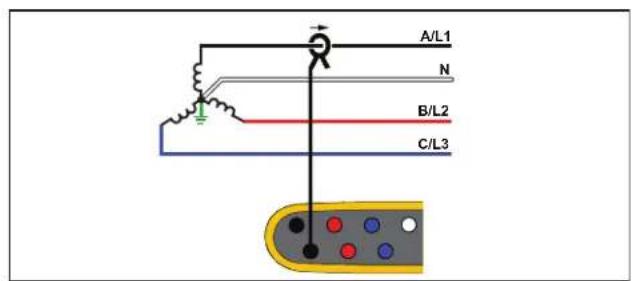
Load Study (no voltage measurement)
3-Φ Delta
Example: Often found in industrial settings where electric motors are used.
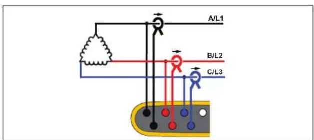
Energy Study
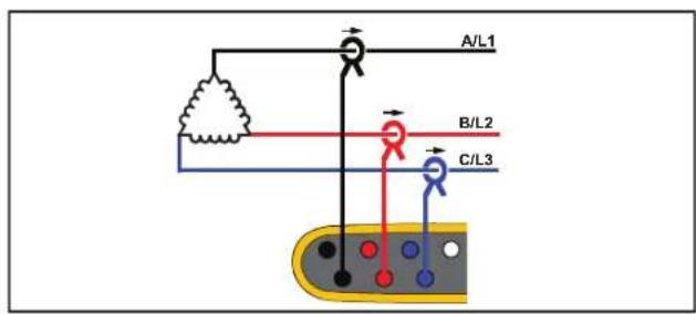
Load Study (no voltage measurement)
2 Element Delta (Aron/Blondel)
Example: Blondel or Aron connection, simplifies the connection by the use of only two current sensors.
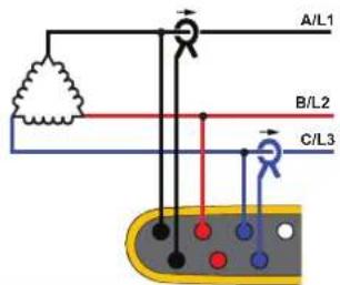
Energy Study
3-Φ Delta Open Leg
Example: A variant of power transformer winding type.
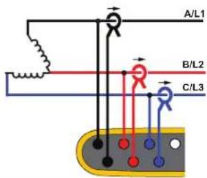
Energy Study
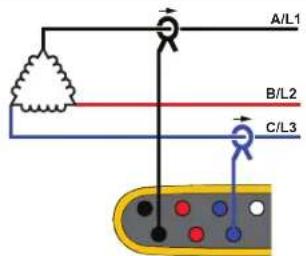
Load Study (no voltage measurement)
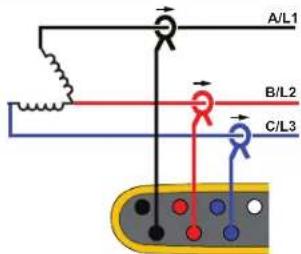
Load Study (no voltage measurement)
Note
Make sure that the current arrow on the sensor is directed towards the load to provide positive power values. The current sensor direction can be corrected digitally in the Connection Verification screen.
3-Φ High Leg Delta
Example: This topology is used to provide an additional voltage that is half the phase to phase voltage.
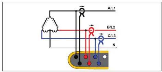
Energy Study
3-Φ Delta Balanced
Example: For symmetrical loads like motors, the connection is simplified with only one phase measurement and assuming the same voltages/currents on the other phases.
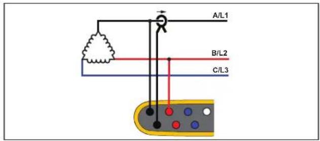
Energy Study
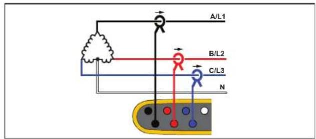
Load Study (no voltage measurement)
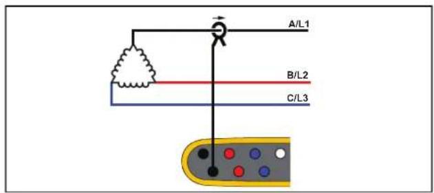
Load Study (no voltage measurement)
Nominal Voltage
Select a nominal voltage from the list. If a voltage is not shown in the list, enter a custom voltage. On energy studies, the nominal voltage is required to determine the limits for dips, swells, and interruptions.
The nominal voltage on load studies is used to calculate the pseudo apparent power:
nominal voltage x measured current
Nominal Frequency
Set the nominal frequency to be the same as the power line frequency, 50 Hz or 60 Hz.
Voltage Ratio (only in energy studies)
Configure a ratio factor for the voltage inputs when a potential transformer (PT) is in series with the voltage connections such as when you want to monitor a medium-voltage network. The default value is 1:1.
Current Range
Configure the current range of the attached sensor:
- Auto
When set to Auto, the current range is set automatically and depends on the measured current. - Low Range
Low Range is 1/10 of the nominal range of the attached current sensor. For example, the low range of an iFlex1500-12 is 150 A.
- High Range
High Range is the nominal range of the attached current sensor. For example, 1500 A is the nominal range on an iFlex1500-12.
Note
Set the current range to Auto when you are not sure about the maximum current during the logging session. A specific application can require you to set the current range to a fixed range rather than Auto. This can occur because the Auto range is not gapless and may lose too much information in the case of a highly fluctuating current.
Current Ratio
Configure a ratio factor for the current sensors when a current transducer (CT) is used to measure the much higher level on the primary side at a substation or step-down transformer that has a built-in metering current transformer.
Use the current ratio to increase the sensitivity of the iFlex sensor. Wrap the iFlex sensor around the primary conductor, for example 2X, and enter a ratio factor of 0.5:1 to get correct readings. The default value is 1:1.
Harmonics Calculation Method
Select the harmonic calculation method to apply according to IEC 61000-4-7. The Logger applies a FFT (Fast Fourier Transformation) every 10/12 cycles (typical 200 ms), that delivers spectral components (bins) every 5 Hz from dc up to 12 fs. fs is the sample frequency of the A/D converter, for example, 10.24 kHz. The standard allows three different ways to calculate the harmonics from these 5 Hz components: Harmonic Components, Harmonic Sub-Groups, and Harmonic Groups.
Overview.
| Harmonics Interharmonics | ||
| Harmonic Components(required for measurements according to certain standards, such as IEEE519 or IEC 61000-3-12) | 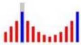 RMS value of a single 5 Hz component RMS value of a single 5 Hz component | 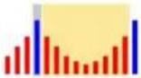 RMS value of all bins between two harmonics RMS value of all bins between two harmonics |
| Sub-Grouped Harmonics (default)(for IEC 61000-4-30 compliant measurements, such as EN50160) | 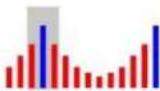 RMS value of the harmonic frequency and adjacent bins RMS value of the harmonic frequency and adjacent bins | 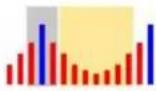 RMS value of all bins between two harmonics RMS value of all bins between two harmonics |
| Grouped Harmonics | 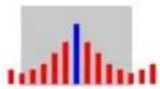 RMS value of the harmonic frequency and 1⁄2 of the interharmonic spectrum to both sides RMS value of the harmonic frequency and 1⁄2 of the interharmonic spectrum to both sides | not available |
Harmonic Components. The fundamental h01 and harmonics h02 ... h50 are represented by the bin of the harmonic frequency.
The interharmonics ih01 ... ih50 are calculated from all spectral components between two consecutive harmonic frequencies.
Examples:
- On a 60 Hz system, the h02 at 120 Hz is represented by the bin no. 24 (120 Hz / 5 Hz = 24).
- The harmonic h03 at 180Hz is represented by the bin no. 36 (180 Hz / 5 Hz = 36).
- The interharmonic ih02 is represented by the bins no. 25 – 35 (125 Hz ... 175 Hz).
Select Harmonic Components for measurements according to standards that require the harmonics components measurement according to IEC 61000-4-7 or IEC 61000-3-12.
Sub-Grouped Harmonics. The fundamental h01 and harmonics h02 ... h50 are the RMS average of the bin of the harmonic frequency and one adjacent bin to each side.
The interharmonics ih01 ... ih50 are composed of the remaining seven bins for 50Hz systems or nine bins for 60Hz systems between two adjacent harmonics.
Examples:
- Select Harmonic Components for measurements according to standards that require the harmonics components measurement according to IEC 61000-4-7, for example IEEE 519 or IEC 61000-3-12.
- The harmonic h03 at 180 Hz is represented by the bin no. 35, 36, and 37 (180 Hz / 5 Hz = 36).
- The interharmonic ih02 is represented by the bins no. 26 – 34 (130 Hz ... 175 Hz).
Note
Many power quality standards, such as EN 50160 and GOST 33073, refer to IEC 61000-4-30 Class A measurement methods that require Harmonic Sub-Groups.
Grouped Harmonics.
The fundamental h01 and harmonics h02 ... h50 are the RMS average of the bin of the harmonic frequency and half of the bins between two adjacent harmonic frequencies to both sides. The center bin between two harmonic frequencies is included in both harmonics with 50 %. Bins between h01 and h02 are not included.
Interharmonics are not available when the selection is grouped harmonics.
Examples:
- On a 60 Hz system, the harmonic h03 at 180 Hz is represented by the bins 31-35, 36, 37-41, 50 % of bin no. 30 and 50 % of bin no. 42
- The harmonic h04 at 240 Hz is represented by the bin no. 43-47, 48, 49-53, 50 % of bin no. 42 and 50 % of bin no. 54
The advantage of the measurements using grouped harmonics is to cover the entire spectrum without the need to store memory-consuming interharmonics. Make sure to apply this measurement only if the applicable standard requires this measurement method.
Flicker
The Logger supports the assessment of Flicker severity according to IEC 61000-4-15.
Select the lamp-model voltage applied within the Flicker measurement algorithm. Make sure the lamp model selection matches the Nominal Voltage setting unless the measurement includes the use of voltage transducers. In this case make sure to select a lamp-model voltage that matches the Nominal Voltage definition of the associated low voltage grid.
Configuration of Events
Voltage Dips
On single-phase systems, a voltage dip begins when the voltage falls below the dip threshold, and ends when the voltage is equal to or above the dip threshold plus the hysteresis voltage. See Figure 10.
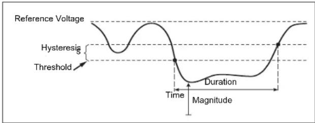
Figure 10. Characteristics of a Voltage Dip
On polyphase systems, a dip begins when the voltage of one or more channels is below the dip threshold and ends when the voltage on all measured channels is equal to or above the dip threshold plus the hysteresis voltage.
Choose nominal or sliding reference voltage. A sliding reference voltage uses measured values filtered with a 1-minute time constant and applies usually only for medium and high voltage systems.
Parameters to configure:
- Limit
The threshold limit value is defined as % of nominal voltage or sliding reference. The default value is 90 % and the hysteresis is 2 %.
Voltage Swells
On single-phase systems, a swell begins when the voltage rises above the swell threshold, and ends when the voltage is equal to or below the swell threshold minus the hysteresis voltage. See Figure 11.
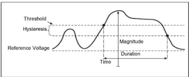
Figure 11. Characteristics of a Voltage Swell
On polyphase systems, a swell begins when the voltage of one or more channels is above the swell threshold and ends when the voltage on all measured channels is equal to or below the swell threshold minus the hysteresis voltage.
Choose nominal or sliding reference voltage. A sliding reference voltage uses measured values filtered with a 1-minute time constant and applies usually only for medium and high voltage systems.
Parameters to configure:
- Limit
The threshold limit value is defined as % of nominal voltage or sliding reference. The default value is 110 % and the hysteresis is 2 %.
Voltage Interruptions
On single-phase systems, a voltage interruption begins when the voltage falls below the voltage interruption threshold and ends when the value is equal to or greater than the voltage interruption threshold plus the hysteresis. See Figure 12.
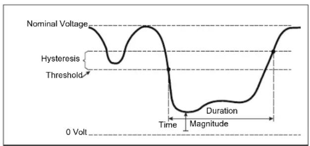
Figure 12. Characteristics of a Voltage Interruption
On polyphase systems, a voltage interruption begins when the voltages of all channels fall below the voltage interruption threshold and ends when the voltage on any one channel is equal to, or greater than, the voltage interruption threshold plus the hysteresis.
Note
On polyphase systems, the event is still classified as a dip when the voltage of only one or two phases falls below the interruption limit.
Parameters to configure:
- Limit
The threshold limit value is defined as % of nominal voltage. The default value is 5 % and the hysteresis is 2 %.
Rapid Voltage Changes
Rapid voltage changes (RVC) are quick transitions of the RMS voltage between two steady states. Rapid voltage changes are captured based on RVC threshold. RVC threshold are set as percentage of the nominal voltage and the threshold level is calculated over the preceding 100/120 U_rms(1/2) values. (100/120 is defined as 100 values for 50 Hz nominal or 120 values for 60 Hz nominal.) An RVC Event is detected when the arithmetic mean of 100/120 U_rms(1/2) values falls outside the an RVC threshold. When a voltage change crosses the dip or swell thresholds, it is considered a dip or swell and not a rapid voltage change. The event list shows the voltage step, transition time, and Vmax. See Figure 13.
Parameters to configure:
- Trigger on/off
- Limit
The voltage Threshold limit value is defined as % of nominal voltage. The values is typically in the range of 1 % to 6 %. The RVC hysteresis shall be less than the RVC threshold and is typically 50 % of the RVC.
Waveform Deviation
The Waveform Deviation trigger monitors the differences in the waveforms of consecutive voltage cycles. Each sample magnitude of the last cycle is compared with the sample magnitude of the actual cycle. The trigger starts when the difference exceeds the configured limit and ends when the difference is lower than the threshold minus the hysteresis. If a waveform deviation triggers starts within one second after the previous waveform deviation trigger ended, it is combined to one event.
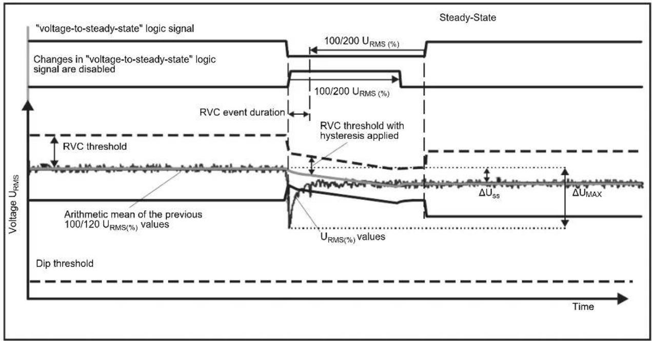
Figure 13. Rapid Voltage Change Characteristics
This trigger is a general-purpose trigger that detects non-stationary phenomena and is perfectly suitable for all kinds of disturbance analysis and troubleshooting, because most of the power quality problems result in a sudden change of the waveform. From the recorded waveforms, in most cases the root-cause of distortions can be identified: Switching of capacitor banks, commutation distortions, and oscillations on the mains supply. In addition, ground shorts in the medium voltage systems with their typical significant waveforms can be identified. See Figure 14.
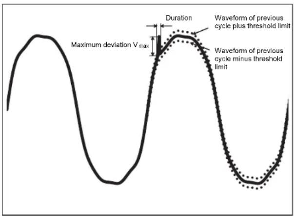
Figure 14. Waveform Deviation
Parameters to configure:
- Trigger on/off
- Limit
The voltage threshold limit is the maximum deviation of the sample magnitude of the actual cycle to the magnitude of the previous cycle in % of nominal voltage.
Recommendation of values depending on the required trigger sensitivity:
Power distribution systems can carry control signals to remotely switch on and off appliances (also known as ripple control). The control signals are present only at the moments that a remote appliance has to be controlled. The Mains Signaling trigger can capture the occurrence (signal level) of control signals with 2 different frequencies.
Parameters to configure:
- Trigger on/off
- Mains Signaling Voltage (MSV) frequency 1 and MSV frequency 2 in Hz
• Frequency range is 100 Hz up to 3000 Hz - Limit
The voltage threshold limit value is defined as % of nominal voltage. The value is typically in the range of 1 % to 5 %.
- Recording time
The event triggers a 10/12 cycle recording of up to 120s.
Inrush Current
Inrush currents are surge currents that occur when a large or low-impedance load comes on line. Normally the current will stabilize after some time when the load has reached normal working condition. For example, the start-up current in induction motors can be 10x the normal working current. See Figure 15. The inrush current begins when the 1/2-cycle RMS current rises above the inrush threshold, and ends when the 1/2-cycle RMS current is equal to or below the inrush threshold minus the hysteresis value. In the event table, the extreme value is the highest 1/2-cycle RMS value of the event.
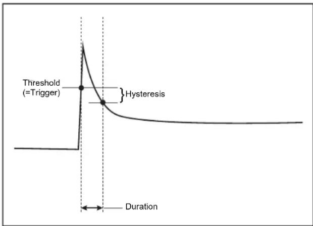
Figure 15. Inrush Characteristics
Parameters to configure:
- Trigger on/off
- Limit
The current threshold limit is the 12 cycle RMS value in A. A signal exceeding this limit triggers the event.
Logging Session Setup
Name. The Logger auto-generates a file name with the format ES.xxx or LS.xxx. ES ... Energy Study LS ... Load Study xxx ... incremental file number The counter resets when the Logger is set to factory defaults. See Reset to Factory Defaults for details. You can also choose a custom file name with up to 31 characters.
Description. Enter more details about the measurement, such as customer, location, and load-rating plate data. This description field is limited to 127 characters. After you download a logging session with Energy Analyze software, the description can be also entered or modified.
Trend Interval. Select the time interval when a new average value is added to the logging session. The available intervals are: 1 s, 5 s, 10 s, 30 s, 1 min, 5 min, 10 min, 15 min, 30 min. A shorter interval provides more details at the cost of higher memory consumption.
Examples of when a short interval is useful:
• Identify duty cycle of frequently switching loads
• Energy cost calculation of production steps
Demand Interval. Electrical suppliers use this interval to measure the customer demand. Select an interval to get energy costs and the maximum demand value (average power measured over a demand interval). A value of 15 minutes is normal. If the average interval is unknown, select 5 minutes. You can recalculate other interval lengths offline using the Energy Analyze Plus software.
Note
This value is not available for load studies.
Duration and Recording Start/Stop Date and Time. The start and stop of a logging session can be defined as:
- Start/Stop button
Start/stop the logging session manually with the Start/Stop button on the Logger. The Logger takes the pre-configured settings and records data until the configured duration has elapsed or the Start/Stop button on the Logger is pressed.
- Immediate start
When this option is selected the Logger starts the logging session immediately. The end of the logging session is configured by the duration or by a stop date and time. The logging session can always be stopped with the remote client or pushing the Start/Stop button on the Logger for >3s.
Note
The 3 s (150/180 cycles) and 10 min interval used for power quality graphs, harmonics, and PQ standard assessment according to EN50160 and IEEE519 is synchronized to the clock and starts and stops always at 10 min boundaries. For example, a logging session from 09:05 to 09:35 contains two 10 minute intervals: One interval from 09:10 to 09:20 and one interval from 09:20 to 09:30.
- Configure a scheduled recording
Configure a scheduled recording by the duration and the start date and time or by the start date and time and stop date and time. This is a convenient method for how to set up the Logger to measure a full week profile starting on Monday 0:00 and ending on Sunday 24:00. You can set the duration of the measurement from a list. Maximum configures the maximum possible duration based on the available memory. For a duration not shown in the list, select Custom to enter the duration in number of hours or days. The logging session stops automatically when the time duration has elapsed. You can manually stop the logging session at any time.
Note
Even when a start date and time has been configured, you must push the Start/Stop button on the Logger.
Connection Verification and Correction
Once the measurement is configured and the voltage and current inputs are connected to the system under test, use the Connection Verification window to confirm the connection.
The verification detects:
- Too low signal
• Phase rotation for voltage and current
• Inverted current probes - Wrong phase map
In the connection verification window:
- Toggle Current Flow between Generator Mode and Motor Mode.
Usually the current flow direction is toward the load. Use Motor Mode for these applications. Use the Generator Mode when the current sensors are connected intentionally to the generator (for example, during the time energy goes into the grid from regenerative braking system of an elevator or on-site wind turbines).
The current flow arrow indicates the correct flow: a normal condition is shown in Load Mode with a black arrow pointing upwards, in Generator Mode the black arrow points downwards. If the arrow is shown in red, the current flow direction is inverted.
-
Digitally swap phases and invert the current inputs instead of a manual correction:
-
Click on the voltage or current input 1, 2, or 3 to select a phase.
-
Select another input.
-
If the Logger is able to determine a better phase map or polarity, click on Auto Correct to apply the new settings.
Auto Correct is not available if the algorithm is not able to detect a better phase map or when no errors are detected.
Note
It is impossible to detect all incorrect hook-ups automatically. You must verify the suggested modifications carefully before you apply the digital correction. Applications with single-phase energy generation can deliver the wrong results when you apply the Auto Correct feature.
The algorithm creates a sequence with a clockwise phase rotation.
Instrument Setup
This setup section is about the requirements to perform a power or power quality study. The setup will verify that the details of the study are correct and that useful, actionable data is collected for reports.
Instrument Name
You can assign a name to the Logger. This name is attached to the measurement files when you review these files in Energy Analyze Plus software. The default name is FLUKE174x
User credentials. This allows to configure custom user credentials to permit access to the device configuration. The factory defaults are:
User name: admin
Password: admin
If you do not know the credentials, download recorded data from the Logger and perform a factory reset with the Start/Stop button during power-on. See Reset to Factory Defaults for more information.
Time Synchronization
Set one of the available clock sources:
Manual. Manually synchronize the Logger clock with the clock of the remote client. In Energy Analyze, it is also called "PC Time".
The clock meets the requirements defined in IEC 61000-4-30 Class A to allow a maximum deviation of 1 s/day when the synchronization is unavailable.
Internet Time. The Logger will contact a time server on the Internet (NTP) and keeps the real-time clock synchronized during long logging sessions. This setting requires a connection to the Internet. See Network configuration for details. Time stamps of resulting logging data will be more accurate than using the manual time synchronization mode also over longer periods, but may not comply with IEC 61000-4-30 Class A requirements.
GPS. Set this option when using the GPS receiver FLUKE-174X GPS-REC. Refer also to GPS Time Synchronization Input for details. For IEC 61000-4-30 Class A measurements Fluke recommends that you use this setting for the best real time accuracy of less than ±1 cycle.
Ethernet Configuration
Use the Ethernet port to configure the Logger and download measurement data with Energy Analyze Plus software. The Ethernet port is also used for the Network Time Protocol (NTP) to periodically synchronize the real-time clock when Internet Time is configured. You can either enter a specific address or indicate that the address is found automatically over the network.
Note
An automatic address is assigned by a DHCP server if one is available on the network. Otherwise, contact the networking or IT department to get access to fixed IP address.
Update Firmware
Note
A firmware update deletes all measurement data.
To update:
- On a USB drive with at least 80 MB of free space available, create a folder named Fluke174x (no spaces in file name).
Note
Make sure the USB drive is formatted with FAT or FAT32 file system. In Windows, USB drives ≥ 32GB can be formatted with FAT/FAT32 only by using 3rd party tools.
- Copy the firmware file (*.bin) into this folder. If more than one firmware file (*.bin) is located in the \Fluke174x folder, the newest version is used for the update.
- Make sure the Logger is powered from mains and a connection to Energy Analyze Plus established.
- Plug the USB drive into the Logger.
- Select Firmware update from Instrument Settings and follow the instructions.
The firmware update takes approximately 5 minutes. During this time, the Start/Stop LED is blinking white. When the firmware update is complete, the Logger restarts automatically. A solid green or amber Start/Stop LED indicates the Logger is in the restart process.
License Activation
To activate a license from a PC:
- Go to www.fluke.com.
- Go to the product registration page and select your region, country, and language.
- Select Brand > Fluke Industrial.
- Select Product Family > Power Quality Tools.
-
Select Model Name > Fluke 1742, Fluke 1746 or Fluke 1748.
-
Enter the serial number of the Logger.
Note
You must enter the serial number correctly (no blank characters allowed). The serial number is an 8-digit number and is found in the Logger Setup or on the back decal of the Logger.
- Enter the license key from the license activation letter. The web form supports up to two license keys. You can enable licensed features at a later time by returning to the web registration page.
Note
The activation of the WiFi Infrastructure does not require a license key.
- Complete all the fields and submit the form. An e-mail with the license file is sent to your e-mail address.
- Create a folder named "Fluke174x" on a USB drive. Do not use spaces in the file name. Make sure the USB is formatted with FAT or FAT32 file system. (In Windows, USB drives ≥32 GB can be formatted with FAT/FAT32 only with 3rd party tools.)
- Copy the license file (*.txt) to this folder.
- Make sure the Logger is powered from mains and a connection to Energy Analyze Plus established.
- Insert the USB drive into the Logger.
Select New License > Install from Instrument Settings and follow the instructions.
Retrieve Service Data from the Logger
If requested for customer support, use this function to copy all measurement files in raw format and system information:
- On a USB drive with sufficient available memory depending on the file size of stored logging sessions (max 2GB) create a folder called Fluke174x (no spaces in file name).
- Create a file CopyServiceData.txt in the Fluke174x folder.
- Make sure the Logger is powered from mains.
- Plug the USB drive into the Logger.
All relevant measurement data is copied to the USB drive. During the file transfer the Start/Stop LED flashes white. This may take a few minutes depending on the amount of stored data. You can remove the USB drive when the Start/Stop LED changes color to green. If the LED is amber, an important warning or information is available. See the remote control software, such as Energy Analyze Plus, for details.
Note
Service data is copied to the USB drive when you insert the USB drive into the Logger. Remove or change the name of the CopyServiceData.txt file to disable this feature.
Reset to Factory Defaults
To reset the Logger with Energy Analyze Plus software, click the Factory reset button. A display message prompts you to continue or cancel the reset.
Note
A reset to factory defaults from the remote client does not affect the licenses installed on the Logger.
To reset the Logger to factory defaults with the Start/Stop button during power-on:
- Turn on the Logger with the Start/Stop button and keep the button pressed for about 5 s until all status LEDs turn red.
- Release the Start/Stop button.
The status LEDs start to blink green.
- Press the Start/Stop button again until the status LEDs confirm the factory reset with a solid green color.
The Logger continues the boot process.
Note
A reset to factory defaults during the power-on sequence removes all installed licenses from the Logger.
Caution
When the Start/Stop button is pressed for >8 seconds the Logger performs a soft reset. This is the last option if the Logger is no longer responsive. A soft reset during an active logging session can cause loss of data.
Auto-Copy Data to USB
The Logger supports automatic actions on insertion of the USB drive. This is helpful to gather data from the Logger without the need to establish a connection to the Logger to download the data to the PC.
To enable the auto-copy mode:
- On a USB drive, create the folder Fluke174x (no spaces in file name).
- Create a file AutoCopyData.txt in the Fluke174x folder.
- Make sure the Logger is powered from mains.
- Plug the USB drive into the Logger.
All recorded measurement data is copied to the USB disk. During the file transfer the Start/Stop LED flashes white. This may take a few minutes depending on the amount of stored data. You can remove the USB drive when the Start/Stop LED changes color to green. If the LED is amber, an important warning or information is available. See the remote control software, such as Energy Analyze Plus, for details.
Note
Measurement data is copied to the USB disk when you insert the USB drive into the Logger. Remove or change the name of the AutoCopyData.txt file to disable this feature.
GPS Time Synchronization
With the optional GPS receiver (FLUKE-174X GPS-REC), the Logger has the best possible real-time accuracy of typically 1 ms and complies to the time synchronization requirements of IEC61000-4-30 Class A.
To use GPS time synchronization:
- In Instrument Setup configure the Time Synchronization Source to GPS.
The Time LED on the Logger turns red to indicate an invalid time synchronization status and no connection to the GPS receiver.
-
Attach the GPS receiver FLUKE-174X GPS-REC to the I/O Connector (12).
-
Position the receiver at a location with clear view to the sky.
Due to the extreme low signal strength of the satellites, consider an outdoor location for a reliable time synchronization. The acquisition takes approximately 1 minute until enough satellites are identified to use for the time synchronization.
The Time LED turns green when the GPS receiver provides reliable time synchronization.
Licensed Features
License keys are available as optional accessories. The keys expand the functionality of the Logger with licensed features. Table 5 is a list of the available licensed features.
Table 5. Licensed Features
| Feature 1742 1746 1748 | |||
| WiFi Infrastructure [1] | ● | ● | ● |
| IEEE 519/Report | ● | ● | ● |
| 1742-6/Upgrade | ● | ||
| 1742-8/Upgrade | ● | ||
| 1746-8/Upgrade | ● | ||
| [1] The WiFi Infrastructure license is complimentary and enabled when you register the Logger at www.fluke.com. | |||
WiFi Infrastructure
This license activates the connection to a WiFi infrastructure. See WiFi to Infrastructure for more information.
1742-6/Upgrade
The upgrade license activates the advanced analysis features of the 1746 on a 1742 Logger. Features are:
• Voltage and current unbalance
• Voltage and current interharmonics
• Events: Dips, swells, and interruptions
• Events: Rapid voltage change
• Events: Inrush current
• Events: Mains signaling
The upgrade includes a Magnet Probe Set (3 red, 1 black)
1742-8/Upgrade
The upgrade license activates the advanced analysis features of the 1748 on a 1742 Logger. Features are:
• Voltage and current unbalance
• Voltage and current interharmonics
• Events: Dips, swells, and interruptions
• Events: Rapid voltage change
• Events: Inrush current
• Events: Mains signaling
• Events: Waveform deviation
• Event recordings: RMS profile
• Event recordings: Waveform
• Event recordings: Mains signaling RMS profile
The upgrade includes a Magnet Probe Set (3 red, 1 black) and a Magnet Hanger Kit.
1746-8/Upgrade
The upgrade license activates the advanced analysis features of the 1748 on a 1746 Logger. Features are:
• Events: Waveform deviation
• Event recordings: RMS profile
• Event recordings: Waveform
• Event recordings: Mains signaling RMS profile
The upgrade includes a Magnet Hanger Kit.
IEEE 519/Report
The IEEE 519/Report license enables a validation of voltage and current harmonics according to the standard IEEE519: "IEEE recommended practice and requirements for harmonic control in electric power systems."
Enabled features are:
• 150/180 cycles harmonics data storage
• Assessment of short and very short voltage and harmonics:
- Pass/fail analysis at a glance with Energy Analyze Plus software
- Report generation
• Calculation and validation of total demand distortion (TDD)
Maintenance
If the Logger does not require special maintenance if used appropriately. Maintenance should only be done at a company related service center by trained and qualified personnel within the guarantee period. See www.fluke.com for locations and contact information of Fluke Service Centers worldwide.
Warning
To prevent possible electrical shock, fire, or personal injury:
- Do not operate the Product with covers removed or the case open. Hazardous voltage exposure is possible.
- Remove the input signals before you clean the Product.
- Use only specified replacement parts.
• Have an approved technician repair the Product.
Caution
Do not damage the vent behind the battery door or the IP65 ingress protection may be compromised.
How to Clean
Caution
To avoid damage, do not use abrasives or solvents on this instrument.
If dirty, carefully clean the Logger with a damp cloth (do not use cleaning agents). Mild soap may be used.
Battery Replacement
Warning
To prevent possible electrical shock, fire, or personal injury:
- Do not short the battery terminals together.
- Do not disassemble or crush battery cells and battery packs.
- Do not put battery cells and battery packs near heat or fire. Do not put in sunlight.
Caution
Replace the rechargeable battery after 5 years.
The Product has an internal rechargeable Lithium-ion battery.
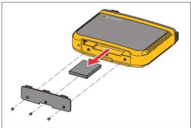
To replace the battery:
- Unscrew the three screws and remove the battery door. See Figure 16.
- Replace the battery.
- Replace and fasten the battery door.
Caution
To prevent damage to the Product, use only Fluke battery pack.
natural_image
Diagram of a yellow electronic device with a red arrow pointing to a gray component, connected by dashed lines (no text or symbols)Figure 16. Battery Replacement
Calibration
As an additional service Fluke offers the regular examination and calibration of your Logger. The recommended calibration cycle is 2 years. For more information see How to Contact Fluke on page 2.
Service and Parts
Table 6 is a list of replacement parts. To order parts and accessories, see How to Contact Fluke on page 2.
Table 6. Replacement Parts
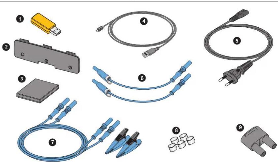
| Ref. Description Qty. Fluke Part or Model Number | |||
| 1 | WiFi-to-USB Adapter 2 4723989 | ||
| 2 | Battery Door 1 4814066 | ||
| 3 | Battery Pack, Li ion 3.7 V 2500 mAh 1 4146702 | ||
| 4 | USB Cable 1 1671807 | ||
| 5 | Line Cord, country specific (N. America, Europe, UK, Australia, Japan, India/S. Africa, Brazil) | 1 see Table 1 | |
| 6 | Test Leads 0.18 m Blue, 1000 V CAT III 1 set 5016873 | ||
| 7 | Test Leads 2 m + 2x Alligator Clips, Blue 1 set 5020006 | ||
| 8 | Cable Marker Set 1 set 5046009 | ||
| 9 | Mains Adapter MA-C8 1 4945842 | ||
Glossary
Unbalance (u2) Supply Voltage Unbalance
Condition in a three phase system in which the RMS values of the line-to-line voltages (fundamental component), or the phase angles between consecutive line voltages, are not all equal. The unbalance value is the ratio of the negative sequence to the positive sequence in percent and is typically in the range between 0 % and 2 %.
h01 [V, A] Fundamental Frequency Component
RMS value of the fundamental frequency component of voltage or current. Sub grouping according to IEC 61000-4-7 is applied.
h02 ... h50 [%] Harmonic component of voltage or current.
The ratio of the RMS value of the voltage or current harmonic components h02 ... h50 to the RMS value of the fundamental component h01 of voltage or current. Depending on the selected harmonics calculation method, Sub grouping, grouping or harmonic component is applied according to IEC 61000-4-7.
THD [%] Total Harmonic Distortion
The ratio of the RMS value of the sum of all the voltage or current harmonic components h02 ... h50 to the RMS value of the fundamental component h01 of voltage or current.
THC [V, A] Total Harmonic Content
The RMS value of the sum of all the voltage or current harmonic components h02 ... h50.
ih01 ... ih50 [%] Interharmonic component of voltage or current. The ratio of the RMS value of the voltage or current interharmonic components ih01... ih50 to the RMS value of the fundamental component h01 of voltage or current. Depending on the selected harmonics calculation method, Sub grouping or harmonic component is applied according to IEC 61000-4-7.
TID [%] Total Interharmonic Distortion
The ratio of the RMS value of the sum of all voltage or current interharmonic components ih01 ... ih50 to the RMS value of the fundamental component h01 of voltage or current. Depending on the selected harmonics calculation method, Sub grouping or harmonic component is applied according to IEC 61000-4-7.
TIC [V, A] Total Interharmonic Content
The RMS value of the sum of all the voltage or current interharmonic components ih02 ... ih50.
TDD ^[1] [%] Total Demand Distortion
The ratio of the RMS value of the sum of all the current harmonic components h02 ... h50 to I_L , the maximum demand current.
I_L^[1] [A] Maximum Demand Load Current
The current value is established at the point of common coupling and should be taken as the sum of the currents corresponding to the maximum demand during each of the twelve previous months divided by 12.
This value is required to calculate TDD and to determine the applicable current harmonic limits defined by IEEE 519. This value is a user input in the measurement configuration.
I_sc^[1] [A] Maximum Short Circuit Current at Point of Common Coupling
This value is required to determine the applicable current harmonic limits defined by IEEE 519. This value is a user input in the measurement configuration.
P_ST, P_LT PST is the short term flicker value calculated over defined 10-minute periods. PLT is the long term flicker calculated over defined 2-hour periods.
SSID Service Set Identifier (WiFi) - name of the access point or the name of a hidden SSID
[1] Requires IEEE 519/Report License.
Supported Parameters
| 1742, 1746, 1748 | ||||||||||||
| Interval | Single Phase Single Phase IT | Split Phase (2P-3W) | 3-Φ Wye (3P-4W) | 3-Φ Wye balanced | 3-Φ Delta 3-Φ Wye IT (3P-3W) | 2 Element Delta (Aron/Blondei) | 3-Φ Delta Open Leg(3P-3W) | 3-Φ High Leg Delta | Balanced 3-Φ Delta | |||
| V_AN^[1] | V | Trend: 1s-30sDemand: 5min-30minPQ: 10min | ● ● | ● ● | ●[2] | [2] | [2] | [2] | ● | |||
| V_BN^[1] | V | Trend: 1s-30sDemand: 5min-30minPQ: 10min | ● | ● ○ | ●[2] | [2] | [2] | [2] | ○ | [2] | ||
| V_CN^[1] | V | Trend: 1s-30sDemand: 5min-30minPQ: 10min | ● ○ | ●[2] | [2] | [2] | [2] | ○ | [2] | |||
| V_AB^[1] | V | Trend: 1s-30sDemand: 5min-30minPQ: 10min | ●[2] | [2] ○ | [2] | ● | ● | ● | ● | ● | ||
| V_BC^[1] | V | Trend: 1s-30sDemand: 5min-30minPQ: 10min | ●[2] ○ | [2] | ● | ● | ● | ● | ○ | |||
| VCA^[1] | V | Trend: 1s-30sDemand: 5min-30minPQ: 10min | ●[2] ○ | [2] | ● | ● | ● | ● | ○ | |||
| I_A | A | Trend: 1s-30sDemand: 5min-30min | ● | ● | ● | ● | ● | ● | ● | ● | ● | |
| I_B | A | Trend: 1s-30sDemand: 5min-30min | ● | ● ○ ● | Δ | ● ● | ○ | |||||
| I_C | A | Trend: 1s-30sDemand: 5min-30min | ● | ○ | ● | ● | ● | ● | ○ | |||
| I_N | A | Trend: 1s-30sDemand: 5min-30min | ● | ● | X | |||||||
| f | Hz | Trend: 1s-30sPQ: 10s, 10min | ● | ● | ● | ● | ● | ● | ● | ● | ● | |
| Aux 1, 2 | mV, user defined | Trend: 1s-30s | ● | ● | ● | ● | ● | ● | ● | ● | ● | |
| THD V_AN^[3] | % | Trend: 1s-30s PQ: 10min, 150/180 cycles [4] | ● ● | ● ● | ||||||||
| THD V_BN^[3] | % | Trend: 1s-30s PQ: 10min, 150/180 cycles [4] | ● ● | |||||||||
| THD V_CN^[3] | % | Trend: 1s-30s PQ: 10min, 150/180 cycles [4] | ● | |||||||||
| THD V_AB^[3] | V, | Trend: %-30s PQ: 10min, 150/180 cycles [4] | ● | ● | ● | ● | ● | |||||
| THD V_BC^[3] | V, | Trend: %-30s PQ: 10min, 150/180 cycles [4] | ● ● | ● ● | ||||||||
| THD VCA^[3] | V, | Trend: %-30s PQ: 10min, 150/180 cycles [4] | ● ● | ● ● | ||||||||
| Harmonics h01-50 V_AN^[3][5] V, % | 10min, 150/180 cycles [4] | ● ● | ● ● | |||||||||
| Harmonics h01-50 V_BN^[3][4] V, % | 10min, 150/180 cycles [4] | ● ● | ||||||||||
| Harmonics h01-50 V_CN^[3][5] | V, % | 10min, 150/180 cycles [4] | ● | |||||||||
| Harmonics h01-50 V_AB^[3][5] | V, % | 10min, 150/180 cycles [4] | ● | ● | ● | ● | ● | |||||
| Harmonics h01-50 V_BC^[3][5] | V, % | 10min, 150/180 cycles [4] | ● ● | ● ● | ||||||||
| Harmonics h01-50 V_CA^[3][5] | V, % | 10min, 150/180 cycles [4] | ● ● | ● ● | ||||||||
| Harmonics h01-50 I_A | A, % | ● | ● | ● | ● | ● | ● | ● | ● | ● | ||
| Harmonics h01-50 I_B | A, % | ● | ● | ● | ● | ● | ● | |||||
| Harmonics h01-50 I_C | A, % | ● | ● | ● | ● | ● | ||||||
| THD I_A | A, % | Trend: 1s-30s PQ: 10min, 150/180 cycles [4] | ● | ● | ● | ● | ● | ● | ● | ● | ● | |
| THD I_B | A, % | Trend: 1s-30s PQ: 10min, 150/180 cycles [4] | ● | ● | ● | ● | ● | ● | ||||
| 1742, 1746, 1748 | |||||||||||
| Interval | Single Phase Single Phase IT | Split Phase (2P-3W) | 3-Φ Wye (3P-4W) | 3-Φ Wye balanced | 3-Φ Delta 3-Φ Wye IT (3P-3W) | 2 Element Delta (Aron/Blondei) | 3-Φ Delta Open Leg(3P-3W) | 3-Φ High Leg Delta | Balanced 3-Φ Delta | ||
| THD I_C | A, % | Trend: 1s-30s PQ: 10min, 150/180 cycles [4] | ● | ● | ● | ● | ● | ||||
| THC I_N | A | Trend: 1s-30s PQ: 10min, 150/180 cycles [4] | ● | ● | X | ||||||
| TDD IA^[4] % PQ: 10min, 150/180 cycles | [4] | ● | ● | ● | ● | ● | ● | ● | ● | ● | |
| TDD IB^[4] % PQ: 10min, 150/180 cycles | [4] | ● | ● | ● | ● | ● | ● | ||||
| TDD IC^[4] | % | PQ: 10min, 150/180 cycles [4] | ● | ● | ● | ● | ● | ||||
| Flicker P_st | 1 | PQ: 10min | ● | ● | ● | ● | ● | ● | ● | ● | ● |
| Flicker P_it | 1 | PQ: 2hrs | ● | ● | ● | ● | ● | ● | ● | ● | ● |
| Events: Dip/Swell/Interruption | % Unom | 1⁄2 cycle RMS | ● | ● | ● | ● | ● | ● | ● | ● | ● |
| 1746, 1748 | |||||||||||
| Voltage unbalance | % | Trend: 1s-30s PQ: 10min | ● | ● | ● | ● | ● | ||||
| Current unbalance | % | Trend: 1s-30s PQ: 10min | ● | ● | ● | ● | ● | ||||
| TID V_AN^[3] | % | PQ: 10min | ● | ● | ● | ● | |||||
| TID V_BN^[3] | % | PQ: 10min | ● ● | ||||||||
| TID V_CN^[3] | % | PQ: 10min | ● | ||||||||
| TID V_AB^[3] | V, % | PQ: 10min | ● | ● | ● | ● | ● | ||||
| TID V_BC^[3] | V, % | PQ: 10min | ● ● | ● ● | |||||||
| TID V_CA^[3] | V, % | PQ: 10min | ● ● | ● ● | |||||||
| 1746, 1748 | |||||||||||
| Interval | Single Phase Single Phase IT | Split Phase (2P-3W) | 3-Φ Wye (3P-4W) | 3-Φ Wye balanced | 3-Φ Delta 3-Φ Wye IT (3P-3W) | 2 Element Delta (Aron/Blondei) | 3-Φ Delta Open Leg(3P-3W) | 3-Φ High Leg Delta | Balanced 3-Φ Delta | ||
| TID IA | A, % PQ: 10min | ● | ● | ● | ● | ● | ● | ● | ● | ● | |
| TID IB | A, % PQ: 10min | ● | ● | ● | ● | ● | ● | ||||
| TID IC | A, % PQ: 10min | ● | ● | ● | ● | ● | |||||
| TIC IN | A | PQ: | 10min | ● | X | ||||||
| Interhammonics ih01-50 VAN [3] | V, % | PQ: 10min | ● ● | ● ● | |||||||
| Interhammonics ih01-50 VBN [3] | V, % | PQ: 10min | ● ● | ||||||||
| Interhammonics ih01-50 VCN [3] | V, % | PQ: 10min | ● | ||||||||
| Interhammonics ih01-50 VAB [3] | V, % | PQ: 10min | ● | ● | ● | ● | ● | ||||
| Interhammonics ih01-50 VBC [3] | V, % | PQ: 10min | ● ● | ● ● | |||||||
| Interhammonics ih01-50 VCA [3] | V, % | PQ: 10min | ● ● | ● ● | |||||||
| Events: Dip/Swell/ Interruption | % Unom % sliding reference | 1⁄2 cycle RMS | ● | ● | ● | ● | ● | ● | ● | ● | ● |
| Events: Rapid voltage change | % Unom 1⁄2 cycle RMS | ● | ● | ● | ● | ● | ● | ● | ● | ● | |
| Events: Inrush current | A | 1⁄2 cycle RMS | ● | ● | ● | ● | ● | ● | ● | ● | ● |
| Events: Main Signaling % Unom 200ms RMS | ● | ● | ● | ● | ● | ● | ● | ● | ● | ||
| 1748 | |||||||||||
| Interval | Single Phase Single Phase IT | Split Phase (2P-3W) | 3-Φ Wye (3P-4W) | 3-Φ Wye balanced | 3-Φ Delta 3-Φ Wye IT (3P-3W) | 2 Element Delta (Aron/Blondei) | 3-Φ Delta Open Leg(3P-3W) | 3-Φ High Leg Delta | Balanced 3-Φ Delta | ||
| Events: Waveform deviation % | Unom 10.24kHz | ● | ● | ● | ● | ● | ● | ● | ● | ● | |
| Event Recording: RMS profile | V, A 1⁄2 cycles RMS up to 10s | ● | ● | ● | ● | ● | ● | ● | ● | ● | |
| Event Recording: Waveform V | A 10.24kHz up to 10 cycles | ● | ● | ● | ● | ● | ● | ● | ● | ● | |
| Event Recording: MS RMS profile | V,A 10/12 cycles up to 120s | ● | ● | ● | ● | ● | ● | ● | ● | ● | |
| ● = Measured valuesX = Optional for harmonics analysisΔ = Calculated values○ = Simulated values (derived from phase 1)[1] Simulated in load studies if U_nom is specified[2] Available in Advanced graphs[3] Not available in load studies[4] Requires IEEE 519/Report License[5] Fluke 1742: only with IEEE 519/Report License | |||||||||||
Power
| 1742, 1746, 1748 | ||||||||||||
| Interval | Single Phase Single Phase IT | Split Phase (2P-3W) | 3-Φ Wye (3P-4W) | 3-Φ Wye Balanced | 3-Φ Delta 3-Φ Wye IT (3P-3W) | 2 Element Delta (Aron/Blondel) | 3-Φ Delta Open Leg (3P-3W) | 3-Φ High Leg Delta | Balanced 3-Φ Delta | |||
| PA, PA fund [3] | W | Trend: 1s-30s | ● ● | ● ● | ||||||||
| PB, PB fund[3] | W | Trend: 1s-30s | ● | ● ○ | ||||||||
| PC, PC fund[3] | W | Trend: 1s-30s | ● ○ | |||||||||
| PTotal, PTotal fund[3] | W | Trend: 1s-30s | ● | ● | ○ | ● | ● | ● | ● | ● | ● | |
| QA, QA fund[3] | var | Trend: 1s-30s | ● ● | ● ● | ||||||||
| QB, QB fund[3] | var | Trend: 1s-30s | ● | ● ○ | ||||||||
| QC, QC fund[3] | var | Trend: 1s-30s | ● ○ | |||||||||
| QTotal, QTotal fund[3] | var | Trend: 1s-30s | ● | ○ | ● | ● | ● | ● | ● | ● | ||
| S_A^[1] | VA | Trend: 1s-30s | ● ● | ● ● | ||||||||
| S_B^[1] | VA | Trend: 1s-30s | ● | ● ○ | ||||||||
| S_C^[1] | VA | Trend: 1s-30s | ● ○ | |||||||||
| S_TOTAL^[1] | VA | Trend: 1s-30s | ● | ● | ○ | ● | ● | ● | ● | ● | ● | |
| PF_A^[3] | 1 | Trend: 1s-30s | ● | ● | ● | ● | ||||||
| PF_B^[3] | 1 | Trend: 1s-30s | ● | ● | ○ | |||||||
| PF_C^[3] | 1 | Trend: 1s-30s | ● | ○ | ||||||||
| PF_Total^[3] | 1 | Trend: 1s-30s | ● | ● | ○ | ● | ● | ● | ● | ● | ● | |
| ● = Measured values○ = Simulated values (derived from phase 1)[1] Simulated in load studies if U_nom is specified[2] Secondary displayed values[3] Not available in load studies | ||||||||||||
General Specifications
Warranty
Logger 2 years (battery not included)
Accessories....1 year
Calibration Cycle....2 years
Dimensions....23.0 cm x 18.0 cm x 5.4 cm (9.1 in x 7.1 in x 2.1 in)
Weight 1 kg (2.2 lb)
Environmental Specifications
Logger
Temperature
Operating ....-25 °C to +50 °C (-13 °F to +122 °F) warm up the Product to -10 °C (14 °F) before you turn on power
Storage without battery ....-25 °C to +60 °C (-13 °F to +140 °F)
Storage with battery ....-20 °C to +50 °C (-4 °F to +122 °F)
Operating Humidity .....IEC60721-3-3: 3K6:
-25 °C to +30 °C (-13 °F to +86 °F): ≤100 %
40 °C (104 °F): 55 %
50 °C (122 °F): 35 %
Altitude
Operating 2000 m (up to 4000 m derate to 1000 V CAT II/600 V CAT III/300 V CAT IV)
Storage....12 000 m
Battery....Li-ion 3.7 V, 8.5 Wh, customer-replaceable
Temperature
Storage....-20 °C to +50 °C (-4 °F to +122 °F)
Charge 0 °C to 45 °C (32 °F to 113 °F)
IP Rating.....IEC 60529: IP50 / IEC 60529: IP65 with IP65 rated voltage connector
Vibration......IEC 60721-3-3 / 3M2
1742/1746/1748
Users Manual
Safety
General IEC 61010-1: Pollution Degree 2
Mains Input (IEC C8)....Overvoltage Category II
Mains Input (4 mm test lead)....Overvoltage Category IV
Measurement ....IEC 61010-2-033: CAT IV 600 V / CAT III 1000 V
Power Supply ......Overvoltage Category IV, Pollution Degree 2
Mains Adapter MA-C8 CAT II 300 V
Electromagnetic Compatibility (EMC)
International ....IEC 61326-1: Industrial
CISPR 11: Group 1, Class A
Group 1: Equipment has intentionally generated and/or uses conductively-coupled radio frequency energy that is necessary for the internal function of the equipment itself.
Class A: Equipment is suitable for use in all establishments other than domestic and those directly connected to a low-voltage power supply network that supplies buildings used for domestic purposes. There may be potential difficulties in ensuring electromagnetic compatibility in other environments due to conducted and radiated disturbances.
Emissions that exceed the levels required by CISPR 11 can occur when the equipment is connected to a test object.
Korea (KCC)....Class A Equipment (Industrial Broadcasting & Communication Equipment)
Class A: Equipment meets requirements for industrial electromagnetic wave equipment and the seller or user should take notice of it. This equipment is intended for use in business environments and not to be used in homes.
USA (FCC) 47 CFR 15 subpart C.
Wireless Radio with Adapter with USB/WiFi or USB/WiFi + BLE Adapter (optional accessory)
Frequency Range....2412 MHz to 2462 MHz
Output Power ....<100 mW
Electrical Specifications
Power Supply
Voltage Range
using safety plug input with power
from the measurement circuit....100 V to 500 V
using MA-C8 with standard
power cord (IEC 60320 C7)....100 V to 240 V
Power consumption......Maximum 50 VA (maximum 15 VA when powered using MA-C8 adapter)
Maximum no-load consumption ....<0.3 W only when powered using IEC 60320 input
Efficiency....≥68.2% (in accordance with energy efficiency regulations)
Mains Frequency....50/60 Hz ±15 %
Battery Power.....Li-ion 3.7 V, 9.25 Wh, customer-replaceable
On-Battery Runtime .....Typically 4 hr
Charging Time....<6 hr
Voltage Inputs
Number of Inputs....4 (3 phases referenced to neutral)
Maximum Input Voltage 1000 V _rms , CF 1.7
Input Impedance 10 MΩ
Bandwidth 42.5 Hz to 3.5 kHz
Scaling 1:1 and variable
Current Inputs
Number of Inputs....4 (3 phases and neutral), mode selected automatically for attached sensor
Input Voltage
Clamp....500 mV rms / 50 mV rms ; CF 2.8
Rogowski Coil 150 mV rms / 15 mV rms at 50 Hz, 180 mV rms / 18 mV rms at 60 Hz; CF 4; all at nominal probe range
Range....1 A to 150 A / 10 A to 1500 A with thin flexible current probe i17XX-flex1500 IP 24 in
3 A to 300 A / 30 A to 3000 A with thin flexible current probe i17XX-flex3000 IP 24 in
6 A to 600 A / 60 A to 6000 A with thin flexible current probe i17XX-flex6000 IP 36 in
40 mA to 4 A / 0.4 A to 40 A with 40 A clamp i40s-EL
Bandwidth 42.5 Hz to 3.5 kHz
Scaling 1:1 and variable
1742/1746/1748
Users Manual
Auxiliary Inputs
Number of Inputs....2 (Analog with auxiliary adapter, or up to 2 BLE devices simultaneously)
Input Range....0 V dc to ±10 V dc or 0 V dc to ±1000 V dc (with optional adapter, 1 reading/s)
Displayed Units ....User configurable (7 characters, for example °C, psi, or m/s)
Wireless Bluetooth connection (check for availability)
Number of Inputs....2
Supported Modules ......Fluke Connect® 3000 series
Acquisition....1 reading/s
Data Acquisition
Resolution 16-bit synchronous sampling
Sampling Frequency 10.24 kHz at 50/60 Hz, synchronized to mains frequency
Input Signal Frequency ....50/60 Hz (42.5 Hz to 69 Hz)
Circuit Types ....1-Φ, 1-Φ IT, Split phase, 3-Φ wye, 3-Φ wye IT, 3-Φ wye balanced, 3-Φ delta, 3-Φ Aron/Blondel (2-element delta), 3-Φ delta open leg, 3-Φ high leg delta, 3-Φ delta balanced. Currents only (load studies)
Data Storage .......Internal flash memory (not user replaceable)
Memory Size ....Typical 20 logging sessions of 4 weeks with 1-minute intervals and 500 events
Trend Interval
Measured Parameter ......Voltage, Current, Aux, Frequency, THD V, THD A, Power, Power Factor, fundamental Power, DPF, energy
Averaging Interval ....User selectable: 5 min, 10 min, 15 min, 20 min, 30 min, off
Averaging time min/max values ...... Voltage, Current: Full cycle RMS updated every half cycle (URMS1/2 according to IEC 61000-4-30) AUX, Power: 20 ms
Demand Interval
Measured Parameter ......Energy (Wh, varh, VAh), PF, maximum demand, cost of energy
USB-A File transfer via USB Drive, Firmware updates, max. supply current: 120 mA
WiFi (x2)
Supported modes....Direct connection and connection to infrastructure
Security ......WPA2-AES with pre-shared key
Accuracy at Reference Conditions
| Parameter Range Maximum Resolution | Intrinsic Accuracy at Reference Conditions (% of Reading + % of Range) | ||||
| Voltage 1000 V 0.1 V ±0.1 % of nominal voltage | [1][2] | ||||
| Current | Direct Input | Rogowski Mode | 15 mV 0.01 mV ±(0.3 % + 0.02 %) | ||
| 150 mV 0.1 mV ±(0.3 % + 0.02 %) | |||||
| Clamp Mode | 50 mV 0.01 mV ±(0.2 % + 0.02 %) | ||||
| 500 mV 0.1 mV ±(0.2 % + 0.02 %) | |||||
| 1500 A Flexi | 150 A 0.01 A ±(1 % + 0.02 %) | ||||
| 1500 A 0.1 A ±(1 % + 0.02 %) | |||||
| 3000 A Flexi | 300 A 1 A ±(1 % + 0.03 %) | ||||
| 3000 A 10 A ±(1 % + 0.03 %) | |||||
| 6000 A Flexi | 600 A 1 A ±(1.5 % + 0.03 %) | ||||
| 6000 A 10 A ±(1.5 % + 0.03 %) | |||||
| 40 A | 4 A 1 mA | (0.7 % + 0.02 %) | |||
| 40 A 10 mA (0.7 % + 0.02 %) | |||||
| Frequency | 42.5 Hz to 69 Hz | 0.01 Hz | ±0.1 % | ||
| Voltage Min/Max | 1000 V | 0.1 V | ±2 % of nominal input voltage [1] | ||
| Current Min/Max | defined by accessory | defined by accessory | ±(5 % + 0.2 %) | ||
| THD on Voltage | 1000 % | 0.1 % | ±(2.5 % + 0.05 %) | ||
| THD on Current | 1000 % | 0.1 % | ±(2.5 % + 0.05 %) | ||
| Voltage Harmonics 2nd ... 50th | 1000 V 0.1 V | ≥1 V: ±5 % of reading | |||
| <1 V: ±0.05 V | |||||
| Current Harmonics 2nd ... 50th | defined by accessory | defined by accessory | ≥3 % of current range: ±5 % of reading | ||
| <3 % of current range: ±0.15 % of range | |||||
| Flicker PLT, PST | 0 to 20 | 0.01 | 5 % | ||
| [1] Only for calibration laboratories[2] 0 °C ... 45 °C: Intrinsic accuracy x 2, outside of 0 °C ... 45 °C: Intrinsic accuracy x 3 | |||||
Power/Energy
| Parameter Direct Input | [1] | iFlex1500-12 iFlex | 3000-24 iFlex6000-36 i | 40S-EL | |
| Power Range W, VA, var | Clamp: 50 mV/500 mVRogowski: 15 mV/150 mV | 150 A / 1500 A 300 A / | 3000 A 600 A / 6000 A | 4 A / 40 A | |
| Clamp: 50 W/500 WRogowski: 15 W/150 W | 150 kW / 1.5 MW 300 kW / 3 MW 600 kW / 6 MW 4 kW / 40 kW | ||||
| Max. Resolution W, VA, var 0.1 W 0.01 kW / 0.10 kW 1 kW / 10 kW 1 kW / 10 kW | 0.1 W / 1 W | ||||
| Max. Resolution PF, DPF 0.01 | |||||
| Phase (Voltage to Current) [1] | ±0.2° | ±0.28° | ±1° | ||
| [1] In the range of 100 V ... 500 V; also known as Udln | |||||
Intrinsic Uncertainty ±(% of measurement value + % of power range)
| Parameter | Influence Quantity | Direct Input[1] | iFlex1500-12 iFlex3000-24 iFlex6000-36 i40S-EL | |||
| Clamp: 50 mV/500 mVRogowski: 15 mV/150 mV | 150 A / 1500 A 300 A | 3000 A 600 A / 6000 A | A / 40 A | |||
| Active Power P Active Energy Ea | PF ≥0.99 | 0.5 % + 0.005 % | 1.2 % + 0.005 % | 1.2 % + 0.0075 % | 1.7 % + 0.0075 % | 1.2 % + 0.005 % |
| 0.1 ≤ PF <0.99 | see Formula 1 | see Formula 2 | see Formula 3 | see Formula 4 | see Formula 5 | |
| Apparent Power S Apparent Energy Eap | 0 ≤ PF ≤1 | 0.5 % + 0.005 % | 1.2 % + 0.005 % | 1.2 % + 0.0075 % | 1.2 % + 0.0075 % | 1.2 % + 0.005 % |
| Reactive Power Q Reactive Energy Er | 0 ≤ PF ≤1 | 2.5 % of measured apparent power/energy | ||||
| Power Factor PF Displacement Power Factor DPF/cosφ | - | Reading ±0.025 | ||||
| Additional uncertainty (% of power high-range) | VP-N >250 V | 0.015 % | 0.015 % | 0.0225 % | 0.0225 % | 0.015 % |
| [1] Only for calibration laboratoriesReference Conditions:Environmental: 23 °C ±5 °C, instrument operating for at least 30 minutes, no external electrical/magnetic field, RH <65 %Input conditions: CosΦ/PF=1, Sinusoidal signal f=50/60 Hz, power supply 120 V/230 V ±10 %.Current and power specifications: Input voltage 1ph: 120 V/230 V or 3ph wye/delta: 230 V/400 VInput current >10 % of current rangePrimary conductor of clamps or Rogowski coil in center positionTemperature Coefficient: Add 0.1 x specified accuracy for each degree C above 28 °C or below 18 °C | ||||||
1742/1746/1748
Users Manual
Formula 1: (2.50.0051PF^23PF×)+
Formula 2: ( % .20.0051PF^22PF_x )+
Formula 3: % .20.001PF2PF% +
Formula 4: ( 1PF2PF)^2 +
Formula 5: ( 1PF^2PF )
Example:
Measurement at 120 V/16 A using an iFlex1500-12 in low range. Power Factor is 0.8
Active power uncertainty _P
$$ \sigma_ {P} = \pm \left(\left(1. 2 \% + \frac {\sqrt {1 - 0 . 8 ^ {2}}}{2 0}\right) + 0. 0 0 5 \% R _ {\text {Range}}\right) = \pm (1. 5 7 5 \% + 0. 0 0 5 \% \times 1 0 0 0 \mathrm{V} \times 1 5 0 \mathrm{A}) = \pm (1. 5 7 5 \% + 7. 5 \mathrm{W}) $$
The uncertainty in W is ±(1.575 % × 120 V × 16 A × 0.8 + 7.5 W) = ±31.7 W
Apparent power uncertainty _S
$$ \sigma_ {S} = \pm (1. 2 \% 0. 0 0 5 \% S \times \text { Range }) = \pm (1. 2 \% + 0. 0 0 5 \% \times 1 0 0 0 V \times 1 5 0 A) = \pm (1. 2 \% + 7. 5 V A) $$
The uncertainty in VA is ± (1.2% × 120V× 16A + 7.5VA) = ± 30.54 VA
Reactive/non-active power uncertainty _Q
$$ \sigma_ {Q} = \pm (2.5 \% \times S) = \pm (2.5 \% \times 120 V \times 16 A) = \pm 48 \text {var} $$
In case of a measured voltage that is >250 V, the additional error is calculated with:
Adder = 0.015 % ×S High Range = 0.015 % × 1000 V × 1500 A = 225 W/VA/var
iFlex Probe Specifications
| Flexible Current Probe Specifications | i17XX-FLEX1.5KIP | i17XX-FLEX3KIP | i17XX-FLEX6KIP |
| Measuring range | 1 A ac to 150 A ac10 A ac to 1500 A ac | 3 A ac to 300 A ac30 A ac to 3000 A ac | 6 A ac to 600 A ac60 A ac to 6000 A ac |
| Weight 170 g (0.38 lb) 170 g (0.38 lb) 190 g (0.42 lb) | |||
| Probe Cable Length 610 mm (24 in) 610 mm (24 in) 915 mm (36 in) | |||
| Probe Cable Diameter 7.5 mm (0.3 in) | |||
| Minimum Bending Radius 38 mm (1.5 in) | |||
| Nondestructive current 100 kA (50/60 Hz) | |||
| Intrinsic Error at reference condition | ±0.7 % of reading [Reference Condition: Environmental: 23 °C ±5 °C, no external electrical/magnetic field, RH 65 %. Primary conductor in center position] | ||
| Accuracy Logger + iFlex | ±(1 % of reading + 0.02 % of range) | ±(1.5 % of reading + 0.03 % of range) | |
| Temperature Coefficient over operating temperature range | 0.05 % of reading / °C (0.028 % of reading / °F) | 0.1 % of reading / °C (0.056 % of reading / °F) | |
| Working Voltage | 1000 V CAT III, 600 V CAT IV | ||
| Output Cable length 2.5 m (8.2 ft) | |||
| Probe Cable Material | TPR | ||
| Coupling Material | POM + ABS/PC | ||
| Output Cable Material | TPR/PVC | ||
| Temperature, operating | -25 °C to +70 °C (-13 °F to +158 °F) temperature of conductor under test shall not exceed 80 °C (176 °F) | ||
| Temperature, non-operating | -40 °C to +80 °C (-40 °F to +176°F) | ||
| Relative humidity, operating | IEC 60721-3-3: 3K6:-25 °C to +30 °C (-13 °F to +86 °F): ≤100 %40 °C (104 °F): 55 %50 °C (122 °F): 35 % | ||
1742/1746/1748
Users Manual
| Flexible Current Probe Specifications | i17XX-FLEX1.5KIP | i17XX-FLEX3KIP | i17XX-FLEX6KIP |
| Altitude, operating | 2000 m (6500 ft) up to 4000 m (13 000 ft) derate to 1000 V CAT II/600 V CAT III/300 V CAT IV | ||
| Altitude, storage 12 km (40 000 ft) | |||
| IP Rating IEC 60529:IP65 | |||
| Warranty 1 year | |||
| External magnetic field rejection in reference to external current (with cable >100 mm from the head-coupling and r-coil) | 40 dB | ||
| Phase shift < ±0.5° | |||
| Bandwidth 10 Hz to 23.5 kHz | |||
| Frequency derating | I x f ≤385 kA Hz | ||
Positioning error with position of conductor in the probe window.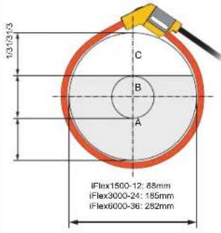 | A: ±(1 % of reading + 0.02 % of range) | ±(1.5 % of reading + 0.03 % of range) | |
| B: ±(1.5 % of reading + 0.02 % of range) | ±(2.0 % of reading + 0.03 % of range) | ||
| C: ±(2.5 % of reading + 0.02 % of range) ±(4 % of reading + 0.03 % of range) | |||
i40s-EL Current Clamp Specifications
See Table 7 for setup instructions.
Table 7. i40s-EL Setup
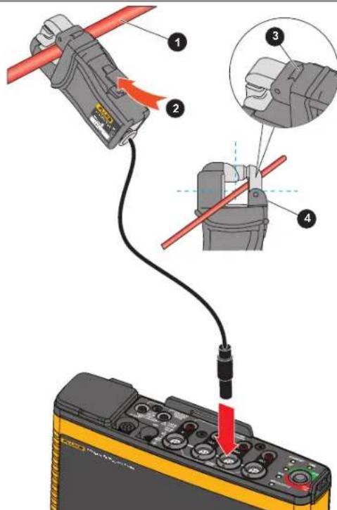 | Item Description |
| 1 Single Insulated current carrying conductor | |
| 2 Release button | |
| 3 Load direction arrow | |
| 4 Tactile barrier |
Measuring range ....40 mA to 4 Aac / 0.4 Aac to 40 Aac
Crest factor....≤3
Nondestructive current 200 A (50/60Hz)
Intrinsic Error at reference condition .... ±0.5% of reading
1742/1746/1748
Users Manual
Accuracy 174x + clamp .... ±(0.7 % of reading + 0.02 % of range)
Phase shift
<40 mA....unspecified
400 mA to 40 A ....< ±1°
Temperature Coefficient over
Operating temperature range 0.015 % of reading / °C
0.0083 % of reading / °F
Influence of adjacent conductor ....≤15 mA/A (@ 50/60 Hz)
Influence of conductor position
in jaw opening ....±0.5 % of reading (@ 50/60 Hz)
Bandwidth....10 Hz to 2.5 kHz
Working Voltage 600 V CAT III, 300 V CAT IV
[1] Reference Condition:
• Environmental: 23 °C ±5 °C, no external electrical/magnetic field, RH 65 %
• Single primary conductor in center position
Size (H x W x L) 110 mm x 50 mm x 26 mm
(4.33 in x 1.97 in x 1.02 in)
Maximum conductor size....15 mm (0.59 in)
Output cable length 2 m (6.6 ft)
Weight 190 g (6.70 oz)
Material.....Case ABS and PC
Output cable: TPR/PVC
Temperature operating....-10 °C to +55 °C
(-14 °F to 131 °F)
Temperature, non-operating....-20 °C to +70 °C
(-4 °F to 158 °F)
Relative Humidity, operating 15% to 85% non-condensing
Max Operating Altitude 2000 m (6500 ft)
up to 4000 m (13 000 ft) derate to 600 V CAT II/300 V CAT IV
Max Storage Altitude 12 km (40 000 ft)
Warranty....1 year
GPS Receiver Specifications (Fluke-174X-GPS-REC)
Supported Global Navigation Satellite System .....GPS
Receiver sensitivity ....min. -185 dBW
Time accuracy.... ±1 μs
Acquisition time....Cold start: Approx. 45 s
Reacquisition: 2 s
Power consumption....4.0 V to 5.5 V, 90 mA
Case material ......Polycarbonate thermoplastic, black
Ingress protection....Receiver: IEC 60529 IPX7, immersion in 1 meter of water for 30 minutes.
Connector mated with 174x: IEC 60529 IP65
Cable length 5 m
Dimensions 6.1 cm x 2 cm (∅ 2.4 in x 0.77 in)
Weight 170g (5.9 oz)
Mounting options....Magnet, central threaded recess M3 x 4mm
Operating temperature (Receiver only)....-30 °C to +80 °C (-22 °F to +176 °F)
Storage temperature ....-25 °C to +85 °C (-13 °F to +185 °F)
1742/1746/1748
Users Manual
- LIMITED WARRANTY AND LIMITATION OF LIABILITY
- Documentation and Software Notice
- Open Source Obligations
- Open Source Request
- Everett, WA 98203
- Table of Contents
- Title Page
- 1742/1746/1748
- Users Manual
- Introduction
- Note
- How to Contact Fluke
- Safety Information
- Before You Start
- WiFi and WiFi/BLE-to-USB Adapter
- Magnet Hanger Kit
- Voltage Test Leads
- iFlexi Current Probe
- Storage
- Accessories
- User Interface
- Power Supply
- Mains Power Source
- Measurement Line Power Source
- Battery Power Source
- Caution
- To prevent damage to the Product:
- Start/Stop Button and Status LEDs
- Energy Analyze Plus Software
- System Requirements
- How to Connect to Energy Analyze Plus
- USB Cable
- Ethernet
- WiFi Direct Connect
- WiFi to Infrastructure
- First-time Use/Setup Wizard
- Before you start:
- First Measurements
- To set up the Logger:
- To set up the software:
- Instrument and Logging Setup
- Measurement Configuration
- Connection Verification
- Logging Setup
- Instrument Setup
- Study Type
- Topology (Distribution System)
- Single Phase
- Single Phase IT
- Split Phase
- 3-Φ Wye
- 3-Φ Wye IT
- 3-Φ Wye Balanced
- 3-Φ Delta
- Element Delta (Aron/Blondel)
- 3-Φ Delta Open Leg
- 3-Φ High Leg Delta
- 3-Φ Delta Balanced
- Nominal Voltage
- Nominal Frequency
- Voltage Ratio (only in energy studies)
- Current Range
- Current Ratio
- Harmonics Calculation Method
- Examples:
- Grouped Harmonics.
- Flicker
- Configuration of Events
- Voltage Dips
- Parameters to configure:
- Voltage Swells
- Voltage Interruptions
- Rapid Voltage Changes
- Waveform Deviation
- Inrush Current
- Logging Session Setup
- Connection Verification and Correction
- Instrument Name
- Time Synchronization
- Ethernet Configuration
- Update Firmware
- To update:
- License Activation
- Retrieve Service Data from the Logger
- Reset to Factory Defaults
- Auto-Copy Data to USB
- GPS Time Synchronization
- Licensed Features
- WiFi Infrastructure
- 1742-6/Upgrade
- 1742-8/Upgrade
- 1746-8/Upgrade
- IEEE 519/Report
- Maintenance
- How to Clean
- Battery Replacement
- Warning
- Calibration
- Service and Parts
- Glossary
- General Specifications
- Warranty
- Environmental Specifications
- Logger
- Safety
- Electromagnetic Compatibility (EMC)
- Wireless Radio with Adapter with USB/WiFi or USB/WiFi + BLE Adapter (optional accessory)
- Electrical Specifications
- Voltage Inputs
- Current Inputs
- Auxiliary Inputs
- Wireless Bluetooth connection (check for availability)
- Data Acquisition
- Trend Interval
- Demand Interval
- i40s-EL Current Clamp Specifications
- GPS Receiver Specifications (Fluke-174X-GPS-REC)
Brand : FLUKE
Model : 1742
Category : Energy meter