
GS716Tv2 - Uncategorized NETGEAR - Free user manual and instructions
Find the device manual for free GS716Tv2 NETGEAR in PDF.


| Product Type | 16-Port Gigabit Smart Switch |
| Ports | 16 Gigabit Ethernet ports (RJ-45) |
| Management Interface | Web-based GUI, SNMP (v1/v2/v3), Smart Control Center utility |
| Default IP Address | 192.168.0.239 |
| Default Password | password |
| Dimensions (approximate) | 330 x 230 x 44 mm (desktop form factor) |
| Weight (approximate) | 2.5 kg |
| Power Supply | External power adapter (input 100-240V AC, output 12V DC) |
| Power Consumption | Max 25 W |
| Main Functions | VLAN (802.1Q), QoS (CoS, DiffServ), Link Aggregation (LACP), Spanning Tree (STP/RSTP/MSTP), IGMP Snooping, Port Security, ACL, DHCP Filtering, Green Ethernet, LLDP |
| Maintenance | Firmware upgrade via TFTP/HTTP, configuration upload/download, dual image support |
| Safety and Compliance | FCC Class B, CE, ICES-003, RoHS compliant |
| Spare Parts and Repairability | No user-serviceable parts; contact NETGEAR support for assistance |
| General Information | NETGEAR GS716Tv2, 16-port Gigabit Smart Switch, software administration manual available (303 pages) |
Frequently Asked Questions - GS716Tv2 NETGEAR
User questions about GS716Tv2 NETGEAR
0 question about this device. Answer the ones you know or ask your own.
Ask a new question about this device
Download the instructions for your Uncategorized in PDF format for free! Find your manual GS716Tv2 - NETGEAR and take your electronic device back in hand. On this page are published all the documents necessary for the use of your device. GS716Tv2 by NETGEAR.
USER MANUAL GS716Tv2 NETGEAR
Gigabit Smart Switches
Software Administration Manual
350 East Plumeria Drive San Jose, CA 95134 USA
October 2012 202-10484-05 v2.0
©2012 All rights reserved
No part of this publication may be reproduced, transmitted, transcribed, stored in a retrieval system, or translated into any language in any form or by any means without the written permission of NETGEAR, Inc.
NETGEAR, the NETGEAR logo, and Connect with Innovation are trademarks and/or registered trademarks of NETGEAR, Inc. and/or its subsidiaries in the United States and/or other countries. Information is subject to change without notice. Other brand and product names are registered trademarks or trademarks of their respective holders. ©2012 All rights reserved.
Technical Support
Thank you for choosing NETGEAR. To register your product, get the latest product updates, get support online, or for more information about the topics covered in this manual, visit the Support website at
http://support.netgear.com
Phone (US & Canada only): 1-888-NETGEAR
Phone (Other Countries): Check the list of phone numbers at
http://support.netgear.com/app/answers/detail/a_id/984
Statement of Conditions
To improve internal design, operational function, and/or reliability, NETGEAR reserves the right to make changes to the products described in this document without notice. NETGEAR does not assume any liability that may occur due to the use, or application of, the product(s) or circuit layout(s) described herein.
Revision History
| Publication Part Number Version | Publish Date Comments | |
| 202-10484-05 v2.0 October 2012 | Hardware/Software | Updates |
| 202-10484-03 v1.0 November 2010 | First publication |
Contents
Chapter 1 Switch Information and Setup
GS716T and GS724T Smart Switch Setup 10
Switch Management Interface 10
Connecting the Switch to the Network ..... 11
Switch Discovery in a Network with a DHCP Server 12
Switch Discovery in a Network without a DHCP Server ..... 14
Network Settings Configuration on the Administrative System .....15
Web Access 16
Smart Control Center Utilities 17
Network Utilities 17
Configuration Upload and Download 19
Firmware Upgrade 20
Viewing and Managing Tasks. 22
User Interfaces 23
Web Interface 23
SNMP Management 28
Interface Naming Convention 29
Chapter 2 System Information Features
Management....31
System Information....32
IP Configuration 33
IPv6 Network Configuration 35
IPv6 Network Neighbor. 37
Time 38
Denial of Service 44
DNS 47
Green Ethernet 49
License 56
Show License 56
License Features 57
SNMP 58
SNMPV1/V2....58
Trap Flags 61
SNMP v3 User Configuration .....62
LLDP....63
LLDP Configuration 63
LLDP Port Settings 65
LLDP-MED Network Policy. 66
GS716T and GS724T Gigabit Smart Switches
LLDP-MED Port Settings 67
Local Information 68
Neighbors Information 72
Services — DHCP Filtering 76
DHCP Filtering Configuration 76
Interface Configuration 77
Chapter 3 Switching Features
Ports 79
Port Configuration....80
Flow Control 82
Link Aggregation Groups 83
LAG Configuration 84
LAG Membership 85
LACP Configuration 87
LACP Port Configuration 88
VLANs 89
VLAN Configuration 89
VLAN Membership Configuration 90
Port VLAN ID Configuration 92
Voice VLAN 94
Voice VLAN Properties. 94
Voice VLAN Port Setting 95
Voice VLAN OUI....96
Auto-VoIP Configuration....98
Spanning Tree Protocol 99
STP Switch Configuration....100
CST Configuration 102
CST Port Configuration 103
CST Port Status 105
Rapid STP 106
MST Configuration 107
MST Port Configuration 109
STP Statistics 111
Multicast 112
Auto-Video Configuration 112
IGMP Snooping 113
IGMP Snooping Querier 124
Address Table 128
MAC Address Table 128
Dynamic Address Configuration 130
Static MAC Address 131
Multiple Registration Protocol Configuration 132
MRP Configuration 133
MRP Port Settings 134
MMRP Statistics 135
MSRP Statistics 137
GS716T and GS724T Gigabit Smart Switches
MSRP Reservation Parameters .....139
Qav Parameters 141
MSRP Streams Information 143
802.1AS 145
802.1AS Configuration 145
802.1AS Port Settings 147
802.1AS Statistics....149
Chapter 4 Quality of Service Features
Class of Service 151
Basic CoS Configuration....152
CoS Interface Configuration 153
Interface Queue Configuration 155
802.1p to Queue Mapping 156
DSCP to Queue Mapping 158
Differentiated Services 159
Defining DiffServ....159
DiffServ Configuration....160
Class Configuration 161
IPv6 Class Configuration 164
Policy Configuration 167
Service Configuration....170
Service Statistics ......171
Chapter 5 Device Security
Management Security Settings....173
Change Password 174
RADIUS Configuration 175
Configuring TACACS+....181
Authentication List Configuration .....184
Configuring Management Access. 185
HTTP Configuration 186
Secure HTTP Configuration 187
Certificate Download....188
Access Profile Configuration....190
Access Rule Configuration....192
Port Authentication 193
802.1X Configuration 194
Port Authentication....195
Port Summary....198
Traffic Control 200
MAC Filter Configuration 200
MAC Filter Summary 202
Storm Control 203
Port Security Configuration. 204
Port Security Interface Configuration .....205
Security MAC Address 207
GS716T and GS724T Gigabit Smart Switches
Protected Ports Membership 208
Configuring Access Control Lists 209
ACL Wizard 210
MAC ACL 211
MAC Rules 212
MAC Binding Configuration 214
MAC Binding Table....215
IP ACL 216
IP Rules 217
IP Extended Rules 219
IPv6 ACL 222
IPv6 Rules 223
IP Binding Configuration....226
IP Binding Table 227
Chapter 6 Monitoring the System
Ports 229
Switch Statistics 229
Port Statistics 232
Port Detailed Statistics 233
EAP Statistics 240
System Logs. 241
Memory Logs 242
FLASH Log Configuration. 244
Server Log Configuration 246
Trap Logs 248
Event Logs 249
Port Mirroring 250
Multiple Port Mirroring 250
Chapter 7 Maintenance
Reset 253
Device Reboot 253
Factory Default 254
Upload File From Switch 255
TFTP File Upload 255
HTTP File Upload 256
Download File To Switch 257
TFTP File Download. 257
HTTP File Download 260
File Management 261
Dual Image Configuration....261
Dual Image Status 263
Troubleshooting 264
Ping 264
Ping IPv6 266
Traceroute 267
Chapter 8 Help
Online Help....269
Support 269
User Guide....270
Registration 271
Appendix A Hardware Specifications and Default Values
GS716T and GS724T Gigabit Smart Switches Specifications .....273
GS716T Specifications 273
GS724T Specifications 273
GS716T and GS724T Switch Performance .....274
GS716T and GS724T Switch Features and Defaults. 274
Port Characteristics ......274
Traffic Control....275
Quality Of Service....275
Security. 275
System Setup 276
Management....276
Other Features ......277
Appendix B Configuration Examples
Virtual Local Area Networks (VLANs)....279
VLAN Example Configuration .....281
Access Control Lists (ACLs). 282
MAC ACL Example Configuration .....282
Standard IP ACL Example Configuration .....284
Differentiated Services (DiffServ)....285
Class. 286
DiffServ Traffic Classes .....286
Creating Policies. 287
DiffServ Example Configuration .....288
802.1X 290
802.1X Example Configuration .....291
MSTP 293
MSTP Example Configuration .....295
Appendix C Notification of Compliance
Index
GS716T and GS724T Gigabit Smart Switches
The NETGEAR ^® GS716T and GS724T Smart Switch Software Administration Manual describes how to configure and operate the GS716T and GS724T Gigabit Smart Switches by using the Web-based graphical user interface (GUI). This manual describes the software configuration procedures and explains the options available within those procedures.
Document Organization
The GS716Tv2 and GS724Tv3 Software Administration Manual contains the following chapters:
• Chapter 1, Switch Information and Setup, contains information about performing the initial system configuration and accessing the user interface.
• Chapter 2, System Information Features, describes how to configure administrative features such as SNMP, DHCP, and port information.
- Chapter 3, Switching Features, describes how to manage and monitor the layer 2 switching features.
• Chapter 4, Quality of Service Features, describes how to manage the Access Control Lists (ACLs), and how to configure Differentiated Services and Class of Service features.
- Chapter 5, Device Security, contains information about configuring switch security information such as port access control and RADIUS server settings.
• Chapter 6, Monitoring the System, describes how to view a variety of information about the switch and its ports, and to configure how the switch monitors events.
• Chapter 7, Maintenance, describes features to help you manage the switch.
• Chapter 8, Help, describes how to access Online Help resources for the switch.
- Appendix A, Hardware Specifications and Default Values, contains hardware specifications and default values on the GS716T and GS724T Smart Switches.
- Appendix B, Configuration Examples, contains examples of how to configure various features on the GS716T and GS724T Smart Switches, such as VLANs and ACLs.
- Appendix C, Notification of Compliance contains regulatory information about the GS716T and GS724T switch.
Note: Refer to the release notes for the GS716T and GS724T Gigabit Smart Switches for information about issues and workarounds.
GS716T and GS724T Smart Switch Setup
This chapter provides an overview of starting your NETGEAR GS716T and GS724T Smart Switch and accessing the user interface. It also leads you through the steps to use the Smart Control Center utility. This chapter contains the following sections:
- Switch Management Interface on page 10
- Connecting the Switch to the Network on page 11
- Switch Discovery in a Network with a DHCP Server on page 12
- Switch Discovery in a Network without a DHCP Server on page 14
• Network Settings Configuration on the Administrative System on page 15
• Web Access on page 16
• Smart Control Center Utilities on page 17 - User Interfaces on page 23
• Interface Naming Convention on page 29
Switch Management Interface
The NETGEAR GS716T and GS724T Smart Switches contains an embedded Web server and management software for managing and monitoring switch functions. The GS716T and GS724T functions as a simple switch without the management software. However, you can use the management software to configure more advanced features that can improve switch efficiency and overall network performance.
Web-based management lets you monitor, configure, and control your switch remotely using a standard Web browser instead of using expensive and complicated SNMP software products. From your Web browser, you can monitor the performance of your switch and optimize its configuration for your network. You can configure all switch features, such as VLANs, QoS, and ACLs by using the Web-based management interface.
NETGEAR provides the Smart Control Center utility with this product. This program runs under Microsoft® Windows® XP, Windows 2000, or Windows Vista® and provides a front end that discovers the switches on your network segment (L2 broadcast domain). When you power up your switch for the first time, use the Smart Control Center to discover the switch and view the network information that has been automatically assigned to the switch by a DHCP server; or, if no DHCP server is present on the network, use the Smart Control Center to discover the switch and assign static network information.
In addition to enabling NETGEAR switch discovery, the Smart Control Center provides several utilities to help you maintain the NETGEAR switches on your network, such as password management, firmware upgrade, and configuration file backup. For more information, see Smart Control Center Utilities on page 17.
Connecting the Switch to the Network
To enable remote management of the switch through a Web browser or SNMP, you must connect the switch to the network and configure it with network information (an IP address, subnet mask, and default gateway). The switch has a default IP address of 192.168.0.239 and a default subnet mask of 255.255.255.0.
Use one of the following three methods to change the default network information on the switch:
- Dynamic assignment through DHCP—DHCP is enabled by default on the switch. If you connect the switch to a network with a DHCP server, the switch obtains its network information automatically. You can use the Smart Control Center to discover the automatically-assigned network information. For more information, see Switch Discovery in a Network with a DHCP Server on page 12.
- Static assignment through the Smart Control Center—If you connect the switch to a network that does not have a DHCP server, you can use the Smart Control Center to assign a static IP address, subnet mask, and default gateway. For more information, see Switch Discovery in a Network without a DHCP Server on page 14.
- Static assignment by connecting from a local host—If you do not want to use the Smart Control Center to assign a static address, you can connect to the switch from a host (administrative system) in the 192.168.0.0/24 network and change the settings by using the Web-based management interface on the switch. For information about how to set the IP address on the administrative system so it is in the same subnet as the default IP address of the switch, see Network Settings Configuration on the Administrative System on page 15.
Switch Discovery in a Network with a DHCP Server
This section describes how to set up your switch in a network that has a DHCP server. The DHCP client on the switch is enabled by default. When you connect it to your network, the DHCP server will automatically assign an IP address to your switch. Use the Smart Control Center to discover the IP address automatically assigned to the switch.
To install the switch in a network with a DHCP server, use the following steps:
- Connect the switch to a network with a DHCP server.
- Power on the switch by connecting its power cord.
- Install the Smart Control Center on your computer.
- Start the Smart Control Center.
- Click Discover for the Smart Control Center to find your switch. You should see a screen similar to the one shown in the following figure.
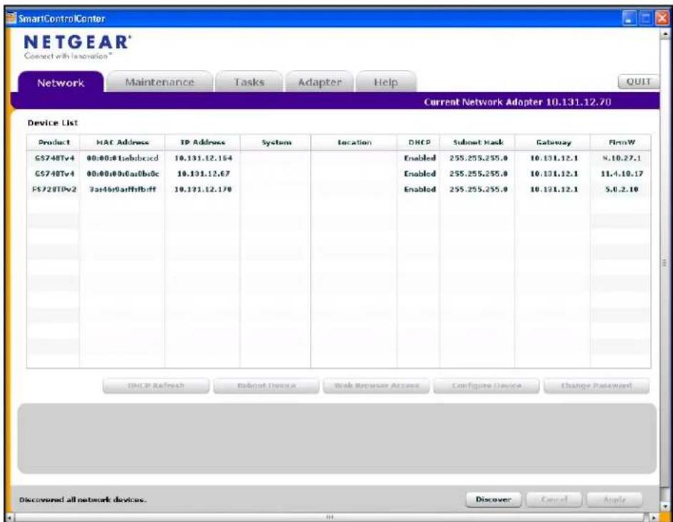
Figure 1. Smart Switch Discovery
- Make a note of the displayed IP address assigned by the DHCP server. You will need this value to access the switch directly from a Web browser (without using the Smart Control Center).
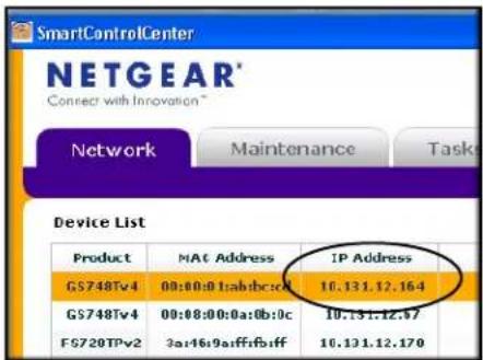
- Select your switch by clicking the line that displays the switch, then click the Web Browser Access button. The Smart Control Center displays a login window.
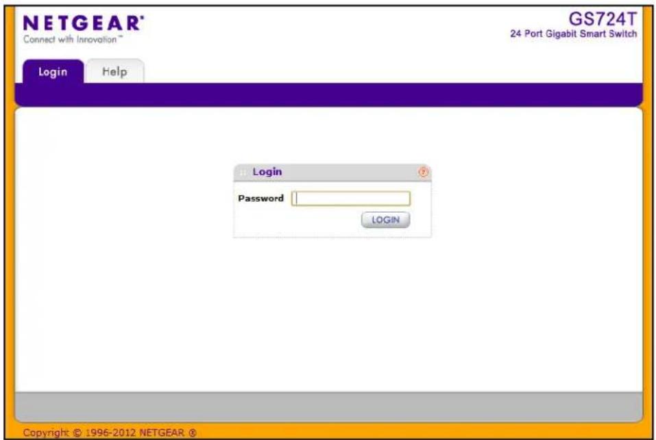
Use your Web browser to manage your switch. The default password is password. Then use this page to proceed to management of the switch covered in Web Interface on page 23.
Switch Discovery in a Network without a DHCP Server
This section describes how to use the Smart Control Center to set up your switch in a network without a DHCP server. If your network has no DHCP service, you must assign a static IP address to your switch. If you choose, you can assign it a static IP address, even if your network has DHCP service.
To assign a static IP address:
- Connect the switch to your existing network.
- Power on the switch by connecting its power cord.
- Install the Smart Control Center on your computer.
- Start the Smart Control Center.
- Click Discover for the Smart Control Center to find your GS716T and GS724T switch. The utility broadcasts Layer 2 discovery packets within the broadcast domain to discover the switch. You should see a screen similar to Figure 1 on page 12.
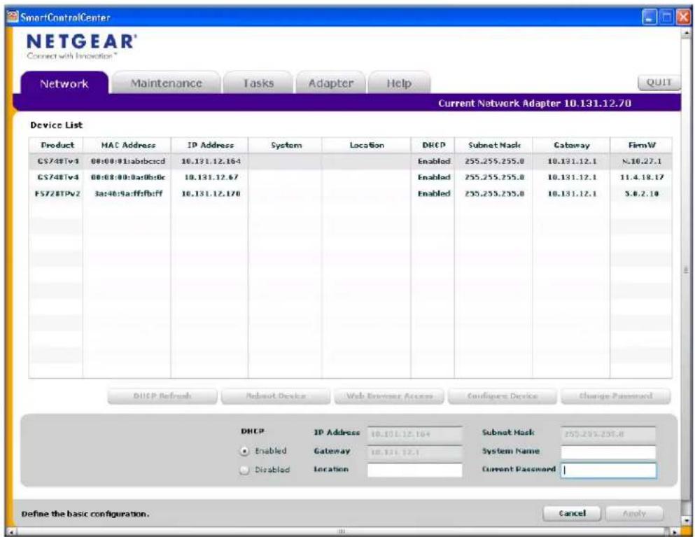
- Select the switch, then click Configure Device. The page expands to display additional fields at the bottom of the page, as the following figure shows.
-
Choose the Disabled radio button to disable DHCP.
-
Enter the static switch IP address, gateway IP address, and subnet mask for the switch, and then type your password.
Tip: You must enter the current password every time you use the Smart Control Center to update the switch setting. The default password is password.
- Click Apply to configure the switch with the network settings.
Please ensure that your PC and the switch are in the same subnet. Make a note of these settings for later use.
Network Settings Configuration on the Administrative System
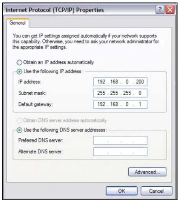
If you choose not to use the Smart Control Center to configure the network information on the switch, you can connect directly to the switch from an administrative system, such as a PC or laptop computer. The IP address of the administrative system must be in the same subnet as the default IP address on the switch. For most networks, this means you must change the IP address of the administrative system to be on the same subnet as the default IP address of the switch (192.168.0.239).
To change the IP address on an administrative system running a Microsoft® Windows® operating system, open the Internet Protocol (TCP/IP) properties screen that you access from the Local Area Connection properties, as shown in the following figure. You need Windows Administrator privileges to change these settings.

WARNING:
When you change the IP address of your administrative system, you will lose your connection to the rest of the network. Be sure to write down your current network address settings before you change them.
To modify the network settings on your administrative system:
- On your PC, access the MS Windows operating system TCP/IP Properties.
- Set the IP address of the administrative system to an address in the 192.168.0.0 network, such as 192.168.0.200. The IP address must be different from that of the switch but within the same subnet.
- Click OK.
To configure a static address on the switch: - Use a straight-through cable to connect the Ethernet port on the administrative system directly to any port on the GS716T and GS724T.
- Open a Web browser on your PC and connect to the management interface as described in Web Access on page 16.
- Change the network settings on the switch to match those of your network (this procedure is described in IP Configuration on page 33).
After you change the network settings on the switch, return the network configuration on your administrative system to the original settings.
Web Access
To access the GS716T and GS724T management interface, use one of the following methods:
• From the Smart Control Center, select the switch and click Web Browser Access.
- Open a Web browser and enter the IP address of the switch in the address field.
You must be able to ping the IP address of the GS716T and GS724T management interface from your administrative system for Web access to be available. If you used the Smart Control Center to set up the IP address and subnet mask, either with or without a DHCP server, use that IP address in the address field of your Web browser. If you did not change the IP address of the switch from the default value, enter 192.168.0.239 into the address field.
Clicking Web Browser Access on the Smart Control Center or accessing the switch directly from your Web browser displays the login screen shown in the following figure.
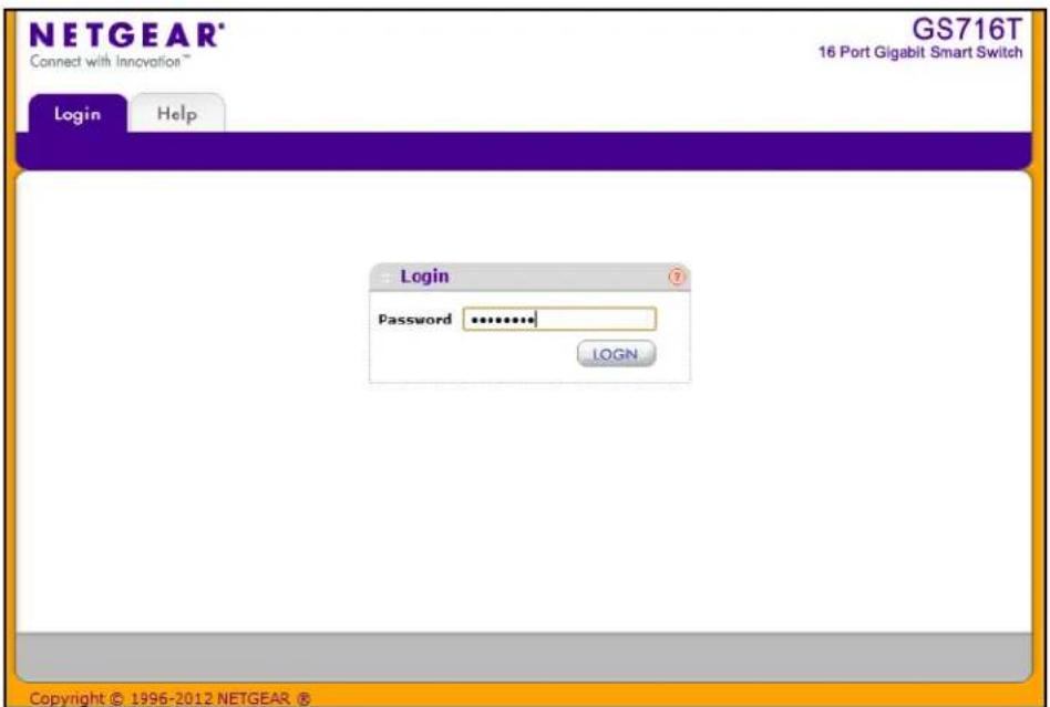
Figure 2. Login Screen
Smart Control Center Utilities
In addition to device discovery and network address assignment, the Smart Control Center includes several maintenance features. This section describes the following Smart Control Center utilities:
• Network Utilities on page 17
- Configuration Upload and Download on page 19
• Firmware Upgrade on page 20
• Viewing and Managing Tasks on page 22
Network Utilities
From the Network tab, you can perform the following functions:
- DHCP Refresh—Forces the switch to release the current bindings and request new address information from the DHCP server.
- Reboot Device—Reboots the selected device.
-
Web Browser Access—Launches a Web browser and connects to the management interface for the selected device.
-
Configure Device—Allows you to modify network information for the switch, including the IP address, DHCP client mode, system name, and location. For more information about this feature, see Configuring the Device.
- Change Password—Allows you to set a new password for the device. For more information about this feature, see Changing the Switch Password.
Configuring the Device
To modify switch information:
- Select the switch.
- Click Configure Device. Additional fields appear on the screen.

- To assign or update a static IP address, default gateway, or subnet mask, disable the DHCP client and enter the new information. You can also specify a system name and location for the switch.
- Type the password in the Current Password field. You cannot apply the changes without a valid switch password. The default password for the switch is password.
- Click Apply to update the switch with the changes to the network information.
Changing the Switch Password
- Select the switch.
- Click Change Password. Additional fields appear on the screen.

- Type the switch password in the Current Password field. The default password for the switch is password.
- Type the new password in the New Password and Confirm Password fields. The password can contain up to 20 ASCII characters.
Click Apply to update the switch with the new password.
Configuration Upload and Download
When you make changes to the switch, the configuration information is stored in a file on the switch. You can backup the configuration by uploading the configuration file from the switch to an administrative system. You can download a saved configuration file from the administrative system to the switch. The configuration file you download to the switch overwrites the running configuration on the switch.
Configuration upload and download is useful if you want to save a copy of the current switch configuration (Upload Configuration) before you make changes. If you do not like the changes, you can use the Download Configuration option to restore the switch to the settings in the saved configuration file.
To save a copy of the current switch configuration on your administrative system:
- Click the Maintenance tab and select the device with the configuration to save.
- Click Upload Configuration.
- From the Browse for Folder window that appears, navigate to and select the folder where you want to store the configuration file.
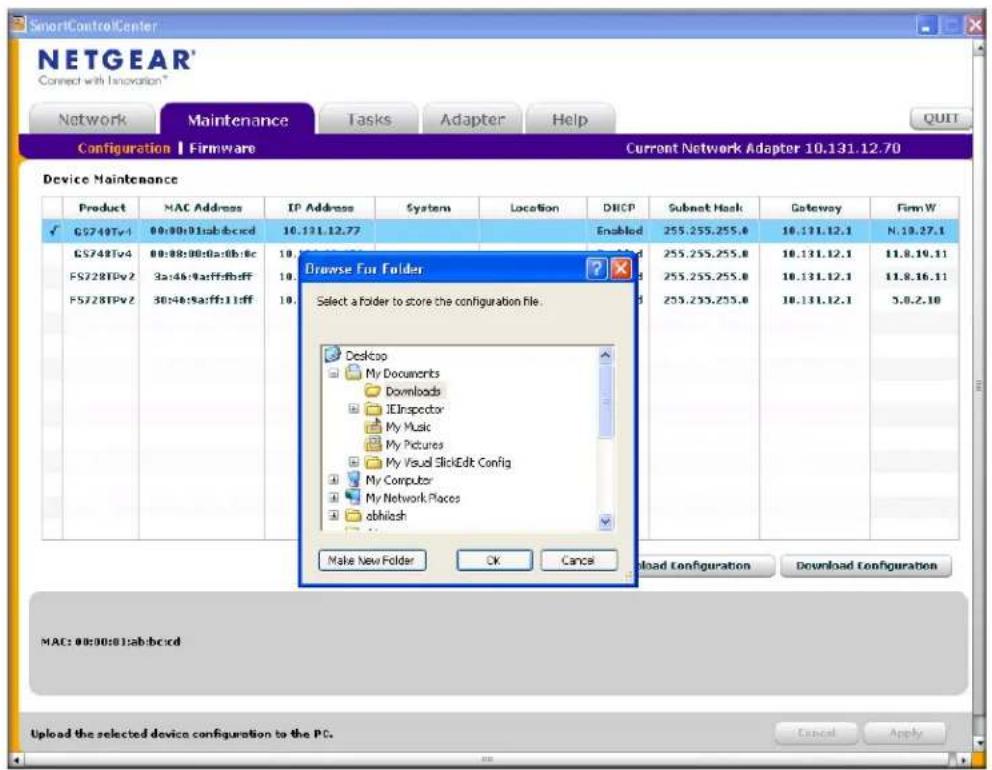
- Click OK.
- Enter the switch password and click Apply.
The file is uploaded to the administrative computer as a *.cfg file. You can open it and view the contents with a text editor.
To restore the configuration to a previously saved version:
-
Click the Maintenance tab and select the device with the configuration to restore.
-
Click Download Configuration.
-
From the Select a Configuration window that appears, navigate to and select the configuration file to download to the switch.
-
Click Open.
Optionally, you can schedule a different date and time to download the configuration file. To delay the download process, clear the Run Now? check box and enter a date and time to complete the download.

- Enter the switch password and click Apply to begin the download process.
Note: Click the Tasks tab to view status information about the configuration download.
Firmware Upgrade
The application software for the GS716T and GS724T Smart Switches is upgradable, enabling your switch to take advantage of improvements and additional features as they become available. The upgrade procedure and the required equipment are described in this section. This procedure assumes that you have downloaded or otherwise obtained the firmware upgrade and that you have it available as a binary file on your computer. This procedure uses the TFTP protocol to implement the transfer from computer to switch.
Note: You can also upgrade the firmware using the TFTP Download and HTTP Download features mentioned in this book. See HTTP File Upload on page 256.
To upgrade your firmware:
-
Click the Maintenance tab, and then click the Firmware link directly below the tabs (see Figure 1 on page 12).
-
Select the switch to upgrade and click Download Firmware.
By default, the firmware is downloaded to primary storage and will be become the active image after the download completes and the switch reboots. To download firmware to use as a backup image, select the Secondary Storage option. To prevent the switch from using the downloaded firmware as the active image, make sure the Run this FW after download option is clear.
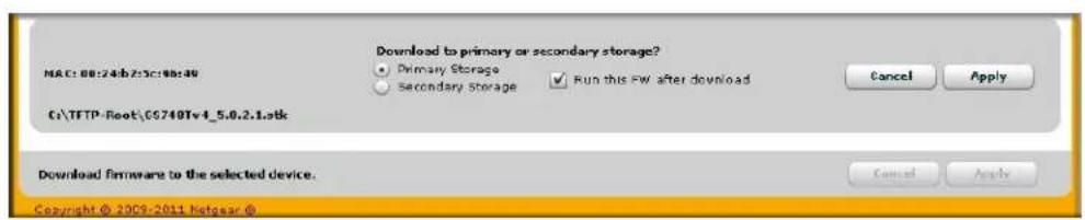
Note: NETGEAR recommends that you download the same image as the primary and secondary image for redundancy.
- From the Select new firmware window that appears, navigate to and select the firmware image to download to the switch.
- Click Open.
You can choose to schedule a later time to complete the download and installation by clearing the Run Now? option and selecting a date and time to perform the firmware download and installation. The scheduled firmware download appears in the Tasks list.
- Enter the switch password to continue downloading the firmware.
- Click Apply to download the firmware and upgrade the switch with the new image.
- When the process is complete, the switch automatically reboots.
Note: Click the Tasks tab to view status information about the firmware upgrade.

WARNING:
It is important that you do not power-off the administrative system or the switch while the firmware upgrade is in progress.
Viewing and Managing Tasks
From the Tasks tab, you can view information about configuration downloads and firmware upgrades that have already occurred, are in progress, or are scheduled to take place at a later time. You can also delete or reschedule selected tasks. Figure 3 shows the Tasks page.
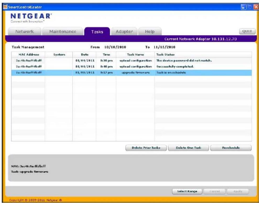
Figure 3. Tasks Page
The following list describes the command buttons that are specific to the Tasks page:
- Delete Task—Remove a completed or schedule task from the list.
- Reschedule—Change the scheduled date and time for a pending firmware upgrade.
- Select Range—Select all tasks that occurred or are scheduled to occur within a certain period of time.
User Interfaces
The GS716T and GS724T Smart Switches software includes a set of comprehensive management functions for configuring and monitoring the system by using one of the following methods:
- Web user interface
- Simple Network Management Protocol (SNMP)
Each of the standards-based management methods allows you to configure and monitor the components of the GS716T and GS724T Smart Switches software. The method you use to manage the system depends on your network size and requirements, and on your preference.
The GS716Tv2 and GS724Tv3 Software Administration Manual describes how to use the Web-based interface to manage and monitor the system.
Web Interface
To access the switch by using a Web browser, the browser must meet the following software requirements:
• HTML version 4.0, or later
- HTTP version 1.1, or later
- Java Runtime Environment 1.6 or later
Use the following procedures to log on to the Web interface:
- Open a Web browser and enter the IP address of the switch in the Web browser address field.
- The factory default password is password. Type the password into the field on the login screen, as shown in Figure 2 on page 17, and then click Login. Passwords are case sensitive.
- After the system authenticates you, the System Information page displays.
Figure 4 on page 24 shows the layout of the GS716T and GS724T switch Web interface.
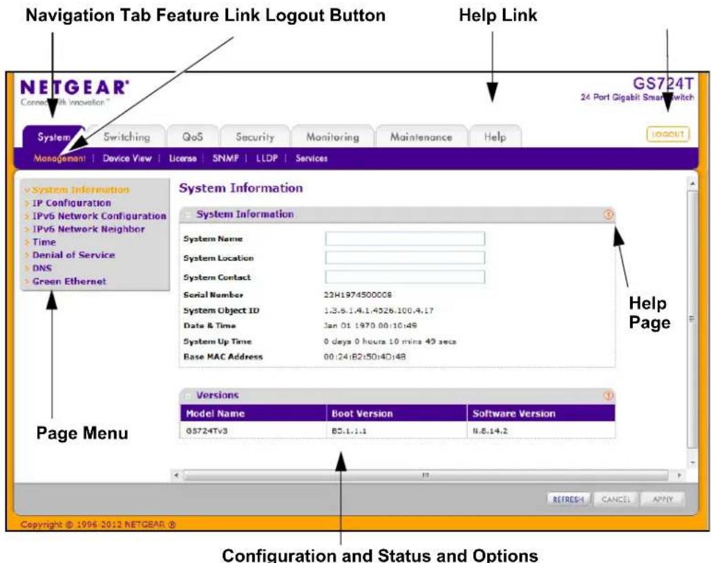
Figure 4. Administrative Page Layout
Navigation Tabs, Feature Links, and Page Menu
The navigation tabs along the top of the Web interface give you quick access to the various switch functions. The tabs are always available and remain constant, regardless of which feature you configure.
When you select a tab, the features for that tab appear as links directly under the tabs. The feature links in the blue bar change according to the navigation tab that is selected.
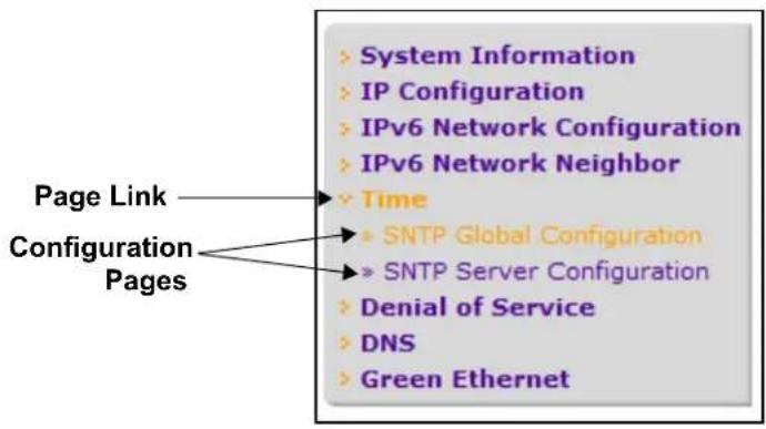
The configuration pages for each feature are available as links in the page menu on the left side of the page. Some items in the menu expand to reveal multiple configuration pages, as Figure 5 on page 25 shows. When you click a menu item that includes multiple configuration pages, the item becomes preceded by a down arrow symbol and expands to display the additional pages.
flowchart
graph TD
    A["Page Link"] --> B["System Information"]
    A --> C["IP Configuration"]
    A --> D["IPv6 Network Configuration"]
    A --> E["IPv6 Network Neighbor"]
    A --> F["Time"]
    F --> G["SNTP Global Configuration"]
    F --> H["SNTP Server Configuration"]
    F --> I["Denial of Service"]
    F --> J["DNS"]
    F --> K["Green Ethernet"]
Figure 5. Menu Hierarchy
Configuration and Status Options
The area directly under the feature links and to the right of the page menu displays the configuration information or status for the page you select. On pages that contain configuration options, you can input information into fields or select options from drop-down menus.
Each page contains access to the HTML-based help that explains the fields and configuration options for the page. Each page also contains command buttons.
The following table shows the command buttons that are used throughout the pages in the Web interface:
| Button Function | |
| Add Clicking Add adds the new item configured in the heading row of a table. | |
| Apply Clicking the Apply button sends the updated configuration to the switch. Configuration changes take effect immediately. | |
| Cancel | Clicking Cancel cancels the configuration on the screen and resets the data on the screen to the latest value of the switch. |
| Delete Clicking Delete removes the selected item. | |
| Refresh | Clicking the Refresh button refreshes the page with the latest information from the device. |
| Logout Clicking the Logout button ends the session. | |
Device View
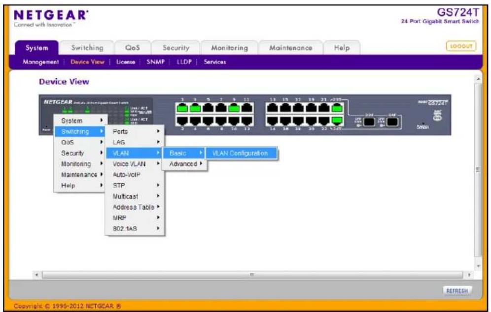
The Device View is a Java® applet that displays the ports on the switch. This graphic provides an alternate way to navigate to configuration and monitoring options. The graphic also provides information about device ports, current configuration and status, table information, and feature components.
The Device View is available from the System > Device View page.
Depending upon the status of the port, the LED of the port illuminates either red, green, or yellow:
• A red LED indicates that the link is disabled.
- A green LED indicates that the port is enabled and operating at a transfer rate of 1000 Mbps.
- A yellow LED indicates that the port is enabled and operating at a transfer rate of 10 Mbps/100 Mbps.
The following image shows the Device View of the GS716T.

The following image shows the Device View of the GS724T.

Click the port you want to view or configure to see a menu that displays statistics and configuration options. Click the menu option to access the page that contains the configuration or monitoring options.
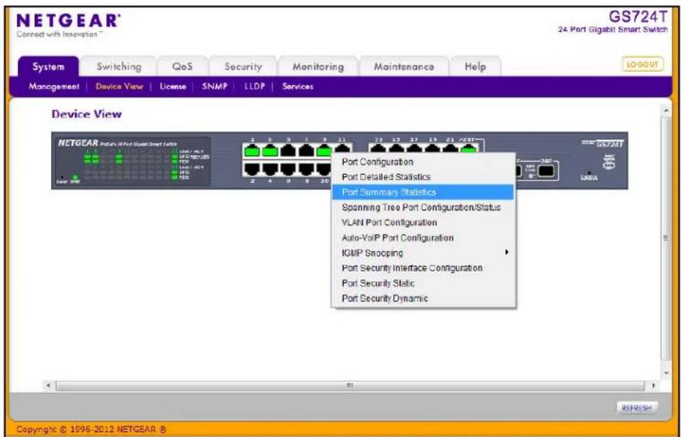
If you click the graphic, but do not click a specific port, the main menu appears, as the following figure shows. This menu contains the same option as the navigation tabs at the top of the page.
Help Page Access
Every page contains a link to the online help, which contains information to assist in configuring and managing the switch. The online help pages are context sensitive. For example, if the IP Addressing page is open, the help topic for that page displays if you click Help. Figure 4 on page 24 shows the location of the Help link on the Web interface.
User-Defined Fields
User-defined fields can contain 1 to 159 characters, unless otherwise noted on the configuration Web page. All characters may be used except for the following (unless specifically noted in for that feature):
| <
| > |
*    |
?
SNMP Management
The GS716T and GS724T Smart Switches software supports the configuration of SNMP groups and users that can manage traps that the SNMP agent generates. The switches use both standard public MIBs for standard functionality and private MIBs that support additional switch functionality. All private MIBs begin with a “-” prefix. The main object for interface configuration is in -SWITCHING-MIB, which is a private MIB. Some interface configurations also involve objects in the public MIB, IF-MIB.
SNMP is enabled by default. The System > Management > System Information Web page, which is the page that displays after a successful login, displays the information you need to configure an SNMP manager to access the switch.
Any user can connect to the switch using the SNMPv3 protocol, but for authentication and encryption, the switch supports only one user which is admin; therefore there is only one profile that can be created or modified.
To configure authentication and encryption settings for the SNMPv3 admin profile by using the Web interface:
- Navigate to the System > SNMP > SNMPv3 > User Configuration page.
- To enable authentication, select an Authentication Protocol option, which is either MD5 or SHA.
- To enable encryption, select the DES option in the Encryption Protocol field. Then, enter an encryption code of eight or more alphanumeric characters in the Encryption Key field.
- Click Apply.
To access configuration information for SNMPv1 or SNMPv2, click System > SNMP > SNMPv1/v2 and click the page that contains the information to configure.
Interface Naming Convention
The GS716T and GS724T Smart Switches supports physical and logical interfaces. Interfaces are identified by their type and the interface number. All the physical ports 1–48 are Gigabit ports and the SFP Ports 47–50 support 1000M Speed fiber modules. Ports 47–48 are Combo ports and ports 49–50 will support dedicated SFP modules. The number of the port is identified on the front panel. You can configure the logical interfaces by using the software. The following table describes the naming convention for all interfaces available on the switch.
| Interface Description Example | ||
| Physical The physical ports include Gigabit ports and are numbered sequentially starting from one. | g1, g2, g3 | |
| Link Aggregation Group (LAG) | LAG interfaces are logical interfaces that are only used for bridging functions. | l1, l2, l3 |
| CPU Management Interface This is the internal switch interface responsible for the switch base MAC address. This interface is not configurable and is always listed in the MAC Address Table. | c1 | |
GS716T and GS724T Gigabit Smart Switches
System Information Features
2
Use the features in the System tab to define the switch's relationship to its environment. The System tab contains links to the following features:
• Management on page 31
- License on page 56
- SNMP on page 58
- LLDP on page 63
• Services — DHCP Filtering on page 76
Management
This section describes how to display the switch status and specify some basic switch information, such as the management interface IP address, system clock settings, and DNS information. From the Management link, you can access the following pages:
• System Information on page 32
• IP Configuration on page 33
• IPv6 Network Neighbor on page 37
• Time on page 38
• Denial of Service on page 44
- DNS on page 47
• Green Ethernet on page 49
• IPv6 Network Configuration on page 35
System Information
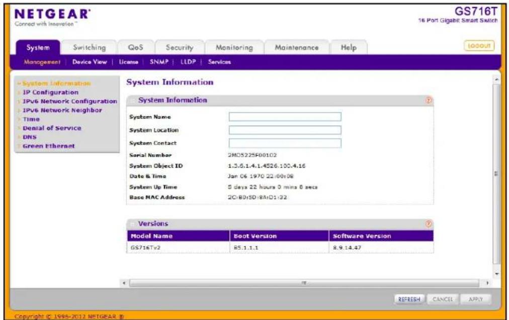
After a successful login, the System Information page displays. Use this page to configure and view general device information.
To display the System Information page, click System > Management > System Information. A screen similar to the following displays.
To define system information:
- Open the System Information page.
-
Define the following fields:
-
System Name. Enter the name you want to use to identify this switch. You may use up to 31 alphanumeric characters. The factory default is blank.
- System Location. Enter the location of this switch. You may use up to 31 alphanumeric characters. The factory default is blank.
-
System Contact. Enter the contact person for this switch. You may use up to 31 alphanumeric characters. The factory default is blank.
-
Click Apply.
The system parameters are applied, and the device is updated.
The following table describes the status information the System Page displays.
| Field Description | |
| Serial Number The serial number of the switch. | |
| System Object ID The base object ID for the switch's enterprise MIB. | |
| Date & Time The current date and time. | |
| System Up Time Displays the number of days, hours, and minutes since the last system restart. | |
| Base MAC Address The universally assigned network address. | |
| Model Name The model name of the switch. | |
| Boot Version The boot code version of the switch. | |
| Software Version The software version of the switch. | |
IP Configuration
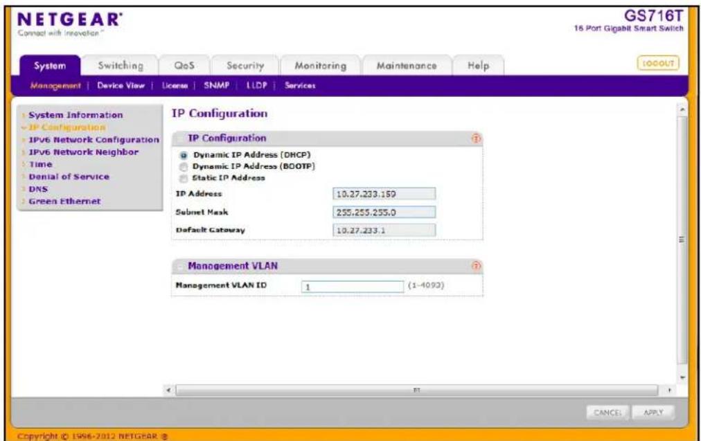
Use the IP Configuration page to configure network information for the management interface, which is the logical interface used for in-band connectivity with the switch through any of the switch's front panel ports. The configuration parameters associated with the switch's network interface do not affect the configuration of the front panel ports through which traffic is switched or routed.
To access the page, click System > Management > IP Configuration. A screen similar to the following displays.
To configure the network information for the management interface:
-
Select the appropriate radio button to determine how to configure the network information for the switch management interface:
-
Dynamic IP Address (DHCP). Specifies that the switch must obtain the IP address through a DHCP server.
- Dynamic IP Address (BOOTP). Specifies that the switch must obtain the IP address through a BootP server.
-
Static IP Address. Specifies that the IP address, subnet mask, and default gateway must be manually configured. Enter this information in the fields below this radio button.
-
If you selected the Static IP Address option, configure the following network information:
-
IP Address. The IP address of the network interface. The factory default value is 192.168.0.239. Each part of the IP address must start with a number other than zero. For example, IP addresses 001.100.192.6 and 192.001.10.3 are not valid.
- Subnet Mask. The IP subnet mask for the interface. The factory default value is 255.255.255.0.
-
Default Gateway. The default gateway for the IP interface. The factory default value is 192.168.0.254.
-
Specify the VLAN ID for the management VLAN.
The management VLAN is used to establish an IP connection to the switch from a workstation that is connected to a port in the same VLAN. If not specified, the active management VLAN ID is 1 (default), which allows an IP connection to be established through any port.
When the management VLAN is set to a different value, an IP connection can be made only through a port that is part of the management VLAN. It is also mandatory that the port VLAN ID (PVID) of the port to be connected in that management VLAN be the same as the management VLAN ID.
The management VLAN has the following requirements:
- Only one management VLAN can be active at a time.
- When a new management VLAN is configured, connectivity through the existing management VLAN is lost.
- The management station should be reconnected to the port in the new management VLAN.
Note: Make sure that the VLAN to be configured as the management VLAN exists. And make sure that the PVID of at least one port that is a port of the VLAN is the same as the management VLAN ID. For information about creating VLANs and configuring the PVID for a port, see VLANs on page 89.
-
If you change any of the network connection parameters, click Apply to apply the changes to the system.
-
Click Cancel to cancel the configuration on the screen and reset the data on the screen to the latest value of the switch.
IPv6 Network Configuration
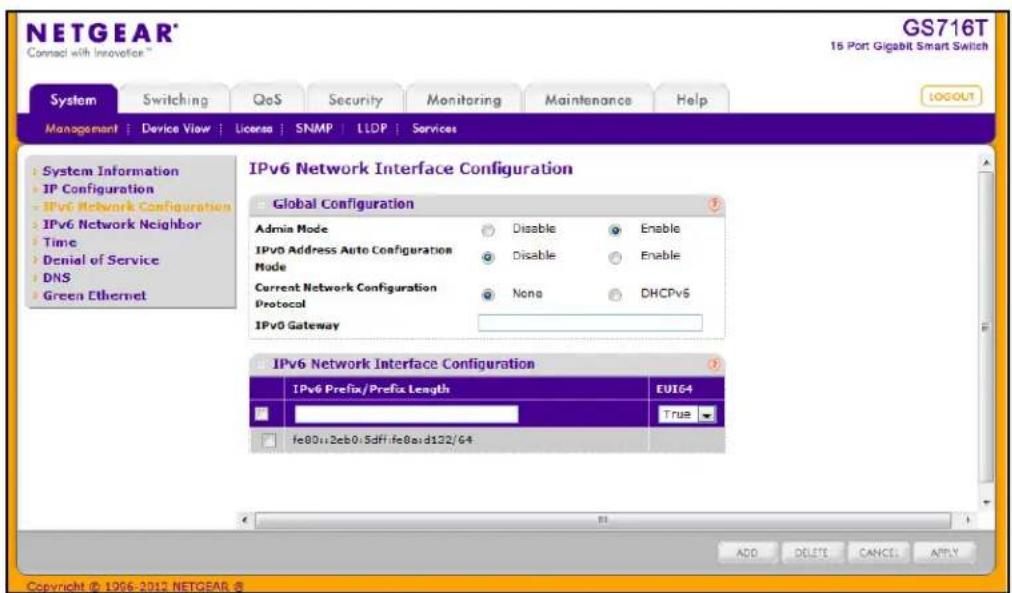
Use the IPv6 Network Configuration page to configure the IPv6 network interface, which is the logical interface used for in-band connectivity with the switch via all of the switch's front-panel ports. The configuration parameters associated with the switch's network interface do not affect the configuration of the front-panel ports through which traffic is switched or routed.
To access the page, click System > Management > IPv6 Network Configuration. A screen similar to the following displays.
To access the switch over an IPv6 network, you must initially configure the switch with IPv6 information (IPv6 prefix, prefix length, and default gateway). IPv6 can be configured using any of the following options:
• IPv6 Auto Configuration
- DHCPv6
When in-band connectivity is established, IPv6 information can be changed using any of the following:
• SNMP-based management
• Web-based management
To configure the network information for an IPv6 network:
- Admin Mode. Enable or disable the IPv6 network interface on the switch. The default value is Enable.
- IPv6 Address Auto Configuration Mode. The IPv6 address for the IPv6 network interface is set in auto configuration mode if this option is enabled. The default value is Disable. Auto configuration can be enabled only when DHCPv6 is not enabled on any of the management interfaces.
- Current Network Configuration Protocol. The IPv6 address for the IPv6 network interface is configured by DHCPv6 protocol if this option is enabled. The default value is None. DHCPv6 can be enabled only when IPv6 Auto config or DHCPv6 are not enabled on any of the management interfaces.
- DHCPv6 Client DUID. Identifier used to identify the client's unique DUID value. This option only displays when DHCPv6 is enabled.
- IPv6 Gateway. Specify the gateway for the IPv6 network interface. The gateway address is in IPv6 global or link-local address format.
- IPv6 Prefix/Prefix Length. Add the IPv6 prefix and prefix length to the IPv6 network interface. The address is in the global address format.
- EUI64. Specify whether format IPv6 address in EUI-64 format. The default value is False.
- Click Add to add a new IPv6 address in global format.
- Click Delete to delete a selected IPv6 address.
- Click Apply to apply the changes to the system.
- Click Cancel to cancel the configuration on the screen and reset the data on the screen to the latest value of the switch.
IPv6 Network Neighbor
Use the IPv6 Network Neighbor page to configure the IPv6 Network Interface IPv6 Neighbor Table.
To access the page, click System > Management > IPv6 Network Neighbor. A screen similar to the following displays.
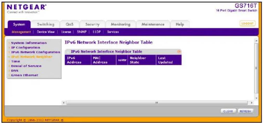
Click Clear to delete all entries from the table. The table is repopulated as the IPv6 neighbors are discovered on the network. Click Refresh to refresh the screen with most recent data.
The following table describes the information the IPv6 Network Interface Neighbor Table displays
| Field Description | |
| IPv6 Address Specifies the IPv6 address of neighbor or interface. | |
| MAC Address Specifies MAC address associated with an interface. | |
| IsRtr Indicates whether the neighbor is a router. If the neighbor is a router, the value is True. If the neighbor is not a router, the value is False. | |
| Neighbor State Specifies the state of the neighbor cache entry. The following are the states for dynamic entries in the IPv6 neighbor discovery cache:Reachable. Positive confirmation was received within the last Reachable Time milliseconds that the forward path to the neighbor was functioning properly. While in REACH state, the device takes no special action as packets are sent.Stale. More than ReachableTime milliseconds have elapsed since the last positive confirmation was received that the forward path was functioning properly. While in STALE state, the device takes no action until a packet is sent.Delay. More than ReachableTime milliseconds have elapsed since the last positive confirmation was received that the forward path was functioning properly. A packet was sent within the last DELAY_FIRST_PROBE_TIME seconds. If no reachability confirmation is received within DELAY_FIRST_PROBE_TIME seconds of entering the DELAY state, send a neighbor solicitation message and change the state to PROBE.Probe. A reachability confirmation is actively sought by resending neighbor solicitation messages every RetransTimer milliseconds until a reachability confirmation is received.Unknown. The switch cannot determine the state of the cache entry. | |
| Last Updated. Time since the address was confirmed to be reachable. | |
Time
GS716T and GS724T Smart Switches software supports the Simple Network Time Protocol (SNTP). You can also set the system time manually
SNTP assures accurate network device clock time synchronization up to the millisecond. Time synchronization is performed by a network SNTP server. GS716T and GS724T Smart Switches software operates only as an SNTP client and cannot provide time services to other systems.
Time sources are established by Stratums. Stratums define the accuracy of the reference clock. The higher the stratum (where zero is the highest), the more accurate the clock. The device receives time from stratum 1 and above since it is itself a stratum 2 device.
The following is an example of stratums:
- Stratum 0: A real-time clock is used as the time source, for example, a GPS system.
- Stratum 1: A server that is directly linked to a Stratum 0 time source is used. Stratum 1 time servers provide primary network time standards.
- Stratum 2: The time source is distanced from the Stratum 1 server over a network path. For example, a Stratum 2 server receives the time over a network link, via NTP, from a Stratum 1 server.
Information received from SNTP servers is evaluated based on the time level and server type.
SNTP time definitions are assessed and determined by the following time levels:
• T1: Time at which the original request was sent by the client.
• T2: Time at which the original request was received by the server.
• T3: Time at which the server sent a reply.
• T4: Time at which the client received the server's reply.
The device can poll Unicast server types for the server time.
Polling for Unicast information is used for polling a server for which the IP address is known. SNTP servers that have been configured on the device are the only ones that are polled for synchronization information. T1 through T4 are used to determine server time. This is the preferred method for synchronizing device time because it is the most secure method. If this method is selected, SNTP information is accepted only from SNTP servers defined on the device using the SNTP Server Configuration page.
The device retrieves synchronization information, either by actively requesting information or at every poll interval.
Time Configuration
Use the Time Configuration page to view and adjust date and time settings.
To display the Time Configuration page, click System > Management > Time > SNTP Global Configuration.
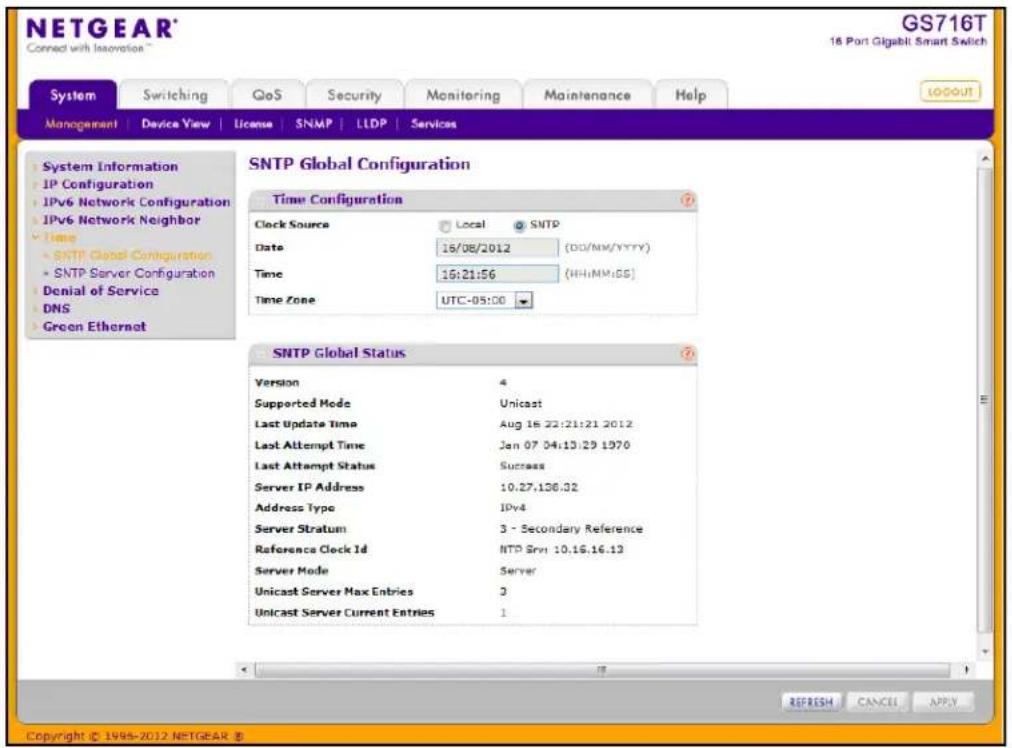
To configure the time by using the CPU clock cycle as the source:
- From the Clock Source field, select Local.
- In the Date field, enter the date in the DD/MM/YYYY format.
- In the Time field, enter the time in HH:MM:SS format.
Note: If you do not enter a date and time, the switch will calculate the date and time using the CPU's clock cycle.
When the Clock Source is set to Local, the Time Zone field is grayed out (disabled):
- Click Apply to send the updated configuration to the switch. Configuration changes occur immediately.
To configure the time through SNTP:
- From the Clock Source field, select SNTP.
When the Clock Source is set to SNTP, the Date and Time fields are grayed out (disabled). The switch gets the date and time from the network. - Use the menu to select the Coordinated Universal Time (UTC) time zone in which the switch is located, expressed as the number of hours.
- Click Apply to send the updated configuration to the switch. Configuration changes take effect immediately.
- Use the SNTP Server Configuration page to configure the SNTP server settings, as described in SNTP Server Configuration on page 42.
- Click Refresh to refresh the page with the most current data from the switch.
- Click Cancel to cancel the configuration on the screen and reset the data on the screen to the latest value of the switch.
The SNTP Global Status table on the Time Configuration page displays information about the system's SNTP client. The following table describes the SNTP Global Status fields.
| Field Description | |
| Version Specifies the SNTP Version the client supports. | |
| Supported Mode Specifies the SNTP modes the client supports. Multiple modes may be supported by a client. | |
| Last Update Time Specifies the local date and time (UTC) the SNTP client last updated the system clock. | |
| Last Attempt Time Specifies the local date and time (UTC) of the last SNTP request or receipt of an unsolicited message. | |
| Last Attempt Status | Specifies the status of the last SNTP request or unsolicited message for both unicast mode. If no message has been received from a server, a status of Other is displayed. These values are appropriate for all operational modes:Other: None of the following enumeration values.Success: The SNTP operation was successful and the system time was updated.Request Timed Out: A directed SNTP request timed out without receiving a response from the SNTP server.Bad Date Encoded: The time provided by the SNTP server is not valid.Version Not Supported: The SNTP version supported by the server is not compatible with the version supported by the client.Server Unsynchronized: The SNTP server is not synchronized with its peers. This is indicated via the 'leap indicator' field on the SNTP message.Server Kiss Of Death: The SNTP server indicated that no further queries were to be sent to this server. This is indicated by a stratum field equal to 0 in a message received from a server. |
| Server IP Address | Specifies the IP address of the server for the last received valid packet. If no message has been received from any server, an empty string is shown. |
| Address Type Specifies the address type of the SNTP Server address for the last received valid packet. | |
| Server Stratum Specifies the claimed stratum of the server for the last received valid packet. | |
| Reference Clock Id | Specifies the reference clock identifier of the server for the last received valid packet. |
| Server Mode Specifies the mode of the server for the last received valid packet. | |
| Unicast Sever Max Entries Specifies the maximum number of unicast server entries that can be configured on this client. | |
| Unicast Server Current Entries | Specifies the number of current valid unicast server entries configured for this client. |
Click Refresh to refresh the page with the most current data from the switch.
SNTP Server Configuration
Use the SNTP Server Configuration page to view and modify information for adding and modifying Simple Network Time Protocol SNTP servers.
To display the SNTP Server Configuration page, click System > Management > Time > SNTP Server Configuration.
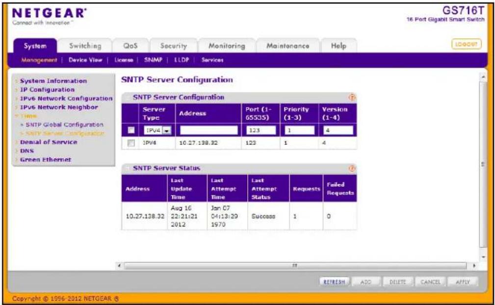
To configure a new SNTP Server:
-
Enter the appropriate SNTP server information in the available fields:
-
Server Type. Specifies whether the address for the SNTP server is an IP address (IPv4) or host name (DNS).
- Address. Enter the IP address or the host name of the SNTP server.
- Port. Enter a port number on the SNTP server to which SNTP requests are sent. The valid range is 1–65535. The default is 123.
- Priority. Specifies the priority of this server entry in determining the sequence of servers to which SNTP requests are sent. Enter a priority from 1–3, with 1 being the default and the highest priority. Servers with lowest numbers have priority.
-
Version. Enter the protocol version number that corresponds to the NTP version running on the SNTP server. The range is 1–4, and the default version is SNTPv4.
-
Click Add.
-
Repeat the previous steps to add additional SNTP servers. You can configure up to three SNTP servers.
-
To removing an SNTP server, select the check box next to the configured server to remove, and then click Delete. The entry is removed, and the device is updated.
-
To change the settings for an existing SNTP server, select the check box next to the configured server and enter new values in the available fields, and then click Apply. Configuration changes take effect immediately.
- Click Cancel to cancel the configuration on the screen and reset the data on the screen to the latest value of the switch.
The SNTP Server Status table displays status information about the SNTP servers configured on your switch. The following table describes the SNTP Global Status fields.
| Field Description | |
| Address Specifies all the | existing Server Addresses. If no Server configuration exists, a message saying “No SNTP server exists” flashes on the screen. |
| Last Update Time | Specifies the local date and time (UTC) that the response from this server was used to update the system clock. |
| Last Attempt Time | Specifies the local date and time (UTC) that this SNTP server was last queried. |
| Last Attempt Status | Specifies the status of the last SNTP request to this server. If no packet has been received from this server, a status of Other is displayed:Other: None of the following enumeration values.Success: The SNTP operation was successful and the system time was updated.Request Timed Out: A directed SNTP request timed out without receiving a response from the SNTP server.Bad Date Encoded: The time provided by the SNTP server is not valid.Version Not Supported: The SNTP version supported by the server is not compatible with the version supported by the client.Server Unsynchronized: The SNTP server is not synchronized with its peers. This is indicated via the 'leap indicator' field on the SNTP message.Server Kiss Of Death: The SNTP server indicated that no further queries were to be sent to this server. This is indicated by a stratum field equal to 0 in a message received from a server. |
| Requests Specifies the number of SNTP requests made to this server since last agent reboot. | |
| Failed Requests Specifies the number of failed SNTP requests made to this server since last reboot. | |
Click Refresh to refresh the page with the most current data from the switch.
Denial of Service
Use the Denial of Service (DoS) page to configure DoS control. The GS716T and GS724T switch provide support for classifying and blocking specific types of DoS attacks. The type of DoS attacks the switch can detect and prevent are described in DoS Configuration on page 45.
Auto-DoS Configuration
The Auto-DoS Configuration page lets you automatically enable all the DoS features available on the switch, except for TCP and UDP port attacks. See DoS Configuration on page 45 for information about the types of DoS attacks the switch can monitor and block.
Note: When Auto-DoS is enabled, a port that is under attack is automatically shut down and does not forward traffic. The port can be enabled only manually by the admin user. A warning message is logged to the buffered log and is sent to the Syslog server.
To access the Auto-DoS Configuration page, click System > Management > Denial of Service > Auto-DoS Configuration.
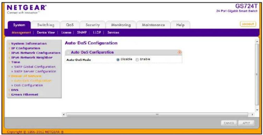
To configure the Auto-DoS feature:
- Select a radio button to enable or disable Auto-DoS:
- Disable. Auto-DoS is disabled (default).
- Enable. Auto-DoS is enabled.
-
Click Apply to send the updated configuration to the switch. Configuration changes occur immediately.
-
Click Cancel to cancel the configuration on the screen and reset the data on the screen to the latest value of the switch.
DoS Configuration
The DoS Configuration page lets you to select which types of DoS attacks for the switch to monitor and block.
To access the DoS Configuration page, click System > Management > Denial of Service > DoS Configuration.
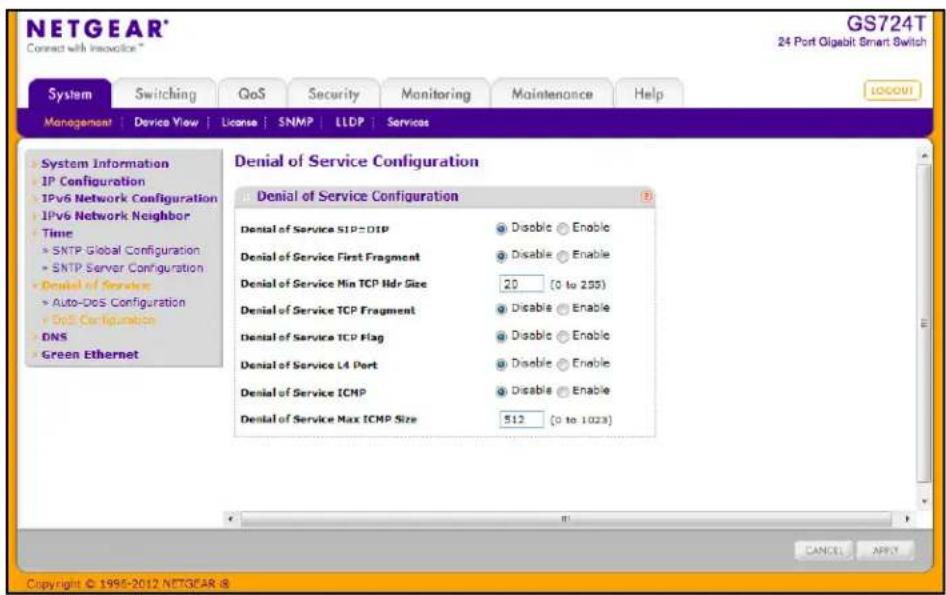
To configure individual DoS settings:
- Select the types of DoS attacks for the switch to monitor and block and configure any associated values, as the following list describes.
- Denial of Service SIP=DIP: Enable or disable this option by selecting the corresponding line on the radio button. Enabling SIP=DIP DoS prevention causes the switch to drop packets that have a source IP address equal to the destination IP address. The factory default is disabled.
- Denial of Service First Fragment: IP Fragment Offset = 1. Enable or disable this option by selecting the corresponding line on the radio button. Enabling First Fragment DoS prevention causes the switch to drop packets that have an IP fragment offset equal to 1. The factory default is disabled.
- Denial of Service Min TCP Hdr Size: Specifies the Min TCP Hdr Size allowed. If First TCP Fragment DoS prevention is enabled, then the switch will drop packets that have a TCP header smaller than this configured Min TCP Hdr Size. The factory default is 20.
- Denial of Service TCP Fragment: TCP Header size is smaller than the configured value. Enable or disable this option by selecting the corresponding line on the radio button. Enabling TCP Fragment DoS prevention causes the switch to drop packets that have a TCP header smaller than the configured Min TCP Hdr Size. The factory default is disabled.
- Denial of Service TCP Flag: Enable or disable this option by selecting the corresponding line on the radio button. Enabling TCP Flag DoS prevention causes the switch to drop packets that have TCP flag SYN set and TCP source port less than 1024 or TCP control flags set to 0 and TCP sequence number set to 0 or TCP flags FIN, URG, and PSH set and TCP sequence number set to 0 or both TCP flags SYN and FIN set. The factory default is disabled.
- Denial of Service L4 Port: Enable or disable this option by selecting the corresponding line on the radio button. Enabling L4 Port DoS prevention causes the switch to drop packets that have TCP/UDP source port equal to TCP/UDP destination port. The factory default is disabled.
- Denial of Service ICMP: Enable or disable this option by selecting the corresponding line on the radio button. Enabling ICMP DoS prevention causes the switch to drop ICMP packets that have a type set to ECHO_REQ (ping) and a size greater than the configured ICMP Pkt Size. The factory default is disabled.
-
Denial of Service Mx ICMP Pkt Size: If ICMP DoS prevention is enabled and if the ICMP echo request is carried in an unfragmented IPv4/IPv6 datagram and if the total length (in the IP header) indicates a value greater than MAX ICMP Size configured + IP header length, then the specified packet is dropped. The factory default is 512.
-
If you change any of the DoS settings, click Apply to apply the changes to the switch.
-
Click Cancel to cancel the configuration on the screen and reset the data on the screen to the latest value of the switch.
DNS
You can use these pages to configure information about DNS servers the network uses and how the switch operates as a DNS client.
DNS Configuration
Use this page to configure global DNS settings and DNS server information.
To access this page, click System > Management > DNS > DNS Configuration.
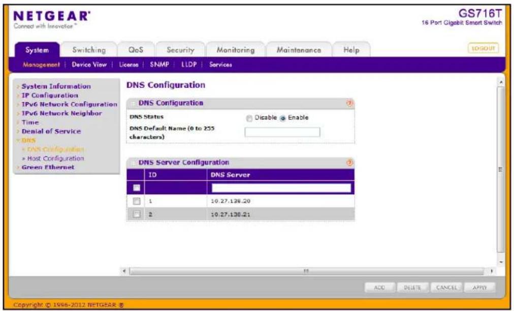
To configure the global DNS settings:
-
Specify whether to enable or disable the administrative status of the DNS Client.
-
Enable. Allow the switch to send DNS queries to a DNS server to resolve a DNS domain name. DNS is disabled by default.
-
Disable. Prevent the switch from sending DNS queries.
-
Enter the DNS default domain name to include in DNS queries. When the system is performing a lookup on an unqualified host name, this field is provided as the domain name (for example, if default domain name is netgear.com and the user enters test, then test is changed to test.netgear.com to resolve the name).
- To specify the DNS server to which the switch sends DNS queries, enter an IP address in standard IPv4 dot notation in the DNS Server Address and click Add. The server appears in the list below. You can specify up to eight DNS servers. The precedence is set in the order created.
-
To remove a DNS server from the list, select the check box next to the server you want to remove and click Delete. If no DNS server is specified, the check box is global and will delete all the DNS servers listed.
-
Click Cancel to cancel the configuration on the screen and reset the data on the screen to the latest value of the switch.
- Click Apply to send the updated configuration to the switch. Configuration changes take effect immediately.
Host Configuration
Use this page to manually map host names to IP addresses or to view dynamic DNS mappings.
To access this page, click System > Management > DNS > Host Configuration.
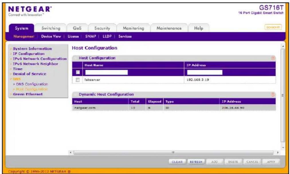
To add a static entry to the local DNS table:
- Specify the static host name to add. Each substring must be less than 64 characters in length separated by a dot or space, and the length of the whole string must not exceed 158 characters.
- Specify the IP address in standard IPv4 dot notation to associate with the host name.
- Click Add. The entry appears in the list below.
- To remove an entry from the static DNS table, select the check box next to the entry and click Delete.
- To change the host name or IP address in an entry, select the check box next to the entry and enter the new information in the appropriate field, and then click Apply.
- Click Cancel to cancel the configuration on the screen and reset the data on the screen to the latest value of the switch.
The Dynamic Host Configuration table shows host name-to-IP address entries that the switch has learned. The following table describes the dynamic host fields:
| Field Description | |
| Host Lists the host name you | assign to the specified IP address. |
| Total Amount of time since the | dynamic entry was first added to the table. |
| Elapsed Amount of time since | the dynamic entry was last updated. |
| Type The type of the dynamic entry. | |
| Addresses Lists the IP address | associated with the host name. |
Click Refresh to refresh the table with the most current data from the switch.
Click Clear to delete Dynamic Host Entries. The table will be repopulated with entries as they are learned.
Green Ethernet
The Green Ethernet features allow the switch to reduce power consumption on a per-port basis, except for the Combo ports (g15–16 for GS716T; g23–24 for GS724T). Each switch can support one or more of the following features:
- Energy-detect Mode - When the Energy Detect mode is enabled and the port link is down, the PHY automatically goes down for short period of time and then wakes up to check link pulses. This mode reduces power consumption on the port when no link partner is present.
- Short Cable Mode: With Short Cable mode enabled, the PHY goes into low power mode when the cable length is less than a certain limit.
Green Ethernet Configuration
Use this page to configure the administrative mode for the Green Ethernet features available on the switch. These features must also be enabled on each port to take advantage of the possible power savings.
To access this page, click System > Management > Green Ethernet Configuration.
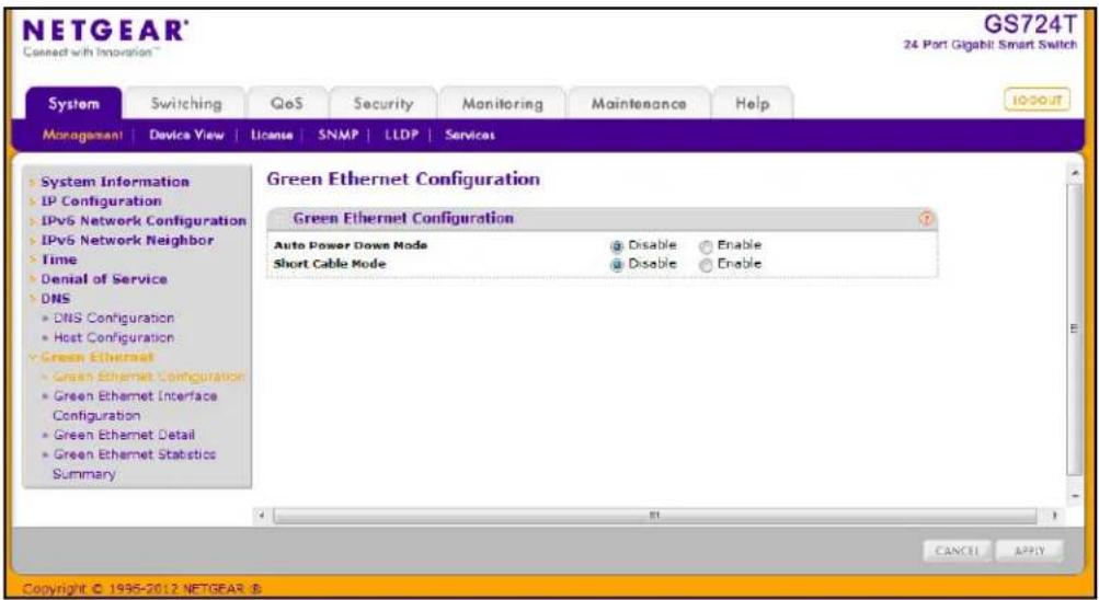
To configure the Green Ethernet feature:
-
Enable or disable the Auto Power Down Mode.
-
Enable. When the port link is down, the PHY will automatically go down for a short period of time and then wake up to check link pulses. This allows the port to continue to perform auto-negotiation while consuming less power when no link partner is present.
-
Disable. Provide full power to the port even if no link partner is present.
-
Enable or disable the Short Cable Mode.
-
Enable. The switch performs a cable test when the port link is up. If the cable that connects the port to its link partner has a length less than 10m, PHYs are placed in low-power mode (nominal power).
-
Disable. Do not perform an automatic cable test on a linked port or adjust the port power based on the cable length.
-
Click Apply to send the updated configuration to the switch. Configuration changes take effect immediately.
Green Ethernet Interface Configuration
Use this page to configure Green Ethernet features on a per-port basis. The Green Ethernet modes must be administratively enabled on the switch for the mode enabled on the port to take effect.
To access this page, click System > Management > Green Ethernet > Green Ethernet Interface Configuration.
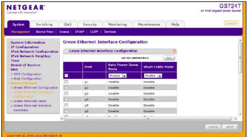
To configure the Green Ethernet Interface feature:
- Select the check box next to the port to configure. You can select multiple ports to apply the same setting to all selected ports. To configure all ports, select the check box in the heading row.
- Enable or disable the Auto Power-Down Mode.
- Enable. When the port link is down, the PHY automatically goes down for a short period of time and then wake up to check link pulses. This behavior saves power consumption when there is no link partner while still allowing the port to perform auto-negotiation if a link partner does become present.
- Disable. The PHY remains up even if no link partner is present.
-
Enable or disable the Short Cable Mode.
-
Enable. The switch performs a cable test on each cable connect to its ports. If the cable is less than 10m in length, the port is placed in low power mode (nominal power).
-
Disable. Full transmit power is provided to all ports, regardless of cable length.
-
Click Apply to apply the change to the system. Configuration changes take effect immediately.
-
Click Cancel to cancel the configuration on the screen and reset the data on the screen to the latest value of the switch.
Green Ethernet Detail
Use this page to configure Green Ethernet monitor and manage Green Ethernet features on a specific port.
To access this page, click System > Management > Green Ethernet > Green Ethernet Detail.
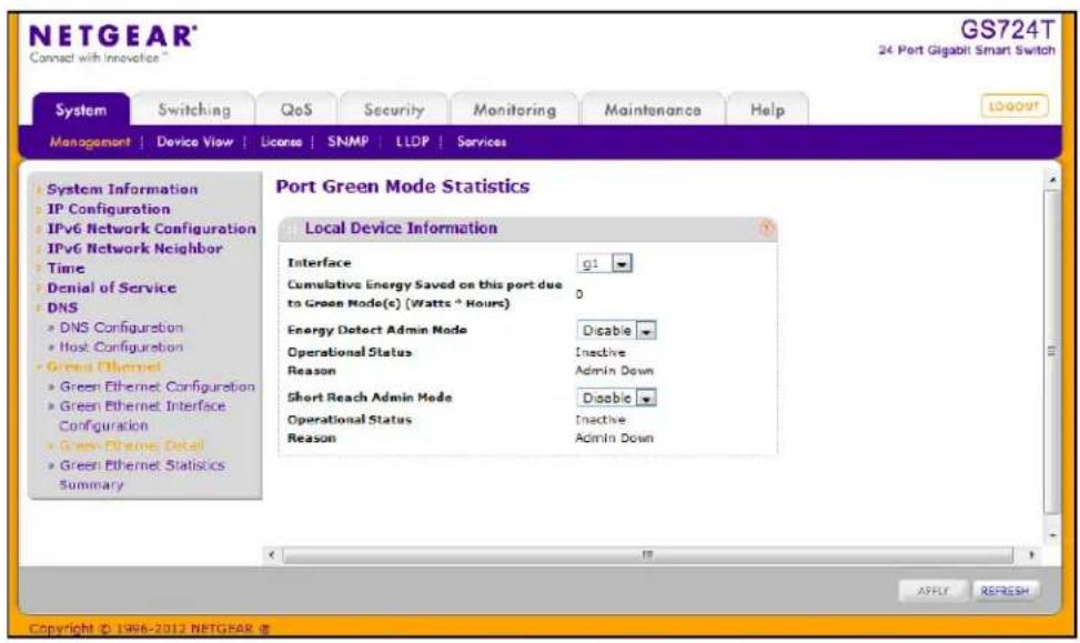
To configure or view details about the Green Ethernet feature on a port:
- Within the Local Device Information, select the port to view or configure from the Interface menu.
- Enable or disable the Energy Detect or Short Reach administrative modes on the interface.
- If you make any changes to the Green Ethernet modes for the port, click Apply.
- View the additional Green Ethernet information that displays for the port:
| Field Description | |
| Cumulative Energy Saved on this port due to Green Mode(s) (Watts * Hours) | Shows the energy savings per port, per hour. |
| Operational Status (Energy Detect) | Shows the Green Mode operational status, either Inactive or Active. |
| Reason Shows the Admin status, either Admin Down or Admin Up. | |
| Operational Status (Short Reach) | Shows the operational status of the port, either Active or Inactive. |
| Reason Shows the reason why the port is either Active or Inactive. | |
- Click Clear to reset the counters on the page to their default values.
- Click Refresh to update the page with the current information.
Green Ethernet Statistics Summary
This page summarizes the Green Ethernet Summary settings currently in use.
To access this page, click System > Management > Green Ethernet > Green Ethernet Statistics Summary.

The following table describes the information available on the Green Mode Statistics Summary page.
| Field Description | |
| Current Power Consumption by all ports in Stack (mWatts) | Estimated Power Consumption by all ports in the stack in mWatts. |
| Estimated Percentage Power Saving per stack (%) | Estimated Percentage Power saved on all ports in the stack due to Green mode(s) enabled. |
| Cumulative Energy Saving per Stack (Watts*Hours) | Estimated Cumulative Energy saved per stack in (Watts × Hours) due to all green modes enabled. |
| Unit Identifies the stack member number. | |
| Green Features supported on this unit | List of Green Features supported on the given unit which could be one or more of the following:Energy-Detect (Energy Detect)Short-Reach (Short Reach)Pwr-Usg-Est (Power Usage Estimates). |
| Interface Identifies the interface associated with the rest of the data in the row. | |
| Energy Detect Admin Mode | Shows whether Energy Detect Mode is administratively enabled on the port. |
| Energy Detect Operational Status | Shows the current operational status of the Green Mode for the selected port. |
| Short Reach Admin Mode | Shows the administrative status of Short Reach Mode on the port. With short reach mode enabled, PHY goes into low power mode when cable length is less than a given limit. |
| Short Reach Operational Status | Indicates whether the port is in low-power mode due to the cable length. |
Click Refresh to update the page with the most current data from the switch
License
From the License link under the System tab, you can view information about the switch license. The License link provides access to the following pages:
• Show License on page 56
• License Features on page 57
Show License
Use the Show License page to view information about the license key on the device. Some features might require a special license in order to be active. If a license is not active, the feature associated with the license is not available and cannot be configured.
To display the License Key page, click System > License > Show License. A screen similar to the following displays.
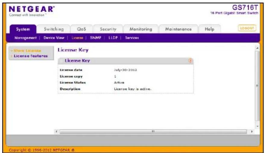
The following table describes the non-configurable fields on the License Key page.
| Field Description | |
| License Date The date the | license is purchased. |
| License Copy The number | of licenses that exist on the switch. |
| License Status Indicates | whether the license is active or inactive. If a license is inactive, a license should be purchased and downloaded to the switch. The license is not activated until the switch reboots. |
| Description A description of | the license key status. If the license is inactive, this field provides information about why it is inactive. |
License Features
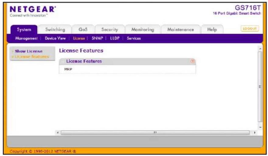
Use the License Features page to view information about the features on the device that require an active license.
To display the License Features page, click System > License > License Features. A screen similar to the following displays.
SNMP
From SNMP link under the System tab, you can configure SNMP settings for SNMP V1/V2 and SNMPv3.
From the SNMP link, you can access the following pages:
• SNMPV1/V2 on page 58
- Trap Flags on page 61
• SNMP v3 User Configuration on page 62
SNMPV1/V2
The pages under the SNMPV1/V2 menu allow you to configure SNMP community information, traps, and trap flags.
Community Configuration
To display this page, click System > SNMP > SNMP V1/V2 > Community Configuration.
By default, two SNMP Communities exist:
- Private, with Read/Write privileges and status set to Enable.
- Public, with Read Only privileges and status set to Enable.
These are well-known communities. Use this page to change the defaults or to add other communities. Only the communities that you define using this page will have access to the switch using the SNMPv1 and SNMPv2c protocols. Only those communities with read/write level access can be used to change the configuration using SNMP.
Use this page when you are using the SNMPv1 and SNMPv2c protocol.
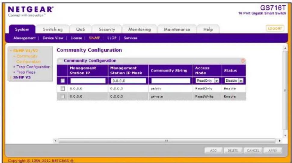
To configure SNMP communities:
-
To add a new SNMP community, enter community information in the available fields described below, and then click Add.
-
Management Station IP. Specify the IP address of the management station. Together, the Management Station IP and the Management Station IP Mask denote a range of IP addresses from which SNMP clients may use that community to access this device. If either (Management Station IP or Management Station IP Mask) value is 0.0.0.0, access is allowed from any IP address. Otherwise, every client's address is ANDed with the mask, as is the Management Station IP Address; and, if the values are equal, access is allowed. For example, if the Management Station IP and Management Station IP Mask parameters are 192.168.1.0/255.255.255.0, then any client whose address is 192.168.1.0 through 192.168.1.255 (inclusive) will be allowed access. To allow access from only one station, use a Management Station IP Mask value of 255.255.255.255, and use that machine's IP address for Client Address.
- Management Station IP Mask. Specify the subnet mask to associate with the management station IP address.
- Community String. Specify a community name. A valid entry is a case-sensitive string of up to 16 characters.
- Access Mode. Specify the access level for this community by selecting Read/Write or Read Only from the menu.
-
Status. Specify the status of this community by selecting Enable or Disable from the pull down menu. If you select Enable, the Community Name must be unique among all valid Community Names or the set request will be rejected. If you select Disable, the Community Name will become invalid.
-
To modify an existing community, select the check box next to the community, change the desired fields, and then click Apply. Configuration changes take effect immediately.
-
To delete a community, select the check box next to the community and click Delete.
-
Click Cancel to cancel the configuration on the screen and reset the data on the screen to the latest value of the switch.
Trap Configuration
This page displays an entry for every active Trap Receiver. To access this page, click System > SNMP > SNMP V1/V2 > Trap Configuration.
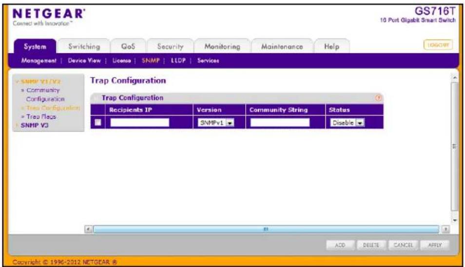
To configure SNMP trap settings:
- To add a host that will receive SNMP traps, enter trap configuration information in the available fields described below, and then click Add.
• Recipients IP. The address in x.x.x.x format to receive SNMP traps from this device.
- Version. The trap version to be used by the receiver from the menu.
- SNMP v1: Uses SNMP v1 to send traps to the receiver.
- SNMP v2: Uses SNMP v2 to send traps to the receiver.
- Community String. The community string for the SNMP trap packet to be sent to the trap manager. This may be up to 16 characters and is case sensitive.
- Status. Select the receiver's status from the menu:
- Enable: Send traps to the receiver.
- Disable: Do not send traps to the receiver.
- To modify information about an existing SNMP recipient, select the check box next to the recipient, change the desired fields, and then click Apply. Configuration changes take effect immediately.
- To delete a recipient, select the check box next to the recipient and click Delete.
- Click Cancel to cancel the configuration on the screen and reset the data on the screen to the latest value of the switch.
Trap Flags
The pages in the Trap Manager folder allow you to view and configure information about SNMP traps the system generates.
Use the Trap Flags page to enable or disable traps the switch can send to an SNMP manager. When the condition identified by an active trap is encountered by the switch, a trap message is sent to any enabled SNMP Trap Receivers, and a message is written to the trap log.
To access the Trap Flags page, click System > SNMP > SNMP V1/V2 > Trap Flags.
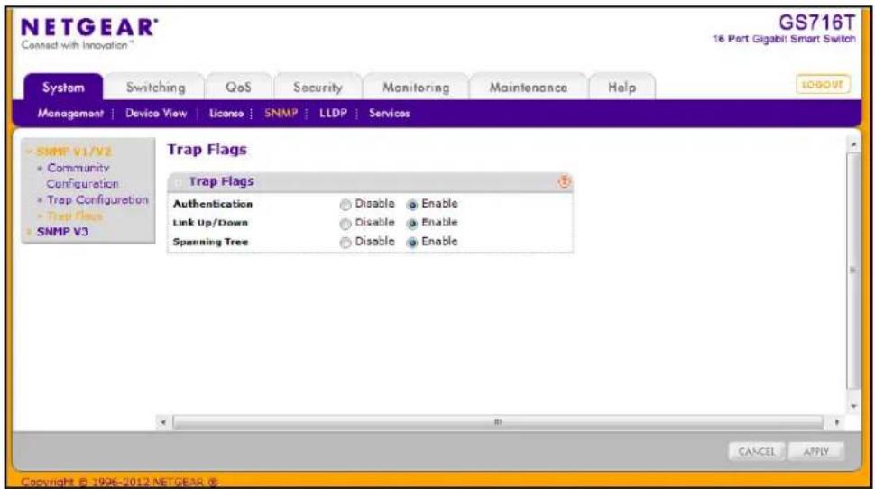
To configure the trap flags:
- From the Authentication field, enable or disable activation of authentication failure traps by selecting the corresponding button. The factory default is Enable.
- From the Link Up/Down field, enable or disable activation of link status traps by selecting the corresponding button. The factory default is Enable.
- From the Spanning Tree field, enable or disable activation of spanning tree traps by selecting the corresponding button. The factory default is Enable.
- If you make any changes to this page, click Apply to send the updated configuration to the switch. Configuration changes take effect immediately.
- Click Cancel to cancel the configuration on the screen and reset the data on the screen to the latest value of the switch.
SNMP v3 User Configuration
Use this page to configure user access for management of the switch using SNMP v3.
To access this page, click System > SNMP > SNMP V3 > User Configuration.
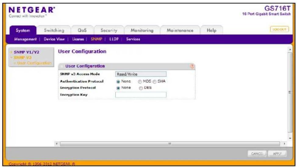
The SNMPv3 Access Mode is a read-only field that shows the access privileges for the user account. The admin account always has Read/Write access, and all other accounts have Read Only access.
To configure SNMPv3 settings for the user account:
- In the Authentication Protocol field, specify the SNMPv3 Authentication Protocol setting for the selected user account. The valid Authentication Protocols are None, MD5, or SHA. If you select:
• None: The user will be unable to access the SNMP data from an SNMP browser.
- MD5 or SHA: The user login password will be used as SNMPv3 authentication password, and you must therefore specify a password. The password must be eight characters in length.
- In the Encryption Protocol field, choose whether to encrypt SNMPv3 packets transmitted by the switch.
• None. Do not encrypt the contents of SNMPv3 packets transmitted from the switch.
• DES. Encrypt SNMPv3 packets using the DES encryption protocol.
- If you selected DES in the Encryption Protocol field, enter the SNMPv3 Encryption Key here. Otherwise, this field is ignored. Valid keys are 0 to 15 characters long.
- Click Apply to send the updated configuration to the switch. Configuration changes take effect immediately.
- Click Cancel to cancel the configuration on the screen and reset the data on the screen to the latest value of the switch.
LLDP
The IEEE 802.1AB-defined standard, Link Layer Discovery Protocol (LLDP), allows stations on an 802 LAN to advertise major capabilities and physical descriptions. This information is viewed by a network manager to identify system topology and detect bad configurations on the LAN.
From the LLDP link, you can access the following pages:
• LLDP Configuration on page 63
• LLDP Port Settings on page 65
• LLDP-MED Network Policy on page 66
• LLDP-MED Port Settings on page 67
- Local Information on page 68
- Neighbors Information on page 72
LLDP is a one-way protocol; there are no request/response sequences. Information is advertised by stations implementing the transmit function, and is received and processed by stations implementing the receive function. The transmit and receive functions can be enabled/disabled separately per port. By default, both transmit and receive are enabled on all ports. The application is responsible for starting each transmit and receive state machine appropriately, based on the configured status and operational state of the port.
The Link Layer Discovery Protocol-Media Endpoint Discovery (LLDP-MED) is an enhancement to LLDP with the following features:
- Auto-discovery of LAN policies (such as VLAN, Layer 2 Priority, and DiffServ settings), enabling plug and play networking.
• Device location discovery for creation of location databases. - Extended and automated power management of Power over Ethernet endpoints.
- Inventory management, enabling network administrators to track their network devices and determine their characteristics (manufacturer, software and hardware versions, serial/asset number).
LLDP Configuration
Use the LLDP Configuration page to specify LLDP and LLDP-MED parameters that are applied to the switch.
To display the LLDP Configuration page, click System > LLDP > Basic > LLDP Configuration.
Note: You can also access the LLDP Configuration page by clicking
System > LLDP > Advanced > LLDP Configuration.
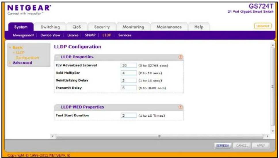
To configure global LLDP settings:
-
Configure the following LLDP properties.
-
TLV Advertised Interval. Specify the interval at which frames are transmitted. The default is 30 seconds, and the valid range is 5–32768 seconds.
- Hold Multiplier. Specify multiplier on the transmit interval to assign to Time-to-Live (TTL). The default is 4, and the range is 2–10.
- Reinitializing Delay. Specify the delay before a reinitialization. The default is 2 seconds, and the range is 1–10 seconds.
-
Transmit Delay. Specify the interval for the transmission of notifications. The default is 5 seconds, and the range is 5–3600 seconds.
-
To change the LLDP-MED properties in the Fast Start Duration field, specify the number of LLDP packets sent when the LLDP-MED Fast Start mechanism is initialized, which occurs when a new endpoint device links with the LLDP-MED network connectivity device. The default value is 3, and the range is from 1–10.
- Click Apply to apply the new settings to the system.
- Click Cancel to cancel the configuration on the screen and reset the data on the screen to the latest value of the switch.
- Click Refresh to update the screen with the current information.
LLDP Port Settings
Use the LLDP Port Settings page to specify LLDP parameters that are applied to a specific interface.
To display the LLDP Port Settings page, click System > LLDP > Advanced > LLDP Port Settings.
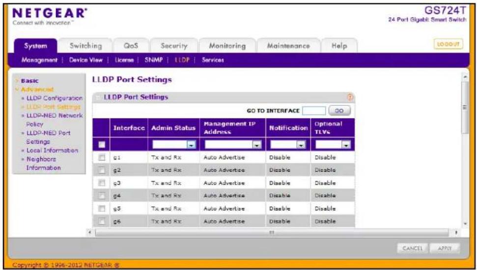
To configure LLDP port settings:
- Change the LLDP port settings described below:
• Interface. Specifies the port to be affected by these parameters.
- Admin Status. Select the status for transmitting and receiving LLDP packets:
- Tx Only: Enable only transmitting LLDP PDUs on the selected ports.
- Rx Only: Enable only receiving LLDP PDUs on the selected ports.
- Tx and Rx: Enable both transmitting and receiving LLDP PDUs on the selected ports. This is the default value.
- Disabled: Do not transmit or receive LLDP PDUs on the selected ports.
- Management IP Address. Choose whether to advertise the management IP address from the interface. The possible field values are:
- Stop Advertise: Do not advertise the management IP address from the interface.
• Auto Advertise: Advertise the current IP address of the device as the management IP address.
- Notification. When notifications are enabled, LLDP interacts with the Trap Manager to notify subscribers of remote data change statistics. The default is Disabled.
- Optional TLV(s). Enable or disable the transmission of optional type-length value (TLV) information from the interface. The TLV information includes the system name, system description, system capabilities, and port description. The default is enabled. To configure the System Name, see Management on page 31. To configure the Port Description, see Ports on page 79.
-
If you make any changes to the page, click Apply to apply the new settings to the system.
-
Click Cancel to cancel the configuration on the screen and reset the data on the screen to the latest value of the switch.
LLDP-MED Network Policy
This page displays information about the LLPD-MED network policy TLV transmitted in the LLDP frames on the selected local interface.
To display this page, click System > LLDP > Advanced > LLDP-MED Network Policy.
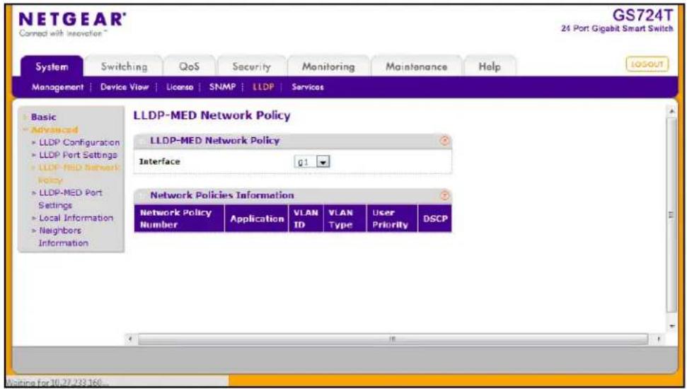
From the Interface menu, select the interface with the information to view. The following table describes the LLDP-MED network policy information that displays on the screen.
| Field Description | |
| Network Policy Number Specifies the policy number. | |
| Application Specifies the media | application type associated with the policy, which can only be Voice.The application information is displayed only if a network policy TLV has been transmitted from the port. |
| VLAN ID Specifies the VLAN ID | associated with the policy. |
| VLAN Type Specifies whether | the VLAN associated with the policy is tagged or untagged. |
| User Priority Specifies the priority | associated with the policy. |
| DSCP | Specifies the DSCP associated with a particular policy type. |
Click Refresh to refresh the page with the most current data from the switch.
LLDP-MED Port Settings
Use this page to enable LLDP-MED mode on an interface and configure its properties.
To display this page, click System > LLDP > Advanced > LLDP-MED Port Settings.
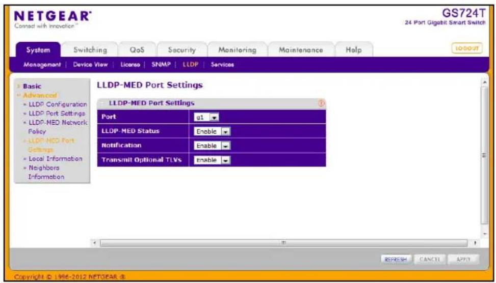
To configure LLDP-MED settings for a port:
- From the Port field, select the port to configure.
- From the LLDP-MED Status field, enable or disable the LLDP-MED mode for the selected interface.
-
From the Notification field, specify whether the port should send a topology change notification if a device is connected or removed.
-
From the Transmit Optional TLVs field, specify whether the port should transmit optional type length values (TLVs) in the LLDP PDU frames. If enabled, the following LLDP-MED TLVs are transmitted:
• MED Capabilities
• Network Policy
- Location Identification
• Extended Power via MDI: PSE
• Extended Power via MDI: PD
- Inventory
-
Click Apply to send the updated configuration to the switch. These changes occur immediately and the configuration will be saved.
-
Click Cancel to cancel the configuration on the screen and reset the data on the screen to the latest value of the switch.
Local Information
Use the LLDP Local Information page to view the data that each port advertises through LLDP.
To display the LLDP Local Device Information page, click System > Advanced > LLDP > Local Information.
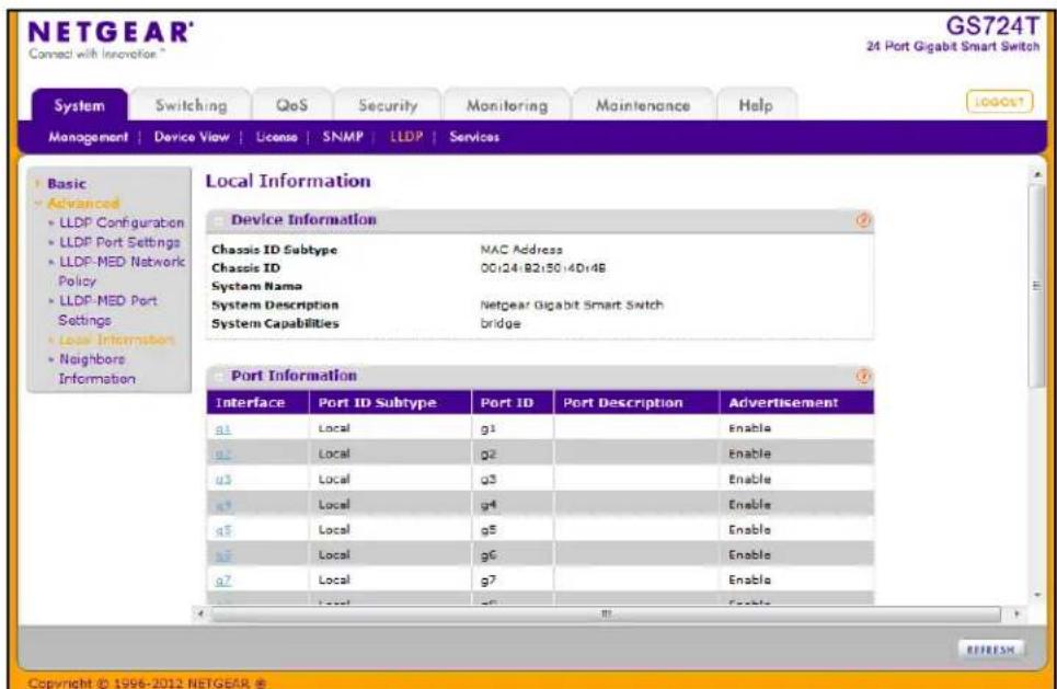
If LLDP or LLDP-MED is enabled on one or more ports, the Device Information table displays information about the device that is transmitted in TLVs, as the following table describes:
| Field Description | |
| Chassis ID Subtype The type | of information used to identify the GS716T and GS724T in the Chassis ID field. |
| Chassis ID The hardware platform identifier for the GS716T and GS724T. | |
| System Name The user-configured system name for the GS716T and GS724T. | |
| System Description The device description, which includes information about the product model and platform. | |
| System Capabilities The primary function(s) the GS716T and GS724T supports. | |
The Port Information table provides information about the LLDP and LLDP-MED status of each port, as the following table describes:
| Field Description | |
| Interface Select the interface | with the information to display. |
| Port ID Subtype Identifies the type of data displayed in the Port ID field. | |
| Port ID Identifies the physical address of the port. | |
| Port Description Identifies the user-defined description of the port. To configure the Port Description, see Ports on page 79. | |
| Advertisement Displays the advertisement status of the port. | |
Click Refresh to refresh the page with the most current data from the switch.
To view additional details about a port, click the name of the port in the Interface column of the Port Information table.
A popup window displays information for the selected port.
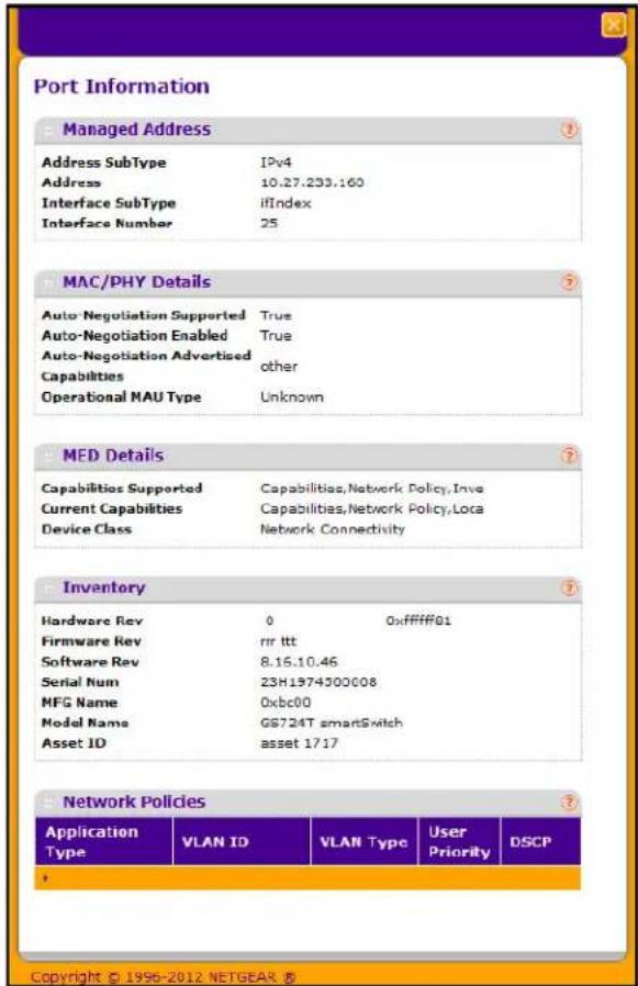
The following table describes the detailed local information that displays for the selected port.
| Field Description | |
| Managed Address | |
| Address SubType | Displays the type of address the management interface uses, such as an IPv4 address. |
| Address Displays the address used to manage the device. | |
| Interface SubType Displays the port subtype. | |
| Interface Number Displays the number that identifies the port. | |
| MAC/PHY Details | |
| Auto-Negotiation Supported | Specifies whether the interface supports port-speed auto-negotiation. The possible values are True or False. |
| Auto-Negotiation Enabled | Displays the port speed auto-negotiation support status. The possible values are True (enabled) or False (disabled). |
| Auto Negotiation Advertised Capabilities | Displays the port speed auto-negotiation capabilities such as 1000BASE-T half-duplex mode or 100BASE-TX full-duplex mode. |
| Operational MAU Type Displays | ays the Medium Attachment Unit (MAU) type. The MAU performs physical layer functions, including digital data conversion from the Ethernet interface collision detection and bit injection into the network. |
| MED Details | |
| Capabilities Supported Displays | the MED capabilities enabled on the port. |
| Current Capabilities Displays | the TLVs advertised by the port. |
| Device Class Network Connectivity | activity indicates the device is a network connectivity device. |
| Network Policies | |
| Application Type Specifies the media application type associated with the policy. | |
| VLAN ID Specifies the VLAN | ID associated with the policy. |
| VLAN Type Specifies whether the VLAN associated with the policy is tagged or untagged. | |
| User Priority Specifies the priority associated with the policy. | |
| DSCP Specifies the DSCP associated with a particular policy type. | |
Neighbors Information
Use the LLDP Neighbors Information page to view the data that a specified interface has received from other LLDP-enabled systems.
To display the LLDP Neighbors Information page, click System > LLDP > Advanced > Neighbors Information.
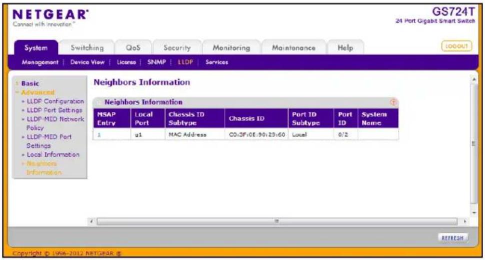
The following table describes the information that displays for all LLDP neighbors that have been discovered.
| Field Description | |
| MSAP Entry Displays the Media Service Access Point (MSAP) entry number for the remote device. | |
| Local Port Displays the interface on the local system that received LLDP information from a remote system. | |
| Chassis ID Subtype Identifies the type of data displayed in the Chassis ID field on the remote system. | |
| Chassis ID Identifies the remote 802 LAN device's chassis. | |
| Port ID Subtype Identifies the type of data displayed in the remote system's Port ID field. | |
| Port ID Identifies the physical address of the port on the remote system from which the data was sent. | |
| System Name Identifies the system name associated with the remote device. If the field is blank, the name might not be configured on the remote system. | |
Click Refresh to update the information on the screen with the most current data.
To view additional information about the remote device, click the link in the MSAP Entry field.
A popup window displays information for the selected port.
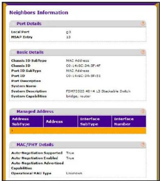
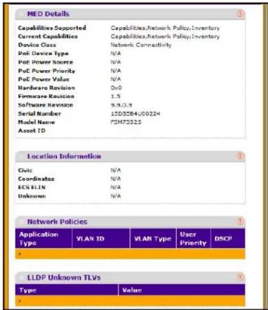
| Field Description | |
| Port Details | |
| Local Port Displays the interface on the local system that received LLDP information from a remote system. | |
| MSAP Entry Displays the Media Service Access Point (MSAP) entry number for the remote device. | |
| Basic Details | |
| Chassis ID Subtype Identifies the type of data displayed in the Chassis ID field on the remote system. | |
| Chassis ID Identifies the remote 802 LAN device's chassis. | |
| Port ID Subtype Identifies the type of data displayed in the remote system's Port ID field. | |
| Port ID Identifies the physical address of the port on the remote system from which the data was sent. | |
| Port Description Identifies the user-defined description of the port. | |
| System Name Identifies the system name associated with the remote device. | |
| System Description Specifies the description of the selected port associated with the remote system. | |
| System Capabilities Specifies the system capabilities of the remote system. | |
| Field | Description |
| Managed Addresses | |
| Address SubType Specifies the type of the management address. | |
| Address Specifies the advertised management address of the remote system. | |
| Interface SubType Specifies the port subtype. | |
| Interface Number Identifies the port on the remote device that sent the information. | |
| MAC/PHY Details | |
| Auto-Negotiation Supported $ specifies whether the remote device supports port-speed auto-negotiation. The possible values are True or False | |
| Auto-Negotiation Enabled | Displays the port speed auto-negotiation support status. The possible values are True or False |
| Auto Negotiation Advertised Capabilities | Displays the port speed auto-negotiation capabilities. |
| Operational MAU Type Displays the Medium Attachment Unit (MAU) type. The MAU performs physical layer functions, including digital data conversion from the Ethernet interface collision detection and bit injection into the network. | |
| MED Details | |
| Capabilities Supported | Specifies the supported capabilities that were received in MED TLV from the device. |
| Current Capabilities | Specifies the advertised capabilities that were received in MED TLV from the device. |
| Device Class Displays the LLDP-MED endpoint device class. The possible device classes are: · Endpoint Class 1 Indicates a generic endpoint class, offering basic LLDP services. · Endpoint Class 2 Indicates a media endpoint class, offering media streaming capabilities as well as all Class 1 features. · Endpoint Class 3 Indicates a communications device class, offering all Class 1 and Class 2 features plus location, 911, Layer 2 switch support and device information management capabilities. | |
| Hardware Revision Displays the hardware version advertised by the remote device. | |
| Firmware Revision Displays the firmware version advertised by the remote device. | |
| Software Revision Displays the software version advertised by the remote device. | |
| Serial Number Displays the serial number advertised by the remote device. | |
| Model Name Displays the model name advertised by the remote device. | |
| Asset ID | Displays the asset ID advertised by the remote device. |
| Field Description | |
| Location Information | |
| Civic Displays the physical location | location, such as the street address, the remote device has advertised in the location TLV. For example, 123 45th St. E. The field value length range is 6–160 characters. |
| Coordinates Displays the location map | location maps coordinates the remote device has advertised in the location TLV, including latitude, longitude and altitude. |
| ECS ELIN Displays the Emergency Location | Identification Number (ELIN) the remote device has advertised in the location TLV. The field range is 10–25. |
| Unknown Displays unknown location information for the remote device. | |
| Network Policies | |
| Application Type Specifies the media application type associated with the policy advertised by the remote device. | |
| VLAN ID Specifies the VLAN ID associated with the policy. | |
| VLAN Type Specifies whether the VLAN associated with the policy is tagged or untagged. | |
| User Priority Specifies the priority associated with the policy. | |
| DSCP Specifies the DSCP associated with a particular policy type. | |
| LLDP Unknown TLVs | |
| Type Displays the unknown TLV type field. | |
| Value Displays the unknown TLV value field. | |
Services — DHCP Filtering
DHCP Filtering is a useful feature that can be employed as a security measure against unauthorized DHCP servers. A known attack is when an unauthorized DHCP server responds to a client that is requesting an IP address. The server configures the gateway for the client to be equal to the IP address of the server. At that point, the client sends all of its IP traffic destined to other networks to the unauthorized machine. This gives the attacker the possibility of snooping traffic for passwords or employing a man-in-the-middle attack. DHCP Filtering works by allowing the administrator to configure each port as either a trusted port or an untrusted port. The port that has the authorized DHCP server should be configured as a trusted port. Any DHCP responses received on a trusted port are forwarded. All other ports should be configured as untrusted. Any DHCP (or BootP) responses received are discarded.
From the Services link, you can access the following pages:
• DHCP Filtering Configuration on page 76
• Interface Configuration on page 77
DHCP Filtering Configuration
Use the DHCP Filtering Configuration page to enable or disable the DHCP Filtering feature on the switch.
To access the DHCP Filter Configuration page, click System > Services > DHCP Filtering > Configuration.
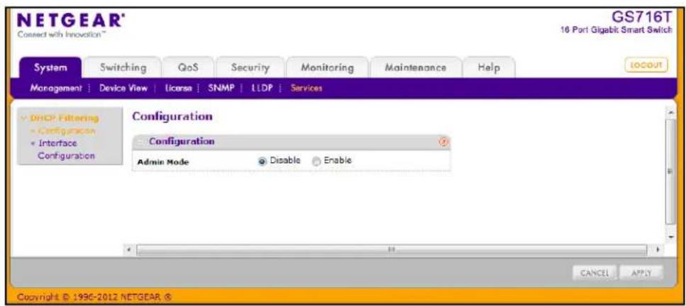
To configure global DHCP filtering settings:
- In the Admin Mode field, select Enable or Disable to turn the DHCP Filtering feature or off
- Click Apply to apply the change to the system. Configuration changes take effect immediately.
- Click Cancel to cancel the configuration on the screen and reset the data on the screen to the latest value of the switch.
Interface Configuration
Use the DHCP Filtering Interface Configuration page to view and configure each port as a trusted or untrusted port. Any DHCP responses received on a trusted port are forwarded. If a port is configured as untrusted, any DHCP (or BootP) responses received on that port are discarded.
To access the DHCP Filtering Interface Configuration page, click System > Services > DHCP Filtering > Interface Configuration.
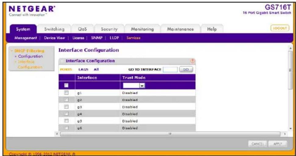
To configure DHCP filtering settings for an interface:
-
To configure DHCP filtering settings for a physical port, click PORTS.
-
To configure DHCP filtering settings for a Link Aggregation Group (LAG), click LAGS.
-
To configure DHCP filtering settings for both physical ports and LAGs, click ALL.
-
Select the check box next to the port or LAG to configure. You can select multiple ports and LAGs to apply the same setting to the selected interfaces. Select the check box in the heading row to apply the same settings to all interfaces.
-
Choose the trust mode for the selected port(s) or LAG(s).
-
Enable: Any DHCP responses received on this port are forwarded. The port connected downstream from the authorized DHCP server should be configured as a trusted port. Any DHCP responses received on a trusted port are forwarded. All other ports should be configured as untrusted. Any DHCP (or BootP) responses received are discarded.
-
Disable: Any DHCP (or BootP) responses received on this port are discarded. Ports connected to hosts should be configured as untrusted. This is the default value.
-
Click Apply to apply the change to the system. Configuration changes take effect immediately.
-
Click Cancel to cancel the configuration on the screen and reset the data on the screen to the latest value of the switch.
GS716T and GS724T Gigabit Smart Switches
Use the features in the Switching tab to define Layer 2 features. The Switching tab contains links to the following features:
- Ports on page 79
- Link Aggregation Groups on page 83
• VLANs on page 89
• Voice VLAN on page 94
• Auto-VoIP Configuration on page 98
• Spanning Tree Protocol on page 99
• Multicast on page 112 - Address Table on page 128
• 802.1AS on page 145
• Multiple Registration Protocol Configuration on page 132
Ports
The pages on the Ports tab allow you to view and monitor the physical port information for the ports available on the switch. From the Ports link, you can access the following pages:
• Port Configuration on page 80
• Flow Control on page 82
Port Configuration
Use the Port Configuration page to configure the physical interfaces on the switch.
To access the Port Configuration page, click Switching > Ports > Port Configuration.
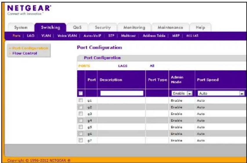
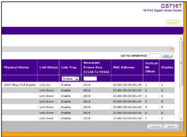
To configure port settings:
- To configure settings for a physical port, click PORTS.
- To configure settings for a Link Aggregation Group (LAG), click LAGS.
-
To configure settings for both physical ports and LAGs, click ALL.
-
Select the check box next to the port or LAG to configure. You can select multiple ports and LAGs to apply the same setting to the selected interfaces. Select the check box in the heading row to apply the same settings to all interfaces.
-
Configure or view the settings:
-
Description. Enter the description string to be attached to a port. The string can be up to 64 characters in length.
- Port Type. For most ports this field is blank. Otherwise, the possible values are:
- Probe: Indicates that the port is a monitoring (destination) port. For additional information about port monitoring see Port Mirroring on page 250.
- Mirrored: The port is a source port and mirrors traffic to the probe port. For additional information about port monitoring see Port Mirroring on page 250.
- LAG: Indicates that the port is a member of a Link Aggregation trunk. For more information see Link Aggregation Groups on page 83.
- Admin Mode. Use the menu to select the port control administration state, which can be one of the following:
- Enable: The port can participate in the network (default).
- Disable: The port is administratively down and does not participate in the network.
- Port Speed. Use the menu to select the port's speed and duplex mode. If you select Auto, the duplex mode and speed will be set by the auto-negotiation process. The port's maximum capability (full duplex and 1000 Mbps) will be advertised. Otherwise, your selection will determine the port's duplex mode and transmission rate. The factory default is Auto.
- Physical Status. Indicates the physical port's speed and duplex mode
- Link Status. Indicates whether the Link is up or down.
- Link Trap. This object determines whether or not to send a trap when link status changes. The factory default is Enable.
- Enable: Specifies that the system sends a trap when the link status changes.
- Disable: Specifies that the system does not send a trap when the link status changes.
- Maximum Frame Size. Specifies the maximum Ethernet frame size the interface supports. The size includes the Ethernet header, CRC, and payload. Any change to the maximum frame size is immediately applied to all interfaces.
• MAC Address. Displays the physical address of the specified interface. - PortList Bit Offset. Displays the bit offset value which corresponds to the port when the MIB object type PortList is used to manage in SNMP.
-
ifIndex. The ifIndex of the interface table entry associated with this port. If the interface field is set to All, this field is blank.
-
Click Cancel to cancel the configuration on the screen and reset the data on the screen to the latest value of the switch.
-
If you make any changes to the page, click Apply to apply the changes to the system.
Flow Control
IEEE 802.3x flow control works by pausing a port when the port becomes oversubscribed and dropping all traffic for small bursts of time during the congestion condition. This can lead to high-priority and/or network control traffic loss. When IEEE 802.3x flow control is enabled, lower speed switches can communicate with higher speed switches by requesting that the higher speed switch refrains from sending packets. Transmissions are temporarily halted to prevent buffer overflows.
To display the Flow Control page, click Switching >Ports, and then click the Flow Control link.
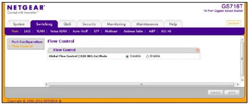
To configure global flow control settings:
-
From the Global Flow Control (IEEE 802.3x) Mode field, enable or disable IEEE 802.3x flow control on the system. The factory default is Disable.
-
Enable. The switch sends pause packets if the port buffers become full.
-
Disable. The switch does not send pause packets if the port buffers become full.
-
Click Cancel to cancel the configuration on the screen and reset the data on the screen to the latest value of the switch.
-
If you change the mode, click Apply to apply the changes to the system.
The GS716T and GS724T supports two combo ports using 1000M SFP modules. Each combo port can operate in either 'copper' or 'fiber' mode. When a cable is plugged into the RJ-45 port, copper mode is used. When a SFP module is plugged in, fiber mode is used.
The system automatically detects the media that is in use on a combo port and operates accordingly. The SFP transceiver takes precedence over the RJ-45 copper port.
In particular, the following behavior of combo port mechanism is followed:
- When SFP transceiver is present in (plugged into) the SFP slot and optical link is established via the SFP transceiver the combo port mechanism will use the SFP transceiver and shut down the RJ-45 copper port regardless of the state of the latter (that is, regardless of the copper port link being up or down);
- If (and while) the optical link is down (SFP transceiver is not present in the SFP slot or fiber cable is unplugged from SFP transceiver or optical link is shut down on the other side of the fiber cable, etc.), then the combo port mechanism will use the RJ-45 copper port.
It is possible to switch between the RJ-45 copper port and the SFP transceiver without a system reboot or reset.
Link Aggregation Groups
Link aggregation groups (LAGs), which are also known as port-channels, allow you to combine multiple full-duplex Ethernet links into a single logical link. Network devices treat the aggregation as if it were a single link, which increases fault tolerance and provides load sharing. You assign the LAG VLAN membership after you create a LAG. The LAG by default becomes a member of the management VLAN.
A LAG interface can be either static or dynamic, but not both. All members of a LAG must participate in the same protocols. A static port-channel interface does not require a partner system to be able to aggregate its member ports.
Static LAGs are supported. When a port is added to a LAG as a static member, it neither transmits nor receives LAGPDUs. The GS716T and GS724T Smart Switches supports eight LAGs.
From the LAGs link, you can access the following pages:
• LAG Configuration on page 84
• LAG Membership on page 85
• LACP Configuration on page 87
• LACP Port Configuration on page 88
LAG Configuration
Use the LAG (Port Channel) Configuration page to group one or more full-duplex Ethernet links to be aggregated together to form a link aggregation group, which is also known as a port-channel. The switch treats the LAG as if it were a single link.
To access the LAG Configuration page, click Switching > LAG > Basic > LAG Configuration.
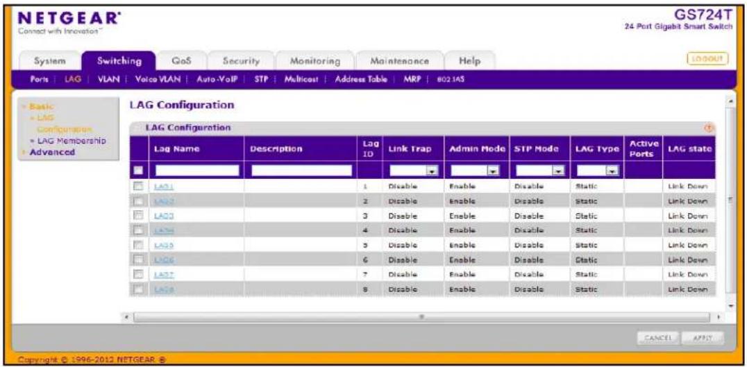
To configure LAG settings:
-
Select the check box next to the LAG to configure. You can select multiple LAGs to apply the same setting to the selected interfaces. Select the check box in the heading row to apply the same settings to all interfaces.
-
Configure or view the following settings:
-
LAG Name. Specify the name you want assigned to the LAG. You may enter any string of up to 15 alphanumeric characters. A valid name has to be specified in order to create the LAG
- Description. Specify the Description string to be attached to a LAG. It can be up to 64 characters in length.
- LAG ID. Displays the number assigned to the LAG. This field is read-only.
- Link Trap. Specify whether you want to have a trap sent when link status changes. The factory default is Disable, which will cause the trap to be sent.
- Admin Mode. Select Enable or Disable from the menu. When the LAG (port channel) is disabled, no traffic will flow and LAGPDUs will be dropped, but the links that form the LAG (port channel) will not be released. The factory default is Enable.
-
STP Mode. Select the Spanning Tree Protocol Administrative Mode associated with the LAG.
-
LAG Type. Specifies whether the LAG is configured as a Static or LACP port. When the LAG is static, it does not transmit or process received LAGPDUs, for example the member ports do not transmit LAGPDUs and all the LAGPDUs it may receive are dropped. The default is Static.
• Active Ports. A listing of the ports that are actively participating members of this Port Channel. A maximum of 8 ports can be assigned to a port channel. -
LAG State. Indicates whether the link is Up or Down.
-
Click Cancel to cancel the configuration on the screen and reset the data on the screen to the latest value of the switch.
-
If you make any changes to this page, click Apply to send the updated configuration to the switch. Configuration changes take effect immediately.
LAG Membership
Use the LAG Membership page to select two or more full-duplex Ethernet links to be aggregated together to form a link aggregation group (LAG), which is also known as a port-channel. The switch can treat the port-channel as if it were a single link.
To access the LAG Membership page, click Switching > LAG > Basic > LAG Membership.
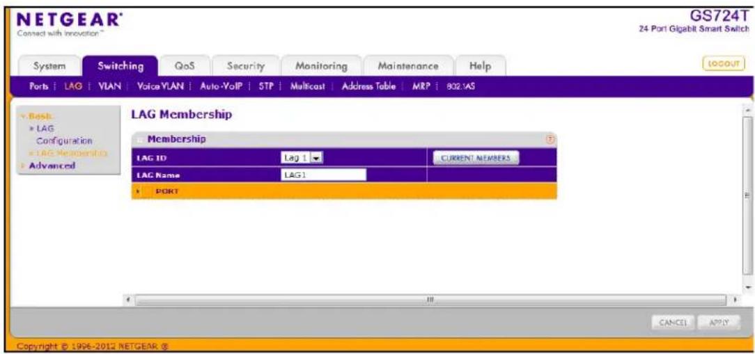
To add ports to a LAG:
- From the LAG ID field, select the LAG to configure.
- Optionally, in the LAG Name field, enter the name you want assigned to the LAG. You may enter any string of up to 15 alphanumeric characters. A valid name has to be specified to create the LAG.
- Click the orange bar to display the ports.
- Click the box below each port to include in the LAG. The following figure shows an example of how to configure LAG1 with ports g1–g4 as members.
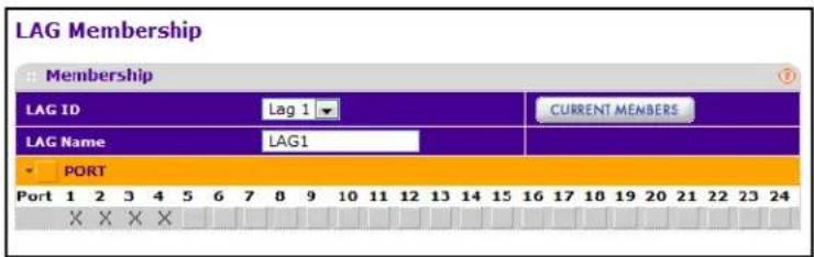
- Click Cancel to cancel the configuration on the screen and reset the data on the screen to the latest value of the switch.
- If you make any changes to this page, click Apply to send the updated configuration to the switch. Configuration changes take effect immediately.
- To view the ports that are members of the selected LAG, click Current Members.
LACP Configuration
To display the LACP Configuration page, click Switching > LAG > Advanced > LACP Configuration.
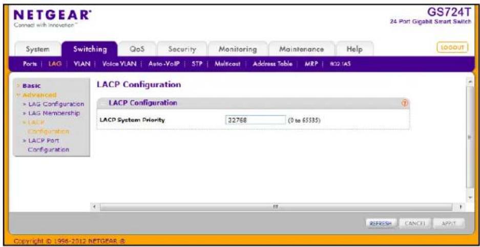
To configure LACP:
- From the LACP System Priority field, specify the device's link aggregation priority relative to the devices at the other ends of the links on which link aggregation is enabled. A higher value indicates a lower priority. You can change the value of the parameter globally by specifying a priority from 0–65535. The default value is 32768.
- Click Refresh to reload the page and display the most current information.
- Click Cancel to cancel the configuration on the screen and reset the data on the screen to the latest value of the switch.
- If you make any changes to this page, click Apply to send the updated configuration to the switch. Configuration changes take effect immediately.
LACP Port Configuration
To display the LACP Port Configuration page, click Switching > LAG > Advanced > LACP Port Configuration.
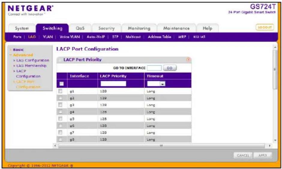
To configure LACP port priority settings:
- Select the check box next to the port to configure. You can select multiple ports to apply the same setting to all selected ports.
Note: You cannot select ports that are not participating in a LAG
- Configure the LACP Priority value for the selected port. The field range is 0–255. The default value is 128.
- Configure the administrative LACP Timeout value.
- Long. Specifies a long timeout value.
- Short. Specifies a short timeout value.
- Click Cancel to cancel the configuration on the screen and reset the data on the screen to the latest value of the switch.
- If you make any changes to this page, click Apply to send the updated configuration to the switch. Configuration changes take effect immediately.
VLANs
Adding Virtual LAN (VLAN) support to a Layer 2 switch offers some of the benefits of both bridging and routing. Like a bridge, a VLAN switch forwards traffic based on the Layer 2 header, which is fast, and like a router, it partitions the network into logical segments, which provides better administration, security and management of multicast traffic.
By default, all ports on the switch are in the same broadcast domain. VLANs electronically separate ports on the same switch into separate broadcast domains so that broadcast packets are not sent to all the ports on a single switch. When you use a VLAN, users can be grouped by logical function instead of physical location.
Each VLAN in a network has an associated VLAN ID, which appears in the IEEE 802.1Q tag in the Layer 2 header of packets transmitted on a VLAN. An end station may omit the tag, or the VLAN portion of the tag, in which case the first switch port to receive the packet may either reject it or insert a tag using its default VLAN ID. A given port may handle traffic for more than one VLAN, but it can only support one default VLAN ID.
From the VLAN link, you can access the following pages:
• VLAN Configuration on page 89
• VLAN Membership Configuration on page 90
• Port VLAN ID Configuration on page 92
VLAN Configuration
Use the VLAN Configuration page to define VLAN groups stored in the VLAN membership table. The GS716T and GS724T supports up to 256 VLANs. VLAN 1 is created by default, and all ports are untagged members.
To display the VLAN Configuration page, lick Switching > VLAN > Basic > VLAN Configuration.
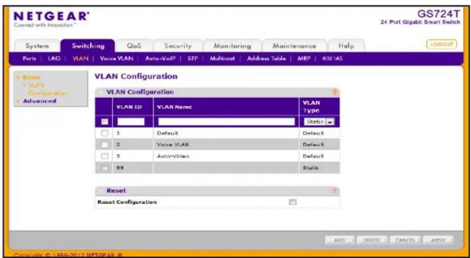
To configure VLANs:
-
To add a VLAN, configure the VLAN ID, name, and type, and then click Add.
-
VLAN ID. Specify the VLAN Identifier for the new VLAN. (You can enter data in this field only when you are creating a new VLAN.) The range of the VLAN ID is 1–4093.
- VLAN Name. Use this optional field to specify a name for a non-default VLAN. It can be up to 32 alphanumeric characters long, including blanks. The default is blank. VLANs 1–3 cannot be renamed.
-
VLAN Type. This field identifies the type of the VLAN you are configuring. The switch is preconfigured with three VLANS that have a VLAN Type of Default. VLAN 1 is the Default VLAN, VLAN 2 is the Voice VLAN, and VLAN 3 is the Auto-Video VLAN. These VLANs cannot be changed or deleted. When you create a VLAN on this page, its type will always be Static.
-
To delete a VLAN, select the check box next to the VLAN ID and click Delete. You cannot delete the default VLANs.
- To modify settings for a VLAN, select the check box next to the VLAN ID, change the desired information, and then click Apply. Configuration changes occur immediately.
- Click Cancel to cancel the configuration on the screen and reset the data on the screen to the latest value of the switch.
- To reset the VLAN settings on the switch to the factory defaults, select the Reset Configuration check box, and click OK in the popup message to confirm. If the Management VLAN is set to a non-default VLAN (VLAN 1), it is automatically set to 1 after a Reset Configuration.
VLAN Membership Configuration
Use this page to configure VLAN Port Membership for a particular VLAN. You can select the Group operation through this page.
To display the VLAN Membership Configuration page, click Switching > VLAN > Advanced > VLAN Membership.
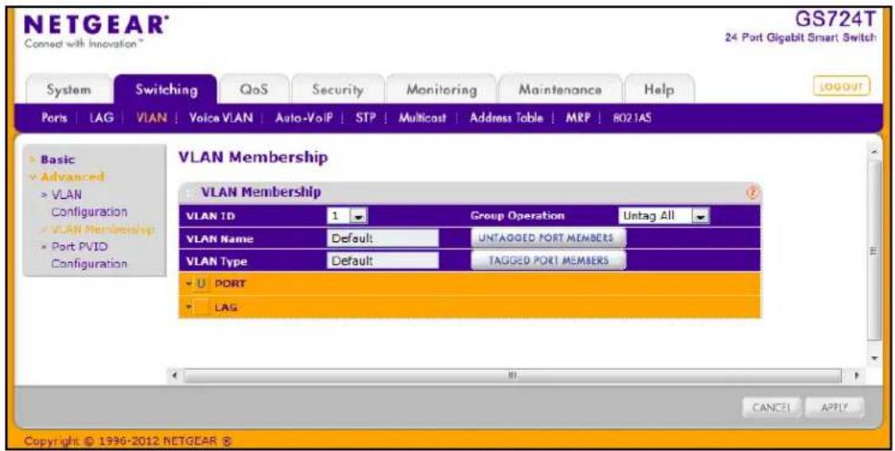
To configure VLAN membership:
- From the VLAN ID field, select the VLAN to which you want to add ports.
- Click the orange bar below the VLAN Type field to display the physical ports on the switch.
-
Click the lower orange bar to display the LAGs on the switch.
-
To select the port(s) or LAG(s) to add to the VLAN, click the square below each port or LAG. You can add each interface as a tagged (T) or untagged (U) VLAN member. A blank square means that the port is not a member of the VLAN.
-
Tagged: Frames transmitted from this port are tagged with the port VLAN ID.
- Untagged: Frames transmitted from this port are untagged. Each port can be an untagged member of only one VLAN. By default, all ports are an untagged member of VLAN 1.
In the following figure, ports g6, g7, g8, and LAG 1 are being added as tagged members to VLAN 99.
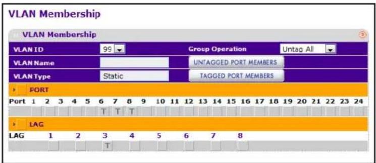
-
Use the Group Operations field to select all the ports and configure them. Possible values are:
-
Untag All: Select all the ports on which all frames transmitted from this VLAN will be untagged. All the ports will be included in the VLAN.
- Tag All: Select the ports on which all frames transmitted for this VLAN will be tagged. All the ports will be included in the VLAN.
-
Remove All: This selection has the effect of excluding all ports from the selected VLAN.
-
Click Cancel to cancel the configuration on the screen and reset the data on the screen to the latest value of the switch.
-
If you make any changes to this page, click Apply to send the updated configuration to the switch. Configuration changes take place immediately.
Port VLAN ID Configuration
The Port PVID Configuration screen lets you assign a port VLAN ID (PVID) to an interface. There are certain requirements for a PVID:
• All ports must have a defined PVID.
- If no other value is specified, the default VLAN PVID is used.
To access the Port PVID Configuration page, click Switching > VLAN > Advanced > Port PVID Configuration.
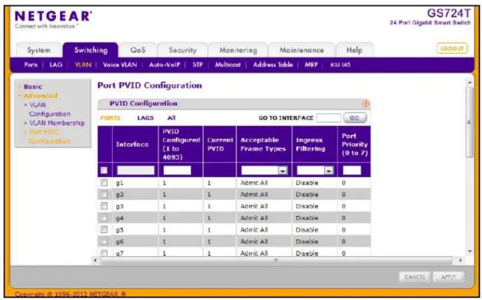
To configure PVID information:
- To configure PVID settings for a physical port, click PORTS.
- To configure PVID settings for a Link Aggregation Group (LAG), click LAGS.
- To configure PVID settings for both physical ports and LAGs, click ALL.
- Select the check box next to the interfaces to configure. You can select multiple interfaces to apply the same setting to the selected interfaces. Select the check box in the heading row to apply the same settings to all interfaces.
-
Configure the PVID to assign to untagged or priority tagged frames received on this port.
-
In the Acceptable Frame Type field, specify how you want the port to handle untagged and priority tagged frames. Whichever you select, VLAN tagged frames will be forwarded in accordance with the IEEE 802.1Q VLAN standard. The factory default is Admit All.
-
VLAN Only: The port will accept only VLAN-tagged frames and will discard any untagged or priority tagged frames it receives.
-
Admit All: Untagged and priority tagged frames received on the port will be accepted and assigned the value of the Port VLAN ID for this port.
-
In the Ingress Filtering field, specify how you want the port to handle tagged frames:
- Enable: A tagged frame will be discarded if this port is not a member of the VLAN identified by the VLAN ID in the tag. In an untagged frame, the VLAN is the Port VLAN ID specified for the port that received this frame.
- Disable: All frames are forwarded in accordance with the IEEE 802.1Q VLAN standard. The factory default is Disable.
- Specify the default 802.1p priority assigned to untagged packets arriving at the port. Possible values are 0–7.
- Click Cancel to cancel the configuration on the screen and reset the data on the screen to the latest value of the switch.
- If you make any changes to this page, click Apply to send the updated configuration to the switch. Configuration changes take place immediately.
Voice VLAN
Configure the Voice VLAN settings for ports that carry traffic from IP phones. The Voice VLAN feature can help ensure that the sound quality of an IP phone is safeguarded from deteriorating when the data traffic on the port is high.
From the VLAN link, you can access the following pages:
• Voice VLAN Properties on page 94
• Voice VLAN Port Setting on page 95
• Voice VLAN OUI on page 96
Voice VLAN Properties
To display the Voice VLAN Properties page, click Switching > Voice VLAN > Basic > Properties.
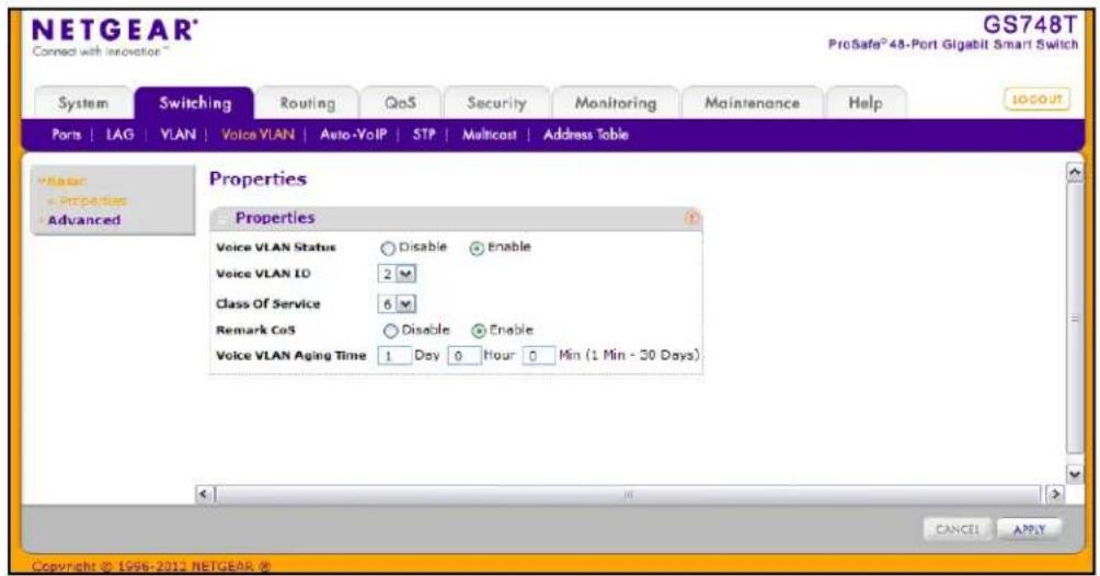
To configure Voice VLAN:
- From the Voice VLAN Status field, enable or disable Voice VLAN on the switch. If the switch does not handle traffic from IP phones, the status should be disabled.
- From the Voice VLAN ID field, select the VLAN to use for voice traffic on the switch. The VLAN must already exist on the switch. For information about how to create VLANs, see VLAN Configuration on page 89.
- From the Class of Service field, set the CoS tag value to be reassigned for packets received on the Voice VLAN when Remark CoS is enabled.
-
From the Remark CoS field, select Enable or Disable to reassign the CoS tag value to packets received on the Voice VLAN.
-
From the Voice VLAN Aging Time field, specify the amount of time after the last IP phone's OUI is aged out for a specific port. The port will age out after the bridge and voice aging time.
- Click Cancel to cancel the configuration on the screen and reset the data on the screen to the latest value of the switch.
- If you make any changes to this page, click Apply to send the updated configuration to the switch.
Voice VLAN Port Setting
To display the Voice VLAN Port Setting page, click Switching > Voice VLAN > Advanced > Port Setting.
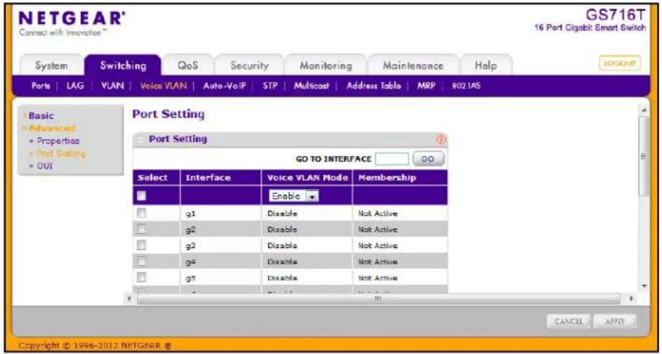
To configure Voice VLAN port settings:
- Select the check box next to the port to configure. You can select multiple check boxes to apply the same setting to all selected ports.
- From the Voice VLAN Mode menu, specify whether to enable or disable Voice VLAN on the selected port.
- Click Cancel to cancel the configuration on the screen and reset the data on the screen to the latest value of the switch.
- If you make any changes to this page, click Apply to send the updated configuration to the switch.
Note: The Membership field displays whether the current operational status of the voice VLAN on the interface is active or not active.
Voice VLAN OUI
The Organizational Unique Identifier (OUI) identifies the IP phone manufacturer. The switch comes preconfigured with the following OUIs:
• 00:01:E3: SIEMENS
• 00:03:6B: CISCO1
• 00:12:43: CISCO2
- 00:0F:E2: H3C
• 00:60:B9: NITSUKO
• 00:D0:1E: PINTEL
• 00:E0:75: VERILINK
- 00:E0:BB:3COM
• 00:04:0D: AVAYA1
• 00:1B:4F: AVAYA2
You can select an existing OUI or add a new OUI and description to identify the IP phones on the network.
To display the Voice VLAN OUI page, click Switching > Voice VLAN > Advanced > OUI.
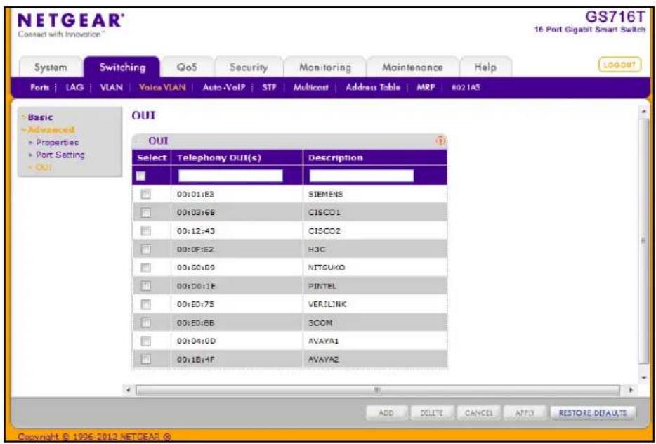
To configure OUI settings:
- To add a new OUI prefix, type the VOIP OUI prefix in the Telephony OUI(s) field, provide a description of the prefix, and click Add. The OUI prefix must be in the format AA:BB:CC.
- To delete an OUI prefix from the list, select the check box next to the OUI prefix and click Delete.
- To modify information for an entry in the OUI list, select the check box next to the OUI prefix, update the OUI prefix or description, and then click Apply.
- Click Cancel to cancel the configuration on the screen and reset the data on the screen to the latest value of the switch.
- Click Restore Defaults to restore the list to the preconfigured OUIs.
Auto-VoIP Configuration
The Auto-VoIP automatically makes sure that time-sensitive voice traffic is given priority over data traffic on ports that have this feature enabled. Auto-VoIP checks for packets carrying the following VoIP protocols:
• Session Initiation Protocol (SIP)
• H.323
• Skinny Client Control Protocol (SCCP)
VoIP frames that are received on ports that have the Auto-VoIP feature enabled are marked with CoS Traffic Class 3.
Use the Auto-VoIP Configuration menu to configure the Auto-VoIP parameters. Interface specifies all the configurable Auto-VoIP interfaces. Traffic Class displays the Traffic Class on which the received VoIP frames are marked.
To display the Auto-VoIP Configuration page, click Switching > Auto-VoIP.
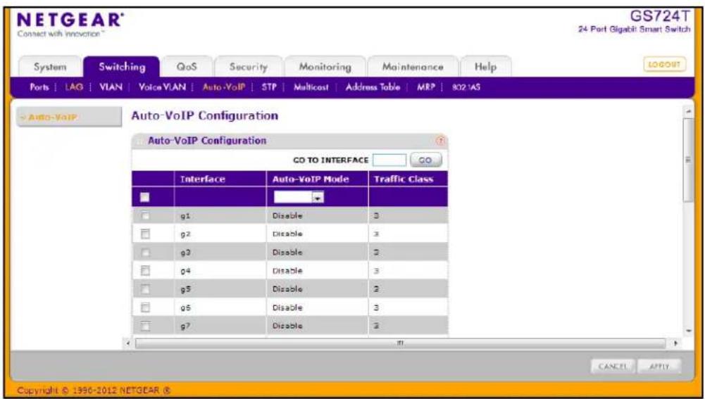
To enable Auto-VoIP:
- Auto-VoIP Mode. Select the Auto-VoIP administrative mode for the interface. This selector lists the two options for administrative mode: Enable and Disable. The administrative mode of Auto-VoIP is disabled by default.
- Click Cancel to cancel the configuration on the screen and reset the data on the screen to the latest value of the switch.
- If you make any configuration changes, click Apply to send the updated configuration to the switch. Configuration changes occur immediately.
Spanning Tree Protocol
The Spanning Tree Protocol (STP) provides a tree topology for any arrangement of bridges. STP also provides one path between end stations on a network, eliminating loops. Spanning tree versions supported include Common STP, Multiple STP, and Rapid STP.
Classic STP provides a single path between end stations, avoiding and eliminating loops. For information on configuring Common STP, see CST Port Configuration on page 103.
Multiple Spanning Tree Protocol (MSTP) supports multiple instances of Spanning Tree to efficiently channel VLAN traffic over different interfaces. Each instance of the Spanning Tree behaves in the manner specified in IEEE 802.1w, Rapid Spanning Tree (RSTP), with slight modifications in the working but not the end effect (chief among the effects, is the rapid transitioning of the port to 'Forwarding'). The difference between the RSTP and the traditional STP (IEEE 802.1D) is the ability to configure and recognize full-duplex connectivity and ports which are connected to end stations, resulting in rapid transitioning of the port to 'Forwarding' state and the suppression of Topology Change Notification. These features are represented by the parameters 'pointtopoint' and 'edgeport'. MSTP is compatible to both RSTP and STP. It behaves appropriately to STP and RSTP bridges. A MSTP bridge can be configured to behave entirely as a RSTP bridge or a STP bridge.
Note: For two bridges to be in the same region, the force version should be 802.1s and their configuration name, digest key, and revision level should match. For additional information about regions and their effect on network topology, refer to the IEEE 802.1Q standard.
The Spanning Tree folder contains links to the following features:
• STP Switch Configuration on page 100
• CST Configuration on page 102
• CST Port Configuration on page 103
• CST Port Status on page 105
• Rapid STP on page 106
• MST Configuration on page 107
• MST Port Configuration on page 109
• STP Statistics on page 111
STP Switch Configuration
The Spanning Tree Switch Configuration/Status page contains fields for enabling STP on the switch.
To display the Spanning Tree Switch Configuration/Status page, click Switching > STP > Basic > STP Configuration.
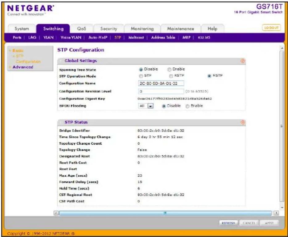
To configure STP settings on the switch:
- From the Spanning Tree State field, specify whether to enable or disable Spanning Tree operation on the switch.
- From the STP Operation Mode field, Specifies the Force Protocol Version parameter for the switch. Options are:
• STP (Spanning Tree Protocol): IEEE 802.1D
• RSTP (Rapid Spanning Tree Protocol): IEEE 802.1w
• MSTP (Multiple Spanning Tree Protocol): IEEE 802.1s
-
Specify the configuration name and revision level.
-
Configuration Name. Name used to identify the configuration currently being used. It may be up to 32 alphanumeric characters.
-
Configuration Revision Level. Number used to identify the configuration currently being used. The values allowed are between 0 and 65535. The default value is 0.
-
Specify the BPDU Flooding status for all ports or for individual ports. When this feature is enabled, BPDU packets arriving at this port are flooded to other ports if STP is disabled.
- Click Cancel to cancel the configuration on the screen and reset the data on the screen to the latest value of the switch
- If you make any configuration changes, click Apply to send the updated configuration to the switch. Configuration changes occur immediately.
The following table describes the STP Status information displayed on the screen.
| Field Description | |
| Bridge Identifier The bridge identifier for the CST. It is made up using the bridge priority and the base MAC address of the bridge. | |
| Time Since Topology Change | The time in seconds since the topology of the CST last changed. |
| Topology Change Count The number of times the topology has changed for the CST. | |
| Topology Change The value of the topology change parameter for the switch indicating if a topology change is in progress on any port assigned to the CST. The value is either True or False. | |
| Designated Root The bridge identifier of the root bridge. It is made up from the bridge priority and the base MAC address of the bridge. | |
| Root Path Cost Path cost to the Designated Root for the CST. | |
| Root Port Port to access the Designated Root for the CST. | |
| Max Age (secs) Specifies the bridge maximum age for CST. The value must be less than or equal to (2 X Bridge Forward Delay) – 1 and greater than or equal to 2 X (Bridge Hello Time +1). | |
| Forward Delay (secs) Derived value of the Root Port Bridge Forward Delay parameter. | |
| Hold Time (secs) Minimum time between transmission of Configuration BPDUs. | |
| CST Regional Root Priority and base MAC address of the CST Regional Root. | |
| CST Path Cost Path Cost to the CST tree Regional Root. | |
Click Refresh to update the information on the screen with the most current data.
CST Configuration
Use the Spanning Tree CST Configuration page to configure Common Spanning Tree (CST) and Internal Spanning Tree on the switch.
To display the Spanning Tree CST Configuration page, click Switching > STP > Advanced > CST Configuration.
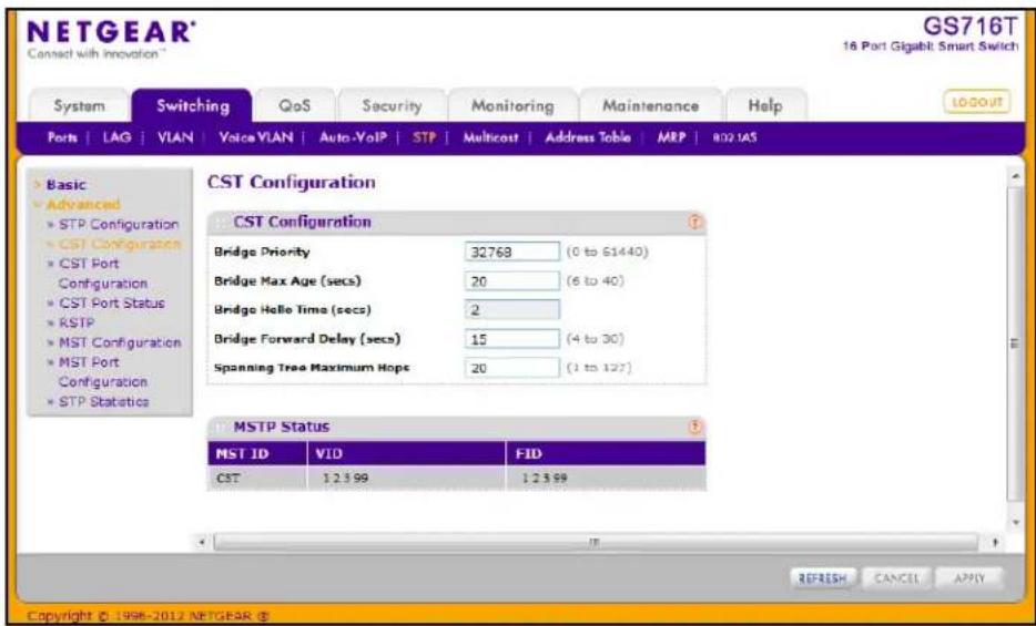
To configure CST settings:
-
Specify values for CST in the appropriate fields:
-
Bridge Priority. When switches or bridges are running STP, each is assigned a priority. After exchanging BPDUs, the switch with the lowest priority value becomes the root bridge. Specifies the bridge priority value for the Common and Internal Spanning Tree (CST). The valid range is 0–61440. The bridge priority is a multiple of 4096. If you specify a priority that is not a multiple of 4096, the priority is automatically set to the next lowest priority that is a multiple of 4096. For example, if the priority is attempted to be set to any value between 0 and 4095, it will be set to 0. The default priority is 32768.
- Bridge Max Age (secs). Specifies the bridge maximum age time for the Common and Internal Spanning Tree (CST), which indicates the amount of time in seconds a bridge waits before implementing a topological change. The valid range is 6–40, and the value must be less than or equal to (2 * Bridge Forward Delay) – 1 and greater than or equal to 2 * (Bridge Hello Time +1). The default value is 20.
- Bridge Hello Time (secs). Specifies the switch Hello time for the Common and Internal Spanning Tree (CST), which indicates the amount of time in seconds a root bridge waits between configuration messages. The value is fixed at 2 seconds.
- Bridge Forward Delay (secs). Specifies the switch forward delay time, which indicates the amount of time in seconds a bridge remains in a listening and learning state before forwarding packets. The value must be greater or equal to (Bridge Max Age / 2) + 1. The time range is from 4 seconds to 30 seconds. The default value is 15.
- Spanning Tree Maximum Hops. Specifies the maximum number of bridge hops the information for a particular CST instance can travel before being discarded. The valid range is 1–127.
- Click Cancel to cancel the configuration on the screen and reset the data on the screen to the latest value of the switch
- If you make any configuration changes, click Apply to send the updated configuration to the switch. Configuration changes take place immediately.
The following table describes the MSTP status information displayed on the Spanning Tree CST Configuration page.
| Field Description |
| MST ID Table consisting of the MST instances (including the CST) and the corresponding VLAN IDs associated with each of them. |
| VID Table consisting of the VLAN IDs and the corresponding FID associated with each of them |
| FID Table consisting of the FIDs and the corresponding VLAN IDs associated with each of them. |
Click Refresh to update the information on the screen with the most current data.
CST Port Configuration
Use the Spanning Tree CST Port Configuration page to configure Common Spanning Tree (CST) and Internal Spanning Tree on a specific port on the switch.
To display the Spanning Tree CST Port Configuration page, click Switching > STP > Advanced > CST Port Configuration.
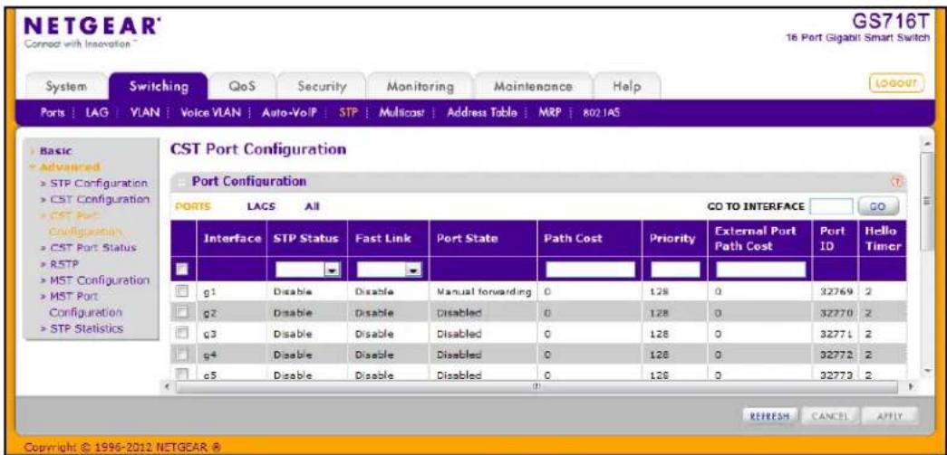
To configure CST port settings:
- To configure CST settings for a physical port, click PORTS.
- To configure CST settings for a Link Aggregation Group (LAG), click LAGS.
- To configure CST settings for both physical ports and LAGs, click ALL.
- Select the check box next to the port or LAG to configure. You can select multiple ports and LAGs to apply the same setting to the selected interfaces. Select the check box in the heading row to apply the same settings to all interfaces.
-
Configure the CST values for the selected port(s) or LAG(s):
-
STP Status. Enable or disable the Spanning Tree Protocol Administrative Mode associated with the port or port channel.
- Fast Link. Specifies if the specified port is an Edge Port with the CST. Possible values are Enable or Disable. The default is Disable.
• Port State. The Forwarding state of this port. This field is read-only. - Path Cost. Set the Path Cost to a new value for the specified port in the common and internal spanning tree. It takes a value in the range of 1–200000000.
- Priority. The priority for a particular port within the CST. The port priority is set in multiples of 16. If you specify a value that is not a multiple of 16, the priority is set to the priority is automatically set to the next lowest priority that is a multiple of 16. For example, if you set a value between 0 and 15, the priority is set to 0. If you specify a number between 16 and 31, the priority is set to 16.
- External Port Path Cost. Set the External Path Cost to a new value for the specified port in the spanning tree. It takes a value in the range of 1–200000000.
- Port ID. The port identifier for the specified port within the CST. It is made up from the port priority and the interface number of the port.
-
Hello Timer. Specifies the switch Hello time, which indicates the amount of time in seconds a port waits between configuration messages. The value is fixed at 2 seconds.
-
Click Cancel to cancel the configuration on the screen and reset the data on the screen to the latest value of the switch.
- If you make any configuration changes, click Apply to send the updated configuration to the switch. Configuration changes take place immediately.
- Click Refresh to update the information on the screen with the most current data.
CST Port Status
Use the Spanning Tree CST Port Status page to display Common Spanning Tree (CST) and Internal Spanning Tree on a specific port on the switch.
To display the Spanning Tree CST Port Status page, click Switching > STP > Advanced > CST Port Status.
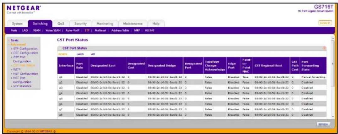
The following table describes the CST Status information displayed on the screen.
| Field Description | |
| Interface Select a physical or port channel interface to configure. The port is associated with the VLAN(s) associated with the CST. | |
| Port Role Each MST Bridge Port that is enabled is assigned a Port Role for each spanning tree. The port role will be one of the following values: Root Port, Designated Port, Alternate Port, Backup Port, Master Port, or Disabled Port. | |
| Designated Root Root Bridge for the CST. It is made up using the bridge priority and the base MAC address of the bridge. | |
| Designated Cost | Displays cost of the port participating in the STP topology. Ports with a lower cost are less likely to be blocked if STP detects loops. |
| Designated Bridge Bridge Identifier of the bridge with the Designated Port. It is made up using the bridge priority and the base MAC address of the bridge. | |
| Designated Port Port Identifier on the Designated Bridge that offers the lowest cost to the LAN. It is made up from the port priority and the interface number of the port. | |
| Topology Change Acknowledge | Identifies whether the next BPDU to be transmitted for this port would have the topology change acknowledgement flag set. It is either True or False. |
| Edge Port Indicates whether the port is enabled as an edge port. Possible values are Enabled or Disabled. | |
| Point-to-point MAC Derived value indicating whether the port is part of a point-to-point link. | |
| CST Regional Root Displays the bridge priority and base MAC address of the CST Regional Root. | |
| CST Path Cost Displays the path Cost to the CST tree Regional Root. | |
| Port Forwarding State Displays the Forwarding State of this port. | |
Click Refresh to update the information on the screen with the most current data.
Rapid STP
Use the Rapid STP page to view information about Rapid Spanning Tree (RSTP) port status. To display the Rapid STP page, click Switching >STP >Advanced >RSTP.
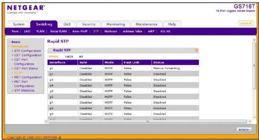
The following table describes the Rapid STP Status information displayed on the screen.
| Field Description | |
| Interface | The physical or port channel interfaces associated with VLANs associated with the CST. |
| Role Each MST Bridge | Bridge Port that is enabled is assigned a Port Role for each spanning tree.The port role will be one of the following values: Root Port, Designated Port, Alternate Port, Backup Port, Master Port, or Disabled Port. |
| Mode | Specifies the spanning tree operation mode. Different modes are STP, RSTP, and MSTP. |
| Fast Link Indicates | whether the port is enabled as an edge port. |
| Status The Forwarding | ding State of this port. |
Click Refresh to update the information on the screen with the most current data.
MST Configuration
Use the Spanning Tree MST Configuration page to configure Multiple Spanning Tree (MST) on the switch.
To display the Spanning Tree MST Configuration page, click Switching > STP > Advanced > MST Configuration.
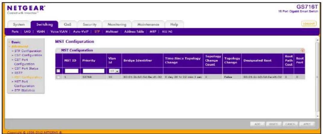
To configure an MST instance:
-
To add an MST instance, configure the MST values and click Add:
-
MST ID. Specify the ID of the MST to create. Valid values for this are between 1 and 4094.
- Priority. Specifies the bridge priority value for the MST. When switches or bridges are running STP, each is assigned a priority. After exchanging BPDUs, the switch with the lowest priority value becomes the root bridge. The bridge priority is a multiple of 4096. If you specify a priority that is not a multiple of 4096, the priority is automatically set to the next lowest priority that is a multiple of 4096. For example, if the priority is attempted to be set to any value between 0 and 4095, it will be set to 0. The default priority is 32768. The valid range is 0–61440.
-
VLAN ID. The menu contains all VLANs configured on the switch. Select a VLAN to associate with the MST instance.
-
To delete an MST instance, select the check box next to the instance and click Delete.
- To modify an MST instance, select the check box next to the instance to configure, update the values, and click Apply. You can select multiple check boxes to apply the same setting to all selected ports.
- Click Cancel to cancel the configuration on the screen and reset the data on the screen to the latest value of the switch.
For each configured instance, the information described in the following table displays on the page.
| Field Description | |
| Bridge Identifier | The bridge identifier for the selected MST instance. It is made up using the bridge priority and the base MAC address of the bridge. |
| Time Since Topology Change | Displays the total amount of time since the topology of the selected MST instance last changed. The time is displayed in hour/minute/second format, for example, 5 hours, 10 minutes, and 4 seconds. |
| Topology Change Count | Displays the total number of times topology has changed for the selected MST instance. |
| Topology Change | Indicates whether a topology change is in progress on any port assigned to the selected MST instance. The possible values are True or False. |
| Designated Root | Displays the bridge identifier of the root bridge, which is made up from the bridge priority and the base MAC address of the bridge. |
| Root Path Cost Dis | Displays the path cost to the Designated Root for this MST instance. |
| Root Port Indicates | the port to access the Designated Root for this MST instance. |
MST Port Configuration
Use the Spanning Tree MST Port Configuration page to configure and display Multiple Spanning Tree (MST) settings on a specific port on the switch.
To display the Spanning Tree MST Port Status page, click Switching > STP > Advanced > MST Port Configuration.
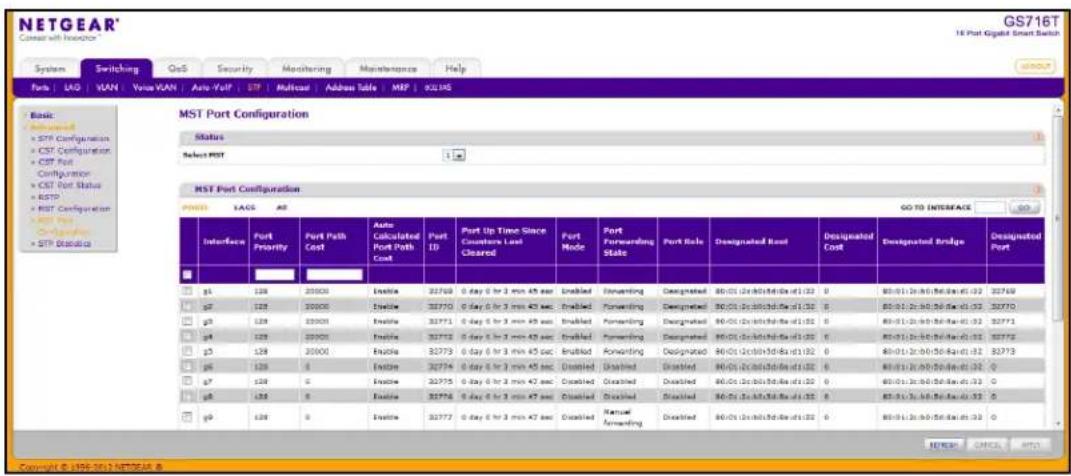
Note: If no MST instances have been configured on the switch, the page displays a "No MSTs Available" message.
To configure MST port settings:
- To configure MST settings for a physical port, click PORTS.
- To configure MST settings for a Link Aggregation Group (LAG), click LAGS.
- To configure MST settings for both physical ports and LAGs, click ALL.
- Select the check box next to the port or LAG to configure. You can select multiple ports and LAGs to apply the same setting to the selected interfaces. Select the check box in the heading row to apply the same settings to all interfaces.
- Configure the MST values for the selected port(s) or LAG(s):
- Port Priority. The priority for a particular port within the selected MST instance. The port priority is set in multiples of 16. If you specify a value that is not a multiple of 16, the priority is set to the priority is automatically set to the next lowest priority that is a multiple of 16. For example, if you set a value between 0 and 15, the priority is set to 0. If you specify a number between 16 and 31, the priority is set to 16. It takes a value in the range of 0–240.
- Port Path Cost. Set the Path Cost to a new value for the specified port in the selected MST instance. It takes a value in the range of 1–200000000.
- Click Cancel to cancel the configuration on the screen and reset the data on the screen to the latest value of the switch
- If you make any configuration changes, click Apply to send the updated configuration to the switch. Configuration changes take place immediately.
The following table describes the read-only MST port configuration information displayed on the Spanning Tree CST Configuration page
| Field Description | |
| Auto-calculated Port Path Cost | Displays whether the path cost is automatically calculated (Enabled) or not (Disabled). Path cost is calculated based on the link speed of the port if the configured value for Port Path Cost is zero. |
| Port ID The port identifier for the specified port within the selected MST instance. It is made up from the port priority and the interface number of the port. | |
| Port Up Time Since Counters Last Cleared | Time since the counters were last cleared, displayed in Days, Hours, Minutes, and Seconds. |
| Port Mode Spanning Tree Protocol Administrative Mode associated with the port or port channel. Possible values are Enable or Disable. | |
| Port Forwarding State Indicates the current STP state of a port. If enabled, the port state determines what forwarding action is taken on traffic. Possible port states are:Disabled: STP is currently disabled on the port. The port forwards traffic while learning MAC addresses.Blocking: The port is currently blocked and cannot be used to forward traffic or learn MAC addresses.Listening: The port is currently in the listening mode. The port cannot forward traffic nor can it learn MAC addresses.Learning: The port is currently in the learning mode. The port cannot forward traffic, however, it can learn new MAC addresses.Forwarding: The port is currently in the forwarding mode. The port can forward traffic and learn new MAC addresses | |
| Port Role Each MST Bridge Port that is enabled is assigned a Port Role for each spanning tree. The port role will be one of the following values: Root Port, Designated Port, Alternate Port, Backup Port, Master Port, or Disabled Port. | |
| Designated Root Root Bridge for the selected MST instance. It is made up using the bridge priority and the base MAC address of the bridge. | |
| Designated Cost | Displays cost of the port participating in the STP topology. Ports with a lower cost are less likely to be blocked if STP detects loops. |
| Designated Bridge Identifier of the bridge with the Designated Port. It is made up using the bridge priority and the base MAC address of the bridge. | |
| Designated Port Port Identifier on the Designated Bridge that offers the lowest cost to the LAN. It is made up from the port priority and the interface number of the port. | |
Click Refresh to update the screen with the latest MST information.
STP Statistics
Use the Spanning Tree Statistics page to view information about the number and type of bridge protocol data units (BPDUs) transmitted and received on each port.
To display the Spanning Tree Statistics page, click Switching > STP > Advanced > STP Statistics.
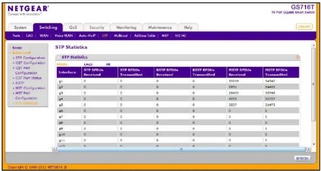
The following table describes the information available on the STP Statistics page.
| Field Description | |
| Interface Select a physical or port channel interface to view its statistics. | |
| STP BPDUs Received Number of STP BPDUs received at the selected port. | |
| STP BPDUs Transmitted Number of STP BPDUs transmitted from the selected port. | |
| RSTP BPDUs Received Number of RSTP BPDUs received at the selected port. | |
| RSTP BPDUs Transmitted Number of RSTP BPDUs transmitted from the selected port. | |
| MSTP BPDUs Received Number of MSTP BPDUs received at the selected port. | |
| MSTP BPDUs Transmitted Number of MSTP BPDUs transmitted from the selected port. | |
Click Refresh to update the screen with the latest STP statistics information.
Multicast
Multicast IP traffic is traffic that is destined to a host group. Host groups are identified by class D IP addresses, which range from 224.0.0.0 to 239.255.255.255.
From the Multicast link, you can access the following pages:
• Auto-Video Configuration on page 112
• IGMP Snooping on page 113
• IGMP Snooping Querier on page 124
Auto-Video Configuration
The Auto-Video Configuration feature is intended to support surveillance cameras and other applications running multicast traffic. Use this menu to configure the Auto-Video parameters. When the Auto-Video feature is being enabled, it configures the IGMP Snooping and IGMP Snooping Querier to operate in the Auto-Video VLAN by default. Auto-Video displays the auto-configured IGMP snooping VLAN.
To display the Auto-Video Configuration page, click Switching > Multicast > Auto-Video.
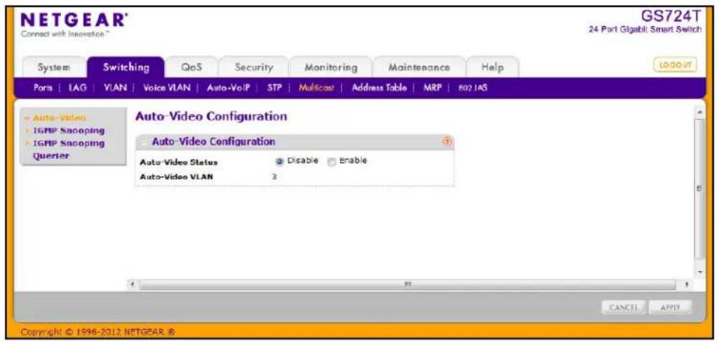
To enable Auto-Video Configuration:
- Auto-Video Status. Select the Auto-Video administrative mode for the switch. This selector lists the two options for administrative mode: enable and disable.
The Auto-Video VLAN field identifies the VLAN ID used for multicast video traffic. - Click Cancel to cancel the configuration on the screen and reset the data on the screen to the latest value of the switch.
- If you make any configuration changes, click Apply to send the updated configuration to the switch. Configuration changes occur immediately.
IGMP Snooping
Internet Group Management Protocol (IGMP) Snooping is a feature that allows a switch to forward multicast traffic intelligently on the switch. Multicast IP traffic is traffic that is destined to Del Road, greases, host group, are identified by class
224.0.0.0 to 239.255.255.255. Based on the IGMP query and report messages, the switch forwards traffic only to the ports that request the multicast traffic. This prevents the switch from broadcasting the traffic to all ports and possibly affecting network performance.
A traditional Ethernet network may be separated into different network segments to prevent placing too many devices onto the same shared media. Bridges and switches connect these segments. When a packet with a broadcast or multicast destination address is received, the switch will forward a copy into each of the remaining network segments in accordance with the IEEE MAC Bridge standard. Eventually, the packet is made accessible to all nodes connected to the network.
This approach works well for broadcast packets that are intended to be seen or processed by all connected nodes. In the case of multicast packets, however, this approach could lead to less efficient use of network bandwidth, particularly when the packet is intended for only a small number of nodes. Packets will be flooded into network segments where no node has any interest in receiving the packet. While nodes will rarely incur any processing overhead to filter packets addressed to unrequested group addresses, they are unable to transmit new packets onto the shared media for the period of time that the multicast packet is flooded. The problem of wasting bandwidth is even worse when the LAN segment is not shared, for example in full-duplex links.
Allowing switches to snoop IGMP packets is a creative effort to solve this problem. The switch uses the information in the IGMP packets as they are being forwarded throughout the network to determine which segments should receive packets directed to the group address.
The IGMP Snooping feature contains links to the following pages:
- IGMP Snooping Configuration on page 114
- IGMP Snooping Interface Configuration on page 115
• IGMP Snooping Table on page 117
• Multicast Forwarding Database Table on page 118
• MFDB Statistics on page 120 - IGMP Snooping VLAN Configuration on page 121
- Multicast Router Configuration on page 122
- Multicast Router VLAN Configuration on page 123
IGMP Snooping Configuration
Use the IGMP Snooping Configuration page to configure the parameters for IGMP snooping, which is used to build forwarding lists for multicast traffic.
To access the IGMP Snooping Configuration page, click Switching > Multicast > IGMP Snooping > IGMP Snooping Configuration.
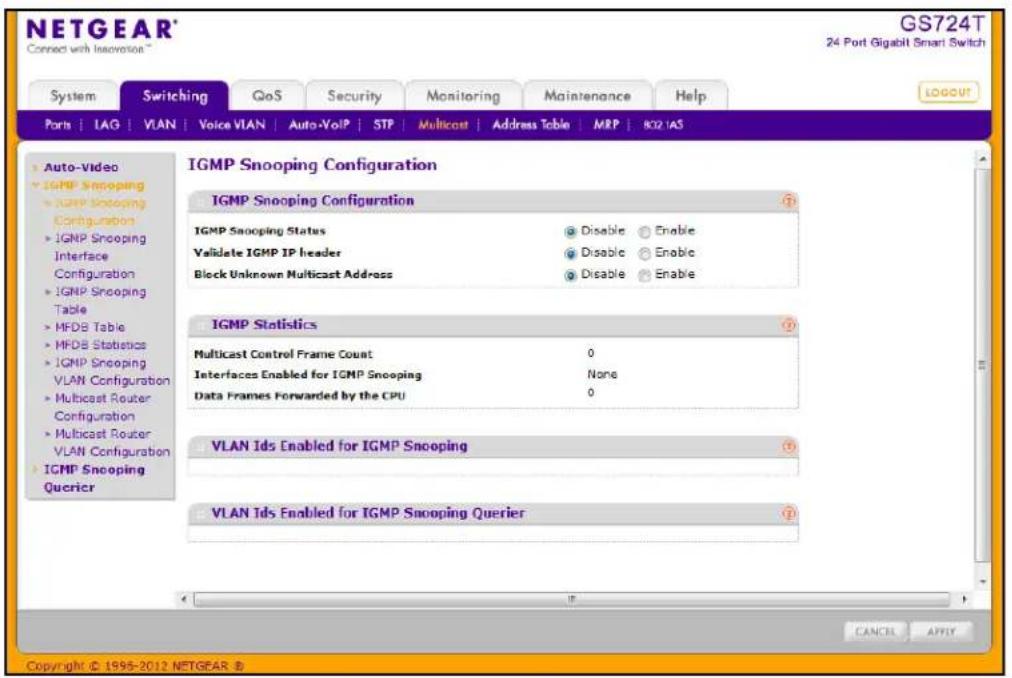
To configure IGMP Snooping:
-
Enable or disable IGMP Snooping on the switch.
-
Enable. The switch snoops all IGMP packets it receives to determine which segments should receive packets directed to the group address.
-
Disable. The switch does not snoop IGMP packets.
-
Choose whether to validate the IGMP IP header.
-
Enable. The switch checks the IP header of all IGMP messages for the Router Alert option. If the option is not present, the packet is dropped.
-
Disable. The IGMP IP header is not checked for Router Alert option.
-
Choose whether to block unknown multicast addresses.
-
Enable. Packets with unknown multicast MAC address in the destination field will be dropped.
-
Disable. Packets with unknown destination multicast MAC addresses are processed.
-
Click Apply to send the updated configuration to the switch. Configuration changes take effect immediately.
-
Click Cancel to cancel the configuration on the screen and reset the data on the screen to the latest value of the switch
The following table displays information about the global IGMP snooping status and statistics on the page.
| Field Description | |
| Multicast Control Frame Count | Displays the number of multicast control frames that have been processed by the CPU. |
| Interfaces Enabled for IGMP Snooping | Lists the interfaces currently enabled for IGMP Snooping. To enable interfaces for IGMP snooping, see IGMP Snooping Interface Configuration on page 115. |
| Data Frames Forwarded by the CPU | Displays the number of data frames forwarded by the CPU. |
| VLAN Ids Enabled For IGMP Snooping | Displays VLAN IDs enabled for IGMP snooping. To enable VLANs for IGMP snooping, see IGMP Snooping VLAN Configuration on page 121. |
| VLAN Ids Enabled For IGMP Snooping Querier | Displays VLAN IDs enabled for IGMP snooping querier. |
IGMP Snooping Interface Configuration
Use the IGMP Snooping Interface Configuration page to configure IGMP snooping settings on specific interfaces.
To access the IGMP Snooping Interface Configuration page, click Switching > Multicast > IGMP Snooping > IGMP Snooping Interface Configuration.
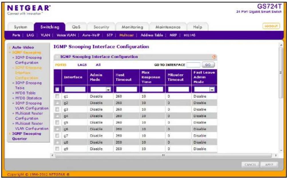
To configure IGMP Snooping interface settings:
- To configure IGMP Snooping settings for a physical port, click PORTS.
- To configure IGMP Snooping settings for a Link Aggregation Group (LAG), click LAGS.
- To configure IGMP Snooping settings for both physical ports and LAGs, click ALL.
-
Select the check box next to the port or LAG to configure. You can select multiple ports and LAGs to apply the same setting to the selected interfaces. Select the check box in the heading row to apply the same settings to all interfaces.
-
Configure the IGMP Snooping values for the selected port(s) or LAG(s):
-
Admin Mode. Use the menu to enable or disable the administrative mode of IGMP snooping on the selected interface(s). The default is Disable.
- Host Timeout. Specify the amount of time you want the switch to wait for a report for a particular group on a particular interface before it deletes that interface from the group. Enter a value between 2 and 3600 seconds. The default is 260 seconds.
- Max Response Time. Specify the amount of time you want the switch to wait after sending a query on an interface because it did not receive a report for a particular group on that interface. Enter a value greater or equal to 1 and less than the Host Timeout, in seconds. The default is 10 seconds.
- MRouter Timeout. Specify the amount of time you want the switch to wait to receive a query on an interface before removing it from the list of interfaces with multicast routers attached. Enter a value between 0 and 3600 seconds. The default is 0 seconds. A value of zero indicates an infinite timeout; no expiration.
-
Fast Leave Admin Mode. Select the Fast Leave mode for a particular interface from the menu. The default is Disable.
-
Click Cancel to cancel the configuration on the screen and reset the data on the screen to the latest value of the switch.
- If you make any configuration changes, click Apply to apply the new settings to the switch. Configuration changes take effect immediately.
IGMP Snooping Table
Use the IGMP Snooping Table page to view all of the entries in the Multicast Forwarding Database that were created for IGMP snooping.
To access the IGMP Snooping Table page, click Switching > Multicast > IGMP Snooping > IGMP Snooping Table.
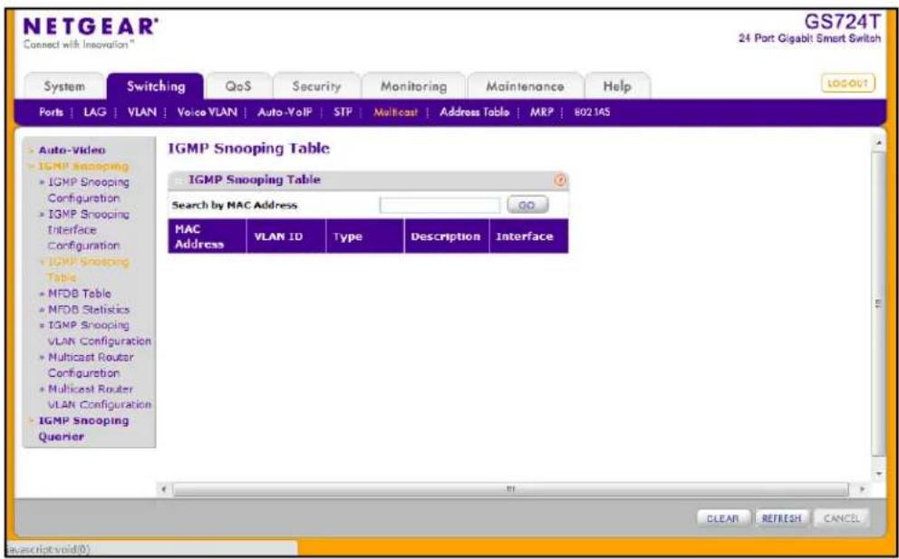
The following table describes the fields in the IGMP Snooping Table.
| Field Description | |
| MAC Address A multicast MAC | address for which the switch has forwarding and/or filtering information. The format is 6 two-digit hexadecimal numbers that are separated by colons, for example, 01:00:5e:45:67:89. |
| VLAN ID A VLAN ID for which | the switch has forwarding and filtering information. |
| Type This displays the type of | the entry. Static entries are those that are configured by the end user. Dynamic entries are added to the table as a result of a learning process or protocol. |
| Description The text description | of this multicast table entry. Possible values are Management Configured, Network Configured, and Network Assisted. |
| Interface The list of interfaces | that are designated for forwarding (Fwd) and filtering (Flt) for the associated address. |
Use the buttons at the bottom of the page to perform the following actions:
- Click Clear to clear one or all of the IGMP Snooping entries.
- Click Refresh to reload the page and display the most current information.
Multicast Forwarding Database Table
The Layer 2 Multicast Forwarding Database (MFDB) is used by the switch to make forwarding decisions for packets that arrive with a multicast destination MAC address. By limiting multicasts to only certain ports in the switch, traffic is prevented from going to parts of the network where that traffic is unnecessary.
When a packet enters the switch, the destination MAC address is combined with the VLAN ID and a search is performed in the Layer 2 Multicast Forwarding Database. If no match is found, then the packet is either flooded to all ports in the VLAN or discarded, depending on the switch configuration. If a match is found, then the packet is forwarded only to the ports that are members of that multicast group.
Use the MFDB Table page to view the port membership information for all active multicast address entries. The key for an entry consists of a MAC address. Entries may contain data for more than one protocol.
To access the MFDB Table page, click Switching > Multicast > IGMP Snooping > MFDB Table.
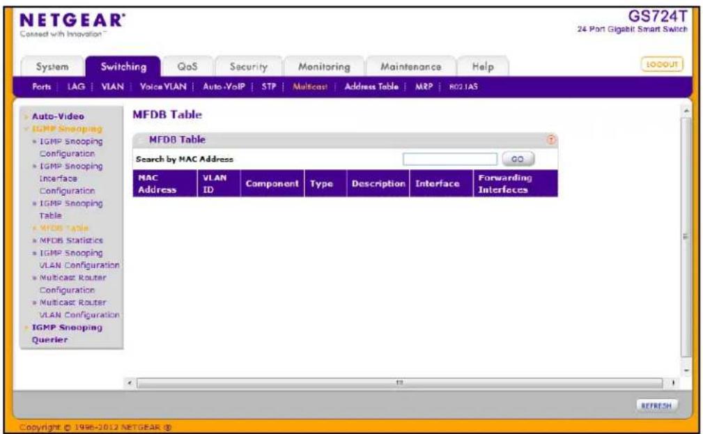
The following table describes the fields in the MFDB Table.
| Field Description | |
| MAC Address The MAC | Address to which the multicast MAC address is related.To search by MAC address, enter the address with the MFDB table entry you want displayed. Enter six two-digit hexadecimal numbers separated by colons, for example 00:0f:43:67:89:AB, and then click Go. If the address exists, that entry will be displayed. An exact match is required. |
| VLAN ID The VLAN ID | to which the multicast MAC address is related. |
| Component This is the | component that is responsible for this entry in the Multicast Forwarding Database. Possible values are IGMP Snooping or Static Filtering. |
| Type | This displays the type of the entry. Static entries are those that are configured by the end user. Dynamic entries are added to the table as a result of a learning process or protocol. |
| Description The text de | description of this multicast table entry. Possible values are Management Configured, Network Configured, and Network Assisted. |
| Interface The list of int | faces that are designated for forwarding (Fwd) and filtering (Flt) for the selected address. |
| Forwarding Interfaces | The resultant forwarding list is derived from combining all the forwarding interfaces and removing the interfaces that are listed as the static filtering interfaces. |
Click Refresh to update the information on the screen with the most current data.
MFDB Statistics
Use the multicast forwarding database Statistics page to view statistical information about the MFDB table.
To access the MFDB Statistics page, click Switching > Multicast > IGMP Snooping > MFDB Statistics.
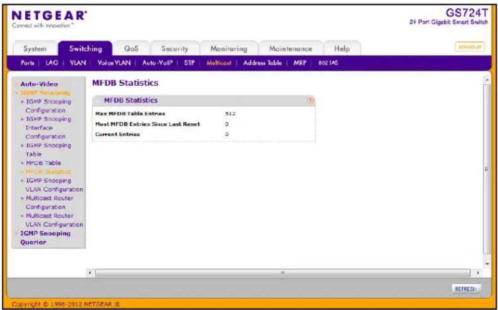
The following table describes the information available on the MFDB Statistics page:
| Field Description | |
| Max MFDB Table Entries | Displays the maximum number of entries that the Multicast Forwarding Database table can hold. |
| Most MFDB Entries Since Last Reset | The largest number of entries that have been present in the Multicast Forwarding Database table since the system was last reset. This value is also known as the MFDB high-water mark. |
| Current Entries | Displays the current number of entries in the Multicast Forwarding Database table. |
Click Refresh to update the information on the screen with the most current data.
IGMP Snooping VLAN Configuration
Use the IGMP Snooping VLAN Configuration page to configure IGMP snooping settings for VLANs on the system.
To access the IGMP Snooping VLAN Configuration page, click Switching > Multicast > IGMP Snooping > IGMP Snooping VLAN Configuration.
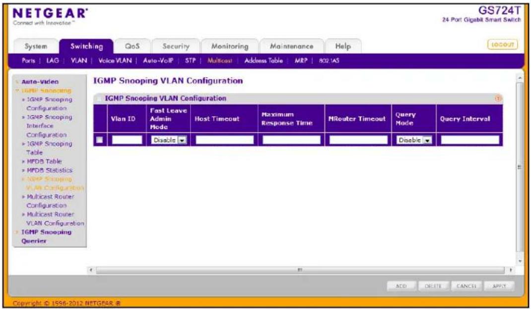
To configure IGMP snooping settings for VLANs:
-
To enable IGMP snooping on a VLAN, enter the VLAN ID in the appropriate field and configure the IGMP Snooping values:
-
Fast Leave Admin Mode. Enable or disable the IGMP Snooping Fast Leave Mode for the specified VLAN ID. Enabling fast-leave allows the switch to immediately remove the layer 2 LAN interface from its forwarding table entry upon receiving an IGMP leave message for that multicast group without first sending out MAC-based general queries to the interface. You should enable fast-leave admin mode only on VLANs where only one host is connected to each layer 2 LAN port. This prevents the inadvertent dropping of the other hosts that were connected to the same layer 2 LAN port but were still interested in receiving multicast traffic directed to that group. Also, fast-leave processing is supported only with IGMP version 2 hosts.
-
Host Timeout. Sets the value for group membership interval of IGMP snooping for the specified VLAN ID. The valid range is (Maximum Response Time + 1) to 3600 seconds.
• Maximum Response Time. Enter the amount of time in seconds that a switch will wait after sending a query on the VLAN because it did not receive a report for a particular group in that interface. value. The valid range is 1 to 25 seconds. Its value must be less than the Host Timeout value. -
MRouter Timeout. Enter the amount of time that a switch will wait to receive a query on the VLAN before removing it from the list of VLANs with multicast routers attached. Enter a value between 0 and 3600 seconds. The default is 0 seconds, which means there is no expiration.
- Query Mode. Enable or disable the IGMP Querier Mode for the specified VLAN ID.
-
Query Interval. Enter the value for IGMP Query Interval for the specified VLAN ID. The valid range is 1–1800 seconds. The default is 60 seconds.
-
Click Add to enable IGMP snooping and the associated settings on the specified VLAN.
- To disable IGMP snooping on a VLAN and remove it from the list, select the check box next to the VLAN ID and click Delete.
- To modify IGMP snooping settings for a VLAN, select the check box next to the VLAN ID, update the desired values, and click Apply.
- Click Cancel to cancel the configuration on the screen and reset the data on the screen to the latest value of the switch.
Multicast Router Configuration
This page configures the interface as the one the multicast router is attached to. All IGMP packets snooped by the switch will be forwarded to the multicast router reachable from this interface. The configuration is not needed most of the time since the switch will automatically detect the presence of multicast router and forward IGMP packet accordingly. It is only needed when you want to make sure the multicast router always receives IGMP packets from the switch in a complex network.
To access the Multicast Router Configuration page, click Switching > Multicast > IGMP Snooping > Multicast Router Configuration.
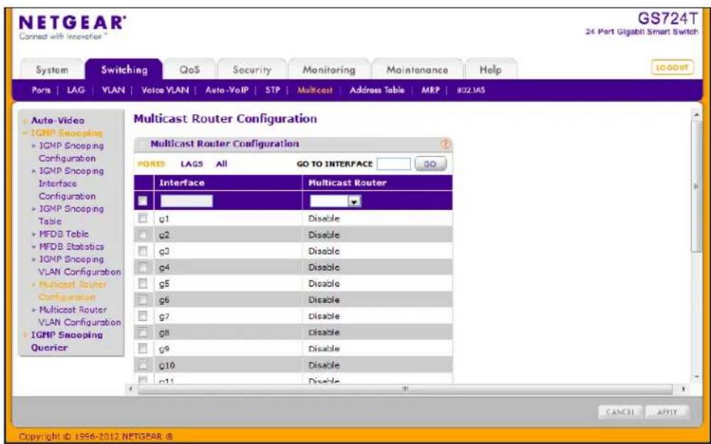
To configure the multicast router settings:
- Select the check box associated with each interface you want to configure. Select the check box in the heading row to apply the same settings to all interfaces.
- Use Multicast Router to enable or disable Multicast Router on the selected interfaces.
- Click APPLY to update the switch with the changes.
- Click CANCEL to abandon the changes.
Multicast Router VLAN Configuration
This page configures the interface to only forward the snooped IGMP packets that come from the specified VLAN to the multicast router attached to this interface. The configuration is not needed most of the time since the switch will automatically detect the presence of a multicast router and forward IGMP packets accordingly. It is only needed when you want to make sure that the multicast router always receives IGMP packets from the switch in a complex network.
To access the Multicast Router VLAN Configuration page, click Switching > Multicast > IGMP Snooping > Multicast Router VLAN Configuration.
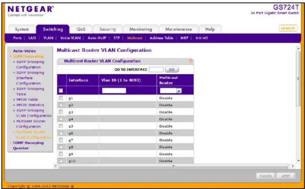
To configure the multicast router VLAN settings:
- Select the check box associated with each interface you want to configure. Select the check box in the heading row to apply the same settings to all interfaces.
- Use VLAN ID to select the VLAN ID for which the Multicast Router Mode is to be Enabled or Disabled.
- Use Multicast Router to enable or disable multicast router for the VLAN ID.
- Click APPLY to update the switch with the changes.
- Click CANCEL to abandon the changes.
IGMP Snooping Querier
IGMP snooping requires that one central switch or router periodically query all end-devices on the network to announce their multicast memberships. This central device is the IGMP querier. The IGMP query responses, known as IGMP reports, keep the switch updated with the current multicast group membership on a port-by-port basis. If the switch does not receive updated membership information in a timely fashion, it will stop forwarding multicasts to the port where the end device is located.
These pages enable you to configure and display information on IGMP snooping queriers on the network and, separately, on VLANs.
The IGMP Snooping Querier feature contains links to the following pages:
• IGMP Snooping Querier Configuration on page 124
- IGMP Snooping Querier VLAN Configuration on page 126
• IGMP Snooping Querier VLAN Status on page 127
IGMP Snooping Querier Configuration
Use this page to enable or disable the IGMP Snooping Querier feature, specify the IP address of the router to perform the querying, and configure the related parameters.
To access this page, click Switching > Multicast > IGMP Snooping Querier > IGMP Snooping > Querier Configuration.
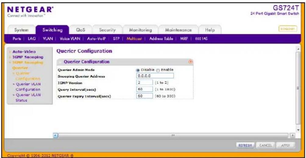
To configure IGMP Snooping Querier settings:
-
From the Querier Admin Mode field, enable or disable the administrative mode for IGMP Snooping Querier.
-
In the Snooping Querier Address field, specify the IP address to be used as source address in periodic IGMP queries. This address is used when no address is configured on the VLAN on which the query is being sent.
- In the IGMP Version field, specify the IGMP protocol version used in periodic IGMP queries.
- In the Query Interval field, specify the time interval in seconds between periodic queries sent by the snooping querier. The Query Interval must be a value in the range of 1–1800 seconds. The default value is 60.
- In the Querier Expiry Interval field, specify the time interval in seconds after which the last querier information is removed. The Querier Expiry Interval must be a value in the range of 60–300 seconds. The default value is 60.
- Click Cancel to cancel the configuration on the screen and reset the data on the screen to the latest value of the switch.
- Click Apply to apply the new settings to the switch. Configuration changes take effect immediately
- Click Refresh to update the page with the latest information from the switch.
IGMP Snooping Querier VLAN Configuration
Use this page to configure IGMP queriers for use with VLANs on the network.
To access this page, click Switching > Multicast > IGMP Snooping Querier > Querier VLAN Configuration.
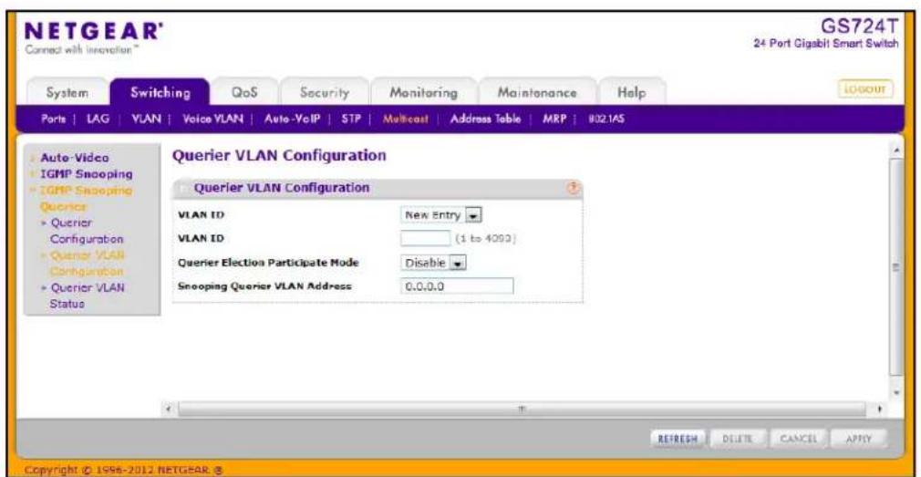
To configure Querier VLAN settings:
- To create a new VLAN ID for IGMP Snooping, select New Entry from the VLAN ID field and complete the following fields:
• VLAN ID. Specifies the VLAN ID for which the IGMP Snooping Querier is to be enabled.
• Querier Election Participate Mode. Enable or disable Querier Participate Mode.
- Disabled. Upon seeing another querier of the same version in the VLAN, the snooping querier moves to the non-querier state.
- Enabled. The snooping querier participates in querier election, in which the least IP address operates as the querier in that VLAN. The other querier moves to non-querier state.
- Snooping Querier VLAN Address. Specify the Snooping Querier IP Address to be used as the source address in periodic IGMP queries sent on the specified VLAN.
- Click Apply to apply the new settings to the switch. Configuration changes take effect immediately
- To disable Snooping Querier on a VLAN, select the VLAN ID and click Delete.
- Click Cancel to cancel the configuration on the screen and reset the data on the screen to the latest value of the switch.
- Click Refresh to update the page with the latest information from the switch.
IGMP Snooping Querier VLAN Status
Use this page to view the operational state and other information for IGMP snooping queriers for VLANs on the network.
To access this page, click Switching > Multicast > IGMP Snooping Querier > Querier VLAN Status.
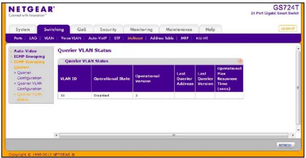
The following table describes the information available on the Querier VLAN Status page.
| Field Description | |
| VLAN ID Specifies the VLAN ID | on which the IGMP Snooping Querier is administratively enabled and for which VLAN exists in the VLAN database. |
| Operational State Specifies the operational state of the IGMP Snooping Querier on a VLAN:Querier:The snooping switch is the querier in the VLAN. The snooping switch will send out periodic queries with a time interval equal to the configured querier query interval. If the snooping switch sees a better querier (numerically lower) in the VLAN, it moves to non-querier mode.Non-Querier:The snooping switch is in non-querier mode in the VLAN. If the querier expiry interval timer expires, the snooping switch moves into querier mode.Disabled:The snooping querier is not operational on the VLAN. The snooping querier moves to disabled mode when IGMP snooping is not operational on the VLAN, when the querier address is not configured, or the network management address is not configured. | |
| Operational Version Displays the IGMP protocol version of the operational querier. | |
| Last Querier Address | Displays the IP address of the last querier from which a query was snooped on the VLAN. |
| Last Querier Version Displays | the IGMP protocol version of the last querier from which a query was snooped on the VLAN. |
| Operational Max Response Time | Displays the maximum response time to be used in the queries that are sent by the snooping querier. |
Click Refresh to redisplay the page with the latest information from the switch.
Address Table
The address table, also known as the forwarding database, maintains a list of MAC addresses after having received a packet from this MAC address. The transparent bridging function uses the forwarding database entries to determine how to forward a received frame.
The Address Table folder contains links to the following features:
• MAC Address Table on page 128
• Dynamic Address Configuration on page 130
• Static MAC Address on page 131
MAC Address Table
The MAC Address Table contains information about unicast entries for which the switch has forwarding and/or filtering information. This information is used by the transparent bridging function in determining how to propagate a received frame. Use the search function of the MAC Address Table page to display information about the entries in the table.
To access this page, click Switching > Address Table > Basic > Address Table.
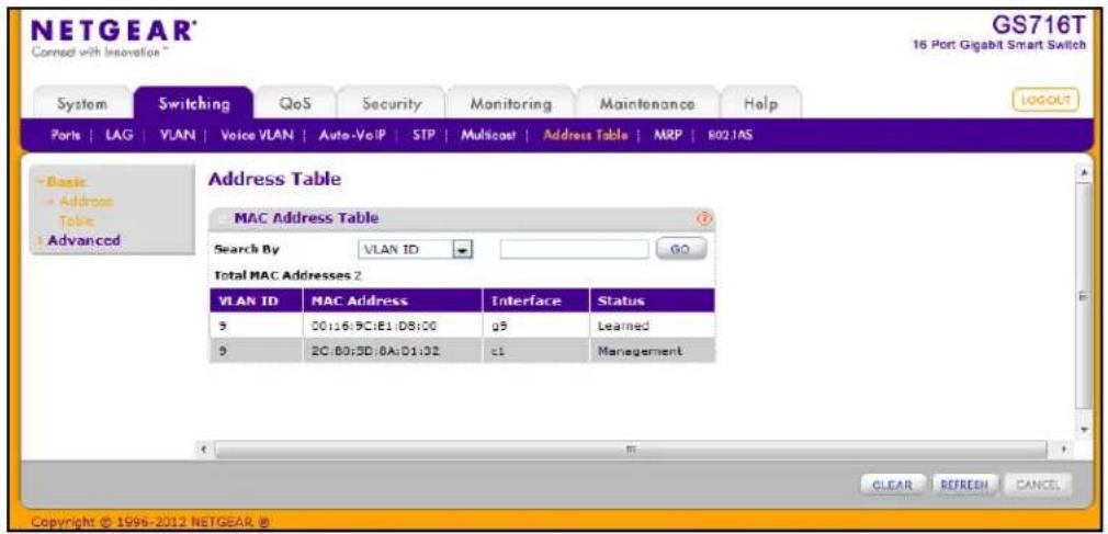
To search for an entry in the MAC Address Table:
-
Use the Search By field to search for MAC Addresses by MAC Address, VLAN ID, or Interface.
-
MAC Address: Select MAC Address from the menu and enter a six-byte hexadecimal MAC address in two-digit groups separated by colons, then click Go. If the address exists, that entry will be displayed. An exact match is required.
- VLAN ID: Select VLAN ID from the menu, enter the VLAN ID, for example, 100. Then click Go. If any entries with that VLAN ID exist they are displayed.
-
Interface: Select Interface from the menu, enter the interface ID in g1, g2... format, then, click Go. If any entries learned on that interface exist, they are displayed.
-
Click Clear to clear Dynamic MAC Addresses in the table.
- Click Refresh to redisplay the page to show the latest MAC Addresses.
- Click Cancel to cancel the configuration on the screen and reset the data on the screen to the latest value of the switch.
The following table describes the information available for each entry in the address table.
| Field Description | |
| VLAN ID Specifies the VLAN ID | on which the IGMP Snooping Querier is administratively enabled and for which VLAN exists in the VLAN database. |
| MAC Address A unicast MAC | address for which the switch has forwarding and/or filtering information. The format is a six-byte MAC address with each byte separated by colons. For example, 00:0F:89:AB:CD:EF. |
| Interface The port where this address was learned: that is, this field displays the port through which the MAC address can be reached. | |
| Status The status of this entry. | The possible values are:Static:The entry was added when a static MAC filter was defined.Learned:The entry was learned by observing the source MAC addresses of incoming traffic, and is currently in use.Management:The system MAC address, which is identified with interface c1. |
Dynamic Address Configuration
Use the Dynamic Addresses page to set the amount of time to keep a learned MAC address entry in the forwarding database. The forwarding database contains static entries, which are never aged out, and dynamically learned entries, which are removed if they are not updated within a given time.
To access the Configuration page, click Switching > Address Table > Advanced > Dynamic Addresses.
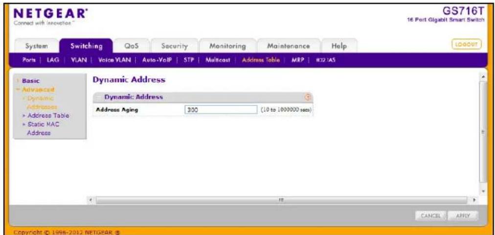
To configure the Dynamic Address setting:
- Specify the number of seconds the forwarding database should wait before deleting a learned entry that has not been updated. IEEE 802.1D-1990 recommends a default of 300 seconds. You may enter any number of seconds between 10 and 1000000. The factory default is 300.
Note: IEEE 802.1D recommends a default of 300 seconds, which is the factory default.
- Click Cancel to cancel the configuration on the screen and reset the data on the screen to the latest value of the switch.
- Click Apply to apply to send the updated configuration to the switch. Configuration changes take effect immediately.
Static MAC Address
Use the Static MAC Address Configuration page to configure and view static MAC addresses on an interface.
To access the Static MAC Address Configuration page, click Switching > Address Table > Advanced > Static MAC Address.
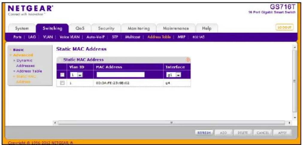
To configure a static MAC address:
- To add a static MAC address entry
a. From the Interface menu, select the port or LAG on which to configure the static MAC address.
b. Specify the MAC address to add.
c. Select the VLAN ID corresponding to the MAC address to add.
d. Click Add.
-
To delete a static MAC address, select the check box next to the entry and click Delete.
-
To modify the settings for a static MAC address, select the check box next to the entry, update the desired values, and click Apply.
-
Click Refresh to reload the page and display the latest MAC address learned on a specific port.
-
Click Cancel to cancel the configuration on the screen and reset the data on the screen to the latest value of the switch.
Multiple Registration Protocol Configuration ^1
Multiple Registration Protocol (MRP) is a base registration protocol that enables devices running an MRP application to register attributes to other devices in a network. MRP provides an application to register attributes such as bandwidth requirement for a given AV stream and MAC address information. It is used by various applications to propagate the registration. GS716T and GS724T Smart Switches support the following MRP applications:
• Multiple MAC Reservation Protocol (MMRP)
• Multiple Stream Reservation Protocol (MSRP)
MMRP allows for the propagation MAC address information in the network, and allows for the registration and deregistration of both individual MAC address information and group MAC address membership. End stations may request to join or leave a multicast group, or to register an individual MAC address with a specific VLAN. MAC address entries can be dynamically registered and deregistered if MMRP is administratively enabled on GS716T and GS724T Smart Switches.
MSRP reserves necessary resources in the network to facilitate time sensitive traffic to flow end to end. In a typical network, there are multiple Talkers (those who transmit streams) and multiple Listeners (those who receive streams from one or many Talkers). Each flow has specific bandwidth, frame rate, and time sync requirements. With the use of MSRP these resources are guaranteed through all intermediate devices that are between any talker and listener.
Note: MRP framework must be available and enabled in all intermediate devices to ensure that the propagation of the attributes occurs throughout the network.
With MRP, network attributes are declared, registered, withdrawn, and removed completely dynamically without any user intervention. This dynamic nature is especially useful in networks where:
- Network attributes are likely to change frequently, requiring reconfiguration of the intermediate devices.
• Recipients of these attributes frequently increase or decrease in number.
• Each of these changes without a dynamic self-adjusting framework would require constant attention from the network administrator.
MRP Configuration
Use the MRP Configuration page to configure global MRP settings for the switch. To access the basic MRP Configuration page click the Switching tab, then click MRP > Basic > MRP Configuration.
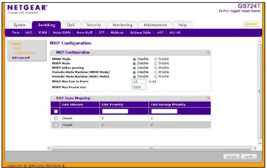
To configure the MRP settings:
- Use the MMRP Mode field to enable or disable MMRP globally on the switch. MMRP provides an application to register MAC address information. The default mode is Disable.
- Use the MSRP Mode field to enable or disable MSRP globally on the switch. MSRP provides an application to register bandwidth requirement for a given AV stream. The default mode is Disable.
- If you enable MSRP, configure the following MSRP settings:
a. Enable or disable MSRP talker pruning. The MSRP talker is the source of an AV stream. Default mode is Disable.
b. Enable or disable the MRP Periodic State Machine for MSRP on the system. Default mode is Disable.
c. In the MSRP Max Fan In Ports field, specify the maximum number of the ports where MSRP registrations are allowed.
d. In the MSRP Max Frame Size field, specify the maximum frame size allowed for an MSRP frame. The valid range for the frame size is 64–9216 octets.
-
If you enable MMRP, enable or disable the MRP Periodic State Machine for MMRP on the system. Default mode is Disable. For this setting to take effect, MMRP must be enabled, but MSRP does not need to be enabled.
-
Configure the 802.1Qav mapping for the Class A and/or Class B EAV streams. Class A streams have a higher transmission priority than Class B traffic.
-
In the EAV Priority field, specify the priority for each EAV stream class. The range is 0–7.
-
In the EAV Remap Priority field, specify the remap priority for non-EAV traffic. The range is 0–7.
-
Click Cancel to cancel the configuration on the screen and reset the data on the screen to the latest value of the switch.
-
If you make any changes to the page, click Apply to apply the change to the system.
MRP Port Settings
Use the MRP Port Settings page to configure the per-port MRP mode and timer settings. The timers control when and how often various messages are transmitted on each interface.
To access the Port Settings page click Switching > MRP > Advanced > Port Settings in the navigation tree. In the following image, the MMRP mode on ports g4 and g5 is being enabled.
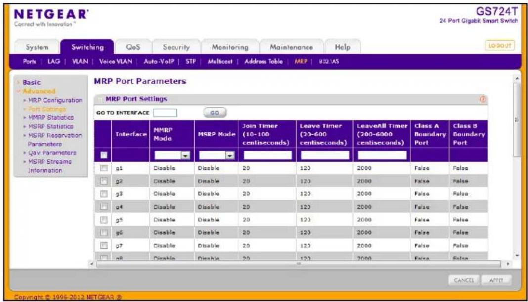
To configure the MRP port parameters:
- Select the check box next to the port to configure. You can select multiple ports to apply the same settings to the selected interfaces. Select the check box in the heading row to apply the same settings to all interfaces.
- Configure the following MRP port settings:
a. Enable or disable MMRP on the interface. The default mode is Disable.
b. Enable or disable MSRP on the interface. The default mode is Disable.
c. Specify the value, in centiseconds, of the MRP Join Timer. The range is 10 to 100 centiseconds, and the default value is 20.
d. Specify the value, in centiseconds, of the MRP Leave Timer. The range is 10 to 600 centiseconds, and the default value is 120.
e. Specify the value, in centiseconds, of the MRP LeaveAll Timer. The range is 200 to 6000 centiseconds, and the default value is 2000.
ClassA/ClassB Boundary Port fields are not configurable and show whether the interface is a boundary port.
- Click Cancel to cancel the configuration on the screen and reset the data on the screen to the latest value of the switch.
- If you make any changes to the page, click Apply to apply the change to the system.
MMRP Statistics
The MMRP Statistics page displays information regarding the MMRP frames transmitted and received by the switch and by each interface. To access the MMRP Statistics page click the Switching tab, then click MRP > Advanced > MMRP Statistics.
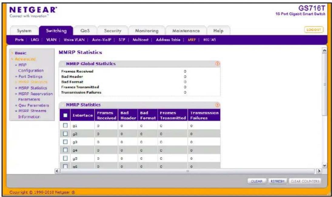
The following table describes the fields on the MMRP Statistics page.
| Field Description | |
| Global MMRP Statistics | |
| Frames Received Shows the number of MMRP frames which were received on the switch. | |
| Bad Header Shows number of MMRP frames with bad headers which were received on the switch. | |
| Bad Format Shows number of MMRP frames with bad PDUs body formats which were received on the switch. | |
| Frames Transmitted Shows number of MMRP frames which were transmitted on the switch. | |
| Transmission Failures Shows number of MMRP frames that the switch failed to transmit. | |
| Per-Interface MMRP Statistics | |
| Interface Identifies the interface associated with the rest of the MMRP statistics in the row. | |
| Frames Received Shows number of MMRP frames which were received on particular interface. | |
| Bad Header Shows number of MMRP frames with bad headers which were received on the particular interface. | |
| Bad Format Shows number of MMRP frames with bad PDUs body formats which were received on the particular interface. | |
| Frames Transmitted Shows number of MMRP frames which were transmitted on the interface. | |
| Transmission Failures Shows number of MMRP frames transmitting of which were failed on particular interface. | |
To reload the page, click Refresh. To clear the statistics for one or more ports, select the check box next to the interface or interfaces, and click Clear. To clear the statistics for all interfaces, select the check box in the heading row, and click Clear Counters.
MSRP Statistics
The MSRP Statistics page displays information about the MSRP frames transmitted and received by the switch and by each interface. To access the MSRP Statistics page click the Switching tab, then click MRP > Advanced > MSRP Statistics.
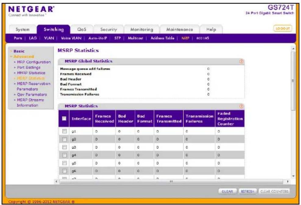
The following table describes the fields on the MSRP Statistics page.
| Field Description | |
| Global MSRP Statistics | |
| Message Queue Add Failures | Shows the number of messages that failed to be added to the queue. |
| Frames Received | Shows number of MSRP frames that have been received on the switch. |
| Bad Header | Shows number of MSRP frames with bad headers that have been received on the switch. |
| Bad Format | Shows number of MSRP frames with bad PDUs body formats that have been received on the switch. |
| Frames Transmitted | Shows number of MSRP frames which that have been transmitted on the switch. |
| Transmission Failures | Shows number of MSRP frames the switch failed to transmit. |
| Per-Interface MSRP Statistics | |
| Interface Identifies the interface | associated with the rest of the MSRP statistics in the row. |
| Frames Received Displays the | number of MSRP frames which were received the interface. |
| Bad Header Displays the number | ber of MSRP frames with bad header which were received on the interface. |
| Bad Format Displays the number | ber of MSRP frames with bad PDUs body format which were received on the interface. |
| Frames Transmitted Displays | the number of MSRP frames which were transmitted on the interface. |
| Transmission Failures Displays | the number of MSRP frames that an interface attempted to transmit but failed. |
| Failed Registration Counter | Shows the number of MSRP frames that failed to register on a device or particular interface. |
To reload the page, click Refresh. To clear the statistics for one or more ports, select the check box next to the interface or interfaces, and click Clear. To clear the statistics for all interfaces, select the check box in the heading row, and click Clear Counters.
MSRP Reservation Parameters
Use the MSRP Reservation Parameters page to view information about the talker, listener, and intermediate device status for the devices involved in each MSRP stream flowing through the switch.
To display the MSRP Reservation Parameters page, click the Switching tab, then click MRP > Advanced > MSRP Reservation Parameters.
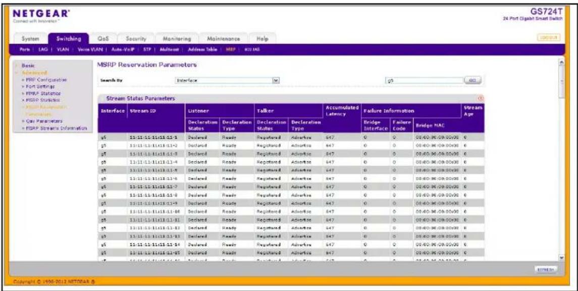
To search for a specific entry in the Stream Status Parameters table:
- To search for stream status by interface, select Interface from the drop-down menu and enter the port ID (for example, g5) in the available field.
- To search for stream status by Stream ID, select Stream ID from the drop-down menu, and enter the Stream ID (for example, 43000) in the available field.
- Click Go.
The following table describes the non-configurable fields on the MSRP Reservation Parameters page.
| Field Description | |
| Interface Identifies the interface associated with the rest of the information in the row. | |
| Stream ID A 16-bit unsigned integer value, Unique ID, used to distinguish among multiple streams sourced by the same system. | |
| Listener Declaration Status Identifies the MSRP declaration status of the listener attribute. | |
| Listener Declaration Type Identifies the MSRP declaration type of the listener attribute. | |
| Talker Declaration Status Identifies the MSRP declaration status of the talker attribute. | |
| Talker Declaration Type Identifies the MSRP declaration type of the talker attribute. | |
| Accumulated Latency Identifies how much latency, in nanoseconds, the stream has suffered in its path from the Talker to a given Listener. It starts as a 0 in a Talker Advertise Declaration at the Talker, and its value is increased by one for each bridge as the Talker Advertise Declaration propagates through the network. | |
| Failure Bridge Interface Identifies the interface on the Bridge where the failure occurred. | |
| Failure Code Shows the number that represents the reason for the failure. The switch supports the following codes:1—Insufficient bandwidth3—Insufficient bandwidth for the traffic class5—Stream destination_address is already in use7—Reported latency has changed8—Egress port is not Audio/Video Bridging (AVB) capable9—Use a different destination_address (i.e. MAC DA hash table full)12—Cannot store destination_address (i.e., Bridge is out of MAC DA resources)13—Requested priority is not an SR Class priority14—MaxFrameSize is too large for media15—msrpMaxFanInPorts limit has been reached16—Changes in FirstValue for a registered StreamID17—VLAN is blocked on this egress port (Registration Forbidden) | |
| Failure Bridge MAC Identifies the MAC address of the switch where the failure occurred. | |
| Stream Age The time, in seconds, since the stream destination address was added to the Dynamic Reservations Entries table. A value of zero indicates the destination address has not been added to the table. | |
Qav Parameters
Use the Qav Parameters page to configure and view the per-port IEEE 802.1Qav settings. The IEEE 802.1Qav standard supports time-sensitive traffic streams by pacing all switch traffic, including legacy asynchronous Ethernet traffic, through queuing and forwarding. When a Talker declares a stream, it identifies whether the stream is Class A or Class B and specifies the stream's bandwidth requirements. Class A traffic has a higher transmission priority than Class B traffic.
On the Qav Parameters page, you can view and configure selected bandwidth allocations for Class A and Class B traffic. To display the Qav Statistics page click the Switching tab, then click MRP > Advanced > Qav Parameters.
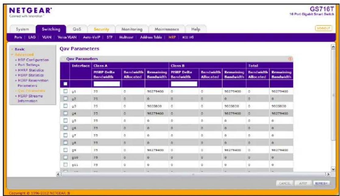
To configure the Qav parameters:
- Select the check box next to the port to configure. You can select multiple ports to apply the same settings to the selected interfaces. Select the check box in the heading row to apply the same settings to all interfaces.
- Configure the Class A MSRP delta bandwidth.
Class A Delta bandwidth is the additional bandwidth represented as a percentage of port transmit rate which can be reserved for the traffic class A and traffic class B. Class A traffic has a higher priority. The range is 0–100.
The following Class A fields are read-only:
- The Bandwidth Allocated field shows the current rate of the class A traffic on interface (in Bps).
-
The Class A Remaining Bandwidth field shows the maximum rate of the class A traffic available on interface (in Bps).
-
Configure the Class B MSRP delta bandwidth.
Class B Delta bandwidth is the additional bandwidth represented as a percentage of port transmit rate which can be reserved for the traffic class B. The range is 0–100.
The following Class B fields are read-only:
- The Bandwidth Allocated field shows the current rate of the class B traffic on interface (in Bps).
-
The Class B Remaining Bandwidth field shows the maximum rate of the class B traffic available on interface (in Bps).
-
View the following information about the total bandwidth:
-
The Total Bandwidth Allocated Sum of the allocated Class A and Class B traffic rates on interface (in Bps).
-
Total Remaining Bandwidth, which is 75% of the interface speed minus total allocated bandwidth (in Bps/sec).
-
Click Cancel to cancel the configuration on the screen and reset the data on the screen to the latest value of the switch.
-
If you make any changes to the page, click Apply to apply the change to the system.
- Click Refresh to reload the page and update it with the most current information.
MSRP Streams Information
Use the MSRP Stream Information page to view information about MSRP streams flowing through each interface. To display the MSRP Stream Information page click the Switching tab, then click MRP > Advanced > MSRP Stream Information.
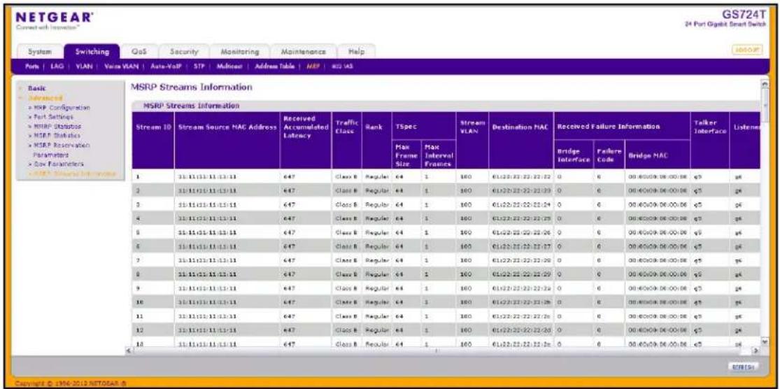
The following table describes the fields on the MSRP Stream Information page.
| FieldDescription | |
| Stream ID A 16-bit unsigned integer value, Unique ID, used to distinguish among multiple streams sourced by the same system. | |
| Stream Source MAC Address Identifies the MAC address of the traffic stream's source. | |
| Received Accumulated Latency | The 32-bit unsigned Accumulated Latency component is used to determine the worst-case latency that a Stream can suffer in its path from the Talker to a given Listener. It starts as a 0 in a Talker Advertise Declaration at the Talker, and its value is increased by each Bridge as the Talker Advertise Declaration propagates through the network. |
| Traffic Class Identifies whether the stream is Class A or Class B. Class A traffic has a higher priority than Class B traffic. | |
| Rank The 5-bit unsigned Rank component is used by systems to decide which streams can and cannot be served, when the MSRP registrations exceed the capacity of a Port to carry the corresponding data streams. If a Bridge becomes oversubscribed (e.g. network reconfiguration, 802.11 bandwidth reduction) the Rank will also be used to help determine which Stream or Streams can be dropped. A lower numeric value is more important than a higher numeric value. | |
| TSpec Max Frame Size The 32-bit unsigned Bandwidth component is used to allocate resources and adjust queue selection parameters in order to supply the quality of service requested by an MSRP Talker Declaration. It represents the maximum rate, in units of 1024 octets per second, at which frames in the Stream referenced by the Talker Declaration may be transmitted. | |
| TSpec Max Interval Frames The 32-bit unsigned Frame Rate component is used to allocate resources and adjust queue selection parameters in order to supply the quality of service requested by an MSRP Talker Declaration. It represents the maximum number of frames that the Talker may transmit in one second. | |
| Stream VLAN Identifies the VLAN ID of the traffic stream. | |
| Destination MAC Identifies the MAC address of the traffic stream's destination. | |
| Received Failure Bridge Interface | Identifies the interface on the Bridge where the failure occurred. |
| Received Failure Code Identifies the code value of the failure. For more information about the failure codes, seeFailure Codeon page 140. | |
| Received Failure Bridge MAC | Identifies the MAC address of the switch where the failure occurred. |
| Talker Interface Identifies the interface on which the Talker is present. | |
| Listeners Identifies the interface on which Listeners are present. | |
Click Refresh to reload the page.
802.1AS ^1
The IEEE 802.1AS standard specifies the protocol and procedures used to ensure that the QoS requirements are guaranteed for time-sensitive applications, such as audio and video. The IEEE 1588 Precision Time Protocol (PTP) forms the basis of the IEEE 802.1AS standard. PTP specifies a precise clock synchronization protocol that relies on time-stamped packets. The PTP protocol is applicable to distributed systems consisting of one or more nodes communicating over some set of communication media. The distribution of synchronous time information is performed in a hierarchical manner with a grandmaster clock at the root of the hierarchy. The grandmaster provides a common and precise time reference for one or more directly-attached slave devices by periodically exchanging timing information. In other words, all slave devices synchronize their clocks with the grandmaster clock. The slave devices can, in-turn, act as master devices for further hierarchical layers of slave devices.
802.1AS Configuration
Use the 802.1AS Configuration page to enable the 802.1AS mode on the switch and configure local clock priorities. The 802.1AS feature calculates the time delay between devices on a given link and maintains an accurate view of a network clock. The page also displays various global 802.1AS information.
To display the 802.1AS Configuration page click the Switching tab, then click 802.1AS > Basic > 802.1AS Configuration.
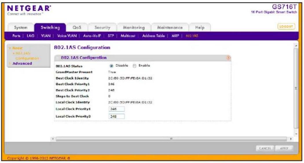
To configure the global 802.1AS settings on the switch:
- Enable or disable 802.1AS globally on the switch. The default mode is Enable.
- Configure the Priority1 value of the local clock (this time-aware bridge).
- Configure the Priority2 value of the local clock (this time-aware bridge).
- Click Cancel to cancel the configuration on the screen and reset the data on the screen to the latest value of the switch.
- If you make any changes to the page, click Apply to retain the changes to the system.
The following table shows the non-configurable information on the 802.1AS Configuration page.
| Field Description | |
| GrandMaster Present Identifies | whether Grand Master Clock is present. The default is False. |
| Best Clock Identity Shows the | Best Clock Identity detected by this time-aware bridge. |
| Best Clock Priority1 Shows the | Priority1 value of the best clock on the switch. |
| Best Clock Priority2 Shows the | Priority2 value of the best clock on the switch. |
| Steps to Best Clock Shows the | number of links in the path from the Best Clock to this time-aware bridge. If this time-aware bridge is the best, the value is zero. |
| Local Clock Identity Shows the | Clock Identity of this time-aware bridge. |
802.1AS Port Settings
Use the 802.1AS Port Settings page to configure and view per-port 802.1AS settings. To display the 802.1AS Port Settings page click the Switching tab, then click 802.1AS > Advanced > 802.1AS Port Settings.
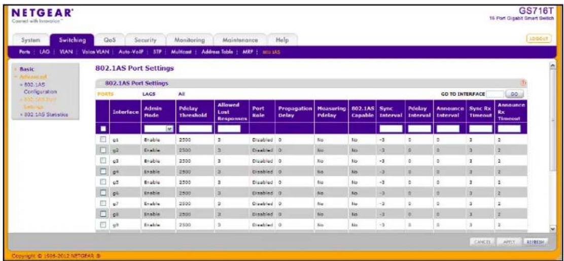
To configure the 802.1AS port settings:
- To configure 802.1AS settings for one or more ports, click PORTS. To configure 802.1AS settings for one or more LAGs, click LAGs. To configure 802.1AS settings for both ports and LAGs, click ALL.
- Select the check box next to the port or LAG to configure. You can select multiple ports or LAGs to apply the same settings to the selected interfaces. Select the check box in the heading row to apply the same settings to all interfaces.
- Enable or disable 802.1AS on the interface.
- Set the Pdelay threshold. This value specifies the propagation delay threshold on the interface. The threshold determines whether the port is capable of participating in the 802.1AS protocol. If the propagation delay on the interface is above the threshold you configure, the interface is not considered capable of participating in the 802.1AS protocol. The peer delay must be less than the threshold value configured on the interface. The default value is 2500 nanoseconds. The range is 0–1,000,000,000 ns.
-
Set the value for Allowed Lost Responses. If the interface does not receive valid responses to PDELAY_REQ messages above the value of the allowed lost responses, a port is considered to not be exchanging peer delay messages with its neighbor. The default value is 3. The range is 0–65535.
-
View the following non-configurable fields:
-
The Port Role specifies the 802.1AS role of the interface. The possible roles are as follows:
- Disabled (default)
Master - Slave
Passive
• The Propagation Delay field shows the mean propagation delay on the interface.
- The Measuring Pdelay field shows whether the interface is receiving PDELAY response messages from other end of the link.
- The 802.1AS Capable field shows whether the interface is 802.1AS capable or not. By default, the interface is not 802.1AS Capable.
- Configure the Sync Interval. This value is the logarithm to the base 2 of the mean-time interval between successive SYNC messages sent on this interface. The default value is -3. The range is -5 to 5.
- Configure the Pdelay Interval. This value is the logarithm to the base 2 of the mean time interval between successive PDELAY_REQ messages sent on this interface. The default value is 0. The range is -5 to 5.
- Configure the Announce Interval. This value is the logarithm to the base 2 of the mean time interval between successive ANNOUNCE messages sent on this interface. The default value is 0. The range is -5 to 5.
- Configure the SyncRx Timeout. This value sets the number of SYNC intervals that have to pass without receipt of SYNC information before considering that the master is no longer transmitting. The default value is 3. The range is 2 to 255.
- Configure the AnnounceRx Timeout. This value sets the number of ANNOUNCE intervals that have to pass without receipt of ANNOUNCE PDU before considering that the master is no longer transmitting. The default value is 2. The range is 2 to 255.
- Click Cancel to cancel the configuration on the screen and reset the data on the screen to the latest value of the switch.
- If you make any changes to the page, click Apply to retain the changes to the system.
- Click Refresh to reload the page and update it with the most current information.
802.1AS Statistics
The 802.1AS Statistics page displays information regarding the 802.1AS messages transmitted and received by each interface. To display the 802.1AS Statistics page click the Switching tab, then click 802.1AS > Advanced > 802.1AS Statistics.
If all 802.1AS statistics do not fit on the page, use the horizontal scroll bar to view additional settings. Together, the following two figures show all fields on the page.
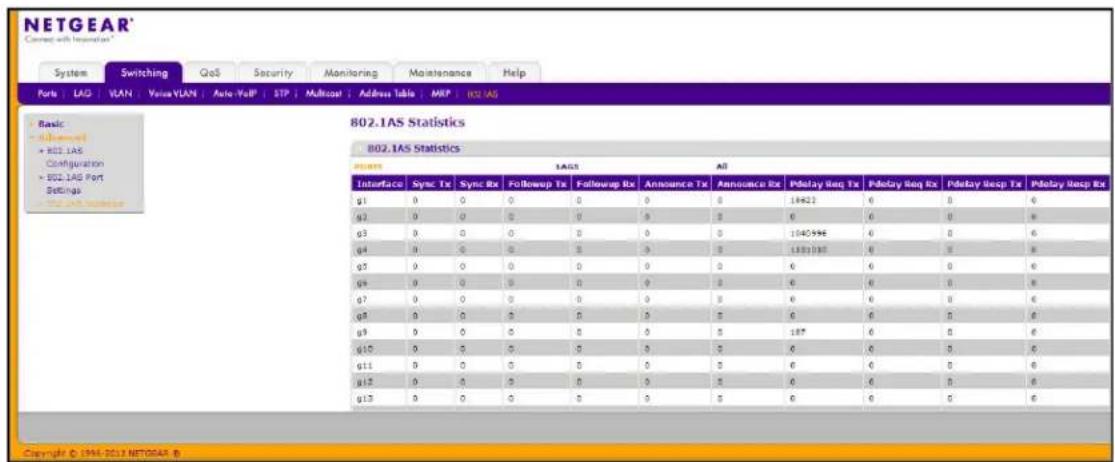
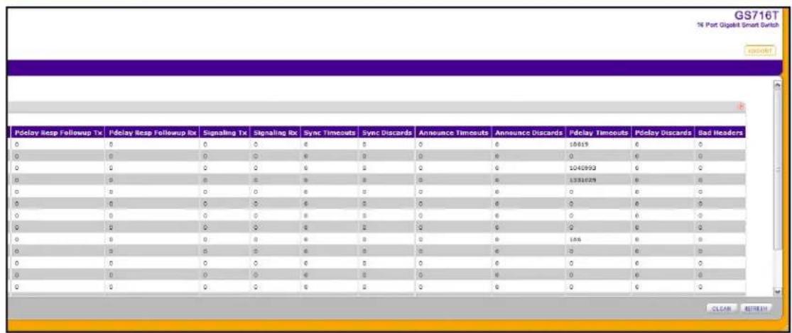
The following table describes the information the 802.1AS Statistics page displays.
| Field Description | |
| Interface Identifies the interface associated with the rest of the 802.1AS statistics in the row. | |
| Sync Tx Displays the total number of SYNC packets transmitted without error. | |
| Sync Rx Displays the total number of SYNC packets received without error. | |
| Field | Description |
| Followup Tx Displays the total | number of FOLLOWUP packets transmitted without error. |
| Followup Rx Displays the total | number of FOLLOWUP packets received without error. |
| Announce Tx Displays the total | number of ANNOUNCE packets transmitted without error. |
| Announce Rx Displays the total | number of ANNOUNCE packets received without error. |
| Pdelay Req Tx Displays the total | number of PDELAY_REQ packets transmitted without error. |
| Pdelay Req Rx Displays the total | number of PDELAY_REQ packets received without error. |
| Pdelay Resp Tx Displays the total | number of PDELAY_RESP packets transmitted without error. |
| Pdelay Resp Rx Displays the total | number of PDELAY_RESP packets received without error. |
| Pdelay Resp Followup Tx Displays the total number of PDELAY_RESP_FOLLOWUP packets transmitted without error. | |
| Pdelay Resp Followup Rx Displays the total number of PDELAY_RESP_FOLLOWUP packets received without error. | |
| Signaling Tx Displays the total number of SIGNALING packets transmitted without error. | |
| Signaling Rx Displays the total number of SIGNALING packets received without error. | |
| Sync Timeouts Displays the total number of SYNC receipt timeouts occurred. | |
| Sync Discards Displays the total number of SYNC packets discarded. | |
| Announce Timeouts Displays the total number of ANNOUNCE receipt timeouts occurred. | |
| Announce Discards Displays the total number of ANNOUNCE packets discarded. | |
| Pdelay Timeouts Displays the total number of PDELAY receipt timeouts occurred. | |
| Pdelay Discards | Displays the total number of PDELAY packets discarded. |
| Bad Headers | Displays the total number of packets received with bad header. |
To reload the page, click Refresh. To reset the statistics for all interfaces, click Clear.
Use the features in the QoS tab to configure Quality of Service (QoS) settings on the switch. The QoS tab contains links to the following features:
• Class of Service on page 151
• Differentiated Services on page 159
In a typical switch, each physical port consists of one or more queues for transmitting packets on the attached network. Multiple queues per port are often provided to give preference to certain packets over others based on user-defined criteria. When a packet is queued for transmission in a port, the rate at which it is serviced depends on how the queue is configured and possibly the amount of traffic present in the other queues of the port. If a delay is necessary, packets get held in the queue until the scheduler authorizes the queue for transmission. As queues become full, packets have no place to be held for transmission and get dropped by the switch.
QoS is a means of providing consistent, predictable data delivery by distinguishing between packets that have strict timing requirements from those that are more tolerant of delay. Packets with strict timing requirements are given special treatment in a QoS-capable network. With this in mind, all elements of the network must be QoS-capable. The presence of at least one node which is not QoS-capable creates a deficiency in the network path and the performance of the entire packet flow is compromised.
Class of Service
The Class of Service (CoS) queueing feature lets you directly configure certain aspects of switch queueing. This provides the desired QoS behavior for different types of network traffic when the complexities of DiffServ are not required. The priority of a packet arriving at an interface can be used to steer the packet to the appropriate outbound CoS queue through a mapping table. CoS queue characteristics that affect queue mapping, such as minimum guaranteed bandwidth, or transmission rate shaping are user-configurable at the queue (or port) level.
Eight queues per port are supported.
From the Class of Service link under the QoS tab, you can access the following pages:
• Basic CoS Configuration on page 152
• CoS Interface Configuration on page 153
• Interface Queue Configuration on page 155
• 802.1p to Queue Mapping on page 156
• DSCP to Queue Mapping on page 158
Basic CoS Configuration
Use the Trust Mode Configuration page to set the class of service trust mode of an interface. Each port in the switch can be configured to trust one of the packet fields (802.1p or IP DSCP), or to not trust any packet's priority designation (untrusted mode). If the port is set to a trusted mode, it uses a mapping table appropriate for the trusted field being used. This mapping table indicates the CoS queue to which the packet should be forwarded on the appropriate egress port(s). Of course, the trusted field must exist in the packet for the mapping table to be of any use, so there are default actions performed when this is not the case. These actions involve directing the packet to a specific CoS level configured for the ingress port as a whole, based on the existing port default priority as mapped to a traffic class by the current 802.1p mapping table.
Alternatively, when a port is configured as untrusted, it does not trust any incoming packet priority designation and uses the port default priority value instead. All packets arriving at the ingress of an untrusted port are directed to a specific CoS queue on the appropriate egress port(s), in accordance with the configured default priority of the ingress port. This process is also used for cases where a trusted port mapping is unable to be honored, such as when a non-IP packet arrives at a port configured to trust the IP DSCP value.
To display the Basic CoS Configuration page, click QoS > Basic > CoS Configuration.
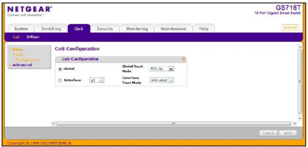
To configure global CoS settings:
- Select the Global radio button to configure the trust mode settings that apply to all interfaces.
Alternatively, you can select the Interface radio button to apply trust mode settings to individual interfaces. The per-interface setting overrides the global settings.
-
Select the trust mode for all interfaces (Global Trust Mode) or the selected interface (Interface Trust Mode). This setting determines the type of CoS marking to trust when the frame enters the port.
-
Untrusted. Do not trust any CoS packet marking at ingress.
- 802.1p. The eight priority tags that are specified in IEEE 802.1p are p0 to p7. The QoS setting lets you map each of the eight priority levels to one of eight internal hardware priority queues.
-
DSCP. The six most significant bits of the DiffServ field are called the Differentiated Services Code Point (DSCP) bits.
-
Click Cancel to cancel the configuration on the screen and reset the data on the screen to the latest value of the switch.
-
If you change any of the settings on the page, click Apply to send the updated configuration to the switch.
CoS Interface Configuration
Use the CoS Interface Configuration page to apply an interface shaping rate to all interfaces or to a specific interface.
To display the CoS Interface Configuration page, click the QoS > CoS tab, and then click the Advanced > CoS Interface Configuration link.
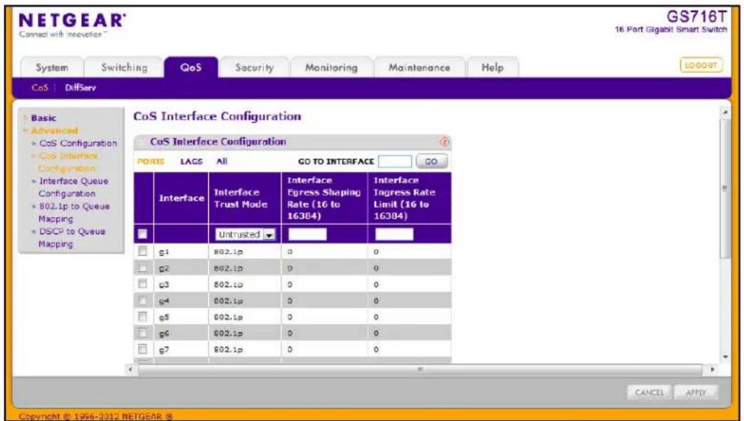
To configure CoS settings for an interface:
- To configure CoS settings for a physical port, click PORTS.
- To configure CoS settings for a Link Aggregation Group (LAG), click LAGS.
- To configure CoS settings for both physical ports and LAGs, click ALL.
- Select the check box next to the port or LAG to configure. You can select multiple ports and LAGs to apply the same setting to the selected interfaces.
- From the Interface Trust Mode field, specify whether or not the selected interface(s) trust a particular packet marking when the packet enters the port.
- Untrusted. Do not trust any CoS packet marking at ingress.
- 802.1p. The eight priority tags that are specified in IEEE 802.1p are p0 to p7. The QoS setting lets you map each of the eight priority levels to one of eight internal hardware priority queues.
-
DSCP. The six most significant bits of the DiffServ field are called the Differentiated Services Code Point (DSCP) bits.
-
From the Interface Shaping Rate field, specify the maximum bandwidth allowed on the selected interface(s). This setting is typically used to shape the outbound transmission rate in increments of 64 kbps. This value is controlled independently of any per-queue maximum bandwidth configuration. It is effectively a second-level shaping mechanism. The default value is 0, in increments of 16. A value of 0 means the maximum is unlimited.
The expected shaping at egress interface is calculated as:
(frameSize × shaping × 64) ÷ (frameSize + IFG), where IFG (Inter frame gap) is 20 bytes, frameSize is the configured frame size of the traffic, and shaping is the configured traffic shaping in the Interface Shaping Rate field.
For example, when a 64 byte frame size and 64 kbps interface shaping rate are configured, the expected shaping will be approximately 3121 kbps.
- Click Cancel to cancel the configuration on the screen and reset the data on the screen to the latest value of the switch.
- If you make changes to the page, click Apply to apply the changes to the system.
Interface Queue Configuration
Use the Interface Queue Configuration page to define what a particular queue does by configuring switch egress queues. User-configurable parameters control the amount of bandwidth used by the queue, the queue depth during times of congestion, and the scheduling of packet transmission from the set of all queues on a port. Each port has its own CoS queue-related configuration.
The configuration process is simplified by allowing each CoS queue parameter to be configured globally or per-port. A global configuration change is automatically applied to all ports in the system.
To display the Interface Queue Configuration page, click the QoS > CoS tab, and then click the Advanced > Interface Queue Configuration link.
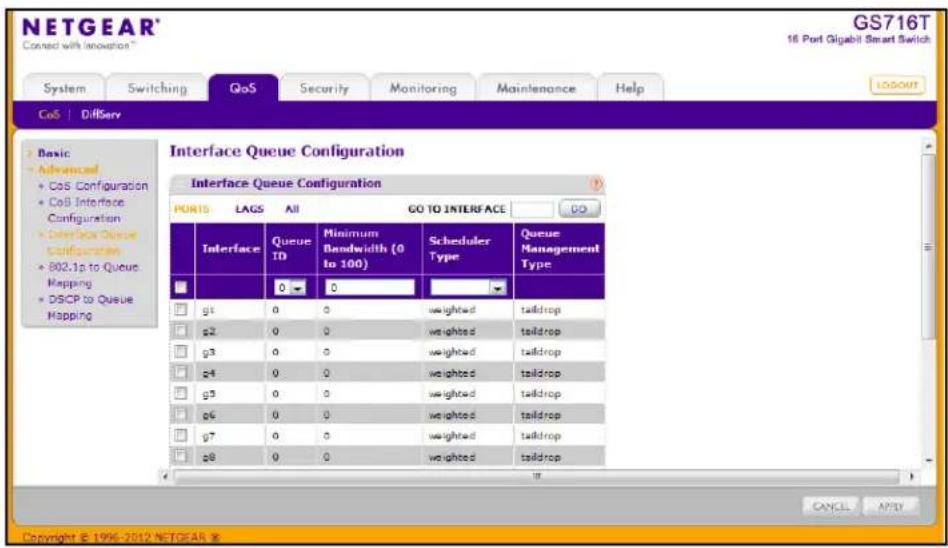
To configure CoS queue settings for an interface:
-
To configure CoS queue settings for a physical port, click PORTS.
-
To configure CoS queue settings for a Link Aggregation Group (LAG), click LAGS.
-
To configure CoS queue settings for both physical ports and LAGs, click ALL.
-
Select the check box next to the port or LAG to configure. You can select multiple ports and LAGs to apply the same setting to the selected interfaces. Select the check box in the heading row to apply a trust mode or rate to all interfaces.
-
Configure any of the following settings:
- Queue ID. Use the menu to select the queue to be configured.
- Minimum Bandwidth. Enter a percentage of the maximum negotiated bandwidth for the selected queue on the interface. Specify a percentage from 0–100, in increments of 1.
- Scheduler Type. Selects the type of queue processing from the drop down menu. Options are Weighted and Strict. Defining on a per-queue basis allows the user to create the desired service characteristics for different types of traffic.
- Weighted: Weighted round robin associates a weight to each queue. This is the default.
- Strict: Services traffic with the highest priority on a queue first.
- Queue Management Type. Displays the type of packet management used for all packets, which is Taildrop. All packets on a queue are safe until congestion occurs. At this point, any additional packets queued are dropped.
-
Click Cancel to cancel the configuration on the screen and reset the data on the screen to the latest value of the switch.
-
If you make changes to the page, click Apply to apply the changes to the system.
802.1p to Queue Mapping
The 802.1p to Queue Mapping page also displays the Current 802.1p Priority Mapping table. To display the 801.p to Queue Mapping page, click QoS > CoS > Advanced > 802.1p to Queue Mapping.
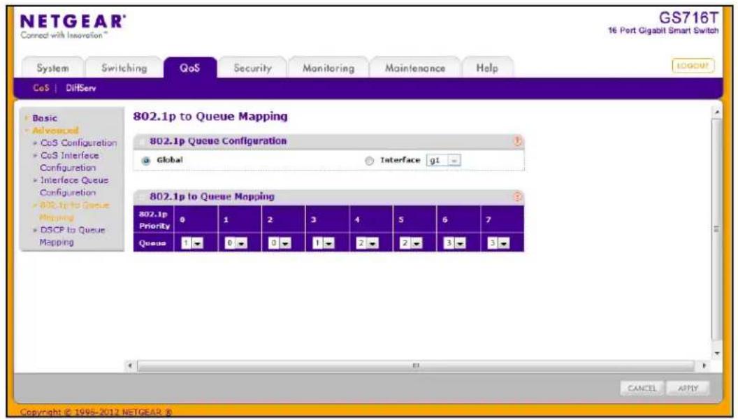
To map 802.1p priorities to queues:
- Select the Global radio button to apply the same 802.1p priority mapping to all CoS configurable interfaces or select the Interface radio button to apply 802.1p priority mapping to on a per-interface basis.
If you map 802.1p priorities to individual interfaces, select the Interface radio button and then select the interface from the drop-down menu. The interface settings override the global settings for 802.1p priority mapping.
- Select the queue to map to the predefined 802.1p priority values.
The 802.1p Priority row contains traffic class selectors for each of the eight 802.1p priorities to be mapped. The priority goes from low (0) to high (7). For example, traffic with a priority of 0 is for most data traffic and is sent using “best effort.” Traffic with a higher priority, such as 7, might be time-sensitive traffic, such as voice or video.
The values in each drop down menu represent the traffic class. The traffic class is the hardware queue for a port. Higher traffic class values indicate a higher queue position. Before traffic in a lower queue is sent, it must wait for traffic in higher queues to be sent.
-
Click Cancel to cancel the configuration on the screen and reset the data on the screen to the latest value of the switch.
-
If you make changes to the page, click Apply to apply the changes to the system.
DSCP to Queue Mapping
Use the DSCP to Queue Mapping page to specify which internal traffic class to map the corresponding DSCP value.
To display the IP DSCP Mapping page, click QoS > CoS > Advanced > DSCP to Queue Mapping.
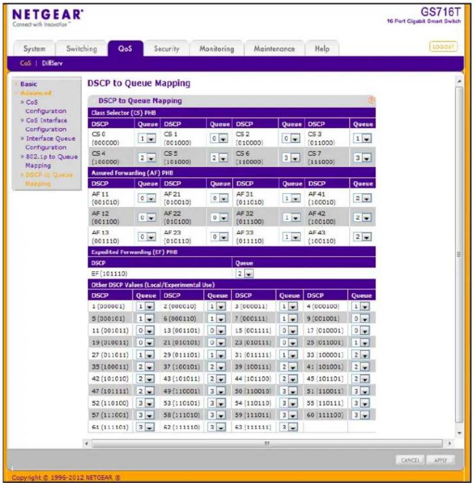
To map DSCP values to queues:
- For each DSCP value, select a hardware queue to associate with the value.
The traffic class is the hardware queue for a port. Higher traffic class values indicate a higher queue position. Before traffic in a lower queue is sent, it must wait for traffic in higher queues to be sent. Valid range is 0–7.
- Click Cancel to cancel the configuration on the screen and reset the data on the screen to the latest value of the switch.
- If you make changes to the page, click Apply to apply the changes to the system.
Differentiated Services
The QoS feature contains Differentiated Services (DiffServ) support that allows traffic to be classified into streams and given certain QoS treatment in accordance with defined per-hop behaviors.
Standard IP-based networks are designed to provide “best effort” data delivery service. “Best effort” service implies that the network delivers the data in a timely fashion, although there is no guarantee that it will. During times of congestion, packets may be delayed, sent sporadically, or dropped. For typical Internet applications, such as e-mail and file transfer, a slight degradation in service is acceptable and in many cases unnoticeable. Conversely, any degradation of service has undesirable effects on applications with strict timing requirements, such as voice or multimedia.
Defining DiffServ
To use DiffServ for QoS, the Web pages accessible from the Differentiated Services menu page must first be used to define the following categories and their criteria:
- Class: Create classes and define class criteria.
- Policy: Create policies, associate classes with policies, and define policy statements.
- Service: Add a policy to an inbound interface
Packets are classified and processed based on defined criteria. The classification criteria is defined by a class. The processing is defined by a policy's attributes. Policy attributes may be defined on a per-class instance basis, and it is these attributes that are applied when a match occurs. A policy can contain multiples classes. When the policy is active, the actions taken depend on which class matches the packet.
Packet processing begins by testing the class match criteria for a packet. A policy is applied to a packet when a class match within that policy is found.
The Differentiated Services menu page contains links to the various DiffServ configuration and display features.
To display the page, click QoS > DiffServ. The Differentiated Services menu page contains links to the following features:
- DiffServ Configuration
- Class Configuration
- IPv6 Class Configuration
• Policy Configuration
• Service Configuration
• Service Statistics
DiffServ Configuration
Use the DiffServ Configuration page to display DiffServ General Status Group information, which includes the current administrative mode setting as well as the current and maximum number of rows in each of the main DiffServ private MIB tables.
To display the page, click QoS > DiffServ > Advanced > DiffServ Configuration.
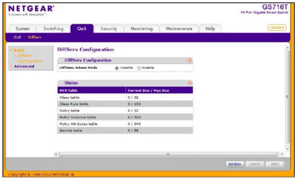
To configure the global DiffServ mode:
-
Select the administrative mode for DiffServ:
-
Enable. Differentiated Services are active.
-
Disable. The DiffServ configuration is retained and can be changed, but it is not active.
-
Click Cancel to cancel the configuration on the screen and reset the data on the screen to the latest value of the switch.
-
If you make changes to the page, click Apply to apply the changes to the system.
The following table describes the information displayed in the Status table on the DiffServ Configuration page:
| Field Description | |
| Class Table Displays the current and maximum number of rows of the class table. | |
| Class Rule Table Displays the current and maximum number of rows of the class rule table. | |
| Policy Table Displays the current and maximum number of rows of the policy table. | |
| Policy Instance Table | Displays the current and maximum number of rows of the policy instance table. |
| Policy Attributes Table | Displays the current and maximum number of rows of the policy attributes table. |
| Service Table | Displays the current and maximum number of rows of the service table. |
Class Configuration
Use the Class Configuration page to add a new DiffServ class name, or to rename or delete an existing class. The page also allows you to define the criteria to associate with a DiffServ class. As packets are received, these DiffServ classes are used to prioritize packets. You can have multiple match criteria in a class. The logic is a Boolean logical-and for this criteria. After creating a Class, click the class link to the Class page.
To display the page, click QoS > DiffServ > Advanced > Class Configuration.
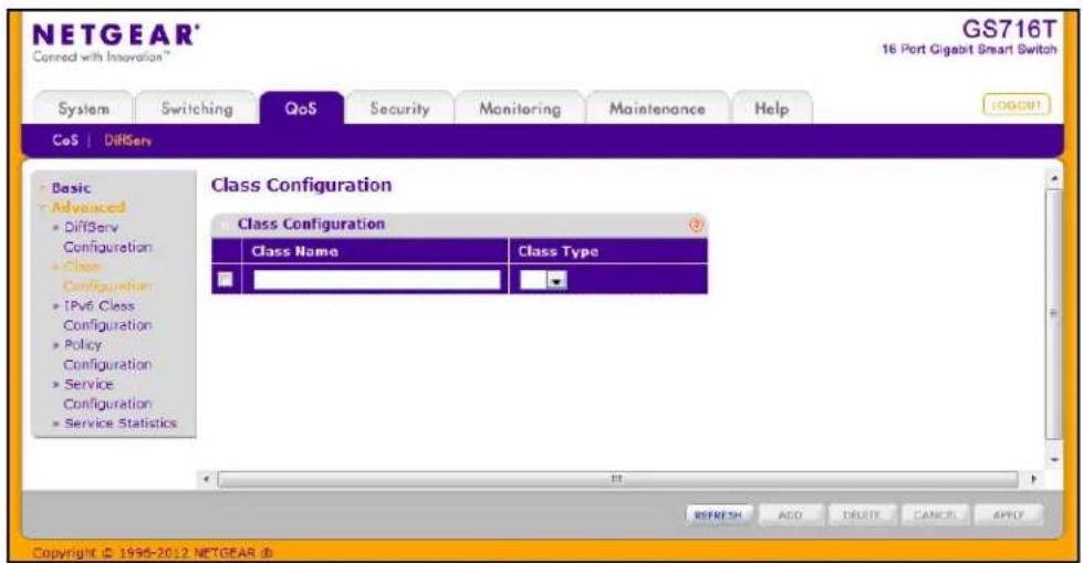
To configure a DiffServ class:
- To create a new class, enter a class name, select the class type, and click Add.
The switch supports only the Class Type value All, which means all the various match criteria defined for the class should be satisfied for a packet match. All signifies the logical AND of all the match criteria. - To rename an existing class, select the check box next to the configured class, update the name, and click Apply.
- To remove a class, click the check box beside the Class Name, then click Delete.
- Click Refresh to refresh the page with the most current data from the switch.
- Click Cancel to cancel the configuration on the screen and reset the data on the screen to the latest value of the switch. After creating a Class, click the class link to the Class page.
To configure the class match criteria:
- Click the class name for an existing class.
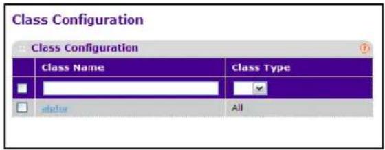
The class name is a hyperlink. The following figure shows the configuration fields for the class.
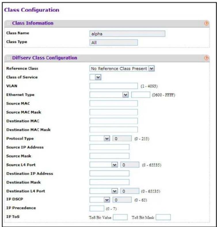
- Define the criteria to associate with a DiffServ class:
• Reference Class. Selects a class to start referencing for criteria. A specified class can reference at most one other class of the same type.
- Class of Service. Select the field and enter a class of service 802.1p user priority value to be matched for the packets. The valid range is 0–7.
- VLAN. Select the field and enter a VLAN ID to be matched for packets. The VLAN ID range is 1–4093.
- Ethernet Type. Select an EtherType keyword or enter an EtherType value to add a match condition based on the EtherType value.
- Source MAC. Requires a packet's source MAC address to match the address specified here.
- Source MAC Mask. Indicates which bits in the source MAC address are significant and which are ignored. An F indicates that the bit is significant, while a 0 indicates that the bit is ignored. For example, a MAC mask of FF:FF:FF:FF:FF indicates that all bits in the source MAC address are used as match criteria.
- Destination MAC. Requires a packet's destination MAC address to match the address specified here.
- Destination MAC Mask. Indicates which bits in the destination MAC address are significant and which are ignored. An F indicates that the bit is significant, while a 0 indicates that the bit is ignored. For example, a MAC mask of FF:FF:FF:FF:FF:FF indicates that all bits in the destination MAC address are used as match criteria.
- Protocol Type. Select a layer 4 protocol to use for the match criteria in the packet or select Other and enter the value to match in the Protocol field of the IP packet.
- Source IP Address. Requires a packet's source port IP address to match the address listed here. In the IP Address field, enter a valid source IP address in dotted decimal format.
- Source Mask. Enter a valid subnet mask to determine which bits in the IP address are significant. Note that this is not a wildcard mask.
- Source L4 Port. Requires a packet's TCP/UDP source port to match the port you select. Select the desired L4 keyword from the list on which the rule can be based. If you select Other, the screen refreshes and a Port ID field appears. Enter a user-defined Port ID by which packets are matched to the rule.
- Destination IP Address. Requires a packet's destination port IP address to match the address listed here. In the IP Address field, enter a valid destination IP address in dotted decimal format.
- Destination Mask. Enter a valid subnet mask to determine which bits in the IP address are significant. This is not a wildcard mask.
- Destination L4 Port. Requires a packet's TCP/UDP destination port to match the port you select. Select the desired L4 keyword from the list on which the rule can be based. If you select Other, the screen refreshes and a Port ID field appears. Enter a user-defined Port ID by which packets are matched to the rule.
- IP DSCP. Matches the packet's DSCP to the class criteria's when selected. Select the DSCP type from the menu or enter a DSCP value to match. If you select Other, enter a custom value in the DSCP Value field that appears.
- IP Precedence. Matches the packet's IP Precedence value to the class criteria's when Enter a value in the range of 0–7.
-
IP ToS. Matches the packet's Type of Service bits in the IP header to the class criteria's when selected and a value is entered. In the ToS Bits field, enter a two-digit hexadecimal number to match the bits in a packet's ToS field. In the ToS Mask field, specify the bit positions that are used for comparison against the IP ToS field in a packet.
-
Click Cancel to cancel the configuration on the screen and reset the data on the screen to the latest value of the switch.
- If you change any of the settings on the page, click Apply to send the updated configuration to the switch. Configuration changes occur immediately.
- Click Refresh to refresh the page with the most current data from the switch.
IPv6 Class Configuration
Use the IPv6 Class Configuration page to add a new IPv6 DiffServ class name, or to rename or delete an existing class. The page also allows you to define the criteria to associate with a DiffServ class. As packets are received, these DiffServ classes are used to prioritize packets. You can have multiple match criteria in a class. The logic is a Boolean logical-and for this criteria. After creating a Class, click the class link to the Class page.
To display the page, click QoS > DiffServ > Advanced > IPv6 Class Configuration.
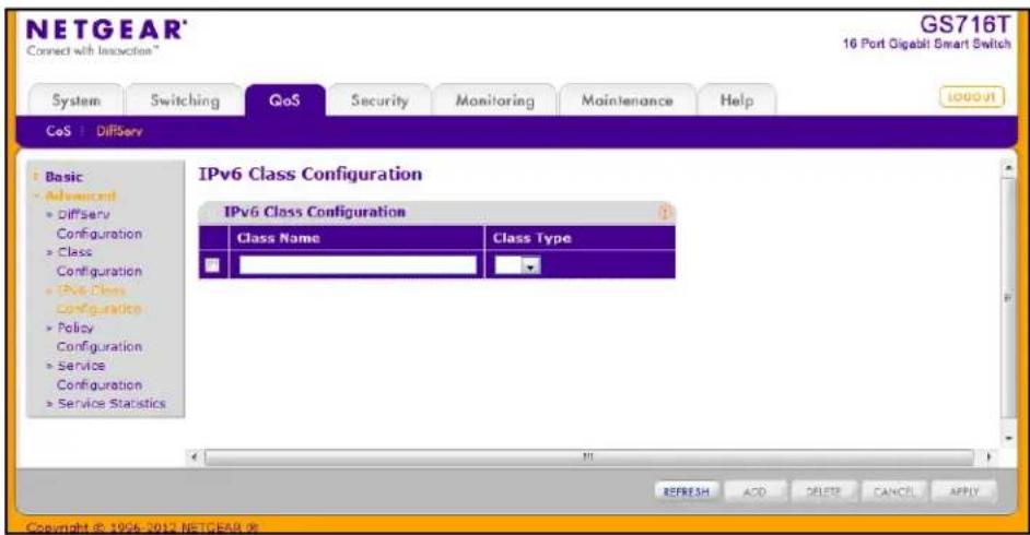
To configure a DiffServ class:
- To create a new class, enter a class name, select the class type, and click ADD. This field also lists all the existing DiffServ class names, from which one can be selected.
The switch supports only the Class Type value All, which means all the various match criteria defined for the class should be satisfied for a packet match. All signifies the logical AND of all the match criteria. Only when a new class is created, this field is a selector field. After class creation this becomes a non-configurable field displaying the configured class type.
-
To rename an existing class, select the check box next to the configured class, update the name, and click APPLY.
-
To remove a class, click the check box beside the Class Name, then click DELETE.
-
Click REFRESH to refresh the page with the most current data from the switch.
-
Click CANCEL to cancel the configuration on the screen and reset the data on the screen to the latest value of the switch. After creating a Class, click the class link to the Class page.
To configure the class match criteria:
- Click the class name for an existing class.
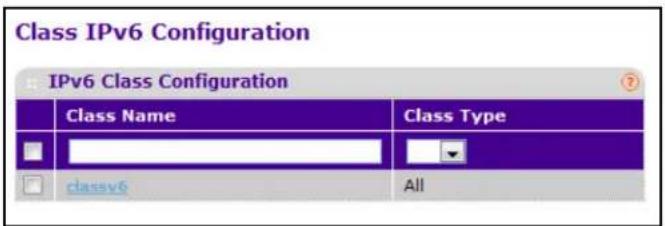
The class name is a hyperlink. The following figure shows the configuration fields for the class.
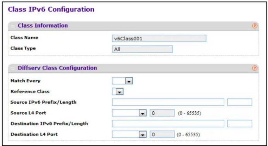
-
Class Name - Displays the name for the configured DiffServ class.
-
Class Type - Displays the DiffServ class type. Options:
• All
Only when a new class is created, this field is a selector field. After class creation this becomes a non-configurable field displaying the configured class type.
-
Define the criteria to associate with a DiffServ class:
-
Match Every - This adds to the specified class definition a match condition whereby all packets are considered to belong to the class.
- Reference Class - This lists the class(es) that can be assigned as reference class(es) to the current class.
-
Source IPv6 Prefix/Length - This is a valid Source IPv6 Prefix to compare against an IPv6 Packet. Prefix is always specified with the Prefix Length. Prefix can be entered in the range of ::0 to FFFF:FFFF:FFFF:FFFF:FFFF:FFFF:FFFF and Prefix Length can be entered in the range of 0 to 128.
-
Source L4 Port - This lists the keywords for the known source layer 4 ports from which one can be selected. The list includes 'other' as an option for the unnamed ports.
- Destination IPv6 Prefix/Length - This is a valid Destination IPv6 Prefix to compare against an IPv6 Packet. Prefix is always specified with the Prefix Length. Prefix can be entered in the range of ::0 to FFFF:FFFF:FFFF:FFFF:FFFF:FFFF:FFFF and Prefix Length can be entered in the range of 0 to 128.
-
Destination L4 Port - This lists the keywords for the known destination layer 4 ports from which one can be selected. The list includes 'other' as an option for the unnamed ports.
-
Click CANCEL to cancel the configuration on the screen. Resets the data on the screen to the latest value of the switch.
-
Click APPLY to send the updated configuration to the switch. Configuration changes take effect immediately.
Policy Configuration
Use the Policy Configuration page to associate a collection of classes with one or more policy statements. After creating a Policy, click the policy link to the Policy page.
To display the page, click QoS > DiffServ > Advanced > Policy Configuration.
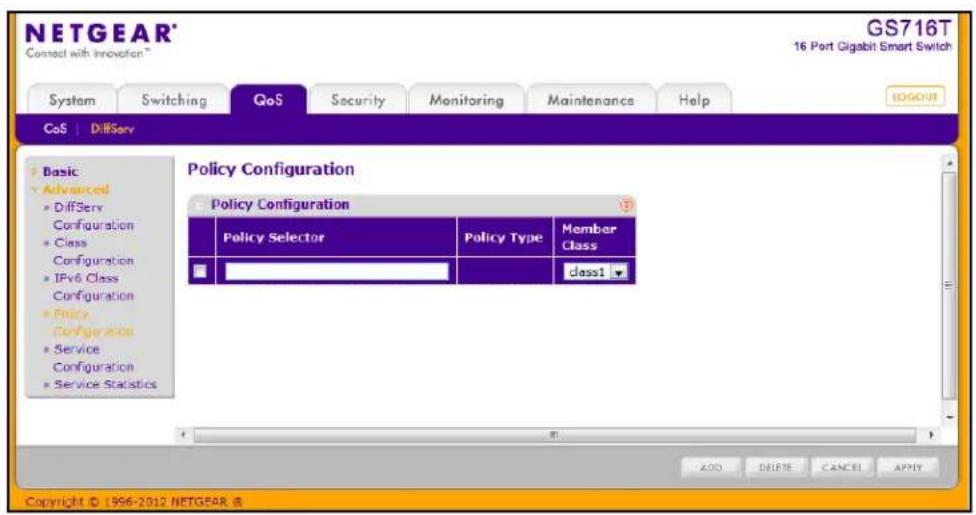
To configure a DiffServ policy:
- To create a new policy, enter a policy name in the Policy Selector field, select the existing DiffServ class to associate with the policy, and click Add.
The available policy type is In, which indicates the type is specific to inbound traffic. This field is not configurable. - To rename an existing policy or add a new member class to the policy, select the check box next to the configured class, update the fields, and click Apply.
- To remove a policy, click the check box beside the policy, then click Delete.
- Click Refresh to refresh the page with the most current data from the switch.
- Click Cancel to cancel the configuration on the screen and reset the data on the screen to the latest value of the switch. After creating a Class, click the class link to the Class page.
To configure the policy attributes:
- Click the name of the policy.
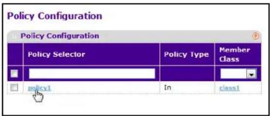
The policy name is a hyperlink. The following figure shows the configuration fields for the policy.
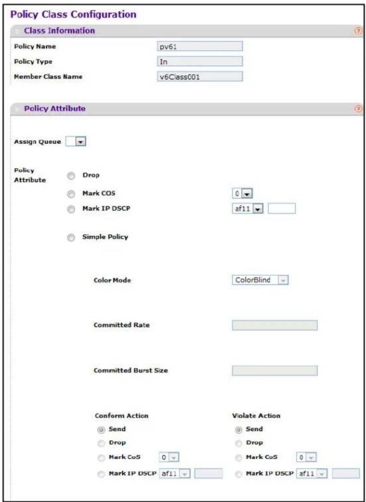
-
Select the queue to which packets will of this policy-class will be assigned.
-
Configure the policy attributes:.
- Drop. Select this option to drop packets for this policy-class.
- Mark CoS. Enter the specified Class of Service queue number to mark all packets for the associated traffic stream with the specified class of service value in the priority field of the 802.1p header. If the packet does not already contain this header, one is inserted. The CoS value is an integer from 0–7.
- Mark IP DSCP. Use this attribute to mark all packets for the associated traffic stream with IP DSCP value you choose from the menu. If you select Other, enter a custom value in the DSCP Value field that appears.
-
Simple Policy. Use this attribute to establish the traffic policing style for the specified class. The simple form of the policy command uses a single data rate and burst size, resulting in two outcomes: confirm and violate.
-
If you select the Simple Policy attribute, you can configure the following fields:
• Color Mode. Color Blind is the supported color mode.
- Committed Rate. The committed rate is specified in kilobits-per-second (Kbps) and is an integer from 1–4294967295.
- Committed Burst Size. The committed burst size is specified in kilobytes (KB) and is an integer from 1–128.
- Conform Action. Determines what happens to packets that are considered conforming (below the police rate). Select one of the following actions:
- Send. (default) These packets are presented unmodified by DiffServ to the system forwarding element.
- Drop. These packets are immediately dropped.
- Mark CoS. These packets are marked by DiffServ with the specified CoS value before being presented to the system forwarding element. This selection requires that the Mark CoS value field be set.
- Mark IP DSCP. These packets are marked by DiffServ with the specified DSCP value before being presented to the system forwarding element. This selection requires that the DSCP value field be set. If you select Other, enter a custom value in the DSCP Value field that appears.
- Violate Action. Determines what happens to packets that are considered non-conforming (above the police rate). Select one of the following actions:
- Send. (default) These packets are presented unmodified by DiffServ to the system forwarding element.
- Drop. (default) These packets are immediately dropped.
- Mark CoS. These packets are marked by DiffServ with the specified CoS value before being presented to the system forwarding element. This selection requires that the Mark CoS value field be set.
-
Mark IP DSCP. These packets are marked by DiffServ with the specified DSCP value before being presented to the system forwarding element. This selection requires that the DSCP value field be set. If you select Other, enter a custom value in the DSCP Value field that appears.
-
Click Cancel to cancel the configuration on the screen and reset the data on the screen to the latest value of the switch.
- If you change any of the settings on the page, click Apply to send the updated configuration to the switch. Configuration changes take effect immediately.
- Click Refresh to refresh the page with the most current data from the switch.
Service Configuration
Use the Service Configuration page to activate a policy on an interface.
To display the page, click QoS > DiffServ > Advanced > Service Configuration.
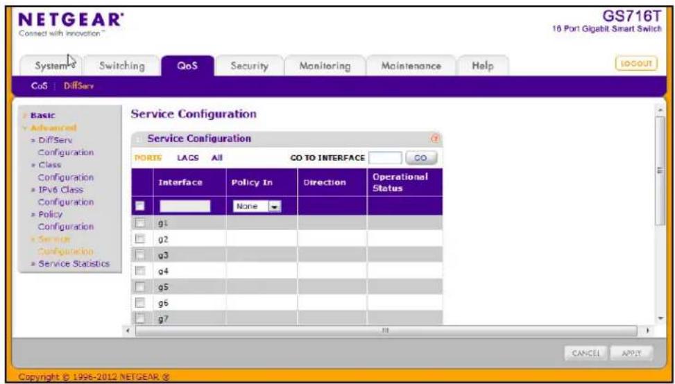
To configure DiffServ policy settings on an interface:
- To configure DiffServ policy settings for a physical port, click PORTS.
- To configure DiffServ policy settings for a Link Aggregation Group (LAG), click LAGS.
- To configure DiffServ policy settings for both physical ports and LAGs, click ALL.
- Select the check box next to the port or LAG to configure. You can select multiple ports and LAGs to apply the same setting to the selected interfaces. Select the check box in the heading row to apply the same settings to all interfaces.
- To activate a policy for the selected interface(s) select the policy from the Policy In menu, and then click Apply.
- To remove a policy from the selected interface(s) select None from the Policy In menu, and then click Apply.
- Click Cancel to cancel the configuration on the screen and reset the data on the screen to the latest value of the switch.
Service Statistics
Use the Service Statistics page to display service-level statistical information about all interfaces that have DiffServ policies attached.
To display the page, click the QoS > DiffServ tab and then click the Advanced > Service Statistics link.
The following table describes the information available on the Service Statistics page.
| Field Description | |
| Interface Displays the interface for which service statistics are to display. | |
| Direction | Displays the direction of packets for which service statistics display, which is always In. |
| Policy Name Displays the policy associated with the selected interface. | |
| Operational Status | Displays the operational status of this service interface, which is either Up or Down. |
| Discarded Packets | Displays the total number of packets discarded for all class instances in this service policy for any reason due to DiffServ treatment. This is the overall count per-interface, per-direction. |
| Member Classes Selects the member class for which octet statistics are to display. | |
Click Refresh to update the page with the most current information.
Use the features available from the Security tab to configure management security settings for port, user, and server security. The Security tab contains links to the following features:
• Management Security Settings on page 173
- Configuring Management Access on page 185
• Port Authentication on page 193
• Traffic Control on page 200
- Configuring Access Control Lists on page 209
Management Security Settings
From the Management Security Settings page, you can configure the login password, Remote Authorization Dial-In User Service (RADIUS) settings, Terminal Access Controller Access Control System (TACACS+) settings, and authentication lists.
To display the page, click the Security > Management Security tab. The Management Security folder contains links to the following features:
- Change Password on page 174
• RADIUS Configuration on page 175 - Configuring TACACS+ on page 181
- Authentication List Configuration on page 184
Change Password
Use the page to change the login password. To display the page, click Security > Management Security > User Configuration > Change Password.
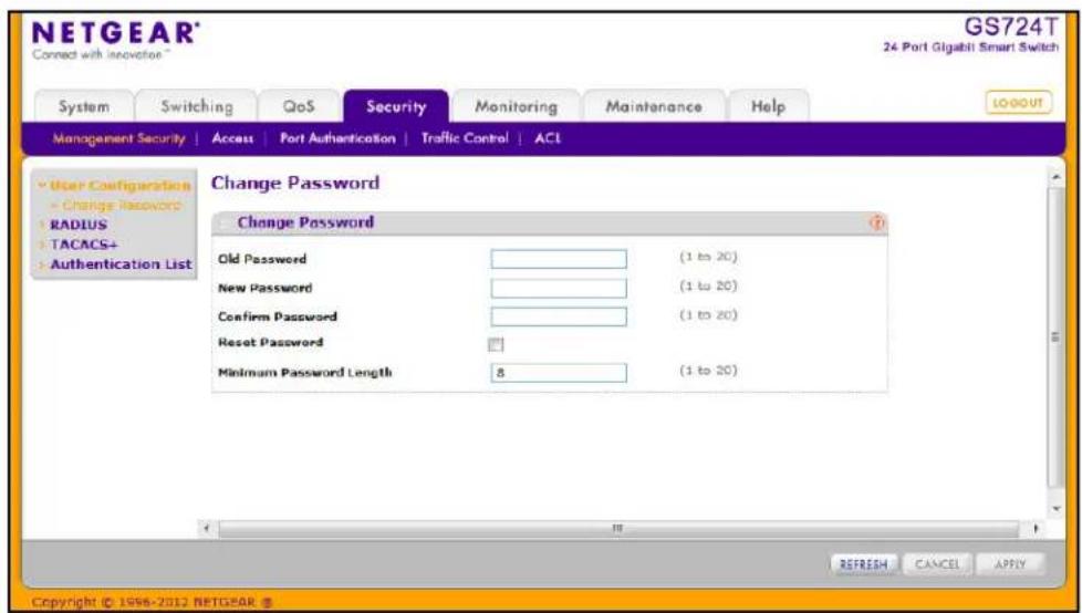
To change the login password for the management interface:
- Specify the current password in the Old Password field. The entered password will be displayed in asterisks (*). Passwords are 1–20 alphanumeric characters in length and are case sensitive.
- In the New Password field, enter the new password. It will not display as it is typed, and only asterisks (*) will show on the screen. Passwords are 1–20 alphanumeric characters in length and are case sensitive.
- To confirm the password, enter it again in the Confirm Password field to make sure you entered it correctly. This field will not display, but will show asterisks (*)
- Use the Reset Password field to reset the password to the default value.
- In the Minimum Password Length field, specify the minimum number of characters required for a valid password.
- Click Cancel to cancel the configuration on the screen and reset the data on the screen to the latest value of the switch.
- If you make changes to the page, click Apply to apply the changes to the system.
- Click Refresh to update the screen with the current information.
Note: In the case of a lost password, press the Factory Default Reset button on the front panel for more than one second to restore the factory default. The reset button will only reboot the device.
RADIUS Configuration
RADIUS servers provide additional security for networks. The RADIUS server maintains a user database, which contains per-user authentication information. The switch passes information to the configured RADIUS server, which can authenticate a user name and password before authorizing use of the network. RADIUS servers provide a centralized authentication method for:
- Web Access
- Access Control Port (802.1X)
The RADIUS folder contains links to the following features:
• Global Configuration on page 175
• RADIUS Server Configuration on page 177
• Accounting Server Configuration on page 179
Global Configuration
Use the RADIUS Configuration page to add information about one or more RADIUS servers on the network.
To access the RADIUS Configuration page, click Security > Management Security > RADIUS > Global Configuration.
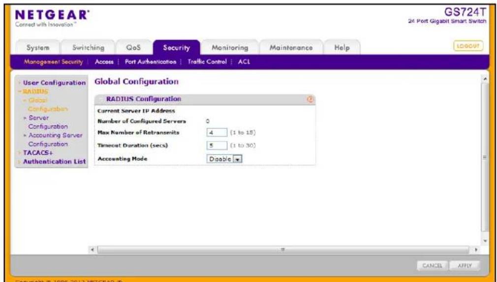
The Current Server IP Address field is blank if no servers are configured (see RADIUS Server Configuration on page 177). The switch supports up to three configured RADIUS servers. If more than one RADIUS servers are configured, the current server is the server configured as the primary server. If no servers are configured as the primary server, the current server is the most recently added RADIUS server.
To configure global RADIUS server settings:
- In the Max Number of Retransmits field, specify the value of the maximum number of times a request packet is retransmitted to the RADIUS server.
Consideration to maximum delay time should be given when configuring RADIUS max retransmit and RADIUS timeout. If multiple RADIUS servers are configured, the max retransmit value on each will be exhausted before the next server is attempted. A retransmit will not occur until the configured timeout value on that server has passed without a response from the RADIUS server. Therefore, the maximum delay in receiving a response from the RADIUS application equals the sum of (retransmit times timeout) for all configured servers. If the RADIUS request was generated by a user login attempt, all user interfaces will be blocked until the RADIUS application returns a response.
- In the Timeout Duration field, specify the timeout value, in seconds, for request retransmissions.
Consideration to maximum delay time should be given when configuring RADIUS max retransmit and RADIUS timeout. If multiple RADIUS servers are configured, the max retransmit value on each will be exhausted before the next server is attempted. A retransmit will not occur until the configured timeout value on that server has passed without a response from the RADIUS server. Therefore, the maximum delay in receiving a response from the RADIUS application equals the sum of (retransmit times timeout) for all configured servers. If the RADIUS request was generated by a user login attempt, all user interfaces will be blocked until the RADIUS application returns a response.
- From the Accounting Mode menu, select whether the RADIUS accounting mode is enabled or disabled on the current server.
- Click Cancel to cancel the configuration on the screen and reset the data on the screen to the latest value of the switch.
- If you make changes to the page, click Apply to apply the changes to the system.
RADIUS Server Configuration
Use the RADIUS Server Configuration page to view and configure various settings for the current RADIUS server configured on the system.
To access the RADIUS Server Configuration page, click Security > Management Security, and then click the RADIUS > Server Configuration link.
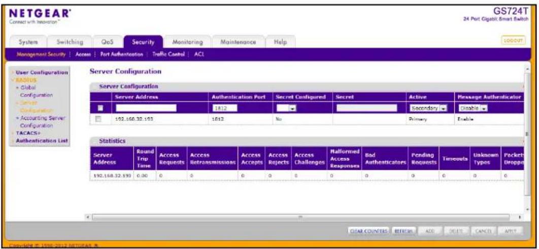
To configure a RADIUS server:
- To add a RADIUS server, specify the settings the following list describes, and click Add.
• In the Server Address field, specify the IP address of the RADIUS server to add.
- In the Authentication Port field, specify the UDP port number the server uses to verify the RADIUS server authentication. The valid range is 0–65535.
- From the Secret Configured menu, select Yes to add a RADIUS secret in the next field. You must select Yes before you can configure the RADIUS secret. After you add the RADIUS server, this field indicates whether the shared secret for this server has been configured.
- In the Secret field, type the shared secret text string used for authenticating and encrypting all RADIUS communications between the switch and the RADIUS server. This secret must match the RADIUS encryption.
• From the Active menu, specify whether the server is a Primary or Secondary server.
- From the Message Authenticator menu, enable or disable the message authenticator attribute for the selected server.
- To modify settings for a RADIUS server that is already configured on the switch, select the check box next to the server address, update the desired fields, and click Apply.
- Click Refresh to update the page with the most current information.
- To delete a configured RADIUS server, select the check box next to the server address, and then click Delete.
- Click Cancel to cancel the configuration on the screen and reset the data on the screen to the latest value of the switch.
The following table describes the RADIUS server statistics available on the page.
| Field Description | |
| Server Address This displays all configured RADIUS servers. | |
| Round Trip Time The time interval, in hundredths of a second, between the most recent Access-Reply/Access-Challenge and the Access-Request that matched it from this RADIUS authentication server. | |
| Access Requests The number of RADIUS Access-Request packets sent to this server. This number does not include retransmissions. | |
| Access Retransmissions The number of RADIUS Access-Request packets retransmitted to this server. | |
| Access Accepts The number of RADIUS Access-Accept packets, including both valid and invalid packets, that were received from this server. | |
| Access Rejects The number of RADIUS Access-Reject packets, including both valid and invalid packets, that were received from this server. | |
| Access Challenges The number of RADIUS Access-Challenge packets, including both valid and invalid packets, that were received from this server. | |
| Malformed Access Responses | The number of malformed RADIUS Access-Response packets received from this server. Malformed packets include packets with an invalid length. Bad authenticators or signature attributes or unknown types are not included as malformed access-responses. |
| Bad Authenticators The number of RADIUS Access-Response packets containing invalid authenticators or signature attributes received from this server. | |
| Pending Requests The number of RADIUS Access-Request packets destined for this server that have not yet timed out or received a response. | |
| Timeouts The number of authentication timeouts to this server. | |
| Unknown Types The number of RADIUS packets of unknown type which were received from this server on the authentication port. | |
| Packets Dropped The number of RADIUS packets received from this server on the authentication port and dropped for some other reason. | |
Use the buttons at the bottom of the page to perform the following actions:
- Click Clear Counters to clear the authentication server and RADIUS statistics to their default values.
- Click Refresh to refresh the page with the most current data from the switch.
Accounting Server Configuration
Use the RADIUS Accounting Server Configuration page to view and configure various settings for one or more RADIUS accounting servers on the network.
To access the RADIUS Accounting Server Configuration page, click Security > Management Security > RADIUS > Accounting Server Configuration.
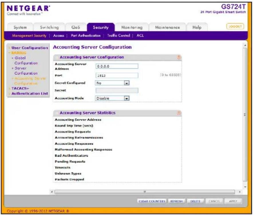
To configure the RADIUS accounting server:
- In the Accounting Server Address field, specify the IP address of the RADIUS accounting server to add.
- In the Port field, specify the UDP port number the server uses to verify the RADIUS accounting server authentication. The valid range is 0–65535.
- From the Secret Configured menu, select Yes to add a RADIUS secret in the next field. You must select Yes before you can configure the RADIUS secret. After you add the RADIUS accounting server, this field indicates whether the shared secret for this server has been configured.
- In the Secret field, type the shared secret to use with the specified accounting server.
- From the Accounting Mode menu, enable or disable the RADIUS accounting mode.
- Click Apply to update the switch with the RADIUS Accounting server settings.
- To delete a configured RADIUS Accounting server, click Delete.
- Click Cancel to cancel the configuration on the screen and reset the data on the screen to the latest value of the switch.
The following table describes RADIUS accounting server statistics available on the page.
| Field Description | |
| Accounting Server Address Displays the IP address of the supported RADIUS accounting server. | |
| Round Trip Time (secs) Displays the time interval, in hundredths of a second, between the most recent Accounting-Response and the Accounting-Request that matched it from this RADIUS accounting server. | |
| Accounting Requests The number of RADIUS Accounting-Request packets sent to this server. This number does not include retransmissions. | |
| Accounting Retransmissions The number of RADIUS Accounting-Request packets retransmitted to this server. | |
| Accounting Responses Displays the number of RADIUS packets received on the accounting port from this server. | |
| Malformed Accounting Responses | Displays the number of malformed RADIUS Accounting-Response packets received from this server. Malformed packets include packets with an invalid length. Bad authenticators and unknown types are not included as malformed accounting responses. |
| Bad Authenticators Displays the number of RADIUS Accounting-Response packets that contained invalid authenticators received from this accounting server. | |
| Pending Requests The number of RADIUS Accounting-Request packets destined for this server that have not yet timed out or received a response. | |
| Timeouts The number of accounting timeouts to this server. | |
| Unknown Types The number of RADIUS packets of unknown type which were received from this server on the accounting port. | |
| Packets Dropped The number of RADIUS packets received from this server on the accounting port and dropped for some other reason. | |
Use the buttons at the bottom of the page to perform the following actions:
- Click Clear Counters to reset all statistics to their default value.
- Click Refresh to update the page with the most current information.
Configuring TACACS+
TACACS+ provides a centralized user management system, while still retaining consistency with RADIUS and other authentication processes. TACACS+ provides the following services:
- Authentication: Provides authentication during login and via user names and user-defined passwords.
- Authorization: Performed at login. When the authentication session is completed, an authorization session starts using the authenticated user name. The TACACS+ server checks the user privileges.
The TACACS+ protocol ensures network security through encrypted protocol exchanges between the device and TACACS+ server.
The TACACS+ folder contains links to the following features:
- Configuring TACACS+ on page 181
• TACACS+ Server Configuration on page 182
TACACS+ Configuration
The TACACS+ Configuration page contains the TACACS+ settings for communication between the switch and the TACACS+ server you configure via the inband management port.
To display the TACACS+ Configuration page, click Security > Management Security, and then click the TACACS+ > TACACS+ Configuration link.
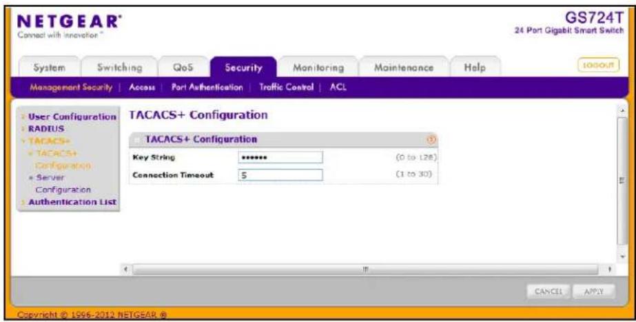
To configure global TACACS+ settings:
- In the Key String field, specify the authentication and encryption key for TACACS+ communications between the GS716T and GS724T and the TACACS+ server. The valid range is 0–128 characters. The key must match the key configured on the TACACS+ server.
- In the Connection Timeout field, specify the maximum number of seconds allowed to establish a TCP connection between the GS716T and GS724T and the TACACS+ server. The valid range is 1–30 seconds.
- Click Cancel to cancel the configuration on the screen and reset the data on the screen to the latest value of the switch.
- If you make any changes to the page, click Apply to apply the new settings to the system.
TACACS+ Server Configuration
Use the TACACS+ Server Configuration page to configure up to five TACACS+ servers with which the switch can communicate.
To display the TACACS+ Server Configuration page, click Security > Management Security, and then click the TACACS+ > Server Configuration link.
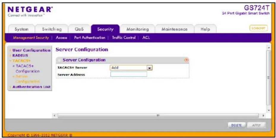
To configure TACACS+ server settings:
- To add a new TACACS+ server, select Add from the TACACS+ Server field, enter the IP address of the server to add, and click Apply.
After you add one or more TACACS+ servers, additional fields appear on the TACACS+ Server Configuration page.
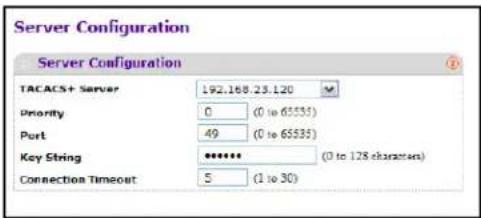
- In the Priority field, specify the order in which the TACACS+ servers are used. A value of 0 is the highest priority.
- In the Port field, specify the authentication port number through which the TACACS+ session occurs. The default is port 49, and the range is 0–65535.
- In the Key String field, specify the authentication and encryption key for TACACS+ communications between the GS716T and GS724T and the TACACS+ server. This key must match the encryption used on the TACACS+ server. The valid range is 0–128 characters.
- In the Connection Timeout field, specify the amount of time that passes before the connection between the device and the TACACS+ server times out. The field range is from 1 to 30 seconds.
- If you make changes to the page, or add a new entry, click Apply to apply the changes to the system.
- To delete a configured TACACS+ server, select the IP address of the server from the TACACS+ Server drop down menu, and then click Delete.
Authentication List Configuration
Use the Authentication List page to configure the default login list. A login list specifies one or more authentication methods to validate switch or port access for the admin user.
Note: Admin is the only user on the system and is assigned to a preconfigured list named defaultList, which you cannot delete.
To access the Authentication List page, click Security > Management Security, and then click the Authentication List link.
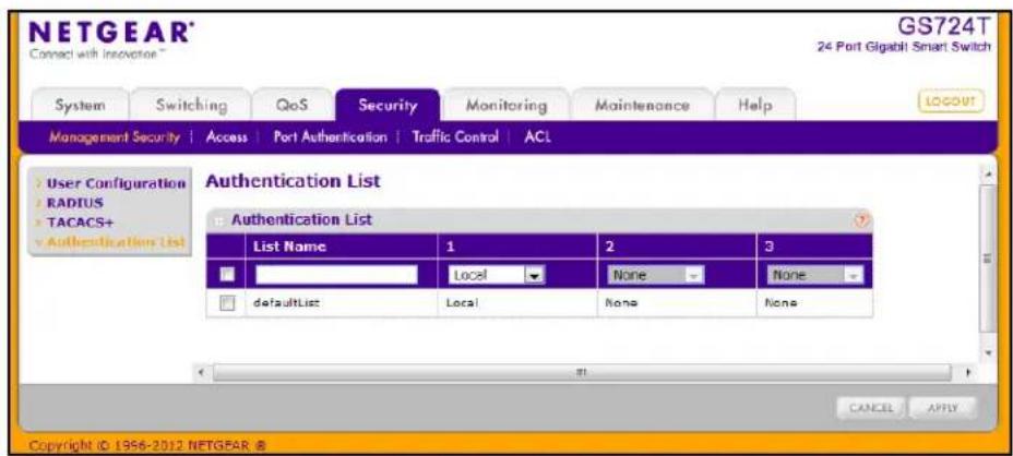
To change the authentication method for the defaultList:
-
Select the check box next to the defaultList name
-
Use the drop down menu in the 1 column to select the authentication method that should appear first in the selected authentication login list. If you select a method that does not time out as the first method, such as 'local', no other method will be tried, even if you have specified more than one method. This parameter will not appear when you first create a new login list. User authentication occurs in the order the methods are selected. Possible methods are as follows:
- Local: The user's locally stored ID and password will be used for authentication. Since the local method does not time out, if you select this option as the first method, no other method will be tried, even if you have specified more than one method.
- RADIUS: The user's ID and password will be authenticated using the RADIUS server. If you select RADIUS or TACACS+ as the first method and an error occurs during the authentication, the switch uses Method 2 to authenticate the user.
- TACACS+: The user's ID and password will be authenticated using the TACACS+ server. If you select RADIUS or TACACS+ as the first method and an error occurs during the authentication, the switch attempts user authentication Method 2.
- None: The authentication method is unspecified. This option is only available for Method 2 and Method 3.
- Use the menu in the 2 column to select the authentication method, if any, that should appear second in the selected authentication login list. This is the method that will be used if the first method times out. If you select a method that does not time out as the second method, the third method will not be tried. This parameter will not appear when you first create a new login list.
- Use the menu in the 3 column to select the authentication method, if any, that should appear third in the selected authentication login list. This parameter will not appear when you first create a new login list.
- Click Cancel to cancel the configuration on the screen and reset the data on the screen to the latest value of the switch.
- If you make changes to the page, click Apply to apply the changes to the system.
Configuring Management Access
From the Access page, you can configure HTTP and Secure HTTP access to the GS716T and GS724T management interface. You can also configure Access Control Profiles and Access Rules.
The Security > Access tab contains the following folders:
- HTTP Configuration on page 186
- Secure HTTP Configuration on page 187
• Certificate Download on page 188 - Access Profile Configuration on page 190
- Access Rule Configuration on page 192
HTTP Configuration
Use the HTTP Configuration page to configure the HTTP server settings on the system.
To access the HTTP Configuration page, click the Security tab, then click Access, and then click the HTTP > HTTP Configuration link.
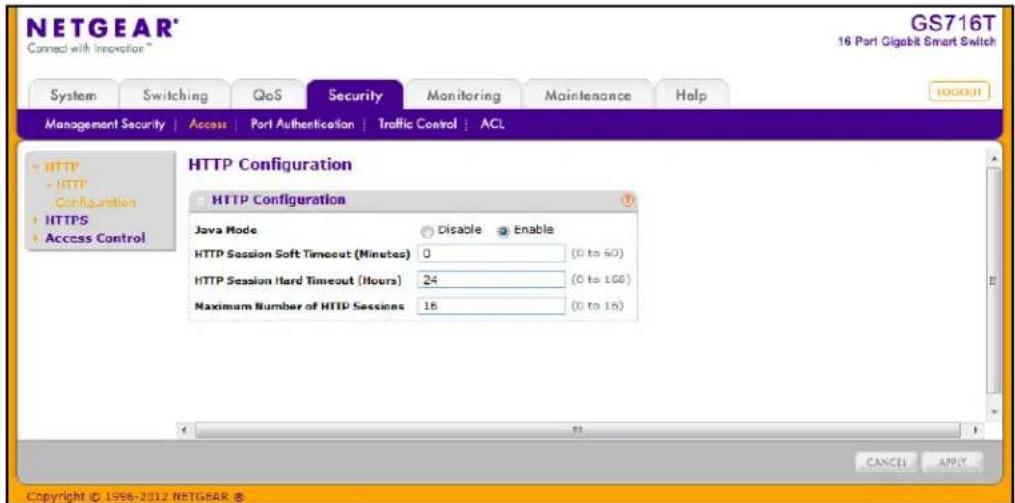
To configure the HTTP server settings:
-
Enable or disable the Web Java Mode. This applies to both secure and un-secure HTTP connections. The currently configured value is shown when the Web page is displayed. The default value is Enable.
-
In the HTTP Session Soft Timeout field, specify the number of minutes an HTTP session can be idle before a timeout occurs.
After the session is inactive for the configured amount of time, the administrator is automatically logged out and must re-enter the password to access the management interface. A value of zero corresponds to an infinite timeout. The default value is 5 minutes. The currently configured value is shown when the Web page is displayed.
- In the HTTP Session Hard Timeout field, specify the hard timeout for HTTP sessions.
This timeout is unaffected by the activity level of the session. The value must be in the range of (0–168) hours. A value of zero corresponds to an infinite timeout. The default value is 24 hours. The currently configured value is shown when the Web page is displayed.
-
In the Maximum Number of HTTP Sessions field, specify the maximum number of HTTP sessions that can exist at the same time. The value must be in the range of (0–16). The default value is 16. The currently configured value is shown when the Web page is displayed.
-
Click Cancel to cancel the configuration on the screen and reset the data on the screen to the latest value of the switch.
-
If you make changes to the page, click Apply to apply the changes to the system.
Secure HTTP Configuration
Secure HTTP enables the transmission of HTTP over an encrypted Secure Sockets Layer (SSL) or Transport Layer Security (TLS) connection. When you manage the switch by using a Web interface, secure HTTP can help ensure that communication between the management system and the switch is protected from eavesdroppers and man-in-the-middle attacks.
Use the Secure HTTP Configuration page to configure the settings for HTTPS communication between the management station and the switch.
To display the Secure HTTP Configuration page, click Security > Access, and then click the HTTPS > HTTPS Configuration link.
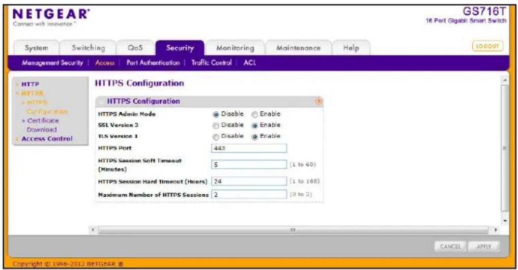
To configure HTTPS settings:
- Use the radio buttons in the HTTPS Admin Mode field to enable or disable the Administrative Mode of Secure HTTP.
The currently configured value is shown when the Web page is displayed. The default value is Disable. You can only download SSL certificates when the HTTPS Admin mode is disabled. - Use the radio buttons in the SSL Version 3 field to enable or disable Secure Sockets Layer Version 3.0. The currently configured value is shown when the Web page is displayed. The default value is Enable.
- Use the radio buttons in the TLS Version 1 field to enable or disable Transport Layer Security Version 1.0. The currently configured value is shown when the Web page is displayed. The default value is Enable.
- In the HTTPS Port field, specify the TCP port to use for HTTPS data. The value must be in the range of 1–65535. Port 443 is the default value. The currently configured value is shown when the Web page is displayed.
- In the HTTPS Session Soft Timeout field, specify the number of minutes an HTTPS session can be idle before a timeout occurs.
After the session is inactive for the configured amount of time, the administrator is automatically logged out and must re-enter the password to access the management interface. A value of zero corresponds to an infinite timeout. The default value is 5 minutes. The currently configured value is shown when the Web page is displayed.
- In the HTTPS Session Hard Timeout field, specify the number of hours an HTTPS session can remain active, regardless of session activity. The value must be in the range of (1–168) hours. The default value is 24 hours. The currently configured value is shown when the Web page is displayed.
- In the Maximum Number of HTTPS Sessions field, specify the maximum number of HTTPS sessions that can be open at the same time. The value must be in the range of (0–2). The default value is 2. The currently configured value is shown when the Web page is displayed.
- Click Cancel to cancel the configuration on the screen and reset the data on the screen to the latest value of the switch.
- If you make changes to the page, click Apply to apply the changes to the system.
Certificate Download
For the Web server on the switch to accept HTTPS connections from a management station, the Web server needs a public key certificate. You can generate a certificate externally (for example, off-line) and download it to the switch.
To display the Certificate Download page, click Security > Access, and then click the HTTPS > Certificate Download link.
Downloading SSL Certificates
Before you download a file to the switch, the following conditions must be true:
- The file to download from the TFTP server is on the server in the appropriate directory.
- The file is in the correct format.
- The switch has a path to the TFTP server.
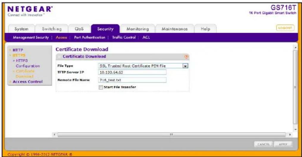
To configure the certificate download settings for HTTPS sessions:
-
From the File Type menu, select the type of SSL certificate to download, which can be one of the following:
-
SSL Trusted Root Certificate PEM File. SSL Trusted Root Certificate File (PEM Encoded).
- SSL Server Certificate PEM File. SSL Server Certificate File (PEM Encoded).
- SSL DH Weak Encryption Parameter PEM File. SSL Diffie-Hellman Weak Encryption Parameter File (PEM Encoded).
-
SSL DH Strong Encryption Parameter PEM File. SSL Diffie-Hellman Strong Encryption Parameter File (PEM Encoded).
-
In the TFTP Server IP field, specify the address of the TFTP server. The address can be an IP address in standard x.x.x.x format or a host name. The host name must start with a letter of the alphabet. Make sure that the software image or other file to be downloaded is available on the TFTP server.
- In the Remote File Name field, specify the name of the file to download, including the path. You may enter up to 32 characters.
- Select the Start File Transfer check box.
- Click Apply to start the transfer. A status message displays during the transfer and upon successful completion of the transfer.
- Click Cancel to cancel the configuration on the screen and reset the data on the screen to the latest value of the switch.
Access Profile Configuration
Use the Access Profile Configuration page to configure settings that control management access to the switch. Access profile configuration requires three steps:
- Use the Access Profile Configuration page to create an access profile. To add rules to the profile, the access profile must be deactivated, which is the default setting.
- Use the Access Rule Configuration page to add one or more access rules to the profile.
- Return to the Access Profile Configuration page to activate the profile.
To access the Access Profile Configuration page, click Security > Access, and then click the Access Control > Access Profile Configuration link.
In the following figure, a profile called mgmt_access has been created, and one rule has been added to the profile.
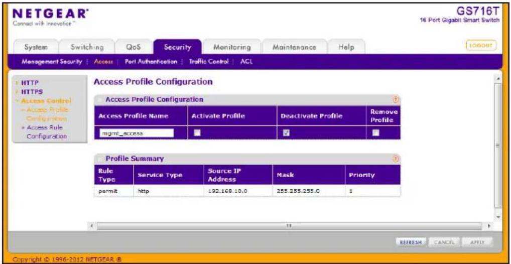
To create an Access Profile:
- In the Access Profile Name field, specify the name of the access profile to be added. The maximum length is 15 characters.
- To activate an access profile, select the Activate Profile check box. You cannot add rules to an active profile.
- To deactivate an access profile, select the Deactivate Profile check box.
- To remove an access profile, select the Remove Profile check box. The access profile should be deactivated before removing the access profile.
- Click Cancel to cancel the configuration on the screen and reset the data on the screen to the latest value of the switch.
- If you make changes to the page, click Apply to apply the changes to the system.
The Profile Summary table shows the rules that are configured for the profile, as the following table describes.
| Field Description | |
| Rule Type Identifies the action | the rule takes, which is either Permit or Deny. |
| Service Type Displays the type | of service to allow or prohibit from accessing the switch management interface:• SNMP• HTTP• HTTPS |
| Source IP Address Displays the | IP Address of the client that may or may not originate management traffic. |
| Mask Displays the subnet mask | associated with the IP address. |
| Priority Displays the priority of | the rule. The rules are validated against the incoming management request in the ascending order of their priorities. If a rule matches, action is performed and subsequent rules below are ignored. |
Click Refresh to update the page with the most current information.
Access Rule Configuration
Use the Access Rule Configuration page to configure the rules about what systems can access the GS716T and GS724T Web interface and what protocols are allowed.
To access the Access Rule Configuration page, click Security > Access, and then click the Access Control > Access Rule Configuration link.
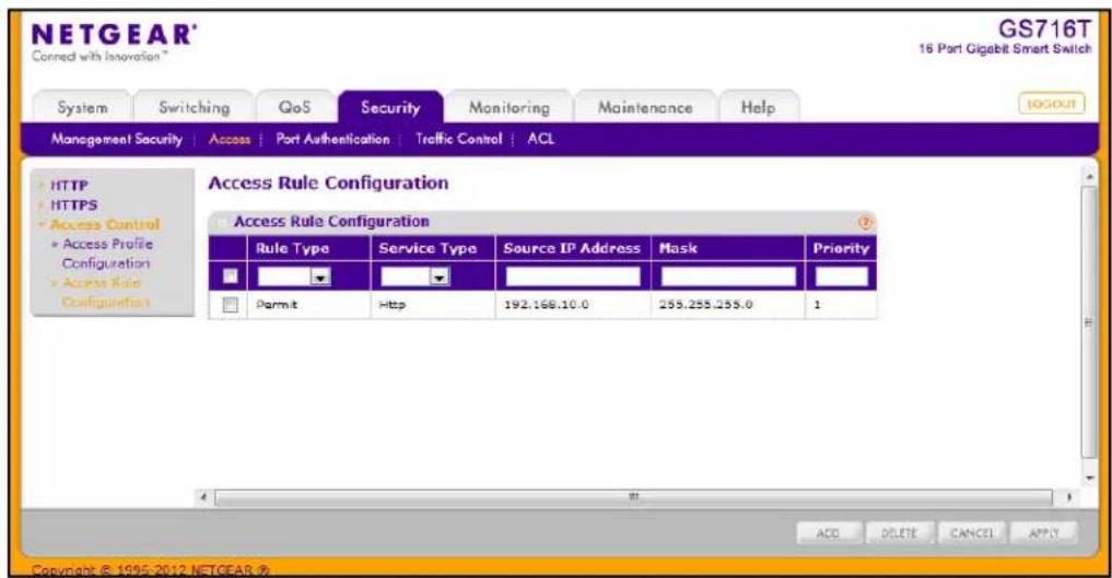
Before you create access rules, make sure:
• An access profile exists.
• The access profile is deactivated.
To configure access profile rules:
- To add an access profile rule, configure the following settings and click Add.
- Rule Type: Specify whether the rule permits or denies access to the GS716T and GS724T management interface.
- Select Permit to allow access to the management interface for traffic that meets the criteria you configure for the rule. Any traffic that does not meet the rules is denied.
- Select Deny to prohibit access to the management interface for traffic that meets the criteria you configure for the rule. Any traffic that does not meet the rules is allowed access to the switch. Unlike MAC ACLs and IP ACLs, there is no implied deny all rule at the end of the rule list.
- Service Type. Select the type of service to allow or prohibit from accessing the switch management interface:
• SNMP
- HTTP
- HTTPS
- Source IP Address. Specify the IP Address of the client originating the management traffic.
- Mask. Specify the subnet mask associated with the IP address. The subnet mask is a standard subnet mask, and not an inverse (wildcard) mask that you use with IP ACLs.
-
Priority. Configure priority to the rule. The rules are validated against the incoming management request in the ascending order of their priorities. If a rule matches, action is performed and subsequent rules below are ignored. For example, if a Source IP 10.10.10.10 is configured with priority 1 to permit, and Source IP 10.10.10.10 is configured with priority 2 to Deny, then access is permitted if the profile is active, and the second rule is ignored.
-
To modify an access rule, select the check box next to the Rule Type, update the desired settings, and click Apply
-
To delete an access rule, select the check box next to the Rule Type, and click Delete.
-
Click Cancel to cancel the configuration on the screen and reset the data on the screen to the latest value of the switch.
Port Authentication
In port-based authentication mode, when 802.1X is enabled globally and on the port, successful authentication of any one supplicant attached to the port results in all users being able to use the port without restrictions. At any given time, only one supplicant is allowed to attempt authentication on a port in this mode. Ports in this mode are under bidirectional control. This is the default authentication mode.
The 802.1X network has three components:
• Authenticators: Specifies the port that is authenticated before permitting system access.
- Supplicants: Specifies the host connected to the authenticated port requesting access to the system services.
- Authentication Server: Specifies the external server, for example, the RADIUS server that performs the authentication on behalf of the authenticator, and indicates whether the user is authorized to access system services.
From the Port Authentication link, you can access the following pages:
- Basic:
• 802.1X Configuration on page 194 - Advanced:
• Port Authentication on page 195
• Port Summary on page 198
802.1X Configuration
Use the 802.1X Configuration page to enable or disable port access control on the system.
To display the 802.1X Configuration page, click Security > Port Authentication > Basic > 802.1X Configuration.
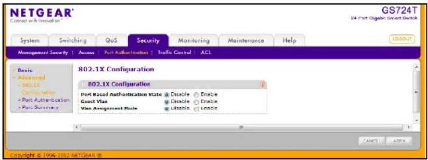
To configure global 802.1X settings:
- Select the appropriate radio button in the Port Based Authentication State field to enable or disable 802.1X administrative mode on the switch.
- Enable. Port-based authentication is permitted on the switch.
Note: If 802.1X is enabled, authentication is performed by a RADIUS server. This means the primary authentication method must be RADIUS. To set the method, go to Security > Management Security > Authentication List and select RADIUS as method 1 for defaultList. For more information, see Authentication List Configuration on page 184.
- Disable. The switch does not check for 802.1X authentication before allowing traffic on any ports, even if the ports are configured to allow only authenticated users.
- Enable or disable the Guest VLAN supplicant mode.
- Enabled. When no 802.1X supplicant is authenticated on a port, the port still provides limited network access, as determined by a guest VLAN configured on the authentication server.
- Disabled. A guest VLAN cannot be used for unauthorized ports.
- Enable or disable the VLAN Assignment mode:
- Enable. Allow a RADIUS server to assign the VLAN ID to authenticated supplicants.
- Disable. The RADIUS server can not assign authenticated clients to VLANs.
-
Click Cancel to cancel the configuration on the screen and reset the data on the screen to the latest value of the switch.
-
If you change the settings, click Apply to apply the new settings to the system.
Port Authentication
Use the Port Authentication page to enable and configure port access control on one or more ports.
To access the Port Authentication page, click Security > Port Authentication, and then click the Advanced > Port Authentication link.
Note: Use the horizontal scroll bar at the bottom of the browser to view all the fields on the Port Authentication page. The figures on the following page are both images of the Port Authentication page.
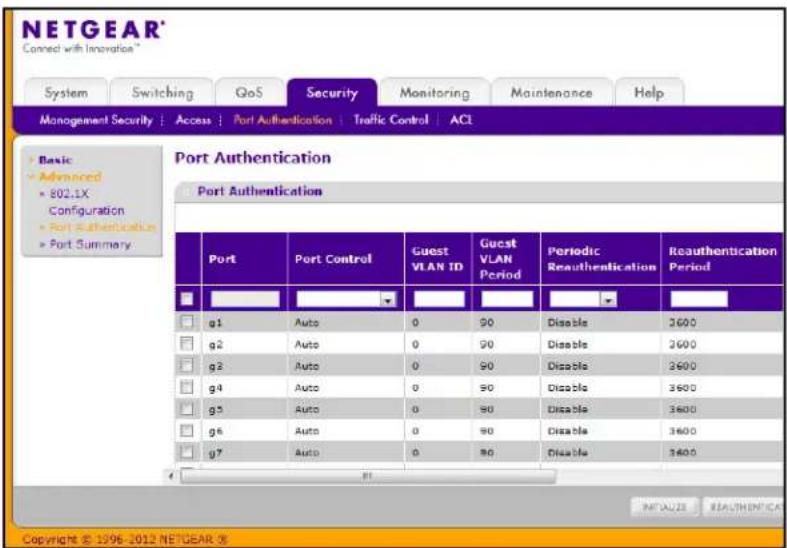
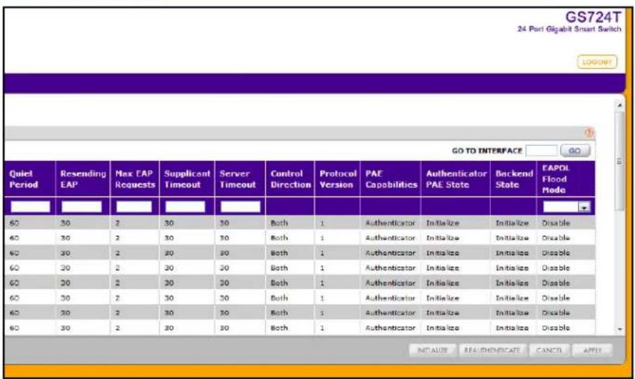
To configure 802.1X settings for the port:
-
Select the check box next to the port to configure. You can also select multiple check boxes to apply the same settings to the select ports, or select the check box in the heading row to apply the same settings to all ports.
-
For the selected port(s), specify the following settings:
-
Port Control. Defines the port authorization state. The control mode is only set if the link status of the port is link up. The possible field values are:
- Auto: Automatically detects the mode of the interface.
- Authorized: Places the interface into an authorized state without being authenticated. The interface sends and receives normal traffic without client port-based authentication.
- Unauthorized: Denies the selected interface system access by moving the interface into unauthorized state. The switch cannot provide authentication services to the client through the interface.
- Guest VLAN ID. This field allows the user to configure the Guest VLAN ID on the interface. The valid range is 0–4093. The default value is 0. Enter 0 to reset the Guest VLAN ID on the interface.
- Guest VLAN Period. This input field allows the user to enter the Guest VLAN period for the selected port. The Guest VLAN period is the value, in seconds, of the timer used by the Guest VLAN Authentication. The Guest VLAN timeout must be a value in the range of 1–300. The default value is 90.
- Periodic Reauthentication. Use this field to enable or disable reauthentication of the supplicant for the specified port. Select Enable and Disable. If the value is Enable, reauthentication will occur. Otherwise, reauthentication will not be allowed. The default value is Disable. Changing the selection will not change the configuration until the Apply button is pressed.
- Reauthentication Period. Indicates the time span in which the selected port is reauthenticated. The field value is in seconds. The range is 1–65535, and the field default is 3600 seconds.
- Quiet Period. Defines the amount of time that the switch remains in the quiet state following a failed authentication exchange. The possible field range is 0–65535. The field value is in seconds. The field default is 60 seconds.
- Resending EAP. This input field allows you to configure the transmit period for the selected port. The transmit period is the value, in seconds, of the timer used by the authenticator state machine on the specified port to determine when to send an EAPOL EAP Request/Identify frame to the supplicant. The transmit period must be a number in the range of 1–65535. The default value is 30. Changing the value will not change the configuration until you click the Apply button.
- Max EAP Requests. This input field allows you to enter the maximum requests for the selected port. The maximum requests value is the maximum number of times the authenticator state machine on this port will retransmit an EAPOL EAP
Request/Identity before timing out the supplicant. The maximum requests value must be in the range of 1–10. The default value is 2. Changing the value will not change the configuration until you click the Apply button.
- Supplicant Timeout. Defines the amount of time that lapses before EAP requests are resent to the user. The field value is in seconds. The field default is 30 seconds.
- Server Timeout. Defines the amount of time that lapses before the switch resends a request to the authentication server. The field value is in seconds. The range is 1–65535, and the field default is 30 seconds.
- Control Direction. This displays the control direction for the specified port, which is always Both. The control direction dictates the degree to which protocol exchanges take place between Supplicant and Authenticator. The unauthorized controlled port exerts control over communication in both directions (disabling both incoming and outgoing frames). This field is not configurable.
- Protocol Version. This field displays the protocol version associated with the selected port. The only possible value is 1, corresponding to the first version of the 802.1X specification. This field is not configurable.
- PAE Capabilities. This field displays the port access entity (PAE) functionality of the selected port. Possible values are Authenticator or Supplicant. This field is not configurable.
- Authenticator PAE State. This field displays the current state of the authenticator PAE state machine. Possible values are as follows:
- Initialize
- Disconnected
- Connecting
- Authenticating
- Authenticated
- Aborting
• Held - ForceAuthorized
- ForceUnauthorized
- Backend State. This field displays the current state of the backend authentication state machine. Possible values are as follows:
- Request
- Response
- Success
- Fail
- Timeout
- Initialize
- Idle
- EAPOL Flood Mode. This field is used to enable or disable the EAPOL Flood mode per Interface. The default value is Disable.
-
Click Apply to send the updated screen to the switch and cause the changes to occur on the switch and the changes will be saved.
-
Click Initialize to begin the initialization sequence on the selected port(s). This button is only selectable if the control mode is auto. If the button is not selectable, it will be grayed out. When this button is clicked, the action is immediate. It is not required to click Apply for the action to occur.
- Click Reauthenticate to begin the reauthentication sequence on the selected port. This button is only selectable if the control mode is auto. If the button is not selectable, it will be grayed out. When this button is pressed, the action is immediate. It is not required to click Apply for the action to occur.
- Click Cancel to cancel the configuration on the screen and reset the data on the screen to the latest value of the switch.
Port Summary
Use the Port Summary page to view information about the port access control settings on a specific port.
To access the Port Summary page, click Security > Port Authentication > Advanced > Port Summary.
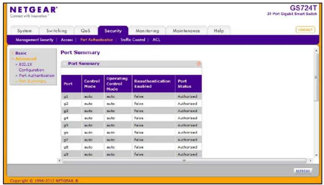
The following table describes the fields on the Port Summary page.
| Field Description | |
| Port The port whose settings are displayed in the current table row. | |
| Control Mode Defines the port | authorization state. The control mode is only set if the link status of the port is link up. The possible field values are:• Auto : Automatically detects the mode of the interface.• Force Authorized : Places the interface into an authorized state without being authenticated. The interface sends and receives normal traffic without client port-based authentication.• Force Unauthorized : Denies the selected interface system access by moving the interface into unauthorized state. The switch cannot provide authentication services to the client through the interface. |
| Operating Control Mode This field indicates the control mode under which the port is actually operating. Possible values are:• ForceUnauthorized• ForceAuthorized• Auto• N/A: If the port is in detached state it cannot participate in port access control. | |
| Reauthentication Enabled | Displays if reauthentication is enabled on the selected port. This is a configurable field. The possible values are true and false. If the value is true, reauthentication will occur. Otherwise, reauthentication will not be allowed. |
| Port Status This field displays the authorization status of the specified port. The possible values are Authorized, Unauthorized, and N/A. If the port is in detached state, the value will be N/A since the port cannot participate in port access control. | |
Click Refresh to update the information on the screen.
Traffic Control
From the Traffic Control link, you can configure MAC Filters, Storm Control, Port Security, and Protected Port settings. To display the page, click the Security > Traffic Control tab.
The Traffic Control folder contains links to the following features:
- MAC Filter:
• MAC Filter Configuration on page 200
• MAC Filter Summary on page 202
• Storm Control on page 203
- Port Security:
• Port Security Configuration on page 204
• Port Security Interface Configuration on page 205
• Security MAC Address on page 207
• Protected Ports Membership on page 208
MAC Filter Configuration
Use the MAC Filter Configuration page to create MAC filters that limit the traffic allowed into and out of specified ports on the system.
To display the MAC Filter Configuration page, click Security > Traffic Control, and then click the MAC Filter > MAC Filter Configuration link.
In the following figure, the source and destination port member areas have been expanded to show the ports. Click the orange bar to show the ports or LAGs.
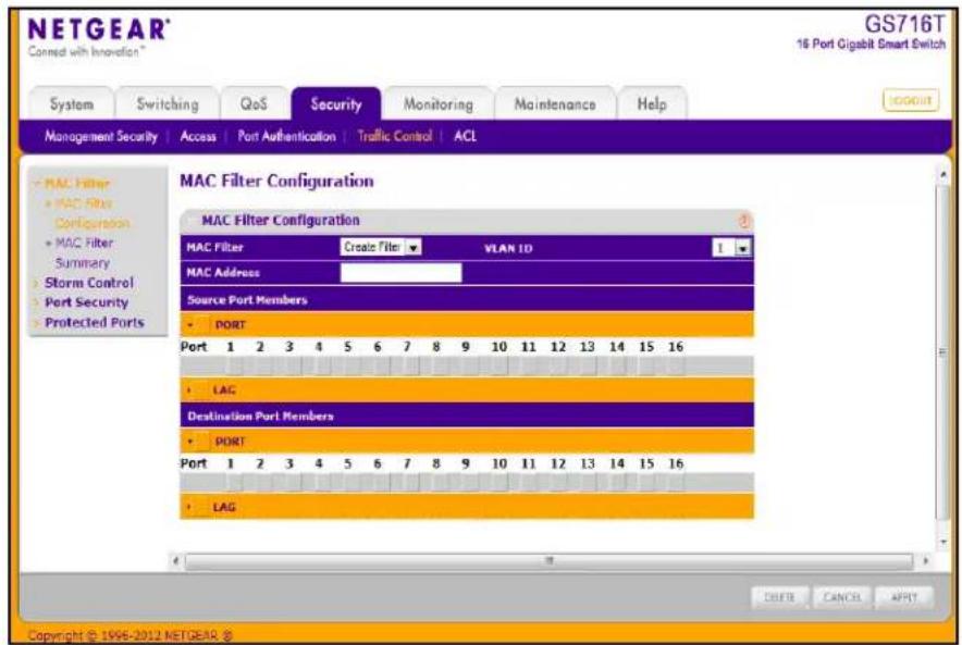
To configure MAC filter settings:
- To configure a new MAC filter:
a. Select Create Filter from the MAC Filter menu. If no filters have been configured, this is the only option available.
b. From the VLAN ID menu, select the VLAN to use with the MAC address to fully identify packets you want filtered. You can change this field only when the Create Filter option is selected from the MAC Filter menu.
c. In the MAC Address field, specify the MAC address of the filter in the format 00:01:1A:B2:53:4D. You can change this field when you have selected the Create Filter option.
You cannot define filters for the following MAC addresses:
• 00:00:00:00:00:00
• 01:80:C2:00:00:00 to 01:80:C2:00:00:0F
• 01:80:C2:00:00:20 to 01:80:C2:00:00:21
- FF:FF:FF:FF:FF:FF
d. Click the orange bar under the Source Port Members heading to display the available ports. Select the port(s) to include in the inbound filter. If a packet with the MAC address and VLAN ID you specify is received on a port that is not in the list, it will be dropped.
e. Click the orange bar under the Destination Port Members heading to display the available ports. Select the port(s) to include in the outbound filter. Packets with the MAC address and VLAN ID you selected will be transmitted only out of ports that are in the list. Destination ports can be included only in the Multicast filter.
-
To delete a configured MAC Filter, select it from the menu, and then click Delete.
-
Click Cancel to cancel the configuration on the screen and reset the data on the screen to the latest value of the switch.
-
If you make changes to the page, click Apply to apply the changes to the system.
MAC Filter Summary
Use the MAC Filter Summary page to view the MAC filters that are configured on the system.
To display the MAC Filter Summary page, click Security > Traffic Control, and then click the MAC Filter > MAC Filter Summary link.
![NETGEAR Connect with Innovation GS716T 16 Port Gigabit Smart Switch System Switching QoS Security Monitoring Maintenance Help MANAGEMENT SECURITY Access Port Authentication Traffic Control ACL MAC Filter Summary MAC Filter Summary MAC Address VLAN ID Somcute Port Members Destination Port Members 01:02:F1:92:B2:56 1 [g6] [g12][g14] Copyright © 1996-2012 NETGEAR. ©](/content/2026/05/825774/images/9d8bfe47b46e8a5ef1ee967158b02fddebd4fea7eac564f213f7a8697dd8a292.jpg)
The following table describes the information displayed on the page:
| Field Description | |
| MAC Address Identifies the MAC address that is filtered. | |
| VLAN ID The VLAN ID | used with the MAC address to fully identify packets you want filtered.You can only change this field when you have selected theCreate Filteroption. |
| Source Port Members | Displays the ports included in the inbound filter. |
| Destination Port Members | Displays the ports included in the outbound filter. |
Click Refresh to update the page with the most current information.
Storm Control
A broadcast storm is the result of an excessive number of broadcast messages simultaneously transmitted across a network by a single port. Forwarded message responses can overload network resources and/or cause the network to time out.
The switch measures the incoming broadcast/multicast/unknown unicast packet rate per port and discards packets when the rate exceeds the defined value. Storm control is enabled per interface, by defining the packet type and the rate at which the packets are transmitted.
To display the Storm Control page, click Security > Traffic Control, and then click the Storm Control link.
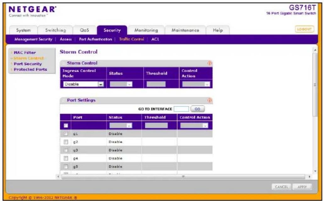
To configure storm control settings:
- Select the check box next to the port to configure. Select multiple check boxes to apply the same setting to all selected ports. Select the check box in the heading row to apply the same settings to all ports.
- From the Ingress Control Mode menu, select the mode of broadcast affected by storm control.
- Disable. Do not use storm control.
- Unknown Unicast. If the rate of unknown L2 unicast (destination lookup failure) traffic ingressing on an interface increases beyond the configured threshold, the traffic will be dropped.
- Multicast. If the rate of L2 multicast traffic ingressing on an interface increases beyond the configured threshold, the traffic will be dropped.
-
Broadcast. If the rate of L2 broadcast traffic ingressing on an interface increases beyond the configured threshold, the traffic will be dropped.
-
When the selected Ingress Control Mode is an option other than Disable, select Enable or Disable from the Status menu to specify the administrative status of the mode.
- In the Threshold field, specify the maximum rate at which unknown packets are forwarded. The range is a percent of the total threshold between 0–100%. The default is 5%.
- Click Cancel to cancel the configuration on the screen and reset the data on the screen to the latest value of the switch.
- If you make changes to the page, click Apply to apply the changes to the system.
Port Security Configuration
Use the Port Security feature to lock one or more ports on the system. When a port is locked, only packets with an allowable source MAC addresses can be forwarded. All other packets are discarded.
To display the Port Security Configuration page, click Security > Traffic Control, and then click the Port Security > Port Security Configuration link.
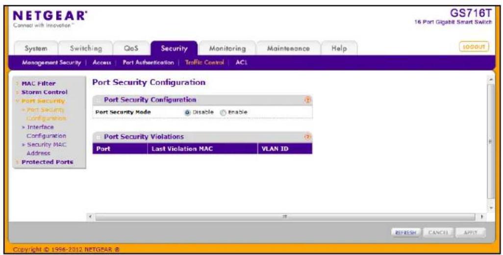
To configure the global port security mode:
- In the Port Security Mode field, select the appropriate radio button to enable or disable port security on the switch.
- Click Cancel to cancel the configuration on the screen and reset the data on the screen to the latest value of the switch.
- If you change the mode, click Apply to apply the change to the system.
The Port Security Violation table shows information about violations that occurred on ports that are enabled for port security. The following table describes the fields in the Port Security Violation table.
| Field Description | |
| Port Identifies the port | where a violation occurred. |
| Last Violation MAC Displays the source MAC address of the last packet that was discarded at a locked port. | |
| VLAN ID Displays the VLAN ID corresponding to the Last Violation MAC address. | |
Click Refresh to refresh the page with the most current data from the switch.
Port Security Interface Configuration
A MAC address can be defined as allowable by one of two methods: dynamically or statically. Both methods are used concurrently when a port is locked.
Dynamic locking implements a first arrival mechanism for Port Security. You specify how many addresses can be learned on the locked port. If the limit has not been reached, then a packet with an unknown source MAC address is learned and forwarded normally. When the limit is reached, no more addresses are learned on the port. Any packets with source MAC addresses that were not already learned are discarded. You can effectively disable dynamic locking by setting the number of allowable dynamic entries to zero.
Static locking allows you to specify a list of MAC addresses that are allowed on a port. The behavior of packets is the same as for dynamic locking: only packets with an allowable source MAC address can be forwarded.
To display the Port Security Interface Configuration page, click Security > Traffic Control, and then click the Port Security > Interface Configuration link.
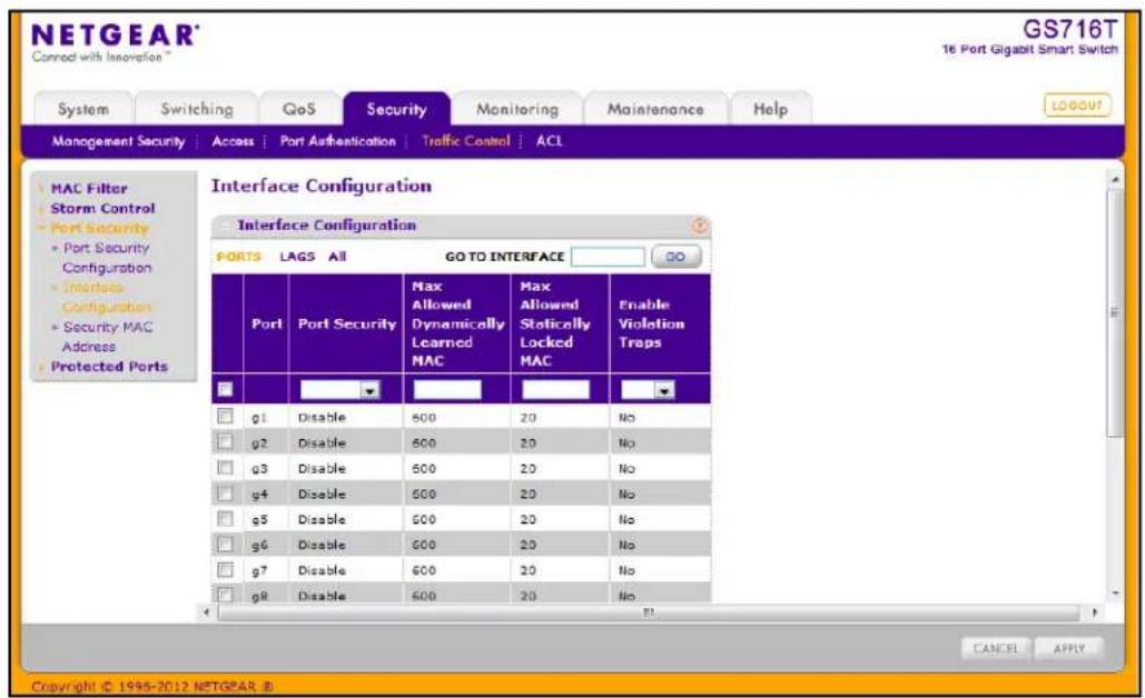
To configure port security settings:
- To configure port security settings for a physical port, click PORTS.
- To configure port security settings for a Link Aggregation Group (LAG), click LAGS.
- To configure port security settings for both physical ports and LAGs, click ALL.
- Select the check box next to the port or LAG to configure. Select multiple check boxes to apply the same setting to all selected interfaces. Select the check box in the heading row to apply the same settings to all interfaces.
- Specify the following settings:
• Port Security. Enable or Disable the port security feature for the selected port.
- Max Allowed Dynamically Learned MAC. Sets the maximum number of dynamically learned MAC addresses on the selected interface. Valid range is 0–600.
- Max Allowed Statically Locked MAC. Sets the maximum number of statically locked MAC addresses on the selected interface. Valid range is 0–20.
- Enable Violation Traps. Enables or disables the sending of new violation traps designating when a packet with a disallowed MAC address is received on a locked port.
-
Click Cancel to cancel the configuration on the screen and reset the data on the screen to the latest value of the switch.
-
If you make changes to the page, click Apply to apply the changes to the system.
Security MAC Address
Use the Security MAC Address page to convert a dynamically learned MAC address to a statically locked address.
To display the Security MAC Address page, click Security > Traffic Control, and then click the Port Security > Security MAC Address link.
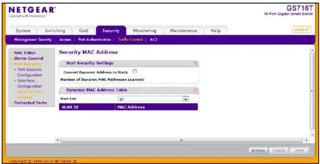
To convert learned MAC addresses:
- Select the Convert Dynamic Address to Static check box.
- Click Apply. The Dynamic MAC Address entries are converted to Static MAC address entries in a numerically ascending order until the Static limit is reached.
The Dynamic MAC Address Table shows the MAC addresses and their associated VLANs learned on the selected port. Use the Port List menu to select the interface for which you want to display data.
| Field Description | |
| VLAN ID Displays the VLAN ID corresponding to the Last Violation MAC address. | |
| MAC Address Displays the MAC addresses learned on a specific port. | |
Click Refresh to refresh the page with the most current data from the switch.
Protected Ports Membership
If a port is configured as protected, it does not forward traffic to any other protected port on the switch, but it will forward traffic to unprotected ports. Use the Protected Ports Membership page to configure the ports as protected or unprotected.
To display the Protected Ports Membership page, click the Security > Traffic Control > Protected Ports link.
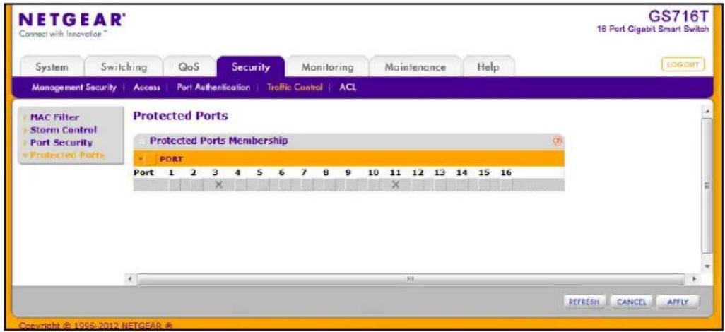
To configure protected ports:
- Click the orange bar to display the available ports.
- Click the box below each port to configure as a protected port. Protected ports are marked with an X. No traffic forwarding is possible between two protected ports.
- Click Refresh to refresh the page with the most current data from the switch.
- Click Cancel to cancel the configuration on the screen and reset the data on the screen to the latest value of the switch.
- If you make changes to the page, click Apply to apply the changes to the system. Configuration changes take effect immediately.
Configuring Access Control Lists
Access Control Lists (ACLs) ensure that only authorized users have access to specific resources while blocking off any unwarranted attempts to reach network resources. ACLs are used to provide traffic flow control, restrict contents of routing updates, decide which types of traffic are forwarded or blocked, and above all provide security for the network. GS716T and GS724T Smart Switches software supports IPv4, IPv6 and MAC ACLs.
The basic steps for configuring an ACL are as follows:
- Create an IPv4-based, IPv6-based, or MAC-based ACL ID.
- Use the ACL Wizard or an ACL Rule page to create and define a rule to associate with an existing ACL. ACL rules define the packet-matching criteria, such as protocols, source, and destination IP and MAC addresses.
- Bind the ACL to a port or to a LAG.
The Security > ACL folder contains links to the following features:
- ACL Wizard
- Basic
• MAC ACL on page 211
• MAC Rules on page 212
• MAC Binding Configuration on page 214
• MAC Binding Table on page 215
- Advanced
• IP ACL on page 216
• IP Rules on page 217
• IP Extended Rules on page 219
- IPv6 ACL on page 222
• IPv6 Rules on page 223
• IP Binding Configuration on page 226
• IP Binding Table on page 227
ACL Wizard
The ACL Wizard allows you to configure ACL permissions for devices based on the source and destination of MAC address, IP address, and port IDs.
To display the MAC ACL page, click Security > ACL Wizard.
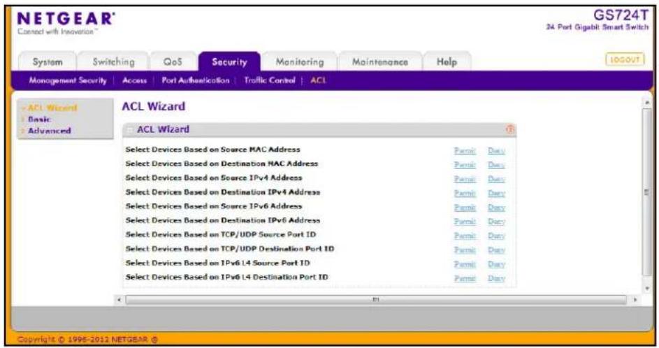
When a packet meets the match criteria of a rule, the specified rule action (Permit or Deny) is taken and the additional rules are not checked for a match; configure as follows:
- Select Devices Based on Source MAC Address. Permit and Deny options are used to configure devices based on source MAC address.
- Select Devices Based on Destination MAC Address. Permit and Deny options are used to configure devices based on destination MAC address.
- Select Devices Based on Source IPv4 Address. Permit and Deny options are used to configure devices based on the source IPv4 address.
- Select Devices Based on Destination IPv4 Address. Permit and Deny options are used to configure devices based on the destination IPv4 address.
- Select Devices Based on Source IPv6 Address. Permit and Deny options are used to configure devices based on the source IPv6 address.
- Select Devices Based on Destination IPv6 Address. Permit and Deny options are used to configure devices based on the destination IPv6 address.
- Select Devices Based on TCP/UDP Source Port ID. Permit and Deny options are used to configure devices based on the TCP/UDP source port ID.
- Select Devices Based on TCP/UDP Destination Port ID. Permit and Deny options are used to configure devices based on the TCP/UDP destination port ID.
- Select Devices Based on IPv6 L4 Source Port ID. Permit and Deny options are used to configure devices based on the IPv6 layer 4 source port ID.
- Select Devices Based on IPv6 L4 Destination Port ID. Permit and Deny options are used to configure devices based on the IPv6 layer 4 destination port ID.
MAC ACL
A MAC ACL consists of a set of rules which are matched sequentially against a packet. When a packet meets the match criteria of a rule, the specified rule action (Permit/Deny) is taken and the additional rules are not checked for a match.
There are multiple steps involved in defining a MAC ACL and applying it to the switch:
- Use the MAC ACL page to create the ACL ID.
- Use the MAC Rules page to create rules for the ACL.
- Use the MAC Binding Configuration page to assign the ACL by its ID number to a port.
- Optionally, use the MAC Binding Table page to view the configurations.
To display the MAC ACL page, click Security > ACL. The MAC ACL page is under the Basic link.
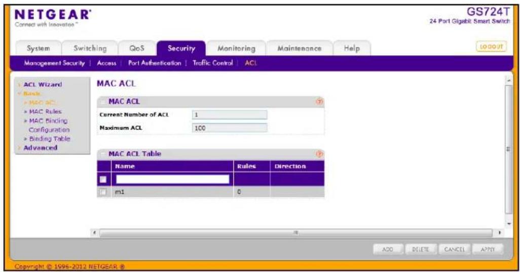
The MAC ACL table displays the number of ACLs currently configured in the switch and the maximum number of ACLs that can be configured. The current size is equal to the number of configured IPv4 ACLs plus the number of configured MAC ACLs.
To configure a MAC ACL:
- To add a MAC ACL, specify a name for the MAC ACL in the Name field, and click Add. The name string may include alphabetic, numeric, dash, underscore, or space characters only. The name must start with an alphabetic character.
Each configured ACL displays the following information:
- Rules. Displays the number of rules currently configured for the MAC ACL.
-
Direction. Displays the direction of packet traffic affected by the MAC ACL, which can be Inbound or blank.
-
To delete a MAC ACL, select the check box next to the Name field, then click Delete.
-
To change the name of a MAC ACL, select the check box next to the Name field, update the name, then click Apply.
-
Click Cancel to cancel the configuration on the screen and reset the data on the screen to the latest value of the switch.
MAC Rules
Use the MAC Rules page to define rules for MAC-based ACLs. The access list definition includes rules that specify whether traffic matching the criteria is forwarded normally or discarded. A default 'deny all' rule is the last rule of every list.
To display the MAC Rules page, click Security > ACL, then click the Basic > MAC Rules link.
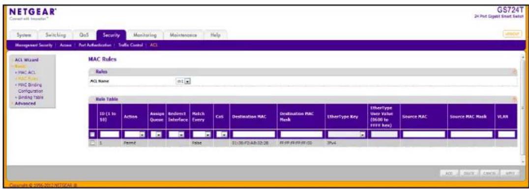
To configure MAC ACL rules:
-
From the ACL Name field, specify the existing MAC ACL to which the rule will apply. To set up a new MAC ACL use the MAC ACL page.
-
To add a new rule, enter an ID for the rule, configure the following settings, and click Add.
• Action. Specify what action should be taken if a packet matches the rule's criteria:
- Permit: Forwards packets that meet the ACL criteria.
- Deny: Drops packets that meet the ACL criteria.
- Assign Queue. Specifies the hardware egress queue identifier used to handle all packets matching this ACL rule. Enter an identifying number from 0–7 in this field.
- Redirect Interface. Specifies the specific egress interface where the matching traffic stream is forced, bypassing any forwarding decision normally performed by the device.
- Match Every. Requires a packet to match the criteria of this ACL. Select True or False from the drop-down menu. Match Every is exclusive to the other filtering rules, so if Match Every is True, the other rules on the screen are not available.
- CoS. Requires a packet's class of service (CoS) to match the CoS value listed here. Enter a CoS value between 0–7 to apply this criteria.
- Destination MAC. Requires an Ethernet frame's destination port MAC address to match the address listed here. Enter a MAC address in this field. The valid format is xx:xx:xx:xx:xx:xx.
- Destination MAC Mask. If desired, enter the MAC Mask associated with the Destination MAC to match. The MAC address mask specifies which bits in the destination MAC to compare against an Ethernet frame. Use Fs and zeros in the MAC mask, which is in a wildcard format. An F means that the bit is not checked, and a zero in a bit position means that the data must equal the value given for that bit. For example, if the MAC address is aa:bb:cc:dd:ee:ff, and the mask is 00:00:ff:ff:ff:ff, all MAC addresses with aa:bb:xx:xx:xx:xx result in a match (where x is any hexadecimal number). A MAC mask of 00:00:00:00:00:00 matches a single MAC address.
- EtherType Key. Requires a packet's EtherType to match the EtherType you select. Select the EtherType value from the drop down menu. If you select User Value, you can enter a custom EtherType value.
- EtherType User Value. This field is configurable if you select User Value from the EtherType drop down menu. The value you enter specifies a customized Ethertype to compare against an Ethernet frame. The valid range of values is 0x0600–0xFFFF.
- Source MAC. Requires a packet's source port MAC address to match the address listed here. Enter a MAC address in the this field. The valid format is xx:xx:xx:xx:xx:xx.
- Source MAC Mask. If desired, enter the MAC mask for the source MAC address to match. Use Fs and zeros in the MAC mask, which is in a wildcard format. An F means that the bit is not checked, and a zero in a bit position means that the data must equal the value given for that bit. The valid format is xx:xx:xx:xx:xx:xx. A MAC mask of 00:00:00:00:00:00 matches a single MAC address.
-
VLAN. Requires a packet's VLAN ID to match the ID listed here. Enter the VLAN ID to apply this criteria. The valid range is 1–4093.
-
Click Cancel to cancel the configuration on the screen and reset the data on the screen to the latest value of the switch.
-
To delete a rule, select the check box associated with the rule and click Delete.
-
To change a rule, select the check box associated with the rule, change the desired fields and click Apply.
MAC Binding Configuration
When an ACL is bound to an interface, all the rules that have been defined are applied to the selected interface. Use the MAC Binding Configuration page to assign MAC ACL lists to ACL Priorities and Interfaces.
To display the MAC Binding Configuration page, click Security > ACL, then click the Basic > MAC Binding Configuration link.
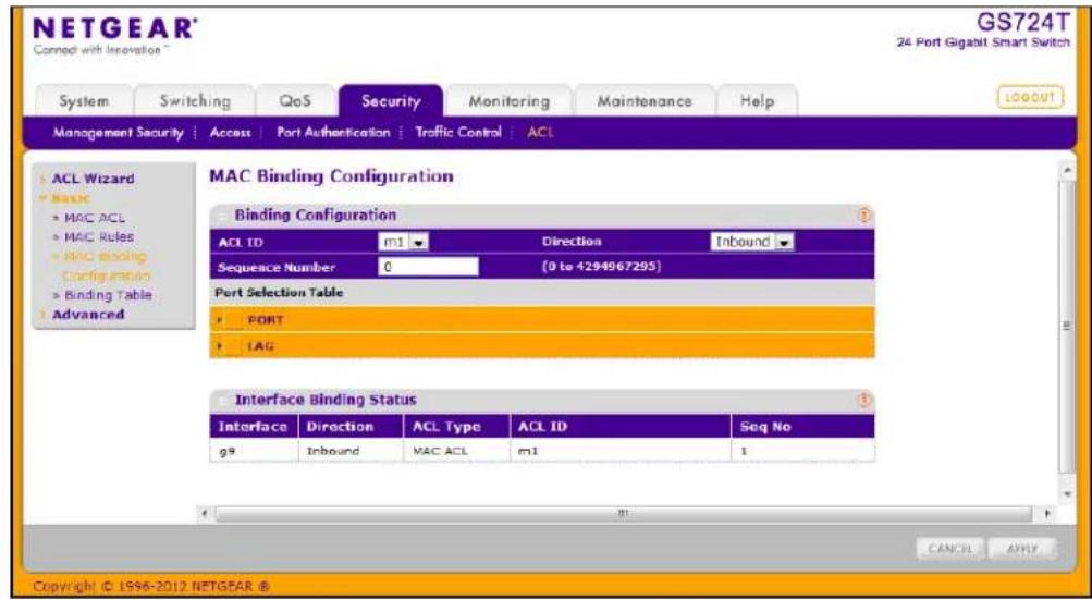
To configure MAC ACL interface bindings:
- Select an existing MAC ACL from the ACL ID menu.
The packet filtering direction for ACL is Inbound, which means the MAC ACL rules are applied to traffic entering the port.
- Specify an optional sequence number to indicate the order of this access list relative to other access lists already assigned to this interface and direction.
A low number indicates high precedence order. If a sequence number is already in use for this interface and direction, the specified access list replaces the currently attached access list using that sequence number. If the sequence number is not specified by the user, a sequence number that is one greater than the highest sequence number currently in use for this interface and direction will be used. The valid range is 1–4294967295.
-
Click the appropriate orange bar to expose the available ports or LAGs.
-
To add the selected ACL to a port or LAG, click the box directly below the port or LAG number so that an X appears in the box.
• To remove the selected ACL from a port or LAG, click the box directly below the port or LAG number to clear the selection. An X in the box indicates that the ACL is applied to the interface. -
Click Cancel to cancel the configuration on the screen and reset the data on the screen to the latest value of the switch.
- Click Apply to save any changes to the running configuration.
MAC Binding Table
Use the MAC Binding Table page to view or delete the MAC ACL bindings.
To display the MAC Binding Table, click Security > ACL, then click the Basic > Binding Table link.
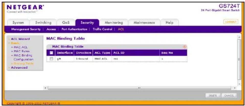
The following table describes the information displayed in the MAC Binding Table.
| Field Description | |
| Interface Displays the interface to which the MAC ACL is bound. | |
| Direction | Specifies the packet filtering direction for ACL. The only valid direction is Inbound, which means the MAC ACL rules are applied to traffic entering the port. |
| ACL Type Displays the type of ACL assigned to selected interface and direction. | |
| ACL ID Displays the ACL Name identifying the ACL assigned to selected interface and direction. | |
| Sequence No | Displays the Sequence Number signifying the order of specified ACL relative to other ACLs assigned to selected interface and direction. |
To delete a MAC ACL-to-interface binding, select the check box next to the interface and click Delete.
IP ACL
IP ACLs allow network managers to define classification actions and rules for specific ingress ports. Packets can be filtered on ingress (inbound) ports only. If the filter rules match, then some actions can be taken, including dropping the packet or disabling the port. For example, a network administrator defines an ACL rule that says port number 20 can receive TCP packets. However, if a UDP packet is received the packet is dropped.
ACLs are composed of access control entries (ACE), or rules, that consist of the filters that determine traffic classifications.
Use the IP ACL Configuration page to add or remove IP-based ACLs.
To display the IP ACL page, click Security > ACL, then click the Advanced > IP ACL link.
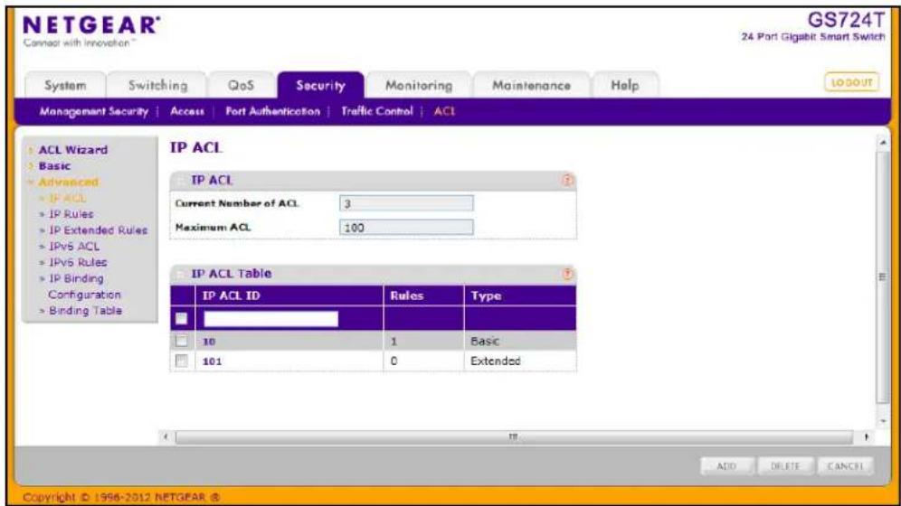
The IP ACL area shows the current size of the ACL table versus the maximum size of the ACL table. The current size is equal to the number of configured IPv4 plus the number of configured MAC ACLs. The maximum size is 100.
To configure an IP ACL:
- In the IP ACL ID field, specify the ACL ID. The ID is an integer in the following range:
• 1–99: Creates an IP Standard ACL, which allows you to permit or deny traffic from a source IP address.
- 100–199: Creates an IP Extended ACL, which allows you to permit or deny specific types of layer 3 or layer 4 traffic from a source IP address to a destination IP address. This type of ACL provides more granularity and filtering capabilities than the standard IP ACL.
Each configured ACL displays the following information:
- Rules. Displays the number of rules currently configured for the IP ACL.
• Type. Identifies the ACL as either a standard or extended IP ACL.
- To delete an IP ACL, select the check box next to the IP ACL ID field, then click Delete.
- To change the name of an IP ACL, select the check box next to the IP ACL ID field, update the name, then click Apply.
- Click Cancel to cancel the configuration on the screen and reset the data on the screen to the latest value of the switch.
Note: To configure a rule for an existing IP ACL, click its ID in the IP ACL Table. The IP ACL ID is a hyperlink to the rule configuration page for the ACL type.
IP Rules
Use the IP Rules page to define rules for IP-based standard ACLs. The access list definition includes rules that specify whether traffic matching the criteria is forwarded normally or discarded.
Note: There is an implicit “deny all” rule at the end of an ACL list. This means that if an ACL is applied to a packet and if none of the explicit rules match, then the final implicit “deny all” rule applies and the packet is dropped.
To display the IP Rules page, click Security > ACL, then click the Advanced > IP Rules link.
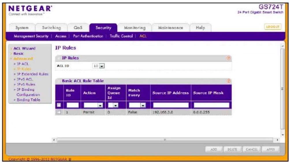
To configure rules for an IP ACL:
-
To add an IP ACL rule, select the ACL ID to add the rule to, complete the fields described in the following list, and click Add.
-
Rule ID. Specify a number from 1–10 to identify the IP ACL rule. You can create up to 10 rules for each ACL.
• Action. Selects the ACL forwarding action, which is one of the following: - Permit. Forwards packets which meet the ACL criteria.
- Deny. Drops packets which meet the ACL criteria.
- Assign Queue ID. Specifies the hardware egress queue identifier used to handle all packets matching this ACL rule. Enter an identifying number from 0–7 in the appropriate field.
- Match Every. Requires a packet to match the criteria of this ACL. Select True or False from the drop down menu. Match Every is exclusive to the other filtering rules, so if Match Every is True, the other rules on the screen are not available.
- Source IP Address. Requires a packet's source IP address to match the address listed here. Type an IP Address in the appropriate field using dotted-decimal notation. The address you enter is compared to a packet's source IP Address.
- Source IP Mask. Specifies the source IP address wildcard mask. Wild card masks determines which bits are used and which bits are ignored. A wild card mask of 255.255.255.255 indicates that no bit is important. A wildcard of 0.0.0.0 indicates that all of the bits are important. Wildcard masking for ACLs operates differently from a subnet mask. A wildcard mask is in essence the inverse of a subnet mask. For example, to apply the rule to all hosts in the 192.168.1.0/24 subnet, you type 0.0.0.255 in the Source IP Mask field. This field is required when you configure a source IP address.
-
To delete an IP ACL rule, select the check box associated with the rule, and then click Delete.
-
To update an IP ACL rule, select the check box associated with the rule, update the desired fields, and then click Apply. You cannot modify the Rule ID of an existing IP rule.
-
Click Cancel to cancel the configuration on the screen and reset the data on the screen to the latest value of the switch.
-
If you change any of the settings on the page, click Apply to send the updated configuration to the switch. Configuration changes take effect immediately.
IP Extended Rules
Use the IP Extended Rules page to define rules for IP-based extended ACLs. The access list definition includes rules that specify whether traffic matching the criteria is forwarded normally or discarded.
Note: There is an implicit “deny all” rule at the end of an ACL list. This means that if an ACL is applied to a packet and if none of the explicit rules match, then the final implicit “deny all” rule applies and the packet is dropped.
To display the IP extended Rules page, click Security > ACL, then click the Advanced > IP Extended Rules link. In the following figure, an extended IP ACL exists, and one rule has been configured.
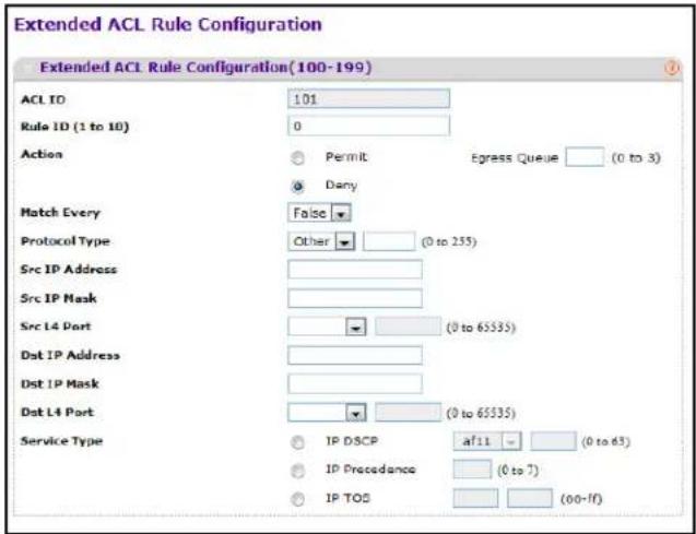
To configure rules for an IP ACL:
- To add an IP ACL rule, select the ACL ID to add the rule to, select the check box in the Extended ACL Rule table, and click Add. The page displays the extended ACL Rule Configuration fields.
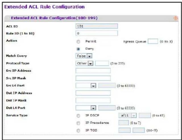
-
Configure the new rule.
-
Rule ID. Specify a number from 1–10 to identify the IP ACL rule. You can create up to 10 rules for each ACL.
• Action. Selects the ACL forwarding action, which is one of the following:
- Permit. Forwards packets which meet the ACL criteria.
- Deny. Drops packets which meet the ACL criteria.
- Egress Queue. Specifies the hardware egress queue identifier used to handle all packets matching this ACL rule. Enter an identifying number from 0–7 in the appropriate field.
- Match Every. Requires a packet to match the criteria of this ACL. Select True or False from the drop down menu. Match Every is exclusive to the other filtering rules, so if Match Every is True, the other rules on the screen are not available.
- Protocol Type. Requires a packet's protocol to match the protocol listed here. Select a type from the drop down menu or enter the protocol number in the available field.
- Src IP Address. Requires a packet's source IP address to match the address listed here. Type an IP Address in the appropriate field using dotted-decimal notation. The address you enter is compared to a packet's source IP Address.
- Src IP Mask. Specifies the source IP address wildcard mask. Wild card masks determines which bits are used and which bits are ignored. A wild card mask of 255.255.255.255 indicates that no bit is important. A wildcard of 0.0.0.0 indicates that all of the bits are important. Wildcard masking for ACLs operates differently from a subnet mask. A wildcard mask is in essence the inverse of a subnet mask. For example, to apply the rule to all hosts in the 192.168.1.0/24 subnet, you type 0.0.0.255 in the Source IP Mask field. This field is required when you configure a source IP address.
- Src L4 Port. Requires a packet's TCP/UDP source port to match the port listed here. Click Complete one of the following fields:
- Source L4 Keyword: Select the desired L4 keyword from a list of source ports on which the rule can be based.
-
Source L4 Port Number: If the source L4 keyword is Other, enter a user-defined Port ID by which packets are matched to the rule.
-
Dst IP Address. Requires a packet's destination port IP address to match the address listed here. Enter an IP Address in the appropriate field using dotted-decimal notation. The address you enter is compared to a packet's destination IP Address.
- Dst IP Mask. Specifies the destination IP address wildcard mask. Wild card masks determines which bits are used and which bits are ignored. A wild card mask of 255.255.255.255 indicates that no bit is important. A wildcard of 0.0.0.0 indicates that all of the bits are important. Wildcard masking for ACLs operates differently from a subnet mask. A wildcard mask is in essence the inverse of a subnet mask. For example, to apply the rule to all hosts in the 192.168.1.0/24 subnet, you type 0.0.0.255 in the Source IP Mask field. This field is required when you configure a source IP address.
-
Dst L4 Port. Requires a packet's TCP/UDP destination port to match the port listed here. Complete one of the following fields:
-
Destination L4 Keyword: Select the desired L4 keyword from a list of destination ports on which the rule can be based.
- Destination L4 Port Number: If the destination L4 keyword is Other, enter a user-defined Port ID by which packets are matched to the rule.
- Service Type. Choose one of the Service Type match conditions for the extended IP ACL rule. The possible values are IP DSCP, IP precedence, and IP TOS, which are alternative ways of specifying a match criterion for the same Service Type field in the IP header, however each uses a different user notation. After you select the service type, specify the value associated with the type.
- IP DSCP: Specify the IP DiffServ Code Point (DSCP) value. The DSCP is defined as the high-order six bits of the Service Type octet in the IP header. Select an IP DSCP value from the menu. To specify a numeric value in the available field, select Other from the menu and type an integer from 0 to 63 in the field.
- IP Precedence: The IP Precedence field in a packet is defined as the high-order three bits of the Service Type octet in the IP header. This is an optional configuration. Enter an integer from 0 to 7.
-
IP TOS Bits: Matches on the Type of Service bits in the IP header when checked. In the first TOS field, specify the two-digit hexadecimal TOS number. The second field is for the TOS Mask, which specifies the bit positions that are used for comparison against the IP TOS field in a packet. The TOS Mask value is a two-digit hexadecimal number from 00 to ff, representing an inverted (i.e., wildcard) mask. The zero-valued bits in the TOS Mask denote the bit positions in the TOS Bits value that are used for comparison against the IP TOS field of a packet. For example, to check for an IP TOS value having bits 7 and 5 set and bit 1 clear, where bit 7 is most significant, use a TOS Bits value of a0 and a TOS Mask of 00.
-
To delete an IP ACL rule, select the check box associated with the rule, and then click Delete.
- Click Cancel to cancel the configuration on the screen and reset the data on the screen to the latest value of the switch.
- To modify an existing IP Extended ACL rule, click the Rule ID. The number is a hyperlink to the Extended ACL Rule Configuration page. If the rule is Deny, you can specify the CPU Notification Mode.
- Enable. No power is supplied to the port.
- Disable. When a packet matches the ACL rule, the CPU is not notified, and the port continues to provide power.
- If you modify the rule, click Apply to submit the changes to the switch.
IPv6 ACL
An IPv6 ACL consists of a set of rules which are matched sequentially against a packet. When a packet meets the match criteria of a rule, the specified rule action (Permit/Deny) is taken and the additional rules are not checked for a match. On this menu, the interfaces to which an IP ACL applies must be specified, as well as whether it applies to inbound or outbound traffic. Rules for the IP ACL are specified/created using the IP ACL Rule Configuration menu.
To display the IPv6 ACL page, click Security > ACL > Advanced > IPv6 ACL.
The current number of the IP ACLs configured on the switch is displayed in the Current Number of ACL area. The maximum number of IP ACL that can be configured on the switch is displayed in the Maximum ACL field, depending on the hardware. The name of IPv6 ACL can be configured in IPv6 ACL field. The number of the rules associated with the IP ACL is displayed in the Rules field. The ACL type is IPv6 ACL and displayed in the Type field.
To create an IPv6 ACL:
- To add an ACL, type a name in the IPv6 ACL field, and then click Add.
- To delete an ACL, select the check box associated with the ACL, and then click Delete.
- Click Cancel to cancel the configuration on the screen and reset the data on the screen to the latest value of the switch.
- If you modify the IPv6 ACL name, click Apply to submit the changes to the switch.
IPv6 Rules
Use the IPv6 Rules page to configure the rules for the IPv6 Access Control Lists. The IPv6 Access Control Lists are created using the IPv6 Access Control List Configuration page. By default, no specific value is in effect for any of the IPv6 ACL rules.
To display the IPv6 Rules page, click Security > ACL > Advanced > IPv6 Rules. In the following figure, an IPv6 rule exists, and one rule has been configured.
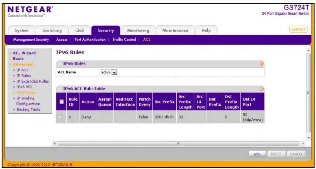
To configure the IPv6 rules, select the following:
- To add an IPv6 rule, use the pull-down list in the ACL Name field to select the IP ACL for which to create or update a rule. Complete the fields described in the following list, and click Add.
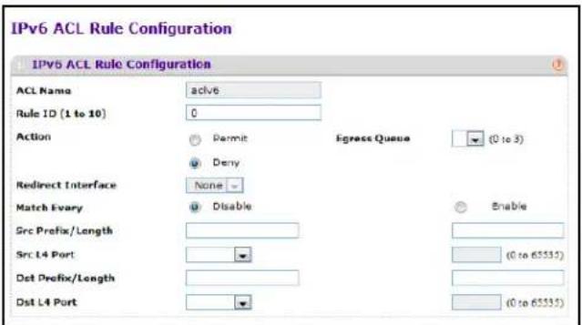
- Configure the new rule.
- Rule ID: Enter a whole number in the range of 1 to 10 that will be used to identify the rule. An IPv6 ACL may have up to 10 rules.
- Action: Specify what action should be taken if a packet matches the rule's criteria. The choices are Permit or Deny.
- Egress Queue: Specifies the hardware egress queue identifier used to handle all packets matching this IPv6 ACL rule. The valid range of Queue IDs is from 0 to 6. This field is visible for a Permit Action.
- Redirect Interface: Specifies the egress interface where the matching traffic stream is forced, bypassing any forwarding decision normally performed by the device. This field is visible for a Permit action and cannot be set if a Mirror Interface is already configured for the ACL rule. Redirected interfaces should be part of the traffic VLAN.
- Match Every: Select true or false from the pull down menu. True signifies that all packets will match the selected IPv6 ACL and Rule and will be either permitted or denied. In this case, since all packets match the rule, the option of configuring other match criteria will not be offered. To configure specific match criteria for the rule, remove the rule and recreate it, or reconfigure Match Every to False for the other match criteria to be visible.
- Source Prefix/Prefix Length: Specify IPv6 Prefix combined with IPv6 Prefix length of the network or host from which the packet is being sent. Prefix length can be in the range (0 to 128).
- Source L4 Port: Specify a packet's source layer 4 port as a match condition for the selected IPv6 ACL rule. Source port information is optional. Source port information can be specified in two ways:
- Select keyword "other" from the drop-down menu and specify the number of the port in the range from 0 to 65535.
- Select one of the keyword from the list: DOMAIN, ECHO, FTP, FTPDATA, HTTP, SMTP, SNMP, TELNET, TFTP, and WWW. Each of these values translates into its equivalent port number, which is used as both the start and end of the port range.
- Destination Prefix/Prefix Length: Enter up to 128-bit prefix combined with prefix length to be compared to a packet's destination IP Address as a match criteria for the selected IPv6 ACL rule. Prefix length can be in the range (0 to 128).
- Destination L4 Port: Specify a packet's destination layer 4 port as a match condition for the selected IPv6 ACL rule. Destination port information is optional. Destination port information can be specified in two ways:
- Select keyword "other" from the drop-down menu and specify the number of the port in the range from 0 to 65535.
-
Select one of the keyword from the list: DOMAIN, ECHO, FTP, FTPDATA, HTTP, SMTP, SNMP, TELNET, TFTP, and WWW. Each of these values translates into its equivalent port number, which is used as both the start and end of the port range.
-
Click Cancel to cancel the configuration on the screen and reset the data on the screen to the latest value of the switch.
- To add the new rule to the ACL, click Apply.
- To delete a rule from an ACL, select the check box associated with the rule and click Delete.
IP Binding Configuration
When an ACL is bound to an interface, all the rules that have been defined are applied to the selected interface. Use the IP Binding Configuration page to assign IPv4 and IPv6 ACLs to ports and LAGs. From this page, you can also assign a sequence number to the ACLs that are bound to interfaces, which determines the priority of the ACLs when an interface is associated with more than one.
To display the IP Binding Configuration page, click Security > ACL, then click the Advanced > IP Binding Configuration link.
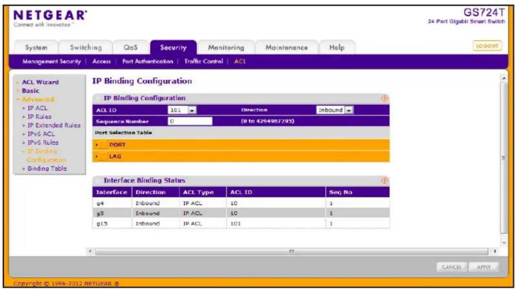
To configure IP ACL interface bindings:
- Select an existing IP ACL from the ACL ID menu.
The packet filtering direction for ACL is Inbound, which means the IP ACL rules are applied to traffic entering the port.
- Specify an optional sequence number to indicate the order of this access list relative to other access lists already assigned to this interface and direction.
A low number indicates high precedence order. If a sequence number is already in use for this interface and direction, the specified access list replaces the currently attached access list using that sequence number. If the sequence number is not specified by the user, a sequence number that is one greater than the highest sequence number currently in use for this interface and direction will be used. The valid range is 1–4294967295.
- Click the appropriate orange bar to expose the available ports or LAGs.
- To add the selected ACL to a port or LAG, click the box directly below the port or LAG number so that an X appears in the box.
• To remove the selected ACL from a port or LAG, click the box directly below the port or LAG number to clear the selection. An X in the box indicates that the ACL is applied to the interface.
-
Click Cancel to cancel the configuration on the screen and reset the data on the screen to the latest value of the switch.
-
Click Apply to save any changes to the running configuration.
IP Binding Table
Use the IP Binding Table page to view or delete the IP ACL bindings.
To display the IP Binding Table, click Security > ACL, then click the Advanced > Binding Table link.
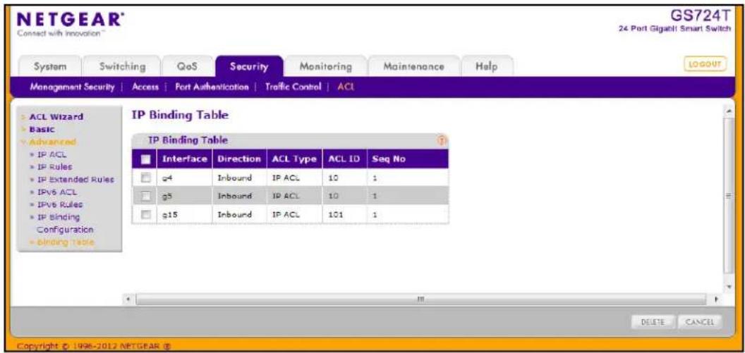
The following table describes the information displayed in the MAC Binding Table.
| Field Description | |
| Interface Displays the interface to which the IP ACL is bound. | |
| Direction Specifies the packet filtering direction for ACL. The only valid direction is Inbound, which means the IP ACL rules are applied to traffic entering the port. | |
| ACL Type Displays the type of ACL assigned to selected interface and direction. | |
| ACL ID Displays the ACL Number identifying the ACL assigned to selected interface and direction. | |
| Seq No. Displays the Sequence Number signifying the order of specified ACL relative to other ACLs assigned to selected interface and direction. | |
To delete an IP ACL-to-interface binding, select the check box next to the interface and click Delete.
Use the features available from the Monitoring tab to view a variety of information about the switch and its ports and to configure how the switch monitors events. The Monitoring tab contains links to the following features:
- Ports on page 229
• System Logs on page 241
• Port Mirroring on page 250
Ports
The pages available from the Ports link contain a variety of information about the number and type of traffic transmitted from and received on the switch. From the Ports link, you can access the following pages:
- Switch Statistics on page 229
• Port Statistics on page 232
• Port Detailed Statistics on page 233
• EAP Statistics on page 240
Switch Statistics
The Switch Statistics page displays detailed statistical information about the traffic the switch handles.
To access the Switch Statistics page, click Monitoring >Ports >Switch Statistics.
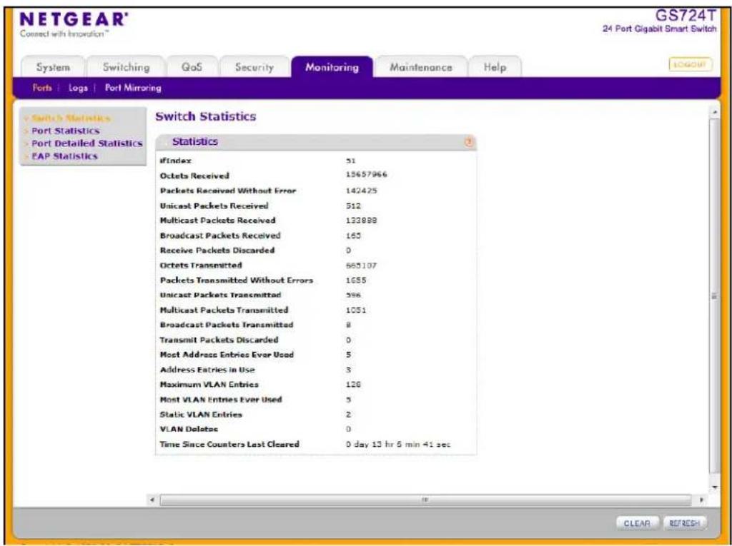
The following table describes the Switch Statistics displayed on the screen.
| Field Description | |
| ifIndex This object indicates the | ifIndex of the interface table entry associated with the processor of this switch. |
| Octets Received The total num | ber of octets of data received by the processor (excluding framing bits, but including FCS octets). |
| Packets Received Without Errors | The total number of packets (including broadcast packets and multicast packets) received by the processor. |
| Unicast Packets Received The | number of subnetwork-unicast packets delivered to a higher layer protocol. |
| Multicast Packets Received The | the total number of packets received that were directed to a multicast address. This number does not include packets directed to the broadcast address. |
| Broadcast Packets Received The | the total number of packets received that were directed to the broadcast address. This does not include multicast packets. |
| Receive Packets Discarded The | the number of inbound packets which were chosen to be discarded, even though no errors had been detected, in order to prevent their being delivered to a higher layer protocol. A possible reason for discarding a packet could be to free up buffer space. |
| Octets Transmitted | The total number of octets transmitted out of the interface, including framing characters. |
| Packets Transmitted Without Errors | The total number of packets transmitted out of the interface. |
| Unicast Packets Transmitted | The total number of packets that higher level protocols requested be transmitted to a subnetwork-unicast address, including those that were discarded or not sent. |
| Multicast Packets Transmitted | The total number of packets that higher level protocols requested be transmitted to a Multicast address, including those that were discarded or not sent. |
| Broadcast Packets Transmitted | The total number of packets that higher-level protocols requested be transmitted to the Broadcast address, including those that were discarded or not sent. |
| Transmit Packets Discarded | The number of outbound packets which were chosen to be discarded, even though no errors had been detected, in order to prevent their being delivered to a higher layer protocol. A possible reason for discarding a packet could be to free up buffer space. |
| Most Address Entries Ever Used | The highest number of Forwarding Database Address Table entries that have been learned by this switch since the most recent reboot. |
| Address Entries in Use The num | number of Learned and static entries in the Forwarding Database Address Table for this switch. |
| Maximum VLAN Entries The m | maximum number of Virtual LANs (VLANs) allowed on this switch. |
| Most VLAN Entries Ever Used | The largest number of VLANs that have been active on this switch since the last reboot. |
| Static VLAN Entries The num | ber of presently active VLAN entries on this switch that have been created statically. |
| Dynamic VLAN Entries The nu | number of presently active VLAN entries on this switch. |
| VLAN Deletes The number of | VLANs on this switch that have been created and then deleted since the last reboot. |
| Time Since Counters Last Cleared | The elapsed time, in days, hours, minutes, and seconds, since the statistics for this switch were last cleared. |
Use the buttons at the bottom of the page to perform the following actions:
- Click Clear to clear all the statistics counters, resetting all switch summary and detailed statistics to default values. The discarded packets count cannot be cleared.
- Click Refresh to refresh the page with the most current data from the switch.
Port Statistics
The Port Statistics page displays a summary of per-port traffic statistics on the switch.
To access the Port Summary page, click Monitoring >Ports tab, and then click the Port Statistics link.
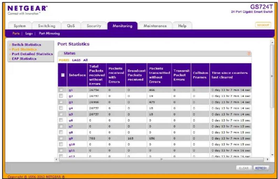
To view port statistics:
- To view statistics for the physical ports, click PORTS. Click the interface ID to view detailed statistics for the port.
- To view statistics for the Link Aggregation Groups (LAGs), click LAGS. Click the LAG ID to view detailed statistics for the port
The following table describes the per-port statistics displayed on the screen.
| Field Description | |
| Interface Lists the ports on the | system. |
| Total Packets Received Without Errors | The total number of packets received that were without errors. |
| Packets Received With Error | The number of inbound packets that contained errors preventing them from being deliverable to a higher layer protocol. |
| Broadcast Packets Received | The total number of good packets received that were directed to the broadcast address. This does not include multicast packets. |
| Packets Transmitted Without Errors | The number of frames that have been transmitted by this port to its segment. |
| Transmit Packet Errors The number of outbound packets that could not be transmitted because of errors. | |
| Collision Frames The best estimate of the total number of collisions on this Ethernet segment. | |
| Time Since Counters Last Cleared | The elapsed time, in days, hours, minutes, and seconds since the statistics for this port were last cleared. |
Use the buttons at the bottom of the page to perform the following actions:
- To clear all the counters for all ports on the switch, select the check box in the row heading and click Clear. The button resets all statistics for all ports to default values.
- To clear the counters for a specific port, select the check box associated with the port and click Clear.
- Click Refresh to refresh the data on the screen and display the most current statistics.
Port Detailed Statistics
The Port Detailed Statistics page displays a variety of per-port traffic statistics.
To access the Port Detailed page, click the Monitoring >Ports tab, and then click Port Detailed Statistics. (The Port Detailed Statistics figure shows some, but not all, of the fields on the page.)
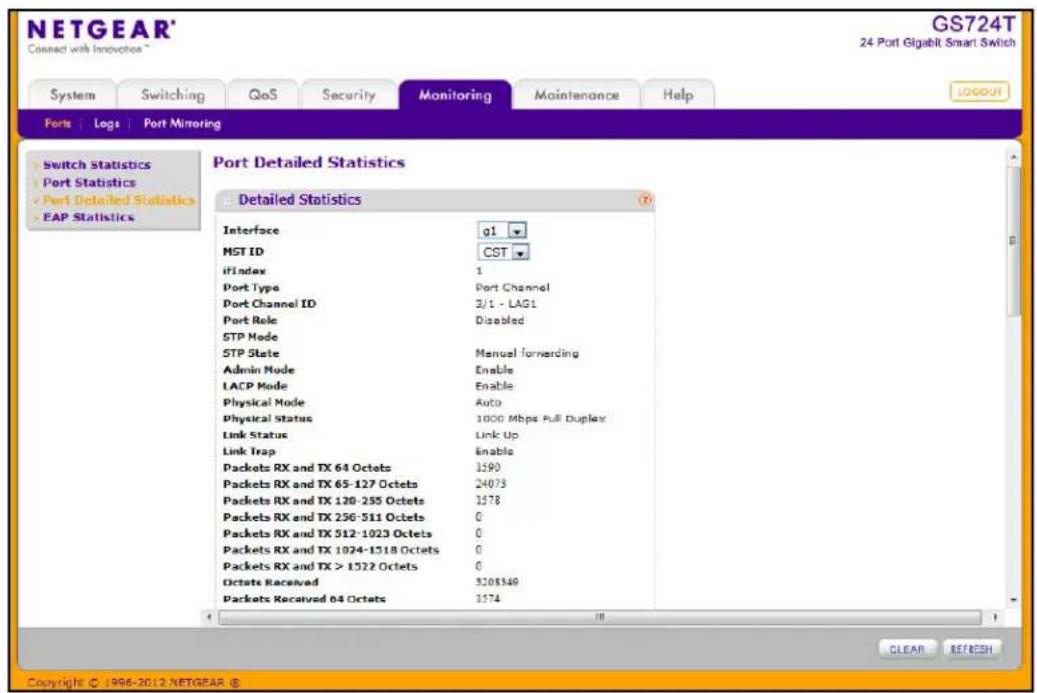
The following table describes the detailed port information displayed on the screen. To view information about a different port, select the port number from the Interface menu.
| Field Description | |
| Interface Use the drop down | menu to select the interface for which data is to be displayed or configured. |
| MST ID Displays the created | or existing MSTs. |
| ifIndex This field indicates the | ifIndex of the interface table entry associated with this port on an adapter. |
| Port Type For most ports this | field is blank. Otherwise the possible values are: Mirrored: Indicates that the port has been configured as a monitoring port and is the source port in a port mirroring session. For additional information about port monitoring and probe ports, see Multiple Port Mirroring on page 250. Probe: Indicates that the port has been configured as a monitoring port and is the destination port in a port mirroring session. For additional information about port monitoring and probe ports, see Multiple Port Mirroring on page 250. Port Channel: Indicates that the port has been configured as a member of a port-channel, which is also known as a link Aggregation Group (LAG). |
| Port Channel ID If the port is | a member of a port channel, the port channel's interface ID and name are shown. Otherwise, Disable is shown. |
| Port Role Each MST Bridge | Port that is enabled is assigned a Port Role for each spanning tree. The port role will be one of the following values: Root Port, Designated Port, Alternate Port, Backup Port, Master Port, or Disabled Port. |
| STP Mode Displays the Spanning Tree Protocol (STP) Administrative Mode for the port or LAG. The possible values for this field are: Enable: Enables the Spanning Tree Protocol for this port. Disable: Disables the Spanning Tree Protocol for this port. | |
| STP State | Displays the port's current state Spanning Tree state. This state controls what action a port takes on receipt of a frame. If the bridge detects a malfunctioning port it will place that port into the broken state. The other five states are defined in IEEE 802.1D: Disabled Blocking Listening Learning Forwarding Broken |
| Admin Mode Displays the port control administration state: Enable: The port can participate in the network (default). Disable: The port is administratively down and does not participate in the network. | |
| LACP Mode Selects the Link | Aggregation Control Protocol administration state:Enable: Specifies that the port is allowed to participate in a port channel (LAG), which is the default mode.Disable: Specifies that the port cannot participate in a port channel (LAG). |
| Physical Mode Indicates the | port speed and duplex mode. In auto-negotiation mode, the duplex mode and speed are set from the auto-negotiation process. |
| Physical Status Indicates the | port speed and duplex mode status. |
| Link Status Indicates whether | the link is up or down. |
| Link Trap This object determines whether or not to send a trap when link status changes. The factory default is Enable.Enable: Specifies that the system sends a trap when the link status changes.Disable: Specifies that the system does not send a trap when the link status changes. | |
| Packets RX and TX 64 Octets | The total number of packets (including bad packets) received or transmitted that were 64 octets in length (excluding framing bits but including FCS octets). |
| Packets RX and TX 65-127 Octets | The total number of packets (including bad packets) received or transmitted that were between 65 and 127 octets in length inclusive (excluding framing bits but including FCS octets). |
| Packets RX and TX 128-255 Octets | The total number of packets (including bad packets) received or transmitted that were between 128 and 255 octets in length inclusive (excluding framing bits but including FCS octets). |
| Packets RX and TX 256-511 Octets | The total number of packets (including bad packets) received or transmitted that were between 256 and 511 octets in length inclusive (excluding framing bits but including FCS octets). |
| Packets RX and TX 512-1023 Octets | The total number of packets (including bad packets) received or transmitted that were between 512 and 1023 octets in length inclusive (excluding framing bits but including FCS octets). |
| Packets RX and TX 1024-1518 Octets | The total number of packets (including bad packets) received or transmitted that were between 1024 and 1518 octets in length inclusive (excluding framing bits but including FCS octets). |
| Packets RX and TX >1522 Octets | The total number of packets (including bad packets) received or transmitted that are in excess of 1522 octets in length inclusive (excluding framing bits but including FCS octets). |
| Octets Received | The total number of octets of data (including those in bad packets) received on the network (excluding framing bits but including FCS octets). This object can be used as a reasonable estimate of ethernet utilization. If greater precision is desired, the etherStatsPkts and etherStatsOctets objects should be sampled before and after a common interval. |
| Packets Received 64 Octets | The total number of packets (including bad packets) received that were 64 octets in length (excluding framing bits but including FCS octets). |
| Packets Received 65-127 Octets | The total number of packets (including bad packets) received that were between 65 and 127 octets in length inclusive (excluding framing bits but including FCS octets). |
| Packets Received 128-255 Octets | The total number of packets (including bad packets) received that were between 128 and 255 octets in length inclusive (excluding framing bits but including FCS octets). |
| Packets Received 256-511 Octets | The total number of packets (including bad packets) received that were between 256 and 511 octets in length inclusive (excluding framing bits but including FCS octets). |
| Packets Received 512-1023 Octets | The total number of packets (including bad packets) received that were between 512 and 1023 octets in length inclusive (excluding framing bits but including FCS octets). |
| Packets Received 1024-1518 Octets | The total number of packets (including bad packets) received that were between 1024 and 1518 octets in length inclusive (excluding framing bits but including FCS octets). |
| Packets Received > 1522 Octets | The total number of packets received that were in excess of 1522 octets (excluding framing bits, but including FCS octets) and were otherwise well formed. |
| Total Packets Received Without Errors | The total number of packets received that were without errors. |
| Unicast Packets Received The | the number of subnetwork-unicast packets delivered to a higher-layer protocol. |
| Multicast Packets Received The | The total number of good packets received that were directed to a multicast address. This number does not include packets directed to the broadcast address. |
| Broadcast Packets Received | The total number of good packets received that were directed to the broadcast address. This does not include multicast packets. |
| Total Packets Received with MAC Errors | The total number of inbound packets that contained errors preventing them from being deliverable to a higher-layer protocol. |
| Jabbers Received The total | number of packets received that were longer than 1518 octets (excluding framing bits, but including FCS octets), and had either a bad Frame Check Sequence (FCS) with an integral number of octets (FCS Error) or a bad FCS with a non-integral number of octets (Alignment Error). This definition of jabber is different than the definition in IEEE2.3 section 8.2.1.5 (10BASE5) and section 10.3.1.4 (10BASE2). These documents define jabber as the condition where any packet exceeds 20 ms. The allowed range to detect jabber is between 20 ms and 150 ms. |
| Fragments Received The total | number of packets received that were less than 64 octets in length with ERROR CRC (excluding framing bits but including FCS octets). |
| Undersize Received The total | number of packets received that were less than 64 octets in length with GOOD CRC (excluding framing bits but including FCS octets). |
| Alignment Errors | The total number of packets received that had a length (excluding framing bits, but including FCS octets) of between 64 and 1518 octets, inclusive, but had a bad Frame Check Sequence (FCS) with a non-integral number of octets. |
| Rx FCS Errors The total num | ber of packets received that had a length (excluding framing bits, but including FCS octets) of between 64 and 1518 octets, inclusive, but had a bad Frame Check Sequence (FCS) with an integral number of octets |
| Overruns The total number of | frames discarded as this port was overloaded with incoming packets, and could not keep up with the inflow. |
| Total Received Packets Not Forwarded | A count of valid frames received which were discarded (i.e., filtered) by the forwarding process. |
| Local Traffic Frames The total | number of frames dropped in the forwarding process because the destination address was located off of this port. |
| 802.3x Pause Frames Received | A count of MAC Control frames received on this interface with an opcode indicating the PAUSE operation. This counter does not increment when the interface is operating in half-duplex mode. |
| Unacceptable Frame Type | The number of frames discarded from this port due to being an unacceptable frame type. |
| Multicast Tree Viable Discards | The number of frames discarded when a lookup in the multicast tree for a VLAN occurs while that tree is being modified. |
| Reserved Address Discards | The number of frames discarded that are destined to an IEEE 802.1 reserved address and are not supported by the system. |
| Broadcast Storm Recovery T | the number of frames discarded that are destined for FF:FF:FF:FF:FF:FF when Broadcast Storm Recovery is enabled. |
| CFI Discards The number of | frames discarded that have CFI bit set and the addresses in RIF are in non-canonical format. |
| Upstream Threshold | The number of frames discarded due to lack of cell descriptors available for that packet's priority level. |
| Total Packets Transmitted (Octets) | The total number of octets of data (including those in bad packets) transmitted on the network (excluding framing bits but including FCS octets). This object can be used as a reasonable estimate of ethernet utilization. If greater precision is desired, the etherStatsPkts and etherStatsOctets objects should be sampled before and after a common interval. |
| Packets Transmitted 64 Octets | The total number of packets (including bad packets) transmitted that were 64 octets in length (excluding framing bits but including FCS octets). |
| Packets Transmitted 65-127 Octets | The total number of packets (including bad packets) transmitted that were between 65 and 127 octets in length inclusive (excluding framing bits but including FCS octets). |
| Packets Transmitted 128-255 Octets | The total number of packets (including bad packets) transmitted that were between 128 and 255 octets in length inclusive (excluding framing bits but including FCS octets). |
| Packets Transmitted 256-511 Octets | The total number of packets (including bad packets) transmitted that were between 256 and 511 octets in length inclusive (excluding framing bits but including FCS octets). |
| Packets Transmitted 512-1023 Octets | The total number of packets (including bad packets) transmitted that were between 512 and 1023 octets in length inclusive (excluding framing bits but including FCS octets). |
| Packets Transmitted 1024-1518 Octets | The total number of packets (including bad packets) transmitted that were between 1024 and 1518 octets in length inclusive (excluding framing bits but including FCS octets). |
| Packets Transmitted 1519-1522 Octets | The total number of packets (including bad packets) transmitted that were between 1519 and 1522 octets in length inclusive (excluding framing bits but including FCS octets). |
| Total Packets Transmitted Successfully | The number of frames that have been transmitted by this port to its segment. |
| Unicast Packets Transmitted | The total number of packets that higher-level protocols requested be transmitted to a subnetwork-unicast address, including those that were discarded or not sent. |
| Multicast Packets Transmitted | The total number of packets that higher-level protocols requested be transmitted to a Multicast address, including those that were discarded or not sent. |
| Broadcast Packets Transmitted | The total number of packets that higher-level protocols requested be transmitted to the Broadcast address, including those that were discarded or not sent. |
| Total Transmit Errors The sum of Single, Multiple, and Excessive Collisions. | |
| Tx FCS Errors The total number of packets transmitted that had a length (excluding framing bits, but including FCS octets) of between 64 and 1518 octets, inclusive, but had a bad Frame Check Sequence (FCS) with an integral number of octets | |
| Tx Oversized The total number of frames that exceeded the max permitted frame size. This counter has a max increment rate of 815 counts per second at 10 Mb/s. | |
| Underrun Errors The total number of frames discarded because the transmit FIFO buffer became empty during frame transmission. | |
| Total Transmit Packets Discarded | The sum of single collision frames discarded, multiple collision frames discarded, and excessive frames discarded. |
| Single Collision Frames A count of the number of successfully transmitted frames on a particular interface for which transmission is inhibited by exactly one collision. | |
| Multiple Collision Frames A count of the number of successfully transmitted frames on a particular interface for which transmission is inhibited by more than one collision. | |
| Excessive Collision Frames A count of frames for which transmission on a particular interface fails due to excessive collisions. | |
| Port Membership Discards | The number of frames discarded on egress for this port due to egress filtering being enabled. |
| STP BPDUs Received Number of STP BPDUs received at the selected port. | |
| STP BPDUs Transmitted Number of STP BPDUs transmitted from the selected port. | |
| RSTP BPDUs Received Number of RSTP BPDUs received at the selected port. | |
| RSTP BPDUs Transmitted Number of RSTP BPDUs transmitted from the selected port. | |
| MSTP BPDUs Received Number of MSTP BPDUs received at the selected port. | |
| MSTP BPDUs Transmitted Number of MSTP BPDUs transmitted from the selected port. | |
| 802.3x Pause Frames Transmitted | A count of MAC Control frames transmitted on this interface with an opcode indicating the PAUSE operation. This counter does not increment when the interface is operating in half-duplex mode. |
| EAPOL Frames Received The number of valid EAPOL frames of any type that have been received by this authenticator. | |
| EAPOL Frames Transmitted | The number of EAPOL frames of any type that have been transmitted by this authenticator. |
| Time Since Counters Last Cleared | The elapsed time, in days, hours, minutes, and seconds since the statistics for this port were last cleared. |
Use the buttons at the bottom of the page to perform the following actions:
- Click Clear to clear all the counters. This resets all statistics for this port to the default values.
- Click Refresh to refresh the data on the screen and display the most current statistics.
EAP Statistics
Use the EAP Statistics page to display information about EAP packets received on a specific port.
To display the EAP Statistics page, click the Monitoring >Ports tab, and then click the EAP Statistics link.
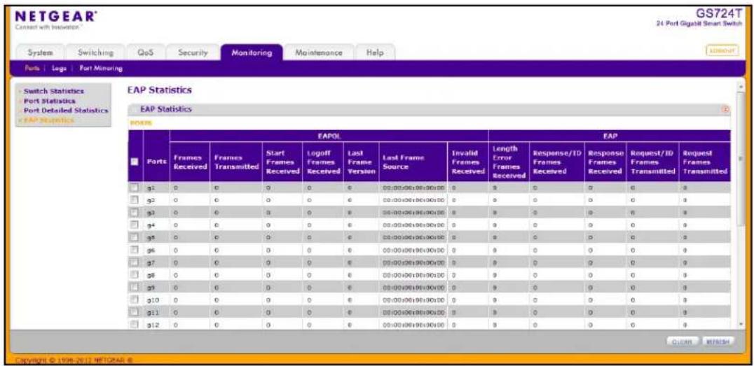
The following table describes the EAP statistics displayed on the screen.
| Field Description | |
| Ports Specifies the interface which is polled for statistics. | |
| Frames Received Displays the number of valid EAPOL frames received on the port. | |
| Frames Transmitted Displays the number of EAPOL frames transmitted through the port. | |
| Start Frames Received Displays the number of EAPOL Start frames received on the port. | |
| Logoff Frames Received Displays the number of EAPOL Log off frames that have been received on the port. | |
| Last Frame Version Displays the protocol version number attached to the most recently received EAPOL frame. | |
| Last Frame Source Displays the source MAC Address attached to the most recently received EAPOL frame. | |
| Invalid Frames Received Displays the number of unrecognized EAPOL frames received on this port. | |
| Length Error Frames Received Displays the number of EAPOL frames with an invalid Packet Body Length received on this port. | |
| Response/ID Frames Received | Displays the number of EAP Respond ID frames that have been received on the port. |
| Response Frames Received Displays the number of valid EAP Response frames received on the port. | |
| Request/ID Frames Transmitted | Displays the number of EAP Requested ID frames transmitted through the port. |
| Request Frames Transmitted | Displays the number of EAP Request frames transmitted through the port. |
Use the buttons at the bottom of the page to perform the following actions:
- To clear all the EAP counters for all ports on the switch, select the check box in the row heading and click Clear. The button resets all statistics for all ports to default values.
- To clear the counters for a specific port, select the check box associated with the port and click Clear.
- Click Refresh to refresh the data on the screen and display the most current statistics.
System Logs
The switch may generate messages in response to events, faults, or errors occurring on the platform as well as changes in configuration or other occurrences. These messages are stored locally and can be forwarded to one or more centralized points of collection for monitoring purposes or long term archival storage. Local and remote configuration of the logging capability includes filtering of messages logged or forwarded based on severity and generating component.
The Monitoring > Logs tab contains links to the following folders:
• Memory Logs on page 242
- FLASH Log Configuration on page 244
• Server Log Configuration on page 246
- Trap Logs on page 248
• Event Logs on page 249
Memory Logs
The in-memory log stores messages in memory based upon the settings for message component and severity. Use the Memory Logs page to set the administrative status and behavior of logs in the system buffer. These log messages are cleared when the switch reboots.
To access the Memory Log page, click the Monitoring > Logs tab, and then click the Memory Log link.
![NETGEAR® Connect with innovation™ GS716T 16 Port Gigabit Smart Switch System Switching QoS Security Monitoring Maintenance Help Ports | Logs | Port Mirroring Memory Logs - Memory Logs FLASH Logs Server Logs Trap Logs Event Logs Memory Logs Configuration Admin Status Disable Enable Behavior Wrap Memory Logs Total number of Messages 4739 (displaying only the last G4 messages) Description <13> Jan 03 07:49:10 10.27.233.160-1 TRAPNGR[2182254452]; traputilc(605) 4825 %% Link Down: g1 <13> Jan 03 07:49:10 10.27.233.160-1 TRAPNGR[2182254452]; traputilc(605) 4826 %% Link Down: g3 <13> Jan 03 07:49:10 10.27.233.160-1 TRAPNGR[2182254452]; traputilc(605) 4827 %% Link Down: g5 <13> Jan 03 07:49:12 10.27.233.160-1 TRAPNGR[2182254452]; traputilc(605) 4828 %% Link Up: g2 <13> Jan 03 07:49:12 10.27.233.160-1 TRAPNGR[2182254452] CLEAR REFRESH CANCEL APPLY Copyright © 1996-2012 NETGEAR ®](/content/2026/05/825774/images/df95028ce1ed828c20ecfa8d926c1fe3ca2fe5143afa9a84e3899721ef62e904.jpg)
To configure the Memory Log settings:
-
Use the radio buttons in the Admin Status field to determine whether to log messages.
-
Enable: Enables system logging.
-
Disable: Prevents the system from logging messages.
-
From the Behavior menu, specify the behavior of the log when it is full.
-
Wrap: When the buffer is full, the oldest log messages are deleted as the system logs new messages.
-
Stop on Full: When the buffer is full, the system stops logging new messages and preserves all existing log messages.
-
If you change the buffered log settings, click Apply to apply the changes to the system and the changes will be saved.
The Memory Log table also appears on the Memory Log page.
| Field Description | |
| Total Number of Messages Displays the number of messages the system has logged in memory. Only the 64 most recent entries are displayed on the page. | |
| Description The log message text, which includes the time the log was recorded. | |
The rest of the page displays the Memory Log messages. The format of the log message is the same for messages that are displayed for the message log, persistent log, or console log. Messages logged to a collector or relay via syslog have the same format as well.
The following example shows the standard format for a log message:
<14> Mar 24 05:34:05 10.131.12.183-1 UNKN[2176789276]: main_login.c(179) 3855 %% HTTP Session 19 initiated for user admin connected from 10.27.64.122
The number contained in the angle brackets represents the message priority, which is derived from the following values:
Priority = (facility value × 8) + severity level.
The facility value is usually one, which means it is a user-level message. Therefore, to determine the severity level of the message, subtract eight from the number in the angle brackets. The example log message has a severity level of 6 (informational). For more information about the severity of a log message, see the Severity Filter description on page 247.
The message was generated on March 24 at 5:34:05 a.m by the switch with an IP address of 10.131.12.183. The component that generated the message is unknown, but it came from line 179 of the main_login.c file. This is the 3,855^th message logged since the switch was last booted. The message indicates that the administrator logged onto the HTTP management interface from a host with an IP address of 10.27.64.122.
Use the buttons at the bottom of the page to perform the following actions:
- Click Clear to clear the messages out of the buffered log in the memory.
- Click Refresh to update the page with the latest messages in the log.
- Click Cancel to cancel the configuration on the screen and reset the data on the screen to the latest value of the switch.
FLASH Log Configuration
The FLASH log is a log that is stored in persistent storage, which means that the log messages are retained across a switch reboot.
- The first log type is the system startup log. The system startup log stores the first N messages received after system reboot. This log always has the log full operation attribute set to stop on full and can store up to 32 messages.
- The second log type is the system operation log. The system operation log stores the last N messages received during system operation. This log always has the log full operation attribute set to overwrite. This log can store up to 1000 messages.
Either the system startup log or the system operation log stores a message received by the log subsystem that meets the storage criteria, but not both. On system startup, if the startup log is configured, it stores messages up to its limit. The operation log, if configured, then begins to store the messages.
Use the FLASH Log Configuration page to enable or disable persistent logging and to set the severity filter.
To access the FLASH Log Configuration page, click the Monitoring > Logs tab, and then click the FLASH Log link.
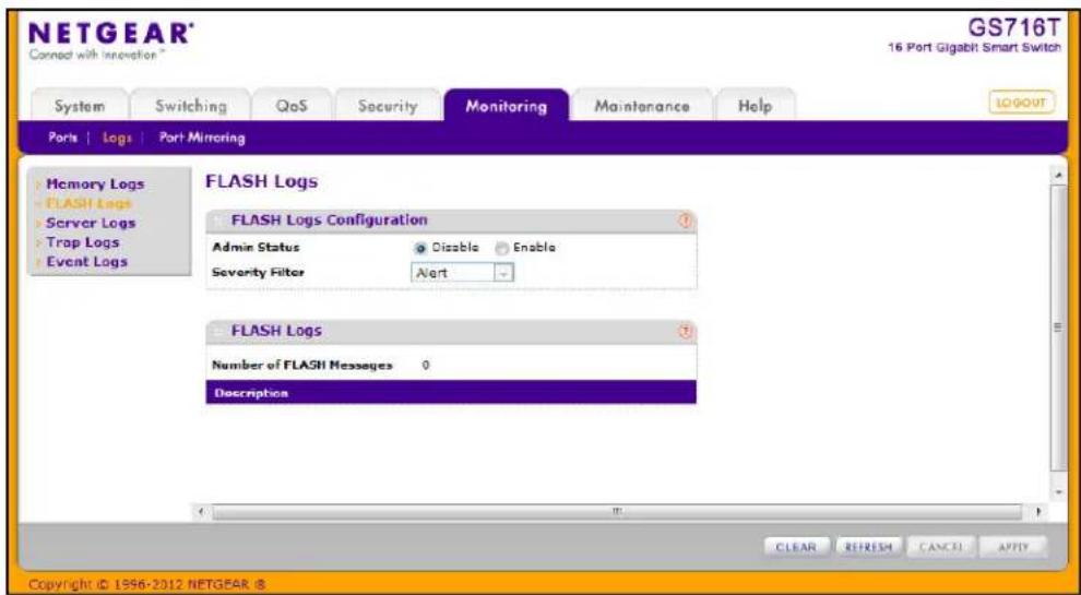
To configure the FLASH Log settings:
-
Use the radio buttons in the Admin Status field to determine whether to log messages to persistent storage.
-
Enable: Enables persistent logging.
-
Disable: Prevents the system from logging messages in persistent storage.
-
From the Severity Filter field, specify the type of log messages to record. A log records messages equal to or above a configured severity threshold. For example, if you select
Error, the logged messages include Error, Critical, Alert, and Emergency. The default severity level is Alert (1).
The severity can be one of the following levels:
- Emergency (0): The highest level warning level. If the device is down or not functioning properly, an emergency log is saved to the device.
- Alert (1): The second highest warning level. An alert log is saved if there is a serious device malfunction, such as all device features being down. Action must be taken immediately.
- Critical (2): The third highest warning level. A critical log is saved if a critical device malfunction occurs, for example, two device ports are not functioning, while the rest of the device ports remain functional.
- Error (3): A device error has occurred, such as if a port is offline.
- Warning (4): The lowest level of a device warning.
- Notice (5): Normal but significant conditions. Provides the network administrators with device information.
• Information (6): Provides device information. -
Debug (7): Provides detailed information about the log. Debugging should only be entered by qualified support personnel.
-
If you make any changes to the page, click Apply to apply the change to the system.
The rest of the page displays the number of persistent messages the system has logged and the persistent log messages.
Use the buttons at the bottom of the page to perform the following actions:
- Click Clear to clear the messages out of the buffered log.
- Click Refresh to refresh the page with the most current data from the switch.
- Click Cancel to cancel the configuration on the screen and reset the data on the screen to the latest value of the switch.
Server Log Configuration
Use the Server Log Configuration page to allow the switch to send log messages to the remote logging hosts configured on the system.
To access the Server Log Configuration page, click the Monitoring > Logs tab, and then click the Server Log link.
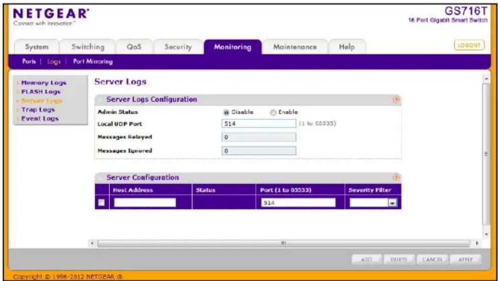
To configure local log server settings:
-
Use the radio buttons in the Admin Status field to determine whether to send log messages to the remote syslog hosts configured on the switch.
-
Enable: Messages will be sent to all configured hosts (syslog collectors or relays) using the values configured for each host.
-
Disable: Stops logging to all syslog hosts. Disable means no messages will be sent to any collector/relay.
-
In the Local UDP Port field, specify the port on the switch from which syslog messages are sent.
-
Click Apply to save the settings.
The Server Log Configuration area also displays the following information:
- The Messages Relayed field shows the number of messages forwarded by the syslog function to a syslog host. Messages forwarded to multiple hosts are counted once for each host.
• The Messages Ignored field shows the number of messages that were ignored.
To configure a remote log server
-
To add a remote syslog host (log server), specify the settings in the following list and click Add.
-
Host Address. Specify the IP address or host name of the host configured for syslog.
- Port. Specify the port on the host to which syslog messages are sent. The default port is 514.
-
Severity Filter. Use the menu to select the severity of the logs to send to the logging host. Logs with the selected severity level and all logs of greater severity are sent to the host. For example, if you select Error, the logged messages include Error, Critical, Alert, and Emergency. The default severity level is Alert (1). The severity can be one of the following levels:
-
Emergency (0): The highest level warning level. If the device is down or not functioning properly, an emergency log is saved to the device.
- Alert (1): The second highest warning level. An alert log is saved if there is a serious device malfunction, such as all device features being down.
- Critical (2): The third highest warning level. A critical log is saved if a critical device malfunction occurs, for example, two device ports are not functioning, while the rest of the device ports remain functional.
-
Error (3): A device error has occurred, such as if a port is offline.
-
Warning (4): The lowest level of a device warning.
- Notice (5): Provides the network administrators with device information.
• Informational (6): Provides device information. -
Debug (7): Provides detailed information about the log. Debugging should only be entered by qualified support personnel.
-
To delete an existing host, select the check box next to the host and click Delete.
- To modify the settings for an existing host, select the check box next to the host, change the desired information, and click Apply.
- Click Cancel to cancel the configuration on the screen and reset the data on the screen to the latest value of the switch.
The Status field in the Server Configuration table shows whether the remote logging host is currently active.
Trap Logs
Use the Trap Logs page to view information about the SNMP traps generated on the switch.
To access the Trap Logs page, click the Monitoring > Logs tab, and then click the Trap Logs link.
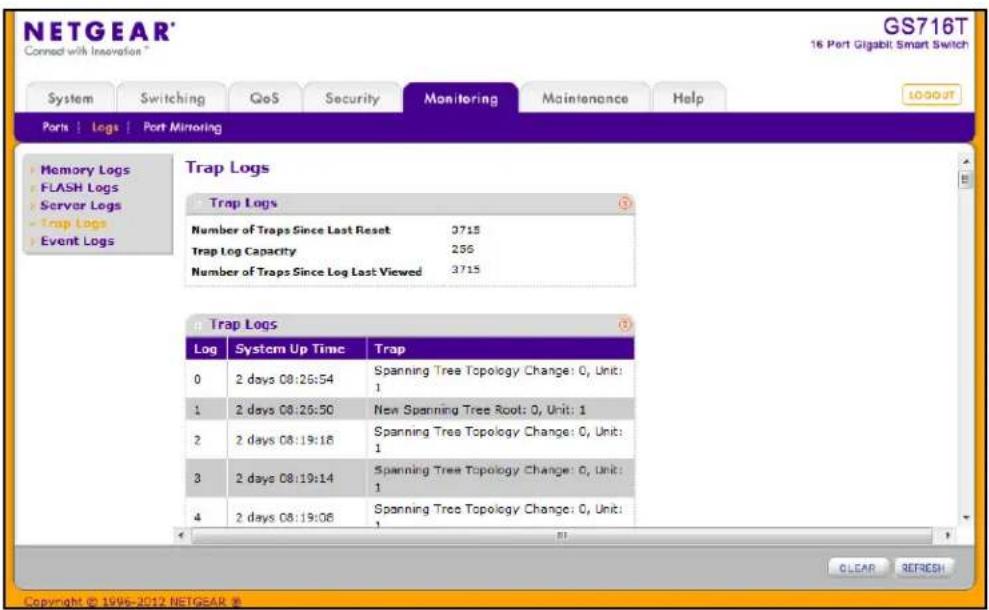
The following table describes the Trap Log information displayed on the screen.
| Field Description | |
| Number of Traps Since Last Reset | The number of traps that have occurred since the switch last reboot. |
| Trap Log Capacity | The maximum number of traps stored in the log. If the number of traps exceeds the capacity, the entries will overwrite the oldest entries. |
| Number of Traps Since Log Last Viewed | The number of traps that have occurred since the traps were last displayed. Displaying the traps by any method (such as terminal interface display, Web display, or upload file from switch) will cause this counter to be cleared to 0. |
The page also displays information about the traps that were sent.
| Field Description | |
| Log The sequence number of this trap. | |
| System Up Time The time at which this trap occurred, expressed in days, hours, minutes, and seconds since the last reboot of the switch. | |
| Trap Information identifying the trap. | |
Click Clear Counters to clear all the counters. This resets all statistics for the trap logs to the default values.
Event Logs
Use the Event Log page to display the event log, which is used to hold error messages for catastrophic events. After the event is logged and the updated log is saved in flash memory, the switch will be reset. The log can hold at least 2,000 entries and is erased when an attempt is made to add an entry after it is full. The event log is preserved across system resets.
To access the Event Log page, click the Monitoring > Logs tab, and then click the Event Logs link.
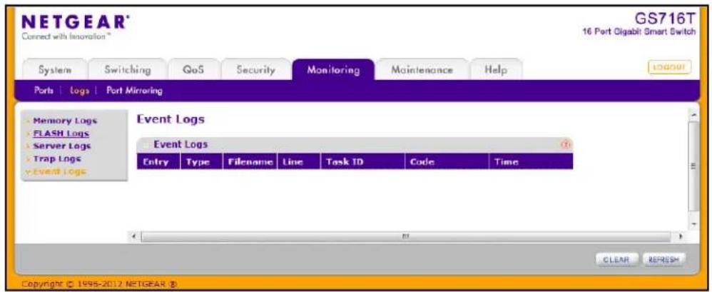
The following table describes the Event Log information displayed on the screen.
| Field Description | |
| Entry The number of the entry | within the event log. The most recent entry is first. |
| Type Specifies the type of entry. | |
| Filename The GS716T and GS724T | source code filename identifying the code that detected the event. |
| Line The line number within the source file of the code that detected the event. | |
| Task ID The OS-assigned ID of the task reporting the event. | |
| Code The event code passed to the event log handler by the code reporting the event. | |
| Time The time the event occurred, measured from the previous reset. | |
Use the buttons at the bottom of the page to perform the following actions:
- Click Clear to clear the messages out of the Event Log.
- Click Refresh to refresh the data on the screen and display the most current information.
Port Mirroring
The page under the Mirroring link allows you to view and configure port mirroring on the system.
Multiple Port Mirroring
Port mirroring selects the network traffic for analysis by a network analyzer. This is done for specific ports of the switch. As such, many switch ports are configured as source ports and one switch port is configured as a destination port. You have the ability to configure how traffic is mirrored on a source port. Packets that are received on the source port, that are transmitted on a port, or are both received and transmitted, can be mirrored to the destination port.
The packet that is copied to the destination port is in the same format as the original packet on the wire. This means that if the mirror is copying a received packet, the copied packet is VLAN tagged or untagged as it was received on the source port. If the mirror is copying a transmitted packet, the copied packet is VLAN tagged or untagged as it is being transmitted on the source port.
Use the Multiple Port Mirroring page to define port mirroring sessions.
To access the Multiple Port Mirroring page, click Monitoring > Port Mirroring. In the following figure, a port mirroring session is configured with ports g2, g3, and g6 as the source ports that are mirroring transmitted and received traffic to port g7.
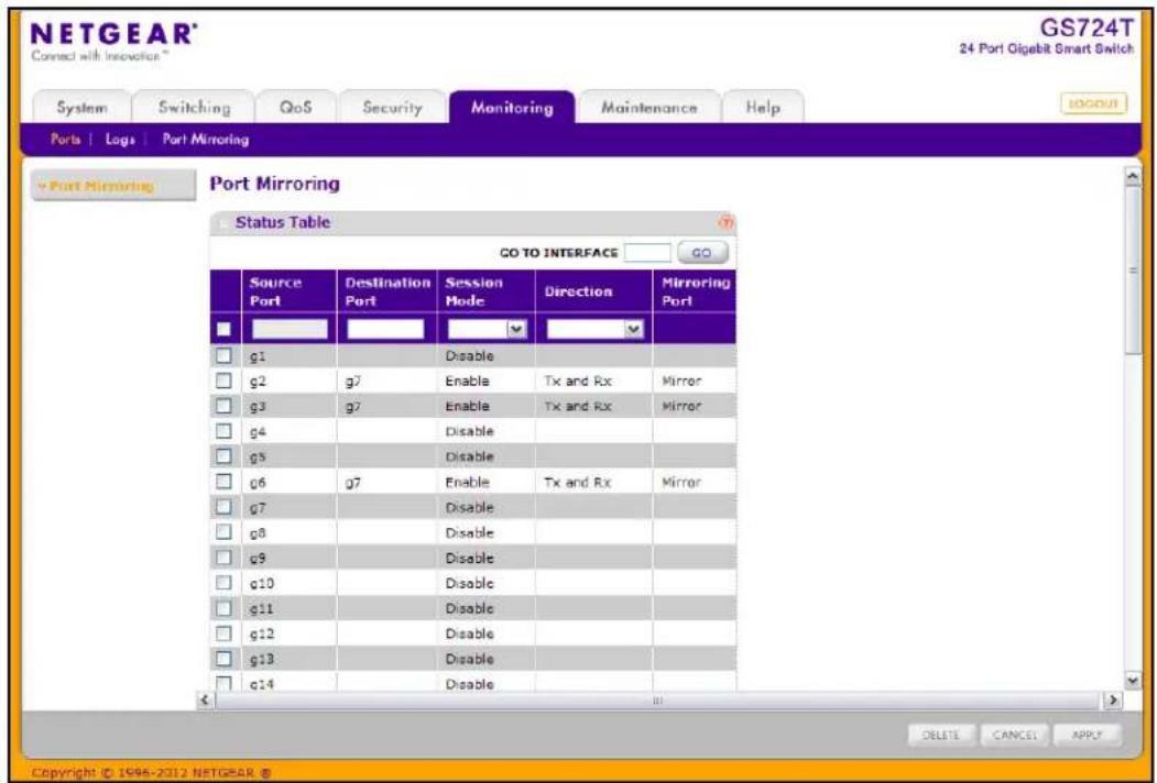
To configure Port Mirroring:
- Select the check box next to a port to configure it as a source port.
- In the Destination Port field, specify the port to which port traffic is be copied. Use the g1, g2,...format to specify the port. You can configure only one destination port on the system.
-
From the Session Mode menu, select the mode for port mirroring on the selected port:
-
Enable. Multiple Port Mirroring is active on the selected port.
-
Disable. Port mirroring is not active on the selected port, but the mirroring information is retained.
-
From the Direction menu, specify the direction of the Traffic to be mirrored from the configured mirrored port(s). The default value is Tx and Rx.
-
Tx and Rx. Enable both transmitting and receiving on the selected ports.
- Tx only. Enable only transmitting on the selected ports.
-
Rx only. Enable only receiving on the selected ports.
-
Click Apply to apply the settings to the system. If the port is configured as a source port, the Mirroring Port field value is Mirrored.
- To delete a mirrored port, select the check box next to the mirrored port, and then click Delete.
- Click Cancel to cancel the configuration on the screen and reset the data on the screen to the latest value of the switch.
GS716T and GS724T Gigabit Smart Switches
Use the features available from the Maintenance tab to help you manage the switch. The Maintenance tab contains links to the following features:
- Reset on page 253
- Upload File From Switch on page 255
- Download File To Switch on page 257
• File Management on page 261
• Troubleshooting on page 264
Reset
The Reset menu contains links to the following options:
• Device Reboot on page 253
• Factory Default on page 254
Device Reboot
Use the Device Reboot page to reboot the GS716T and GS724T.
To access the Device Reboot page, click Maintenance > Reset > Device Reboot.
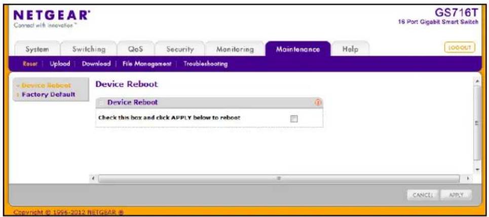
To reboot the switch:
- Select the check box on the page.
- Click Apply to reset the switch immediately, or click Cancel to abandon the reset request. After the switch reset begins, the management interface is not available until the switch completes the boot cycle. After the switch resets, the login screen appears.
Factory Default
Use the Factory Default page to reset the system configuration to the factory default values.
Note: If you reset the switch to the default configuration, the IP address is reset to 192.168.0.239, and the DHCP client is enabled. If you loose network connectivity after you reset the switch to the factory defaults, see Connecting the Switch to the Network on page 11.
To access the Factory Defaults page, click Maintenance > Reset > Factory Default.
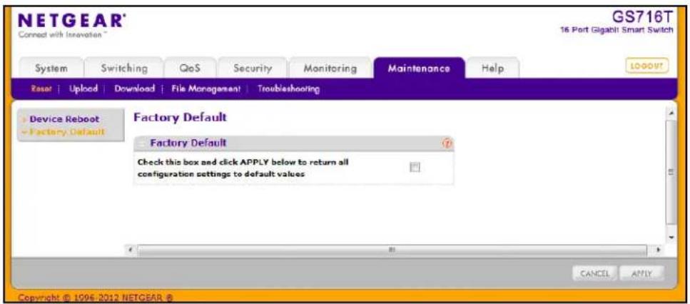
To reset the switch to the factory default settings:
- Select the check box on the page.
- Click Apply, or click Cancel to abandon the changes. The switch resets immediately.
Upload File From Switch
The switch supports system file uploads from the switch to a remote system by using either TFTP or HTTP.
The Upload menu contains links to the following options:
• TFTP File Upload on page 255
- HTTP File Download on page 260
TFTP File Upload
Use the TFTP File Upload page to upload configuration (ASCII), log (ASCII), and image (binary) files from the switch to an TFTP server on the network.
To display the File Upload page, click Maintenance >Upload >TFTP File Upload.
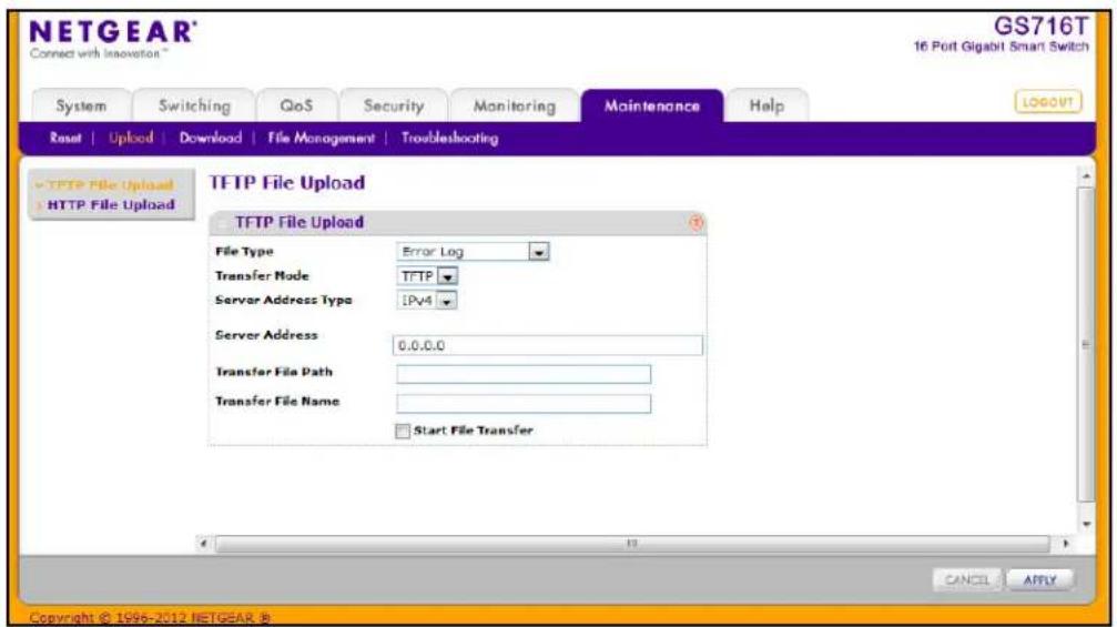
To upload a file from the switch to the TFTP server:
- Use the File Type menu to specify the type of file you want to upload:
• Code: Uploads a stored code image.
- Text Configuration: Uploads the text configuration file, which can be used as a backup copy or to download and apply to another switch.
- Error Log: Uploads the system error (persistent) log, sometimes referred to as the event log.
- Buffered Log: Uploads the system buffered (in-memory) log.
- Trap Log: Uploads the system trap records.
-
If the file type is Code, specify whether to upload image1 or image2. This field is only visible when Code is selected as the File Type.
-
From the Server Address Type filed, specify the format to use for the address you type in the TFTP Server Address field:
-
IPv4. Indicates the TFTP server address is an IP address in dotted-decimal format.
• DNS. Indicates the TFTP server address is a host name. -
In the Server Address field, specify the IP address or host name of the TFTP server. The address you type must be in the format indicated by the TFTP Server Address Type.
- In the Transfer File Path field, specify the path on the TFTP server where you want to put the file. You may enter up to 32 characters. Include the backslash at the end of the path. A path name with a space is not accepted. Leave this field blank to save the file to the root TFTP directory.
- In the Transfer File Name field, specify a destination file name for the file to upload. You may enter up to 32 characters. The transfer fails if you do not specify a file name. For a code transfer, use an .stk file extension.
- Select the Start File Transfer check box to initiate the file upload.
- Click Apply to begin the file transfer.
The last row of the table displays information about the progress of the file transfer. The page refreshes automatically until the file transfer completes or fails.
HTTP File Upload
Use the HTTP File Upload page to upload files of various types from the switch to the management system by using an HTTP session (for example, via your Web browser).
To display this page, click Maintenance > Upload > HTTP File Upload.
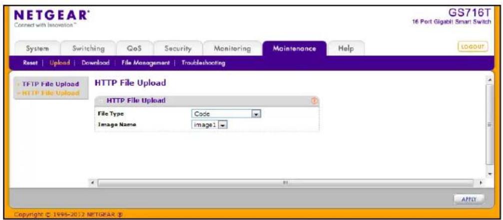
To upload a file from the switch to another system by using HTTP:
-
From the File Type menu, specify what type of file you want to upload from the switch:
-
Code: The code is the system software image, which is saved in one of two flash sectors called images (image1 and image2). The active image stores the active copy; while the other image stores a second copy. The device boots and runs from the active image. If the active image is corrupt, the system automatically boots from the non-active image. This is a safety feature for faults occurring during the boot upgrade process.
-
Text Configuration: A text-based configuration file enables you to edit a configured text file (startup-config) offline as needed without having to translate the contents for the switch to understand. The most common usage of text-based configuration is to upload a working configuration from a device, edit it offline to personalize it for another similar device (for example, change the device name, serial number, IP address), and download it to that device.
-
If you are uploading an GS716T and GS724T image (Code), select the image on the switch to upload to the management system. This field is visible only when Code is selected as the File Type.
- Click Apply. A window appears to allow you to open the text file on the management system or to save the image or text file to the management system.
- Click Cancel to cancel the operation on the screen and reset the data on the screen to the latest value of the switch.
Download File To Switch
The switch supports system file downloads from a remote system to the switch by using either TFTP or HTTP.
The Download menu contains links to the following options:
• TFTP File Download on page 257
- HTTP File Download on page 260
TFTP File Download
Use the Download File to Switch page to download device software, the image file, the configuration files and SSL files from a TFTP server to the switch.
You can also download files via HTTP. See HTTP File Download on page 260 for additional information.
To access the TFTP File Download page, click Maintenance > Download > TFTP File Download.
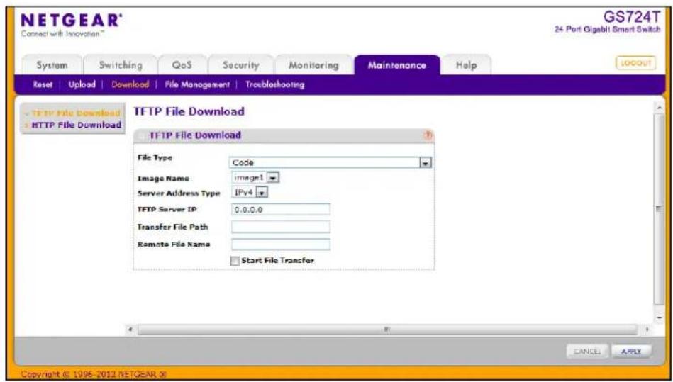
Before you download a file to the switch, the following conditions must be true:
- The file to download from the TFTP server is on the server in the appropriate directory.
• The file is in the correct format. - The switch has a path to the TFTP server.
To download a file to the switch from a TFTP server:
-
From the File Type menu, Specify what type of file you want to download to the switch:
-
Code: The code is the system software image, which is saved in one of two flash sectors called images (image1 and image2). The active image stores the active copy; while the other image stores a second copy. The device boots and runs from the active image. If the active image is corrupt, the system automatically boots from the non-active image. This is a safety feature for faults occurring during the boot upgrade process.
- Text Configuration: A text-based configuration file enables you to edit a configured text file (startup-config) offline as needed without having to translate the contents for the switch to understand. The most common usage of text-based configuration is to upload a working configuration from a device, edit it offline to personalize it for another similar device (for example, change the device name, serial number, IP address), and download it to that device.
• License Key: The license key file that activates certain features on the switch. - SSL Trusted Root Certificate PEM File: SSL Trusted Root Certificate File (PEM Encoded).
- SSL Server Certificate PEM File: SSL Server Certificate File (PEM Encoded).
- SSL DH Weak Encryption Parameter PEM File: SSL Diffie-Hellman Weak Encryption Parameter File (PEM Encoded).
-
SSL DH Strong Encryption Parameter PEM File: SSL Diffie-Hellman Strong Encryption Parameter File (PEM Encoded).
-
If you are downloading an GS716T and GS724T image (Code), select the image on the switch to overwrite. This field is visible only when Code is selected as the File Type.
Note: It is recommended that you not overwrite the active image. The system will display a warning that you are trying to overwrite the active image.
-
From the Server Address Type filed, specify the format for the address you type in the TFTP Server Address field
-
IPv4. Indicates the TFTP server address is an IP address in dotted-decimal format.
-
DNS. Indicates the TFTP server address is a host name.
-
In the Server Address field, specify the IP address or host name of the TFTP server. The address you type must be in the format indicated by the TFTP Server Address Type.
- In the Transfer File Path field, specify the path on the TFTP server where the file is located. You may enter up to 32 characters. Include the backslash at the end of the path. A path name with a space is not accepted. Leave this field blank to save the file to the root TFTP directory.
- In the Remote File Name field, specify the name of the file to download from the TFTP server. You may enter up to 32 characters. A file name with a space is not accepted.
- Select the Start File Transfer check box to initiate the file upload.
- Click Apply to begin the file transfer or Cancel to abandon the transfer.
The last row of the table displays information about the progress of the file transfer. The page refreshes automatically until the file transfer completes or fails.
To activate a software image that you download to the switch, see File Management on page 261.
HTTP File Download
Use the HTTP File Download page to download files of various types to the switch using an HTTP session (for example, via your Web browser).
To display this page, click Maintenance > Download > HTTP File Download.
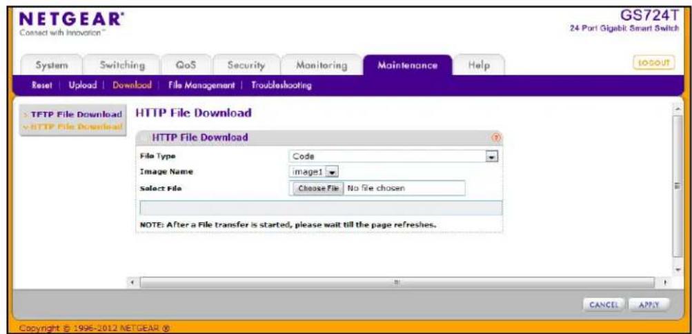
To download a file to the switch from by using HTTP:
-
From the File Type menu, Specify what type of file you want to download to the switch:
-
Code: The code is the system software image, which is saved in one of two flash sectors called images (image1 and image2). The active image stores the active copy; while the other image stores a second copy. The device boots and runs from the active image. If the active image is corrupt, the system automatically boots from the non-active image. This is a safety feature for faults occurring during the boot upgrade process.
- Text Configuration: A text-based configuration file enables you to edit a configured text file (startup-config) offline as needed without having to translate the contents for the switch to understand. The most common usage of text-based configuration is to upload a working configuration from a device, edit it offline to personalize it for another similar device (for example, change the device name, serial number, IP address), and download it to that device.
• License Key: The license key file that activates certain features on the switch. - SSL Trusted Root Certificate PEM File: SSL Trusted Root Certificate File (PEM Encoded).
- SSL Server Certificate PEM File: SSL Server Certificate File (PEM Encoded).
- SSL DH Weak Encryption Parameter PEM File: SSL Diffie-Hellman Weak Encryption Parameter File (PEM Encoded).
-
SSL DH Strong Encryption Parameter PEM File: SSL Diffie-Hellman Strong Encryption Parameter File (PEM Encoded).
-
If you are downloading an GS716T and GS724T image (Code), select the image on the switch to overwrite. This field is only visible when Code is selected as the File Type.
Note: It is recommended that you not overwrite the active image. The system will display a warning that you are trying to overwrite the active image.
- Click Browse to open a file upload window to locate the file you want to download.
- Click Cancel to cancel the operation on the screen and reset the data on the screen to the latest value of the switch.
- Click the Apply button to initiate the file download.
Note: After a file transfer is started, please wait until the page refreshes. When the page refreshes, the Select File option will be blanked out. This indicates that the file transfer is done.
File Management
The system maintains two versions of the GS716T and GS724T software in permanent storage. One image is the active image, and the second image is the backup image. The active image is loaded during subsequent switch restarts. This feature reduces switch down time when upgrading or downgrading the GS716T and GS724T software.
The File Management menu contains links to the following options:
• Dual Image Configuration on page 261
• Dual Image Status on page 263
Dual Image Configuration
The system running a legacy software version will ignore (not load) a configuration file created by the newer software version. When a configuration file created by the newer software version is discovered by the system running an older version of the software, the system will display an appropriate warning to the user.
Use the Dual Image Configuration page to set the boot image, configure an image description, or delete an image.
To display the Dual Image Configuration page, click Maintenance > File Management > Dual Image > Dual Image Configuration.
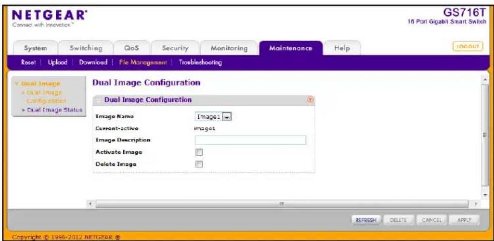
To configure Dual Image settings:
- Select the image to configure.
The Current-active field displays the name of the active image. - To configure a descriptive name for the selected software image, type the name in the Image Description field.
- To set the selected image as the active image, select the Active Image check box.
Note: After activating an image, you must perform a system reset of the switch in order to run the new code.
- To remove the selected image from permanent storage on the switch, select the Delete Image check box. You cannot delete the active image.
- Click Cancel to cancel the operation on the screen and reset the data on the screen to the latest value of the switch.
- Click Apply to apply the settings to the switch.
Dual Image Status
You can use the Dual Image Status page to view information about the system images on the device.
To display the Dual Image Status page, click Maintenance > File Management > Dual Image > Dual Image Status.
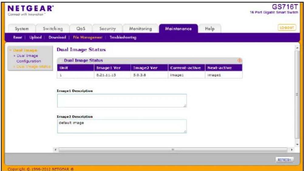
The following table describes the information on the Dual Image Status page.
| Field Description | |
| Unit The unit ID of the switch is always 1. | |
| Image1 Ver Displays the version of the image1 code file. | |
| Image2 Ver Displays the version of the image2 code file. | |
| Current-active Displays the currently active image on this switch. | |
| Next-active Displays the image to be used on the next restart of this switch. | |
| Image1 Description Displays the description associated with the image1 code file. | |
| Image2 Description Displays the description associated with the image2 code file. | |
Click Refresh to display the latest information from the switch.
For information about how to update or change the system images, see File Management on page 261.
Troubleshooting
The Troubleshooting menu contains links to the following options:
- Ping on page 264
• Ping IPv6 on page 266 - Traceroute on page 267
Ping
Use the Ping page to tell the switch to send a Ping request to a specified IP address. You can use this feature to check whether the switch can communicate with a particular network host.
To access the Ping page, click Maintenance > Troubleshooting > Ping.
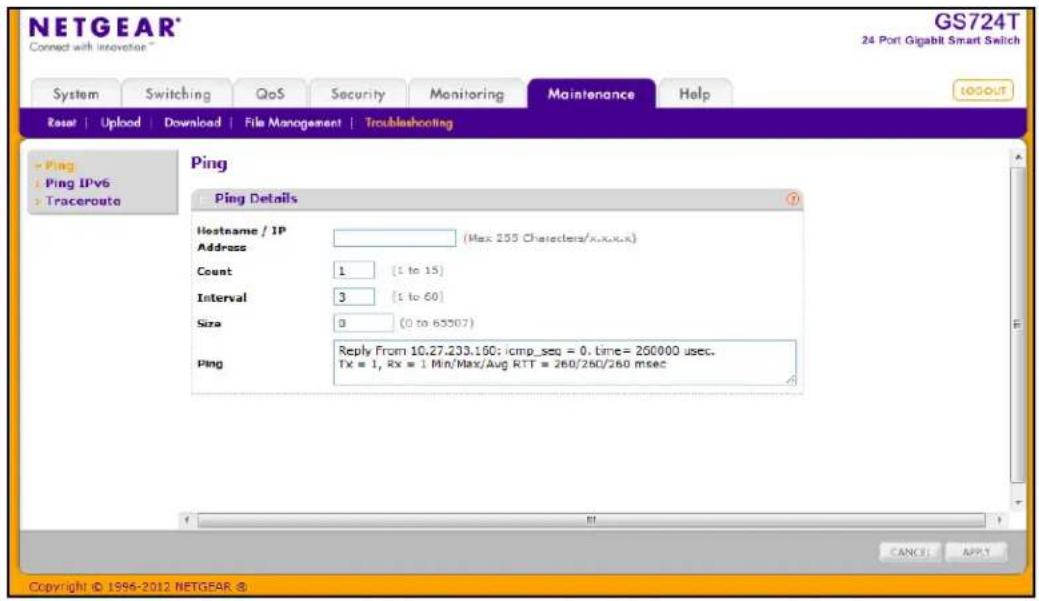
To configure the settings and ping a host on the network:
- In the Hostname/IP Address field, specify the IP address or the hostname of the station you want the switch to ping. The initial value is blank. This information is not retained across a power cycle.
-
Optionally, configure the following settings:
-
Count. Specify the number of pings to send. The valid range is 1–15.
- Interval. Specify the number of seconds between pings sent. The valid range is 1–60.
-
Size. Specify the size of the ping (ICMP) packet to send. The valid range is 0–65507.
-
Click Cancel to cancel the operation on the screen and reset the data on the screen to the latest value of the switch.
-
Click Apply to send the ping. The switch sends the number of pings specified in the Count field, and the results are displayed below the configurable data in the Ping area.
-
If successful, you will see "Reply From IP/Host: icmp_seq = 0. time = xx usec. Tx = x, Rx = x Min/Max/Avg RTT = x/x/x msec."
- If a reply to the ping is not received, you will see "Reply From IP/Host: Destination Unreachable. Tx = x, Rx = 0 Min/Max/Avg RTT = 0/0/0 msec".
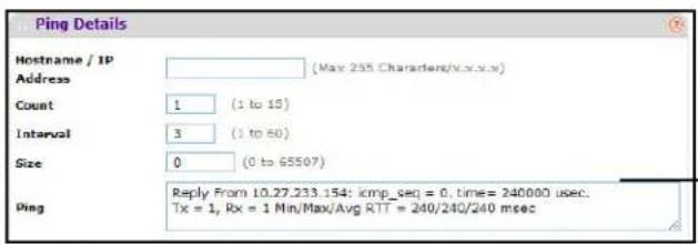
Ping Success Message
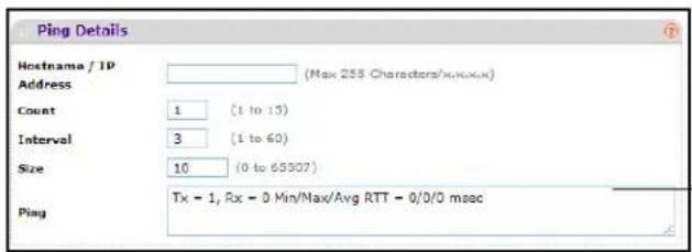
Ping Unsuccessful Message
Ping IPv6
Use the Ping IPv6 page to send a Ping request to a specified Hostname or IPv6 address. You can use this to check whether the switch can communicate with a particular IPv6 station. When you click the Apply button, the switch will send three pings and the results will be displayed below the configurable data.
To access the Ping IPv6 page, click Maintenance > Troubleshooting > Ping IPv6.
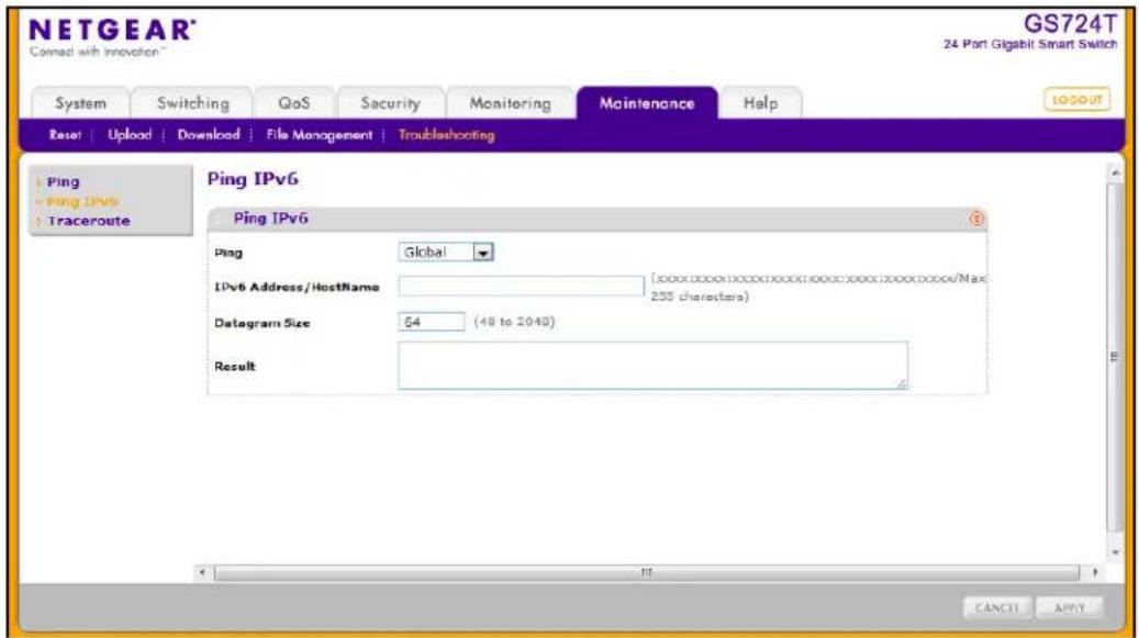
To configure the settings and ping a host on the network:
- In the Ping field, select either Global or Link Global to select either the global IPv6 Address/Hostname or Link Local Address to ping.
- In the Hostname/IP Address field, specify the IP address or the hostname of the station you want the switch to ping. The initial value is blank. This information is not retained across a power cycle.
-
Optionally, configure the following settings:
-
Link Local Address. Enter the link local address of the station you want the switch to ping. The initial value is blank. The Link Local Address you enter is not retained across a power cycle.
- IPv6 Address/Hostname. Enter the IPv6 address or Hostname of the station you want the switch to ping. The initial value is blank. The IPv6 Address or Hostname you enter is not retained across a power cycle.
-
Datagram Size. Enter the datagram size. The valid range is 48–2048.
-
Click Cancel to cancel the operation on the screen and reset the data on the screen to the latest value of the switch.
-
Click Apply to send the ping. The switch sends the number of pings specified in the Count field, and the results are displayed below the configurable data in the Result area.
- If successful, the output will be Send count=3, Receive count = n from (IPv6 Address).Average round trip time = n ms.
- If a reply to the ping is not received, the following displays: "Reply From IP/Host: Destination Unreachable. Tx = x, Rx = 0 Min/Max/Avg RTT = 0/0/0 msec".
Traceroute
Use the Traceroute utility to discover the paths that a packet takes to a remote destination.
To display this page, click Maintenance > Troubleshooting > Traceroute.
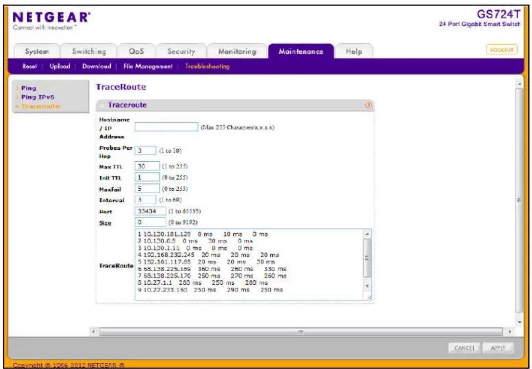
To configure the Traceroute settings and send probe packets to discover the route to a host on the network:
-
In the Hostname/IP Address field, specify the IP address or the hostname of the station you want the switch to ping. The initial value is blank. This information is not retained across a power cycle.
-
Optionally, configure the following settings:
- Probes Per Hop. Specify the number of times each hop should be probed. The valid range is 1–10.
- MaxTTL. Specify the maximum time-to-live for a packet in number of hops. The valid range is 1–255.
- InitTTL. Specify the initial time-to-live for a packet in number of hops. The valid range is 0–255.
- MaxFail. Specify the maximum number of failures allowed in the session. The valid range is 0–255.
- Interval. Specify the time between probes in seconds. The valid range is 1–60.
- Port. Specify the UDP destination port in probe packets. The valid range is 1–65535.
-
Size. Specify the size of probe packets. The valid range is 0–9192.
-
Click Cancel to cancel the operation on the screen and reset the data on the screen to the latest value of the switch.
-
Click Apply to initiate the traceroute. The results display in the TraceRoute area.
Use the features available from the Help tab to connect to online resources for assistance. The Help tab contains links to the following features:
• Online Help on page 269.
- Registration on page 271
Online Help
The Online Help includes the following pages:
• Support on page 269
• User Guide on page 270
Support
Use the Support page to connect to the Online Support site at netgear.com.
To access the Support page, click Help > Support.
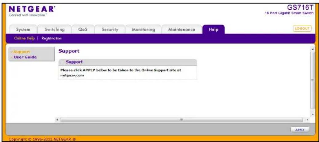
To connect to the NETGEAR support site for the GS716T and GS724T, click Apply.
User Guide
Use the User Guide page to access the GS716Tv2 and GS724Tv3 Software Administration Manual (the guide you are now reading) that is available on the NETGEAR Website.
To access the User Guide page, click Help > User Guide.
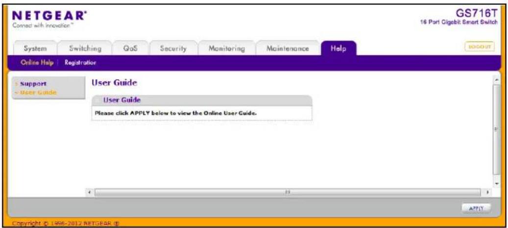
To access to the User Guide that is available online, click Apply.
Registration
Use the Registration page to register your GS716T or GS724T switch. Completing the registration confirms your email address, lowers technical support resolution time, and ensures your shipping address accuracy. NETGEAR, Inc. would also like to incorporate your feedback into future product development.
Note: NETGEAR will never sell or rent your email address, and you may opt out of communications at any time.
To access the Registration page, click Help > Registration.
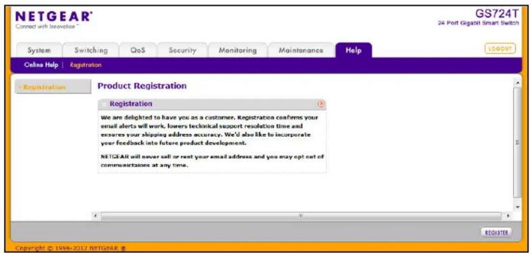
To register the switch, click Register. The switch attempts to contact the NETGEAR Registration Server.
For the product registration process to proceed, the administrative system running the browser must meet the following requirements:
• The administrative system must have Internet access.
• The browser must allow pop up windows.
- If the browser is Microsoft® Internet Explorer, ActiveX must be enabled.
If the switch successfully contacts the Registration Server, the NETGEAR Product Registration page opens in a new browser window. The product serial number and model number fields are pre populated. After you provide some basic information and click Register, the registration process is complete.
If you have not registered the product or have not disabled the registration reminders, the following pop-up window appears each time a user successfully logs on to the switch:
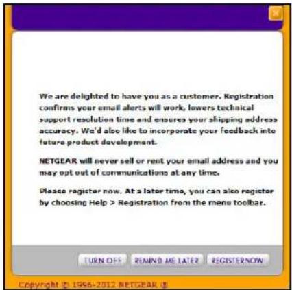
The registration pop-up window includes the following buttons:
- TURN OFF. Use this button to turn off the Product Registration feature and to prevent the registration reminder pop-up window from appearing on subsequent successful login sessions.
- REMIND ME LATER. The pop-up window is closed without taking any action, and the registration reminder pop-up appears on next successful login.
- REGISTER NOW. The NETGEAR Registration Server is contacted to initiate the registration process.
Hardware Specifications and Default Values

GS716T and GS724T Gigabit Smart Switches Specifications
The GS716T and GS724T Gigabit Smart Switches conform to the TCP/IP, UDP, HTTP, ICMP, TFTP, DHCP, IEEE 802.1D, IEEE 802.1p, and IEEE 802.1Q standards.
GS716T Specifications
| Feature Value | |
| Interfaces 16 10/100/1000 Ethernet | ports |
| Flash memory size 16 MB | |
| SRAM size and type 64 MB DDR |
GS724T Specifications
| Feature Value | |
| Interfaces 24 10/100/1000 Ethernet | portsTwo 1000M SFP Gigabit Ethernet ports |
| Flash memory size 16 MB | |
| SRAM size and type 64 MB DDR |
GS716T and GS724T Switch Performance
| Feature Value | |
| Switching capacity Non-Blocking Full WireSpeed on all packet sizes | |
| Forwarding method Store and Forward | |
| Packet forwarding rate 10M:14,880 | pps/100M:148,810 pps/1G:1,488,000 pps |
| MAC addresses 4K | |
| Green Ethernet Power consumption | savings by cable length (<10m)Automatic power down on port when link is down |
GS716T and GS724T Switch Features and Defaults
Port Characteristics
| Feature Sets Supported Default | ||
| Auto negotiation/static speed/duplex | All ports Auto negotiation | |
| Auto MDI/MDIX N/A Enabled | ||
| 802.3x flow control/back pressure 1 | (per system) Disabled | |
| Port mirroring 1 Disabled | ||
| Port trunking (aggregation) 4 Pre-configured | ||
| 802.1D spanning tree | 1 Disabled | |
| 802.1w RSTP | 1 Disabled | |
| 802.1s spanning tree | 3 instances | Disabled |
| Static 802.1Q tagging | 64 | VID = 1 |
| Learning process | Supports Static and dynamic MAC entries | Dynamic learning is enabled by default |
Traffic Control
| Feature Sets Supported Default | ||
| Storm control All ports Disabled | ||
| Jumbo frame All ports Disabled | Max = 9216 bytes |
Quality Of Service
| Feature Sets Supported Default | ||
| Number of queues 4 N/A | ||
| Port based N/A N/A | ||
| 802.1p 1 Enabled | ||
| DSCP 1 Disabled | ||
| Rate limiting All ports Disabled | ||
| Auto-QoS All ports Disabled |
Security
| Feature Sets Supported Default | ||
| 802.1X All ports Disabled | ||
| MAC ACL 100 (Shared with IPv4/IP) | v6 ACLs) All MAC packets allowed | |
| IPv4 access list 100 (shared with M | AC ACL, IPv6ACL) | All IP packets allowed |
| IPv6 access list 100 (shared with M | AC ACL, IPv6ACLs) | All IPv6 packets allowed |
| Password control access | 1 Idle timeout = 5 mins. | Password = “password” |
| Management security | 1 profile with 20 rules forHTTP/HTTPS/SNMP access toallow/deny an IP address/subnet | All IP addresses allowed |
| Port MAC lock down | All ports Disabled |
System Setup
| Feature Sets Supported Default | ||
| Boot code update 1 N/A | ||
| DHCP/manual IP 1 DHCP enabled/ | 192.168.0.239 | |
| Default gateway 1 192.168.0.254 | ||
| System name configuration 1 NULL | ||
| Configuration save/restore 1 N/A | ||
| Firmware upgrade 1 N/A | ||
| Restore defaults 1 (Web and front-panel button) N/A | ||
| Dual image support 1 Enabled | ||
| Factory reset 1 N/A |
Management
| Feature Sets Supported Default | ||
| Multi-session Web connections 16 | Enabled | |
| SNMPv1/V2cSNMP v3 | Max 5 community entries Enabled (read, read-write communities) | |
| Time control | 1 (Local or SNTP) | Local Time enabled |
| LLDP/LLDP-MED All ports Disabled | ||
| Logging | 3 (Memory/Flash/Server) | Memory Log enabled |
| MIB support | 1 Disabled | |
| Smart Control Center | N/A | Enabled |
| Statistics | N/A | N/A |
| IPv6 management (IPv6 networking, DHCPv6, IPv6 DNS host, IPv6 ping, etc.) | N/A | N/A |
Other Features
| Feature Sets Supported Default | ||
| IGMP snooping v1/v2 All ports Disabled | ||
| Configurations upload/download 1 N/A | ||
| EAPoL flooding All ports Disabled | ||
| BPDU flooding All ports Disabled | ||
| Static multicast groups 8 Disabled | ||
| Filter multicast control 1 Disabled |
This chapter contains information about how to configure the following features:
• Virtual Local Area Networks (VLANs) on page 279
- Access Control Lists (ACLs) on page 282
• Differentiated Services (DiffServ) on page 285
- 802.1X on page 290
- MSTP on page 293
Virtual Local Area Networks (VLANs)
A local area network (LAN) can generally be defined as a broadcast domain. Hubs, bridges, or switches in the same physical segment or segments connect all end node devices. End nodes can communicate with each other without the need for a router. Routers connect LANs together, routing the traffic to the appropriate port.
A virtual LAN (VLAN) is a local area network with a definition that maps workstations on some basis other than geographic location (for example, by department, type of user, or primary application). To enable traffic to flow between VLANs, traffic must go through a router, just as if the VLANs were on two separate LANs.
A VLAN is a group of PCs, servers, and other network resources that behave as if they were connected to a single network segment—even though they might not be. For example, all marketing personnel might be spread throughout a building. Yet if they are all assigned to a single VLAN, they can share resources and bandwidth as if they were connected to the same segment. The resources of other departments can be invisible to the marketing VLAN members, accessible to all, or accessible only to specified individuals, depending on how the IT manager has set up the VLANs.
VLANs have a number of advantages:
- It is easy to do network segmentation. Users that communicate most frequently with each other can be grouped into common VLANs, regardless of physical location. Each group's traffic is contained largely within the VLAN, reducing extraneous traffic and improving the efficiency of the whole network.
- They are easy to manage. The addition of nodes, as well as moves and other changes, can be dealt with quickly and conveniently from a management interface rather than from the wiring closet.
- They provide increased performance. VLANs free up bandwidth by limiting node-to-node and broadcast traffic throughout the network.
- They ensure enhanced network security. VLANs create virtual boundaries that can be crossed only through a router. So standard, router-based security measures can be used to restrict access to each VLAN.
Packets received by the switch are treated in the following way:
- When an untagged packet enters a port, it is automatically tagged with the port's default VLAN ID tag number. Each port has a default VLAN ID setting that is user configurable (the default setting is 1). The default VLAN ID setting for each port can be changed in the Port PVID Configuration screen. See Port VLAN ID Configuration on page 92.
- When a tagged packet enters a port, the tag for that packet is unaffected by the default VLAN ID setting. The packet proceeds to the VLAN specified by its VLAN ID tag number.
- If the port through which the packet entered does not have membership with the VLAN specified by the VLAN ID tag, the packet is dropped.
- If the port is a member of the VLAN specified by the packet's VLAN ID, the packet can be sent to other ports with the same VLAN ID.
- Packets leaving the switch are either tagged or untagged, depending on the setting for that port's VLAN membership properties. A U for a given port means that packets leaving the switch from that port are untagged. Inversely, a T for a given port means that packets leaving the switch from that port are tagged with the VLAN ID that is associated with the port.
The example given in this section comprises numerous steps to illustrate a wide range of configurations to help provide an understanding of tagged VLANs.
VLAN Example Configuration
This example demonstrates several scenarios of VLAN use and describes how the switch handles tagged and untagged traffic.
In this example, you create two new VLANs, change the port membership for default VLAN and assign port members to the two new VLANs:
- In the Basic VLAN Configuration screen (see VLAN Configuration on page 89), create the following VLANs:
• A VLAN with VLAN ID 10.
• A VLAN with VLAN ID 20.
-
In the VLAN Membership screen (see VLAN Membership Configuration on page 90) specify the VLAN membership as follows:
-
For the default VLAN with VLAN ID 1, specify the following members: port 7 (U) and port 8 (U).
- For the VLAN with VLAN ID 10, specify the following members: port 1 (U), port 2 (U), and port 3 (T).
-
For the VLAN with VLAN ID 20, specify the following members: port 4 (U), port 5 (T), and port 6 (U).
-
In the Port PVID Configuration screen (see Port VLAN ID Configuration on page 92), specify the PVID for ports g1 and g4 so that packets entering these ports are tagged with the port VLAN ID:
-
Port g1: PVID 10
-
Port g4: PVID 20
-
With the VLAN configuration that you set up, the following situations produce results as described:
- If an untagged packet enters port 1, the switch tags it with VLAN ID 10. The packet has access to port 2 and port 3. The outgoing packet is stripped of its tag to leave port 2 as an untagged packet. For port 3, the outgoing packet leaves as a tagged packet with VLAN ID 10.
- If a tagged packet with VLAN ID 10 enters port 3, the packet has access to port 1 and port 2. If the packet leaves port 1 or port 2, it is stripped of its tag to leave the switch as an untagged packet.
- If an untagged packet enters port 4, the switch tags it with VLAN ID 20. The packet has access to port 5 and port 6. The outgoing packet is stripped of its tag to become an untagged packet as it leaves port 6. For port 5, the outgoing packet leaves as a tagged packet with VLAN ID 20.
Access Control Lists (ACLs)
ACLs ensure that only authorized users have access to specific resources while blocking off any unwarranted attempts to reach network resources.
ACLs are used to provide traffic flow control, restrict contents of routing updates, decide which types of traffic are forwarded or blocked, and provide security for the network. ACLs are normally used in firewall routers that are positioned between the internal network and an external network, such as the Internet. They can also be used on a router positioned between two parts of the network to control the traffic entering or exiting a specific part of the internal network. The added packet processing required by the ACL feature does not affect switch performance. That is, ACL processing occurs at wire speed.
Access lists are a sequential collection of permit and deny conditions. This collection of conditions, known as the filtering criteria, is applied to each packet that is processed by the switch or the router. The forwarding or dropping of a packet is based on whether or not the packet matches the specified criteria.
Traffic filtering requires the following two basic steps:
- Create an access list definition.
The access list definition includes rules that specify whether traffic matching the criteria is forwarded normally or discarded. Additionally, you can assign traffic that matches the criteria to a particular queue or redirect the traffic to a particular port. A default deny all rule is the last rule of every list.
- Apply the access list to an interface in the inbound direction.
The GS716T and GS724T Smart Switches allows ACLs to be bound to physical ports and LAGs. The switch software supports MAC ACLs and IP ACLs.
MAC ACL Example Configuration
The following example shows how to create a MAC-based ACL that permits Ethernet traffic from the Sales department on specified ports and denies all other traffic on those ports.
- From the MAC ACL screen, create an ACL with the name Sales_ACL for the Sales department of your network (See MAC ACL on page 211).
By default, this ACL will be bound on the inbound direction, which means the switch will examine traffic as it enters the port.
- From the MAC Rules screen, create a rule for the Sales_ACL with the following settings:
• ID: 1
• Action: Permit
- Assign Queue: 0
- Match Every: False
- CoS: 0
- Destination MAC: 01:02:1A:BC:DE:EF
GS716T and GS724T Gigabit Smart Switches
- Destination MAC Mask: 00:00:00:00:FF:FF
- Source MAC: 02:02:1A:BC:DE:EF
• Source MAC Mask: 00:00:00:00:FF:FF - VLAN ID: 200

For detailed information about MAC ACL rules, see MAC Rules on page 212.
- From the MAC Binding Configuration screen, assign the Sales_ACL to Ethernet ports 6, 7, and 8, and then click Apply (See MAC Binding Configuration on page 214).
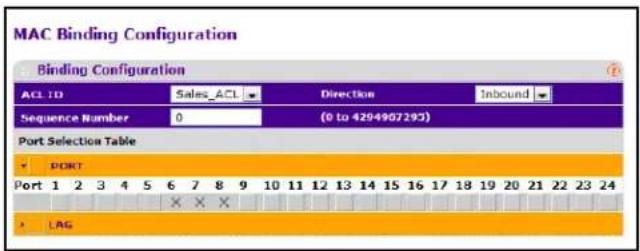
You can assign an optional sequence number to indicate the order of this access list relative to other access lists if any are already assigned to this interface and direction.
- Click Apply (See MAC Binding Configuration on page 214).
The MAC Binding Table displays the interface and MAC ACL binding information (See MAC Binding Table on page 215).
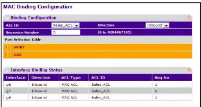
The ACL named Sales_ACL looks for Ethernet frames with destination and source MAC addresses and MAC masks defined in the rule. Also, the frame must be tagged with VLAN ID 2, which is the Sales department VLAN. The CoS value of the frame must be 0, which is the default value for Ethernet frames. Frames that match this criteria are permitted on interfaces 6, 7, and 8 and are assigned to the hardware egress queue 0, which is the default queue. All other traffic is explicitly denied on these interfaces. To allow additional traffic to enter these ports, you must add a new permit rule with the desired match criteria and bind the rule to interfaces 6, 7, and 8.
Standard IP ACL Example Configuration
The following example shows how to create an IP-based ACL that prevents any IP traffic from the Finance department from being allowed on the ports that are associated with other departments. Traffic from the Finance department is identified by each packet's network IP address.
- From the IP ACL screen, create a new IP ACL with an IP ACL ID of 1 (See IP ACL on page 216).
-
From the IP Rules screen, create a rule for IP ACL 1 with the following settings:
-
Rule ID: 1
• Action: Deny - Assign Queue ID: 0 (optional: 0 is the default value)
- Match Every: False
- Source IP Address: 192.168.187.0
• Source IP Mask: 255.255.255.0
For additional information about IP ACL rules, see IP Rules on page 217.
-
Click Add.
-
From the IP Rules screen, create a second rule for IP ACL 1 with the following settings:
-
Rule ID: 2
- Action: Permit
-
Match Every: True
-
Click Add.
-
From the IP Binding Configuration page, assign ACL ID 1 to the Ethernet ports 2, 3, and 4, and assign a sequence number of 1 (See IP Binding Configuration on page 226).
By default, this IP ACL is bound on the inbound direction, so it examines traffic as it enters the switch.
- Click Apply.
- Use the IP Binding Table screen to view the interfaces and IP ACL binding information (See IP Binding Table on page 227).
The IP ACL in this example matches all packets with the source IP address and subnet mask of the Finance department's network and deny it on the Ethernet interfaces 2, 3, and 4 of the switch. The second rule permits all non-Finance traffic on the ports. The second rule is required because there is an explicit deny all rule as the lowest priority rule.
Differentiated Services (DiffServ)
Standard IP-based networks are designed to provide best effort data delivery service. Best effort service implies that the network deliver the data in a timely fashion, although there is no guarantee that it will. During times of congestion, packets may be delayed, sent sporadically, or dropped. For typical Internet applications, such as e-mail and file transfer, a slight degradation in service is acceptable and in many cases unnoticeable. However, any degradation of service has undesirable effects on applications with strict timing requirements, such as voice or multimedia.
Quality of Service (QoS) can provide consistent, predictable data delivery by distinguishing between packets that have strict timing requirements from those that are more tolerant of delay. Packets with strict timing requirements are given special treatment in a QoS-capable network. With this in mind, all elements of the network must be QoS-capable. If one node is unable to meet the necessary timing requirements, this creates a deficiency in the network path and the performance of the entire packet flow is compromised.
There are two basic types of QoS:
- Integrated Services: network resources are apportioned based on request and are reserved (resource reservation) according to network management policy (RSVP, for example).
- Differentiated Services: network resources are apportioned based on traffic classification and priority, giving preferential treatment to data with strict timing requirements.
The GS716T and GS724T Smart Switches supports DiffServ.
The DiffServ feature contains a number of conceptual QoS building blocks you can use to construct a differentiated service network. Use these same blocks in different ways to build other types of QoS architectures.
There are 3 key QoS building blocks needed to configure DiffServ:
• Class
• Policy
• Service (i.e., the assignment of a policy to a directional interface)
Class
You can classify incoming packets at layers 2, 3, and 4 by inspecting the following information for a packet:
- Source/destination MAC address
- EtherType
• Class of Service (802.1p priority) value (first/only VLAN tag)
• VLAN ID range (first/only VLAN tag) - IP Service Type octet (also known as: ToS bits, Precedence value, DSCP value)
- Layer 4 protocol (TCP, UDP etc.)
- Layer 4 source/destination ports
- Source/destination IP address
From a DiffServ point of view, there are two types of classes:
- DiffServ traffic classes
- DiffServ service levels/forwarding classes
DiffServ Traffic Classes
With DiffServ, you define which traffic classes to track on an ingress interface. You can define simple BA classifiers (DSCP) and a wide variety of multifield (MF) classifiers:
• Layer 2; Layers 3, 4 (IP only)
- Protocol-based
- Address-based
You can combine these classifiers with logical AND or OR operations to build complex MF-classifiers (by specifying a class type of all or any, respectively). That is, within a single class, multiple match criteria are grouped together as an AND expression or a sequential OR expression, depending on the defined class type. Only classes of the same type can be nested; class nesting does not allow for the negation (i.e., exclude option) of the referenced class.
To configure DiffServ, you must define service levels, namely the forwarding classes/PHBs identified by a given DSCP value, on the egress interface. These service levels are defined by configuring BA classes for each.
Creating Policies
Use DiffServ policies to associate a collection of classes that you configure with one or more QoS policy statements. The result of this association is referred to as a policy.
From a DiffServ perspective, there are two types of policies:
• Traffic Conditioning Policy: a policy applied to a DiffServ traffic class
• Service Provisioning Policy: a policy applied to a DiffServ service level
You must manually configure the various statements and rules used in the traffic conditioning and service provisioning policies to achieve the desired Traffic Conditioning Specification (TCS) and the Service Level Specification (SLS) operation, respectively.
Traffic Conditioning Policy
Traffic conditioning pertains to actions performed on incoming traffic. There are several distinct QoS actions associated with traffic conditioning:
- Dropping: drop a packet upon arrival. This is useful for emulating access control list operation using DiffServ, especially when DiffServ and ACL cannot co-exist on the same interface.
- Marking IP DSCP or IP Precedence: marking/re-marking the DiffServ code point in a packet with the DSCP value representing the service level associated with a particular DiffServ traffic class. Alternatively, the IP Precedence value of the packet can be marked/re-marked.
- Marking CoS (802.1p): sets the three-bit priority field in the first/only 802.1p header to a specified value when packets are transmitted for the traffic class. An 802.1p header is inserted if it does not already exist. This is useful for assigning a layer 2 priority level based on a DiffServ forwarding class (i.e., DSCP or IP Precedence value) definition to convey some QoS characteristics to downstream switches which do not routinely look at the DSCP value in the IP header.
-
Policing: a method of constraining incoming traffic associated with a particular class so that it conforms to the terms of the TCS. Special treatment can be applied to out-of-profile packets that are either in excess of the conformance specification or are non-conformant. The DiffServ feature supports the following types of traffic policing treatments (actions):
-
drop: the packet is dropped
- mark cos: the 802.1p user priority bits are (re)marked and forwarded
- mark dscp: the packet DSCP is (re)marked and forwarded
- mark prec: the packet IP Precedence is (re)marked and forwarded
- send: the packet is forwarded without DiffServ modification
Color Mode Awareness: Policing in the DiffServ feature uses either color blind or color aware mode. Color blind mode ignores the coloration (marking) of the incoming packet. Color aware mode takes into consideration the current packet marking when determining the policing outcome. An auxiliary traffic class is used in conjunction with the policing definition to specify a value for one of the 802.1p, IP DSCP, or IP Precedence fields designating the incoming color value to be used as the conforming color. The color of exceeding traffic may be optionally specified as well.
- Counting: updating octet and packet statistics to keep track of data handling along traffic paths within DiffServ. In this DiffServ feature, counters are not explicitly configured by the user, but are designed into the system based on the DiffServ policy being created. See the Statistics section of this document for more details.
- Assigning QoS Queue: directs traffic stream to the specified QoS queue. This allows a traffic classifier to specify which one of the supported hardware queues are used for handling packets belonging to the class.
- Redirecting: forces classified traffic stream to a specified egress port (physical or LAG). This can occur in addition to any marking or policing action. It may also be specified along with a QoS queue assignment.
DiffServ Example Configuration
To create a DiffServ Class/Policy and attach it to a switch interface, follow these steps:
-
From the QoS Class Configuration screen, create a new class with the following settings:
-
Class Name: Class1
- Class Type: All
For more information about this screen, see Class Configuration on page 161.
- Click the Class1 hyperlink to view the DiffServ Class Configuration screen for this class.
-
Configure the following settings for Class1:
-
Protocol Type: UDP
• Source IP Address: 192.12.1.0
• Source Mask: 255.255.255.0 - Source L4 Port: Other, and enter 4567 as the source port value
- Destination IP Address: 192.12.2.0
- Destination Mask: 255.255.255.0
- Destination L4 Port: Other, and enter 4568 as the destination port value
For more information about this screen, see Class Configuration on page 161.
-
Click Apply.
-
From the Policy Configuration screen, create a new policy with the following settings:
• Policy Selector: Policy1
- Member Class: Class1
For more information about this screen, see Policy Configuration on page 167.
- Click Add to add the new policy.
- Click the Policy1 hyperlink to view the Policy Class Configuration screen for this policy.
-
Configure the Policy attributes as follows:
-
Assign Queue: 3
• Policy Attribute: Simple Policy
• Color Mode: Color Blind
• Committed Rate: 1000000 Kbps
• Committed Burst Size: 128 KB - Confirm Action: Send
- Violate Action: Drop
For additional information about this screen, see Policy Configuration on page 167.
- From the Service Configuration screen, select the check box next to interfaces g7 and g8 to attach the policy to these interfaces, and then click Apply (See Service Configuration on page 170).
All UDP packet flows destined to the 192.12.2.0 network with an IP source address from the 192.12.1.0 network that have a Layer 4 Source port of 4567 and Destination port of 4568 from this switch on ports 7 and 8 are assigned to hardware queue 3.
On this network, traffic from streaming applications uses UDP port 4567 as the source and 4568 as the destination. This real-time traffic is time sensitive, so it is assigned to a high-priority hardware queue. By default, data traffic uses hardware queue 0, which is designated as a best-effort queue.
Also the confirmed action on this flow is to send the packets with a committed rate of 100.0000 and burst size of 128 KB. Packets that violate the committed rate and burst size are dropped.
802.1X
Local Area Networks (LANs) are often deployed in environments that permit unauthorized devices to be physically attached to the LAN infrastructure, or permit unauthorized users to attempt to access the LAN through equipment already attached. In such environments, it may be desirable to restrict access to the services offered by the LAN to those users and devices that are permitted to use those services.
Port-based network access control makes use of the physical characteristics of LAN infrastructures in order to provide a means of authenticating and authorizing devices attached to a LAN port that has point-to-point connection characteristics and of preventing access to that port in cases in which the authentication and authorization process fails. In this context, a port is a single point of attachment to the LAN, such as ports of MAC bridges and associations between stations or access points in IEEE 802.11 Wireless LANs.
The IEEE 802.11 standard describes an architectural framework within which authentication and consequent actions take place. It also establishes the requirements for a protocol between the authenticator (the system that passes an authentication request to the authentication server) and the supplicant (the system that requests authentication), as well as between the authenticator and the authentication server.
The GS716T and GS724T Smart Switches supports a guest VLAN, which allows unauthenticated users to have limited access to the network resources.
Note: You can use QoS features to provide rate limiting on the guest VLAN to limit the network resources the guest VLAN provides.
Another 802.1X feature is the ability to configure a port to Enable/Disable EAPoL packet forwarding support. You can disable or enable the forwarding of EAPoL when 802.1X is disabled on the device.
The ports of an 802.1X authenticator switch provide the means in which it can offer services to other systems reachable via the LAN. Port-based network access control allows the operation of a switch's ports to be controlled in order to ensure that access to its services is only permitted by systems that are authorized to do so.
Port access control provides a means of preventing unauthorized access by supplicants to the services offered by a system. Control over the access to a switch and the LAN to which it is connected can be desirable in order to restrict access to publicly accessible bridge ports or to restrict access to departmental LANs.
Access control is achieved by enforcing authentication of supplicants that are attached to an authenticator's controlled ports. The result of the authentication process determines whether the supplicant is authorized to access services on that controlled port.
A Port Access Entity (PAE) is able to adopt one of two distinct roles within an access control interaction:
- Authenticator: A Port that enforces authentication before allowing access to services available via that Port.
- Supplicant: A Port that attempts to access services offered by the Authenticator.
Additionally, there exists a third role:
- Authentication server: Performs the authentication function necessary to check the credentials of the Supplicant on behalf of the Authenticator.
All three roles are required in order to complete an authentication exchange.
The GS716T and GS724T Smart Switches supports the Authenticator role only, in which the PAE is responsible for communicating with the Supplicant. The Authenticator PAE is also responsible for submitting the information received from the Supplicant to the Authentication Server in order for the credentials to be checked, which will determine the authorization state of the Port. The Authenticator PAE controls the authorized/ unauthorized state of the controlled Port depending on the outcome of the RADIUS-based authentication process.
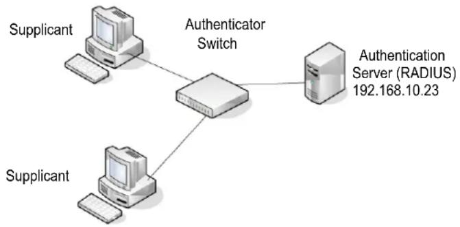
flowchart
graph TD
    A["Supplicant"] --> B["Authenticator Switch"]
    C["Supplicant"] --> B
    B --> D["Authentication Server (RADIUS) 192.168.10.23"]
802.1X Example Configuration
This example shows how to configure the switch so that 802.1X-based authentication is required on the ports in a corporate conference room (g1–g8). These ports are available to visitors and need to be authenticated before granting access to the network. The authentication is handled by an external RADIUS server. When the visitor is successfully authenticated, traffic is automatically assigned to the guest VLAN. This example assumes that a VLAN has been configured with a VLAN ID of 150 and VLAN Name of Guest.
- From the Port Authentication screen, select ports g1 through g8.
- From the Port Control menu, select Unauthorized.
The Port Control setting for all other ports where authentication is not needed should Authorized. When the Port Control setting is Authorized, the port is unconditionally put in a force-Authorized state and does not require any authentication. When the Port Control setting is Auto, the authenticator PAE sets the controlled port mode.
-
In the Guest VLAN field for ports g1–g8, enter 150 to assign these ports to the guest VLAN.
You can configure additional settings to control access to the network through the ports. See Port Security Interface Configuration on page 205 for information about the settings. -
Click Apply.
-
From the 802.1X Configuration screen, set the Port Based Authentication State and Guest VLAN Mode to Enable, and then click Apply (See Port Security Configuration on page 204).
This example uses the default values for the port authentication settings, but there are several additional settings that you can configure. For example, the EAPOL Flood Mode field allows you to enable the forwarding of EAPoL frames when 802.1X is disabled on the device.
- From the RADIUS Server Configuration screen, configure a RADIUS server with the following settings:
• Server Address: 192.168.10.23
- Secret Configured: Yes
- Secret: secret123
• Active: Primary
For more information, see RADIUS Configuration on page 175.
-
Click Add.
-
From the Authentication List screen, configure the default List to use RADIUS as the first authentication method (See Authentication List Configuration on page 184).
This example enables 802.1X-based port security on the GS716T and GS724T switch and prompts the hosts connected on ports g1–g8 for an 802.1X-based authentication. The switch passes the authentication information to the configured RADIUS server.
MSTP
Spanning Tree Protocol (STP) runs on bridged networks to help eliminate loops. If a bridge loop occurs, the network can become flooded with traffic. IEEE 802.1s Multiple Spanning Tree Protocol (MSTP) supports multiple instances of Spanning Tree to efficiently channel VLAN traffic over different interfaces. Each instance of the Spanning Tree behaves in the manner specified in IEEE 802.1w, Rapid Spanning Tree, with slight modifications in the working but not the end effect (chief among the effects is the rapid transitioning of the port to the Forwarding state).
The difference between the RSTP and the traditional STP (IEEE 802.1D) is the ability to configure and recognize full duplex connectivity and ports that are connected to end stations, resulting in rapid transitioning of the port to the Forwarding state and the suppression of Topology Change Notification. These features are represented by the parameters pointtopoint and edgeport. MSTP is compatible to both RSTP and STP. It behaves appropriately to STP and RSTP bridges.
A MSTP bridge can be configured to behave entirely as a RSTP bridge or a STP bridge. So, an IEEE 802.1s bridge inherently also supports IEEE 802.1w and IEEE 802.1D.
The MSTP algorithm and protocol provides simple and full connectivity for frames assigned to any given VLAN throughout a Bridged LAN comprising arbitrarily interconnected networking devices, each operating MSTP, STP or RSTP. MSTP allows frames assigned to different VLANs to follow separate paths, each based on an independent Multiple Spanning Tree Instance (MSTI), within Multiple Spanning Tree (MST) Regions composed of LANs and or MSTP Bridges. These Regions and the other Bridges and LANs are connected into a single Common Spanning Tree (CST). [IEEE DRAFT P802.1s/D13]
MSTP connects all Bridges and LANs with a single Common and Internal Spanning Tree (CIST). The CIST supports the automatic determination of each MST region, choosing its maximum possible extent. The connectivity calculated for the CIST provides the CST for interconnecting these Regions, and an Internal Spanning Tree (IST) within each Region. MSTP ensures that frames with a given VLAN ID are assigned to one and only one of the MSTIs or the IST within the Region, that the assignment is consistent among all the networking devices in the Region and that the stable connectivity of each MSTI and IST at the boundary of the Region matches that of the CST. The stable active topology of the Bridged LAN with respect to frames consistently classified as belonging to any given VLAN thus simply and fully connects all LANs and networking devices throughout the network, though frames belonging to different VLANs can take different paths within any Region, per IEEE DRAFT P802.1s/D13.
All bridges, whether they use STP, RSTP or MSTP, send information in configuration messages via Bridge Protocol Data Units (BPDUs) to assign port roles that determine each port's participation in a fully and simply connected active topology based on one or more spanning trees. The information communicated is known as the spanning tree priority vector. The BPDU structure for each of these different protocols is different. A MSTP bridge will transmit the appropriate BPDU depending on the received type of BPDU from a particular port.
An MST Region comprises of one or more MSTP Bridges with the same MST Configuration Identifier, using the same MSTIs, and which have no Bridges attached that cannot receive and transmit MSTP BPDUs. The MST Configuration Identifier has the following components:
- Configuration Identifier Format Selector
- Configuration Name
- Configuration Revision Level
- Configuration Digest: 16-byte signature of type HMAC-MD5 created from the MST Configuration Table (a VLAN ID to MSTID mapping)
As there are Multiple Instances of Spanning Tree, there is a MSTP state maintained on a per-port, per-instance basis (or on a per port per VLAN basis: as any VLAN can be in one and only one MSTI or CIST). For example, port A can be forwarding for instance 1 while discarding for instance 2. The port states have changed since IEEE 802.1D specification.
To support multiple spanning trees, a MSTP bridge has to be configured with an unambiguous assignment of VLAN IDs (VIDs) to spanning trees. This is achieved by:
- Ensuring that the allocation of VIDs to FIDs is unambiguous.
- Ensuring that each FID supported by the Bridge is allocated to exactly one Spanning Tree Instance.
The combination of VID to FID and then FID to MSTI allocation defines a mapping of VIDs to spanning tree instances, represented by the MST Configuration Table.
With this allocation we ensure that every VLAN is assigned to one and only one MSTI. The CIST is also an instance of spanning tree with a MSTID of 0.
An instance may occur that has no VIDs allocated to it, but every VLAN must be allocated to one of the other instances of spanning tree.
The portion of the active topology of the network that connects any two bridges in the same MST Region traverses only MST bridges and LANs in that region, and never Bridges of any kind outside the Region, in other words connectivity within the region is independent of external connectivity.
MSTP Example Configuration
This example shows how to create an MSTP instance from the GS716T and GS724T switch. The example network has three different GS716T and GS724T switches that serve different locations in the network. In this example, ports g1–g5 are connected to host stations, so those links are not subject to network loops. Ports g6–g8 are connected across switches 1, 2, and 3.
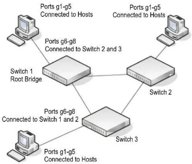
flowchart
graph TD
    A["Port g1-g5 Connected to Hosts"] --> B["Switch 1 Root Bridge"]
    C["Port g6-g8 Connected to Switch 2 and 3"] --> B
    D["Port g1-g5 Connected to Hosts"] --> E["Switch 2"]
    F["Port g6-g8 Connected to Switch 1 and 2"] --> G["Switch 3"]
    H["Port g1-g5 Connected to Hosts"] --> G
Perform the following procedures on each switch to configure MSTP:
- Use the VLAN Configuration screen to create VLANs 300 and 500 (see VLAN Configuration on page 89).
- Use the VLAN Membership screen to include ports g1–g8 as tagged (T) or untagged (U) members of VLAN 300 and VLAN 500 (see VLAN Membership Configuration on page 90).
- From the STP Configuration screen, enable the Spanning Tree State option (see STP Switch Configuration on page 100).
- In the Configuration Name field on the STP Configuration page, configure the name so that it is the same on each switch, for example netgear-stp. By default, the Configuration Name is the switch MAC address which means that it is unique for each switch.
- From the CST Configuration screen, set the Bridge Priority value for each of the three switches to force Switch 1 to be the root bridge:
- Switch 1: 4096
- Switch 2: 12288
- Switch 3: 20480
Note: Bridge priority values are multiples of 4096.
If you do not specify a root bridge and all switches have the same Bridge Priority value, the switch with the lowest MAC address is elected as the root bridge (see CST Configuration on page 102).
- From the CST Port Configuration screen, select ports g1–g8 and select Enable from the STP Status menu (see CST Port Configuration on page 103).
- Click Apply.
- Select ports g1–g5 (edge ports), and select Enable from the Fast Link menu.
Since the edge ports are not at risk for network loops, ports with Fast Link enabled transition directly to the Forwarding state.
- Click Apply.
You can use the CST Port Status screen to view spanning tree information about each port.
-
From the MST Configuration screen, create a MST instances with the following settings:
-
MST ID: 1
• Priority: Use the default (32768)
• VLAN ID: 300
For more information, see MST Configuration on page 107.
- Click Add.
-
Create a second MST instance with the following settings
-
MST ID: 2
-
Priority: 49152
• VLAN ID: 500 -
Click Add.
In this example, assume that Switch 1 has become the Root bridge for the MST instance 1, and Switch 2 has become the Root bridge for MST instance 2. Switch 3 has hosts in the Sales department (ports g1, g2, and g3) and in the HR department (ports g4 and g5).
Switches 1 and 2 also have hosts in the Sales and Human Resources departments. The host is used to find from MS Switzerland 2 to communicate with the
hosts on Switch 3 directly. Likewise, hosts of Switch 1 use VLAN 300, MST instance 1 to communicate with the hosts on Switch 3 directly.
The hosts use different instances of MSTP to effectively use the links across the switch. The same concept can be extended to other switches and more instances of MSTP.
Regulatory Compliance Information
This section includes user requirements for operating this product in accordance with National laws for usage of radio spectrum and operation of radio devices. Failure of the end-user to comply with the applicable requirements may result in unlawful operation and adverse action against the end-user by the applicable National regulatory authority.
This product's firmware limits operation to only the channels allowed in a particular Region or Country. Therefore, all options described in this user's guide may not be available in your version of the product.
FCC Requirements for Operation in the United States
FCC Information to User
This product does not contain any user serviceable components and is to be used with approved antennas only. Any product changes or modifications will invalidate all applicable regulatory certifications and approvals
This device complies with Part 15 of the FCC Rules. Operation is subject to the following two conditions: (1) This device may not cause harmful interference, and (2) this device must accept any interference received, including interference that may cause undesired operation.
FCC Guidelines for Human Exposure
This equipment complies with FCC radiation exposure limits set forth for an uncontrolled environment. This equipment should be installed and operated with minimum distance of 20 cm between the radiator and your body.
This transmitter must not be co-located or operating in conjunction with any other antenna or transmitter.
FCC Declaration Of Conformity
We, NETGEAR, Inc., 350 East Plumeria Drive, San Jose, CA 95134, declare under our sole responsibility that the GS716T and GS724T Gigabit Smart Switches complies with Part 15 of FCC Rules.
Operation is subject to the following two conditions:
- This device may not cause harmful interference, and
- This device must accept any interference received, including interference that may cause undesired operation.
FCC Radio Frequency Interference Warnings & Instructions
This equipment has been tested and found to comply with the limits for a Class B digital device, pursuant to Part 15 of the FCC Rules. These limits are designed to provide reasonable protection against harmful interference in a residential installation. This equipment uses and can radiate radio frequency energy and, if not installed and used in accordance with the instructions, may cause harmful interference to radio communications. However, there is no guarantee that interference will not occur in a particular installation.
If this equipment does cause harmful interference to radio or television reception, which can be determined by turning the equipment off and on, the user is encouraged to try to correct the interference by one or more of the following methods:
- Reorient or relocate the receiving antenna.
- Increase the separation between the equipment and the receiver.
- Consult the dealer or an experienced radio/TV technician for help.
- Connect the equipment into an electrical outlet on a circuit different from that which the radio receiver is connected.
Modifications made to the product, unless expressly approved by NETGEAR, Inc., could void the user's right to operate the equipment.
Canadian Department of Communications Radio Interference Regulations
This digital apparatus, GS716T and GS724T Gigabit Smart Switches, does not exceed the Class B limits for radio-noise emissions from digital apparatus as set out in the Radio Interference Regulations of the Canadian Department of Communications.
This Class [B] digital apparatus complies with Canadian ICES-003.
The GS716T and GS724T Gigabit Smart Switches complies with essential requirements of EU EMC Directive 2004/108/EC and Low Voltage Directive 2006/95/EC as supported by applying the following test methods and standards:
• EN55022: 2006 / A1: 2007
• EN55024: 1998 / A1: 2001 / A2 : 2003
• EN60950-1: 2005 2nd Edition
• EN 61000-3-2:2006
• EN 61000-3-3:1995 w/A1: 2001+A2: 2005
GPL License Agreement
GPL may be included in this product; to view the GPL license agreement go to
ftp://downloads.netgear.com/files/GPLnotice.pdf
For GNU General Public License (GPL) related information, visit
http://support.netgear.com/app/answers/detail/a_id/2649
Index
Numerics
802.1AS 145
global settings 145
port role 148
port settings 147
statistics 149
802.1X 175, 194
example configuration 290
A
access control
ACL example configuration 282
ACLs 209
management interface 185
Wizard 210
ACL Wizard 210
authentication
802.1X 193, 290
enable 28
list 184
port-based 193
RADIUS 175, 177
SNMP 28, 61, 62
TACACS+ 181
Auto-Video Configuration 112
Auto-VoIP Configuration 98
C
certificate 188
changing the password 18, 174
Class A traffic 134
Class B traffic 134
clock, grandmaster 145
compliance 297
Configuration
802.1X 194
Access Control Lists 209
Access Profile 190
Access Rule 192
Authentication List 184
Class 161, 164
Community 58
CoS 152
DHCP Filtering 76
Differentiated Services 159
DiffServ 160
DNS 47
Dual Image 261
Dynamic Address 130
Dynamic Host 49
Global 114
Green Ethernet 50, 51, 52
HTTP 186
IGMP Snooping 113
LACP 87
LACP Port 88
LAG 84
LLDP 63
MAC Filter 200
Management Access 185
MST Port 109
Network Settings on the Administrative System 15
password 174
Policy 167
Port Security 204
RADIUS 175
Global 175
Secure HTTP 187
SNMP v3 User 62
SNTP Server 42
Standard IP ACL Example 284
STP 99
TACACS+ 181
Time 39
Trap 60
VLAN 89
VLAN example 281
VLAN Port Membership 90
CoS 152
D
defaults 273
CoS 284
factory 174
DES 28
Device View 26
DHCP
client 11
Filtering 76
Filtering Interface Configuration 77
refreshing the client 17
DiffServ 159
DNS 47
DoS 44
download
a file 258
files via HTTP 257
from a remote system 257
software 257
Dual Image Status 263
E
EAP 240
EAPOL 240
F
failure codes 140
file management 261
firmware 20
firmware download 257
G
getting started 10
grandmaster clock 145
Green Ethernet 50, 51, 52
guest VLAN configuration 291
H
help, HTML-based 25
HTTP 186
management interface access 16
secure 185
using to download files 256, 260
HTTPS 187
|
ICMP 46
IEEE 802.11x 290
IEEE 802.1AB 63
IEEE 802.1AS 145
IEEE 802.1D 99
IEEE 802.1Q 89, 99
IEEE 802.1Qav 141
IEEE 802.1s 99
IEEE 802.1w 99
IEEE 802.1X 175
IEEE 802.3 flow control 82
IGMP 113
interface
LAG 83
logical 29
naming convention 29
physical 29
queue configuration 155
IP address
administrative system 15
switch 11, 33
IP DSCP 152
Mapping 158
IPv6
network interface 35
IPv6 network
configuration 36
IPv6 Network Configuration 35
IPv6 Network Interface IPv6 Neighbor Table 37
IPv6 Network Neighbor 37
L
LACP port configuration 88
LAG VLAN 83
LAGPDUs 83
LAGs 83
Membership 85
Static 83
listener, MSRP 132
LLDP 63
Local Information 68
neighbors information 72
packets 64
port settings 65
LLDP-MED 63
M
MAC 33, 70, 105, 113
ACL 211
bridge identifier 108
CPU Management Interface 29
dynamic address 130
filter summary 202
MFDB Table 118
multicast destination 118
rules 212
searching address table 128
Static Address 131
MAC ACL 211
MD5 39
MIBs 28
MMRP
definition 132
statistics 135
MRP
global settings 133
port settings 134
MSRP
definition 132
reservation parameters 139
statistics 137
streams 143
Multiple Registration Protocol 132
N
navigation 24
0
OUI 96
P
password
change 18, 174
login 174
Ping 264
port
authentication 193
summary 198
port role, 802.1AS 148
Precision Time Protocol 145
product registration 271
Q
Qav
definition 141
global settings 141
QoS 151
802.1p to Queue Mapping 156
R
RADIUS 173
server 175
statistics 178
VLAN assignment 194
reboot 17, 253
registration
disabling 271
product 271
serial number 271
reset
button 174
configuration to defaults 254
switch 253
RSTP 99
S
Security MAC Address 207
server, HTTP 186
severity, log message 244
Simple Network Time Protocol 38
SNMP 58
traps 60
using 28
v1, v2 58
v3 62
SNTP 38
Global Status 40
global status 40
server configuration 42
server status 43
specifications 273
SSL 187
storm control 203
STP 99
example configuration 293
Status 100
Stratum
0 38
1 38
2 38
streams, MSRP 139
T
T1 39
T2 39
T3 39
T4 39
TACACS+
folder 181
settings 181
talker, MSRP 132
technical support 2
Time
configure through SNTP 40
UTC 40
time 38
clock source 40
levels 38
local 40
zone 40
TraceRoute 267
GS716T and GS724T Gigabit Smart Switches
trademarks 2
traffic control 200
trap
flags 61
manager 61
TSpec 144
U
Unicast 39
upload configuration 255
V
VLAN 89
example configuration 279
guest 194, 196, 290
ID 89
management 34
managing 89
RADIUS-based assignment 194
voice 94
Voice VLAN OUI 96
VoIP 97, 98
W
Web interface panel 23

- Gigabit Smart Switches
- Software Administration Manual
- Technical Support
- Statement of Conditions
- Contents
- Chapter 1 Switch Information and Setup
- Chapter 2 System Information Features
- GS716T and GS724T Gigabit Smart Switches
- Chapter 3 Switching Features
- Chapter 4 Quality of Service Features
- Chapter 5 Device Security
- Chapter 6 Monitoring the System
- Chapter 7 Maintenance
- Chapter 8 Help
- Appendix A Hardware Specifications and Default Values
- Appendix B Configuration Examples
- Appendix C Notification of Compliance
- Document Organization
- GS716T and GS724T Smart Switch Setup
- Switch Management Interface
- Connecting the Switch to the Network
- Switch Discovery in a Network with a DHCP Server
- Switch Discovery in a Network without a DHCP Server
- Network Settings Configuration on the Administrative System
- WARNING:
- Web Access
- Smart Control Center Utilities
- Network Utilities
- Configuring the Device
- Changing the Switch Password
- Configuration Upload and Download
- Firmware Upgrade
- Viewing and Managing Tasks
- User Interfaces
- Web Interface
- Navigation Tabs, Feature Links, and Page Menu
- Configuration and Status Options
- Device View
- Help Page Access
- User-Defined Fields
- SNMP Management
- Interface Naming Convention
- System Information Features
- 2
- Management
- System Information
- IP Configuration
- IPv6 Network Configuration
- IPv6 Network Neighbor
- Time
- Time Configuration
- SNTP Server Configuration
- Denial of Service
- Auto-DoS Configuration
- DoS Configuration
- DNS
- DNS Configuration
- Host Configuration
- Green Ethernet
- Green Ethernet Configuration
- Green Ethernet Interface Configuration
- Green Ethernet Detail
- Green Ethernet Statistics Summary
- License
- Show License
- License Features
- SNMP
- SNMPV1/V2
- Community Configuration
- Trap Configuration
- Trap Flags
- SNMP v3 User Configuration
- LLDP
- LLDP Configuration
- LLDP Port Settings
- LLDP-MED Network Policy
- LLDP-MED Port Settings
- Local Information
- Neighbors Information
- Services — DHCP Filtering
- DHCP Filtering Configuration
- Interface Configuration
- Ports
- Port Configuration
- Flow Control
- Link Aggregation Groups
- LAG Configuration
- LAG Membership
- LACP Configuration
- To configure LACP:
- LACP Port Configuration
- VLANs
- VLAN Configuration
- VLAN Membership Configuration
- Port VLAN ID Configuration
- Voice VLAN
- Voice VLAN Properties
- Voice VLAN Port Setting
- Voice VLAN OUI
- Auto-VoIP Configuration
- To enable Auto-VoIP:
- Spanning Tree Protocol
- STP Switch Configuration
- CST Configuration
- CST Port Configuration
- CST Port Status
- Rapid STP
- MST Configuration
- MST Port Configuration
- STP Statistics
- Multicast
- Auto-Video Configuration
- IGMP Snooping
- IGMP Snooping Configuration
- IGMP Snooping Interface Configuration
- IGMP Snooping Table
- Multicast Forwarding Database Table
- MFDB Statistics
- IGMP Snooping VLAN Configuration
- Multicast Router Configuration
- Multicast Router VLAN Configuration
- IGMP Snooping Querier
- IGMP Snooping Querier Configuration
- IGMP Snooping Querier VLAN Configuration
- IGMP Snooping Querier VLAN Status
- Address Table
- MAC Address Table
- Dynamic Address Configuration
- Static MAC Address
- Multiple Registration Protocol Configuration 1
- MRP Configuration
- MRP Port Settings
- MMRP Statistics
- MSRP Statistics
- MSRP Reservation Parameters
- Qav Parameters
- MSRP Streams Information
- 802.1AS 1
- 802.1AS Configuration
- 802.1AS Port Settings
- 802.1AS Statistics
- Class of Service
- Basic CoS Configuration
- CoS Interface Configuration
- Interface Queue Configuration
- 802.1p to Queue Mapping
- DSCP to Queue Mapping
- Differentiated Services
- Defining DiffServ
- DiffServ Configuration
- Class Configuration
- IPv6 Class Configuration
- Policy Configuration
- Service Configuration
- Service Statistics
- Management Security Settings
- Change Password
- RADIUS Configuration
- Global Configuration
- RADIUS Server Configuration
- Accounting Server Configuration
- Configuring TACACS+
- TACACS+ Configuration
- TACACS+ Server Configuration
- Authentication List Configuration
- Configuring Management Access
- HTTP Configuration
- Secure HTTP Configuration
- Certificate Download
- Downloading SSL Certificates
- Access Profile Configuration
- Access Rule Configuration
- Port Authentication
- 802.1X Configuration
- Port Summary
- Traffic Control
- MAC Filter Configuration
- MAC Filter Summary
- Storm Control
- Port Security Configuration
- Port Security Interface Configuration
- Security MAC Address
- Protected Ports Membership
- Configuring Access Control Lists
- ACL Wizard
- MAC ACL
- MAC Rules
- MAC Binding Configuration
- MAC Binding Table
- IP ACL
- IP Rules
- IP Extended Rules
- IPv6 ACL
- IPv6 Rules
- IP Binding Configuration
- IP Binding Table
- Switch Statistics
- Port Statistics
- Port Detailed Statistics
- EAP Statistics
- System Logs
- Memory Logs
- FLASH Log Configuration
- Server Log Configuration
- Trap Logs
- Event Logs
- Port Mirroring
- Multiple Port Mirroring
- Reset
- Device Reboot
- Factory Default
- Upload File From Switch
- TFTP File Upload
- HTTP File Upload
- Download File To Switch
- TFTP File Download
- HTTP File Download
- File Management
- Dual Image Configuration
- Dual Image Status
- Troubleshooting
- Ping
- Ping IPv6
- Traceroute
- Online Help
- Support
- User Guide
- Registration
- Hardware Specifications and Default Values
- GS716T and GS724T Gigabit Smart Switches Specifications
- GS716T Specifications
- GS724T Specifications
- GS716T and GS724T Switch Features and Defaults
- Virtual Local Area Networks (VLANs)
- VLAN Example Configuration
- Access Control Lists (ACLs)
- MAC ACL Example Configuration
- Standard IP ACL Example Configuration
- Differentiated Services (DiffServ)
- Class
- DiffServ Traffic Classes
- Creating Policies
- Traffic Conditioning Policy
- DiffServ Example Configuration
- 802.1X
- 802.1X Example Configuration
- MSTP
- MSTP Example Configuration
- Regulatory Compliance Information
- FCC Requirements for Operation in the United States
- FCC Information to User
- FCC Guidelines for Human Exposure
- FCC Declaration Of Conformity
- FCC Radio Frequency Interference Warnings & Instructions
- Canadian Department of Communications Radio Interference Regulations
- GPL License Agreement
- Index
- Numerics
- A
- C
- D
- E
- F
- G
- H
- |
- L
- M
- MMRP
- MRP
- MSRP
- N
- 0
- P
- Q
- R
- S
- T
- U
- V
- W
Brand : NETGEAR
Model : GS716Tv2
Category : Uncategorized