
MIM-E02EN - Régulateur SAMSUNG - Free user manual and instructions
Find the device manual for free MIM-E02EN SAMSUNG in PDF.

| Brand | Samsung |
| Model | MIM-E02EN |
| Product Type | Communication Kit (Regulator) for EHS Heat Pump Outdoor Units |
| Power Supply | 12 V DC (from outdoor unit PCB via supplied cable) |
| Communication Protocol | Modbus (RS-485) |
| Compatible Outdoor Units | Samsung EHS 5 kW (MIM-E02EN) and 8/16 kW (MIM-E02FN) |
| Accessories Included | DC power cable (12 V), communication cable (ring terminal), communication cable (red connector), flow switch, mounting screw (M4), bracket |
| Configuration Interface | DIP switches SW4 and SW5 for device address, refrigerant type, flow switch usage |
| Status Indicators | LED: Y-GRN (outdoor communication), RED (indoor communication), YEL (not used); 7-segment display (program codes, normal operation, error codes) |
| Error Detection | Displays error codes (E101, E108, etc.) for communication, sensor, and hardware faults |
| Installation Requirements | Must be installed by qualified personnel; power off before wiring; use supplied cables; observe torque (0.5-0.75 N·m) for terminal block screws |
| Maximum Cable Length | 1000 m between control unit and farthest COMM KIT |
| Operating Environment | Avoid flammable gases, oil, vapor, sulfur dioxide, special sprays, acids/alkalis |
| Repair and Maintenance | Do not disassemble or modify; contact service center for repairs |
| Disposal | Contact service center for proper disposal |
Frequently Asked Questions - MIM-E02EN SAMSUNG
User questions about MIM-E02EN SAMSUNG
0 question about this device. Answer the ones you know or ask your own.
Ask a new question about this device
Download the instructions for your Régulateur in PDF format for free! Find your manual MIM-E02EN - SAMSUNG and take your electronic device back in hand. On this page are published all the documents necessary for the use of your device. MIM-E02EN by SAMSUNG.
USER MANUAL MIM-E02EN SAMSUNG
• Thank you for purchasing this Samsung Product.
- Before operating this unit, please read this installation manual carefully and retain it for future reference.

natural_image
Black and white photo of a large, ripple wave or ocean wave with visible waves crashing against the sky (no text or symbols)Safety Information
This installation manual explains how to install COMM KIT that connects control unit and outdoor unit. Please read this manual thoroughly before installing the product. (Please refer to appropriate installation for any optional product installation.)

WARNING
Hazards or unsafe practices that may result in severe personal injury or death.

CAUTION
Hazards or unsafe practices that may result in minor personal injury or property damage.
! Follow directions. Do NOT attempt
Make sure the machine is grounded to prevent electric shock.
Unplug the power plug from the wall socket.
Do NOT disassemble.
FOR INSTALLATION

WARNING
Consult qualified installer or service center for installation.
- If not, there is risk of product malfunction, water leakage, electric shock or fire.
Make sure to use the supplied cables.
- If not, there is risk of fire or damage to the product.
2 English


Make sure that all wiring work is done by qualified person complying regional standards and instructions in this manual.
- If the installation is done by unqualified person, there is risk of product malfunction, electric shock or fire caused by incorrect installation.
Check if the installation was done properly according to the installation manual.
- There is risk of electric shock or fire if the product is installed incorrectly.

CAUTION
Make sure there is no tension to the cable during installation.
- Cable may get cut and cause fire.
When installing the product in hospitals or other places, make sure that the product does not interrupt with other products.
- Abnormal operation may occur.
Do not install the product in a place where flammable gas leaks or if there is possible chance of leakage.
- There is risk of fire or explosion.
Do not install the product in a place where it will be exposed to oil or vapor etc.
- If the product is used in a place where it is exposed to oil, vapor or sulphur dioxide, parts of the product may get damaged or product may function abnormally.
Do not install the product in a place where special spray or acid/alkali solution is used.
- There is risk of electric shock or abnormal operation.
Safety Information
For operation

WARNING
Do not attempt to repair, disassemble, or modify the product yourself.
- There is potential risk of product damage, electric shock or fire. When repair is needed, consult qualified installer or service center.
Contact the service center when you need to dispose the product.
Do not attempt to move or re-install the product that is already installed.
- If not, there is risk of electric shock or fire.

CAUTION
Do not allow water to enter the product.
- If not, there is risk of electric shock or fire.
Do not connect the power cable to the communication cable terminal.
- There is risk of fire.
COMM KIT Installation
Accessories
| Item CO | MM KIT | DC power cable (12 V) | Communication cable | Flow switch | Screw (M4) Bracket | |
| Only for MIM-E02EN | ||||||
| Quantity | 11211 | 1 | ||||
| Shape | 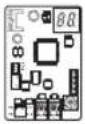 |  |  | 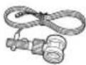 | ### | 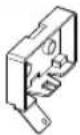 |
Diagram of connection between COMM KIT and outdoor unit
MIM-E02EN (5kW Outdoor Unit)
natural_image
Diagram of a mechanical or electrical component with an arrow indicating assembly or connection (no text or symbols present)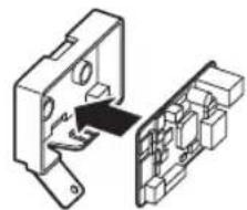
natural_image
Diagram of a mechanical assembly with an arrow pointing to a component (no text or symbols present)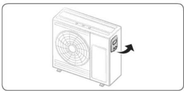
natural_image
Line drawing of a single air conditioner unit with fan blades and control panel (no text or symbols)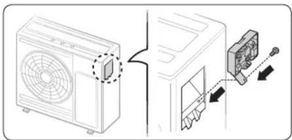
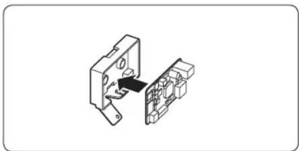
- Fix the COMM KIT PBA at case.
- Open the control cover of the outdoor unit (5kW).
- Mount the COMM KIT on the COMM KIT CASE with 1 screw noting the assembly direction.
English 5
COMM KIT Installation
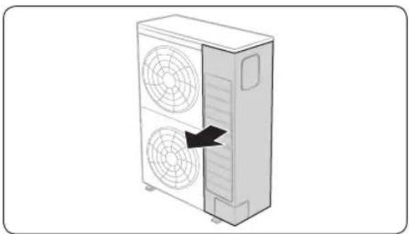
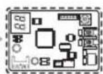
MIM-E02FN (8/16kW Outdoor Unit)
natural_image
Diagram of a dual air conditioning unit with fan blades, showing internal airflow direction (no text or symbols)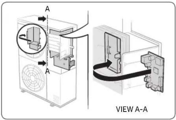
-
Open the right hand of the front cabinet of outdoor unit (8/16kW).
-
Mount the COMM KIT on the case's EMI fixing hooks noting the assembly direction. (Attach the COMM KIT and the terminal of PCB DC power cable to be on the left side.)
6 English
Connecting COMM KIT to the outdoor unit
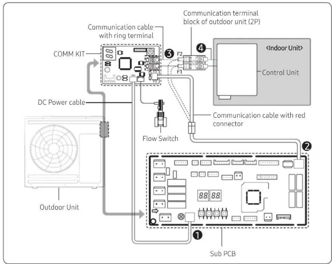
MIM-E02EN (5kW Outdoor Unit)
- Connect the DC power cable connector (Blue) to CN303 of SUB PCB in the EHS outdoor unit by using a DC power cable.
- Disconnect the F1 and F2 wires from the terminal block in the outdoor unit. Then, connect the disconnected cable to a communication cable with red connector, and connect it to the communication connector of the COMM KIT.
- Connect the F1-F2 terminal block to the communication block of the COMM KIT, by using the communication cable with the ring terminal.
- Connect the communication cable from the indoor unit to the F1 and F2 terminal blocks in the outdoor unit.
flowchart
graph TD
    A["Outdoor Unit"] --> B["DC Power cable"]
    B --> C["COMM KIT"]
    C --> D["Communication cable with ring terminal"]
    D --> E["F1"]
    E --> F["Communication terminal block of outdoor unit (2P)"]
    F --> G["F2"]
    G --> H["<Indoor Unit> Control Unit"]
    H --> I["Flow Switch"]
    I --> J["Communication cable with red connector"]
    J --> K["Sub PCB"]
    style A fill:#f9f,stroke:#333
    style H fill:#ccf,stroke:#333
English 7
COMM KIT Installation
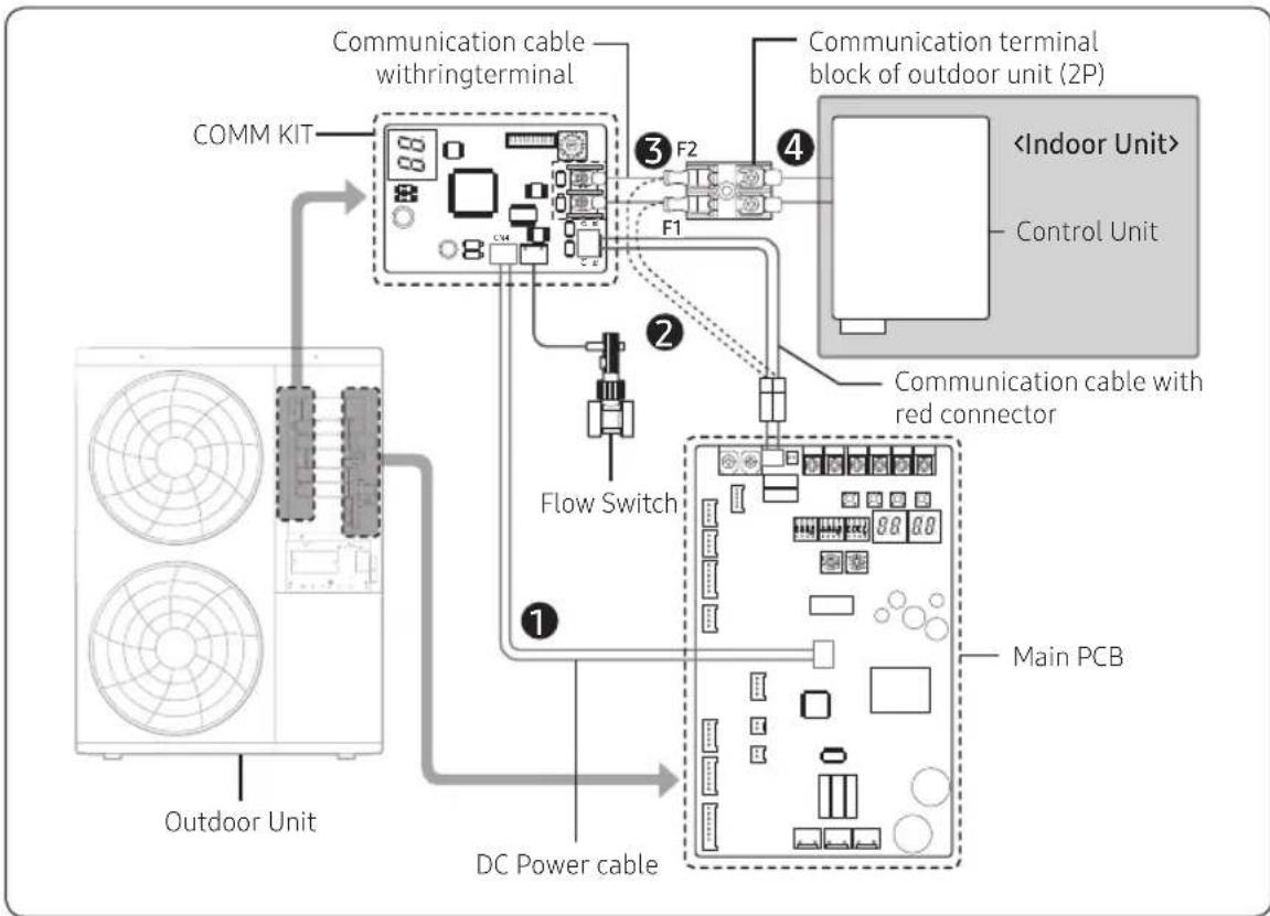
MIM-E02FN (8/16kW Outdoor Unit)
- Connect the DC power cable connector (Blue) to CN12 of Main PCB in the EHS outdoor unit by using a DC power cable.
- Disconnect the F1 and F2 wires from the terminal block in the outdoor unit. Then, connect the disconnected cable to a communication cable with red connector, and connect it to the communication connector of the COMM KIT.
- Connect the F1-F2 terminal block to the communication block of the COMM KIT, by using the communication cable with the ring terminal.
- Connect the communication cable from the indoor unit to the F1 and F2 terminal blocks in the outdoor unit.
flowchart
graph TD
    A["COMM KIT"] --> B["Communication cable withringterminal"]
    B --> C["Flow Switch"]
    C --> D["DC Power cable"]
    D --> E["Main PCB"]
    F["Communication terminal block of outdoor unit (2P)"] --> G["Control Unit"]
    G --> H["Communication cable with red connector"]
    H --> I["Main PCB"]
    J["Outdoor Unit"] --> A
    style A fill:#f9f,stroke:#333
    style B fill:#ccf,stroke:#333
    style C fill:#cfc,stroke:#333
    style D fill:#fcc,stroke:#333
    style E fill:#cff,stroke:#333
    style F fill:#ffc,stroke:#333
    style G fill:#fcc,stroke:#333
    style H fill:#ffc,stroke:#333
    style I fill:#fcc,stroke:#333
CAUTION
- The control unit terminal block of COMM KIT (MIM-E02EN / MIM-E02FN) must be fixed with M3 sized screws, and its torque must be 0.5 to 0.75 N·m.
- The cable length between the control unit and the farthest COMM KIT must be within 1000 m.
- Be sure to switch off the power supply before installation.
- Wiring should be performed in accordance with the electric wiring regulations and must be placed in the wall so that users cannot touch them.
8 English
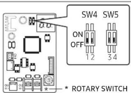
Setting option switch
: No need of separate settings
How to set option switches
| Settings | Dip S/W(SW4) Dip S/W(SW5) | |||
| 1 2 3 4 | ||||
| ON - Device 31 | Not using Flow Switch | R-410A Model | ||
| OFF | Modbus Communication | Device 30 | Using Flow Switch | R-32 Model |
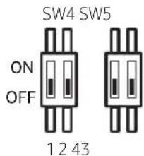
- The initial settings for option switches are OFF in SW 4 and SW 5.
- When operating two outdoor units with a single control unit, set No.2 of SW4 differently. (UNIT 1 OFF → Device 30, UNIT 2 ON → Device 31)
Example)
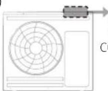
natural_image
Simple line drawing of a fan or air conditioner unit with a dashed arrow pointing to the top-right corner (no text or symbols)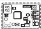
COMM KIT DIPS/W
SW4 #2 : ON

COMM KIT DIP S/W
SW4 #2 : OFF
OUTDOOR UNIT 2
- In order to change the setting of the option switch, reset the power of COMM KIT.
English 9
Checking Operation
LED Display
- When you reset the power supply and find that the communication between the COMM KIT and outdoor unit is valid, the Y-GRN LED blinks. (Please wait until the communication between the COMM KIT and the outdoor unit becomes normal.)
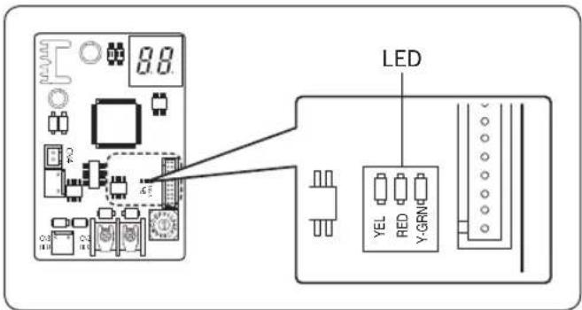
- When the communication between the COMM KIT and indoor unit is detected as valid, the RED LED blinks.

NOTE
- YEL LED is not in use.
10 English
7-SEGMENT display
- When the power supply is initialized, the program codes appear.
• Examples of the program code: 17 89 A3 16
- Then the tracking of COMM KIT will proceed as the following:
• Display in normal operation
- If the value of the register number 40011 is 0 or there is no signal, "A" and "0" appear on the first and second segments for 1 second.
→ Displays "3" and "0" or "1" for 1 second. (A030 device's 30-Dip S/W #2 is OFF, A031 device's 31-Dip S/W #2 is ON.)
- If the value of the register number 40011 is not 0, "A" is displayed on the first segment, and the hundreds digit number of the register is displayed on the second segment for 1 second.
→ The tens digit number is displayed on the first segment, and the unit digit number is displayed on the second segment for 1 second.
Example)
| REGISTER NUMBER(#40011) DIP SWITCH(#2) SEGMENT | |
| 0 (or no entry) OFF | |
| 100 - |
| 255 - | 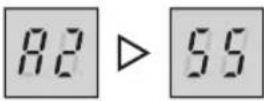 |
• Display when an error occurs
- "E" and "*" are displayed on the first and second segments for 1 second. → Displays "*" and "*" for 1 second. (This action will repeat until the error is corrected)
Example)
| ERROR CODE SEGMENT | |
| E101 | 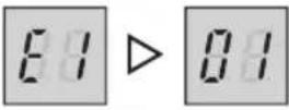 |
English 11
Error Codes
If the unit has some problems and does not work normally, error code is shown on the OUTDOOR UNIT MAIN PCB.
| Display Explanation Error Source | ||
| E101 | Communication error between the indoor and outdoor units (when indoor unit cannot receive signals) | COMM KIT OUTDOOR UNIT |
| E108 | Duplicate channel addresses - overlapping of unit channel addresses on a system. | OUTDOOR UNIT |
| E109 Communication error due to indoor unit address incomplete. | COMM KIT OUTDOOR UNIT | |
| E111 | Modbus communication error (when COMM KIT cannot receive signals) | COMM KIT OUTDOOR UNIT |
| E162 EEPROM H/W ERROR COMM KIT | ||
| E177 Emergency Error | COMM KIT OUTDOOR UNIT | |
| E201 | COMM KIT/OUTDOOR UNIT communication error (Matching error) | OUTDOOR UNIT |
| E202 COMM KIT/OUTDOOR UNIT communication error (3 min) OUTDOOR UNIT | ||
| E203 Communication error between INVERTER and MAIN MICOM (6 min) OUTDOOR UNIT | ||
| E221 OUTDOOR UNIT temperature sensor error OUTDOOR UNIT | ||
| E231 Condenser temperature sensor error OUTDOOR UNIT | ||
| E251 Discharge temperature sensor error OUTDOOR UNIT | ||
| E320 OLP sensor error OUTDOOR UNIT | ||
| E403 | Detection of OUTDOOR UNIT compressor freezing (During cooling operation) | OUTDOOR UNIT |
| E404 | Protection of OUTDOOR UNIT when it is overload (during Safety Start, Normal operation state) | OUTDOOR UNIT |
| E407 Comp down due to high pressure OUTDOOR UNIT | ||
| E416 Discharge of a compressor is overheated OUTDOOR UNIT | ||
| E425 | Power source line missing error (only for 3-phase model) | OUTDOOR UNIT |
| E440 | Heating operation blocked (outdoor temperature over 35°C) | OUTDOOR UNIT |
| E441 | Cooling operation blocked (outdoor temperature under 9°C) | OUTDOOR UNIT |
| E458 | OUTDOOR UNIT fan1 error | OUTDOOR UNIT |
| E461 [Inverter] Compressor startup error OUTDOOR UNIT | ||
12 English
| Display Explanation Error Source | ||
| E462 [Inverter] Total current error/PFC over current error OUTDOOR UNIT | ||
| E463 OLP is overheated OUTDOOR UNIT | ||
| E464 [Inverter] IPM over current error OUTDOOR UNIT | ||
| E465 Compressor V limit error OUTDOOR UNIT | ||
| E466 DC LINK over/low voltage error OUTDOOR UNIT | ||
| E467 [Inverter] Compressor rotation error OUTDOOR UNIT | ||
| E468 [Inverter] Current sensor error OUTDOOR UNIT | ||
| E469 [Inverter] DC LINK voltage sensor error OUTDOOR UNIT | ||
| E470 Outdoor unit EEPROM Read/Write Error OUTDOOR UNIT | ||
| E471 Outdoor unit EEPROM Read/Write Error(OTP error) OUTDOOR UNIT | ||
| E474 | IPM(IGBT Module) or PFCM temperature sensor Error | OUTDOOR UNIT |
| E475 OUTDOOR UNIT fan2 error OUTDOOR UNIT | ||
| E483 H/W DC_Link Over Voltage Error OUTDOOR UNIT | ||
| E484 | PFC Overload Error | OUTDOOR UNIT |
| E485 | Input current sensor error | OUTDOOR UNIT |
| E488 | AC Input Voltage Sensor Error | OUTDOOR UNIT |
| E500 | IPM is overheated | OUTDOOR UNIT |
| E554 | Gas leak error | OUTDOOR UNIT |
| E590 | Inverter EEPROM CheckSum Error | OUTDOOR UNIT |
| E901 | Water inlet (PHE) temperature sensor error(open/short) | OUTDOOR UNIT |
| E902 | Water outlet (PHE) temperature sensor error(open/short) | OUTDOOR UNIT |
| E906 | Refrigerant gas inlet (PHE) temperature sensor (open/short) | OUTDOOR UNIT |
| E911 Flow Swtich Open Error COMM KIT | ||
English 13


MEMO


Installation
14 English


Installation
English 15


- Safety Information
- WARNING
- CAUTION
- FOR INSTALLATION
- For operation
- COMM KIT Installation
- Diagram of connection between COMM KIT and outdoor unit
- Connecting COMM KIT to the outdoor unit
- MIM-E02EN (5kW Outdoor Unit)
- MIM-E02FN (8/16kW Outdoor Unit)
- Setting option switch
- How to set option switches
- Checking Operation
- LED Display
- NOTE
- 7-SEGMENT display
- Error Codes
- MEMO
Brand : SAMSUNG
Model : MIM-E02EN
Category : Régulateur