
PC Ground Station - Uncategorized DJI - Free user manual and instructions
Find the device manual for free PC Ground Station DJI in PDF.


| Product Type | Ground Station Module |
| Brand | DJI |
| Model | PC Ground Station |
| Dimensions (approx.) | 100 x 80 x 30 mm |
| Weight (approx.) | 150 g |
| Power Input | 5 V DC via USB |
| Power Consumption | 2.5 W (typical) |
| Operating Frequency | 2.4 GHz - 2.4835 GHz |
| Max Transmission Range | Up to 5 km (unobstructed) |
| Compatibility | Windows 7/8/10, macOS 10.12+ |
| Main Functions | Real-time telemetry, waypoint planning, virtual joystick, firmware updates |
| Data Interface | USB 2.0, UART |
| Antenna Type | Detachable dipole antenna (RP-SMA) |
| Operating Temperature | 0 °C to 40 °C |
| Storage Temperature | -20 °C to 60 °C |
| Humidity | 5% - 95% (non-condensing) |
| Maintenance | Clean with soft, dry cloth. Avoid moisture and dust. |
| Safety Precautions | Do not expose to extreme temperatures. Use only provided cables. |
| Spare Parts Available | Antenna, USB cable, mounting bracket (sold separately) |
| Warranty | 1 year limited warranty |
Frequently Asked Questions - PC Ground Station DJI
User questions about PC Ground Station DJI
0 question about this device. Answer the ones you know or ask your own.
Ask a new question about this device
Download the instructions for your Uncategorized in PDF format for free! Find your manual PC Ground Station - DJI and take your electronic device back in hand. On this page are published all the documents necessary for the use of your device. PC Ground Station by DJI.
USER MANUAL PC Ground Station DJI
Ground Station Wireless Data-link User Manual
V 3.02
2014.11 Revision

Disclaimer
Thank you for purchasing product(s) in DJI Innovations. Please strictly follow these steps to install all the software and hardware products, and make sure your Ground Station and Wireless Data-link work perfectly. Please use the wireless data-link in accordance with the provisions of the local radio control. DJI Innovations assumes no liability for damage(s) or injured incurred directly or indirectly from the use of this product. As DJI Innovations has no control over use, setup, final assembly, modification (including use of non-specified
DJI parts i.e. motors, ESCs, propellers, etc.) or misuse, no liability shall be assumed nor accepted for any resulting damage or injury. By the act of use, setup or assembly, the user accepts all resulting liability. DJI Innovations assumes no liability for damage(s) or injured incurred directly or indirectly from the use of this product.
Google logo is a registered trademark of Google Inc. DJI is a registered trademark of DJI Innovations. Names of products, brands, etc., appearing in this manual are trademarks or registered trademarks of their respective owner companies. This product and manual are copyrighted by DJI Innovations with all rights reserved. No part of this product or manual shall be reproduced in any form without the prior written consent or authorization of DJI Innovations. No patent liability is assumed with respect to the use of the product or information contained herein.
Profile
Please read this instruction thoroughly for proper operation of your new DJI Ground Station and Wireless Data-link. Full featured DJI Ground Station enables 3-D Map Way Points Editing, Flight Path Planning, Real-time Flight State Feedback and Auto Takeoff and Landing. This product is specially designed for the purpose of aircraft operation, BVR (Beyond Visual Range) flying in applications such as surveillance, aerial photography, etc. Working with DJI flight control system, DJI Ground Station not only ensures stable performance and safety of the aircraft, easy operation for the pilot, but also allows the aircraft to fly along the flight path set before or modified during the flight mission in the Ground Station software autonomously. This manual covers both Single Waypoint and Ground Station products. Read this manual according to your product package. E.g., if you have ACE Single Waypoint, then you do not need to read section 4.4. Please refer to DJI flight control system manual for semi-auto takeoff and landing.
| Production | ACE | WKM | A2 | NAZA-M/ NAZA-M V2 | Phantom 2 | |||
| Product packages | View Mode | Joystick /Keyboard Mode | Single Waypoint | Ground Station | Ground Station | Ground Station | Ground Station | Ground Station |
| 3D MapDisplay | ● | ● | ● | ● | ● | ● | ● | ● |
| Real-time Flight Monitoring | ● | ● | ● | ● | ● | ● | ● | ● |
| Flight Simulation | ● | ● | ● | ● | ● | ● | ● | |
| One Key Takeoff | ● | ● | ● | ● | ||||
| Joystick / Keyboard Mode | ● | ● | ● | ● | ● | ● | ● | |
| One Key Go Home | ● | ● | ● | ● | ● | ● | ||
| Click Go Mode | ● | ● | ● | ● | ● | ● | ||
| Waypoints Editing | 200 Waypoints | 50 Waypoints | 50 Waypoints | 16 Waypoints | 16 Waypoints | |||
| Automatic Takeoff & Landing | ● | ● | ● | ● | ● | |||
| F Channel Controller | ● | ● | ● | ● | ||||
| General Purpose Servo Action | ● | ● | ● | ● | ||||
| Six Route Templates | ● | ● | ● | ● | ● | |||
| Photogrammetry Tool | ● | ● | ● | ● | ||||
In Box
Wireless Data-link Ground End × 1
It connects to your computer. Computer sends commands and
receives flight data through it

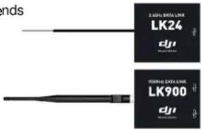
Wireless Data-link Air End 900MHz × 1 or 2.4GHz × 1
It connects to DJI autopilot system. Flight control system sends
flight data and receives commands from computer by it.
USB Cable × 1
For connection between wireless data-link ground end and computer.
4-Pin Cable × 1
For connection between wireless data-link air end and flight control system.
Warranty Card × 1
It recommends the necessary conditions for using this system and related safety issues. Please fill out the customer & information card and return to DJI Innovations to register your product warranty.
Contents
Disclaimer - 2 -
Profile.... - 2 -
In Box.... - 4 -
Contents.... - 5 -
Matters Need Attention.... - 6 -
Connection.... - 7 -
Ground Station Software ....- 8 -
Install Software.... - 8 -
Start Software ...... - 9 -
Application ...... - 9 -
Control Mode Switch - 10 -
GUI - 11 -
1 View Mode ...... - 14 -
1.1 View Mode Procedures.... - 14 -
1.2 System Setting.... - 14 -
2 Joystick/Keyboard Mode.... - 18 -
2.1 Simulator.... - 18 -
2.2 One Key Takeoff - 19 -
2.3 Joystick and Keyboard Mode.... - 20 -
3 Click Go Mode.... - 22 -
4 Waypoint(Single Waypoint User Skip This).... - 24 -
4.1 Waypoint Mode - 24 -
(I) Flight Mission Setting.... - 27 -
(II) Upload Flight Mission.... - 31 -
(III) Take off Aircraft.... - 31 -
(IV) Switch to Autopilot Mode - 31 -
(V) GO!! - 32 -
4.2 Auto Takeoff and Landing.... - 33 -
4.3 F Channel Controller - 34 -
4.4 General Purpose Servo Action (GP-Servo Action) - 36 -
4.5 Six Pre-Programmed Route Templates.... - 39 -
4.6 Photogrammetry Tool - 40 -
Appendix.... - 42 -
List of Ground Station Shortcut Keys .... - 42 -
Troubleshooting - 43 -
Data-link LED Introduction.... - 46 -
Wireless Data-link Specification.... - 47 -
Flight Limit of Special Areas - 48 -
Matters Need Attention
- The ability of penetrating of radio signal from 2.4GHz wireless data-link is weak; please make sure the antenna of it is always visible to the ground end during the flight. Human body, trees, buildings or hills will stop the communication between air end and ground end.
- You'd better put the ground end at high place. This can guarantee a good communication range.
- Make sure the antenna head of air end is erect down, and the antenna head of ground end is erect up. Make sure there is no obstacle between antennas; otherwise the communication range will be reduced.
- Ground end Link-Alarm red light on is distance alarm, red light off is safe. When it is on, you'd better return your aircraft.
- When ground end Link-Alarm green light is off, this indicates the communication between ground end and air end is off, whatever the state of red light.
- Make sure the driver is installed correctly.
- Please choose the right com port.
- Check out the power supply of wireless data-links before use.
- Please close the DJI assistant software before open the ground station. Otherwise there will be port conflict.
- Make sure the distance between 2.4GHz ground end and air end is over 1.5m; the distance between 900MHz ground end and air end is over 5m.
- Use the right cable for connection.
- High voltage servos & FBL systems can drain the flight battery fast. Please make sure your flight pack is sufficient for the flight time intended.
- About control modes (Manual, Atti., GPS Atti., GPS Cruise), please refer to ACE Control Modes in ACE Waypoint User Manual and Control Modes in A2/WKM/NAZA-M/NAZA-M V2/ Phantom 2 User Manual.
- Autopilot Mode (auto mode) means: GPS Atti. or GPS Cruise Mode in ACE; GPS Atti. Mode in A2/WKM/NAZA-M/NAZA-M V2; Ready to fly in Phantom 2.
If you have any problem you cannot solve during installation and usage, please contact our customer service.
Connection
flowchart
graph TD
    A["Ground Station"] --> B["Communication Interface"]
    B --> C["Power Interface"]
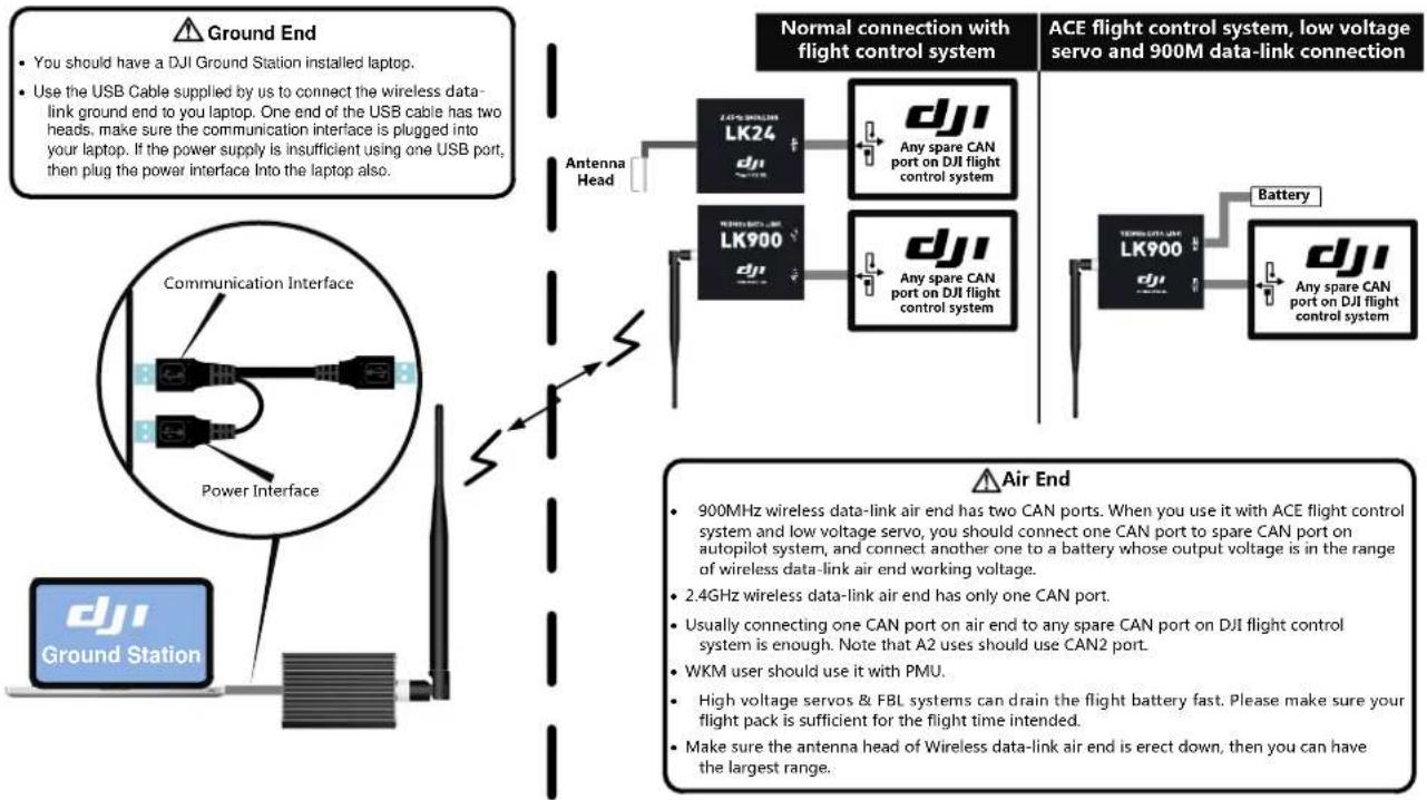
    D["Ground End"] --> E["Use the USB Cable supplied by us to connect the wireless data-link ground end to you laptop. One end of the USB cable has two heads, make sure the communication interface is plugged into your laptop. If the power supply is insufficient using one USB port, then plug the power interface into the laptop also."]
    E --> F["Antenna Head"]
    F --> G["LK24"]
    F --> H["LK900"]
    G --> I["Any spare CAN port on DJI flight control system"]
    H --> J["Any spare CAN port on DJI flight control system"]
    I --> K["ACE flight control system, low voltage servo and 900M data-link connection"]
    J --> L["Battery"]
    K --> M["Air End"]
    L --> M
    M --> N["900MHz wireless data-link air end has two CAN ports. When you use it with ACE flight control system and low voltage servo, you should connect one CAN port to spare CAN port on autopilot system, and connect another one to a battery whose output voltage is in the range of wireless data-link air end working voltage."]
    M --> O["2.4GHz wireless data-link air end has only one CAN port."]
    O --> P["Usually connecting one CAN port on air end to any spare CAN port on DJI flight control system is enough. Note that A2 uses should use CAN2 port."]
    P --> Q["WKM user should use it with PMU."]
    Q --> R["High voltage servos & FBL systems can drain the flight battery fast. Please make sure your flight pack is sufficient for the flight time intended."]
    R --> S["Make sure the antenna head of Wireless data-link air end is erect down, then you can have the largest range."]
Ground Station Software
Install Software
- Operating system requirement: Windows XP(Needs to install sp2 patch), Vista, Windows 7, Windows 8 (32-bits, 64-bits, basic version needs to install sp3 patch);
-
Visit the official DJI website to download and install the following software:
-
Google Earth Plugin;
- Ground Station software (Install the .Net Framework 3.5 first, if installation is unsuccessful.);
- Driver Installer.
Start Software
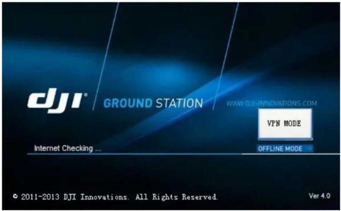
Start Window
(1) Start the Application of GS
● Network Detection, if the Network connection fails, it will go offline mode automatically.
- You also can go into offline mode by clicking the OFFLINE MODE button.
(2)Connect to Main Controller
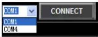
- Click Connect button on the upper right corner to connect to DJI autopilot main controller.
- If errors are showed, it means there may be some problem on connection, please check.
Application
Control Mode Switch
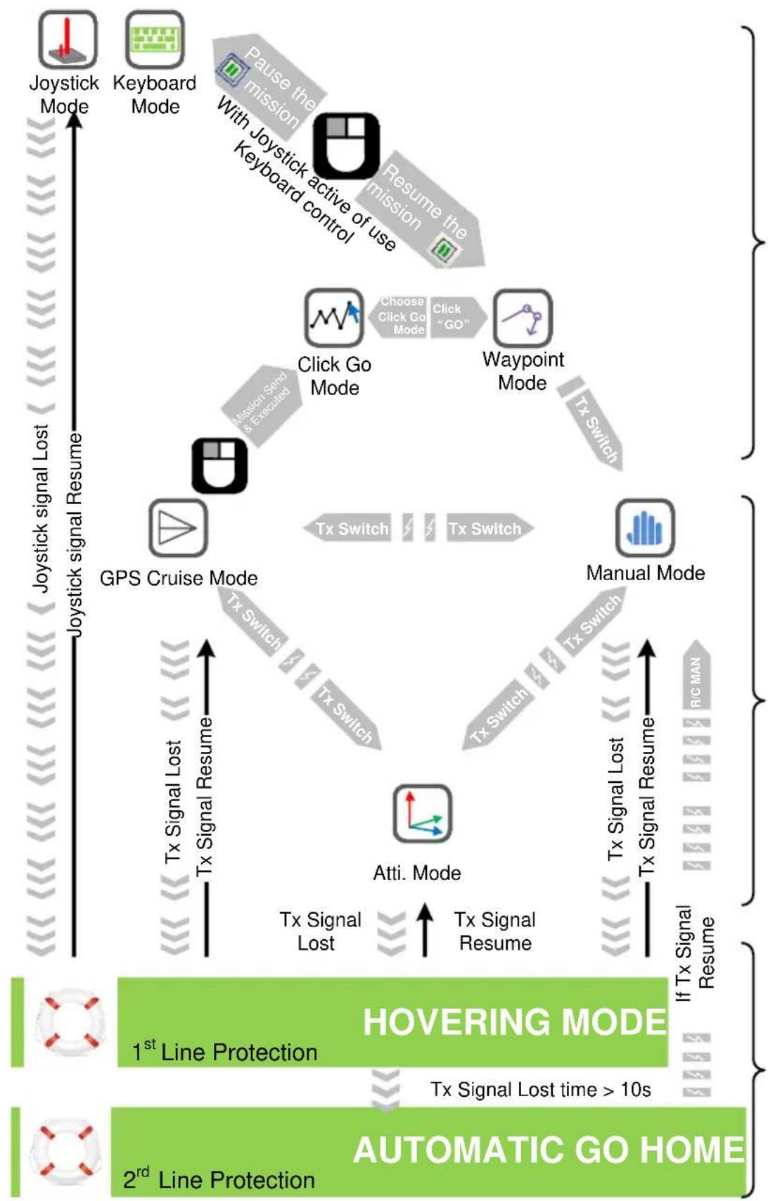
flowchart
graph TD
    A["Joystick Mode"] --> B["Keyboard Mode"]
    B --> C["Resume the mission"]
    C --> D["Choose Click Go Mode"]
    D --> E["Click "GO""]
    E --> F["Waypoint Mode"]
    F --> G["Tx Switch"]
    G --> H["Manual Mode"]
    H --> I["Tx Switch"]
    I --> J["Atti. Mode"]
    J --> K["Tx Signal Lost"]
    K --> L["1st Line Protection"]
    L --> M["Tx Signal Lost time > 10s"]
    M --> N["AUTOMATIC GO HOME"]

    subgraph Monitoring Path
        O["Go Mode"] --> P["Click Go Mode"]
        P --> Q["Choose Click Go Mode"]
        Q --> R["Click "GO""]
        R --> S["Waypoint Mode"]
        S --> T["Tx Switch"]
        T --> U["Manual Mode"]
        U --> V["Tx Switch"]
        V --> W["Atti. Mode"]
        W --> X["Tx Signal Lost"]
        X --> Y["Tx Signal Resume"]
        Y --> Z["Tx Signal Lost"]
        Z --> AA["Tx Signal Lost"]
        AA --> AB["RIC MAN"]
        AB --> AC["If Tx Signal Resume"]
    end

    subgraph Monitoring Path
        AD["GPS Cruise Mode"] --> AE["Tx Switch"]
        AE --> AF["Tx Switch"]
        AF --> AG["Tx Switch"]
        AG --> AH["Tx Switch"]
        AH --> AI["Tx Switch"]
        AI --> AJ["Manual Mode"]
        AJ --> AK["RIC MAN"]
        AK --> AL["If Tx Signal Resume"]
    end
GUI
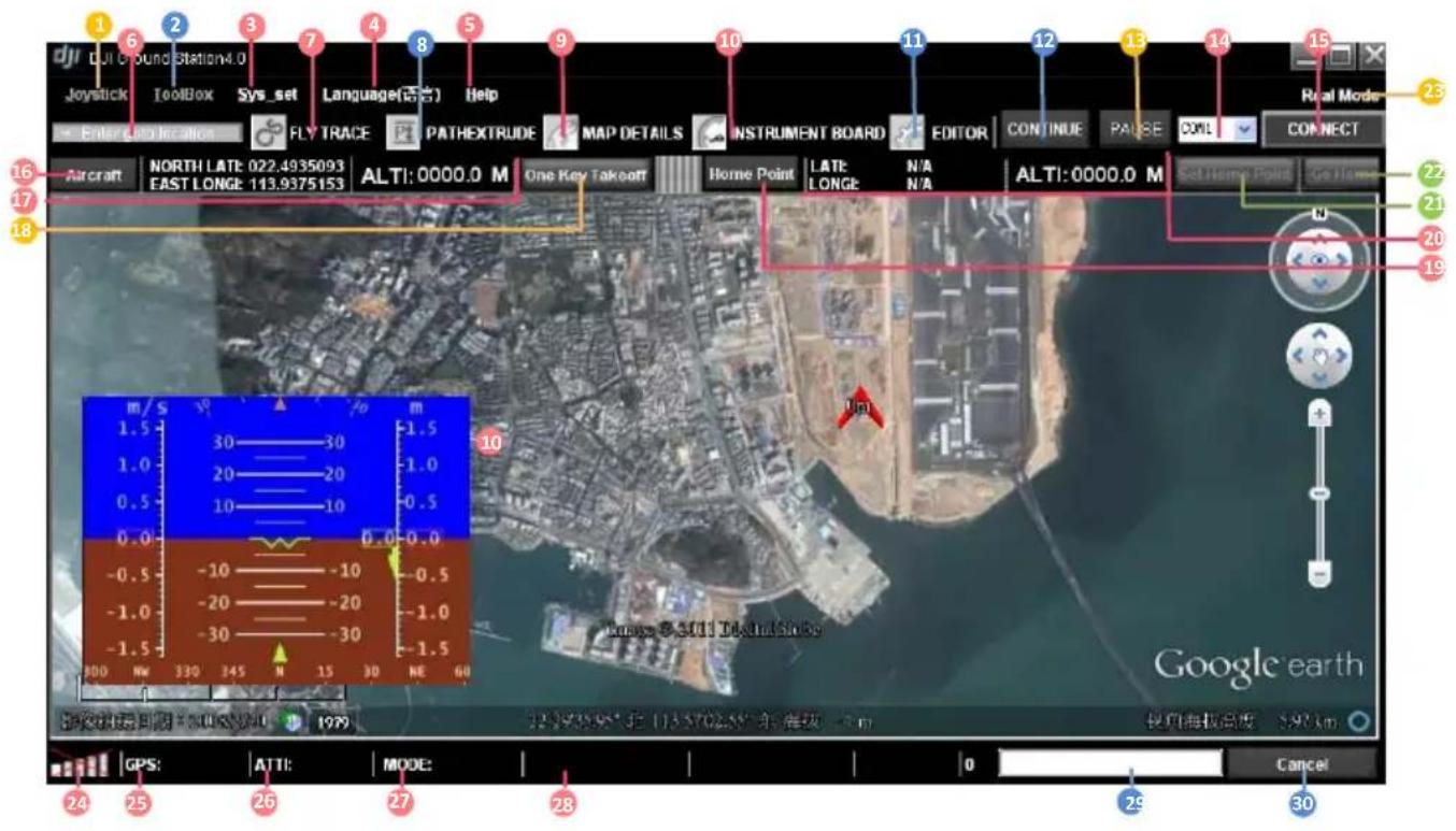
GUI Instruction
1. Joystick:
→ Stick: Choose your input equipment.
→ Choose Calibration: Joystick calibration.
→ Channel Mapping: Joystick channel mapping.
2. ToolBox:
→ Click Go Mode: A real-time single waypoint function.
→ F ChannelController: Customize F channels function of Main Controller.
→ Relative Coordinates Editor: Add a new waypoint relative to current waypoint.
→ Route Template: Route library.
→ Action Config: General purpose servo action configuration.
→ Photogrammetry Tool: Photogrammetry toolbox.
3. Sys\_set→Options:
→ Basic Setting:
● Sound: Turn on or off the sound.
- Instrument Board Style: Choose different style of the Instrument Board.
● Action Setting: Action number display interval.
● Pause Mode Control Interval: Frequency of data packages sent to MC.
- Target Line: Line between aircraft and current target.
→ Data Link Setting:
● The waypoint number of one package.
- Upload one package.
- Retry one package timeout.
→ NetWork Setting:
● GS VPN: VPN switch.
ON: If ON is selected, the VPN auto connect when you launch the GS.
OFF: If OFF is selected, the VPN not auto connect when you launch the GS.
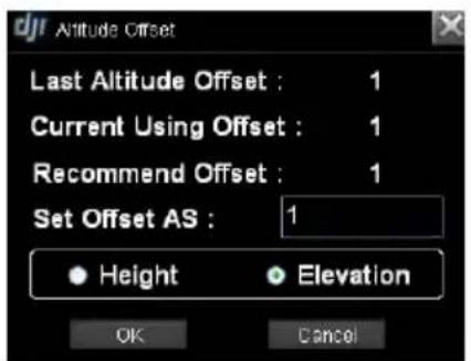
Sys_set→Altitude offset; Set up the altitude offset.
● Height: Height mode.
● Elevation: Elevation mode.
Sys_set→Data Record Folder: Include both Log and Mission Folders, for saving log files and flight route files.
- Language(语言): Click to change language, English or Chinese.
→ 中文.
→ English.
- Help:
→ Check for Update: Update software here.
→ About: Check your DJI Ground Station version here.
-
Enter location: Go to the location of your input.
-
Fly Trace: Click to show the trace of aircraft.
-
PathExtrude: Click if you want to see flight Path Extrude during mission editing.
-
Map Details: Click to see map details.
-
Instrument Board: Click if you want to display instrument board.
-
Editor: Click if you want to display mission editor.
-
Continue: If you switch into autopilot mode from waypoint mode, click Pause then click Continue, the aircraft will continue the remaining (Unfinished) mission.
-
Pause: Mission pause.
-
Serial port selection.
-
Connect: Click to connect to main controller.
-
Aircraft: Click to find aircraft location.
-
Real-time coordinates of aircraft, you can copy the data.
-
One Key Takeoff: Click to take off the aircraft.
-
Home Point: Find your home location.
-
Real-time coordinates of home location, you can copy the data.
-
Set Home Point: Change your home point.
- Go Home: Click to go home.
- To show Real mode or Simulation mode.
- Signal strength: Shows the connection state between controller and ground station.
- GPS: Real-time GPS signal quality.
- ATTI: Real-time attitude quality.
- MODE: Real-time control mode.
- Other state parameters: The flight control system decides.
→ WKM/A2/NAZA-M/NAZA-M V2/Phantom 2:
● MotorVoltage: Battery voltage.
→ ACE:
- ServoVoltage: Servo output voltage.
-
Pitch%: Real-time pitch percentage.
● Throttle%: Real-time throttle percentage. -
Download and upload progress bar.
-
Cancel: Cancel button.
1 View Mode
1.1 View Mode Procedures
- Check Signal Strength: shows no communication between GS and MC, please check Troubleshooting in Appendix. is constructed, can go to next step.
- Aircraft: When GPS signal is good enough, click Aircraft will show LATI, LONGI and ALTI of aircraft, then the aircraft logo will be showed on the map; if the aircraft logo can't be found, please double click Aircraft.
- AltitudeOffSet: Click AltitudeOffSet from Sys_set, you can just use the value recommended, and click OK. Read the paragraph below to get more details.
- Switch Height or Elevation Mode: Height mode shows relative height, and the 0 meter is the aircraft height when you choose Height mode, above 0 is positive and below 0 is negative. Elevation mode shows height above sea level, figure is showed in Fig②
- Home Point: Home point can be found only when GPS signal is good enough. If WKM/A2/NAZA-M/NAZA-M V2/Phantom 2, Home Point is 20 meters above the aircraft position where user pushes the throttle stick first time; while ACE is 30 meters.
- View Fly Trace, Instrument Board and State Information: For displaying flight track and aircraft state. Contents are decided by flight control system. Fig①A will be displayed if you are using ACE; Fig①B will be displayed if WKM/A2/NAZA-M/NAZA-M V2/Phantom 2. Instrument Board is showed in Fig③.

Fig①B WKM/A2/NAZA-M/NAZA-M V2/Phantom 2
Fig②
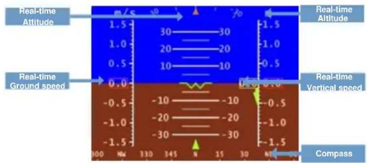
Fig③
1.2 System Setting
System Setting includes Options Setting, Altitude Offset Setting and Data Record Folder.
(1)Options
Tips:
Click DEFAULT to retrieve default parameters.
The Options setting includes both Basic Setting and Data Link Setting.
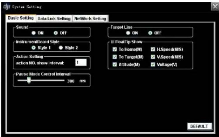
Basic Setting
● Sound: If switch on, there will be alarm sound when the radio signal is bad.
- Instrument Board Style: Choose different instrument board style.
- Action Setting: Set action number display mode. For example, 3 means that a mark will be displayed every three action intervals.
● Pause Mode Control Interval: Time interval of sending commands to the MC when use joystick or keyboard in pause mode, the smaller interval, the more fine control.
- Target Line: Display a line between aircraft and current target when switch on.
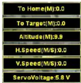
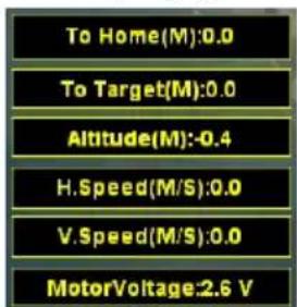
- UI Float Tips Show: If selected, the corresponding item(s) will real-time display in the main form. Voltage of ACE is Servo Voltage while WKM is Motor Voltage.
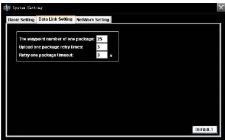
Data Link Setting
Setting parameters for the communication between MC and GS. Usually just keep DEFAULT parameters.
● The waypoint number of one package
- Upload one package retry times
- Retry one package timeout
UI Float Tips with ACE
UI Float Tips with WKM/A2/NAZA-M/NAZ
A-M V2/Phantom 2
(2) Altitude Offset Setting
GIS database (Google Earth™) is not precise, while Flight Path Mountain and other obstacle/building collision checking feature performed based on this database, which is not real-time or up-to-date. Google Earth™ plug-in is only for the purpose as a general landscape browser, for quick way points positioning without much safety guarantee.
- Pressure sensor is used for altitude sensing, leading the result varies according to weather. Therefore, you might have different altitude values on the same location at different times. However, its relative height may be far from precise than absolute altitude information in GIS.
● Due to above problems, the following method for relative flight height calculation would be most reliable.
1) Record the aircraft altitude before take-off, as L_Gound
2) Way point altitude = Relative Flight Height + L_Gound
Please keep in mind that this method is the most reliable way for flight path collision precaution.
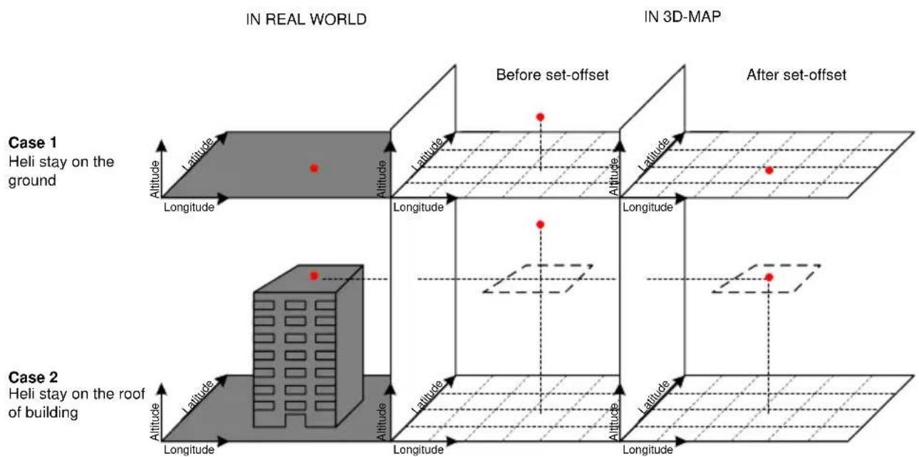
- The Altitude Offset value given is only for the purpose to avoid visual confusion, such as Case 1 in fig.① shown below. The aircraft represented by the red point was located on the ground in real world but floating in the sky within 3D-Map. You have to give a negative offset value to reduce the aircraft altitude for visual effect only. The calculate altitude offset function will give you a suggestion for offset setting but not guaranteed to be correct. Because if the aircraft is landed on the roof of the building as in Case 2 in figure shown below, and the building information will not appear in GIS database, which means you cannot use the same method as in Case 1. You should calculate this offset value with a known or estimated building height.
Tips:
We highly RECOMMEND you to consider the relative flight height discussed during flight mission editing.
(3) Data Record Folder
- Log Folder: Ground Station data recording function which is for recording all data transmitted and received by radio module. You can open the log files in this folder by notepad. You can send the log files to DJI customer service for analysis if you have any usage problems.
- Mission Folder: Auto saves each flight route. You can open these files by Editor.
2 Joystick/Keyboard Mode
Joystick/Keyboard mode is the 2^nd permission for users, and Fly Simulation, One Key Takeoff and Joystick/Keyboard functions can be operated.
2.1 Simulator
Pre-Flight Simulation aims to help you getting familiar with the Ground Station software. A successful flight under simulation mode does not guarantee your aircraft to work successfully in real world, since it is only a virtual environment based on the assumption that your aircraft is working under perfect condition with infinity power supply, favorable weather, and also that the GIS & GPS are providing 100% correct and precise information. The aircraft physical model in simulator might not perform the same flight characteristic as your real aircraft.
Notices:
ENSURE the following requirements whenever during/before Simulation Mode:
1) You MUST NOT take off your aircraft.
2) You MUST NOT turn on your aircraft engine/motor.
3) You CAN disconnect the power supply for electric motor, or disconnect the throttle control servo motor for fuel engine. Otherwise, incorrect operation could result in serious personal injuries.
Please follow the steps strictly for Simulation Mode use:
- Connect the whole main control system completely, including IMU、GPS, etc.
- Hold Ctrl then Right click, you will see simulate, and the aircraft logo will be at the current mouse position.
- Click simulate, you will see a "Warning" window.
- Click Yes to turn on Simulate Mode. Now GS is in Simulate Mode!!!
Notices:
- We HIGHLY RECOMMEND Simulation Mode for practicing purpose for flight mission edit, try to get familiar with all the operations of your Ground Station as much as you can.
- The simulation model requires a complete main control system connection, and you can reference to Assembly in DJI flight control system user manual.
2.2 One Key Takeoff
Notices:
One key takeoff is a function especially for WKM/A2/NAZA-M/NAZA-M V2/Phantom 2, that can be used only in autopilot mode and when GPS signal is good.
Messages may be showed as follows:
Successful takeoff message
"The aircraft is auto Takeoff!"
Error messages
"Auto Takeoff failure, GPS is not ready!"
"The aircraft is Takeoffing!"
"Auto Takeoff failure, the aircraft is already flying!"
"Auto Takeoff failure, please switch to auto mode!"
2.3 Joystick and Keyboard Mode
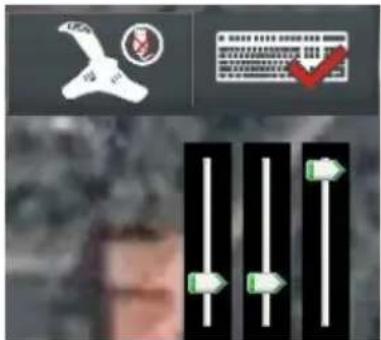
Please ensure GPS signal is good enough, the aircraft is already flying in air, and the control mode is autopilot mode; then click Pause, choose joystick or keyboard mode, Fig.① shows that keyboard is chosen, and then you can use keyboard control the aircraft, and drag the cursor to change roll, pitch and rudder control value, the higher the cursor, the bigger the control value.
Fig①
Keyboard Mode
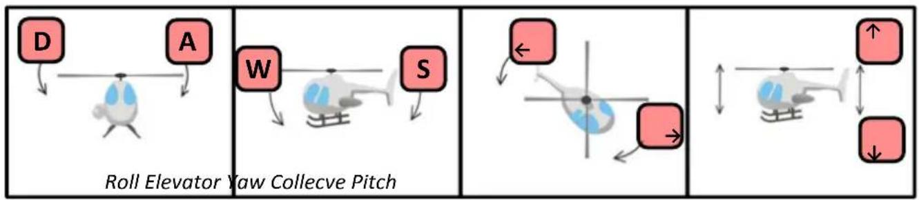
Use keys W, S, A, D, ↑, ↓ and ←, → to control the aircraft. A, D for Roll, W, S for Pitch, ←, → for Rudder and ↑, ↓ for Throttle. For example, use helicopter to be aircraft model, shown as Fig.②.
flowchart
graph TD
    A[" helicopter A"] --> B[" helicopter D"]
    C[" helicopter W"] --> D[" helicopter S"]
    E[" helicopter S"] --> F[" helicopter ↑"]
    G[" helicopter ↑"] --> H[" helicopter ↓"]
Fig②
Joystick Mode
→ Requirement
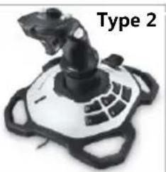
Joystick control based on a third party hardware controller, you can choose your preferred device based on the two types of joystick indicated below (Fig③).
Type 1: Traditional R/C style flight simulation controller; or your R/C Tx with a third party simulator link.
Type 2: Linear single stick 3D controller.
natural_image
Exterior view of a black industrial control device with dual motors and a red warning label (no readable text or symbols)Real Flight® interLink™ Plus Controller
natural_image
Top view of a black robotic device labeled 'Type 2' (no other text or symbols visible)Logitech® Extreme™ 3D Pro Joysck
Fig③
→ Technology Requirements
- At least 4 linear control channels are necessary; otherwise the joystick function will not work properly.
- Use USB connection.
→ Connection
Joystick→Choose Joystick
Refer to the user manual of the specific controller / Joystick you choose, and ensure the USB cable is properly connected.
Notices:
Please ENSURE the Joystick is properly connected physically, do not disconnect the joystick connection when Joystick Mode is activated.
→ Calibration
Joystick→Calibration
| Steps | Joystick (Type1) | Type1 | Type2 |
| Step 1 | 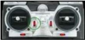 | Place all trim levers (for physical fine turning) in their neutral, or centered position. Click Next. | For Type 2 controller, might not have these physical fine turning levers. Click Next. |
| Step 2 | 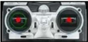 | Center all the sticks. Click Next to continue. | Center all stick including throttle stick. Click Next to continue. |
| Step 3 | 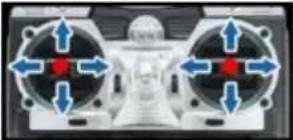 | Move all sticks through their motion range completely several times. When completed, click Finish. | Move the sticks through their 3D motion range completely several times, including pitch. When completed, click Finish. |
→ Channel Mapping
Joystick→Channel Mapping
- Each control channel can be reversed, and mapped to one of the control functions listed in corresponding drop down boxes.(Fig①)
- These control function are 'Roll', 'Elevator', 'Yaw' & 'Collective Pitch', they represent the cyclic and rudder control of your aircraft. use helicopter for example, shown in the figures below(Fig②). Where the '+' represents positive channel value, '-' represents negative channel value.
- Push your joystick, and the channel value feedback will tell whether it matches with suggested joystick control direction or your own settings, and then make your adjustments. For Type 1 controller, please refer to the controller's manual.
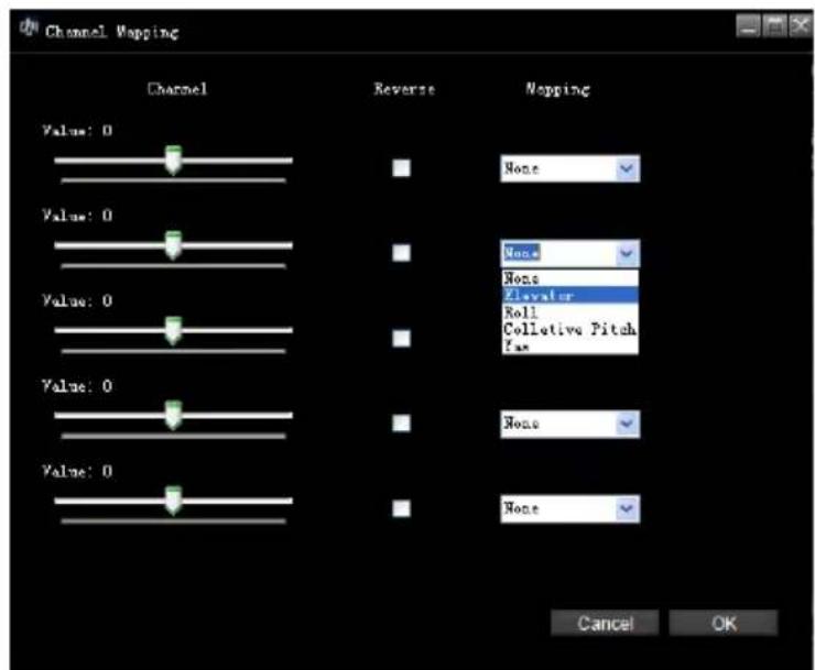
Fig①
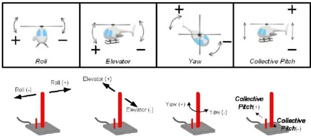
Fig②
3 Click Go Mode
Click Go Mode is a real-time single waypoint flight mode. Under this mode, you can send a waypoint to your aircraft immediately.
- Please ensure GPS signal is good enough, the aircraft is already flying in air, and the control mode is Autopilot Mode (ACE is GPS Atti. or GPS Cruise Mode, WKM/A2/NAZA-M/NAZA-M V2 is GPS Atti. Mode, Phantom 2 is Ready to fly or Ready to fly (non-GPS)).
- ClickToolBox→Click Go Mode to open the window as the figure shows.
- Click Enter Click Go Mode. Now the aircraft will go into hovering station.
- Input the waypoint Altitude and aircraft Speed.
- Hold the Space key on the keyboard, move the mouse in the 3D map, left click to set the waypoint. Then the aircraft will fly toward this waypoint immediately. You can also set a new waypoint during the flight.
- Click Exit Click Go Mode, the aircraft will hover again.
- Click CONTINUE button to continue the previous flight.
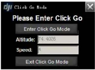
Notices:
- The aircraft will go into hovering station while the MC isn't receive a heartbeat package from the GS in 5 seconds;
- The aircraft will go into auto go home while the MC isn't receive a heartbeat package from the GS in a minute.
Tips:
When in the Click Go Mode, all Tx control sticks are disabled. To regain control using the Tx, flip the mode switch to Manual mode, and then to other control modes (ACE: Atti, GPS Atti, or GPS Cruise mode;
WKM/A2/NAZA-M/NAZA-M V2: Atti, GPS Att; Phantom 2: Ready to fly, Ready to fly (non-GPS).
4 Waypoint(Single Waypoint User Skip This)
Waypoint package includes Waypoint Mode, Auto Takeoffing/Landing, F Channel Controller, General Purpose Servo Action, 6 Pre-Programmed Route Templates and Photogrammetry Tool.
4.1 Waypoint Mode
See the flow chart to get the information about Waypoint mode operation.
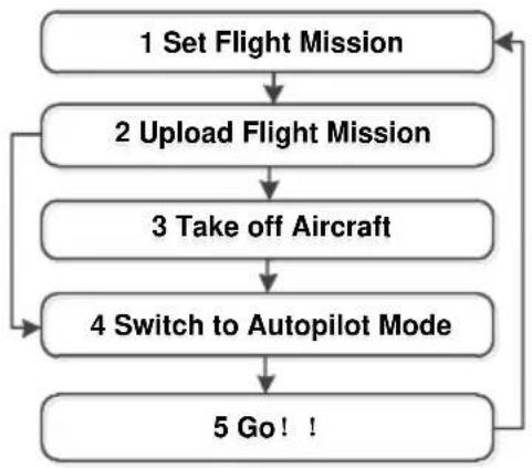
flowchart
graph TD
    A["1 Set Flight Mission"] --> B["2 Upload Flight Mission"]
    B --> C["3 Take off Aircraft"]
    C --> D["4 Switch to Autopilot Mode"]
    D --> E["5 Go! !"]
    E --> A
Mission Editor
Instructions
1) LOG to print info. Such as: upload success, upload failed...
2) Waypoint list: You can click icon + before Editing Mission to show all waypoints in the table.
3) You will see Mission properties if 14) selected.
→ Mission properties
- MissionTimeLmt: If the flight-time exceeds the value (>=60sec), it will go home automatically.
- Route: The mission execution mode selection: includes both modes of Start_to_End and Continuous.
- StartWayPoint: Define the first way point that the aircraft goes to after clicking GO. Select the proper way point index number listed.
● VerticalSpeedLimit: Vertical speed for up or down direction, unit is m/s.
→ Set Mission properties
- SetAllWPsAlt: Set altitude of all waypoints.
- SetAllWPSSpeed: Set speed of all waypoints.
- SetAllWPsTurnMode: Set turn mode of all waypoints: StopAndTurn, Bank_turn, Adaptive_Bank_Turn and None.
- SetAllAction: Setup the parameters of a set of repeat actions.
4) Description of selected item.
5) Altitude change 10m or 1m per click.
6) Add new way point by click+, and then left click on the map. Or left click on the map with Ctrl. Click to delete the selected points.
7) Clear: Click the Clear button to delete running mission or editing mission on the map.
8) Save and Open the mission.
9) Cancel all edited waypoints.
10) Upload the mission to Main Controller.
11) Click Go to execute assigned mission, including Auto Take off as assigned.
12) Show Waypoint properties. Any item in Editing Mission selected is writeable; Assigned Mission is read only.
→ Latitude & Longitude: Units are in degree.
→ Altitude: Unit is in meters.
→ TurnMode: Set the turn mode individually.
→ Forward Flight Speed: Velocity from previous point to current point is limited to <= 25 m/s.
→ HeadingDegree: Heading degree facing this way point, unit in degree.
→ HoldTime: The time to stay at this waypoint, unit in second.
13) Waypoint Action properties
→ Period: (Unit: second) Setting the time period of the action.
→ RepeatTime: Setting the repeat time of the action assigned.
→ StartDelay: (Unit: second) Setting when to activate assigned servo actions if the flight arrives this way point.
→ RepeatDistance: (Unit: meter.)Setting the repeat action in distance.
15) Set the editor box transparent.
16) Set the editor box size.
(I) Flight Mission Setting
STEP1: Click to open the mission editor, see fig.①.
STEP2: Click New to edit a new mission.
STEP3: Add waypoints.
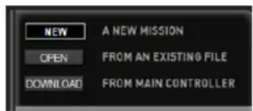
Fig①
→ Add waypoints
There are two ways on adding waypoints. A maximum of 200 waypoints can be added in the ACE waypoint mode, a maximum of 50 waypoints can be added in the WKM/A2 waypoint mode, and a maximum of 16 waypoints can be added in the NAZA-M/NAZA-M V2/Phantom 2 waypoint mode. If selected, the waypoint will change to be green, see fig.②.
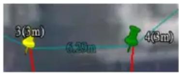
Fig②
(1) Add Point by Point
STEP1: Click +, or press Ctrl。
STEP2: Left click on the 3D-Map where the locations you want to add a way point.
Tips:
Repeat above procedure if you wish to add more new waypoints. The initial waypoint index will be 0, incremented by 1 each new way point is added. If you want to insert a point before another point, you can move the mouse over the point then press Ctrl with Left click.
(2) Using Relative Coordinates Editor
After the first waypoint, you can use Toolbox -> Relative Coordinates Editor to add new points.
-
Select one waypoint, then press Shift+P you will see the input window shown as fig.③.
-
Use Tab to switch between these two input frames.
-
Input the relative coordinates: Angle is the relative angle to the north of current waypoint; Distance is the relative distance to the
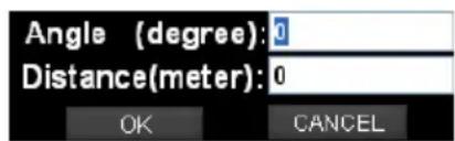
current waypoint.
Fig③
- Press Enter, then you will see a new waypoint after the current waypoint.
→ Delete Way Points
-
Select waypoint either in map or in Editing Mission Menu, and the selected waypoint is in green;
-
Click - or press delete to delete all the waypoints added.
Tips:
Repeat above procedure to delete more. Click CANCE to delete all the way points added.
→ Waypoint Properties Editing
Select the way point in 3D-Map or in the Editing Mission Menu. See figure as following, Altitude, TurnMode, Forward Flight Speed, HeadDegree and HoldTime can be set, then press Enter to confirm.
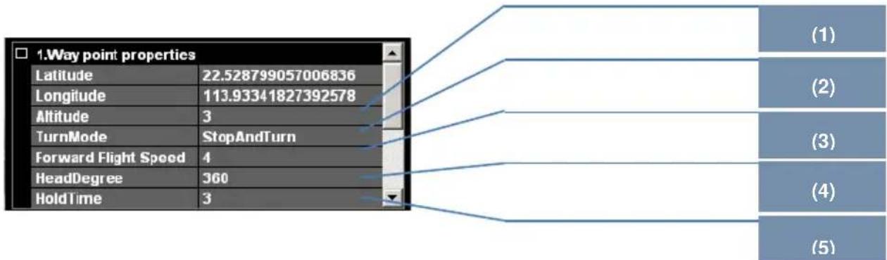
(1) Altitude
The altitude (unit m), if pointed to height mode, means relative height; otherwise altitude mode means the waypoint altitude.
- Edit the altitude of each waypoint by clicking the +1 +10 -1 -10
● Type in the precise altitude in the box.
(2) TurnMode
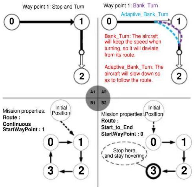
There are three different turn modes for the aircraft at each waypoint: StopAndTurn, Bank_Turn and Adaptive_Bank_Turn. The default turn mode in the system is StopAndTurn. Change it according to the following steps. The Hold Time in waypoint property is deactivated if Bank_Turn or Adaptive_Bank_Turn is chosen.
- Make a selection from the drop down box after TurnMode for mission execution mode.
(3) Forward Flight Speed
This Speed is the air speed of aircraft flying to specific way point editing. (Unit in m/s). In Waypoint Mode, the default speed is 4m/s, and the maximum speed allowed is 25m/s.
- Type in the precise Forward Flight Speed in the box.
(4) HeadDegree
When the aircraft arrives at a given point where to head towards a certain direction, you can use this value. (Unit in degree).
- Input the degree value in the item.
- Right click waypoint and hold on, then move wheel or press↑, ↓ to change head degree.
(5) HoldTime
Sets the time to stay in a particular waypoint, not for Bank_turn, only for StopAndTurn (In second).
- Type in the time to stay in a waypoint after the TimeHold in the box.
→ Mission Properties Editing
Click Editing Mission and the Mission properties figure shown as following. Please set MissionTimeLmt, Route selection, StartWayPoint, erticalSpeedLimit and Set Mission properties, and press Enter to confirm.
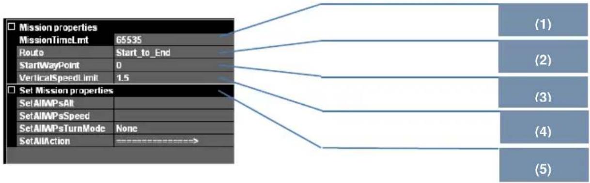
flowchart
graph TD
    A["Mission properties"] --> B["MissionTimeLmt 65535"]
    A --> C["Route Start_to_End"]
    A --> D["StartWayPoint 0"]
    A --> E["VerticalSpeedLimit 1.5"]
    F["Set Mission properties"] --> G["SetAIMPSAll"]
    F --> H["SetAIMPSSpeed"]
    F --> I["SetAIMPSTurnMode None"]
    F --> J["SetAllAction ==========="]
    G --> K["(1)"]
    H --> L["(2)"]
    I --> M["(3)"]
    J --> N["(4)"]
    K --> O["(5)"]
(1) MissionTimeLmt
If the aircraft's flying time exceeds the value, it will go home automatically. (Default value is 65535sec. Min value is 60sec, Max value is 65535sec.)
- Type in precise time in the box after MissionTimeLmt.
(2) Route
Selection route modes: Start_to_End or Continuous Start_to_End: execute once from start point to end point; Continuous: repeat from start point to end point. (Default setting is Start_to_End.)
- Make a selection from the drop down box after Route for mission execution mode.
(3) StartWayPoint
Setting for start waypoint from the existing waypoint indexes. (Default start waypoint is 0.)
- Make a selection from the drop down box after StartWayPoint from the existing way point indexes.
(4) VerticalSpeedLimitSetting
This Speed limit is the absolute velocity of aircraft in vertical direction, up or down (Unit in m/s). The default vertical speed limit is 1.5m/s and the maximum speed allowed is 5.0m/s.
- Type in the precise speed in the box after VerticalSpeedLimit.
(5) Set Mission properties
- SetAllWPsAlt
- SetAllWPsSpeed
- SetAllWPsTurnMode
- SetAllAction
The properties setting above, once set, then all the destinations will change and be the same; if a single waypoint's properties are set individually, then the corresponding waypoint properties will change.
◆ Examples for Way Point turning mode: Shown as figure A1/A2 as following.
Examples for Mission/Way Point properties setting: B1/B2 Selection for the state of Route, and StartWayPoint.
flowchart
graph TD
    A["0"] --> B["1"]
    B --> C["2"]
    C --> D["3"]
    D --> E["1"]
    E --> F["2"]
    F --> G["3"]
    G --> H["1"]
    H --> I["2"]
    I --> J["3"]
    J --> K["1"]
    K --> L["2"]
    L --> M["3"]
    M --> N["1"]
    N --> O["2"]
    O --> P["3"]
    P --> Q["1"]
    Q --> R["2"]
    R --> S["3"]
    S --> T["1"]
    T --> U["2"]
    U --> V["3"]
    V --> W["1"]
    W --> X["2"]
    X --> Y["3"]
    Y --> Z["1"]
    Z --> AA["2"]
    AA --> AB["3"]
    AB --> AC["1"]
    AC --> AD["2"]
    AD --> AE["3"]
    AE --> AF["1"]
    AF --> AG["2"]
    AG --> AH["3"]
    AH --> AI["1"]
    AI --> AJ["2"]
    AJ --> AK["3"]
    AK --> AL["1"]
    AL --> AM["2"]
    AM --> AN["3"]
    AN --> AO["1"]
    AO --> AP["2"]
    AP --> AQ["3"]
    AQ --> AR["1"]
    AR --> AS["2"]
    AS --> AT["3"]
    AT --> AU["1"]
    AU --> AV["2"]
    AV --> AW["3"]
    AW --> AX["1"]
    AX --> AY["2"]
    AY --> AZ["3"]
    AZ --> BA["1"]
    BA --> BB["2"]
    BB --> BC["3"]
    BC --> BD["1"]
    BD --> BE["2"]
    BE --> BF["3"]
    BF --> BG["1"]
    BG --> BH["2"]
    BH --> BI["3"]
    BI --> BJ["1"]
    BJ --> BK["2"]
    BK --> BL["3"]
    BL --> BM["1"]
    BM --> BN["2"]
    BN --> BO["3"]
    BO --> BP["1"]
    BP --> BQ["2"]
    BQ --> BR["3"]
    BR --> BS["1"]
    BS --> BT["2"]
    BT --> BU["3"]
    BU --> BV["1"]
    BV --> BW["2"]
    BW --> BX["3"]
    BX --> BY["1"]
    BY --> BZ["2"]
    BZ --> CA["3"]
    CA --> CB["1"]
    CB --> CC["2"]
    CC --> CD["3"]
    CD --> CE["1"]
    CE --> CF["2"]
    CF --> CG["3"]
    CG --> CH["1"]
    CH --> CI["2"]
    CI --> CJ["3"]
    CJ --> CK["1"]
    CK --> CR["2"]
    CR --> CS["3"]
    CS --> CT["1"]
    CT --> CU["2"]
    CU --> CV["3"]
    CV --> CW["1"]
◆ Examples for path of way point:
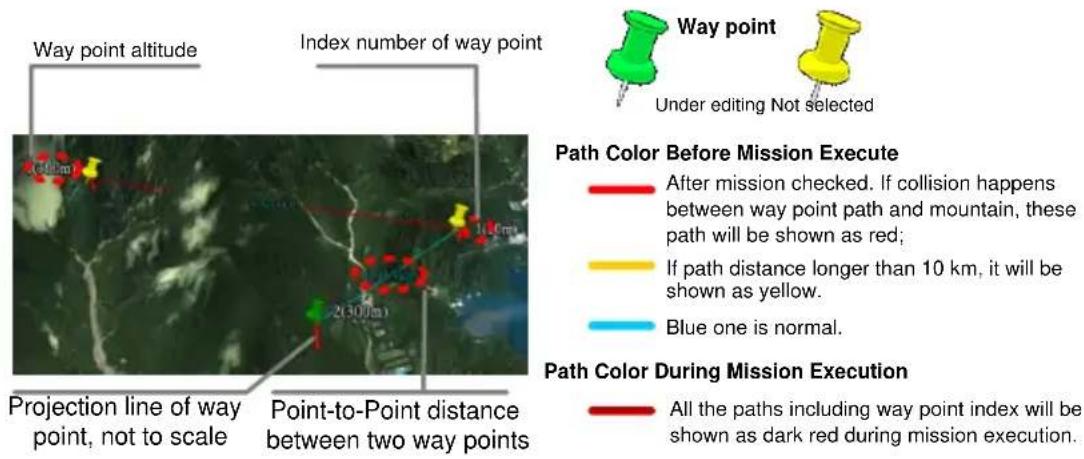
→ Mission Save & Load
Mission Save
- Click SAVE to save mission edited.
- Choose a name with extension '.awm'. For Example: DJI_Mission_20100101.awm.
- Mission Load
- Click OPEN to load mission saved; choose mission file with extension '.awm'.
Notices:
The Altitude offset value will not be saved in mission file. Please set it every time!!!
(II) Upload Flight Mission
Final Check & Mission Transmitting: Click UPLOAD on the upper bottom of the mission Editor to send flight mission to DJI autopilot main controller. Here a mission review table as following example will appear for mission final check. Press OK. The mission is ready to be executed after synchronized successfully.
Example of "Mission Review" table under 3 waypoints mission
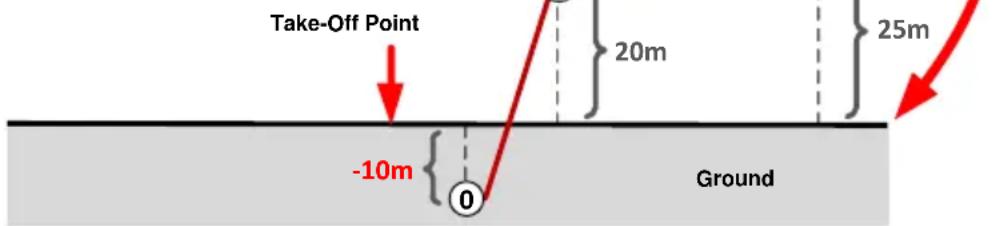
| Waypoint | Latitude | Longitude | Altitude | Speed | Turn Mode | Altidiff | Action Module |
| 0 | xxxxx | xxxxx | xxxxx | 4 | StopAndTurn | -10 | NULL |
| 1 | xxxxx | xxxxx | xxxxx | 6 | StopAndTurn | 20 | In meter |
| 2 | xxxxx | xxxxx | xxxxx | 15 | StopAndTurn | 25 | In second |
Number [Altidiff] is the current relative height from waypoint(s) to aircraft. Number [Take Off Point] is the relative height from waypoint(s) to take-off location.
Example shows a possible error at waypoint 0 altidiff -10 m in RED. Because the waypoint is 10 meters below ground.
Tips:
After synchronization, if mission is re-edited, you should re-do the synchronization.
(III) Take off Aircraft
After finishing all the above steps, take off the aircraft in one of three takeoff modes. If you want to use Auto Takeoff and Landing function, please skip the step III and go to Step IV directly. You can take off your aircraft in Manual Mode please hover it at a suitable height.
(IV) Switch to Autopilot Mode
Switch to any autopilot mode on your TX. Ground station is able to control the aircraft only after switching to autopilot mode!
Notices:
Making sure sufficient GPS satellite signal is acquired.
Tips:
Refer to DJI Flight control system User Manual for Manua, Atti, GPS Atti, GPS Cruise switching of your flight control system, and also the Manual of your R/C Transmitter (Tx).
(V) GO!!
Click Go in the mission Editor and the aircraft will fly automatically according to the path set in the flight mission.
Tips:
- Using EDIT to re-edit the mission, while a mission is in process. Please click EDIT in mission Editor to do so. Then the mission editor will return to the state explained in previous section Flight Mission Setting
- Using PAUSE to pause the mission, while a mission is in process. Please click PAUSE, and the aircraft will slow down and stay hovering. Click CONTINUE and the aircraft will resume the un-finished mission.
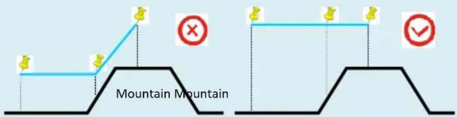
When you set the waypoints for the aircraft to climb a mountain, please make sure that you leave enough distance between the aircraft and the mountain, in order to avoid collision caused by aircraft air speed.
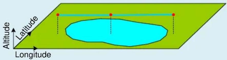
Please note that when you set a waypoint above water such as lake/sea/river, the default altitude the map shows will be at the bottom of the water body. Please be careful in setting altitude over water.
4.2 Auto Takeoff and Landing
Please read this carefully in order to work properly. It is imperative that you understand the procedures outlined before executing auto takeoff and landing functions.
Tips:
ACE users need to obtain Semi Auto Takeoff and Landing permission. WKM/A2/NAZA-M/NAZA-M V2/ Phantom 2 has this function built-in.
Auto Takeoff
Only after assigning or editing all waypoints, the mission is ready to take off.
- Place transmitter throttle stick to the lowest position. Otherwise, a tip The aircraft is on the ground, but the throttle is not in the lowest position, please do not switch to manual mode! will be shown.
- Flip the flight mode switch to either GPS-Cruise or GPS-Atti mode.
- Press Go command on the Editor, the aircraft main rotor will begin to spool up.
Notices:
Aircraft is ascending to waypoint altitude, please place throttle to mid-stick! This warning will go away after you place the throttle stick at mid-point, a safety feature in case you accidentally bump the mode switch to Manual mode or GPS Atti mode.
Auto Landing
After mission completing or the aircraft returning home, and the aircraft
hovers within visual contact. Use Ground Station keyboard for auto
EDIT
DOWNLOAD
Auto landing
landing (Press pause button then select keyboard control). Auto Landing button will be available. Use W/S □ (Pitch), A/D (Roll), ↑/↓ (Throttle) and ←/→ (Rudder) to navigate to decent landing zone, or allowing Ground Station automatically provided a landing zone is clear of any obstacles, in order to decent the aircraft.
Use one of the methods bellow to land the aircraft.
(1) Click Auto landing, aircraft will auto land then stop engine by itself. In the latter situation, to terminate auto landing, please press ↑ or ↓, or deselect the keyboard control button →
(2) Use ↓ to land the aircraft. After landing, keep holding ↓ until engine stops.
Notices:
Please press pause button and select keyboard mode, before auto landing operation.
4.3 F Channel Controller
Use Ground Station to customize the MC's F channel control, so that you can control the external payloads such as camera and gimbal.
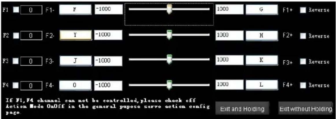
- ClickToolBox F_ChannelControl, he setup window shows as the follow figure.
- Click the small box beside channel name to choose the channels will be used.
- Click the button with letter, then press key shown and you need to choose a new control key on the keyboard.
- Setup the channel measuring range in the number boxes.
- Usually, the slide left endpoint represents the minimum value. However you can tick the Reverse box to reverse the measuring range.
- Click Exit and Holding to exit and keep the range value; Click Exit without Holding to exit and forget the range value.
Tips:
ACE/A2 supports F1, F2, F3 and F4;
WKM /NAZA-M/NAZA-M V2 supports F1 and F2 only.
For A2, set the F channels function through the following four methods:
| “Advanced” of A2 Assistant | “RC” of A2 Assistant | “F_ChannelController” of Ground Station | “GP Servo Action Config” of Ground Station | |
| F1 | Landing gear (mapping required) | Mapping | Click to enable | N.A. |
| F2 | Servo and gimbal | Mapping | Click to enable | Click to enable |
| F3 | Mapping | Click to enable | N.A. | |
| F4 | Parachute | Mapping | Click to enable | N.A. |
When you set the F channels function through methods above, the priority of F1\~F4 output channels function is as follows:
"Advanced" of A2 Assistant > "RC" of A2 Assistant > "F_ChannelController" of Ground Station > "GP
Servo Action Config" of Ground Station.
Using the F1 channel for example: If you enable "Advanced" in the A2 Assistant and F1 in
"F_ChannelController" of the Ground Station at the same time, the landing gear function for F1 output channel has the higher priority.
4.4 General Purpose Servo Action (GP-Servo Action)
GP-Servo Action is supported by one of the servo output channels in the transmitter, which will work as an interface between DJI flight control system and external devices. This feature allows DJI autopilot to operate your external devices automatically during basic aircraft waypoint mission.
GP-Servo Action Setting
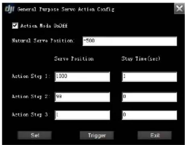
- ClickToolBox GP Servo Action Config to open the General Purpose Servo Action Config windows;
- Click the box Action Mode OnOff to enable the GP-Servo Action function;
- For ACE, the GP-Servo uses the output channel F4 in the MC; for A2, the GP-Servo uses the output channel F2 in the MC; for WKM/NAZA-M/NAZA-M V2, the GP-Servo uses the output channel F1 in the MC.
Notices:
The servo position value is from -1000 to 1000; the Stay Time is in second.
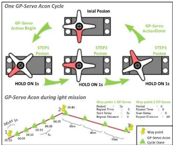
The software aims to let you program four different servo positions, use servo for example.
- Initial servo position and three specific servo working positions.
● Timing of each servo transition in one GP-Servo Action cycle.
● The repeat time of a GP-Servo Action assignment on a particular assigned way point.
● Time gap between each GP-Servo Action assignments.
Please assign a default position for servo in natural status, and others 3 positions as well as the time to stay in such positions for servo to work as assigned. After all settings (click Set to save the settings), then click Trigger you review the GP-Servo Action, as we explained in One GP-Servo Action Cycle.
flowchart
graph TD
    A["Initial Posion"] --> B["STEP1 Posion"]
    B --> C["STEP2 Posion"]
    C --> D["STEP3 Posion"]
    D --> E["One GP-Servo Acon Cycle"]

    subgraph Cycle 1
        F["GP-Servo Action Begin"] --> G["HOLD ON 1s"]
        G --> H["STEP1 Posion"]
        H --> I["HOLD ON 1s"]
        I --> J["STEP2 Posion"]
        J --> K["HOLD ON 1s"]
    end

    subgraph Cycle 2
        L["GP-Servo Action Done"] --> M["HOLD ON 1s"]
        M --> N["STEP3 Posion"]
        N --> O["HOLD ON 1s"]
    end

    subgraph Cycle 3
        P["GP-Servo Acon During Light Mission"]
    end

    style Cycle 1 fill:#f9f,stroke:#333
    style Cycle 2 fill:#bbf,stroke:#333
    style Cycle 3 fill:#dfd,stroke:#333
Tips:
For A2, set F channels function through the following four methods:
| “Advanced” of A2 Assistant | “RC” of A2 Assistant | “F_ChannelController” of Ground Station | “GP Servo Action Config” of Ground Station | |
| F1 | Landing gear (mapping required) | Mapping | Click to enable | N.A. |
| F2 | Servo and gimbal | Mapping | Click to enable | Click to enable |
| F3 | Mapping | Click to enable | N.A. | |
| F4 | Parachute | Mapping | Click to enable | N.A. |
When you set the F channels function through methods above, the priority of F1\~F4 output channels function is as follows:
"Advanced" of A2 Assistant > "RC" of A2 Assistant > "F_ChannelController" of Ground Station > "GP Servo Action Config" of Ground Station.
Using the F2 channel for example: If you enable "RC" in the A2 Assistant and F2 in "GP Servo Action Config" of the Ground Station at the same time, the mapped function for F2 output channel has the higher priority.
Way point Action Editing
Find and set the waypoint action properties according to the following procedures:
- Click, the Mission Status will show Editing Mission label upon the Mission Editor.
- Edit flight mission.
- Select the waypoint either in 3D-Map or in the EditingMission menu, and get Waypoint action, shown as Fig.
- Give the proper parameters explained in Editor: Period, RepeatTime, StartDelay, and RepeatDistance. Set RepeatTime and RepeatDistance zero to disable the GP-Servo Action.
Tips:
Use SetAllActioninMission properties to setup the sequence interval. For example: 0 means action property is applied to no waypoint; 1 means action property is applied to every waypoint; 2 means action property is applied to every two waypoints; 3 means action property is applied to every three waypoints, etc.
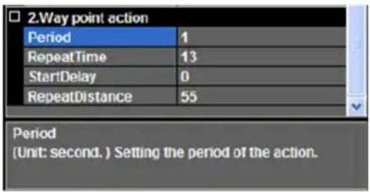
Fig. ①
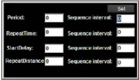
Fig. ②
4.5 Six Pre-Programmed Route Templates
Use one of the six Route templates to generate points automatically.
- Open the Template Form Toolbox → Route Template, shown as Fig.①.
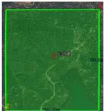
- Click Add Area button to add an area, shown as Fig.②.
- Choose the waypoint icon of the chosen area, and drag it to change the area size.
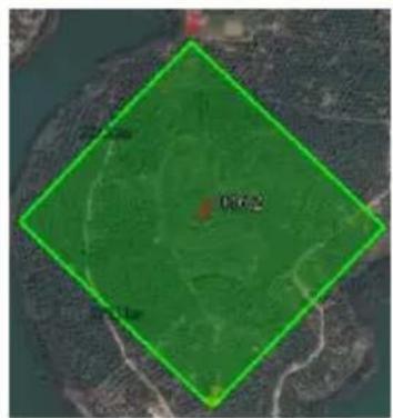
- Left click mouse to rotate the area, rotation 30° per click; click to adjust the area rotation angle and rotation 0.1° per click, as Fig. ③ shown.
- Click one Template to generate waypoint(s), for example, choose Scan, as Fig. ④ shown.
- Click Import to Edit List to do template edit, for example, choose Scan, as Fig. ④ shown.
Tips:
● You can exchange and redo STEP3 and STEP4, until get an area needed.
- Dragging the waypoint icon also can move the area, and the chosen icon shows green.
- More than one area can be added; operation will effect on every chosen area, if more than one area is chosen.
● Left click mouse to choose or not choose an area, green area is chosen, and red is not.
- You need to choose the area if you want to delete it by click Delete Area.
- Click Scan button once or twice, the route waypoints will be assigned vertically or horizontally
- Mouse on Param shows parameter meaning, row numbers for Scan and points for others.
- You can set sea level at Alti, and ensure that the altitude is higher than the aircraft altitude.
- Edit waypoints after clicking Import to Edit List button
- 5 Waypoints station will not enable Scan mode.
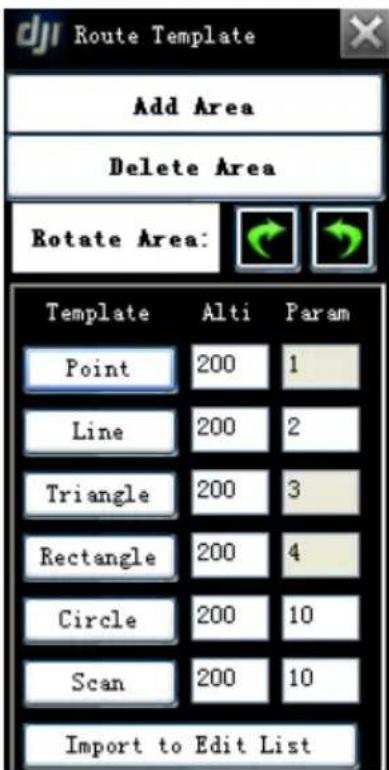
Fig.③
natural_image
Aerial or satellite view of a green landscape with visible roads, waterways, and a marked point '2000' (no text or symbols beyond the label)Fig.②
natural_image
Aerial view of a green diamond-shaped agricultural or agricultural area with no visible text, numbers, or symbols.Fig.③
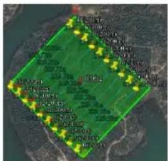
Fig.④

Fig.⑤
4.6 Photogrammetry Tool
Photogrammetry tool is for creating the professional maps by aerial photography easily. In order to do that, you need to setup the servo action and mission path correctly as follows.
Tips:
This tool is actually a functions combination. It simplifies the parameters setup procedure for the aerial photography.
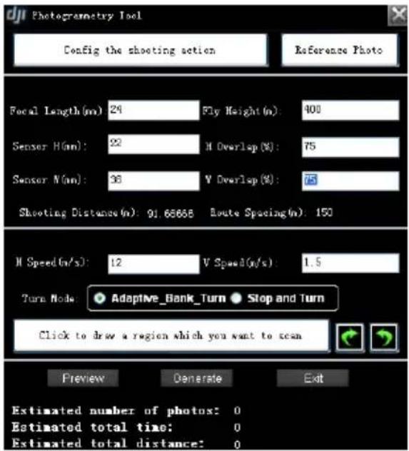
Fig.①
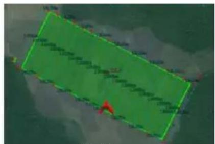
Fig.②
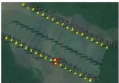
Fig.③
- ClickToolBox→Photogrammetry Tool to open the setting window, shown as Fig.①.
- Click Config the shooting action to setup the servo action for the camera shooting action, reference to section 4.4.
- Click Reference Photo to see if the camera is working as you want.
- Fill in the right Focal Length, Sensor Height, and Sensor Width according to the camera.
- Fill in the Fly Height, H Overlap and W Overlap as you like. H Overlap and W Overlap represent the overlap percentage across the sensor height and width.
- Fill in the flight horizontal and vertical speed in H Speed and V Speed separately.
- Choose turn mode between Adaptive_Bank_Turn and Stop and Turn.
- Click Click to draw a region which you want to scan to choose an area, reference to section 4.5 to change the area.
- Click Preview to preview the mission plan, shown as Fig.②.
- If everything is OK, click Generate to generate all waypoints. Now you will have a flight mission generated automatically in the Editor, shown as Fig. ③.
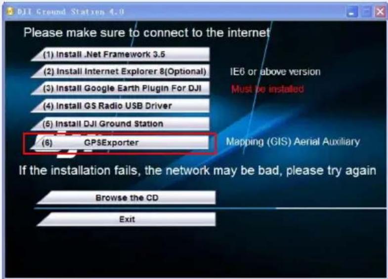
- Use the GPSEplorer to export the attitude data when the aircraft take a photograph. Please download this tool from our CD, or from DJI official website.
Tips:
You can edit any waypoint in the Editor after generate all waypoints.
Appendix
List of Ground Station Shortcut Keys
| Operation | Function |
| View Mode | |
 Left Key+ Left Key+ | Up/Down/Left/Right to move the map |
| ↑, ↓, ←, → | Up/Down/Left/Right to move the map |
 Left Key+ Left Key+ | Up/Down/Left/Right to rotate the map |
| Ctrl+Mouse Roll Up Ctrl+Mouse Roll Down | Left/Right to rotate the map |
| Shift+Mouse Roll Up Shift+Mouse Roll Down | Up/Down to rotate the map |
| Double click Left Key or Mouse Roll Up | Zoon In the Map |
| Double click Right Key or Mouse Roll Down | Zoon Out the Map |
| Joystick/Keyboard Mode | |
| Ctrl+Right Key | Start Simulator |
| Keyboard Mode | |
| D.A | Roll |
| W.S | Pitch |
| ↑↓ | Throttle |
| ←→ | Rudder |
| Keyboard Mode | |
| Blank+Left Key | Set the Target Waypoint |
| Waypoint | |
| Ctrl+Left Key | Add New Waypoint |
| Left click waypointthen Mouse Roll Up or Mouse Roll Down | Head Degree Setting |
| Left click waypoint then ↑ or ↓ | Head Degree Setting |
| Left click waypoint then then Shift+P | Open the Relative Coordinates Editor |
Troubleshooting
Ground Station Launching Failure
→ Map loading failure and abort.
Solution:
Choose "run as administrator" when you right click the Ground Station icon in Windows 7.
In English version Windows XP, if customer cannot open the program and the following error is reported: system. Format exception.
Solution:
Start→Control Panel→Date, Time, Language and Regional Settings→Regional and Language Options→Regional Options (change to English), senior (change non-Unicode program language into English).
The earth map is not shown up when you launch the Ground Station.
Solution:
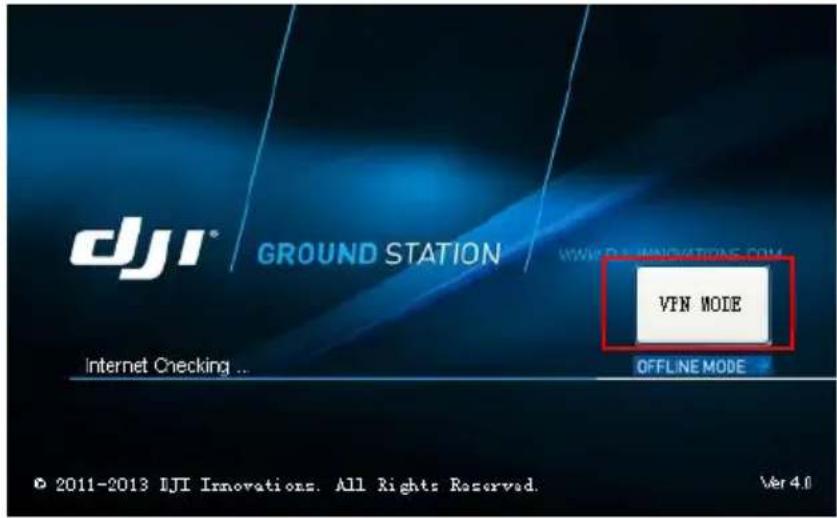
Since some areas set restriction to network access, the GS cannot access to the Google sever, which leads to the failure in opening the map. Please use the VPN mode to launch the GS, by clicking the "VPN Mode" button signed by the red line.
If the Connect button is gray and can't be clicked after launch the Ground Station.
Solution:
Please take the following steps to uninstall the Google Earth plugin, Start→All Program→Google Earth→Uninstall Google Earth Plug-in, and then use the installation CD to re-install the Google Earth plugin for DJI.
→ Connection failure after click the
Solution:
- Please choose the right COM port, and make sure that the driver is installed correctly.
● Make sure the transmitter and the receiver of the station are powered on.
● Make sure the transmitter and the receiver are matched; do not change the setup of switches on the radio station.
- Close the Assistant Software to avoid the port confliction.
Instrument Board Failure
The Ground Station launching failure when you click to open the instrument board; the reason is that your computer can't support the OpenGL.
Solution:
You may choose the Style2 (shown in Fig.①, ②) in System Setting→Options before you open the instrument board.
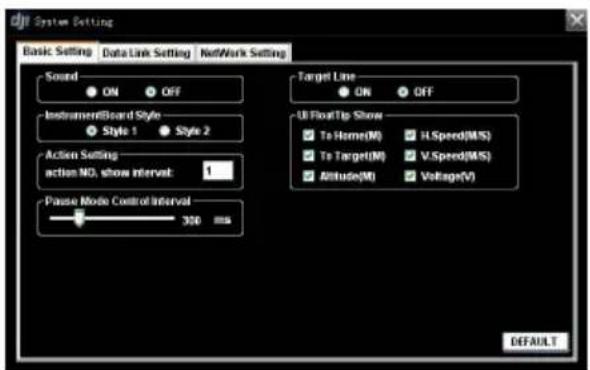
Fig①
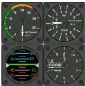
Fig②
Ground Station Software Crash
→ Ground Station Software Crash will not affect the aircraft under mission execution. The aircraft will keep going on the flight mission edited even the Ground Station Software crash. The Ground Station Software can be launched again, but loss of the following information will happen: Altitude Offset value, Aircraft tracks and Way points.
Solution:
Click on the DOWNLOAD button, to retrieve the previously set way points from the DJI Autopilot main
controller.
Launch Flight Failure
→ Aircraft doesn't execute mission after click on GO.
Solution:
- If aircraft is in the air, please ensure it is in Autopilot Mode, and there is no need to set center
position.
- If aircraft is on the ground and does not takeoff, please use Assistant Software to setup the center position and the throttle servo working range.
- If Auto Takeoff fails, you may take off the aircraft and then land manually in autopilot mode, then wait until throttle cut off automatically; or reboot the flight control system to initialize the controller.
Action Usage Faults
→ If there is no output change on F4 channel (ACE) / F2 channel (A2) / F1 channel (WKM/NAZA-M/NAZA-M V2) when click on the Trigger in the Action Setting window after connect to main controller.
Solution:
- Please ensure the receiver has been connected.
- Please ensure it is under the Autopilot Mode or Waypoint Mode.
- The action will not be valid unless the value of hold time is more than one second.
When Wireless Data-Link Doesn't Work
→ If your Ground Station cannot be connected with the main controller, please check the following issues.
Solution:
● Make sure radio driver have been installed.
- If the Antenna is broken, the communication distance cannot be guaranteed.
- Two Wireless Data-Link Terminals had been placed too close. The valid communication distance between 2.4GHz wireless data-links should be longer than 1.5 meters; the valid communication distance between 900MHz wireless data-links should be longer than 5 meters.
Data-link LED Introduction
| Function | Introduction | |
| Ground End | ||
| LINK-ALARM | Distance Alarm | Light on indicates distance warning. |
| LINK-ALARM | Network Light | Light on indicates communication is on with air end. |
| DATA-POWER | Power Light | Light on indicates working well. |
| DATA-POWER | Data Light | Light flash indicates data transmit and receive. |
| Air End | ||
| Link | Data Light | Light on indicates communication is on. |
| Power | Power Light | Light on indicates working well. |
| TX | Transmit Light | Light on indicates data transmit. |
| RX | Receive Light | Light on indicates data receive. |
Wireless Data-link Specification
| 2.4GHz | 900MHz | |
| Performance | ||
| RF Data Rate | 700kbps | 100kbps |
| Indoor/Urban Range | ≤500m | ≤1Km |
| Outdoor/RF Line-of-Sight Range | ≤3km | ≤10Km |
| Transmit Power | 130mW | 1000mW |
| Receiver Sensitivity (1%PER) | -95dBm | -110dBm |
| Power Consumption | Ground end: 460mW | Ground end: 1600mW |
| Air end: 460mW | Air end: 1500mW | |
| Features | ||
| Frequency Band | 2.4GHz(2400MHz ~2483MHz) | 900MHz(902MHz ~928MHz) |
| Serial Data Rate | 115200 bps | 115200 bps |
| Antenna Options | SMA | SMA |
| Operating Temperature | -40°C ~+85°C | -40°C ~+85°C |
| Operating Humidity | 0~95% | 0~95% |
| Size (No Antenna) | Ground end: 70x48x17mm | Ground end: 78x47.8x17mm |
| Air end: 51x37x10mm | Air end: 73x42x10mm | |
| Weight (Has Antenna) | Ground end: 55g | Ground end: 100g |
| Air end: 20g | Air end: 60g | |
| Power Requirement | ||
| Supply Voltage | 4.5V~12V | 4.5V~12V |
| Transmit Current | 220mA | 1300mA |
| Receive Current | 62mA | 100mA |
| Regulatory Approvals | ||
| FCC (USA) | Yes | Yes |
| IC (Canada) | Yes | Yes |
Flight Limit of Special Areas
All UAV operators should abide by all regulations from such organizations at ICAO (International Civil Aviation Organization) and per country airspace regulations. For safety reasons, key areas have been restricted, such as:
a) Within the radius of 8Km from the airport.
Users will not be able to build waypoints or Home points in designated special areas and the waypoint routines go through these special areas are invalid, and the UAV will fail to cruise to those areas.
All the special areas have been restricted are specified on the DJI official website and please refer to Special Areas List (http://www.dji.com/fly-safe/category-gs) to obtain details.
- Ground Station Wireless Data-link User Manual
- Disclaimer
- Profile
- In Box
- Wireless Data-link Ground End × 1
- Wireless Data-link Air End 900MHz × 1 or 2.4GHz × 1
- USB Cable × 1
- 4-Pin Cable × 1
- Warranty Card × 1
- Contents
- Matters Need Attention
- Connection
- Ground Station Software
- Install Software
- Start Software
- Start Window
- Start the Application of GS
- (2)Connect to Main Controller
- Application
- Control Mode Switch
- GUI
- GUI Instruction
- Joystick:
- ToolBox:
- Sys\_set→Options:
- View Mode
- View Mode Procedures
- System Setting
- (1)Options
- Tips:
- Basic Setting
- Data Link Setting
- Altitude Offset Setting
- Data Record Folder
- Joystick/Keyboard Mode
- Simulator
- Notices:
- One Key Takeoff
- Successful takeoff message
- Error messages
- Joystick and Keyboard Mode
- Keyboard Mode
- Joystick Mode
- → Requirement
- → Technology Requirements
- → Connection
- → Calibration
- → Channel Mapping
- Joystick→Channel Mapping
- Click Go Mode
- Waypoint(Single Waypoint User Skip This)
- Waypoint Mode
- Instructions
- Flight Mission Setting
- → Add waypoints
- Add Point by Point
- Using Relative Coordinates Editor
- → Delete Way Points
- → Waypoint Properties Editing
- Altitude
- TurnMode
- Forward Flight Speed
- HeadDegree
- HoldTime
- → Mission Properties Editing
- MissionTimeLmt
- Route
- StartWayPoint
- VerticalSpeedLimitSetting
- Set Mission properties
- Mission Save
- (II) Upload Flight Mission
- (III) Take off Aircraft
- (IV) Switch to Autopilot Mode
- GO!!
- Auto Takeoff and Landing
- Auto Takeoff
- Auto Landing
- F Channel Controller
- General Purpose Servo Action (GP-Servo Action)
- GP-Servo Action Setting
- Way point Action Editing
- Six Pre-Programmed Route Templates
- Photogrammetry Tool
- Appendix
- Troubleshooting
- Ground Station Launching Failure
- Solution:
- Instrument Board Failure
- Ground Station Software Crash
- Launch Flight Failure
- Action Usage Faults
- When Wireless Data-Link Doesn't Work
- Flight Limit of Special Areas
Brand : DJI
Model : PC Ground Station
Category : Uncategorized