
Listen Four - Keyboard 4ms - Free user manual and instructions
Find the device manual for free Listen Four 4ms in PDF.


| Product Type | MIDI Keyboard Controller |
| Number of Keys | 49 velocity-sensitive keys |
| Dimensions | 32.5 x 18.5 x 4.5 cm |
| Weight | 1.2 kg |
| Power Supply | USB bus-powered or 9V DC adapter (not included) |
| Connectivity | USB-B, MIDI Out, Sustain Pedal input |
| MIDI Channels | 16 channels, selectable via panel controls |
| Control Assignments | 4 programmable knobs, pitch bend wheel, modulation wheel |
| Compatibility | Windows, macOS, iOS (via Camera Connection Kit) |
| Main Functions | MIDI note triggering, real-time control, transport control via assignable buttons |
| Display | 2-digit LED for program number and MIDI channel |
| Built-in Sounds | No, it is a MIDI controller only |
| Operating Temperature | 0°C to 40°C |
| Storage Humidity | 5% to 85% non-condensing |
| Cleaning and Maintenance | Wipe with a dry soft cloth. Do not use solvents or abrasive cleaners. |
| Safety | Keep away from water and heat sources. Use only approved power adapters. |
| Spare Parts | USB cable, power adapter (optional) |
| Repairability | User-serviceable parts: none. Contact authorized service center for repairs. |
| General Information | Brand: 4ms; Model: Listen Four; Category: Keyboard |
Frequently Asked Questions - Listen Four 4ms
User questions about Listen Four 4ms
0 question about this device. Answer the ones you know or ask your own.
Ask a new question about this device
Download the instructions for your Keyboard in PDF format for free! Find your manual Listen Four - 4ms and take your electronic device back in hand. On this page are published all the documents necessary for the use of your device. Listen Four by 4ms.
USER MANUAL Listen Four 4ms
Listen Four 4ms Company
User Manual 1.0 - Dec 31, 2018
flowchart
graph TD
    A["1: Top Panel"] --> B["Pan I"]
    B --> C["Level 1"]
    D["2: Middle Panel"] --> E["Pan 2"]
    E --> F["Level 2"]
    G["3: Bottom Panel"] --> H["L R"]
    H --> I["Level 3"]
    J["4: Bottom Panel"] --> K["L R"]
    K --> L["Level 4"]
    M["Main Level"] --> N["Left Right"]
    O["LISTEN FOUR"] --> P["Ground"]
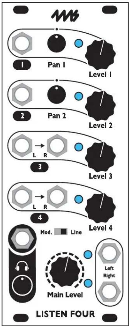
The Listen Four is a four channel stereo mixer with line, modular, and headphone outputs. Two mono channels with Pan knobs and two stereo channels with dual inputs provide optimal compatibility with both stereo and mono signals. The Listen Four can be daisy-chained to other Listen modules to create a larger mixer with sub-mix outputs. Listen Four features include:
• Four input channels (two with stereo inputs, two with mono inputs and a Pan knob)
- Headphone and main 1/8" outputs, each with separate Level knob
• Line level output driver with zero impedance, capable of driving long cables
- Output can be switched between line and modular level
- Low noise, cross-talk, and bleed-through
- Anti-pop feature that silences pops and thumps when the power is turned on
- Headers in back allow for connecting to other Listen Four or Listen Four Quarters modules to create a mixer with 8, 12, 16, or more channels and multiple sub-mix outputs
- Connects via headers to WAV Recorder module for recording final mix without using patch cables
• Signal lights for each channel and output mix
- Clipping lights with adjustable level
Table of Contents
Setting up your Listen Four ....3
Inputs....3
Main Outputs ....3
Headphones Output 4
Trim Pot (Clipping Light Level)....4
INS Header ....5
OUTS Header....5
Daisy-chaining 5
Anti-pop circuitry 7
Electrical and Mechanical Specifications 7
Setting up your Listen Four
- Power off your Eurorack system.
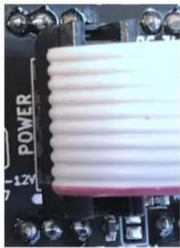
- Connect the free end of the included power cable to a 16-pin Eurorack power header on your power supply distribution system. The red stripe should match the white line or -12V marking on the power distribution board. The other end of the power cable is a 10-pin connector which should already be connected to the Listen Four with the red stripe on the power cable orientated towards the bottom of the module. Note: The Listen Four is reverse-polarity protected, but incorrectly connecting any module can damage any other on the power bus.
- Using the included screws, securely attach the Listen Four to the rails of your case.
- Power on your Eurorack system.
natural_image
Close-up of a power cord component mounted on a circuit board (no visible text or symbols)Inputs
The Listen Four has four input channels on the front. A fifth stereo channel can be accessed through a header on the back.

Level Knobs
All four channels have a Level knob. This knob sets the volume which will appear on the outputs. The Listen Four is very quiet, so turning the knob all the way down will completely mute the channel (over -100dB of attenuation, typically).

Channel Signal Lights
All four channels have a signal light which gets brighter as the signal gets louder. The color of the light indicates the stereo content: blue displays the signal on the left channel, and green displays the signal on the right channel. The signal light shows the signal post-fader (after the Level knob). These lights are useful for determining which channels are active at any given moment. However, they should not be used as precision indicators. For example, the green lights will appear dimmer than the blue lights at low audio levels and brighter than the blue lights at louder levels.

Channels 1 and 2: Panning
Channels 1 and 2 each have one input jack and a Pan knob. These channels accept a mono signal. Turning the Pan knob to the left or right will place the signal in the stereo field by fading it between the left and right outputs. The Pan knob has a small detent in the center position so you can find the center by feel.
The panning curve has been carefully designed to achieve the perception of a sound source being a consistent distance from the listener as it pans around.
Channels 3 and 4: Stereo inputs
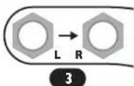
Channels 3 and 4 each have left and right input jacks. Patching a stereo signal into these jacks will accurately maintain the stereo image as the signal is mixed into the outputs. If you patch a mono signal into the left jack and nothing into the right jack, the mono signal will appear on both left and right outputs.
Channel 5: INS header
See INS header section below
Main Outputs

Main Level Knob
The Main Level knob controls the volume of the main left and right output jacks. When knob is turned fully to the left, the outputs are muted. Turning the knob the to right increases the volume. The maximum volume depends on the setting of the Mod/Line switch.

Mod. Line
Left and Right Output Jacks
The main outputs of the module are the left and right output jacks. The signal level on these jacks is controlled by the Main Level knob as well as the Mod/Line switch. These jacks have a zero-impedance line driver circuit capable of driving long cables. They also can be patched to other modules or an external DAW interface. The jacks are mono 1/8" (3.5mm).
While it is safe to use an adapter to convert to 1/4" (6.35mm), consider using the Listen Four Quarters module, which has balanced 1/4" outputs.
Output Signal Lights
The two lights near the output jacks indicate the signal level present on these jacks. The top light turns blue more brightly as the left channel output gets louder. If the left channel clips, a bright red light will add to the blue, creating purple. The lower light turns green more brightly as the right channel output gets louder. If the right channel clips, a red light will add to the green, creating yellow. The clipping level can be set with the trim pot on the back of the module (see Trim Pot section). When the switch is set to Line, no clipping can occur and these lights will never turn yellow or purple.
Mod/Line Switch
The Mod/Line switch selects what type of output occurs on the main output jacks. When set to Mod, modular level signals are output (+/-12V). When set to Line, line level signals are output. To protect your speakers, power off the Listen Four or disconnect the speakers before flipping this switch.
Note: The signal lights only indicate relative dynamics. Pulsing lights often indicate beats or throbbing sounds. It's normal that the blue lights are brighter than the green lights at softer volumes.
Headphones Output

Headphones Jack
The headphones jack is a stereo 1/8" jack (3.5mm) designed for outputting to headphones. Any headphones can be used, though 8 to 32 ohms is recommended. The jack can also be used as an additional output to connect to an external device that requires a TRS stereo signal. However, use the main outputs if possible because the frequency response and noise specifications of the headphones output are not as good as the main output jacks, and this output does not have the anti-pop circuitry.
Headphones Level Knob
This knob sets the headphones volume. It's independent of the Main Level knob and the Mod/Line switch.
Trim Pot (Clipping Light Level)
natural_image
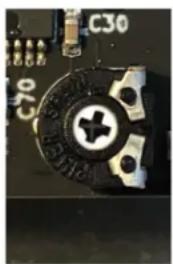
Close-up of a mechanical component with a circular dial and mounting holes (no visible text or symbols)A small trim pot on the back of the module adjusts the level at which the clip lights turn on (see Output Signal Lights section above). The factory default setting is for the lights to turn bright yellow or purple when the output signal exceeds about 20V peak-to-peak. When the trim pot is turned all the way counter-clockwise, the clip lights will almost never turn on, even though substantial clipping may be occurring. By turning the trim pot further clockwise, the clip level can be adjusted as low as 13.3V (-4.4dB).
To adjust the clipping level, use a #1 Phillips-head screwdriver and gently turn the inner shaft of the trim pot. If you feel any resistance, stop turning immediately: the trim pot can be easily damaged.
Turning clockwise will decrease the level (clip light turns on sooner). Turning counter-clockwise will increase the level.
The trimpot only adjusts the visual feedback from the clipping lights. It does not change the actual clipping.
Tip: After adjusting the trim pot, make sure the switch is set to Mod when you test the new level: no clipping ever occurs with the switch set to Line!
INS Header
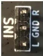
A three-pin header labeled INS on the back of the Listen Four allows you to connect another module as an auxiliary stereo input. Whatever signal is fed into the header will appear on the outputs without any attenuation. The INS header has pins for the left channel (bottom pin), right channel (top pin), and ground (center pin). The input impedance is 47k.
A typical use would be to daisy-chain multiple Listen modules to create a mixer with eight or more channels. To do this, the OUTS header on one module is connected to the INS header on the other module. See the Daisy-chaining section for details.
Another use would be to connect a 1/4" (6.35mm) adaptor module such as the Listen Up. This would allow you to use a stereo signal on two 1/4" cables as a fifth stereo input channel.
OUTS Header

A three-pin header labeled OUTS on the back of the module allows you to send the main output mix to another module with a compatible header. The pin order and pin dimensions of this header are the same as the INS header (see previous section). The output impedance is 1k. It will not damage the circuitry if the pins are shorted to ground.
The Main Level and Mod/Line switch will effect the level on the OUTS header. If you're connecting to another Listen module, it's recommended to flip the switch to Mod. If you're connecting to a 1/4" adaptor module and you require line-level outputs, flip the switch to Line. The Main Level knob acts as a volume knob. The main outputs and headphone outputs will still be active and are unaffected by the use of the OUTS header.
Daisy-chaining

natural_image
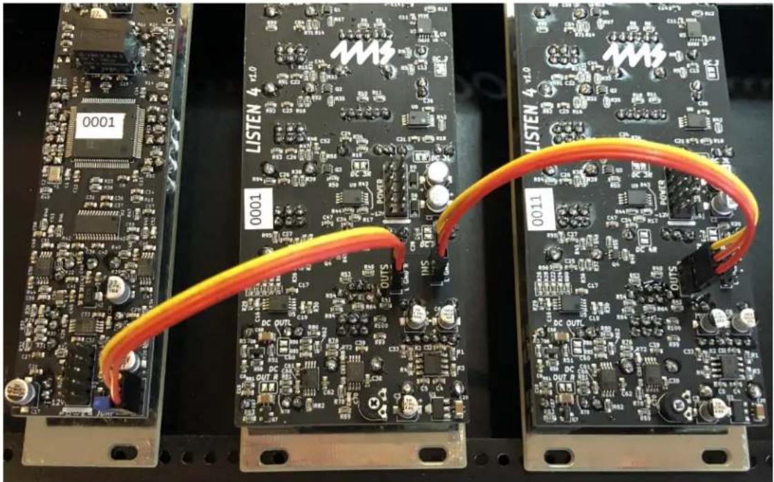
Close-up of two electronic circuit boards with visible components and orange cable routing (no readable text or symbols)Multiple Listen modules can be connected to form a large mixer. For example, connecting two Listen Four modules creates an eight channel stereo mixer: the four inputs of the first Listen Four are added to the four inputs of the second Listen Four (see photo on the left).
You can daisy-chain as many modules as you want. Connecting a Listen Four Quarters after the two Listen Fours in the example above will create a 12 channel mixer with 1/4" balanced outputs, and two sub-mix outputs.
You can also connect a WAV Recorder module to the end of a chain of Listen modules, allowing you to record the main outputs without using patch cables.
How to Daisy-chain
To daisy-chain two modules, use a 3-pin cable to connect the OUTS header of one module to the INS header of another. You can continue to connect more modules in the same way, OUTS to INS. A suitable connecting cable can be purchased from 4ms Company or many of our dealers. You also can find or create your own cable. The cable must fit a single row of three pins with a pin spacing of 0.1" (2.54mm). The pins are 0.2" tall (5mm), which is the same spacing, size and length as the pins on standard Eurorack power headers. Make sure the same color wire is on top on both sides of the connecting cable. If one side is reversed, the left and right channels will be reversed (though no damage or malfunction will occur).
Main Mixes and Sub-mixes
The Main Level knob controls the level that's passed to the next Listen module via the OUTS header. By patching related signals into the same Listen module, you can create sub-mixes with a single knob for level control.
For example, see the photo above. Two Listen Four modules are connected such that one module's OUTS header connects to the other module's INS header. Let's say you patch some polyrhythmic drum sounds into the first Listen Four, and patch some processed field recordings into the second Listen Four. The output jacks on the second Listen Four will be a mix of everything (the drums and field recordings), and the Main Level knob will control the overall level. The output jacks on the first Listen Four will be a sub-mix of just the drums, and its Main Level knob will control just the level of the drums in both the sub-mix and the overall mix.
Connecting to the WAV Recorder
The WAV Recorder just has an INS header, and so it can only be connected at the end of a daisy-chain. This is useful for making a recording of the main mix. Since the WAV Recorder can accept line or modular level signals, the Listen Four's switch can be set to either Line or Mod. The Input Gain knob on the WAV Recorder can be adjusted to the maximum recording level without clipping. Adjusting this knob will not effect the output level of the Listen modules.
natural_image
Three electronic circuit boards labeled 0001, 0001A, and 0011 connected by orange cables (no readable text or symbols beyond labels)In the photo above, two Listen Fours and a WAV Recorder are daisy-chained by connecting the OUTS to INS headers. This creates an eight channel mixer with a stereo recording of the main mix.
The photo on the right shows a twelve channel mixer with stereo recording of the main mix. Patching into any of the twelve channels will pass the signal to the 1/4" outputs, as well as the WAV Recorder. No cables need to be patched between modules. Each Listen module's Main Level knob controls the sub-mix level of its four channels plus the module to the left of it. The sub-mix can be taken simply by patching into the Left and Right output jacks on the Listen Four modules. The headphone jack on these modules can also be used to cue or monitor the sub-mix.

Twelve channel mixer with two four-channel sub-mixes, 1/4" balanced stereo outputs and stereo recording directly from the main mix. Each sub-mix has a headphone jack with independent level for cueing.
Anti-pop circuitry
The Listen Four has a special feature that prevents the main outputs from popping or thumping when the power is turned on. This avoids a common problem that happens when the power is accidentally turned off and back on again while connected to a PA or powered speaker system, or the power is turned on after the speakers are turned on. When using most mixers, the result is a loud pop that can damage the speakers (and frighten anyone nearby!). The Listen Four automatically mutes the outputs during power-on, thus avoiding any pops.
Electrical and Mechanical Specifications
• 10HP Eurorack format module
- 0.98" (25mm) maximum depth (includes power cable)
• 10-pin Eurorack power header
• Power consumption
• Maximum values without using headphones jack:
Main outputs shorted to ground, headphones jack not used, maximum signal levels on all channels
• Maximum values in worst-case conditions:
All outputs including headphone jack shorted to ground, maximum signal levels on all channels
• +12V: 200mA
-12V: 62mA
- Main outputs
• Output type: zero-impedance, compensated for electrolytic capacitor distortion
• Frequency Response: +/-0.2dB max deviation, 10Hz - 20kHz
• Maximum output level: 22.2V peak-to-peak
• Maximum gain of channels 1 and 2: 8.0dB (hard-panned), 3.1dB (center-panned)
• Maximum gain of channels 3 and 4, and INS header: 4.9dB
- Channel bleed-through (Main Level attenuation):
Test conditions: Test signal input into each channel with Level knob at 100%. Frequencies from 20Hz to 20kHz tested. Result given as a ratio of the signal measured on main output jacks with Main Level knob at 0%, to the signal measured with Main Level knob at 100%. Worst-case results for any channel and frequency reported.
• Left output jack: -102dB
• Right output jack: -90dB
• Channel bleed-through (channel attenuation):
Test conditions: Test signal input into each channel with Level knob at 0% and Main Level knob at 100%. Frequencies from 20Hz to 20kHz tested. Result given as a ratio of the signal measured on main output jacks with channel Level knob at 0%, to the signal measured with channel Level knob at 100%. Worst-case results for any channel and frequency reported.
- Left output jack: channel 4: -90dB at 20kHz; all other channels -110dB
• Right output jack: channel 4: -84dB at 20kHz; all other channels -110dB
• Channel cross-talk:
Test conditions: Test signal input into each channel. Level knob at 0%, and other channel Level knobs at 100%. Main Level knob at 100%. Frequencies from 20Hz to 20kHz tested. Measured signal subtracted from signal with all Level knobs at 0%, and result given in dB as a ratio to output signal with test channels' Level knob at 100%. Worst-case results for any channel and frequency reported.
• Left output jack: -110dB
• Right output jack: -102dB
- Headphones jack
- Frequency response: -0.2dB at 20Hz; 0dB at 100Hz to 20kHz (driving 32Ω headphones)
• Maximum voltage (peak-to-peak): 5Vpp
- Listen Four 4ms Company
- Table of Contents
- Setting up your Listen Four
- Inputs
- Level Knobs
- Channel Signal Lights
- Channels 1 and 2: Panning
- Channels 3 and 4: Stereo inputs
- Channel 5: INS header
- Main Outputs
- Main Level Knob
- Left and Right Output Jacks
- Output Signal Lights
- Mod/Line Switch
- Headphones Output
- Headphones Jack
- Headphones Level Knob
- Trim Pot (Clipping Light Level)
- INS Header
- OUTS Header
- Daisy-chaining
- How to Daisy-chain
- Main Mixes and Sub-mixes
- Connecting to the WAV Recorder
- Anti-pop circuitry
- Electrical and Mechanical Specifications
- • Power consumption
- - Main outputs
- - Headphones jack
Brand : 4ms
Model : Listen Four
Category : Keyboard