
Rotating Clock Divider - Keyboard 4ms - Free user manual and instructions
Find the device manual for free Rotating Clock Divider 4ms in PDF.


| Product Type | Eurorack Module |
| Brand | 4ms |
| Model | Rotating Clock Divider |
| Width | 8 HP |
| Depth | 25 mm |
| Weight | 80 g |
| Power Supply | +12V: 50 mA, -12V: 10 mA |
| Power Connector | 16-pin Eurorack ribbon cable |
| Functions | Clock division by 1 to 16, rotation, tap tempo, reset |
| Outputs | 16 individual clock outputs (3.5mm jacks) |
| Inputs | Clock input, reset input, rotate CV input (3.5mm jacks) |
| Controls | Rotary encoder for division and rotation, tap button |
| LED Indicators | 16 output LEDs, power LED |
| Construction | PCB, aluminum panel |
| Maintenance | Keep dry; clean with a soft, dry cloth |
| Safety | Disconnect power before installation or removal; handle with care |
| Spare Parts | Contact 4ms for replacement jacks or encoder |
| Repairability | Designed for easy repair; user-serviceable components |
| Warranty | 1 year limited warranty |
| General Information | Manufactured in the USA by 4ms Company |
Frequently Asked Questions - Rotating Clock Divider 4ms
User questions about Rotating Clock Divider 4ms
0 question about this device. Answer the ones you know or ask your own.
Ask a new question about this device
Download the instructions for your Keyboard in PDF format for free! Find your manual Rotating Clock Divider - 4ms and take your electronic device back in hand. On this page are published all the documents necessary for the use of your device. Rotating Clock Divider by 4ms.
USER MANUAL Rotating Clock Divider 4ms
Rotating Clock Divider
Eurorack Module User Manual (updated Sept 2015)
PCB version 1.2 (released November 2014)
Firmware version 1.1 (released April 2012)
4ms Pedals

Features
- Divide-by-1 to Divide-by-64, on 8 output jacks
•CV Rotate jack to shift divide-by amount on all jacks
•CV Reset to reset/re-sync all jacks
- Jumpers or optional break-out panel:
Select auto-reset
- Select "Spread" mode
- Gate or Trigger outputs
- Count-up or Count-down mode
- Select maximum divide-by amount (8/16/32/64)
-ISP header
- Connects to in-circuit programmer such as AVR ISP MKII for reprogramming code
•Maximum input frequency 3kHz
- LED dimmer trimpot allows you to set a custom LED brightness
- Bus Clock support (slave only). Clock can be taken from the Gate pins on the power header.
- 5V Select jumper allows you to power the RCD from either the 12V rail or the 5V rail.
•4 HP Eurorack module
-5VSEL Jumper set to INT:
- 33mA maximum power draw from +12V rail
- 0mA max on the +5V rail
- 4mA maximum power draw on the -12V rail
•5VSEL Jumper set to EXT:
- 19mA maximum power draw on the +12V rail
- 14mA max on the +5V rail
- 4mA maximum power draw on the -12V rail
Jacks
•Clock Input (3.5V to 15V clock, rising edge triggered)
•CV Rotate (0V to +5V input)
•CV Reset (3.5V to 15V trigger)
•Divided Clock Outputs (8 jacks):
•Divide-by (1+R)
•Divide-by (2+R)
- Divide-by (3+R)
- Divide-by (4+R)
•Divide-by (5+R)
- Divide-by (6+R)
•Divide-by (7+R)
•Divide-by (8+R)
•..where R is the CV Rotation (0 to 63)

The breakout header on the back of the PCB has spots for 6 jumper shunts which enable/disable features and change the operation of the RCD. You also can attach an RCD Breakout module, which makes changing settings convenient and accessible.
If you don't have an RCD Breakout, you can set the RCD to operate in a particular mode by installing certain jumpers, and omitting others.
Note: The bottom four pins of the breakout header have been snipped off or have been omitted at the factory.
Counting Up/Down:
| Up/Down | Mode |
| on Down | counting |
| off Up counting | |
Trigger/Gate:
| Trig/ Gate | Mode |
| on Gate | |
| off Trigger | |
Auto-Reset:
| Auto-ResetJumper | Auto-reset amountwith Max-Divide-by range of... | |||
| 8 16 32 64 | ||||
| on 16 | 32 64 128 | |||
| off none | none none | none | ||
Max Divide-by Range and Spread Mode:
| Max-Divide Range Jumpers | Total Rotatable Divide-by range | Default Divide-by amount on jacks with no voltage applied to CV Rotate jack (tables 2-5)(Applying CV to Rotate jack makes each output increase by 1)See also Table 5 below | ||
| 16 | 32 S | Spread off | Spread on | |
| on | on | 1 to 8 | 1, 2, 3, 4, 5, 6, 7, 8 | 1, 2, 3, 4, 6, 8, 12, 16 |
| on | off | 1 to 16 | 9, 10, 11, 12, 13, 14, 15, 16 | 2, 4, 6, 8, 10, 12, 14, 16 |
| off | on | 1 to 32 | 17, 18, 19, 20, 21, 22, 23, 24 | 4, 8, 12, 16, 20, 24, 28, 32 |
| off | off | 1 to 64 | 33, 34, 35, 36, 37, 38, 39, 40 | 8, 16, 24, 32, 40, 48, 56, 64 |
Gate/Trigger Mode:
In Trigger mode, the jacks output a pulse width equal to that of the input clock (the pulse width is not multiplied or divided proportionally to the jack's divide-by amount). This is the default method for pcb v1.0 and v1.0.1, unless it has been upgraded to v1.0.2 or later firmware. In Gate mode, the width of the output pulses are 50% of the total wave. For example, the /6 jack will stay ON for 3 clock pulses, and then turn OFF for 3 clock pulses. For even numbered divisions (/2, /4, /6, /8, etc) the transitions happen on the input clock's rising edge. Point of interest: In Gate mode, with odd-numbered divisions, the jack will turn ON on a rising edge of the input clock, and then will turn OFF on a falling edge. For example, the /5 jack ought to stay on for 2.5 clock pulses, meaning it should go OFF somewhere between the rising edge of clock pulses 2 and 3. Right in between these is the falling edge of pulse number 2, so we can safely call it 2.5!
When in Gate mode, the difference between Up and down-counting is that the gates are inverted.
Up-beat/Down-beat counting:
In Up-beat counting, each jack fires after "N" number of pulses are counted on the input jack (where N is the divide-by-number). So, after a Reset pulse, only the /1 jack will fire after a Reset on the first clock pulse. On the next clock pulse, the /1 and the /2 jack will fire, then on the next pulse the /1 and /3 jacks will fire, etc...
In Down-counting, each jack fires when its count is 1. So all the jacks will fire after a Reset pulse, and then count up to "N", and fire again when they start over at 1. This is called "down-beat counting" because all the jacks fire on the down-beat (first clock pulse).
Clock outputs (up-beat counting):
| IN: | 1 | 2 | 3 | 4 | 5 | 6 | 7 | 8 | 9 | 10 | 11 | 12 | 13 | 14 | 15 | 16 | 17 | 18 | 19 | 20 | 21 | 22 | 23 | 24 | 25 | 26 | 27 | 28 | 29 | 30 | 31 | 32 |
| 1 | X | X | X | X | X | X | X | X | X | X | X | X | X | X | X | X | X | X | X | X | X | X | X | X | X | X | X | X | X | X | X | X |
| 2 | X | X | X | X | X | X | X | X | X | X | X | X | X | X | X | X | ||||||||||||||||
| 3 | X | X | X | X | X | X | X | X | X | X | ||||||||||||||||||||||
| 4 | X | X | X | X | X | X | X | X | ||||||||||||||||||||||||
| 5 | X | X | X | X | X | X | ||||||||||||||||||||||||||
| 6 | X | X | X | X | X | |||||||||||||||||||||||||||
| 7 | X | X | X | X | ||||||||||||||||||||||||||||
| 8 | X | X | X | X |
| 32 | X |
Clock outputs (down-beat counting):
| IN: | 1 | 2 | 3 | 4 | 5 | 6 | 7 | 8 | 9 | 10 | 11 | 12 | 13 | 14 | 15 | 16 | 17 | 18 | 19 | 20 | 21 | 22 | 23 | 24 | 25 | 26 | 27 | 28 | 29 | 30 | 31 | 32 |
| 1 | X | X | X | X | X | X | X | X | X | X | X | X | X | X | X | X | X | X | X | X | X | X | X | X | X | X | X | X | X | X | X | X |
| 2 | X | X | X | X | X | X | X | X | X | X | X | X | X | X | X | X | ||||||||||||||||
| 3 | X | X | X | X | X | X | X | X | X | X | X | |||||||||||||||||||||
| 4 | X | X | X | X | X | X | X | X | ||||||||||||||||||||||||
| 5 | X | X | X | X | X | X | X | |||||||||||||||||||||||||
| 6 | X | X | X | X | X | X | ||||||||||||||||||||||||||
| 7 | X | X | X | X | X | |||||||||||||||||||||||||||
| 8 | X | X | X | X |
Spread mode:
Spread mode causes the output to "spread" evenly amongst the entire max division range. See the "Jumper 3, 4, and 5" table on the previous page. For instance, if Max-Div is set to 32, then in spread mode the jacks will output divisions evenly spaced from 1 to 32 (pus whatever rotation is applied). Since there are 8 jacks spread over 32 values, each jacks will always be offset by 4 divisions from its neighbors. See Table 4. For example:
With no CV at the Rotate jack, the jacks will output:
/4, /8, /12, /16, /20, /24, /28, /32
Applying a small amount of CV to the Rotate jack will make each jack increment by 1:
/5, /9, /13, /17, /21, /25, /29, /1
Applying more CV Rotation will shift them further. Note how the difference between each jack is 4.
/6, /10, /14, /18, /22, /26, /30, /2
A different thing happens when Max-Divide-by is set to 8. In this case, the jacks will only output standard "musical" divisions of triplets and sixteenth-notes:
/1, /2, /3, /4, /6, /8, /12, /16
Adding a little bit of CV Rotation will shift the outputs to
Adding more Rotation will shift them more.
/3, /4, /6, /8, /12, /16, /1, /2
In all cases, the outputs will be limited to these "musical" divisions with Spread On and Max-Div at 8
Auto Reset:
Jumper 6 selects the Auto-reset point, which causes the divide counters to reset after a certain number of clock pulses. Note that divide-by amounts which are evenly dividable by the reset amount are not affected: e.g. with an auto-reset of 16, divide-by outputs of 2, 4, 8, 16, etc are not changed.
Also, note that the CV Reset is independent of the Auto-reset. For example, Jack 7+R could be patched into the CV Reset with jumpers 3, 4, and 5 in. This would cause a reset every 7 clocks, plus an additional reset every 16 clocks.
There are too many combinations of Auto-reset and Max divide amounts to show all combinations!
Example: Auto-reset of 16 (Jumper 6 in), with Max Divide-by of 8 (Jumpers 3&4 in)
| IN: | 1 | 2 | 3 | 4 | 5 | 6 | 7 | 8 | 9 | 10 | 11 | 12 | 13 | 14 | 15 | 16 | 17 | 18 | 19 | 20 | 21 | 22 | 23 | 24 | 25 | 26 | 27 | 28 | 29 | 30 | 31 | 32 |
| 3 X | X X | X X X | X X | X X | ||||||||||||||||||||||||||||
| 5 X | X X | X X X | ||||||||||||||||||||||||||||||
| 7 | X | X | X | X |
Bus Clock (PCB version 1.2)

The RCD can be clocked by a master clock running on the Gate bus of the power header. If you have a master clock module that supplies a clock to the bus, you can take advantage of this by installing the BUS CLK jumper on the back of the RCD. The bus clock is buffered on the RCD, so there is no loading effect on the clock signal.
With the jumper installed by placing it on both pins, the RCD will be clocked by the bus clock. Patching a cable into the Clock In jack on the RCD will override the bus clock.
With the jumper not installed the Bus Clock will not be used. The jumper can be placed on one pin (either one is fine) so that you don't loose.
Factory setting is Bus clock disabled, jumper installed on only one pin (shown on the left).
5V Select (PCB version 1.2)

Jumping the side marked "INT" will power the RCD from the +12V rail, using an internal regulator chip. Jumping the side marked "EXT" will power the RCD from the +5V rail.
When the RCD is in "EXT" mode, less current is drawn from the +12V rail, but if there is noise on the 5V rail, the RCD may glitch. If you are experiencing problems, try setting the jumper to "INT".
Factory setting is "INT" mode (shown on the left).
LED Dimmer Trimpot (PCB version 1.2)

The LEDs on the RCD can be dimmed or brightened by adjusting a trimpot. Use a very small phillips screwdriver (#00 or #000) to adjust the trimpot. Be careful and gentle as you adjust the trimpot. It's safe to adjust the trimpot while the RCD is powered on, but be careful not to touch any components or solder junctions on the board.
The factory default is about 50%.
Operation
Apply a clock signal to the Clock Input jack. Rising edges of 5V or greater will cause the internal dividing counters to be incremented. Each jack has its own counter that counts from 1 to its divide-by-amount, and then resets back at 1. In up-beat counting, each jack outputs a trigger pulse when its counter reaches the divide-by amount assigned to that jack. In down-beat counting, each jack fires when its counter is 1. Typically, the outputs will patch to trigger-able or gate-able modules (drum modules, ADSR envelope/transient generators, step sequencer clock input, etc.), but the RCD can also operate in the audio frequency range, thus crudely stepping pitch downward.
CV Rotation
By applying a CV signal to the CV Rotate jack, the clock divisions will rotate throughout the output jacks (see table 2). For example, if you apply just over 1.0V, Jack 1+R/Red will go from Divide-by-1 to Divide-by-2, and Jack 2+R/Orange will become Divide-by-3... up to Jack 8+R/White which will wrap ("rotate") around to become Divide-by-1. Applying more CV to the Rotate Jack will continue the rotation: next Jack 1 becomes Divide-by-3, then Divide-by-4, then Divide-by-5, until it's Divide-by-8 at the maximum input CV. Some non-linearities exist in the CV response, especially in the upper extreme. See diagram at end of this manual.
CV Reset
Applying a CV of 3.5V or greater to the CV Reset jack will cause all the divide counters to reset on the next clock pulse. So, applying a reset pulse will not change the tempo, since the RCD will wait for the next clock pulse to actually do anything. Counting will begin back at 1 after a Reset. A low/slow output on the RCD can be patched into Reset, or a second RCD running on the same master clock can be set to run very slow and reset the first RCD after an arbitrary number of beats.
Rotation Tables
Table 1: Spread mode off, max divide-by amount set to 8
| Jacks | Spread off: Voltage at CV Rotate Jack | |||||||
| <0.67V 0.67V - 1.3V 1.3V - 1.9V 1.9V - 2.5V 2.5V - 3.2V 3.2V - 3.8V 3.8V - 4.5V >4.5V | ||||||||
| /1 | 1 | 2 | 3 | 4 | 5 | 6 | 7 | 8 |
| /2 | 2 | 3 | 4 | 5 | 6 | 7 | 8 | 1 |
| /3 | 3 | 4 | 5 | 6 | 7 | 8 | 1 | 2 |
| /4 | 4 | 5 | 6 | 7 | 8 | 1 | 2 | 3 |
| /5 | 5 | 6 | 7 | 8 | 1 | 2 | 3 | 4 |
| /6 | 6 | 7 | 8 | 1 | 2 | 3 | 4 | 5 |
| /7 | 7 | 8 | 1 | 2 | 3 | 4 | 5 | 6 |
| /8 | 8 | 1 | 2 | 3 | 4 | 5 | 6 | 7 |
Table 2: Spread mode on, max divide-by amount set to 8
| Jacks | Spread on: Voltage at CV Rotate Jack | |||||||
| <0.67V 0.67V - 1.3V 1.3V - 1.9V 1.9V - 2.5V 2.5V - 3.2V 3.2V - 3.8V 3.8V - 4.5V >4.5V | ||||||||
| /1 | 1 | 2 | 3 | 4 | 6 | 8 | 12 | 16 |
| /2 | 2 | 3 | 4 | 6 | 8 | 12 | 16 | 1 |
| /3 | 3 | 4 | 6 | 8 | 12 | 16 | 1 | 2 |
| /4 | 4 | 6 | 8 | 12 | 16 | 1 | 2 | 3 |
| /5 | 6 | 8 | 12 | 16 | 1 | 2 | 3 | 4 |
| /6 | 8 | 12 | 16 | 1 | 2 | 3 | 4 | 6 |
| /7 | 12 | 16 | 1 | 2 | 3 | 4 | 6 | 8 |
| /8 | 16 | 1 | 2 | 3 | 4 | 6 | 8 | 12 |
Table 3: Spread off, max divide-by amount set to 16
| Jacks | Spread off: Voltage at CV Rotate Jack | |||||||||||||||
| < 0.35 | 0.35-0.67 | 0.67 - 0.99 | 0.99-1.3V | 1.3V-1.6V | 1.6V-1.9V | 1.9V-2.2V | 2.2V-2.5V | 2.5V-2.8V | 2.8V-3.1V | 3.1V-3.4V | 3.4V-3.7V | 3.7V-4.0V | 4.0V-4.3V | 4.3V-4.7V | >4.7V | |
| /1 9 10 1 | 1 12 13 | 14 15 16 | 1 2 3 4 | 5 6 7 8 | ||||||||||||
| /2 10 11 | 12 13 14 | 15 16 1 | 2 3 4 5 | 6 7 8 9 | ||||||||||||
| /3 11 12 | 13 14 15 | 16 1 2 3 | 4 5 6 7 | 8 9 10 | ||||||||||||
| /4 12 13 | 14 15 16 | 1 2 3 4 | 5 6 7 8 9 | 10 11 | ||||||||||||
| /5 13 14 | 15 16 1 2 | 3 4 5 6 | 7 8 9 10 | 11 12 | ||||||||||||
| /6 14 15 | 16 1 2 3 | 4 5 6 7 8 | 9 10 11 | 12 13 | ||||||||||||
| /7 15 16 | 1 2 3 4 5 | 6 7 8 9 | 10 11 12 | 13 14 | ||||||||||||
| /8 16 1 2 | 3 4 5 6 7 | 8 9 10 | 11 12 13 | 14 15 | ||||||||||||
Table 4: Spread on, max divide-by amount set to 16
| Jacks | Spread on: Voltage at CV Rotate Jack | |||||||||||||||
| < 0.35 | 0.35-0.67 | 0.67 -0.99 | 0.99-1.3V | 1.3V-1.6V | 1.6V-1.9V | 1.9V-2.2V | 2.2V-2.5V | 2.5V-2.8V | 2.8V-3.1V | 3.1V-3.4V | 3.4V-3.7V | 3.7V-4.0V | 4.0V-4.3V | 4.3V-4.7V | >4.7V | |
| /1 2 3 4 5 | 6 7 8 9 | 10 11 12 | 13 14 | 15 16 1 | ||||||||||||
| /2 4 5 6 7 | 8 9 10 | 11 12 13 | 14 15 | 16 1 2 3 | ||||||||||||
| /3 6 7 8 9 | 10 11 12 | 13 14 | 15 16 1 | 2 3 4 5 | ||||||||||||
| /4 8 9 10 | 11 12 13 | 14 15 | 16 1 2 3 | 4 5 6 7 | ||||||||||||
| /5 10 11 | 12 13 14 | 15 16 1 | 2 3 4 5 | 6 7 8 9 | ||||||||||||
| /6 12 13 | 14 15 16 | 1 2 3 4 | 5 6 7 8 9 | 10 11 | ||||||||||||
| /7 14 15 | 16 1 2 3 | 4 5 6 7 8 | 9 10 11 | 12 13 | ||||||||||||
| /8 16 1 2 | 3 4 5 6 7 | 8 9 10 | 11 12 13 | 14 15 | ||||||||||||
Table 5: Spread on and off, max divide-by amount set to 32 and 64
| Max-Div: 32Spread: OFF | Max-Div: 32Spread: ON | Max-Div: 64Spread: OFF | Max-Div: 64Spread: ON | |
| Rotate threshold voltage | 0.16V 0.16V 0.07V | 0.07V | ||
| Range | 1-32 | 1-32 | 1-64 | 1-64 |
| Jack: | Divide-by amount with no Rotation (0V): | |||
| /1 | 17, 18, 19,... | 4, 5, 6... | 33, 34, 35... | 8, 9,10... |
| /2 | 18 | 8 | 34 | 16 |
| /3 | 19 | 12 | 35 | 24 |
| /4 | 20 | 16 | 36 | 32 |
| /5 | 21 | 20 | 37 | 40 |
| /6 | 22 | 24 | 38 | 48 |
| /7 | 23 | 28 | 39 | 56 |
| /8 | 24 | 32 | 40 | 64 |
Applying voltage to the Rotate CV jack will increase the Divide-by amount by 1 each time the threshold voltage is added. The threshold voltage is listed in the first line of the table above.
For example, look at the first column in the table (Max-Div 32 and Spread OFF). With no CV (0V) on the Rotate jack, the first output jack will divide the input clock by 17. If you apply 0.16V to the Rotate jack, the output will divide by 18. If you apply 0.32V, you'll get /19. At 0.48V you get /20... etc. Once get to /32, applying more votlage will rotate back around to /1, /2, /3... all the way back to /16.
TRIGGER MODE, UP-BEAT COUNTING

line
| Time | DIV INPUT | DIV by 1 | DIV by 2 | DIV by 3 | DIV by 4 | DIV by 5 | DIV by 6 | Div by 7 | Div by 8 | |------|-----------|----------|----------|----------|----------|----------|----------|----------|----------| | 1 | 1 | 1 | 1 | 1 | 1 | 1 | 1 | 1 | 1 | | 2 | 2 | 2 | 2 | 2 | 2 | 2 | 2 | 2 | 2 | | 3 | 3 | 3 | 3 | 3 | 3 | 3 | 3 | 3 | 3 | | 4 | 4 | 4 | 4 | 4 | 4 | 4 | 4 | 4 | 4 | | 5 | 5 | 5 | 5 | 5 | 5 | 5 | 5 | 5 | 5 | | 6 | 6 | 6 | 6 | 6 | 6 | 6 | 6 | 6 | 6 | | 7 | 7 | 7 | 7 | 7 | 7 | 7 | 7 | 7 | 7 | | 8 | 8 | 8 | 8 | 8 | 8 | 8 | 8 | 8 | 8 | | 9 | 9 | 9 | 9 | 9 | 9 | 9 | 9 | 9 | 9 | | 10 | 10 | 10 | 10 | 10 | 10 | 10 | 10 | 10 | 10 | | 11 | 11 | 11 | 11 | 11 | 11 | 11 | 11 | 11 | 11 | | 12 | 12 | 12 | 12 | 12 | 12 | 12 | 12 | 12 | 12 | | 13 | 13 | 13 | 13 | 13 | 13 | 13 | 13 | 13 | 13 | | 14 | 14 | 14 | 14 | 14 | 14 | 14 | 14 | 14 | 14 | | 15 | 15 | 15 | 15 | 15 | 15 | 15 | 15 | 15 | 15 | | 16 | 16 | 16 | 16 | 16 | 16 | 16 | 16 | 16 | 16 |GATE MODE, DOWN-BEAT COUNTING
↓ Indicates falling-edge of clock input (all others are rising-edge)

other
| DIV INPUT | Time 1 | Time 2 | Time 3 | Time 4 | Time 5 | Time 6 | Time 7 | Time 8 | Time 9 | Time 10 | Time 11 | Time 12 | Time 13 | Time 14 | Time 15 | Time 16 | |-----------|--------|--------|--------|--------|--------|--------|--------|--------|--------|---------|---------|---------|---------|---------|---------|---------| | div by 1 | 1 | 2 | 3 | 4 | 5 | 6 | 7 | 8 | 9 | 10 | 11 | 12 | 13 | 14 | 15 | 16 | | div by 2 | 1 | 2 | 3 | 4 | 5 | 6 | 7 | 8 | 9 | 10 | 11 | 12 | 13 | 14 | 15 | 16 | | div by 3 | 1 | 2 | 4 | 5 | 6 | 7 | 8 | 9 | 10 | 11 | 12 | 13 | 14 | 15 | 16 | | | div by 4 | 1 | 3 | 5 | 6 | 7 | 8 | 9 | 10 | 11 | 12 | 13 | 14 | | | | | | div by 5 | 1 | 4 | 5 | 6 | 7 | 8 | 9 | 10 | 11 | 12 | | | | | | | | div by 6 | 1 | 4 | 5 | 6 | 7 | 8 | 9 | | | | | | | | | | | div by 7 | 1 | 4 | 5 | 6 | 7 | 8 | | | | | | | | | | | | div by 8 | | | | | | | | | | | | | | | | | CLOCK INPUT: | | Div by 1: | | | | | | | | | | | | | | | | | | Div by 2: | | | | | | | | | | | | | | | | | | Div by 3: | | | | | | | | | | | | | | | | | | Div by 4: | | | | | | | | | | | | | | | | | | Div by 5: | | | | | | | | | | | | | | | | | Div by 6: | | | | | | | | | | | | | Div by 7: | | | | | | | | | | | | | Div by 8: | | | | | | | | | | | CLOCK INPUT: | | Div by 1: (approx) : / div by 2: (approx) / div by 3: (approx) / div by 4: (approx) / div by 5: (approx) / div by 6: (approx) / div by 7: (approx) / div by 8: (approx) / div by 9: (approx) / div by 10: (approx) / div by 11: (approx) / div by 12: (approx) / div by 13: (approx) / div by 14: (approx) / div by 15: (approx) / div by 16: (approx) / div by 17: (approx) / div by 18: (approx) / div by 19: (approx) / div by 20: (approx) / div by 21: (approx) / div by 22: (approx) / div by 23: (approx) / div by 24: (approx) / div by 25: (approx) / div by 26: (approx) / div by 27: (approx) / div by 28: (approx) / div by 29: (approx) / div by 30: (approx) / div by 31: (approx) / div by 32: (approx) / div by 33: (approx) / div by 34: (approx) / div by 35: (approx) / div by 36: (approx) / div by 37: (approx) / div by 38: (approx) / div by 39: (approx) / div by 40: (approx) / div by 41: (approx) / div by 42: (approx) / div by 43: (approx) / div by 44: (approx) / div by 45: (approx) / div by 46: (approx) / div by 47: (approx) / div by 48: (approx) / div by
4ms Rotating Clock Divider How CV Rotate Works
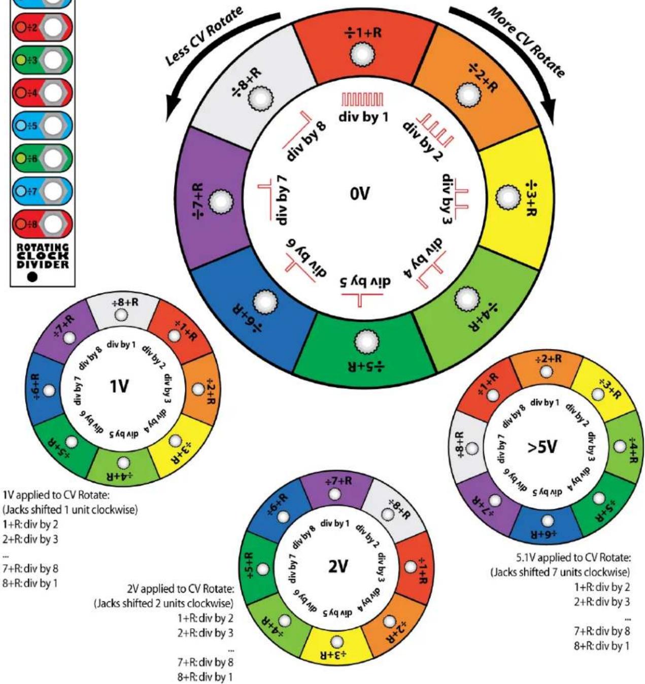
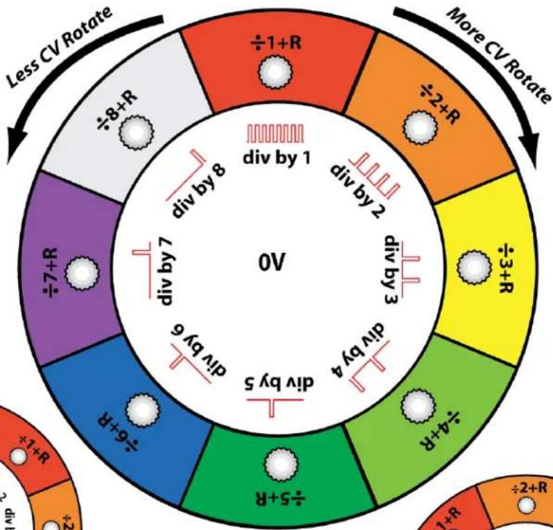
In this metaphorical illustration, applying a voltage to the Rotate jack makes the outer circle of jacks rotate around the inner circle of divided clock signals. For a technical chart of the exact voltages needed to cause exact rotations, see the User Manual.
This page assumes all jumpers are in their factory positions: i.e. only jumpers 3 and 4 are "in"
pie
| Rotation State | Divided States | | -------------- | -------------- | | Div by 1 | +1+R | | Div by 2 | +2+R | | Div by 3 | +3+R | | Div by 4 | +4+R | | Div by 5 | +5+R | | Div by 6 | +6+R | | Div by 7 | +7+R | | Div by 8 | +8+R | | More CV Rotate | - |
pie
1V | Segment | Value | |---|---| | div by 8 | 8 | | div by 7 | 8 | | div by 6 | 6 | | div by 5 | 5 | | div by 4 | 4 | | div by 3 | 3 | | div by 2 | 2 | | div by 1 | 1 | | div by 0 | 0 | +8+R | 0 | +7+R | 0 | +1+R | 0 | +6+R | 0 | +3+R | 0 | +2+R | 0 |1V applied to CV Rotate:
(Jacks shifted 1 unit clockwise)
1+R:div by 2
2+R:div by 3
7+R:div by 8
8+R:div by 1
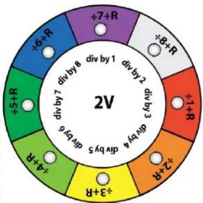
2V applied to CV Rotate: (Jacks shifted 2 units clockwise)
1+R:div by 2
2+R:div by 3
7+R:div by 8
8+R:div by 1
pie
| Category | Value | |---|---| | ÷6+R | 1 | | ÷7+R | 1 | | ÷8+R | 1 | | ÷1+R | 3 | | ÷2+R | 4 | | ÷3+R | 5 | | ÷4+R | 6 | | ÷5+R | 7 | | ÷6+R | 8 | div by 1 | 1 | div by 2 | 2 | div by 3 | 3 | div by 4 | 4 | div by 5 | 5 | 2V
pie
| Category | Value | |---|---| | ÷2+R | 0 | | ÷3+R | 0 | | ÷4+R | 0 | | ÷5+R | 0 | | ÷6+R | 0 | | ÷7+R | 0 | | ÷8+R | 0 | | ÷1+R | 0 | | div by 1 | >5V | | div by 2 | >5V | | div by 3 | >5V | | div by 4 | >5V | | div by 5 | >5V | | div by 6 | >5V | | div by 7 | >5V | div by 8 | >5V |5.1V applied to CV Rotate: (Jacks shifted 7 units clockwise)
1+R:div by 2
2+R:div by 3
7+R:div by 8
8+R:div by 1
Brand : 4ms
Model : Rotating Clock Divider
Category : Keyboard