
I/O-22 - Soundcard QSC - Free user manual and instructions
Find the device manual for free I/O-22 QSC in PDF.


| Product Type | Network Audio Interface / Sound Card |
| Brand | QSC Audio Products, LLC |
| Model | I/O-22 |
| Dimensions (with bracket) | 1.97 x 9.10 x 6.20 in (50 x 231 x 157.5 mm) |
| Weight (without bracket) | 3.0 lbs (1.4 kg) |
| Weight (bracket) | 0.5 lbs (0.2 kg) |
| Power Source | PoE (IEEE 802.3af/at) or external 24 VDC, 30 W min, 1.25 A |
| Operating Temperature | Up to 50°C (122°F) |
| Microphone/Line Inputs | 2 balanced, 3-pin Euro-style, phantom power available |
| Line Outputs | 2 balanced, 3-pin Euro-style, max output +10 dBu |
| Speaker Output | 1 channel, 2-pin Euro-style, 4 or 8 ohms, up to 10 W |
| Amplifier Power (typical) | 8-10 W average into 4 ohms (AUX PWR or dual PoE+) |
| Frequency Response (line in/out) | 20 Hz – 20 kHz, +0 / -1 dB |
| THD+N (line output) | < -82 dB (0.0079%) typical |
| Dynamic Range (line input) | > 98 dB unweighted, > 101 dB A-weighted (typical) |
| Input Impedance (balanced) | 10 kΩ |
| Network Connectivity | 2 x RJ-45 (Q-LAN Primary and Redundant), 1000 Mbps |
| GPIO | 2 x 6-pin Euro-style, digital input/output control signals |
| RS-232 | 1 x DB9, for serial control via Lua scripting |
| USB | 1 x USB 2.0 Type A (for future use) |
| Mounting | Quick-release bracket included; can be mounted in any orientation |
| Warranty | 3 years limited (USA), transferable |
Frequently Asked Questions - I/O-22 QSC
User questions about I/O-22 QSC
0 question about this device. Answer the ones you know or ask your own.
Ask a new question about this device
Download the instructions for your Soundcard in PDF format for free! Find your manual I/O-22 - QSC and take your electronic device back in hand. On this page are published all the documents necessary for the use of your device. I/O-22 by QSC.
USER MANUAL I/O-22 QSC
natural_image
Line drawing of an open network device chassis with ports and connectors (no text or symbols)TD-000342-00-A
*TD-000342-00*
EXPLANATION OF TERMS AND SYMBOLS
The term "WARNING!" indicates instructions regarding personal safety. If the instructions are not followed the result may be bodily injury or death.
The term "CAUTION!" indicates instructions regarding possible damage to physical equipment. If these instructions are not followed, it may result in damage to the equipment that may not be covered under the warranty.
The term "IMPORTANT!" indicates instructions or information that are vital to the successful completion of the procedure.
The term "NOTE" is used to indicate additional useful information.

The intent of the lightning flash with arrowhead symbol in a triangle is to alert the user to the presence of un-insulated "dangerous" voltage within the product's enclosure that may be of sufficient magnitude to constitute a risk of electric shock to humans.

The intent of the exclamation point within an equilateral triangle is to alert the user to the presence of important safety, and operating and maintenance instructions in this manual.

IMPORTANT SAFETY INSTRUCTIONS


WARNING!: TO PREVENT FIRE OR ELECTRIC SHOCK, DO NOT EXPOSE THIS EQUIPMENT TO RAIN OR MOISTURE.
- Maximum operating ambient temperature is 50^ (122°F).
- Read these instructions.
- Keep these instructions.
- Heed all warnings.
- Follow all instructions.
• Do not use this apparatus near water.
• Clean only with a dry cloth.
• Adhere to all applicable, local codes.
- Do not block any ventilation opening. Install in accordance with the manufacturer's instructions and all federal, state, and local municipal codes.
- Do not install near any heat sources such as radiators, heat registers, stoves, or other apparatus (including amplifiers) that produce heat.
- If your unit uses an auxiliary power supply, do not defeat the safety purpose of the polarized or grounding-type plug. A polarized plug has two blades with one wider than the other. A grounding type plug has two blades and a third grounding prong. The wide blade or the third prong are provided for your safety. If the provided plug does not fit into your outlet, consult an electrician for replacement of the obsolete outlet.
- Protect the power cord from being walked on or pinched particularly at plugs, convenience receptacles, and the point where they exit from the apparatus.
• Only use attachments/accessories specified by the manufacturer.
- Refer all servicing to qualified service personnel. Servicing is required when the apparatus has been damaged in any way, such as power-supply cord or plug is damaged, liquid has been spilled or objects have fallen into the apparatus, the apparatus has been exposed to rain or moisture, does not operate normally, or has been dropped.
- Consult a licensed, professional engineer when any doubt or questions arise regarding a physical equipment installation.

CAUTION!: The power supply used to provide 24 VDC power to the unit shall be a UL Listed ITE power supply, marked LPS, or a UL Listed direct plug-in power unit, marked Class 2, with a rated output of 24 VDC, 30 watts minimum, 1.25 A."
FCC Statement

NOTE: This equipment has been tested and found to comply with the limits for a Class B digital device, pursuant to Part 15 of the FCC Rules.
These limits are designed to provide reasonable protection against harmful interference in a residential installation. This equipment generates, uses and can radiate radio frequency energy and, if not installed and used in accordance with the instructions, may cause harmful interference to radio communications. However, there is no guarantee that interference will not occur in a particular installation. If this equipment does cause harmful interference to radio or television reception, which can be determined by turning the equipment off and on, the user is encouraged to try to correct the interference by one or more of the following measures:
• Reorient or relocate the receiving antenna.
- Increase the separation between the equipment and receiver.
- Connect the equipment into an outlet on a circuit different from that to which the receiver is connected.
- Consult the dealer or an experienced radio/TV technician for help.
Warranty (USA only; other countries, see your dealer or distributor)
QSC Audio Products 3 Year Limited Warranty
QSC Audio Products, LLC ("QSC") guarantees its products to be free from defective material and/or workmanship and will replace defective parts and repair malfunctioning products under this warranty when the defect occurs under normal installation and use, provided the unit is returned to our factory, one of our authorized service stations or an authorized QSC International Distributor via pre-paid transportation with a copy of proof of purchase (i.e., sales receipt). This warranty provides that the examination of the return product must indicate, in our judgment, a manufacturing defect. This warranty does not extend to any product which has been subjected to misuse, neglect, accident, improper installation, or where the date code has been removed or defaced. QSC shall not be liable for incidental and/or consequential damages. This warranty gives you specific legal rights. This limited warranty is freely transferable during the term of the warranty period. The warranty on QSC products is NOT VALID if the products have been purchased from an unauthorized dealer/online e-tailer, or if the original factory serial number has been removed, defaced, or replaced in any way. Damage to, or loss of any software or data residing on the product is not covered. When providing repair or replacement service, QSC will use reasonable efforts to reinstall the product's original software configuration and subsequent update releases, but will not provide any recovery or transfer of software or data contained on the serviced unit not originally included in the product.
Customers may have additional rights, which vary from state to state or from country to country. In the event that a provision of this limited warranty is void, prohibited or superseded by local laws, the remaining provisions shall remain in effect.
The QSC limited warranty is valid for a period of three (3) years from date of purchase in the United States and many (but not all) other countries.
For QSC warranty information in countries other than the United States, contact your authorized QSC international distributor. A list of QSC International distributors is available at www.qscaudio.com.
To register your QSC product online, go to www.qscaudio.com and select "Product Registration". Other questions regarding this warranty can be answered by calling, e-mailing or contacting your authorized QSC distributor.
Phone: 1-800-854-4079 within US and Canada, +1-714-754-6175 international, E-mail: warranty@qscaudio.com, Website: www.qscaudio.com.
RoHS STATEMENT
The Q-Sys I/O-22 products are in compliance with European Directive 2002/95/EC – Restriction of Hazardous Substances (RoHS).
The Q-Sys I/O-22 products are in compliance with "China RoHS" directives. The following chart is provided for product use in China and its territories:
| Q-Sys I/O-22 | ||||||
| 部件名称(Part Name) | 有毒有害物质或元素(Toxic or hazardous Substances and Elements) | |||||
| 铅(Pb) | 汞(Hg) | 镉(Cd) | 六价铬(Cr(vi)) | 多溴联苯(PBB) | 多溴二苯醚(PBDE) | |
| 电路板组件(PCB Assemblies) | X O O O | O O | ||||
| 机壳装配件(Chassis Assemblies) | X O O O | O O | ||||
| O:表明这些有毒或有害物质在部件使用的同类材料中的含量是在 SJ/T11363_2006 极限的要求之下。(O:Indicates that this toxic or hazardous substance contained in all of the homogeneous materials for this part is below the limit requirement in SJ/T11363_2006.)X:表明这些有毒或有害物质在部件使用的同类材料中至少有一种含量是在 SJ/T11363_2006 极限的要求之上。(X:Indicates that this toxic or hazardous substance contained in at least one of the homogeneous materials used for this part is above the limit requirement in SJ/T11363_2006.) | ||||||
Introduction
Q-Sys is a platform of software and hardware products that provide the system designer and system operator with all the tools necessary to design, configure, and manage medium to large scale audio systems. In addition to the primary signal processing and system management components that make up a Q-Sys audio system, the Q-Sys solution includes peripheral components that offer services including conferencing, paging, remote and mobile control. This manual addresses the features and specifications related to the hardware components of the Q-Sys I/O-22 peripherals.
Q-Sys operates on the Q-LAN network. Q-LAN is a third-generation networked media distribution technology providing higher quality, lower latency and greater scalability when compared to its third generation peers and previous-generation audio networks. Q-LAN operates over gigabit and higher rate Ethernet variants. Q-LAN is a central component of QSC's comprehensive Q-Sys integrated system platform. Interactive integration with Q-Sys means that Q-LAN can be configured and monitored using the graphical and scripting tools available on the Q-Sys platform.
The Q-Sys I/O-22 is a sophisticated network device that provides microphone and line level inputs, line level outputs, and amplification services for a Q-Sys audio system. Like all Q-Sys system components, functionality of the I/O-22 is defined and configured by the system designer using Q-Sys Designer. Q-Sys Designer is Windows-based software used to design, and optionally manage, a Q-Sys system. Once a Q-Sys design file has been created, it is then deployed to a Q-Sys Core Processor over the Q-LAN network. The Q-Sys Core Processor is the centralized processing entity for the Q-Sys system. And as such, the Q-Sys Core Processor pushes all necessary design and configuration information to each end node in the system, including the I/O-22.
The I/O-22 connects to a Q-Sys system by joining the Q-LAN network. Once connected to the network, the Q-Sys Core Processor can automatically discover the I/O-22 device, assimilate it into the Q-Sys system and push the appropriate configuration, as defined in the Q-Sys Designer design file, to the I/O-22. Once assimilated into the Q-Sys system, the I/O-22 can be used, without further need of a PC connected to the network, running Q-Sys Designer.
I/O-22 Features
- The I/O-22 is a network enabled, Power over Ethernet (PoE) device. The I/O-22 products are designed to connect to a Q-Sys system via Q-LAN to which the system Core Processor(s) is connected. Q-Sys, via the Q-LAN network, provides configuration and management services to all Q-Sys products and peripherals in the system, including the I/O-22.
• In addition to, or instead of PoE, the I/O-22 can be powered by an external 24 VDC power supply.

ROTE: Power must be supplied by PoE or the AUX PWR external power supply.

CAUTIORG: The power supply used to provide 24 VDC power to the unit shall be a UL Listed ITE power supply, marked LPS, or a UL Listed direct plug-in power unit, marked Class 2, with a rated output of +24 VDC, 30 watts minimum, 1.25 A.
- The I/O-22 is an Input/Output device. Analog input sources can be connected to the I/O-22 and the analog audio is converted to digital audio and sent over the Q-LAN network to the Core for Processing. Likewise, digital audio can be sent from the Core over the Q-LAN network to the I/O-22 which converts the digital signal to analog for local use.
- The I/O-22 has two General Purpose Input Output (GPIO) connectors providing digital input and output control signals.
- The RS-232 connector on the I/O-22 allows you to make a connection to the Serial Port and Control Script components in a Q-Sys design. When a connection is made, and an appropriate Lua script written, you can control and read from devices such as DVD players, recording hardware, video, lighting, and so on.
- The I/O-22 includes an amplifier that can power a small (4 or 8 ohms) local loudspeaker (not included).
• The I/O-22 includes a quick-release Mounting Bracket for mounting in various situations.
I/O-22 Connector Panel Features
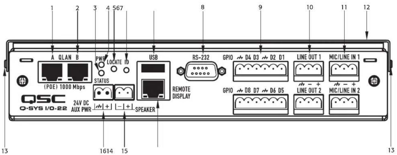
-
Figure 1 -
-
LAN Port A (Q-LAN Primary) PoE (RJ-45)
- LAN Port B (Q-LAN Redundant) PoE (RJ-45)
- Status LED
- Power LED
- Locate LED (Flashes when its associated ID button in the Q-Sys design is pressed)
- ID Button (When pressed, the associated ID button in the Q-Sys Design flashes)
-
USB 2.0 host port interfaces (type A) – auxiliary functions (for future use)
-
RS-232 Connector
- Two GPIO Connectors (6-Pin Euro-Style connector)
- Line Out 1 and 2 (3-Pin Euro-Style connector)
- Mic/Line In 1 and 2 (3-Pin Euro-Style connector)
- Quick-release Mounting Bracket
- Mounting Bracket Pin
- Remote Display Connector (RJ-45)
- Loudspeaker Output (2-Pin Euro-Style connector)
- 24 VDC Auxiliary Power Connector (2-Pin Female EuroStyle connector)
I/O-22 Side Panel Features
- Reset Button Access Slot
- Reset Button
- Mounting Bracket Locking Detent
- Mounting Bracket Pin
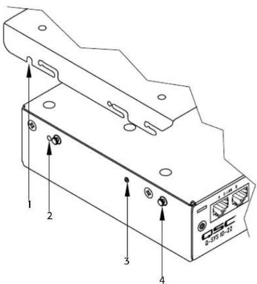
- Figure 2 -
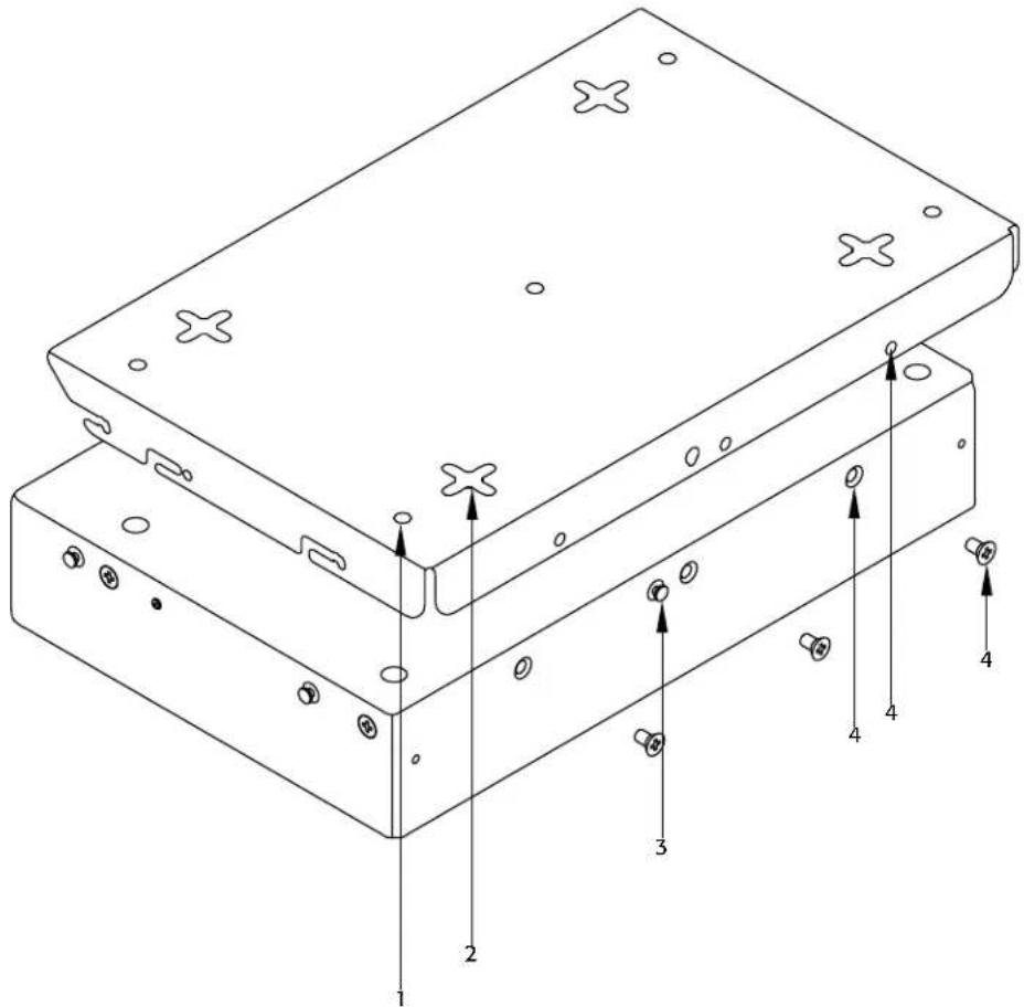
I/O-22 Rear Panel Features
-
Figure 3 -
-
Bracket Securing Holes – "Mounting Option 1" on page 9
-
Bracket Mounting Slots - "Mounting Option 2" on page 10
-
Rear Bracket Mounting Pin
- Bracket Securing Holes and Screws—“Mounting Option 2” on page 10
The Q-Sys Q-LAN Network
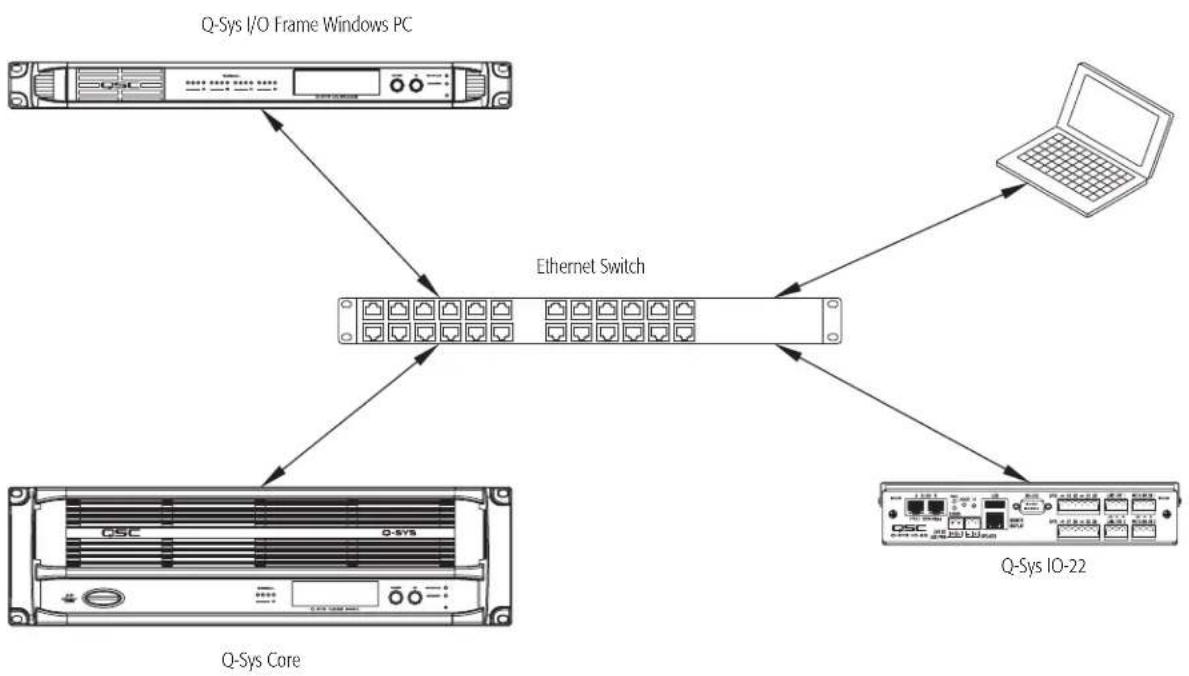
The Q-Sys solution (Figure 4) is designed to be deployed on QSC's high performance Q-LAN network. Q-LAN is a proprietary network implementation that bundles several industry standard protocols into a data transport solution appropriate for live performance multimedia environments. Q-LAN offers gigabit data rates, device and network redundancy, 32-bit floating point audio data transfers, and low-latency support on local area network deployments. Accurate synchronization of end nodes and high-quality clock distribution are built into the Q-LAN solution using the IEEE-1588 Precision Time Protocol. Discovery of end nodes and auto-configuration of end nodes are all included in the solution using industry standard protocols over a standards-based IP network implementation that utilizes off-the-shelf hardware components.
The figure below shows a very simple Q-LAN network implementation with a Q-Sys Core Processor, a Q-Sys I/O Frame, a Q-Sys I/O-22, Ethernet switch, and a PC running Q-Sys Designer.
All devices are connected to a managed 1000 Mbps Ethernet switch that includes the appropriate QoS (Quality of Service), suitable for a high-performance gigabit network to support multimedia applications.
The I/O-22 can be configured via Q-Sys Designer for one or two analog Mic/Line inputs, one or two analog Line outputs, redundant network, and GPIO functionality. All audio is processed by the Core Processor based on the Q-Sys design running on the Core..

ROTE: A PC is only required during initial configuration of the system or when a PC is the preferred means for providing on-going management services to the system designer or operator.
flowchart
graph TD
    A["Q-Sys I/O Frame Windows PC"] --> B["Ethernet Switch"]
    C["Q-Sys Core"] --> B
    D["Q-Sys IO-22"] --> B
    B --> E["Computer"]
-
Figure 4 -
-
The optional Q-Sys I/O Frame provides an audio access point for the Q-Sys system by providing the means to get audio onto and off of the Q-LAN network.
- The Q-Sys Core Processor provides signal processing, distribution, and management services for the Q-Sys system. All time-sensitive audio and management communications traverse the Q-LAN network. In addition, the Core provides an audio access point to get audio onto and off of the Q-LAN network.
- The Windows PC can be a desktop or laptop running Q-Sys Designer or Q-Sys UCI Viewer remote management application. The PC is only required by the Q-Sys system during the design phase for designing and configuring the system. The PC is not required for runtime operation, though it may be used for on-going system management
- The Q-Sys I/O-22, in conjunction with the Core Processor, provides dedicated audio inputs and outputs for the Q-Sys system.
Unpacking
There are no special unpacking precautions. However, it is recommended that you keep the original packing materials for reuse in the rare event that service is required. If service is required and the original packing material is not available, ensure that the unit is adequately protected for shipment (use a strong box of appropriate size with sufficient packing/padding material to prevent load shifting or impact damage), or call QSC's Technical Services Group for replacement packing material and a carton.
I/O-22 Packing List
- Q-Sys I/O-22
- 6-pin Euro-Style Connectors (green) for GPIO (2)
- Q-Sys I/O-22 Mounting Bracket
- 3-pin Euro-Style Connectors (green) for Line Out (2)
- Q-Sys I/O-22 Mounting Bracket Template
- 3-pin Euro-Style Connectors (orange) for Mic/Line In (2)
- Unit to Bracket Screws
- 2-pin Euro Connector (green) for Speaker Out (1)
- Hardware User Manual
- 2-pin inverted Euro-Style Connector (green) for Aux Power In (1)
- Mounting point standoff covers (2)
Mounting
The Q-Sys I/O-22 is designed to be mounted in a small area, in any orientation. In addition, you can use either of two mounting options as described below.
Mounting Option 1
Mounting Option 1 secures the Mounting Bracket to the mounting surface, then the I/O-22 unit is snapped into the bracket. You can easily remove the I/O-22 box from the Mounting Bracket, while the Mounting Bracket itself stays on the mounting surface.
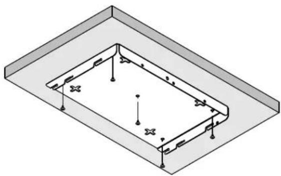
- Use the Mounting Bracket as a template, and mark the five screw holes (Figure 5) on the mounting surface.
- Using an appropriate size drill bit for the screws you are going to use, drill five holes in the mounting surface where you marked them in step 1.
- Use an appropriate screw driver and five screws to secure the Mounting Bracket to the mounting surface.
- Ensure that the screws are screwed in all the way to prevent damage, and allow enough clearance to install the I/O-22 unit.

ROTE: Depending on the available clearance for your installation, you may connect the cabling before or after attaching the I/O-22 to the Mounting Bracket.
Refer to Figure 6
- Carefully align the Mounting Pins (1) on the I/O-22 with the slots in the Mounting Bracket. Ensure both sides are aligned properly.
-
Push up on the I/O-22 until the Mounting Pins are at the top of the vertical portion of the slots.
-
Push back on the I/O-22 until the Mounting Pins are at the back of the horizontal portion of the slot, and the Mounting Bracket Locking Detent is engaged with the Detent Hole (2) on the Mounting Bracket.
-
Refer to "Connections" on page 11 for instructions on connecting the cables to the I/O-22.
natural_image
Isometric technical diagram of a rectangular structural frame with mounting holes and bolted joints (no text or symbols)- Figure 5 -
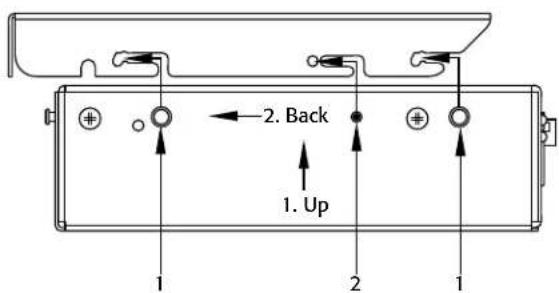
- Figure 6 -
Mounting Option 2
Mounting Option 2 secures the Mounting Bracket to the I/O-22, then the Mounting Bracket and I/O-22 are mounted to the mounting surface. You can easily remove the I/O-22 and Mounting Bracket assembly from the mounting surface.
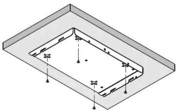
- Using the Mounting Bracket as a template, mark the four four-way screw slots (Figure 7) on the mounting surface.
- Using an appropriate size drill bit for the screws you are going to use, drill four holes in the mounting surface in the center of the four-way slots you marked in step 1.

ROTE: Ensure that the screws have a small enough head to fit through the center of the four-way slot, yet large enough not to fit through the slots.
-
Use an appropriate screw driver to install four screws into the mounting surface leaving enough room between the screw head and the mounting surface to allow for the thickness of the Mounting Bracket.
-
Prior to assembling the I/O-22 and Mounting Bracket, install the Mounting Bracket onto the mounting surface to test the fit of the screws and the four-way mounting slots. You should be able to install the bracket easily, and it should be snug enough against the mounting surface to prevent accidental movement. Make any needed adjustments to the screws before continuing.
-
Remove the Mounting Bracket from the mounting surface.
-
Refer to Figure 6 and complete steps 5 through 7 on page 9 to assemble the Mounting Bracket to the I/O-22.
-
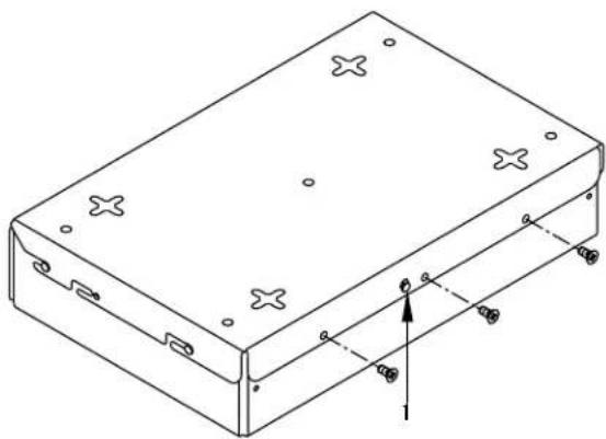
Install three screws (supplied) through the Mounting Bracket and into the IO-22 as shown in Figure 8. Tighten the screws.
natural_image
Isometric diagram of a rectangular frame with mounting holes and bolted joints, no text or symbols present- Figure 7 -
natural_image
Technical line drawing of a rectangular electronic enclosure with mounting holes and a central axis indicator (no text or symbols)- Figure 8 -

ROTE: Depending on the available clearance for your installation, you may connect the cabling before or after attaching the I/O-22 to the Mounting Bracket.
-
Mount the I/O-22 / Mounting Bracket assembly by aligning the four-way slots with the screws installed in step 3, pushing the assembly up against the mounting surface, then slide the unit in one of the four directions provided by the slots.
-
Ensure that the assembly is snug against the mounting surface.
-
Refer to "Connections" on page 11 for instructions on connecting the cables to the I/O-22.
Connections
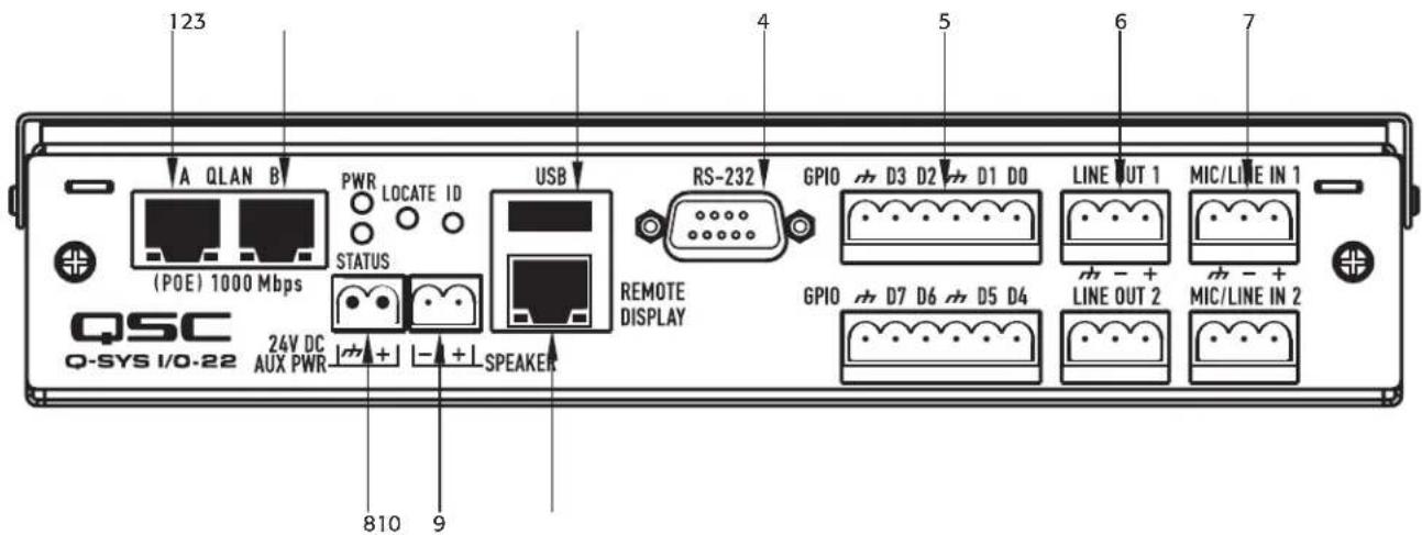
When making connections to the I/O-22, make sure that the cables are secured in such a was as to provide stress relief for all connectors you use.
-
Figure 9 -
-
Q-LAN A - PoE/PoE+ capable (RJ-45) - Required.
-
Provides the primary connection between the I/O-22 and the design running on the Q-Sys Core Processor via the Q-LAN network. For details on the Q-LAN network, and Q-Sys redundancy, refer to the Networking section of the Q-Sys Designer online help.
-
Provides the connection for PoE and PoE+ power, if available from the Ethernet switch.
-
Q-LAN B - PoE/PoE+ capable (RJ-45) - Optional.
-
Provides redundant network capability in the event of LAN-A failure.
-
Provides the connection for PoE and PoE+ power, if available from the Ethernet switch.
-
USB (2.0) host port interfaces (type A) – Optional
-
Provides auxiliary functions (for future use)
-
Current limited
-
RS-232 – The RS-232 connector is represented in Q-Sys Designer by the I/O-22 Serial Port component. When you connect a Q-Sys Control Script component to the I/O-22 Serial Port component, and write an appropriate Lua script, you can control and read from devices such as DVD players, recording hardware, video, lighting, and so on.
- GPIO (two 6-Pin Euro-Style connectors) – The GPIO controller is used to integrate Q-Sys with custom or third-party controls. Using the GPIO you can control external hardware and certain aspects of Q-Sys with external hardware. The GPIO provides digital input and output control signals and clock signals. The GPIO is configured in the Q-Sys design through the I/O-22 GPIO component. Refer to the I/O-22 GPIO component online help in Q-Sys Designer for details.
- LINE OUT 1 and 2 (3-Pin Euro-Style connector) – The output can be used as input for amplifiers, recording devices, and so on. Line Out 2 is the same line-level signal sent to the I/O-22 amplifier.
- MIC/LINE In 1 and 2 (3-Pin Euro-Style connector) – Can be used to connect a microphone (Phantom power available), or any line-level device.
- 24 VDC AUX PWR (2-Pin Female Euro-Style connector) – Optional, +24 VDC only.
- Speaker (2-Pin Euro-Style connector)
- Powered by a single-channel amplifier. The input for the amplifier is Channel 2 in Q-Sys Designer, and is the same signal supplied at LINE OUT 2.)
• Supports a 4 or 8 ohm loudspeaker
- Remote Display Connector (RJ-45) – for future use.
I/O-22 Dimensions
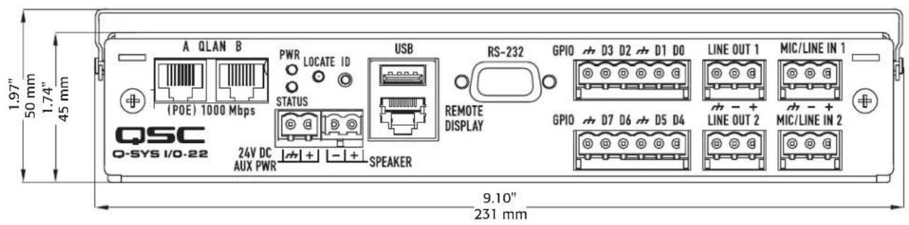
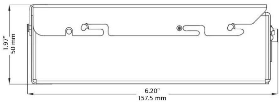
The dimensions for width and depth are the same with or without the bracket. The dimension for depth includes the RS-232 connector.
- Figure 10 -
I/O-22 Specifications
| Line Input | |
| Dynamic Range | ROTE: The Dynamic range depends on the "Peak Input Level" setting. |
| Unweighted At -27 to +12 setting, Dynamic range is >98 dB minimum, and >100 dB typicalAt -56 to -28 setting, Dynamic range is >83 dB minimum, and >88 dB typical | |
| A-weighted At -27 to +12 setting, Dynamic range is >101 dB minimum, and >103 dB typicalAt -56 to -28 setting, Dynamic range is >86 dB minimum, and >91 dB typical | |
| THD+N (Total Harmonic Distortion + Noise) (20 Hz - 20 kHz) at maximum input levels | |
| +12 dB gain setting -82 dB (0.0079%) maximum, -85 dB (0.0056%) typical | |
| -8 dB gain setting -74 dB (0.02%) maximum, -78 dB (0.012%) typical | |
| -28 dB gain setting -75 dB (0.02%) maximum, -78 dB (0.013%) typical | |
| Crosstalk (20 Hz - 20 kHz) -78 dB maximum, -80 dB typical | |
| Frequency Response (20 Hz - 20 kHz) +0 dB to -1 dB maximum, +0 dB to -0.8 dB typical | |
| Input Impedance | |
| Balanced 10K ohms | |
| Unbalanced 10K ohms | |
| Common Mode Rejection (20 Hz - 20 kHz) -62 dB maximum, -65 dB typical | |
| Maximum Input Level | ROTE: The Input level is continuously variable from -56 dB to +12 dB. Internally, there are switches that auto-select based on the Max RMS Input Level. The maximum input level to achieve 0 dBs at the A/D converter is shown below, all in-between settings use software attenuation. |
| Vrms 30.8 mV, 1.9 V, and 3.09 V | |
| dBu | -28 dB, -8 dB, and +12 dB |
| dBV | -30.2 dB, -5.8 dB, and 9.8 dB |
| Line Output | |
| Dynamic Range | |
| Unweighted >101 dB minimum, 104 dB typical | |
| A-weighted >104 dB minimum, 107 dB typical | |
| Channel to Channel Crosstalk (20 Hz - 20 kHz) | 102 dB maximum, -104 dB typical |
| Max Output Level | 10 dB, 7.8 dB, 2.5 V(Continuously adjustable from -10 dB to +10 dB) |
| Mute | Relay – infinite attenuation |
| Frequency Response (20 Hz to 20 kHz) | +0, -1 maximum, -0.6 typical |
| THD+N | -82 dB (0.079%) maximum, -85 dB (0.056%) typical |
| Loudspeaker | 4 or 8 ohms, 10 watts (not included) |
| Amplifier | ROTE: Output power is determined by the power source. Refer to the specifications in this table for Power Source |
| Frequency Response (20 Hz to 20 kHz) | +0 dB to -3 dB maximum, +0 dB to -2.5 dB typical |
| THD+N | |
| 4 ohms | -45 dB (0.56%) maximum, -47 dB (0.45%) typical |
| 8 ohms | -50 dB (0.32%) maximum, -52 dB (0.25%) typical |
I/O-22 Specifications
Controls and Indicators
| Status LED Green |
| Power LED Green |
| ID button When pressed, the associated ID button in the Q-Sys Design flashes |
| Locate LED Green Flashes when its associated ID button is pressed in the Q-Sys design |
Power Source
ROTE: You must use either the AUX PWR or PoE. In addition, you can use both AUX PWR and PoE.
AUX PWR External Supply (not included), +24 VDC, 30 watts minimum, 1.25 A
PoE PoE (IEEE 802.3.af) or PoE+ (IEEE 802.3at) via Q-LAN A, Q-LAN B or both.
| Power Configuration | Average Amplifier Power Output ^2 | Peak Amplifier Power Output ^2,3 |
| Single PoE | 2-3W @ 4Ω, 2-3W @ 8 Ω | 9W @ 4Ω, 4W @ 8Ω |
| Dual PoE ^i | 8-10W @ 4Ω, 4W @ 8 Ω | 9W @ 4Ω, 4W @ 8Ω |
| Single PoE+ | 8-10W @ 4Ω, 4W @ 8 Ω | 9W @ 4Ω, 4W @ 8Ω |
| Dual PoE+ | 8-10W @ 4Ω, 4W @ 8 Ω | 9W @ 4Ω, 4W @ 8Ω |
| AUX PWR | 8-10W @ 4Ω, 4W @ 8 Ω | 9W @ 4Ω, 4W @ 8Ω |
^2 Dual PoE or PoE and PoE+
^2 Peak power, as measured over an approximately 10 second interval.
^3 Numbers are typical output power.
Connectors
| LAN Port A (Q-LAN Primary) PoE | RJ-45 |
| LAN Port B (Q-LAN Redundant) PoE | RJ-45 |
| Auxiliary functions (for future use) | USB 2.0 host port interfaces (type A) |
| Third-party control interface | RS-232 |
| Two GPIO Connectors | 6-Pin Euro-Style connector |
| Line Out 1 and 2 | 3-Pin Euro-Style connector |
| Mic/Line In 1 and 2 | 3-Pin Euro-Style connector |
| Remote Display Connector (for future use) | RJ-45 |
| Loudspeaker Output | 2-Pin Euro-Style connector |
| 24 VDC Auxiliary Power Connector | 2-Pin Female Euro-Style connector |
Dimensions (HWD)
| I/O-22 (without bracket) 1.74" x 9.10" x 6.20" (45.0 mm x 231.0 mm x 157.5 mm) | |
| I/O-22 (with bracket) | 1.97" x 9.10" x 6.20" (50.0 mm x 231.0 mm x 157.5 mm) |
Weight
| I/O-22 (without bracket) 3.0 lbs (1.4 kg) |
Bracket
0.5 lbs (0.2 kg)
QSC™
Contact
Mailing Address
QSC Audio Products, LLC
1675 MacArthur Boulevard
Costa Mesa, CA 92626-1468 U.S.
Main Number
(714) 754-6175
World Wide Web
www.qscaudio.com
Sales & Marketing
Voice
(714) 957-7100 International
Toll free (U.S. only) (800) 854-4079
FAX
(714) 754-6174
info@qscaudio.com
Support
24/7 Support
QSC offers 24/7 support on Q-Sys™
Networked Audio Systems only.
Full Support
Business Hours: 6 AM to 5 PM Pacific Time (Mon-Fri)
Tel. 800-772-2834 (U.S. only)
Tel. +1 (714) 957-7150
Fax. +1 (714) 754-6173
Q-Sys Emergency-only After-Hours and Weekend Support*
Tel: +1-888-252-4836 (U.S./Canada)
Tel: +1-949-791-7722 (non-U.S.)
* After hours calls are guaranteed a 30 minute response time from a Q-Sys Support Team member for Q-Sys ONLY!
qsyssupport@qscaudio.com
(immediate e-mail response not guaranteed. For URGENT issues use the phone numbers above.)
Q-Sys™ Customer Support
- EXPLANATION OF TERMS AND SYMBOLS
- IMPORTANT SAFETY INSTRUCTIONS
- FCC Statement
- Warranty (USA only; other countries, see your dealer or distributor)
- QSC Audio Products 3 Year Limited Warranty
- RoHS STATEMENT
- Introduction
- I/O-22 Features
- I/O-22 Side Panel Features
- I/O-22 Rear Panel Features
- The Q-Sys Q-LAN Network
- Unpacking
- I/O-22 Packing List
- Mounting
- Mounting Option 1
- Mounting Option 2
- Connections
- I/O-22 Dimensions
- I/O-22 Specifications
- QSC™
- Contact
- Sales & Marketing
- Support
Brand : QSC
Model : I/O-22
Category : Soundcard