
Attero Tech unDNEMO - Uncategorized QSC - Free user manual and instructions
Find the device manual for free Attero Tech unDNEMO QSC in PDF.


| Product Type | Dante Network Audio Monitor |
| Brand | QSC (Attero Tech) |
| Model | unDNEMO |
| Dimensions (W x H x D) | 6.45 x 2.6 x 6.23 in (164 x 66 x 158 mm) |
| Weight | 1.13 lb (0.51 kg) |
| Power Supply | PoE 802.3af (IEEE 802.3af compliant) or 24V DC (center positive, 6.0mm OD / 2.0mm ID) |
| Power Consumption | < 6 W max |
| Audio Inputs | Internal electret microphone, external electret headset mic (3.5mm T-S), line input (3.5mm TRS, 10kΩ impedance, +12dBu max) |
| Audio Outputs | Internal 1" speaker (1W max), stereo headphone output (3.5mm TRS, 1Vrms into 32Ω) |
| Network Interfaces | Dual RJ-45 (left port supports PoE), 1000 Mbps, Dante/AES67 |
| Sample Rate | 48 kHz |
| Minimum Dante Latency | 1 ms |
| Display | OLED display with adjustable brightness |
| Controls | Backlit keypad: speaker mute, mic mute, menu, CH up/down, source select, volume +/- |
| Mounting | Desk placement with non-slip pad or keyhole mounting for #6 screws (max screw depth 6.0mm) |
| Operating Temperature | 0 to 40°C (32 to 104°F) |
| Compliance | FCC Part 15 Class A, CE EN55022 Class A, RoHS, REACH |
| Included Accessories | USB Mini B to USB A 6 ft cable |
| Optional Accessories | 24V DC power supply (P/N 900-00175) |
| Maintenance | Clean only with a dry cloth |
| Safety Precautions | Do not expose to rain or moisture; use only specified attachments; refer servicing to qualified personnel |
| Warranty | Refer to QSC Limited Warranty at www.qsc.com |
Frequently Asked Questions - Attero Tech unDNEMO QSC
User questions about Attero Tech unDNEMO QSC
0 question about this device. Answer the ones you know or ask your own.
Ask a new question about this device
Download the instructions for your Uncategorized in PDF format for free! Find your manual Attero Tech unDNEMO - QSC and take your electronic device back in hand. On this page are published all the documents necessary for the use of your device. Attero Tech unDNEMO by QSC.
USER MANUAL Attero Tech unDNEMO QSC
unDNEMO
Dante™/AES67 Network Audio Interface
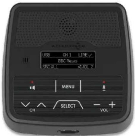
User Manual
Date 2/21/2020
1675 MacArthur Boulevard · Costa Mesa, CA 92626
Ph: 800/854-4079 or 714/957-7100 · Fax: 714/754-6174
© 2020 QSC, LLC all rights reserved. QSC and the QSC logo are registered trademarks of QSC, LLC in the U.S. Patent and Trademark office and other countries. All other trademarks are the property of their respective owners. Patents may apply or be pending.
www.qsc.com
614-00030
IMPORTANT SAFETY INSTRUCTIONS
The symbols below are internationally accepted symbols that warn of potential hazards with electrical products.


This symbol, wherever it appears, alerts you to the presence of un-insulated dangerous voltage inside the enclosure -- voltage that may be sufficient to constitute a risk of shock.
This symbol, wherever it appears, alerts you to important operating and maintenance instructions in the accompanying literature. Please read the manual.
-
Read these instructions.
-
Keep these instructions.
-
Heed all warnings.
-
Follow all instructions.
-
Do not use this apparatus near water.
-
Clean only with a dry cloth.
-
Do not block any ventilation openings. Install in accordance with the manufacturer's instructions.
-
Do not install near any heat sources such as radiators, heat registers, stoves, or other apparatus (including amplifiers) that produce heat.
-
Do not defeat the safety purpose of the polarized or grounding-type plug. A polarized plug has two blades with one wider than the other. A grounding type plug has two blades and third grounding prong. The wider blade or the third prong is provided for your safety. If the provided plug does not fit into your outlet, consult an electrician for replacement of the obsolete outlet.
-
Protect the power cord from being walked on or pinched particularly at plugs, convenience receptacles, and the point where they exit from the apparatus.
-
Only use attachments/accessories specified by Attero Tech
-
Use only with the cart, stand, tripod, bracket, or table specified by the manufacturer, or sold with the apparatus.
-
When a cart is used, use caution when moving the cart/apparatus combination to avoid injury from tip-over.
-
Unplug this apparatus during lightning storms or when unused for long periods of time.
-
Refer all servicing to qualified service personnel. Servicing is required when the apparatus has been damaged in any way, such as power-supply cord or plug is damaged, liquid has been spilled or objects have fallen into the apparatus, the apparatus has been exposed to rain or moisture, does not operate normally, or has been dropped.
-
This apparatus shall be connected to a mains socket outlet with a protective earthing connection.
-
When permanently connected, on all-pole mains switch with a contact separation of at least 3mm in each pole shall be incorporated in the electrical installation of the building.
-
If rack mounting, provide adequate ventilation. Equipment may be located above or below this apparatus but some equipment (like large power amplifiers) may cause an unacceptable amount of hum of may generate too much heat and degrade the performance of this apparatus,
-
This apparatus may be installed in a industry standard equipment rack. Use screws through all mounting holes to provide the best support.

TO REDUCE THE RISK OF FIRE OR ELECTRIC SHOCK, DO NOT EXPOSE THIS APPARATUS TO RAIN OR MOISTURE.
WARRANTY INFORMATION
For a copy of the QSC Limited Warranty, visit the QSC website at www.qsc.com
Note: This equipment has been tested and found to comply with the limits for a Class A digital device, pursuant to Part 15 of the FCC Rules and EN55022. These limits are designed to provide reasonable protection against harmful interference when the equipment is operated in a commercial environment. This equipment generates, uses and can radiate radio frequency energy and, if not installed and used in accordance with the instruction manual, may cause harmful interference to radio communications. Operation of this equipment in a residential area is likely to cause harmful interference, in which case the user will be required to correct the interference at their own expense.


This symbol means the product must not be discarded as household waste, and should be delivered to an appropriate collection facility for recycling. Proper disposal and recycling helps protect natural resources, human health and the environment. For more information on disposal and recycling of this product, contact your local municipality, disposal service, or the business where you bought this product.
Contents
1 - Overview....5
1.1 - What's in the Box? 5
1.2 - Optional Extras....5
1.3 - Product Features 6
2 - User Operation 8
2.1 - User Interface Description 8
2.1.1 - Display Layout 8
2.1.2 - Keypad Layout 8
2.2 - Audio Mode Navigation....9
2.2.1 - Net Mode 9
2.2.2 - USB Mode....9
2.2.3 - Line Input Mode 10
2.2.4 - All Input Mode 10
2.3 - Menu Mode Navigation .....11
2.3.1 - Menu Mode: Brightness Control....12
2.3.2 - Menu Mode: Device Info 12
3 - System Setup....13
3.1 - Single Port Mode 13
3.2 - Daisy Chain Deployment ....13
3.3 - PoE Deployment ....15
3.4 - Dante Configuration Notes....16
3.5 - Factory Reset....16
4 - Mechanical Information 17
4.1 - Mounting Information ....17
5 - ARCHITECTS & ENGINEERS SPECIFICATION 18
5.1 - Device Specifications .... 19
APPENDIX A - Reference Documents....A-1
1 - Overview
The unDNEMO is a highly flexible Dante™ network audio monitoring solution that can be deployed in a wide array of pro-AV applications. The unDNEMO is capable of monitoring one audio channel selected from up to 64 configured Dante™ network audio channels that are available on the network from Dante enabled audio equipment from any manufacturer. Audio selection is done with simple front panel controls. The unDNEMO utilizes Attero Tech's unIFY Control Panel v2.0 or later software for simple setup and configuration.
In addition to the flexible Dante® audio monitoring functionality, the unDNEMO is aimed at comprehensive audio monitoring applications and supports the following features:
User selectable reception of one of up to 64 Dante™ audio channels
- Internal monitoring speaker
Internal microphone with optional external mic input, allowing for talkback communications or for soft-conferencing applications in conjunction with the USB audio interface - Easy access front panel headset (headphone and mic connections) on 3.5mm connectors
Volume, channel, mic mute, speaker mute, and source select buttons - Easy-to-read OLED display for presentation of channel names, volume settings and configuration
Full duplex USB audio for PC audio content and soft-conferencing applications
PoE powered to work with any external +24VDC supply or compliant 802.3af PoE network switch or mid-span injector
Dante Daisy Chaining allows multiple unDNEMO devices, as well as other Attero Tech daisy chain enabled devices, to be connected over a single home-run to an Ethernet switch
1.1 - What's in the Box?
The unDNEMO comes supplied with the following
(1) unDNEMO device
○ (1) USB Mini B to USB A 6ft cable
1.2 - Optional Extras
The following are available as options for the unDNEMO and that may be ordered separately:
24V DC Power Supply - P/N: 900-00175
1.3 - Product Features
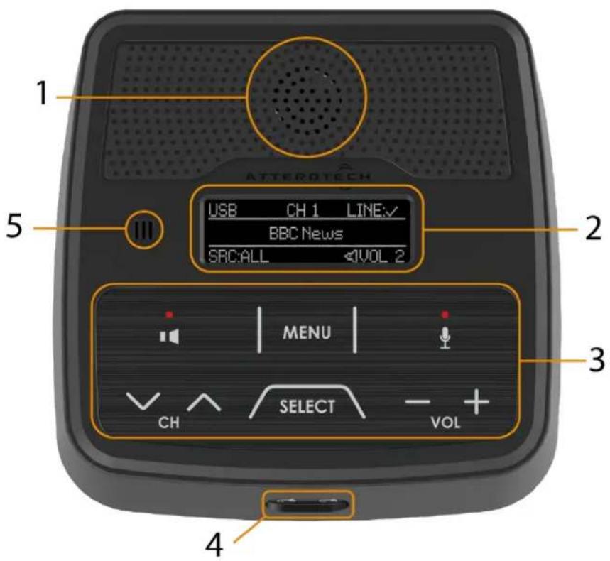
| 6 | 3.5m TRS Stereo Line Input |
| 7 | 2x2 USB Audio interface on USB-mini B |
| 8 | Recessed Factory Reset switch |
| 9 | Daisy Chain Dante Ethernet ports (Left port supports 802.3af PoE) |
| 10 | 24V DC Power Input |
2 - User Operation
The unDNEMO features a number of different modes and capabilities. The unDNEMO supports the following audio modes: - Net Mode - USB Mode - Line Input Mode - All Input Mode All of these audio modes except the Net Mode can be enabled or disabled for the intended application using the unIFY Control Panel Software. For detailed software configuration instructions, consult with the integrated Help documentation included with the software.2.1 - User Interface Description
2.1.1 - Display Layout
 Figure 3 - Display Layout The unDNEMO features a high visibility OLED display for high visibility in varying ambient light conditions. The display screens are organized into a title bar, main active content area and a status bar. The status bar always indicates the active audio source mode and the current volume settings.2.1.2 - Keypad Layout
 Figure 4 - Keypad Layout The keypad controls consist of the following buttons: - Output Mute - Menu - Mic Mute - Channel/Nav Down - Channel/Nav Up - Source Select • Volume Down • Volume Up The mute buttons always function to mute their respective audio functions. Additionally, the "Menu" button is always used to toggle between Menu and Audio modes. The remaining buttons are multi-function based on the active mode and will be further explained in the detailed descriptions of each audio and menu mode. The unDNEMO features a configurable inactivity timeout, when this timeout expires the display will go dark, but the keypad will remain at the programmed brightness setting.2.2 - Audio Mode Navigation
The user may cycle through the available audio modes by pressing the "Select" button to toggle through the available modes. flowchart
graph LR
    A["Net Mode"] --> B["USB Mode"]
    B --> C["Line Mode"]
    C --> D["All Input Mode"]
    D -->|Feedback| A
2.2.1 - Net Mode
The primary operating mode for audio monitoring is the Net Mode. In this mode Dante audio channels may be selected by the user from the front panel controls for simple and efficient audio monitoring applications. When in this mode the display will indicate the channel number that has been assigned using the unIFY Control Panel Software in the top area of the display and the configured channel name for the selected channel in the central viewing area of the displayed.  Figure 8 - Brightness Control If Dante TX audio features are enabled within the unIFY Control Panel software for the unDNEMO, the line input audio will also be routed to the first and second Dante audio transmit channels of the device for audio bridging applications. Dante Controller or another 3 ^rd party application must be used to route the audio to the intended Dante receive device.2.2.4 - All Input Mode
The all input mode allows the user to simultaneously monitor a mix of the audio from the selected Dante network audio channel, the line level analog input and the USB audio input. This is useful in applications that require monitoring audio from multiple, independent sources simultaneously.  Figure 10 - All Input Mode Audio Routing In the All input mode, the USB, and Line input sources are indicated with a checkmark on the title bar of the display when they are connected. The main content area of the screen shows the channel name of the network input audio, with the active channel number shown in the center of the title bar. The channel Up/Down buttons are used to navigate the network audio channel selection just as they operate in the Net Mode. The All Input mode does not support any Dante TX audio routing capabilities.2.3 - Menu Mode Navigation
The unDNEMO features a number of menu screens for showing status and basic device configuration. The menu mode access is also a configurable option that can be disabled for applications where the end user may only require limited access to the devices features. By default, the menu mode access is disabled and must first be enabled from the configuration software. Once enabled, the menu mode may be entered by pressing the "Menu" button. While in menu mode, the display will indicate MENU: in the upper left of the screen. To exit menu mode, press the MENU button again to toggle back to the audio modes. The following diagram depicts the menu navigation. Use the Up and Down channel buttons to cycle between the Display Brightness and Device Info menus. Use the "+" and "-" buttons to adjust the value or navigate the sub-menus for each menu mode screen. flowchart
graph TD
    A["Display Menu: Brightness Control"] --> B["Device Info: Device Name"]
    B --> C["Device Info: FW Versions"]
    C --> D["Device Info: MAC Address"]
    D --> E["Device Info: IP Address"]
    E --> B
2.3.1 - Menu Mode: Brightness Control
The brightness control menu allows the user to adjust the brightness level of the display and the keypad LED backlight brightness by adjusting the level with the "+" and "-" buttons respectively.2.3.2 - Menu Mode: Device Info
The device info menus allow the user to view information about the device including the Dante device name that is advertised on the Dante network, the FW version information, the device MAC address and the current device IP address. To navigate between the Device Info menu screen content, use the "+" and "-" buttons respectively. The FW versions screen shows the version information for both the device application processor (shown as FW:) and the Dante product version (shown as D:). The MAC address screen shows the device MAC address and can also be identified by referencing the label placed on the bottom of the unit. The IP address screen shows the current IP address of the device. To change the IP address settings, use Dante Controller or other configuration software that supports general networking configuration for Dante devices.  Figure 12 - Brightness Control  Figure 16 - Device Info: IP3 - System Setup
\*Note: All Attero Tech products are tested using UTP cabling and it is recommended that UTP cabling be used when installing them. STP cabling can be used for installation though care must be taken not introduce grounding issues into the system by doing so.3.1 - Single Port Mode
The unDNEMO is configured for single port mode by default. In this mode the second, non-PoE powered Ethernet port is disabled to provide security for applications that require restricted access to the network. For a device that has been altered from its factory defaults, single port mode may be re-enabled via Dante Controller. Select "Single Port" from the Network Config tab within the Device View window. This will require a reboot of the device.3.2 - Daisy Chain Deployment
The unDNEMO can be deployed in standard Ethernet networks with and without external switching hardware. To enable this switched mode, select "Dual Port - Switched" from the Network Config tab within the Device View window. This will require a reboot of the device. The first example below shows the Dante port of an audio DSP connected to the Ethernet (Dante) port of the unDNEMO at supervisor station 1. Due to the integrated Gigabit Ethernet switch, other unDNEMO devices can be daisy-chained together to eliminate the need for any external Ethernet switches. \*Note: Each unDNEMO would require a local 24V DC power supply connection. Daisy chain of PoE is not possible. flowchart
graph TD
    A["Central Device"] --> B["Dante Audio"]
    B --> C1["Supervisor Station 1"]
    B --> C2["Supervisor Station 2"]
    B --> C3["Supervisor Station 3"]
    B --> C4["Supervisor Station 4"]
    B --> C5["Supervisor Station 5"]
    B --> C6["Supervisor Station 6"]
    B --> C7["Supervisor Station 7"]
    B --> C8["Supervisor Station 8"]
    C1 --> D1["Video Source 1 Audio Outputs"]
    C2 --> D2["Video Source 2 Audio Outputs"]
    C3 --> D3["Video Source 2 Audio Outputs"]
    C4 --> D4["Paging System"]
    C5 --> D5["Analog Audio Output To DSP"]
    C6 --> D6["Analog Audio Output To DSP"]
    C7 --> D7["Analog Audio Output To DSP"]
    C8 --> D8["Analog Audio Output To DSP"]
3.3 - PoE Deployment
The unDNEMO supports PoE 802.3af power on the left-most Ethernet port labeled "PoE+Data" on the rear panel of the unit. To utilize PoE, connect CAT-5e or better cabling between the PoE port of the unDNEMO and an 802.3af compliant PoE Ethernet switch or midspan power injector. In this configuration, PoE cannot be daisy-chained and each device requires a CAT-5 connection back to the Ethernet switch. The following diagram shows the unDNEMO devices used with an Ethernet switch providing both PoE and Dante connections, with audio sourced from an Attero Tech unD4I 4-channel analog input to Dante interface. flowchart
graph TD
    A["ATTERTECH"] -->|Audio Source 1| B["EDdunfe"]
    A -->|Audio Source 2| B
    A -->|Audio Source 3| B
    A -->|Audio Source 4| B
    B --> C["Darta Audio /PoE"]
    C --> D["Supervisor Station 1"]
    C --> E["Supervisor Station 2"]
    C --> F["Supervisor Station 3"]
    C --> G["Supervisor Station 4"]
    C --> H["Supervisor Station 5"]
    C --> I["Supervisor Station 6"]
    C --> J["Supervisor Station 7"]
    C --> K["Supervisor Station 8"]
    D --> L["Darta Audio /PoE"]
    E --> L
    F --> L
    G --> L
    H --> L
    I --> L
    J --> L
    K --> L
3.4 - Dante Configuration Notes
In general, there is little to no additional configuration required to successfully utilize the unDNEMO devices in a Dante network other than the initial channel configuration and setup required using the unIFY Control Panel software. However, if the unDNEMO is utilized in a Dante network with audio transmit channels that are already configured to transmit to one or more Dante receive devices, the potential exists that the unDNEMO will not be able to subscribe to the Dante transmitter as the number of unicast receivers assigned to transmitting device and channel may be exceeded. To mitigate this issue, the desired audio channels may be placed in multicast flows such that there is no limit on the number of Dante receive devices. In systems where a large number of unDNEMO devices are utilized, this is the recommended practice to mitigate these channel subscription limitations that exist when only using unicast Dante a audio transmission. Care should always be taken to understand how much multicast bandwidth exists on the Dante network, and utilize the tools within Dante Controller to identify any networking and Dante configuration issues.3.5- Factory Reset
The unDNEMO and unDNEMO-BT have a factory reset option. Using it will reset all the devices parameters back to their factory defaults including all the Dante® settings such as device name, channel names as well as the device settings such as input select. The devices IP address mode is also reset back to getting a dynamic IP. Access to the factory reset button is through a small circular hole on the rear of the unit between the USB and PoE Ethernet connector. To use the factory reset, insert a small screwdriver or paperclip into the hole to activate the factory reset switch. There should be a noticeable "click" when it's activated. Hold the switch in for approximately 10 seconds then release. If the factory reset was successful, a few seconds after releasing the switch, the unit will reset itself.4- Mechanical Information
 Figure 19 - Top View Dimensions  Figure 20 - Bottom View Dimensions  Figure 22 - Front View Dimensions  Figure 21 - Side View Dimensions4.1 - Mounting Information
The unDNEMO is designed to be placed on a smooth surface and features a non-slip pad on the base of the unit. For mounting on non-horizontal surfaces, the base of the unit features two keyhole openings for mounting that accept a #6 size screw head. Care should be taken not to insert the screw head deeper than 6.00mm from the base of the unit.5 - ARCHITECTS & ENGINEERS SPECIFICATION
The Dante network monitor shall be able to monitor any one of up to 64 Dante audio flows, and provide user selection of both channel and volume. The unit shall include a speaker and a headphone jack for reproduction of the Dante audio. The unit shall provide bi-directional USB 1.1 audio connectivity, and install without additional drivers on both Windows and Mac PCs. The unit shall provide one mic level and one line-level analog input, each on a 3.5mm connector. The unit shall be able to receive power from either the rear panel Dante interface over the Ethernet cable from a compliant 802.3af PoE network device or an external +24VDC power supply. A second rear panel Dante interface shall provide for daisy chain of the Dante network. The Dante interface shall be compliant with the RoHS, REACH and WEEE directives. The Dante interface unit shall be compliant with the EMI/EMC requirements for FCC (Part 15 Class A) and CE (EN 55022 Class) A. The Dante interface shall be the Attero Tech unDNEMO. 5.1 - Device Specifications| Audio Inputs | |
| Input Types: | Internal electret microphoneExternal electret headset microphone connectivity with internal bias (3.5mm T-S)Line Input: 3.5mm TRS |
| Input Impedance: | Line Input: 10kOhm |
| Maximum Input Levels: | Line Input: +12dBu |
| Mic Bias Voltage: | 1.65V |
| Audio Input Performance | |
| THD+N: | Line Input: <0.02% @ 1kHz |
| Frequency Response: | Line Input: 20Hz - 20kHz, +/- 1dB |
| Audio Outputs | |
| Speaker Type: | Internal 1" Driver |
| Attenuation Range | Software controlled volume(1 to 10(max), 6dB per step) |
| Headphone Output | Stereo 3.5mm TRS |
| MaximumOutput Levels: | Speaker: 1W @ max volumeHeadphone: 1Vrms into 32 Ohms (minimum load) |
| Audio Output Performance | |
| THD+N: | <0.01% @ 1kHz, input signal 3dB below maximum |
| Frequency Response | Headphone: 20Hz - 20kHz +/- 1dB |
| Dante Network | |
| Physical Level: | Ethernet |
| Connector(s): | Dual RJ-45 |
| Cable Quality: | CAT-5e or better |
| Transmission Speed: | 1000 Mbps |
| Supported Sample Rates | 48kHz |
| Minimum Dante Network Latency | 1 ms |
| Power Requirements | |
| PoE | 802.3af PoE PD compliant |
| External Power | 24V DC, center positive barrel jack, 6.0mm OD / 2.0mm ID |
| Power Consumption | < 6W Max |
| Cable Quality: | CAT-5e or better |
| Product Compliance | |
| FCC CFR 47 Parts 15BICES-003CE (EN55022)RoHSREACH | |
| Physical Dimensions | |
| Width | 6.45" |
| Height | 2.6" |
| Depth | 6.23" |
| Weight | 1.13 lbs |
| Environmental Specifications | |
| Operating Temperature | 0 to 40 C |
APPENDIX A - Reference Documents
The following table lists the relevant reference documents.| Document Title | Revision |
| Document title: | unDNEMO |
| Document file name: | unDNEMO_User_Manual.docx |
| Revision number: | <03> |
| Issued by: | Attero Tech |
| Issue Date: | 4/19 |
| Status: | Released |
| Revision | Date | Author | Description of change |
| 00_a | 6/17/16 | JDA | Initial Draft |
| 00_b | 6/22/16 | CNL | Review and reformat |
| 00_c | 6/23/16 | JDA | Cleaned up specs, comments |
| 00_d | 07/01/16 | CNL | Removed RoHS table |
| 01 | 07/01/16 | CNL | Release Version |
| 02 | 08/09/16 | TMS | Max Input Level on 3.5mm TRS input changed from +12dBu to +11dBu |
| 02_a | 10/16/17 | CNL | Bug #3485 – Update manual regarding UTP/STP cable |
| 02_b | 3/14/18 | SGG | Warranty Update/Factory Reset Procedure |
- unDNEMO
- Dante™/AES67 Network Audio Interface
- User Manual
- IMPORTANT SAFETY INSTRUCTIONS
- WARRANTY INFORMATION
- Contents
- - Overview....5
- - User Operation 8
- - System Setup....13
- - Mechanical Information 17
- - ARCHITECTS & ENGINEERS SPECIFICATION 18
- - Overview
- - What's in the Box?
- - Optional Extras
- - Product Features
- - User Operation
- - User Interface Description
- - Display Layout
- - Keypad Layout
- - Audio Mode Navigation
- - Net Mode
- - USB Mode
- - Line Input Mode
- - All Input Mode
- - Menu Mode Navigation
- - Menu Mode: Brightness Control
- - Menu Mode: Device Info
- - System Setup
- - Single Port Mode
- - Daisy Chain Deployment
- - PoE Deployment
- - Dante Configuration Notes
- 3.5- Factory Reset
- 4- Mechanical Information
- - Mounting Information
- - ARCHITECTS & ENGINEERS SPECIFICATION
- APPENDIX A - Reference Documents
Brand : QSC
Model : Attero Tech unDNEMO
Category : Uncategorized