PQDSA - Switch LG - Free user manual and instructions
Find the device manual for free PQDSA LG in PDF.

| Product Type | Switch |
| Brand | LG |
| Model | PQDSA |
| Dimensions (W x H x D) | 80 x 80 x 10 mm |
| Weight | 50 g |
| Rated Voltage | 220-240 V AC |
| Rated Current | 10 A |
| Frequency | 50/60 Hz |
| Function | ON/OFF switch with LED indicator |
| Material | Flame-resistant plastic |
| Color | White |
| Ingress Protection | IP20 |
| Operating Temperature | -10°C to 40°C |
| Humidity | Up to 95% non-condensing |
| Certifications | CE, RoHS |
| Warranty | 2 years |
| Cleaning | Wipe with a dry cloth |
| Installation | Wall-mount, requires minimum 60 mm depth box |
| Compatibility | Standard wall boxes, suitable for most lighting circuits |
| Standby Power Consumption | < 0.5 W |
Frequently Asked Questions - PQDSA LG
User questions about PQDSA LG
0 question about this device. Answer the ones you know or ask your own.
Ask a new question about this device
Download the instructions for your Switch in PDF format for free! Find your manual PQDSA - LG and take your electronic device back in hand. On this page are published all the documents necessary for the use of your device. PQDSA by LG.
USER MANUAL PQDSA LG
- Please read this installation manual completely before installing the product.
• Installation work must be performed in accordance with the national wiring standards by authorized personnel only. - Please retain this installation manual for future reference after reading it thoroughly.
Dry Contact Unit Installation Manual
TABLE OF CONTENTS
■Safety Precautions 3\~4
■Overview 5
■Part Description 7
■Installation Guide 9
■Step 1 9
■Step 2 ....10
■Administrator Guide 11
Safety Precautions
To prevent injury to the user or other people and property damage, the following instructions must be followed.
■ Incorrect operation due to ignoring instruction will cause harm or damage. The seriousness is classified by the following indications.

WARNING
This symbol indicates the possibility of death or serious injury.

CAUTION
This symbol indicates the possibility of injury or damage.
■Meanings of symbols used in this manual are as shown below.


Be sure not to do.
Be sure to follow the instruction.

WARNING
Installation
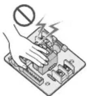
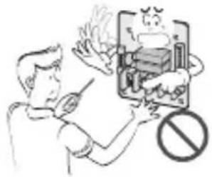
Don't touch with the hands while the power is on
- There is risk of fire or electric shock.
Use standard parts(connector).
- Do not disassemble or repair the product. There is risk of fire or electric shock.
For electrical work, contact the dealer, seller, a qualified electrician, or an Authorized Service Center.
- Do not disassemble or repair the product. There is risk of fire or electric shock.
natural_image
Illustration of a hand pressing a circuit board with a prohibition symbol (no text or labels)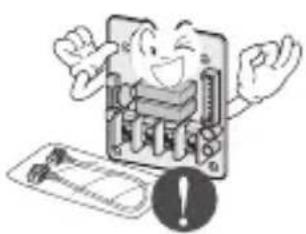
natural_image
Cartoon illustration of a smiling computer with an exclamation mark (no text or symbols)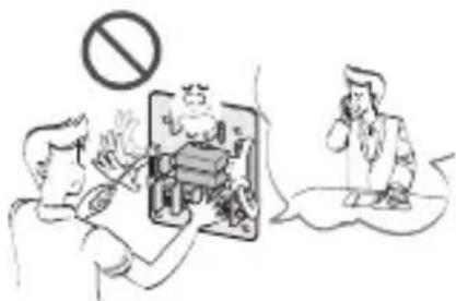
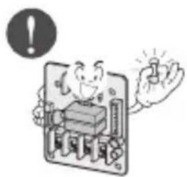
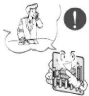
Use the correctly rated breaker or fuse.
- There is risk of fire or electric shock.
natural_image
Cartoon illustration of a smiling computer with an exclamation mark and a hand holding a button (no text or symbols)Do not install, remove, or re-install the unit by yourself (customer).
• There is risk of fire, electric shock, explosion, or injury.
For installation, always contact the dealer or an Authorized Service Center.
• There is risk of fire, electric shock, explosion, or injury.
natural_image
Illustration of a person in thought bubble and a computer screen with people (no text or symbols)Operation
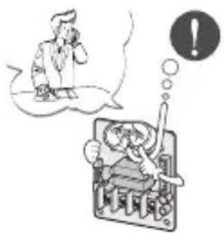
When the product is soaked (flooded or submerged), contact an Authorized Service Center.
• There is risk of fire or electric shock.
natural_image
Illustration of a person in thought bubble and a computer screen with a warning symbol (no text or labels)Be cautious that water could not enter the product.
- There is risk of fire, electric shock, or product damage.
natural_image
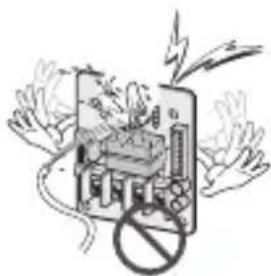
Illustration of a smartphone with a device emitting exhaust smoke, surrounded by hands holding a prohibition symbol (no text or labels)Overview
LG Dry Contact is a solution for automatic control of air conditioning system at the owner's behest.
In simple words, it's a switch which can be used to turn the unit On/Off after getting the signal from external sources like key-in lock, door or window switch etc specially used in Hotel rooms.
It's a small PCB that either can be fit inside the control box of Indoor unit or can be outside the unit in a plastic case if there is no sufficient space inside the Indoor unit.
Apart from simple installation, it can also be linked to Central Controller via Indoor unit PI485 pcb. For this, all connecting wires & an additional small pcb for looping is also provided along with Dry Contact.
Dry Contact can be used in two ways.
-
It can be used to actually turn On/Off the system on receiving the signal from the source. In this case, user doesn't need to use remote controller anymore to turn On/Off the system. However all the further settings like temperature, fan speed, mode etc can be done through remote controller only.
-
Other way is almost similar as above but in this case, after getting the On signal from the external source, user has to turn On the system from remote controller only. Dry contact just activates the system. However system can be turned Off directly from the external source. So only On mode is different here.
So in both of above conditions, system can't be operated without signal from external source which prevents unnecessary use of system & facilitates its operation only when its required.
These settings can be selected from the remote controller whose details have been explained in the later part of this manual
So depending upon the requirement, Dry Contact offers a variety of applications to suit the customer's requirement in the best possible way.
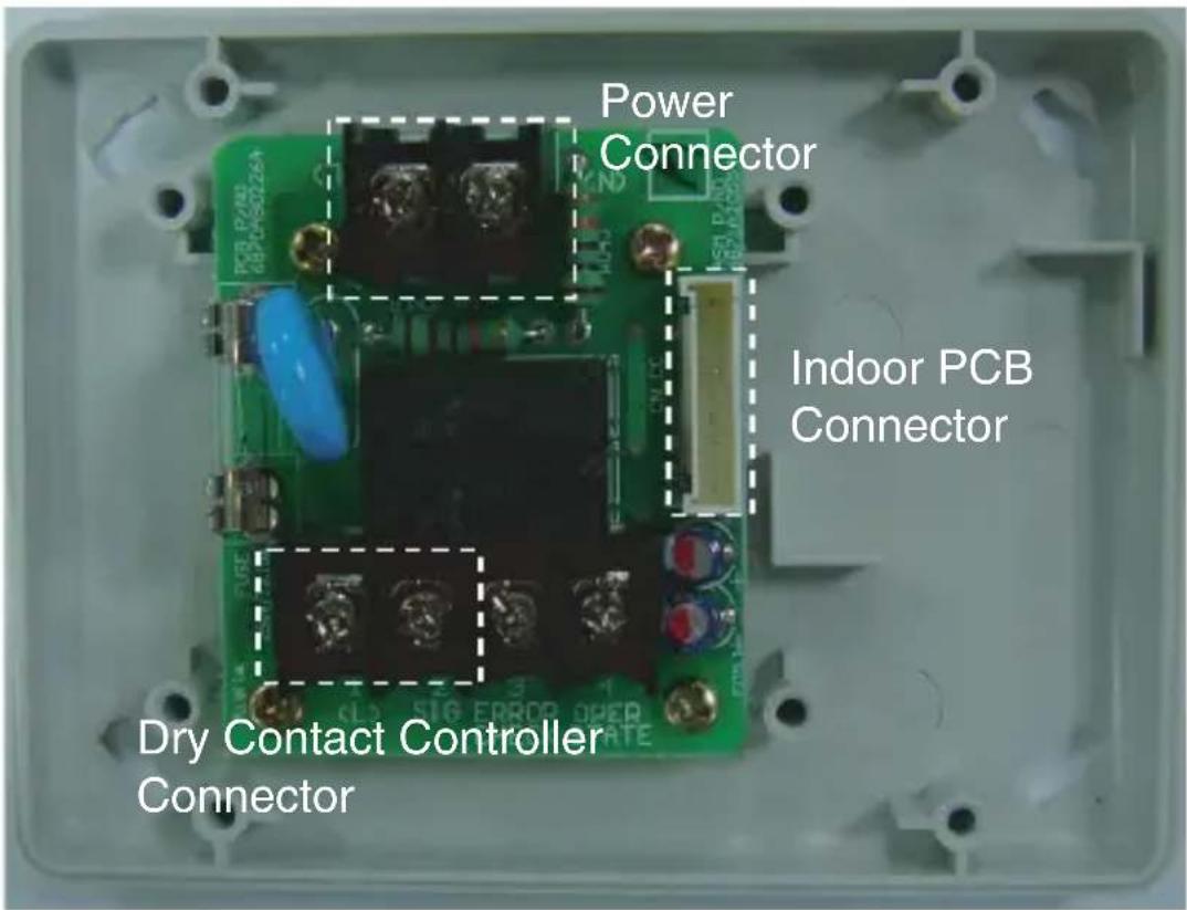
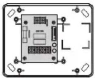
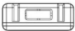
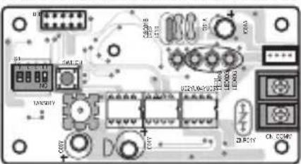
Part Description
PQDSA (Only PCB)
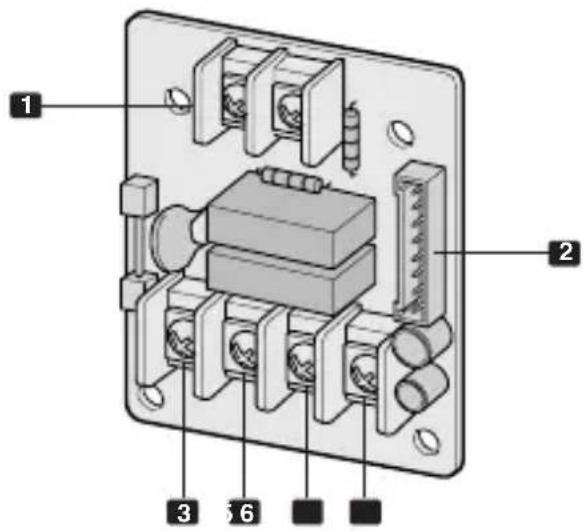
PQDSB (PCB + Case)
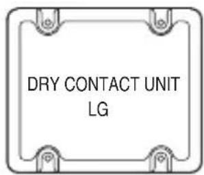
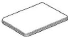
[Top case]
natural_image
Empty rounded rectangle with four corner markers (no text or symbols)[Bottom case]
natural_image
Diagram of a device with labeled ports and connectors, enclosed in a rounded rectangular frame (no text or symbols)[PCB]
[Side]
[Side]
[Side]
1 CN-POWER : AC 220V Connector
2 CN-CC : Indoor PCB Connector
3 CN_DRY (L) : DRY CONTROLLER Connector
4 CN_DRY (SIG) : DRY CONTROLLER Connector
5 CN_DRY (ERROR CHECK): ERROR Check Display Connector
6 CN_DRY( OPER STATE): Operation Display Connector
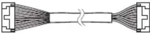
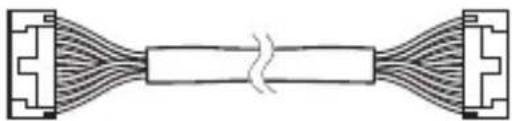
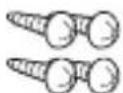
Accessory
Cable 1EA
(for Central controller)
natural_image
Pure diagram of a symmetrical mechanical or electrical component with no text, numbers, or symbols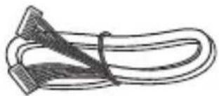
natural_image
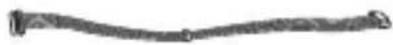
Illustration of a coiled cable with two connectors (no text or symbols)Cable 1EA
(for connecting with indoor unit)
natural_image
Pure electrical circuit lines without any symbols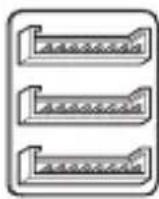
Connecting PCB
(6871A30056A)
*for Central Controller
Dry contact
(For installation, 4EA)

Dry contact - 4EA
(For assembly the case)
User/Installation Manual
\*Note
• These cable using for connection between Dry contact and Indoor unit.
- So before using these things Please check the connector type first and use cables on proper indoor unit.
Installation Guide
Step 1
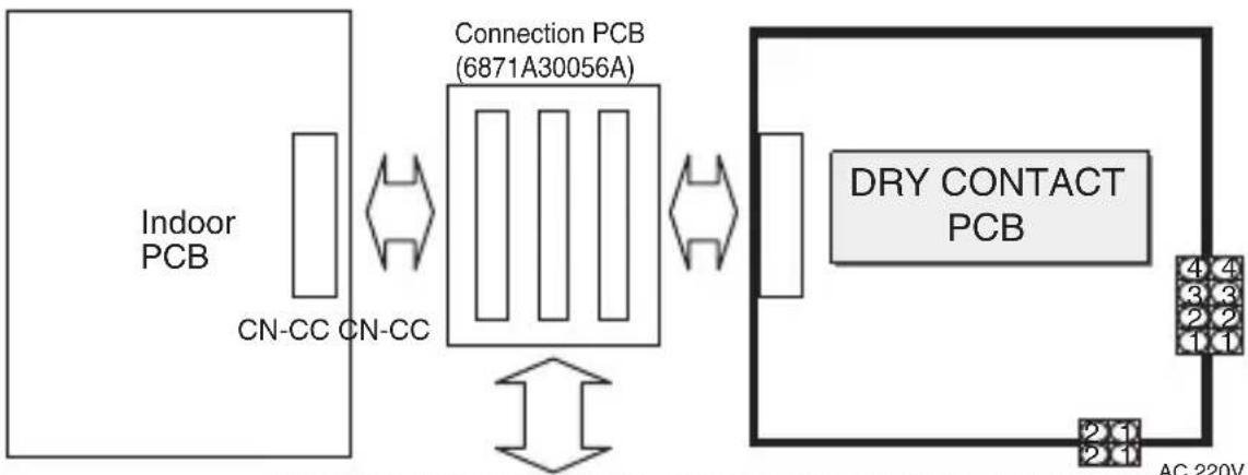
Connect CN-CC with Indoor PCB by the cable(provided)
- Connection of Dry contact only
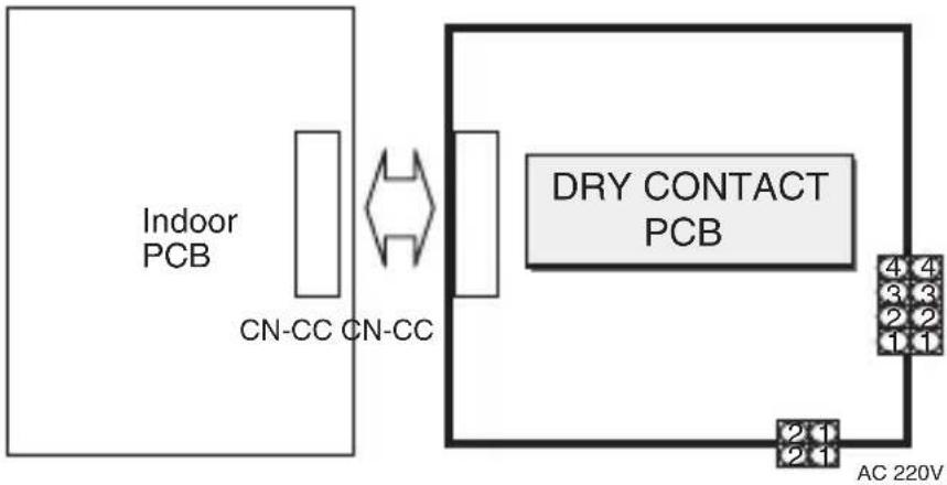
- Connection of Dry contact & LG Central Controller in case of single constant models.
flowchart
graph LR
    A["Indoor PCB"] --> B["CN-CC CN-CC"]
    B <--> C["Connection PCB (6871A30056A)"]
    C <--> D["DRY CONTACT PCB"]
    D --> E["AC 220V"]
    C <--> F["AC 220V"]
    style A fill:#f9f,stroke:#333
    style B fill:#ccf,stroke:#333
    style C fill:#cfc,stroke:#333
    style D fill:#fcc,stroke:#333
    style E fill:#cff,stroke:#333
natural_image
Close-up of an electronic circuit board with various components and connectors (no readable text or symbols)PI485 PCB : Special purchase for Central Control
(Ex : PHNFP14A0 or PSNFP14A0...)
* Single Only
- When you install single product this PCB have to add.
Step 2
Connect CN_DRY with Control Unit. (Fix SUB PCB into the proper location.)
- To apply power source through PCB
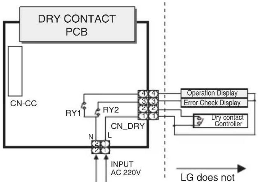
flowchart
graph TD
    A["DRY CONTACT PCB"] --> B["CN-CC"]
    B --> C["RY1"]
    C --> D["RY2"]
    D --> E["CN_DRY"]
    E --> F["N"]
    F --> G["2 1"]
    G --> H["INPUT AC 220V"]
    H --> I["4 4"]
    I --> J["Operation Display"]
    I --> K["Error Check Display"]
    I --> L["Dry contact Controller"]
    L --> M["LG does not"]
    style A fill:#f9f,stroke:#333
    style B fill:#ccf,stroke:#333
    style C fill:#cfc,stroke:#333
    style D fill:#fcc,stroke:#333
    style E fill:#cff,stroke:#333
    style F fill:#ffc,stroke:#333
    style G fill:#cfc,stroke:#333
    style H fill:#fcc,stroke:#333
    style I fill:#cfc,stroke:#333
    style J fill:#fcc,stroke:#333
    style K fill:#cfc,stroke:#333
    style L fill:#fcc,stroke:#333
    style M fill:#cfc,stroke:#333
- To apply power source directly to external source
LG does not supply this section
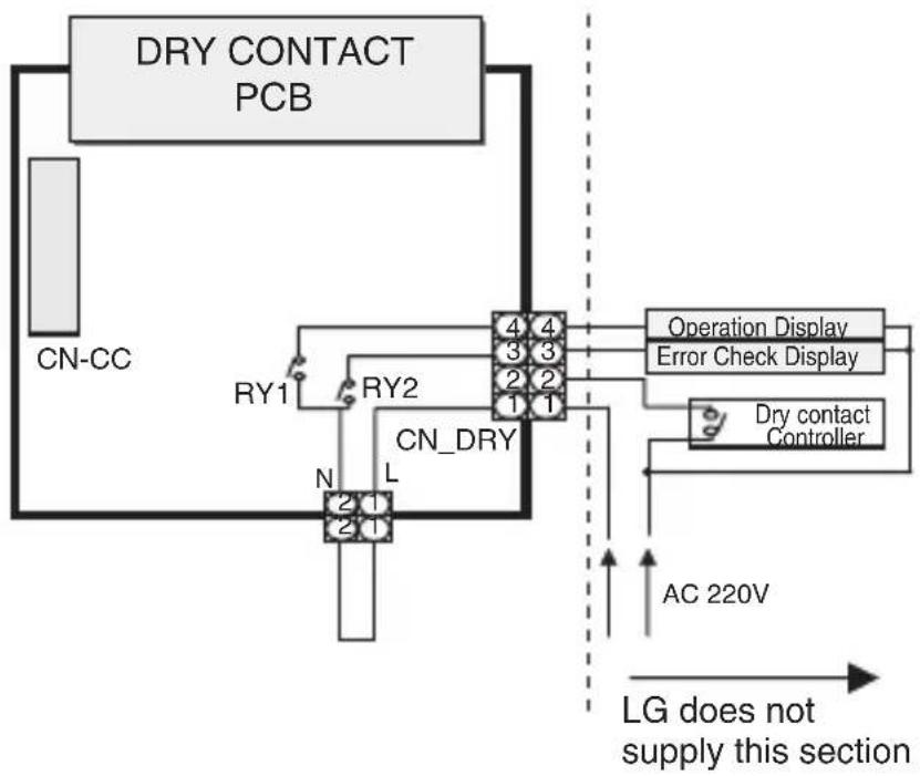
flowchart
graph TD
    A["DRY CONTACT PCB"] --> B["CN-CC"]
    B --> C["RY1"]
    C --> D["RY2"]
    D --> E["CN_DRY"]
    E --> F["N"]
    F --> G["L"]
    G --> H["Operation Display"]
    G --> I["Error Check Display"]
    G --> J["Dry contact Controller"]
    J --> K["AC 220V"]
    K --> L["LG does not supply this section"]
    style A fill:#f9f,stroke:#333
    style L fill:#ccf,stroke:#333
Administrator Guide
\* Function
It gives selection whether to turn ON the unit directly or not from the external source. The selection can be made by pressing CANCEL button of the wireless remote controller 3 times within 3 minutes of resetting the unit with facing it towards the unit. (This function availability depends on indoor unit model)
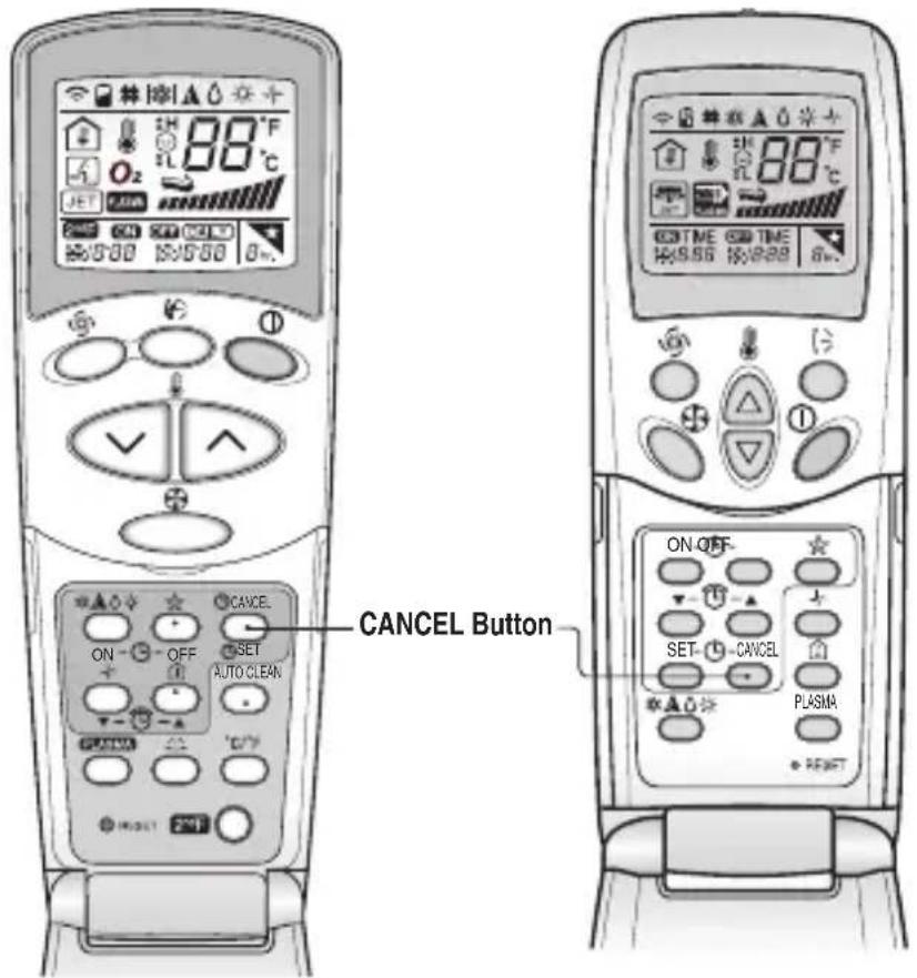
- To turn ON the unit directly from the external source
- Not to turn ON the unit directly from the external source. Only to activate the system.

If the power gives out, the Air conditioner may be run to before state after power returns because Air conditioner's function of interruption of electric power compensation.