
A-114 - Synthesizer Doepfer - Free user manual and instructions
Find the device manual for free A-114 Doepfer in PDF.


| Product Type | Eurorack Synthesizer Module |
| Model | A-114 |
| Brand | Doepfer |
| Function | Dual Ring Modulator |
| Width | 8 HP (40.3 mm) |
| Depth | 40 mm (approx.) |
| Weight | 80 g (approx.) |
| Power Supply | +12V: 20 mA, -12V: 20 mA |
| Power Connector | 16-pin ribbon cable (Doepfer standard) |
| Audio Inputs | 2 x 3.5 mm mono jacks (modulator 1 & 2) |
| Carrier Inputs | 2 x 3.5 mm mono jacks (carrier 1 & 2) |
| Audio Outputs | 2 x 3.5 mm mono jacks (output 1 & 2) |
| Front Panel Material | Aluminum, 2 mm thickness |
| Circuit Board | FR4, double-sided, plated through holes |
| Operating Temperature | 10°C to 40°C |
| Humidity | 0% to 85% (non-condensing) |
| Maintenance | Clean with soft dry cloth; avoid liquids |
| Safety | Disconnect power before installing or removing modules |
| Spare Parts | Not available; contact Doepfer for repairs |
| Warranty | 2 years from date of purchase |
Frequently Asked Questions - A-114 Doepfer
User questions about A-114 Doepfer
0 question about this device. Answer the ones you know or ask your own.
Ask a new question about this device
Download the instructions for your Synthesizer in PDF format for free! Find your manual A-114 - Doepfer and take your electronic device back in hand. On this page are published all the documents necessary for the use of your device. A-114 by Doepfer.
USER MANUAL A-114 Doepfer
1. Introduction
Module A-114 (Dual Ring Modulator) contains two separate ring modulators.
A ring modulator outputs the product (Multiplication X • Y) of the signals at inputs X and Y. It's similar to a VCA, but whereas a VCA only responds to positive voltages at the inputs (2-quadrant multiplication), the ring modulator responds to both positive and negative voltages (4-quadrant multiplication).
The ring modulator thus provides a refinement of amplitude modulation (AM). Ordinary amplitude modulation will output the original carrier frequency f_c as well as the two side bands ( f_c - f_M, f_c + f_M ) for each of the spectral components of the carrier and modulation signals - but ring modulation cancels out the carrier frequencies, and just lets the side-bands pass to the output (see Fig. 1).
A ring modulator is used for the production of bell-like sounds, alien voices, or just to produce new timbres.
2. Dual Ring Modulator - Overview
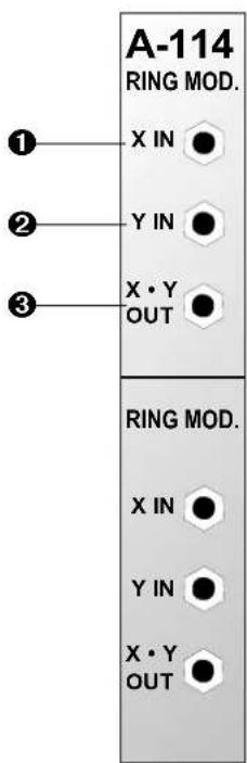
In / Outputs:
① X In : Signal input
② Y In : Signal input
③ X*Y Out : Output
3. In / Outputs
① X In • ② Y In
Sockets ① and ② are the signal inputs for the A-114. Patch the signals you would like to ring modulate into these sockets.
The inputs need to have AC signals - so you should use audio signals, not control voltages. For control voltages, use a VCA.
③ X\*Y Out
Socket ③ is the ring modulator Output.
4. User examples
Basic ring modulation
Fig. 1 shows a basic form of ring modulation using two sine waves. This patch can provide bell- and vibes - like sounds.
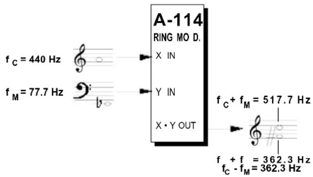
Fig. 1: Ring modulation with two sine waves
Ring modulation of audio signals
A ring modulator is very good at doing weird things to audio signals (for instance, voices, strings, sax).
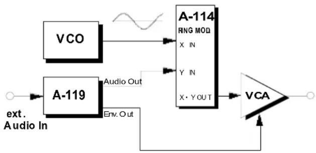
The example at Fig. 2 shows an audio signal (input via module A-119 "Ext. In") ring modulated with a sine wave. The spectrum at the output contains the sum and difference of the frequency of the sine wave with every single one of the components of the audio signal's sound spectrum.
flowchart
graph LR
    A["VCO"] --> B["A-114"]
    C["A-119"] --> D["Audio Out"]
    C --> E["Env. Out"]
    B --> F["RNG MOD"]
    B --> G["X IN"]
    B --> H["Y IN"]
    B --> I["X·Y OUT"]
    D --> J["VCA"]
    E --> J
    F --> J
    G --> J
    H --> J
    I --> J
    J --> K["Output"]
Fig. 2: Ring modulation of an external audio signal.
In this patch, the A-119 performs two functions.
On the one hand, it's bringing the level of the external signal up to the A-100's operating level (round about 5 V_ss ).
On the other hand, it's also sending the envelope follower output (the envelope generated by the external audio signal) to a VCA. This is necessary because the ring modulator doesn't completely shut off when there's 0V input. The VCO is still just audible, at approximately -50 to -60dB, even when there's no external audio signal. The VCA gates it completely.

Experiment with this set-up, for instance by replacing the sine wave with other waveforms (eg. sawtooth, square wave, etc.)
The waveform you use can itself also be modulated (for instance by PWM, AM, FM, or audio signal).
"Glissando ring modulation"
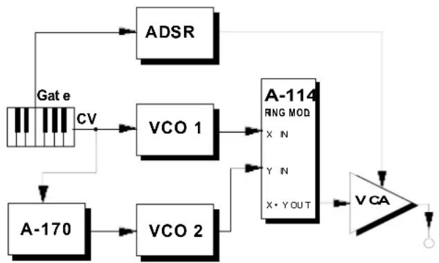
The patch in Fig. 3. produces some interesting sounds. Input two VCOs set to an exact harmonic interval (eg. a fifth or octave) into the ring modulator. Send the pitch CV direct to the first VCO, but run the second oscillator's CV through the upper section of the slew limiter (A-170) first.
Whenever the pitch CV changes, the ring modulation causes gradual changes in the sound spectrum.
flowchart
graph TD
    A["Gate"] -->|CV| B["VCO 1"]
    A --> C["A-170"]
    B --> D["A-114 RNG MOD\nX N\nY N\nX·Y OUT"]
    C --> E["VCA"]
    D --> F["VCA"]
    E --> F
    F --> G["Output"]
Fig. 3: "Glissando ring modulation"

Use the upper part of the A-170 for this, because the diode offset in the lower part will put the VCO out of tune.
A-114 Dual Ring Modulator
System A - 100
DOEPFER
5. Patch-Sheet
The following diagrams of the module can help you recall your own Patches. They're designed so that a complete 19" rack of modules will fit onto an A4 sheet of paper.
Photocopy this page, and cut out the pictures of this and your other modules. You can then stick them onto another piece of paper, and create a diagram of your own system.
Make multiple copies of your composite diagram, and use them for remembering good patches and set-ups.

- Draw in patchleads with colored pens.



Brand : Doepfer
Model : A-114
Category : Synthesizer