
Apollo AP-DA214 - Receiver Fusion - Free user manual and instructions
Find the device manual for free Apollo AP-DA214 Fusion in PDF.


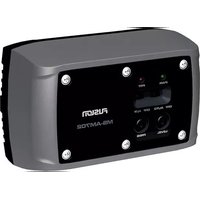
| Type | Marine amplifier (receiver) |
| Brand | Fusion |
| Model | Apollo AP-DA214 |
| Amplifier Class | Class D |
| Number of Channels | 2 |
| Rated Power Output (4 Ohm) | 20 W RMS x 2 |
| Rated Power Output (2 Ohm) | 30 W RMS x 2 |
| Peak Power Output | 140 W |
| Frequency Response | 20 Hz – 20 kHz |
| Signal-to-Noise Ratio (rated power, 4 Ohm) | 99 dB |
| Signal-to-Noise Ratio (1 W, 4 Ohm) | 86 dB |
| Input Sensitivity | 450 mV |
| Input Impedance | 9 kOhm |
| Operating Voltage | 10.8 – 32 Vdc |
| Current Draw (standby/off) | 1 mA |
| Current Draw (idle) | 0.04 A |
| Current Draw (max) | 10 A |
| Remote Turn-On Voltage | Greater than 4 Vdc |
| Protection Circuits | Reverse voltage, input under/over voltage, over temperature, output short circuit |
| Water Rating | IEC 60529 IPX7 |
| Operating Temperature Range | 0 to 50°C (32 to 122°F) |
| Storage Temperature Range | -20 to 70°C (-4 to 158°F) |
| Compass-Safe Distance | 20 cm (7.9 in.) |
| Dimensions (W x H x D) | 115 x 48 x 100 mm (4.5 x 1.9 x 3.9 in.) |
| Weight | 460 g (1 lb) |
| Compatibility | Fusion DSP-enabled marine audio systems only |
| Configuration | Via Fusion-Link app |
| Mounting | Bracket with release tab |
| Included Accessories | Wiring harness, mounting bracket, pan-head screws |
Frequently Asked Questions - Apollo AP-DA214 Fusion
User questions about Apollo AP-DA214 Fusion
0 question about this device. Answer the ones you know or ask your own.
Ask a new question about this device
Download the instructions for your Receiver in PDF format for free! Find your manual Apollo AP-DA214 - Fusion and take your electronic device back in hand. On this page are published all the documents necessary for the use of your device. Apollo AP-DA214 by Fusion.
USER MANUAL Apollo AP-DA214 Fusion

AVIS
AVVISO
HINWEIS
AVSO
AVISO
LETOP
BEMAERK
JOMAUTUS
ES DETTE
OBS!
注意
訊系統的放大器。此放大器僅與具備
且因放大器功率輸出,可能會造成第三方喇
[Non-Text]
NOTICE YOU MUST NOT USE THIS AMPLIFIER WITH ANY THIRD-PARTY MARINE AUDIO SYSTEMS. This amplifier is compatible only with Fusion® DSP-enabled marine audio equipment and may cause damage to third-party speakers due to the amplifier power output.
See the Important Safety and Product Information guide in the product box for product warnings and other important information.
This device must be installed according to these instructions.
Disconnect the vessel's power supply before beginning to install this device.
CAUTION
Continuous exposure to sound pressure levels over 100 dBA may cause permanent hearing loss. The volume is typically too loud if you cannot hear people speaking around you. Limit the amount of time you listen at high volume. If you experience ringing in your ears or muffled speech, stop listening and have your hearing checked.
To avoid possible personal injury, always wear safety goggles, ear protection, and a dust mask when drilling, cutting, or sanding.
NOTICE
YOU MUST NOT USE THIS AMPLIFIER WITH ANY THIRD-PARTY MARINE AUDIO SYSTEMS. This amplifier is compatible only with Fusion DSP-enabled marine audio equipment and may cause damage to third-party speakers due to the amplifier power output.
When drilling or cutting, always check what is on the opposite side of the surface to avoid damaging the vessel.
It is strongly recommended that you have your audio system installed by a professional installer to ensure optimum performance.
You must read all installation instructions before beginning the installation. If you experience difficulty during the installation, go to support.garmin.com for product support.
After installing an audio system, you should run the connected speakers and subwoofers at low to medium volumes for the first few hours of use. This helps to improve the overall sound by gradually loosening up the moving components of new speakers and subwoofers, such as the cone, spider, and surround. See the installation instructions provided with your speakers, because there may be more details about the recommended time for each model.
Tools Needed
- Drill
- 2.7 mm ( 7/64 in.) drill bit (or a drill bit appropriate for your provided mounting hardware and mounting-surface material)
• #2 Phillips Screwdriver - Wire cutter
- Wire stripper
• Solder and heat-shrink tubing - Wires and cables:
-16 AWG (1.31 mm 2 ) copper-coated aluminum power wire
-18 AWG (0.82 mm 2 ) tinned copper speaker wire
NOTE: You may need thicker wire for longer runs.
-20 AWG (0.52 mm 2 ) wire for the REMOTE ON signal
°2-way RCA cable
- Cable ties (optional)
Mounting Considerations
CAUTION
In high ambient temperatures and after extended use, the device enclosure may reach temperatures deemed dangerous to touch. To avoid possible personal injury, the device must be installed in a location where it will not be touched during operation.
NOTICE
This device should be mounted in a well-ventilated location that is not exposed to extreme temperatures or conditions. The temperature range for this device is listed in the product specifications. Extended exposure to temperatures exceeding the specified temperature range, in storage or operating conditions, may cause device failure. Extreme-temperature-induced damage and related consequences are not covered by the warranty.
If you are mounting the device on fiberglass, when drilling the pilot holes, use a countersink bit to drill a clearance counterbore through only the top gel-coat layer. This will help to avoid cracking in the gel-coat layer when the screws are tightened.
When selecting a mounting location, observe these considerations:
- You must mount the device in a location that provides at least 25 mm (1 in.) of clearance on all sides to help with proper ventilation.
- You must mount the device in a location that does not interfere with the fuel tank or electrical wiring.
- You must mount the device in a location where it is not exposed to fuel or fuel vapor.
- You must mount the device in a location with adequate ventilation where it is not exposed to extreme temperatures.
- If you mount device in an enclosed space, you should install a cooling fan with appropriate ducts to aid in airflow.
- You should mount the device so that the cables can be connected easily.
- To avoid interference with a magnetic compass, you should mount the device the specified distance away from a compass. This distance is listed in the specifications section.
- You must not mount the device in close proximity to other navigation-critical equipment, antennas, or radio-communication equipment on the vessel.
Installing the Mounting Bracket
NOTICE
Pan-head screws are included, but they may not be suitable for the mounting surface. If you provide different mounting hardware, you must not use fasteners with a countersunk head. Hardware with a countersunk head will damage the mounting bracket.
Before you install the mounting bracket, you must select a mounting location and determine what screws and other mounting hardware are needed for the surface.
1 Use mounting bracket as a template, verify that the mounting location has sufficient clearance to install the device and mark the mounting holes.
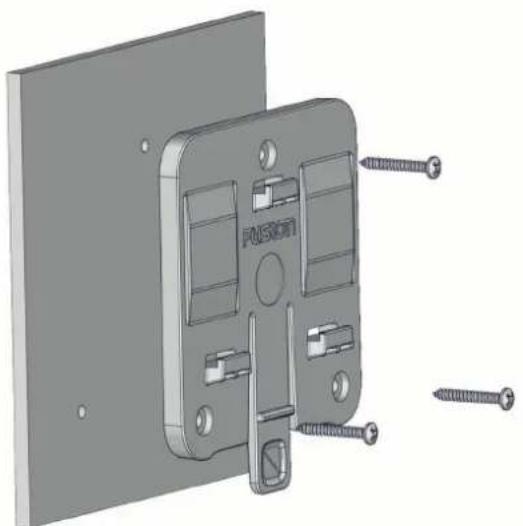
NOTE: You must install the bracket with the release tab pointing down to properly secure the amplifier in the bracket.
2 Using a 2.7 mm ( 7/64 in.) bit or a bit appropriate for your provided hardware and mounting-surface material, drill the pilot holes you marked in the previous step.
NOTICE
If you are mounting the device on fiberglass, when drilling the pilot holes, use a countersink bit to drill a clearance counterbore through only the top gel-coat layer. This will help to avoid cracking in the gel-coat layer when the screws are tightened.
3 Using the included pan-head screws or other pan-head mounting hardware, secure the bracket to the mounting surface.
NOTICE
You must use pan-head screws, because countersunk screws will damage the bracket.
Attaching the Device to the Mounting Bracket
You must secure the mounting bracket to the surface before you can attach the device.
1 Hold the device over and slightly above the mounting bracket. ①
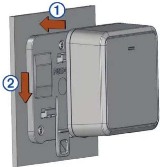
2 Place the device onto the bracket and pull down until the tab audibly clicks.
Removing the Device from the Mounting Bracket
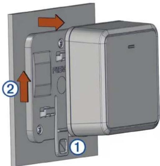
Press the tab ① on the mounting bracket, and lift up ② on the amplifier to disconnect it from the mount.
Connection Considerations
NOTICE
You should turn off the audio system before making any connections to the amplifier. Failure to turn off the audio system may result in damage to the audio system.
All terminals and connections must be protected from contact with the vessel chassis and with each other. Improper terminal or wire contact may result in damage to the audio system.
NOTE: You must connect the amplifier to the AMPLIFIER ON wire from the stereo for the amplifier to turn on and off with the stereo.
Wiring Harness Information
NOTICE
You should make all bare wire connections using solder and heat shrink tubing or another type of secure waterproof connector.
![graph LR A["Central Connector"] --> B["1"] A --> C["2"] A --> D["3"] A --> E["4"] A --> F["5"]](/content/2026/05/821093/images/708ae34a174b06f6cba7ea1400adba76b2b3a5f0ba95a7c4f16f7a66cf4f763a.jpg)

Power wires:
- Red: positive (+)
- Black: ground (-)

RCA input connectors:
- Red: right
- White: left
This must connect to the zone output from your stereo using a 2-way RCA cable (not included)

REMOTE ON signal wire (blue)

Right speaker wires:
- Gray: positive (+)
- Gray/black: negative (-)

Left speaker wires:
- White: positive (+)
- White/black: negative (-)
Connecting to Power
CAUTION
The wiring from the power source to the amplifier must run through an inline fuse or circuit breaker (not included) as close to the power source as possible. You must connect the positive wire to the fuse or circuit breaker. Connecting the amplifier to power without an inline fuse or circuit breaker may result in a fire if there is a short in the cable.
If the amplifier is powered by a battery, you should connect it through a fuse or circuit breaker rated for 15 A. If the amplifier is powered by a source other than a battery, use a breaker or fuse rated no higher than the max current of the power source.
NOTICE
You should make all wiring connections using solder and heat shrink tubing or another type of secure waterproof connector.
You should use 16 AWG (1.31 mm 2 ) copper-coated aluminum wire (not included) to extend the power and ground wires for most installations. For long power-cable runs, you should consider using larger-diameter (smaller gauge number) wire to minimize power loss. If you are using pure copper wire instead of copper-coated aluminum, you can use a smaller-diameter (larger gauge number) wire because of the increased material conductivity.
You must connect the REMOTE ON wire from the amplifier wiring harness to either the AMPLIFIER ON wire from the connected stereo or to a constant 12 or 24 Vdc power source using a switch. Connecting to the AMPLIFIER ON wire is recommended to avoid a popping sound when the stereo turns on or off.
NOTE: The stereo and the amplifier must both connect to a common ground or the REMOTE ON signal will not turn on the amplifier with the stereo. If the amplifier is connected to a 24 Vdc source and the stereo is connected to a 12 Vdc source, make sure that they connect to a common ground for proper operation.
1 Route the red POWER wire ① to a circuit breaker or fuse rated for 15 A ②, and route the black GROUND wire ③ to the battery.
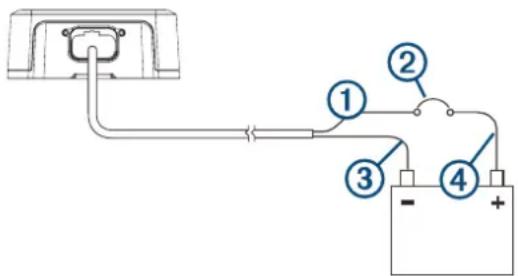
2 If necessary, route a wire between the circuit breaker and the battery.
3 If necessary, route the wiring-harness plug to the amplifier.
Do not connect the wiring harness to the amplifier until after all of the bare wire connections have been made.
4 Connect the black wire to the negative (-) battery terminal.
5 Connect the red power wire to the fuse or circuit breaker, and connect the fuse or circuit breaker to the positive (+) battery terminal if necessary.
6 Connect the wiring harness plug to the amplifier.
Configuring the Amplifier
To configure the amplifier for use with your stereo and speakers, you must use the Fusion-Link™ app to set up the DSP profile after you have completed the connections.
1 Follow the instructions in your stereo owner's manual to download the Fusion-Link app and connect it to the stereo.
2 Select the appropriate amplifier, speakers, and/or subwoofer(s) for each zone in the Fusion-Link app.
3 Follow the instructions in the Fusion-Link app to select a configured profile for the connected amplifier, speakers, and/or subwoofer(s).
4 Send the DSP profile to the connected stereo and test the sound.
5 Repeat steps 3 and 4 until the audio system sounds satisfactory.
Specifications
| Compass-safe distance 20 cm (7.9 in.) | |
| Operating temperature range From 0 to 50°C (from 32 to 122°F) | |
| Storage temperature range From -20 to 70°C (from -4 to 158°F) | |
| Water rating IEC 60529 IPX7 | 1 |
| Weight 460 g (1 lb) | |
| Amplifier class Class D | |
| Frequency response 20 Hz to 20 kHz | |
| Rated power output (@ 14.4 Vdc input < 1% THD+N (EIA/CEA-490A)) | 4 Ohm: 20 W RMS (×2)2 Ohm: 30 W RMS (×2) |
| Peak power output 140 w | |
| Input impedance 9 kOhm | |
| Input sensitivity 450 mV | |
| Signal to noise ratio @ rated power output, 4 Ohm 99 dB | |
| Signal to noise ratio @ 1 W, 4 Ohm 86 dB | |
| Separation/crosstalk 72 dB | |
| Operating voltage 10.8 to 32 Vdc | |
| Current draw, in standby/off using REMOTE ON wire (@14.4 Vdc input) | 1 mA |
| Current draw, idle (@14.4 Vdc input) 0.04 A | |
| Current draw, max (@14.4 Vdc input, 2 Ohm) 10 A | |
| Breaker or cable-fuse rating | If the amplifier is powered by a battery, use a breaker or fuse rated for 15 A.If the amplifier is powered by a source other than a battery, use a breaker or fuse rated no higher than the max current of the power source. |
| Remote turn-on | Greater than 4 Vdc |
| Protection circuits | Reverse voltageInput under/over voltageOver temperatureOutput short circuit |
Dimensions
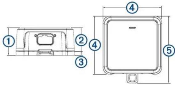
① 48 mm ( 17/8 in.)
② 40 mm ( 19/16 in.)
③ 8 mm ( 5/16 in.)
④ 100 mm ( 39/16 in.)
⑤ 115 mm ( 41/2 in.)
More Information
Troubleshooting
Before you contact your Fusion dealer or service center, you should perform a few simple troubleshooting steps to help diagnose the problem.
If the Fusion amplifier has been installed by a professional installation company, you should contact the company so a technician can assess the problem and advise you about possible solutions.
LED Power Indicator Bar Colors
The single LED power indicator bar on the front of the amplifier changes colors to indicate status and potential faults. You can use these tables to reference the LED colors when troubleshooting the amplifier.
| LED Color Status | |
| Off Power off | |
| Green Operational | |
| Orange Recoverable fault | |
| Red Critical fault | |
LED is Off
| Potential Cause | Potential Resolution |
| Power connection issue | Check the power wiring connections on the wiring harness and power-wire extensions, and make sure there is a secure, waterproof connection on all wires.Check the connection between the wiring harness and the amplifier, and make sure it is seated securely in the port.Check the power-wiring connections to the fuse or circuit breaker and to the battery and repair or tighten any disconnected or loose wires.Check the circuit breaker and reset it if necessary.Make sure the supply voltage is within the specified operational range for the amplifier.Make sure you are using the appropriate gauge for the length of the power cable run, and replace the cable with a thicker gauge, if needed. |
| Remote turn-on wire connection issue | Check the remote turn-on wire connection to the wiring harnesses on the amplifier and the stereo, as well as any wire extensions, and make sure there is a secure, waterproof connection on all wires.Make sure that the stereo and the amplifier are connected to a common power ground.If you connected the remote turn-on wire to a switch instead of the stereo, make sure the switch is installed correctly. |
LED is Green and There is No Sound
| Potential Cause | Potential Resolution |
| Power or volume issue | Make sure the stereo is powered on.Make sure the volume is not set too low or muted. |
| DSP settings issue | Check the DSP settings in the Fusion-Link app and make sure the correct speakers, stereo, and amplifier are selected.NOTE: You must select the option in the app to send the DSP settings to the devices after you configure the settings. |
| Signal or speaker connection issue | Check the RCA cable connections to the stereo and the amplifier, and re-connect all disconnected cables, if needed.Check the speaker wiring connections to the wiring harness on the amplifier and to the speakers, as well as any wire extensions, and make sure there is a secure, waterproof connection on all wiresCheck the wire gauge used to connect the speakers to the amplifier, and make sure it is appropriate for the length of the wire run. |
Potential Cause Potential Resolution
| Power issue | Check the power cables to make sure they are the appropriate gauge, are fused, and are connected properly. |
LED is Green the Sound is not Optimal
| Issue Potential Resolution | |
| There is a hum or other unexpected noise from a speaker | Install ground-loop isolators inline with the RCA cables from the stereo. NOTE: You should install ground-loop isolators on the RCA cables where they connect to the stereo, not where they connect to the amplifier. |
| The sound is distorted or clipping | Check the DSP settings in the Fusion-Link app and make sure the correct speakers, stereo, and amplifier are selected. NOTE: You must select the option in the app to send the DSP settings to the devices after you configure the settings. |
LED is Orange
| Potential Cause Potential | Resolution |
| Power supply under- or over-voltage issue | Check the input power to make sure it is within the 10.8 to 32 Vdc operational range for the amplifier. |
| Power wire gauge issue | Check the wire gauge used to connect the amplifier to power, and make sure it is appropriate for the length of the wire run. |
| Over-temperature issue | Check the temperature of the amplifier and make sure it is under 50°C (122°F). If the amplifier is hotter than the operational temperature rating, add ventilation to the installation location or mount the amplifier in a different location. |
NOTE: The amplifier will automatically attempt to recover from a recoverable fault (orange LED). If multiple attempts of recovery are not successful, then the amplifier will transition to a critical fault status (red LED). You can power cycle the amplifier or toggle the REMOTE ON signal to reset the critical fault.
LED is Red
| Potential Cause Potential Resolution | |
| Power supply under- or over-voltage issue | Check the input power to make sure it is within the specified voltage operating range for the amplifier.If the amplifier experiences a number of under-voltage faults (orange LED) in a short period of time, it will consider the issue a critical fault and change the LED color to red. Therefore, a series of orange indicators followed by a red indicator may be due to an under-voltage issue. |
| Prolonged over-temperature issue | Check the temperature of the amplifier and make sure it is under 50°C (122°F). If the amplifier is hotter than the operational temperature rating, add ventilation to the installation location or mount the amplifier in a different location. |
| DSP setting or volume issue | Check the DSP settings in the Fusion-Link app and make sure the correct amplifier, speakers, and/or subwoofer(s) are selected.NOTE: You must select the option in the app to send the DSP settings to the stereo after you configure the settings. |
| High-volume issue | Reduce the volume. |
| Speaker fault Check all connected speaker wires. | |
Potential Cause Potential Resolution
- Check the speaker wiring connections to the wiring harness on the amplifier and to the speakers, as well as any wire extensions, and make sure there is a secure, waterproof connection on all wires
- Make sure there are no shorts in the speaker wires, and that there are no cuts in the speaker-wire jackets that may result in a short.
| Internal amplifier or power supply fault | Disconnect the amplifier from the power source for one minute, then reconnect it and test for proper operation. If the LED continues to show a red fault, contact support. |
物質宣言

- AVIS
- AVVISO
- HINWEIS
- AVSO
- AVISO
- LETOP
- BEMAERK
- JOMAUTUS
- ES DETTE
- OBS
- 注意
- CAUTION
- NOTICE
- TOOLS NEEDED
- MOUNTING CONSIDERATIONS
- INSTALLING THE MOUNTING BRACKET
- ATTACHING THE DEVICE TO THE MOUNTING BRACKET
- REMOVING THE DEVICE FROM THE MOUNTING BRACKET
- CONNECTION CONSIDERATIONS
- WIRING HARNESS INFORMATION
- CONNECTING TO POWER
- CONFIGURING THE AMPLIFIER
- DIMENSIONS
- MORE INFORMATION
- TROUBLESHOOTING
- LED POWER INDICATOR BAR COLORS
- POTENTIAL CAUSE POTENTIAL RESOLUTION
Brand : Fusion
Model : Apollo AP-DA214
Category : Receiver