
NVS-34 - Media player DataVideo - Free user manual and instructions
Find the device manual for free NVS-34 DataVideo in PDF.


| Product Type | Video Streaming Server / Media Player |
| Brand | DataVideo |
| Model | NVS-34 |
| Dimensions (L x W x H) | 220 mm x 95 mm x 47 mm |
| Weight | 0.7 kg |
| Power Supply | DC 12V, 11W |
| Video Inputs | HDMI x1, SDI x1 |
| Audio Inputs | SDI/HDMI embedded audio, RCA unbalanced audio pair |
| Video Encoding | H.264/AVC, Main/High Profile Level 4.1 |
| Video Bitrate (Record+Stream) | Up to 36 Mbps |
| Video Bitrate (Stream Only) | Up to 10 Mbps |
| Video Bitrate (Record Only) | Up to 16 Mbps |
| Audio Bitrate | Stereo: 64–384 Kbps, Mono: 32–192 Kbps |
| Streaming Protocols | TS (UDP/TCP), RTSP (HTTP/TCP/UDP), RTMP/RTMPS (Publish), HLS |
| Recording File Format | MP4 |
| Storage Media | SD Card (Class 10 or above, FAT32/NTFS/exFAT) |
| Network Interface | RJ-45 Ethernet 10/100 Mbps |
| Special Features | Simultaneous stream & record, CG text overlay, vertical video (rotate/crop), web UI control, bicolor LEDs |
| Operating Temperature | 0°C to 40°C |
| Safety Precautions | Do not expose to water, clean with damp cloth, ensure ventilation, use only supplied power adapter |
| Maintenance | Wipe exterior with soft dry cloth; do not use liquid cleaners |
| Spare Parts & Repairability | Contact authorized Datavideo service center; no user-serviceable parts inside |
Frequently Asked Questions - NVS-34 DataVideo
User questions about NVS-34 DataVideo
0 question about this device. Answer the ones you know or ask your own.
Ask a new question about this device
Download the instructions for your Media player in PDF format for free! Find your manual NVS-34 - DataVideo and take your electronic device back in hand. On this page are published all the documents necessary for the use of your device. NVS-34 by DataVideo.
USER MANUAL NVS-34 DataVideo
WARNINGS AND PRECAUTIONS 4
WARRANTY 5
STANDARD WARRANTY....5
THREE YEAR WARRANTY....6
DISPOSAL 6
1 INTRODUCTION....7
1.1 FEATURES 7
1.2 SYSTEM DIAGRAM 8
2 CONNECTIONS AND CONTROL 9
2.1 FRONT PANEL....9
2.2 REAR PANEL....11
3 VIDEO STREAMING 13
3.1 STREAMING NETWORK CONNECTION AND DEVICE SEARCH....13
Connecting to a DHCP Network (DHCP Mode) 13
Connecting to a NON-DHCP Network (Static IP) 14
Device Reset 14
Troubleshooting the Network Connection.... 15
3.2 WEB USER INTERFACE....16
Source....16
Operation Mode 19
CG....31
System 33
Status 37
Vertical 38
3.3 OPERATIONS 39
Video Streaming 39
Text Overlay Video 47
3.4 STREAM AND RECORD BUTTONS 49
Input Button 49
Record Button....49
Stream Button 50
Bitrate Button....51
Vertical Button 51
3.5 RESTORING FACTORY DEFAULTS 51
3.6 FIRMWARE UPDATE....52
4 FIRMWARE UPGRADE 53
5 RECOMMENDED SD CARDS 56
6 FREQUENTLY-ASKED QUESTIONS 59
7 DIMENSIONS....60
8 SPECIFICATIONS 61
SERVICE AND SUPPORT 64
Disclaimer of Product & Services
The information offered in this instruction manual is intended as a guide only. At all times, Datavideo Technologies will try to give correct, complete and suitable information. However, Datavideo Technologies cannot exclude that some information in this manual, from time to time, may not be correct or may be incomplete. This manual may contain typing errors, omissions or incorrect information. Datavideo Technologies always recommend that you double check the information in this document for accuracy before making any purchase decision or using the product. Datavideo Technologies is not responsible for any omissions or errors, or for any subsequent loss or damage caused by using the information contained within this manual. Further advice on the content of this manual or on the product can be obtained by contacting your local Datavideo Office or dealer.
FCC Compliance Statement
This device complies with part 15 of the FCC rules. Operation is subject to the following two conditions:
(1) This device may not cause harmful interference, and
(2) This device must accept any interference received, including interference that may cause undesired operation.
Warnings and Precautions
-
Read all of these warnings and save them for later reference.
-
Follow all warnings and instructions marked on this unit.
-
Unplug this unit from the wall outlet before cleaning. Do not use liquid or aerosol cleaners. Use a damp cloth for cleaning.
-
Do not use this unit in or near water.
-
Do not place this unit on an unstable cart, stand, or table. The unit may fall, causing serious damage.
-
Slots and openings on the cabinet top, back, and bottom are provided for ventilation. To ensure safe and reliable operation of this unit, and to protect it from overheating, do not block or cover these openings. Do not place this unit on a bed, sofa, rug, or similar surface, as the ventilation openings on the bottom of the cabinet will be blocked. This unit should never be placed near or over a heat register or radiator. This unit should not be placed in a built-in installation unless proper ventilation is provided.
-
This product should only be operated from the type of power source indicated on the marking label of the AC adapter. If you are not sure of the type of power available, consult your Datavideo dealer or your local power company.
-
Do not allow anything to rest on the power cord. Do not locate this unit where the power cord will be walked on, rolled over, or otherwise stressed.
-
If an extension cord must be used with this unit, make sure that the total of the ampere ratings on the products plugged into the extension cord do not exceed the extension cord rating.
-
Make sure that the total amperes of all the units that are plugged into a single wall outlet do not exceed 15 amperes.
-
Never push objects of any kind into this unit through the cabinet ventilation slots, as they may touch dangerous voltage points or short out parts that could

result in risk of fire or electric shock. Never spill liquid of any kind onto or into this unit.
-
Except as specifically explained elsewhere in this manual, do not attempt to service this product yourself. Opening or removing covers that are marked “Do Not Remove” may expose you to dangerous voltage points or other risks, and will void your warranty. Refer all service issues to qualified service personnel.
-
Unplug this product from the wall outlet and refer to qualified service personnel under the following conditions:
a. When the power cord is damaged or frayed;
b. When liquid has spilled into the unit;
c. When the product has been exposed to rain or water;
d. When the product does not operate normally under normal operating conditions. Adjust only those controls that are covered by the operating instructions in this manual; improper adjustment of other controls may result in damage to the unit and may often require extensive work by a qualified technician to restore the unit to normal operation;
e. When the product has been dropped or the cabinet has been damaged;
f. When the product exhibits a distinct change in performance, indicating a need for service.
Warranty
Standard Warranty
- Datavideo equipment are guaranteed against any manufacturing defects for one year from the date of purchase.
- The original purchase invoice or other documentary evidence should be supplied at the time of any request for repair under warranty.
- The product warranty period beings on the purchase date. If the purchase date is unknown, the product warranty period begins on the thirtieth day after shipment from a Datavideo office.
- All non-Datavideo manufactured products (product without Datavideo logo) have only one year warranty from the date of purchase.
- Damage caused by accident, misuse, unauthorized repairs, sand, grit or water is not covered under warranty.
- Viruses and malware infections on the computer systems are not covered under warranty.
- Any errors that are caused by unauthorized third-party software installations, which are not required by our computer systems, are not covered under warranty.
- All mail or transportation costs including insurance are at the expense of the owner.
- All other claims of any nature are not covered.
- All accessories including headphones, cables, and batteries are not covered under warranty.
- Warranty only valid in the country or region of purchase.
- Your statutory rights are not affected.
Three Year Warranty
- All Datavideo products purchased after July 1st, 2017 are qualified for a free two years extension to the standard warranty, providing the product is registered with Datavideo within 30 days of purchase.

- Certain parts with limited lifetime expectancy such as LCD panels, DVD drives, Hard Drive, Solid State Drive, SD Card, USB Thumb Drive, Lighting, Camera module, PCIe Card are covered for 1 year.
- The three-year warranty must be registered on Datavideo's official website or with your local Datavideo office or one of its authorized distributors within 30 days of purchase.
Disposal

natural_image
Symbol of a trash bin crossed with diagonal lines, no text or labels presentFor EU Customers only - WEEE Marking
This symbol on the product or on its packaging indicates that this product must not be disposed of with your other household waste. Instead, it is your responsibility to dispose of your waste equipment by handing it over to a designated collection point for the recycling of waste electrical and electronic equipment. The
separate collection and recycling of your waste equipment at the time of disposal will help to conserve natural resources and ensure that it is recycled in a manner that protects human health and the environment. For more information about where you can drop off your waste equipment for recycling, please contact your local city office, your household waste disposal service or the shop where you purchased the product.
1 Introduction
The Datavideo NVS-34 is a video streaming server designed for various network environments, offering you multiple bitrate settings as well as the flexibility of streaming and recording either individually or simultaneously.
From any SDI/HDMI input sources, the Datavideo's video streaming server generates an H.264 encoded stream that is compliant with RTSP or RTMP(S) protocols.
Additionally, you can also connect an external RCA Unbalanced Audio source to the NVS-34.
While encoding the video at bitrates appropriate for live streaming, the Datavideo NVS-34 concurrently records a high-quality MP4 file to an SD card formatted to NTFS or FAT32 file system.
1.1 Features
Major Five Features
- Simultaneous H.264 video streaming and recording at multiple bitrates
• Supports FAT32 and NTFS file format for continuous footage recording - Selectable audio sources such as SDI/HDMI embedded audio, external RCA unbalanced audio and both
- Supports multilingual web based control interface (English, Traditional Chinese and Simplified Chinese)
- Bicolor LEDs for status indication
Supported Input Formats
• 1080p@23.98/24/25/29.97/30/50/59.94/60 fps
• 1080i@50/59.94/60 fps
• 720p@50/59.94/60 fps
• 480i@59.94 fps
- 576i@50 fps
Operating System and Web Browser for the Web UI
- Operating Systems
- Microsoft Windows 8.1 (64-bit)
- Microsoft Windows 10 (64-bit)
- Web Browsers
- Microsoft Internet Explorer
- Microsoft Edge
- Google Chrome
Streaming
- Video streaming protocols are RTSP, RTMP, RTMPS, TS, and HLS supported by the following:
- Adobe Media Server and Wowza Media Server.
- Video Players such as VLC.
- Content Delivery Networks such as Youtube Live.
Recording
- Records MP4 or TS file to an SD card formatted to NTFS or FAT32 file system.
1.2 System Diagram
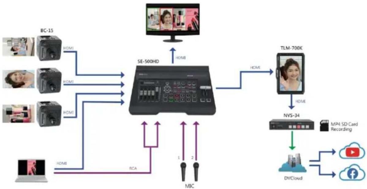
flowchart
graph TD
    A["BC-15"] -->|HDMI| B["SE-500HD"]
    C["BC-15"] -->|HDMI| B
    D["BC-15"] -->|HDMI| B
    E["BC-15"] -->|HDMI| B
    F["BC-15"] -->|HDMI| B
    G["BC-15"] -->|HDMI| B
    H["Computer"] -->|HDMI| B
    I["HDMI"] -->|RCA| B
    J["MIC"] -->|1 2| B
    K["TLM-700K"] -->|HDMI| B
    L["NVS-34"] -->|HDMI| B
    M["MP4 SD Card Recording"] --> N["DVC Cloud"]
    O["YouTube"] --> P["Cloud"]
    Q["Facebook"] --> R["Cloud"]
    B --> S["+ HDMI"]
    B --> T["+ HDMI"]
    B --> U["+ HDMI"]
2 Connections and Control
In this section, we will show you how you can operate the device as well as the device setup.
2.1 Front Panel
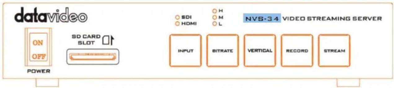

Power Switch
Turn on/off the device.
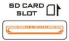
SD Card Slot
The SD Card Slot allows insertion of an SD Card for video recording.
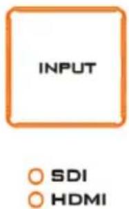
INPUT Button
Press the INPUT button to select between SDI and HDMI input sources. The button is always in solid white.
The activated input source will be indicated by the corresponding LED.
• Green: Input source activated
- Off: Input source deactivated
Note: The Input button is disabled while streaming or recording is in progress.


BITRATE Button
Switch the stream/record bitrate mode using the BITRATE button; follow the steps outlined below:
- Push and hold one of the RECORD and STREAM buttons until the pushed button starts blinking red.
- As soon as the pushed RECORD or STREAM button is released, the BITRATE button will turn solid red.
- While the BITRATE button stays solid red, push it to switch between different bitrate modes (H, M or L). Please note that the BITRATE button will return to solid white after a few seconds if button push is not sensed.
- To exit, push the the RECORD or STREAM button again.
Note: The system will return to the previous setting if the BITRATE button is not pushed. The default bitrate is M.
H/M/L LED Indicators
ON (Green): Bitrate mode enabled
OFF: Bitrate mode disabled

RECORD Button
The RECORD button activates and deactivates the RECORD Only mode; follow the steps outlined below:
Start recording
- When idle, the RECORD button is solid white.
- Press and hold the RECORD button for approximately 2 seconds.
- When the record function is activating, the RECORD button turns from solid white, then blinking red and finally to solid red.
- When the RECORD button turns solid red, this indicates that the record function has been successfully activated.
Stop recording
- While recording, the RECORD button is solid red.
- Press and hold the RECORD button for approximately 2 seconds.
- When the record function is terminating, the RECORD button turns from solid red, then blinking red and finally to solid white.
- When the RECORD button turns solid white, this indicates that the record function has been successfully terminated.
STREAM Button
The STREAM button activates and deactivates the STREAM Only mode; follow the steps outlined below:
Start streaming
- When idle, the STREAM button is solid white.
- Press and hold the STREAM button for approximately 2 seconds.
- When the stream function is activating, the STREAM button turns from solid white, then blinking red and finally to solid red.
- When the STREAM button turns solid red, this indicates that the record function has been successfully activated.
Stop streaming
• While streaming, the STREAM button is solid red.
- Press and hold the STREAM button for approximately 2 seconds.
- When the stream function is terminating, the STREAM button turns from solid red, then blinking red and finally to solid white.
- When the STREAM button turns solid white, this indicates that the stream function has been successfully terminated.

Vertical Button
Press the Vertical button to switch video orientation between Portrait and Landscape. See Section 3.4 for details.
Note: You can also switch video orientation via web user interface; see descriptions of the Vertical page for details.
2.2 Rear Panel
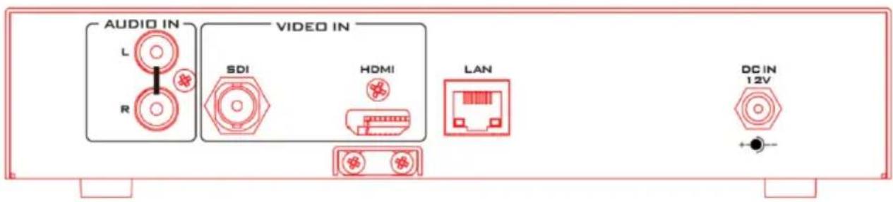
Audio Input
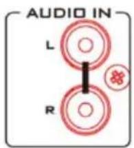
RCA Unbalanced Audio Input
Connect an unbalanced stereo audio source for streaming and recording.
Video Input
HDMI

HDMI Input
Connect an HDMI video source.
SDI

SDI Input
Connect an SDI video source.
Network
LAN
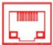
LAN
The LAN port connects the device to the Internet via an Ethernet cable.
Power
DC IN
12V

DC IN 12V
DC in socket connects the supplied 12V PSU. The connection can be secured by screwing the outer fastening ring of the DC In plug to the socket.

3 Video Streaming
In this section, we will show you how to set up and start your video streams.
3.1 Streaming Network Connection and Device Search
Let's first detail how to connect the NVS-34 to a network with or without a DHCP server, and acquire the NVS-34's IP address.
Note: The device is DHCP enabled by default.
Connecting to a DHCP Network (DHCP Mode)
Follow the procedure below to scan your DHCP network for connected NVS-34 devices.
Note: The NVS-34 will be automatically assigned an IP address upon connection to the DHCP network.
- Connect the NVS-34's LAN port to the network via an Ethernet cable.
- Turn on the NVS-34's power, which should boot up the device in DHCP mode by default.
- On your laptop, download the free IP Finder utility program from the product page https://www.datavideo.com/product/NVS-34.
- Connect the laptop to the same network that the NVS-34 is connected to and double click the IP Finder utility program icon.
- On the IP finder interface, click the SCAN button to start searching for connected devices.
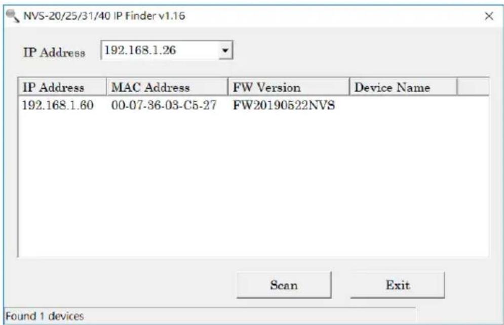

Connecting to a NON-DHCP Network (Static IP)
Upon connection to a non-DHCP network, the NVS-34 will not be assigned of any IP addresses. As such it is recommended that you manually assign a fixed IP address to the device or use the default IP address (192.168.1.200).
Fixed IP is primarily used in point-to-point connection, such as directly connecting the PC to the NVS-34. In a non-DHCP environment, the NVS-34 only works in fixed IP mode. To set the NVS-34 to a fixed IP or the default IP, please follow the steps outlined below:
- Connect the NVS-34's LAN port to the network via an Ethernet cable.
- Turn on the NVS-34's power, which should boot up the device in DHCP mode by default.
- Search for the NVS-34 device according to the method detailed in the previous DHCP section. Once found, log in to the user interface on the web browser.
- Open the system page by clicking the "System" tab on the home of the user interface.
- In the "Network Setting" pane, disable the DHCP mode.
- You will then be allowed to manually enter the static IP address once the DHCP mode is disabled. The default static IP is 192.168.1.200 or you can also enter an IP of your preference. The subnet mask and default gateway are 255.255.255.0 and 192.168.1.254 respectively.
Device Reset
In Fixed IP mode, if you forget or lose the IP address, do the following to reset the device settings.
- Power cycle NVS-34.
- During device bootup, the BITRATE, VERTICAL, RECORD and STREAM buttons should illuminate solid red.
- The device bootup should be complete approximately after 30 seconds and the BITRATE, VERTICAL, RECORD and STREAM buttons will turn solid white.
- Simultaneously press and hold the RECORD and STREAM buttons until the BITRATE, VERTICAL, RECORD and STREAM buttons turn red.
- Wait for about 5 seconds then release the RECORD and STREAM buttons and the BITRATE, VERTICAL, RECORD and STREAM buttons should start blinking red.

- The reset is complete as soon as you see the BITRATE, VERTICAL, RECORD and STREAM buttons illuminating solid white.
- The device's network settings should now be the default DHCP mode.
- Connect the device to a DHCP network and use the IP finder to scan for the device.
Troubleshooting the Network Connection
Connect the NVS-34 to the network and open the IP Finder utility program. Scan for the device. If not found, it is possible that your network is not assigning IP addresses.
Reasons of this are outlined as follows:
- Router or DHCP server is not responding to the device's request.
- New devices are blocked by the network administrator.
- Anti-virus software or the firewall blocks the communication.
Solve the problem by attempting the following:
- Turn off the router, wait for 10 seconds then turn on the router again.
- Reset the NVS-34 to the factory defaults (see the previous section for device reset).
If the problem still persists, try the following:
- Temporarily shut down the anti-virus software or firewall.
- Make sure no other devices are connected to the LAN (wired or wireless) because this may result in IP conflicts.
Advanced Troubleshooting
If you still are unable to connect, try the following:
- Use the ARP table to search for the device's MAC address which can be found on the print label at the bottom of your NVS-34.
- MAC address starts with 00:07:36:03:xx:xx.
- On the command prompt (terminal on MAC OS), enter "arp -a" then press enter key to display an ARP list. See if the NVS-34 is successfully connected to the network.
- Execute services.msc, and on the right column of the "Services" window, locate "DHCP Client" then click "Restart".
- On the command prompt, enter ipconfig/flushdns followed by ipconfig/release and ipconfig/renew.
3.2 Web User Interface
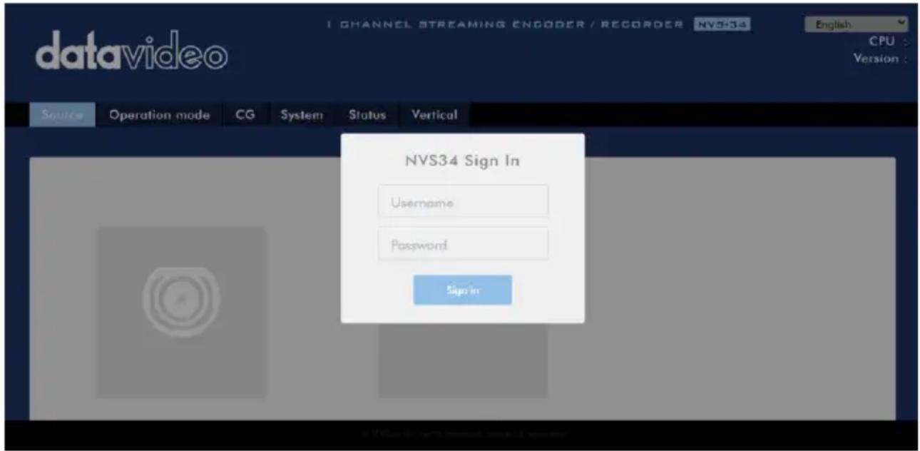
By now, we have obtained the IP address of the NVS-34. To open the web user interface, either double click the device's IP on the IP finder or enter the device's IP into the address bar of a web browser then hit the ENTER button. Log in by entering the username as well as the password into the pop-up dialogue box as shown below.
- Username: admin
- Password: 000000
Click OK to log in.
Source
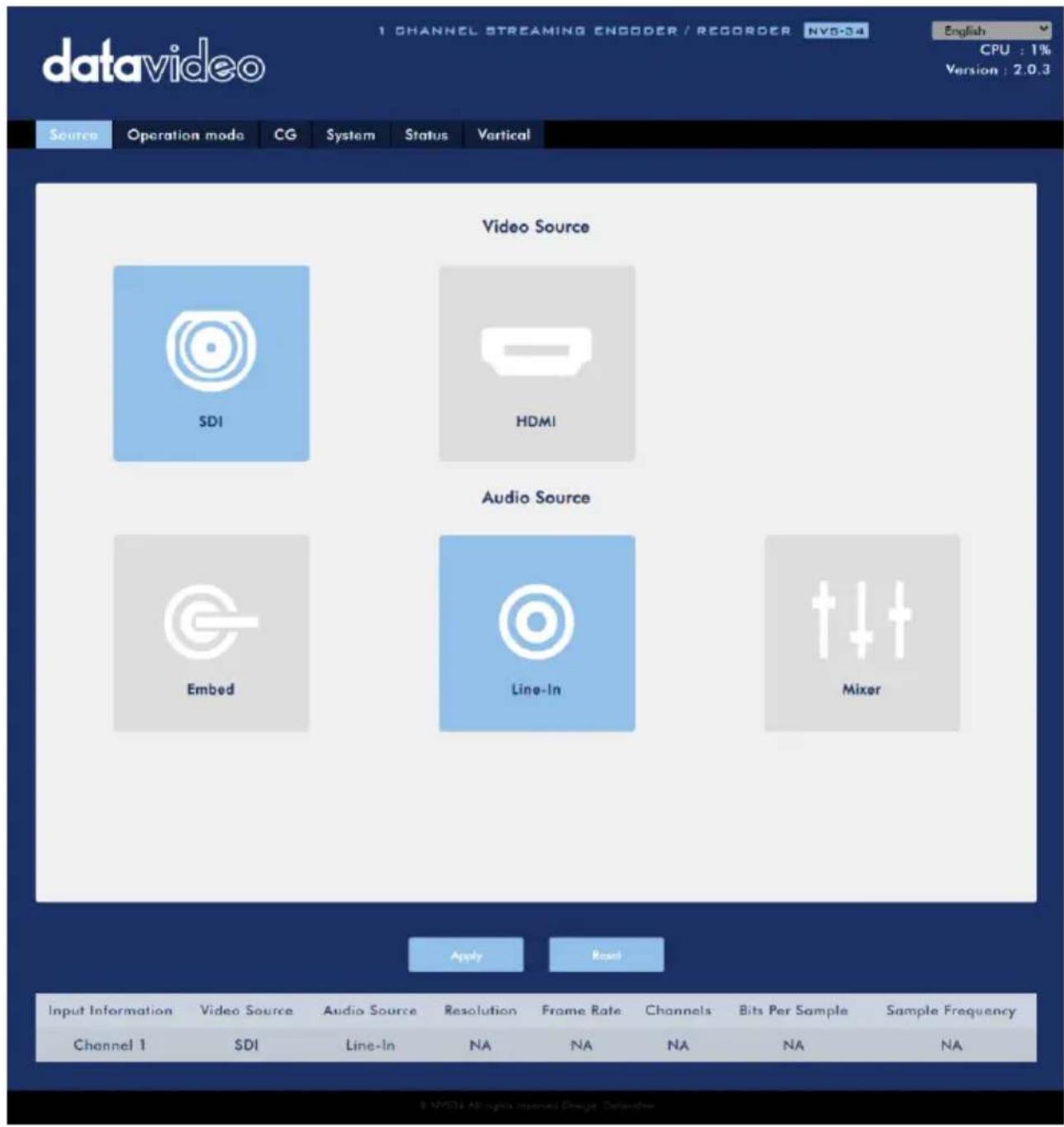
You will see the Source page immediately after logging into the web UI, on which first select the video source, SDI or HDMI.
If you've selected SDI, you only need to select the audio source next. The available audio source options are Embed, Line-In and Mixer. Descriptions of which are outlined as follows:
- Embed: SDI embedded audio
• Line-In: External audio from RCA AUDIO IN jacks - Mixer: A mix of SDI and HDMI embedded audio as well as RCA AUDIO IN
If you've selected HDMI, you will be allowed to adjust the source video's brightness, contrast, hue and saturation by dragging the corresponding sliders as shown in the diagram below. After that, select your audio sources. You may choose to output HDMI embedded audio (Embed), external audio from RCA AUDIO IN jacks (Line-In), or a mix of SDI and HDMI embedded audio as well as RCA AUDIO IN (Mixer).
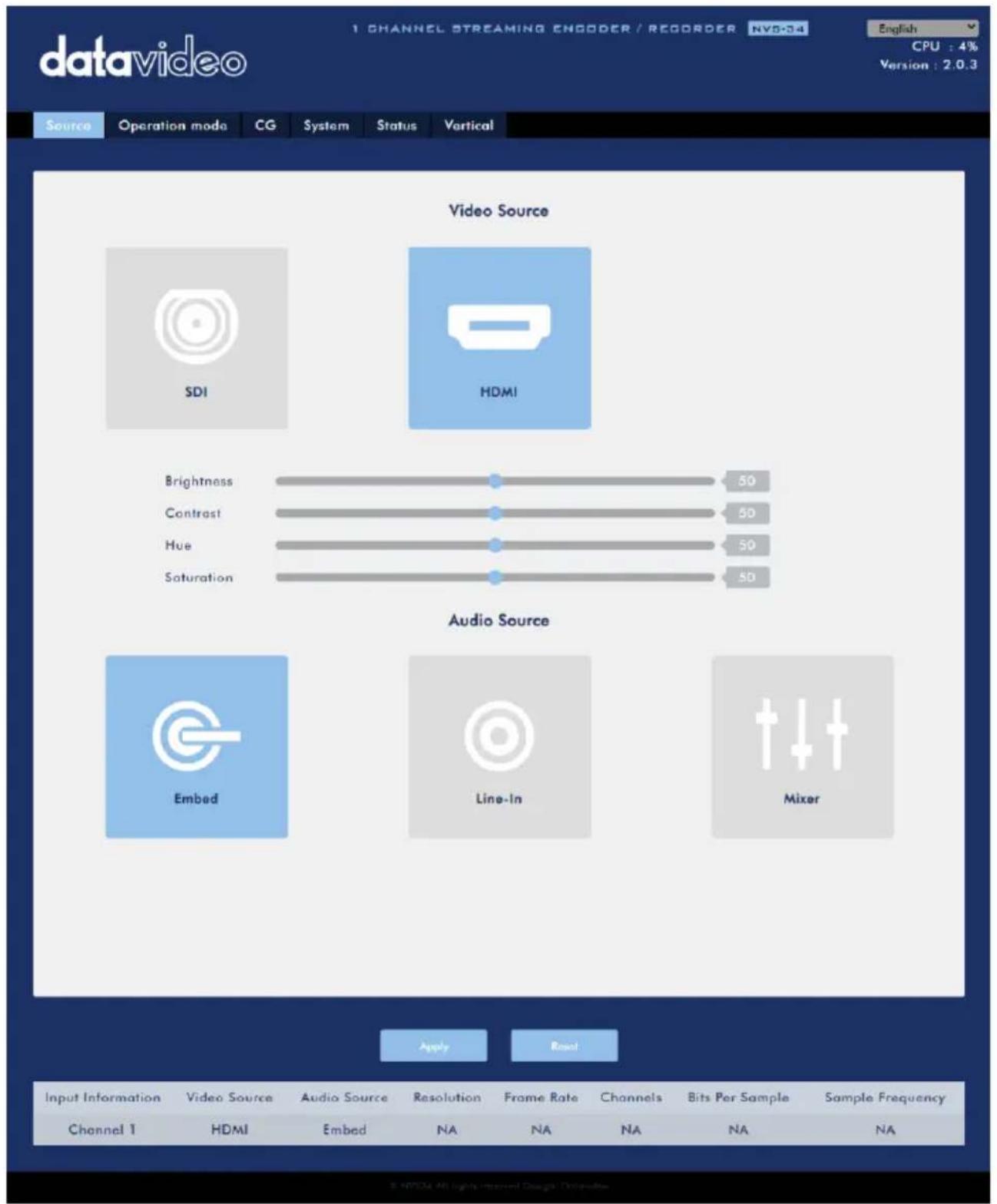
At the bottom of the page, you will be able to view video and audio source information such as Input Information, Video Source, Audio Source, Resolution, Frame Rate, Channels, Bits Per Sample and Sample Frequency.
Note: The NVS-34 web UI does not update automatically so to learn the latest device status, please refresh the page manually.
While monitoring streaming and recording, please update the page periodically regardless of how you operate the device (using the device's physical buttons only or using the device's physical buttons along with the web UI). This ensures the page is always displaying the most up-to-date information.
Operation Mode
Click the Operation Mode tab on the tool bar to open the operation mode configuration page on which the user will be allowed to customize various stream and record settings.
The NVS-34 offers the following operation modes:
- Stream
- Record
which will be discussed in detail in this section.
Stream Mode
The NVS-34 has two stream engines allowing you to stream to two different destinations over multiple protocols such as RTSP, RTMP, TS and HLS. See Section 3.3 for instructions on each individual stream setup.
The configurable stream video settings are Encoder Source, Stream Type, Resolution, Frame Rate, Profile, Level, Entropy, GOP and Video Bitrate (bps) which will be described later in this section.
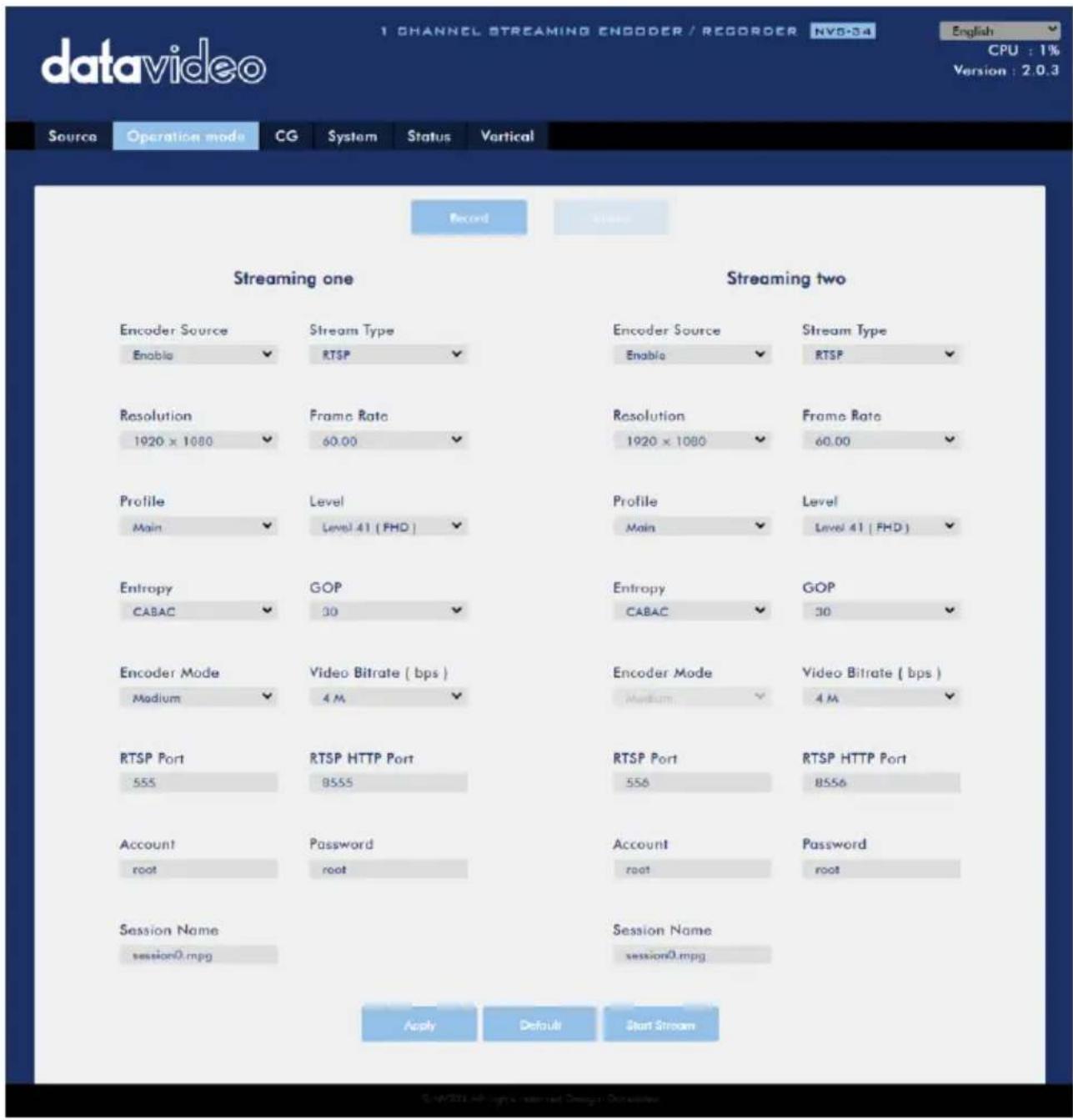
Note that once your video streams are set up, click "Apply" button to apply the new stream settings. Click "Start Stream" to open the stream and "Stop Stream" to end the stream. To reset, simply click the default button.
Next, we will discuss the stream setting options in greater detail.
Encoder Source
This option allows you to enable the stream encoder for configurations of various parameters. If the stream encoder is not needed, disable this option.
Stream Type
The NVS-34 offers the user four stream types which are RTSP, RTMP, TS, and HLS. Parameters of each individual protocol will be briefly described below.
RTSP (Real Time Streaming Protocol)
- RTSP Port: The RTSP port number ranges from 554 to 562 and is 554 by default.
- RTSP HTTP Port: The RTSP HTTP port number ranges from 8553 to 8563 and is 8554 by default.
- Account / Password: The RTSP streaming account credentials which are root/root by default.
- Session Name: The default RTSP session name is session0.mgp.
RTMP (Real-Time Messaging Protocol)
-
RTMP URL: Enter an RTMP URL obtained from any live streaming platform such as Youtube.
Note: The NVS-34 supports RTMP Publish only and not RTMP Local. -
Stream Name: Enter a stream name or key from any live streaming platform such as Youtube.
- Account / Password: Enter the account name and the password of your RTMP platform account.
TS (Transport Stream)
- TS URL: Enter a URL for your transport stream.
Please note that when streaming, the NVS-34 converts video into data, which are sent across an IP network. High bitrates consume more bandwidth across the IP network. In a gigabit office LAN, high bitrate may not be a concern and Speed/Bandwidth is therefore not a limitation in an NVS-34 application environment.
If your available bandwidth is limited, you should reduce both your resolution and your bitrate accordingly. A good rule of thumb is for the bitrate of your stream to use no more than 50% of your available upload bandwidth capacity on a dedicated line. For example, if the result you get from a speed test shows that you have 2Mbps of upload speed available, your video bitrate should not exceed 1Mbps.
Resolution
The first step of encoder setup is to adjust the image size. It is best to either match your original video source or scale it down. For example, capture at HD 720 and stream at HD 720, or capture at HD 720 and stream at 540 (high).
You should never be scaling up and streaming at a higher resolution than your original video source. For example, it does not make sense to capture at 720 and stream at 1080. Note that you will also have no gain in quality and you are using more bandwidth than is necessary for your viewers.
You should also be aware that higher resolutions require greater processing power to encode the stream. Attempting too high of a resolution on too little processing power can result in degraded image quality and corrupted or interrupted streams or recordings.
Resolutions available for the stream encoder are listed as follows:
- 1080x1920
- 720x1280
- 576x720
- 480x720
- 480x640
- 240x320
Frame Rate
Select a frame rate from the drop-down menu for video streaming. Note that frame rates should always match the frame rate of the video source.
• 60.00
• 50.00
• 30.00
• 25.00
• 20.00
• 15.00
Video Bitrate (bps)
The bitrate of the video specifies the amount of information stored in the video. The higher the bitrate is, the clearer the video is. However, when choosing your encoder settings for streaming, you should first check your available upload bandwidth. A good rule of thumb is for the bitrate of your stream to use no more than 50% of your
available upload bandwidth capacity on a DEDICATED line. For example, if the result you get from a speed test shows that you have 2Mbps of upload speed available, your combined audio and video bitrate should not exceed 1Mbps.
Usually high bitrate means good image quality; however, there are also exceptions. For example, SD video may appear acceptable at 1000 Kbps (1M) but HD video is unacceptable at 1000 Kbps.
Available video bitrates are listed as follows:
The Encoder Mode sets the video bitrate mode for your video stream. The available modes are listed as follows:
• High (8M)
- Medium (4M)
- Low (2M)
Tip: You can also switch between different bitrate modes by pressing the Bitrate button on the front panel. See Section 3.4 for details.
Profile
Profile sets the H.264 encoding profile for your stream. The available options are Baseline, Main, and High. Typically, High profile provides the best image quality and is suitable in most instances. However, depending on the decoder used when viewing the stream, such as with mobiles devices, a Main or Baseline profile may be required.
- High
- Main
- Baseline
Level
Levels specify the size of the video a decoder must be able to handle. They specify a maximum bit-rate for the video and a maximum number of macroblocks per second. Level numbers range from 1 to 5 with intermediate steps (e.g., 1.1, 1.2, 1.3 and etc). The table below provides a summary of maximum parameters supported by each H.264/AVC level.
| Level ID | Max. Video Bitrate in kbits/s | Max Frame Size in macroblocks | Max decoding speed in macroblocks per second | Resolution, Frame Rate (Max Stored Frames) |
| 1.0 | 64 | 99 | 1485 | 128×96@30.9 (8)176×144@15.0 (4) |
| 1b | 128 | 99 | 1485 | 128×96@30.9 (8)176×144@15.0 (4) |
| 1.1 | 192 | 396 | 3000 | 176×144@30.3 (9)320×240@10.0 (3)352×288@7.5 (2) |
| 1.2 | 384 | 396 | 6000 | 320×240@20.0 (7)352×288@15.2 (6) |
| 1.3 | 768 | 396 | 11880 | 320×240@36.0 (7)352×288@30.0 (6) |
| 2.0 | 2000 | 396 | 11880 | 320×240@36.0 (7)352×288@30.0 (6) |
| 2.1 | 4000 | 792 | 19800 | 352×480@30.0 (7)352×576@25.0 (6) |
| 2.2 (SD) | 4000 | 1620 | 20250 | 352×480@30.7 (12)352×576@25.6 (10)720×480@15.0 (6)720×576@12.5 (5) |
| 3.0 | 10000 | 1620 | 40500 | 352×480@61.4 (12)352×576@51.1 (10)720×480@30.0 (6)720×576@25.0 (5) |
| 3.1 | 14000 | 3600 | 108000 | 720×480@80.0 (13)720×576@66.7 (11)1,280×720@30.0 (5) |
| 3.2 (HD) | 20000 | 5120 | 216000 | 1,280×720@60.0 (5)1,280×1,024@42.2 (4) |
| 4.0 | 20000 | 8192 | 245760 | 1,280×720@68.3 (9)1,920×1,080@30.1 (4)2,048×1,024@30.0 (4) |
| 4.1 (FHD) | 50000 | 8192 | 245760 | 1,280×720@68.3 (9)1,920×1,080@30.1 (4)2,048×1,024@30.0 (4) |
Entropy
There are two coding options available for generating H.264 content:
- CAVLC (Context-Adaptive Variable Length Coding)
• CABAC (Context-based Adaptive Binary Arithmetic Coding)
CABAC encoding provides a 7-10% quality improvement over CAVLC but requires an extra 10-15% CPU. CABAC encoding is only available in H.264 Profiles Main & High. When targeting at low-powered devices, such as older cell phones and tablets, we recommend the Baseline Profile that uses CAVLC which requires less computing power.
GOP
GOP pattern with longer GOP length encodes video very efficiently. Shorter GOP lengths usually work better with video that has quick movements, but they do not compress the data rate as much. Depending on your applications, you can select 16 GOP sizes ranging from 1 to 255.
The NVS-34's record engine allows you to record your program on the SD card. See Section 5 for a list of recommended SD cards. The record parameters shown in the diagram below will be discussed in detail in this section.
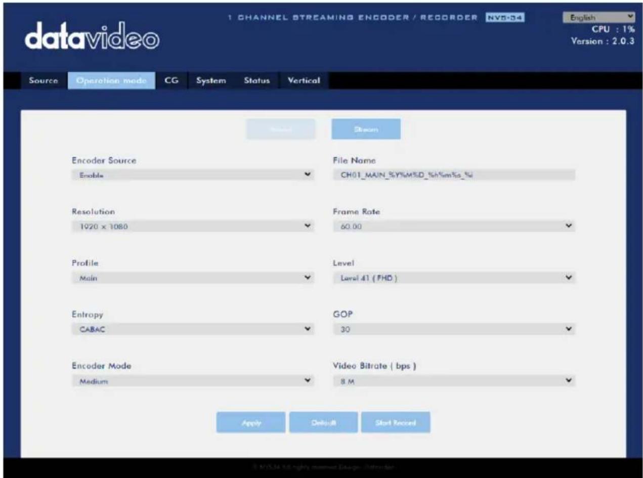
Note that after you've configured the record settings, click "Apply" to apply the new record settings. Click "Start Record" to start recording and "Stop Record" to end recording. To reset, simply click the default button.
Encoder Source
This option allows you to enable the record engine for configurations of various recorder parameters. If the recorder is not needed, disable this option.
File Name
Enter the name of your record file.
Resolution
Recording resolution is the number of pixels (dots) used to create an image. Higher resolutions use more pixels to create an image. This means that greater amounts of detail can be expressed in the image, but larger files sizes and a greater amount of storage (i.e. hard drive space) are required to save the images or video.
Resolutions available for your recorder are listed as follows:
- 1080x1920
- 720x1280
- 576x720
- 480x720
- 480x640
- 240x320
Frame Rate
Select a frame rate from the drop-down menu for video recording.
- 60.00
• 50.00
• 30.00
• 25.00
• 20.00
• 15.00
Frame rate greatly impacts the style and viewing experience of a video. Different frame rates yield different viewing experiences, and choosing a frame rate often means choosing between things such as how realistic you want your video to look, or whether or not you plan to use techniques such as slow motion or motion blur effects.
Below is a list of common options for different applications:
- 24fps – This is the standard for movies and TV shows, and it was determined to be the minimum speed needed to capture video while still maintaining realistic motion.
- 30fps – Videos with a lot of motion, such as sports, will often benefit from the extra frames per second.
- 60+fps – Anything higher than 30fps is mainly used to create slow motion video or to record video game footage.
Video Bitrate (bps)
The bitrate of the video specifies the amount of information stored in the video. The higher the bitrate is, the clearer the video is.
Available video bitrates are listed as follows:
Recommended video bitrates
• 720P or lower - 8 - 10 mbps
• 1080P or higher – 15 mbps or higher
Encoder Mode
The Encoder Mode sets the video bitrate mode for your recording. The available modes are listed as follows:
- High (8M)
- Medium (4M)
- Low (2M)
Tip: You can also switch between different bitrate modes by pressing the Bitrate button on the front panel. See Section 3.4 for details.
Profile
Profile sets the H.264 encoding profile for your recorder. The available options are Baseline, Main, and High. Typically, High profile provides the best image quality and
is suitable in most instances. However, depending on the decoder used when viewing the recording, a Main or Baseline profile may be required.
- High
- Main
- Baseline
Level
Levels specify the size of the video a decoder must be able to handle. They specify a maximum bit-rate for the video and a maximum number of macroblocks per second. Level numbers range from 1 to 5 with intermediate steps (e.g., 1.1, 1.2, 1.3 and etc). The table below provides a summary of maximum parameters supported by each H.264/AVC level.
| Level ID | Max. Video Bitrate in kbits/s | Max Frame Size in macroblocks | Max decoding speed in macroblocks per second | Resolution, Frame Rate (Max Stored Frames) |
| 1.0 | 64 | 99 | 1485 | 128×96@30.9 (8)176×144@15.0 (4) |
| 1b | 128 | 99 | 1485 | 128×96@30.9 (8)176×144@15.0 (4) |
| 1.1 | 192 | 396 | 3000 | 176×144@30.3 (9)320×240@10.0 (3)352×288@7.5 (2) |
| 1.2 | 384 | 396 | 6000 | 320×240@20.0 (7)352×288@15.2 (6) |
| 1.3 | 768 | 396 | 11880 | 320×240@36.0 (7)352×288@30.0 (6) |
| 2.0 | 2000 | 396 | 11880 | 320×240@36.0 (7)352×288@30.0 (6) |
| 2.1 | 4000 | 792 | 19800 | 352×480@30.0 (7)352×576@25.0 (6) |
| 2.2 (SD) | 4000 | 1620 | 20250 | 352×480@30.7 (12)352×576@25.6 (10)720×480@15.0 (6)720×576@12.5 (5) |
| 3.0 | 10000 | 1620 | 40500 | 352×480@61.4 (12)352×576@51.1 (10)720×480@30.0 (6)720×576@25.0 (5) |
| 3.1 | 14000 | 3600 | 108000 | 720×480@80.0 (13)720×576@66.7 (11)1,280×720@30.0 (5) |
| 3.2 (HD) | 20000 | 5120 | 216000 | 1,280×720@60.0 (5)1,280×1,024@42.2 (4) |
| 4.0 | 20000 | 8192 | 245760 | 1,280×720@68.3 (9)1,920×1,080@30.1 (4)2,048×1,024@30.0 (4) |
| 4.1 (FHD) | 50000 | 8192 | 245760 | 1,280×720@68.3 (9)1,920×1,080@30.1 (4)2,048×1,024@30.0 (4) |
Entropy
There are two coding options available for generating H.264 content:
- CAVLC (Context-Adaptive Variable Length Coding)
• CABAC (Context-based Adaptive Binary Arithmetic Coding)
CABAC encoding provides a 7-10% quality improvement over CAVLC but requires an extra 10-15% CPU. CABAC encoding is only available in H.264 Profiles Main & High. When targeting at low-powered devices, such as older cell phones and tablets, we recommend the Baseline Profile that uses CAVLC which requires less computing power.
GOP
GOP pattern with longer GOP length encodes video very efficiently. Shorter GOP lengths usually work better with video that has quick movements, but they do not compress the data rate as much. Depending on your applications, you can select 16 GOP sizes ranging from 1 to 255.
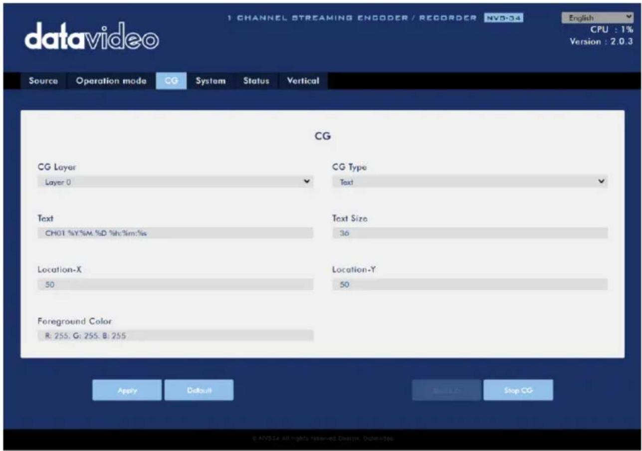
The CG function allows the user to place a textual or picture layer on top of the video. The CG settings are shown in the diagram below.
CG Layer
You are allowed to toggle the CG text or picture between four layers, from layer 0 to layer 3.
CG Type
You may select to place a text (Text) or graphic (Picture) CG object on your video from the drop-down menu.
Text
After setting the CG type to Text, you will be allowed to enter the text that you want to place on the video.
Enter CG text in the Text field and CG text font size in the Text Size field.
| Text | Text Size |
| CH01 %Y.%M.%D %h:%m:%s | 36 |
Picture
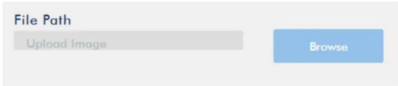
If you set the CG Type to Picture, you will be required to select a picture file from your local hard disk. Click Browse to browse the hard drive for your graphic CG file.
Location-X
Enter the x-coordinate that determines the horizontal location of the CG object overlaid.
Location-Y
Enter the y-coordinate that determines the vertical location of the CG object overlaid.
Foreground Color
You may either enter the RGB values or select a color from the color spectrum to set the foreground color. Then fine tune the selected color by dragging the circle cursor on the palette. Click the color wheel button at the bottom right corner to confirm the selection.
Foreground Color
R: 255. G: 255. B: 255
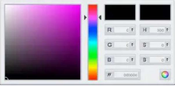
R: Red H: Hue
G: Green S: Saturation
B: Blue B: Brightness
System
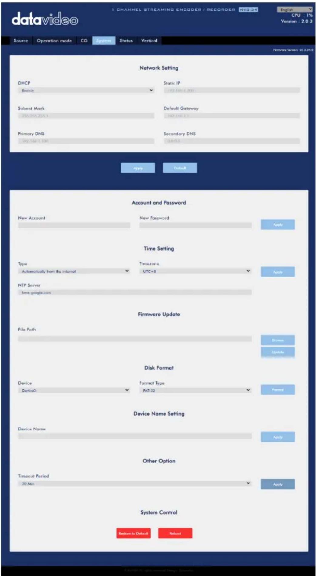
The system page allows the user to configure several network and system related settings.
The network settings are DHCP enable/disable, static IP address, subnet mask, default gateway, primary and secondary DNS, and etc.
The system settings are account credentials, time settings, firmware update, disk format and device name.
The system page is shown in the diagram below.
Network Setting
In network settings, you can either manually enter the IP address or set the device to DHCP mode which allows the router to automatically assign the IP address to the NVS-34.
DHCP
In DHCP mode, the router automatically assigns the IP address to the device. If you want to manually configure the network settings, disable this option.
Static IP Address
If the DHCP is disabled, the static IP field will be activated for the user to manually enter the IP address. The static IP address is 192.168.1.200 by default.
Tip: If you do not know the device's IP address, you can always reset the device to restore default network settings. See Device Reset for instructions.
Subnet Mask
Static IP address mode requires the subnet mask, which is 255.255.255.0 by default.
Default Gateway
Static IP address mode requires the default gateway, which is 192.168.1.254 by default.
Primary DNS (Optional)
Primary DNS is required in static IP mode only but is optional.
Secondary DNS (Optional)
Secondary DNS is required in static IP mode only but is optional.
Account and Password
Set the NVS-34's account name and password here. Click Apply to save the new login credentials.
Time Setting
In time setting, you are allowed to select the reference time source for the NVS-34.
Type
In this drop-down menu, you can either select to allow the device to retrieve the time automatically from the Network Time Protocol (NTP) server by selecting "Automatically from the Internet" or locally by selecting "Manual".
NTP Server
If you've selected "Automatically from the Internet," you will need to enter the NTP server address here. An example of the NTP server address is time.google.com.
Manual
If you've selected "Manual", the Date and Time fields will appear showing the device's system date and time values. A calendar will appear after the Date field is clicked. Simply click a day to set the date. Enter the time in the Time field.
| May 2020 | ||||||
| Su | Mo | Tu | We | Th | Fr | Sa |
| 1 | 2 | |||||
| 3 | 4 | 5 | 6 | 7 | 8 | 9 |
| 10 | 11 | 12 | 13 | 14 | 15 | 16 |
| 17 | 18 | 19 | 20 | 21 | 22 | 23 |
| 24 | 25 | 26 | 27 | 28 | 29 | 30 |
| 31 | ||||||
Time Zone
Click the drop-down menu to select a time zone for your device.
After you've configured the time settings, click Apply to save the new settings.
Firmware Update
Click Browse to search for the latest firmware file saved on the PC's hard disk. After the latest firmware file is uploaded, click Update to start the firmware update.
Disk Format
In this pane, you will be allowed to view the SD card information and format the SD card to one of the format types listed as follows:
- FAT-32
- NTFS
- EXFAT
Click Format to start formatting.
Device Name Setting
Enter a name for this device and click Apply to save the name.
Other Option
Timeout Period
This sets the timeout period for the current login. See below for available options.
- 20 Min
- 120 Min
• 1 Day - 7 Day
- Never
System Control
Restore to Default
Click to restore the system's default settings.
System Reboot
Click to reboot the NVS-34.
Status
The status page shows Record, Stream and Disk information as depicted in the diagram below.
Note: The NVS-34 web UI does not update automatically so to learn the latest device status, please refresh the page manually.
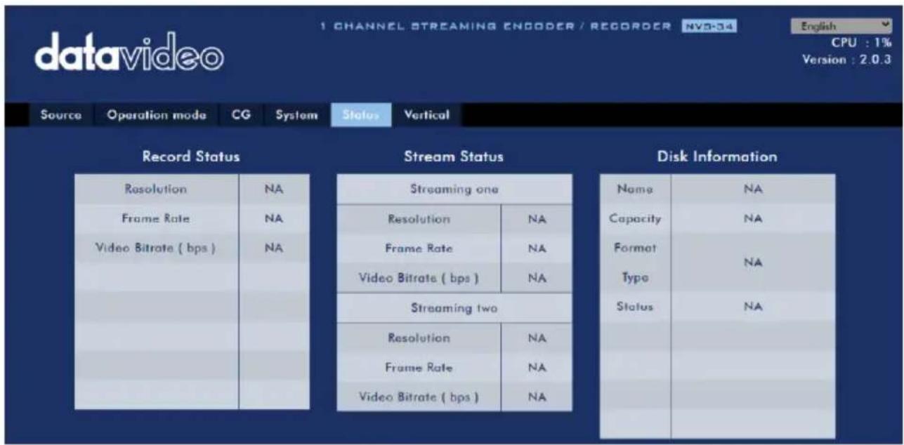
While monitoring streaming and recording, please update the page periodically regardless of how you operate the device (using the device's physical buttons only or using the device's physical buttons along with the web UI). This ensures the page is always displaying the most up-to-date information.
Vertical
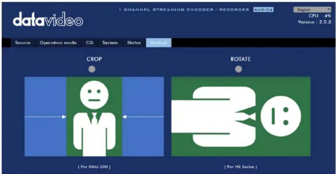
On this page, you will be able to change your stream video orientation.
- Crop allows 16:9 video output and left/right image crop.
- Rotate is designed for video production; if the camera is placed upside down, this mode will reverse it.
3.3 Operations
In this section, we will discuss how to customize your operation mode, how you can play the video via different streaming protocols and how to place texts on your video.
Video Streaming
The NVS-34 provides the user with different options for video streaming such as RTSP, TS, RTMP and HLS.
This section discusses settings of these options and how to stream your video using these methods.
RTSP/TS/HLS
In the RTSP/TS/HLS modes, the NVS-34 is a stream server allowing any client device to connect and playback your video stream. However, if you would like to stream to multiple client devices, we recommend using a separate media server to set up your streaming environment.

The following operation procedure uses VLC media player to playback video stream. If your PC or laptop does not have VLC media player installed, please visit VideoLAN's official homepage (https://www.videolan.org/) and download the installation file then install the program.
Follow the steps below to obtain the RTSP URL:
- On the web UI, click "Operation Mode" → "Stream" to open the stream settings page.
- Select RTSP from Stream Type drop-down menu.
Stream Type
RTSP

- Click the Start Stream button to generate the RTSP URL.
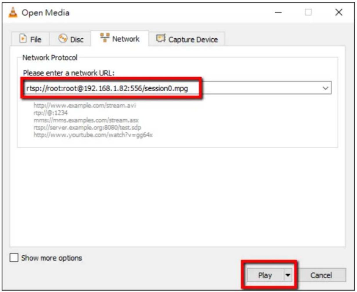
- Based on your settings, the device will automatically generate the RTSP URL rtsp://root:root@192.168.1.82:556/session0.mpg.
Play URL
rtsp://root:root@192.168.1.8;
- To view the RTSP video stream, enter the RTSP URL into the client device.
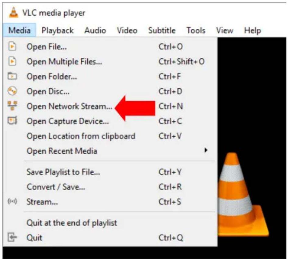
- Open VLC then click Open Network Stream (shown in the diagram below).
- As shown in the diagram below, enter the stream URL then click Play to start streaming.
Follow the steps below to obtain the TS URL:
- On the web UI, click "Operation Mode" "Stream" to open the stream settings page.
- Select TS from Stream Type drop-down menu.
Stream Type
TS

- Enter the TS URL. Note that the TS URL shown below is only for illustration purpose.
TS URL
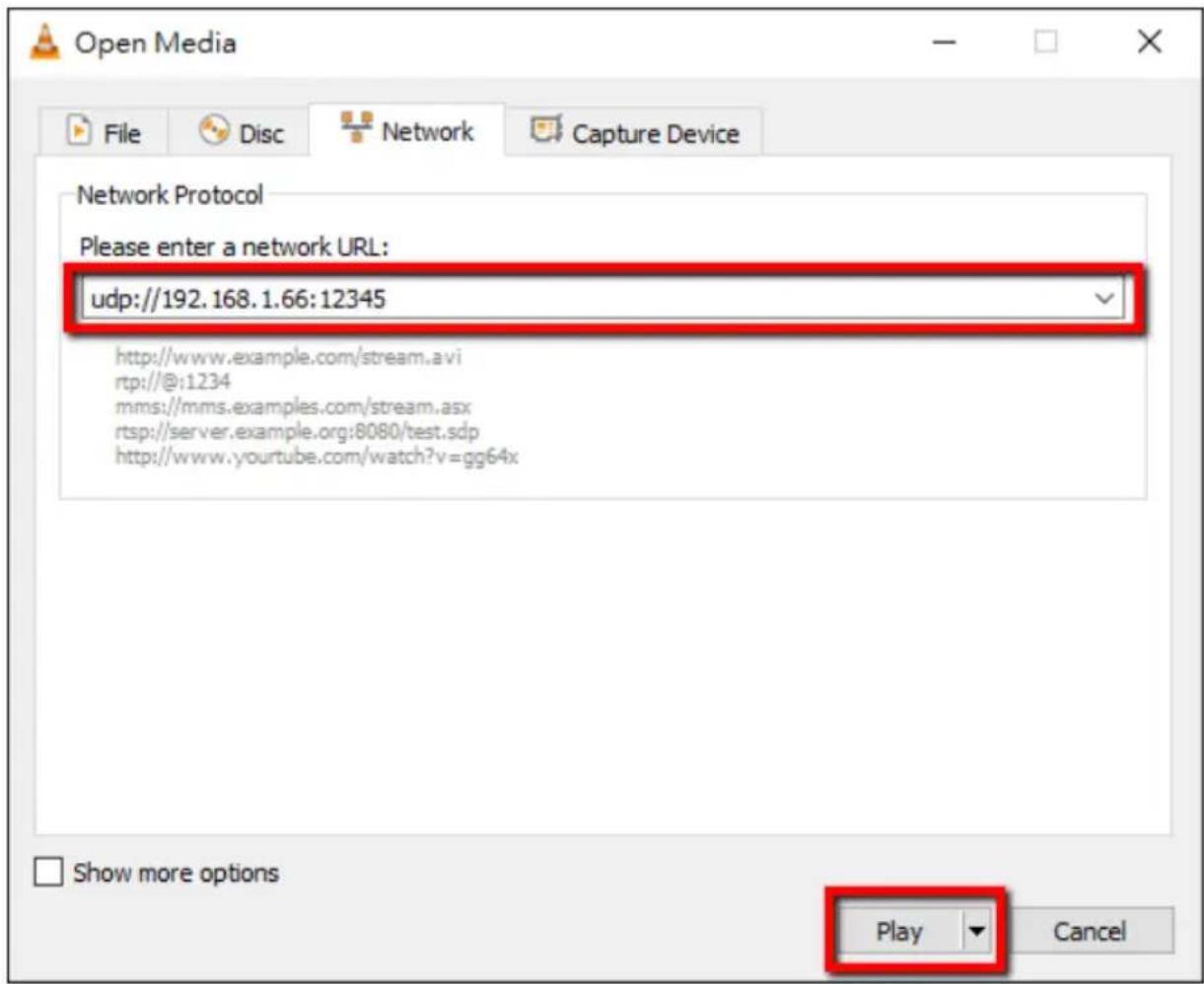
udp://192.168.1.66:12345
- Click the Start Stream button to start the stream.
Play URL
udp://192.168.1.66:12345
- Enter the TS play URL into the client device to which the video stream is delivered over TS protocol.
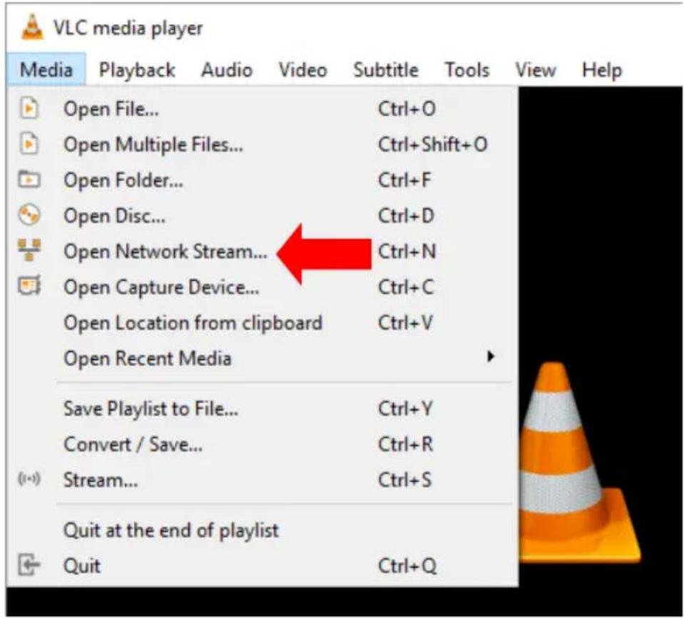
- On the computer, open VLC then click Open Network Stream (shown in the diagram below).
- As shown in the diagram below, enter the stream URL then click Play to start streaming.
Follow the steps below to obtain the HLS URL:
- On the web UI, click "Operation Mode" → "Stream" to open the stream settings page.
- Select HLS from Stream Type drop-down menu.
Stream Type
HLS

- Click the Start Stream button to start the stream.
Play URL
http://192.168.1.82/hls/2/ses
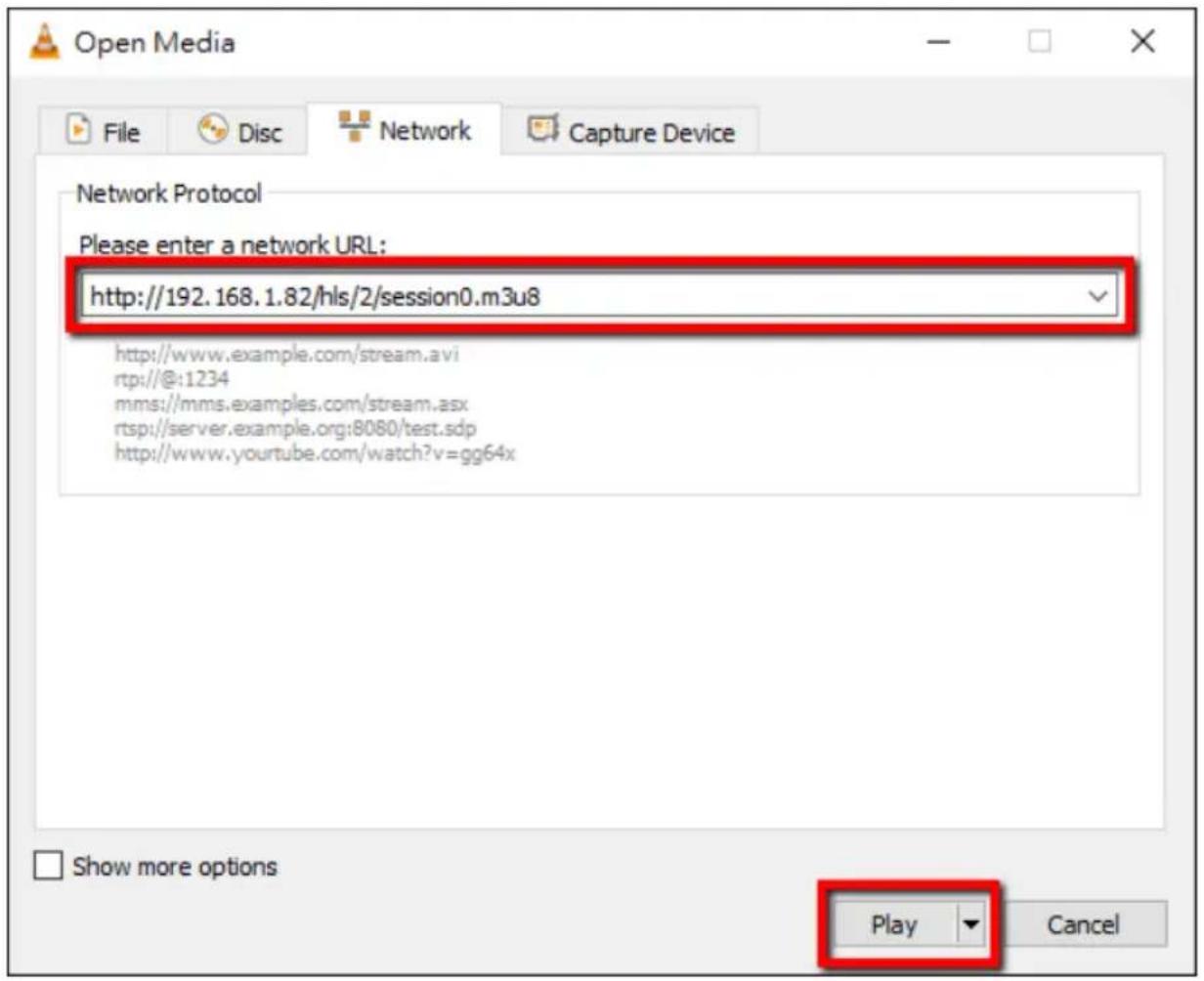
- Based on your settings, the device will automatically generate a .m3u8 stream
URL: http://192.168.1.82/hls/2/session0.m3u8
-
Enter the HLS URL into the client device.
-
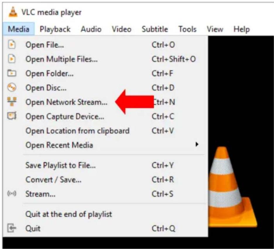
Open VLC then click Open Network Stream (shown in the diagram below).
- As shown in the diagram below, enter the stream URL then click Play to start streaming.
-
You can also play .m3u8 stream URL using the devices listed as follows:
-
iPhone, iPad and MacBook: Use Safari to open the .m3u8 stream URL.
- Windows 10: Use Microsoft Edge to open the .m3u8 stream URL.
RTMP
In RTMP mode, the NVS-34 can only send one data stream to one CDN or media server that supports the Real-Time Messaging Protocol (RTMP). An example of the RTMP media server is Youtube.
In the following section, we will show you how to set up an RTMP stream to Youtube. The step-by-step account setup is outlined as follows:
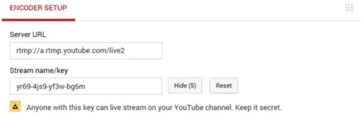
- First obtain Server URL and Stream name/key from Youtube.
-
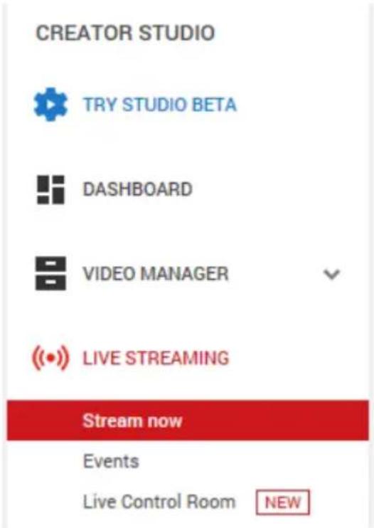
On the left column, locate and click "Stream now."
-
Open the Youtube Live Dashboard https://www.youtube.com/live_dashboard
- On the right, scroll down to the bottom where you will be able to find Server URL and Stream name/key.
- On the NVS-34, open the Stream operation mode page.
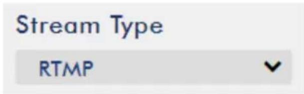
- Select RTMP from the Stream Type drop-down menu.
- Enter the Server URL (rtmp://a.rtmp.youtube.com/live2) obtained from the Youtube Live Streaming page into the RTMP URL field.
RTMP URL
ex: rImp://192.168.1.
- Enter the Stream name/key (yr69-4js9-yf3w-bg6m) obtained from the Youtube Live Streaming page into the StreamName field.
Stream Name
- As required by the live streaming channel, enter your Youtube account name and password into the Account and Password fields.
Account
Password
- Click the Start Stream button to start streaming the live video on the Youtube Live Streaming page. You should also see an RTMP URL generated.
Play URL
rtmp://a.rtmp.youtube
-
At this point, you should be able to view your stream video on Youtube.
-
To stop live streaming, simply click the Stop Stream button.
Text Overlay Video
The NVS-34 video streaming server not only allows you to stream and record your program, it also features a CG tool that is capable of overlaying text on the video currently being broadcast.
The CG settings page is shown below:
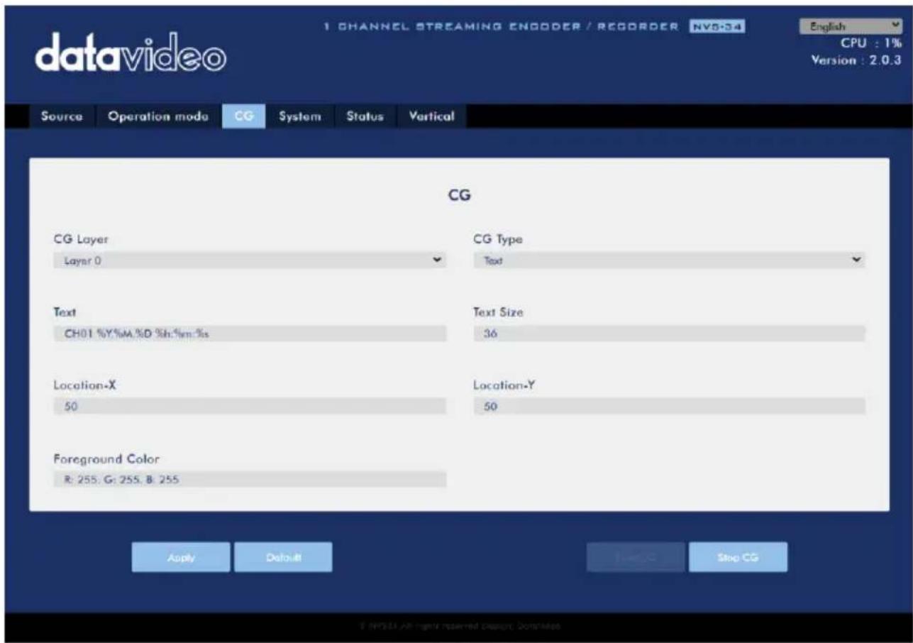
Follow the steps below to overlay text on the video:
- Open the CG settings page.
- Set the CG layer.
- Select the CG Type.
- If Text is selected, enter the overlay text in the Text field, otherwise browse for the picture file on the disk.
- Enter the X and Y coordinates to set the CG object position.
- If you have selected the picture CG, you will need to adjust the object's width and height as well.
- Set the foreground color.
- Click Apply button to save CG settings.
Note: Increasing the X coordinate moves the overlay text to the right and decreasing the X coordinate moves the overlay text to the left; increasing the Y coordinate moves the overlay text up and decreasing the Y coordinate moves the overlay text down.
3.4 Stream and Record Buttons
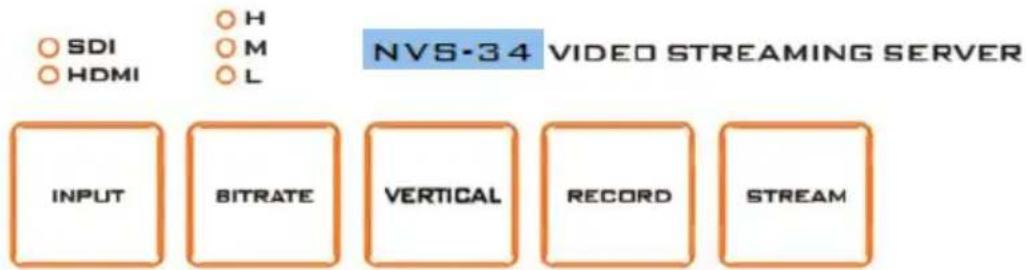
The INPUT, RECORD, STREAM, VERTICAL and BITRATE buttons on the front panel give the user certain controls of the record and stream functions. In this section, we will cover operations of these four buttons in detail.
Input Button
Press the INPUT button to select between SDI and HDMI input sources. The button is always in solid white.
The activated input source will be indicated by the LEDs above the button.
• Green: Input source activated
• Off: Input source deactivated
Note: The Input button is disabled while streaming or recording is in progress.
Record Button
Press the RECORD button to start/stop recording.
The table below summarizes the RECORD Button LED behaviors:
| RECORD Button | |
| Solid White | Record function in idle state |
| Blinking Red | Record function is activating or resetting |
| Solid Red | Record function activated |
Start recording
- When idle, the RECORD button is solid white.
-
Press and hold the RECORD button for approximately 2 seconds.
-
When the record function is activating, the RECORD button turns from solid white, then blinking red and finally to solid red.
- When the RECORD button is solid red, this indicates that the record function has been successfully activated.
Stop recording
• While recording, the RECORD button is solid red.
- Press and hold the RECORD button for approximately 2 seconds.
- When the record function is terminating, the RECORD button turns from solid red, then blinking red and finally to solid white.
- When the RECORD button is solid white, this indicates that the record function has been successfully terminated.
Stream Button
Press the STREAM button to start/stop streaming.
The table below summarizes the STREAM Button LED behaviors:
| STREAM Button | |
| Solid White | Stream function in idle state |
| Blinking Red | Stream function is activating or resetting |
| Solid Red | Stream function activated |
Start streaming
- When idle, the STREAM button is solid white.
- Press and hold the STREAM button for approximately 2 seconds.
- When the stream function is activating, the STREAM button turns from solid white, then blinking red and finally to solid red.
- When the STREAM button is solid red, this indicates that the record function has been successfully activated.
Stop streaming
• While streaming, the STREAM button is solid red.
- Press and hold the STREAM button for approximately 2 seconds.
- When the stream function is terminating, the STREAM button turns from solid red, then blinking red and finally to solid white.
- When the STREAM button is solid white, this indicates that the stream function has been successfully terminated.
Bitrate Button
Follow the steps below to switch the stream bitrate mode using the BITRATE button:
- Push and hold one of the RECORD and STREAM buttons until the pushed button starts blinking red.
- As soon as the pushed RECORD or STREAM button is released, the BITRATE button will turn solid red.
- While the BITRATE button stays solid red, push it to switch between different bitrate modes (H, M or L). Please note that the BITRATE button will return to solid white after a few seconds if button push is not sensed.
• To exit, push the the RECORD or STREAM button again.
Note: The system will return to original settings if the BITRATE button push is not sensed. The default bitrate is M.
Vertical Button
Press the Vertical button to switch video orientation between Portrait and Landscape modes.
3.5 Restoring Factory Defaults
On the system page, scroll down to System Control in which you should be able to find the Restore to Default button. Click to restore the system's factory defaults. Alternately, you can follow the steps below to restore the NVS-34's factory defaults.
- Power cycle NVS-34.
- During device bootup, the BITRATE, VERTICAL, RECORD and STREAM buttons should illuminate solid red.
- The device bootup should be complete approximately after 30 seconds and the BITRATE, VERTICAL, RECORD and STREAM buttons will turn solid white.
-
Simultaneously press and hold the RECORD and STREAM buttons until the BITRATE, VERTICAL, RECORD and STREAM buttons turn red.
-
Wait for about 5 seconds then release the RECORD and STREAM buttons and the BITRATE, VERTICAL, RECORD and STREAM buttons should start blinking red.
- The reset is complete as soon as you see the BITRATE, VERTICAL, RECORD and STREAM buttons illuminating solid white.
- The device's network settings should now be the default DHCP mode.
- Connect the device to a DHCP network and use the IP finder to scan for the device.
3.6 Firmware Update
Datavideo usually releases new firmware containing new features or reported bug fixes from time to time. See Section 4 Firmware Update for instructions on firmware update.
4 Firmware Upgrade
Datavideo usually releases new firmware containing new features or reported bug fixes from time to time. Customers can either download the NVS-34 firmware as they wish or contact their local dealer or reseller for assistance.
This section outlines the firmware upgrade process which should take 10 minutes to complete.
The existing NVS-34 settings should persist through the firmware upgrade process, which should not be interrupted once started as this could result in a non-responsive unit.
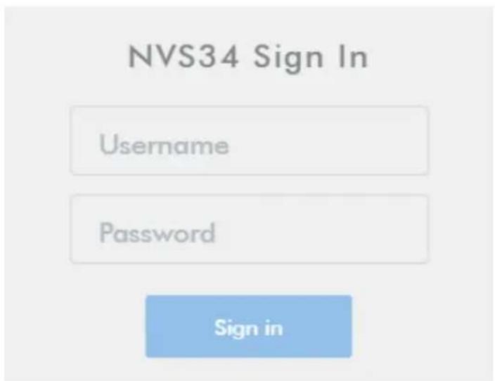
- Log in the NVS-34 web interface with the following credentials:
Username: admin
Password: 000000
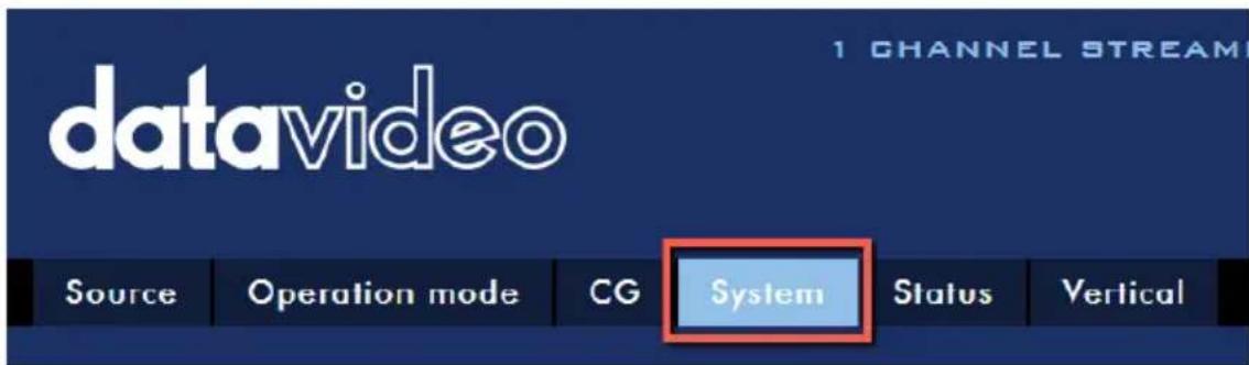
- Click the System tab to open the system configuration page.
- Scroll down to Firmware Update pane then click the Browse button to search for the latest firmware file on the PC's hard disk.
File Path
Browse
Update
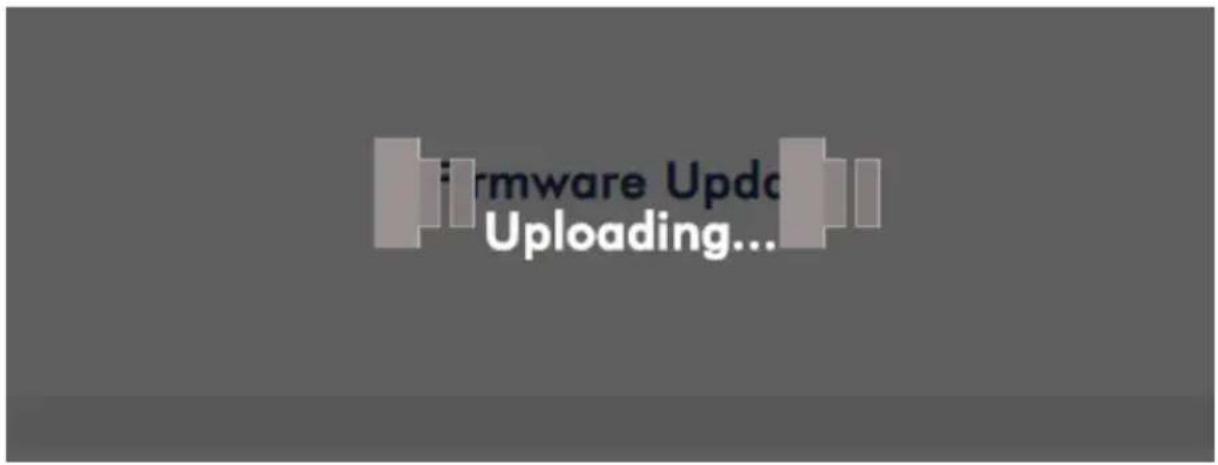
- After double clicking the firmware file, you will see the loading prompt as shown below, indicating that the file is being uploaded to the NVS-34.
- After the file has been successfully uploaded, you will see a file upload success message. Click the Update button to start the firmware update process.
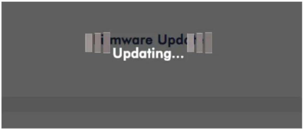
- The device will reboot itself after it is updated successfully.
Preparing for Rebooting!
57 Secs
Note: If the device is recording or streaming, you must turn them off before initiating the firmware update.
5 Recommended SD Cards
You should only use Class 10 SD card or above. In this appendix, you will find a list of SD cards recommended by Datavideo.
| Recommended SD Cards | |||
| No. | Brand | Model | Pictures |
| 1 | Kingston | SDHC I C10 16G | 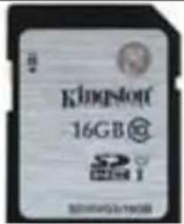 |
| 2 | SANDISK Extreme | SDXC I C10 U3 V30 64GB | 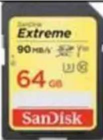 |
| 3 | SONY | SDXC I C10 U1 64GB | 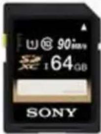 |
| 4 | SANDISK Extreme PRO | SDXC I C10 U3 128GB | 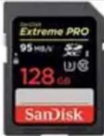 |
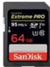 | |||
| 5 | SONY | SDXC I C10 U364GB | 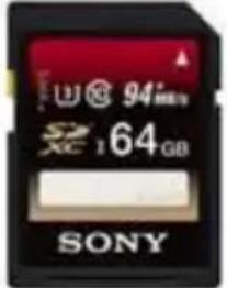 |
| 6 | TOSHIBA | SDHC C1016GB | 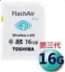 |
| 7 | SANDISK Extreme | SDHC C1016GB | 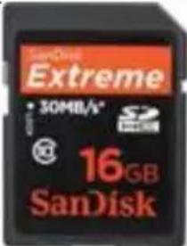 |
| 8 | ADATA Premier Pro | microSDXC I UHS-I U3 Class 10 with SD adapter64GB | 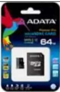 |
| 9 | SANDISK ULTRA® | SDHCTM/SDXCTM UHS-I128 GB | 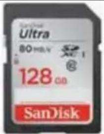 |
Compatible SD Card for Mobile Cast and NVS-33
- Kingston
SDHC C10
16GB

- SANDISK Extreme
SDXC C10 U3 V30
64GB

- SONY
SDXC C10 U1
64GB

- SANDISK Extreme PRO
SDXC C10 U3
128GB
- SONY
SDXC C10 U3
64GB

- TOSHIBA
SDHC C10
16GB

- SANDISK Extreme
SDHC C10
16GB

- ADATA Premier Pro
microSDXC UHS-I U3 Class 10
64GB
- SANDISK
ULTRA SDHC
SDXC UHS-I
128GB

6 Frequently-Asked Questions
This section describes problems that you may encounter while using the NVS-34. If you have any questions, please refer to related sections and follow all suggested solutions. If problem still exists, please contact your distributor or the service center.
| No. | Problems | Solutions |
| 1 | Unable to update firmware on MAC OS. | It is recommended to run NVS-34 web UI on Windows and the recommended browsers are Microsoft Edge, Google Chrome and Firefox. |
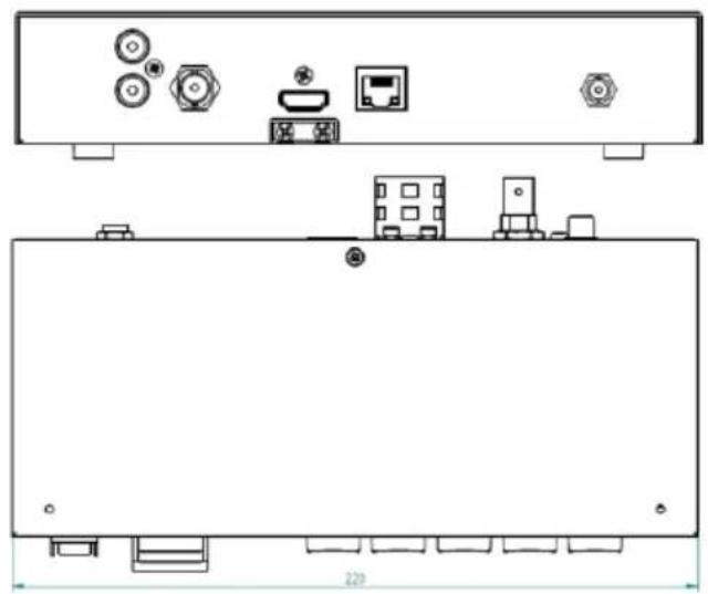
7 Dimensions
natural_image
Technical line drawing of a device rear panel with ports and connectors (no text or symbols)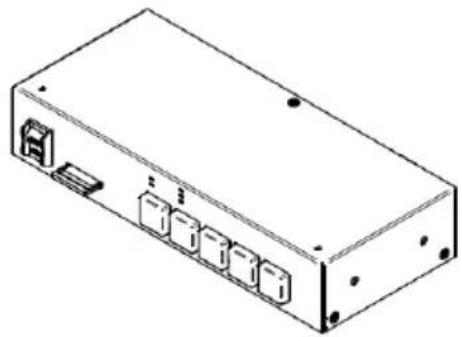
natural_image
Isometric line drawing of a rectangular electronic device with ports and connectors (no text or symbols)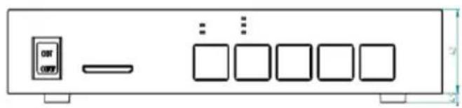
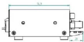
All measurements in millimeters (mm)
8 Specifications
| Interface | |
| Video Input | HDMI x 1SDI x 1 |
| Supported Input Video Resolution | 1080p60/59.94/501080p30/29.97/25/24/23.981080i60/59.94/50720p60/59.94/50480i59.94, 576i50 |
| Audio Input | SDI Embedded Audio x 1HDMI Embedded Audio x 11 RCA Unbalanced audio pair |
| Video Encoding | H.264/ AVC , Main / High Profile Level 4.1 |
| Video Bitrate | Record&Stream: 36Mbps(1080p50/60)Record Only: Up to 16Mbps(1080p50/60)Stream Only: Up to10Mbps(1080p50/60) |
| Video Rate Mode | CBR |
| Audio Mode | Stereo/Mono |
| Audio Bitrate | Stereo: 64 – 384 KbpsMono: 32 – 192 Kbps |
| Streaming Protocols | TS over TCP/UDP (unicast & multicast)RTSP over HTTP/TCP/UDP (RTSP Elementary Streaming)RTMP / RTMPS (Publish)HLS |
| Network Interface | RJ-45 x 1 (Ethernet 10/100 Mbps) |
| Recording File Format | MP4 |
| Storage Media | SD Card x 1 |
| Storage File System | FAT / NTFS / exFAT |
| Special Features | Vertical Video Streaming (Rotate and Crop) |
| Power Supply | DC 12V 11 W |
| Dimensions (LxWxH) | 220(W) x 95(D) x 47(H) mm |
| Weight | 0.7 kg |
| Operating Temperature | 0°C to 40°C (32°F to 122°F) |
Notes
Notes
Service & Support
It is our goal to make your products ownership a satisfying experience. Our supporting staff is available to assist you in setting up and operating your system. Please refer to our web site www.datavideo.com for answers to common questions, support requests or contact your local office below.

Please visit our website for latest manual update.
https://www.datavideo.com/product/NVS-34
datavideo
www.datavideo.com

@DatavideoUSA @DatavideoIndia2016
@DatavideoEMEA @Datavideojapan
@DatavideoTaiwan @DatavideoLatam
@DatavideoAsia @DatavideoBrasil

@Datavideo
@Datavideo_EMEA
@Datavideo Taiwan

@DatavideoUSA
@DVTWDVCN

@DatavideoUSA
@DatavideoEurope
All the trademarks are the properties of their respective owners.
Datavideo Technologies Co., Ltd. All rights reserved 2020
- Disclaimer of Product & Services
- FCC Compliance Statement
- Warnings and Precautions
- Warranty
- Standard Warranty
- Three Year Warranty
- Disposal
- For EU Customers only - WEEE Marking
- Introduction
- Features
- Major Five Features
- Supported Input Formats
- Operating System and Web Browser for the Web UI
- Streaming
- Recording
- System Diagram
- Connections and Control
- Front Panel
- Power Switch
- SD Card Slot
- INPUT Button
- BITRATE Button
- RECORD Button
- Start recording
- Stop recording
- STREAM Button
- Start streaming
- Stop streaming
- Vertical Button
- Rear Panel
- Audio Input
- RCA Unbalanced Audio Input
- Video Input
- HDMI Input
- SDI Input
- Network
- LAN
- Power
- DC IN 12V
- Video Streaming
- Streaming Network Connection and Device Search
- Connecting to a DHCP Network (DHCP Mode)
- Note: The NVS-34 will be automatically assigned an IP address upon connection to the DHCP network.
- Connecting to a NON-DHCP Network (Static IP)
- Device Reset
- Troubleshooting the Network Connection
- Advanced Troubleshooting
- Web User Interface
- Source
- Operation Mode
- Stream Mode
- Encoder Source
- Stream Type
- RTSP (Real Time Streaming Protocol)
- RTMP (Real-Time Messaging Protocol)
- TS (Transport Stream)
- Resolution
- Frame Rate
- Video Bitrate (bps)
- Profile
- Level
- Entropy
- GOP
- File Name
- Encoder Mode
- CG Layer
- CG Type
- Text
- Picture
- Location-X
- Location-Y
- Foreground Color
- 000000
- System
- Network Setting
- DHCP
- Static IP Address
- Subnet Mask
- Default Gateway
- Primary DNS (Optional)
- Secondary DNS (Optional)
- Account and Password
- Time Setting
- Type
- NTP Server
- Manual
- Time Zone
- Firmware Update
- Disk Format
- Device Name Setting
- Other Option
- Timeout Period
- System Control
- Restore to Default
- System Reboot
- Status
- Vertical
- Operations
- Video Streaming
- RTSP/TS/HLS
- Follow the steps below to obtain the RTSP URL:
- Play URL
- Follow the steps below to obtain the TS URL:
- Follow the steps below to obtain the HLS URL:
- RTMP
- RTMP URL
- Stream Name
- Account
- Password
- Text Overlay Video
- Stream and Record Buttons
- Restoring Factory Defaults
- Firmware Update
- Firmware Upgrade
- Preparing for Rebooting!
- Secs
- Recommended SD Cards
- Compatible SD Card for Mobile Cast and NVS-33
- Frequently-Asked Questions
- Dimensions
- Notes
- Service & Support
- datavideo
Brand : DataVideo
Model : NVS-34
Category : Media player