
DAC3 B - Headphones Benchmark - Free user manual and instructions
Find the device manual for free DAC3 B Benchmark in PDF.


| Product Type | Reference Stereo Digital-to-Analog Converter (PCM and DSD) |
| Model | Benchmark DAC3 B |
| D/A Conversion System | ESS ES9028PRO SABRE PRO 32-bit, 4:1 parallel conversion per channel |
| Supported Formats | PCM up to 24-bit/192 kHz; DSD (DoP 1.1) at 2.8224 MHz |
| Digital Inputs | 2 x Coaxial (RCA), 2 x Optical (TOSLINK), 1 x USB (Type B) – USB Audio 1.1 and 2.0 |
| Analog Outputs | 1 x Balanced XLR (male), 1 x Unbalanced RCA |
| Jitter Attenuation | Benchmark UltraLock3™ – jitter-immune to >12.75 UI |
| Headroom | 3.5 dB digital headroom above 0 dBFS; analog clip at +29 dBu |
| XLR Output Calibration | +24 dBu at 0 dBFS (0 dB pad); adjustable 0/10/20 dB passive pads |
| RCA Output Calibration | 2 Vrms at 0 dBFS |
| Dimensions (W x H x D) | 9.5" x 1.725" x 8.5" (249 x 44.5 x 216 mm) without connectors; overall depth 9.33" (237 mm) |
| Weight | 3 lb (1.36 kg) unit only; 4 lb (1.81 kg) with accessories |
| Power Requirements | 88–264 VAC, 47–63 Hz (universal power supply) |
| Power Consumption | < 0.5 W standby, 12 W typical, 15 W maximum |
| Fuses | Two 0.5 A 250 V Slo-Blo® 5x20 mm (Littelfuse HXP218.500 or equivalent) |
| Trigger | Bi-directional 12V trigger I/O (3.5 mm TRS jack), 200 mA current-limited output |
| Remote Control | Optional IR remote with metal housing (controls input selection, power, USB mode) |
| Display | Front-panel LEDs for input selection, sample rate, word length, and control lock |
| Special Functions | AUTO-ON, CONTROL-LOCK, Digital Pass-Through (D4 configurable as output), sample rate and word length display |
| Regulatory Compliance | FCC Class B, CE, RoHS |
| Warranty | 1 year standard, extendable to 5 years (US/Canada) or 2 years (international) with registration |
| Safety Notes | Always use grounded power cord; replace fuses with correct type; no user-serviceable parts inside; modifications void warranty |
| Maintenance | Keep dry and clean; avoid static discharge when changing internal jumpers; use a static wrist strap |
Frequently Asked Questions - DAC3 B Benchmark
User questions about DAC3 B Benchmark
0 question about this device. Answer the ones you know or ask your own.
Ask a new question about this device
Download the instructions for your Headphones in PDF format for free! Find your manual DAC3 B - Benchmark and take your electronic device back in hand. On this page are published all the documents necessary for the use of your device. DAC3 B by Benchmark.
USER MANUAL DAC3 B Benchmark
Benchmark DAC3 B Instruction Manual
Reference Stereo PCM and DSD D/A Converter with ESS9028PRO Conversion System
(Version 1.x Firmware)
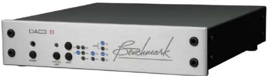
Safety Information
Fuses
CAUTION: FOR CONTINUED FIRE HAZARD PROTECTION ALWAYS REPLACE THE FUSES WITH THE CORRECT SIZE AND TYPE (0.5A 250 V SLO-BLO® 5 X 20 MM - LITTELFUSE® HXP218.500 OR EQUIVALENT). THE FUSE DRAWER INCLUDES TWO FUSES. ALWAYS REPLACE BOTH FUSES AT THE SAME TIME.
AC Input Voltage Range
NOTE: THE DAC3 IS EQUIPPED WITH A UNIVERSAL POWER SUPPLY. THERE IS NO VOLTAGE SELECTION SWITCH. AC VOLTAGE RANGE IS 88-264 VAC, 47-63 HZ. THE PRODUCT MAY ALSO BE OPERATED FROM DC POWER OVER A VOLTAGE RANGE OF 125-373 VDC.
Power Cord
CAUTION: ALWAYS USE A GROUNDED POWER CORD. THE PRODUCT IS EQUIPPED WITH A STANDARD IEC POWER ENTRY MODULE. USE AN IEC POWER CORD THAT IS EQUIPPED WITH THE APPROPRIATE CONNECTOR FOR YOUR LOCATION. CORDS ARE AVAILABLE FROM YOUR DEALER.
Modifications
CAUTION: DO NOT SUBSTITUTE PARTS OR MAKE ANY MODIFICATIONS WITHOUT THE WRITTEN APPROVAL OF BENCHMARK MEDIA SYSTEMS, INC. MODIFICATION MAY CREATE SAFETY HAZARDS AND VOID THE WARRANTY.
CAUTION: CHANGES OR MODIFICATIONS NOT EXPRESSLY APPROVED BY BENCHMARK MEDIA SYSTEMS COULD VOID THE USER'S AUTHORITY TO OPERATE THE EQUIPMENT UNDER FCC REGULATIONS.
Repairs
CAUTION: DO NOT SERVICE OR REPAIR THIS PRODUCT UNLESS PROPERLY QUALIFIED. ONLY A QUALIFIED TECHNICIAN SHOULD PERFORM REPAIRS.
Contents
Safety Information 2
Fuses 2
AC Input Voltage Range 2
Power Cord 2
Modifications 2
Repairs 2
Features 4
Introduction 5
Applications 5
DAC3 vs. DAC2 5
DAC3 vs. DAC1 5
DAC3 Technologies 5
Front Panel 8
Rear Panel 8
Quick Start Guide 9
Audio Inputs 9
Remote Control (optional) 9
Front Panel Controls 10
Front Panel Display 11
Operational Details
AUTO-ON Function 13
CONTROL-LOCK Function 13
Bi-directional 12V Trigger 14
HPA4, LA4 Compatibility 16
USB MODE Selection 16
High-Current Outputs 16
Driving Power Amplifiers 16
Digital Pass-Through 17
Firmware Version Identification 18
Rear Panel
Inputs 19
Outputs 22
AC Power-Entry and Fuse Module 23
Internal Settings
Jumper-Configured Options 24
Removing Top Cover 24
XLR Output Pads 25
Digital PASS-THROUGH Function 26
Rack Mounting 27
Benchmark Rack Mount Tray 27
Benchmark 1/2-Wide Blank Plate 27
DAC1, DAC2 and DAC3 Family History 28
DAC1 Series 28
DAC2 Series 28
DAC3 Series 29
Benchmark Technologies 30
Native DSD Conversion 30
High Headroom DSP 30
32-bit SABRE-PRO D/A System 31
Diagnostic Displays 31
Bi-Directional 12 Volt Trigger 31
Distributed Power Regulation 32
Differential Amplifiers 32
Jitter-Immune UltraLock3 ^TM 32
Multi-Mode Asynchronous USB Audio 35
USB Driver Installation 37
Performance Graphs 42
Specifications 57
Audio Performance 57
Group Delay (Latency) 58
Digital Audio Inputs 58
Jitter Tolerance 58
Balanced Analog Outputs 59
Unbalanced Analog Outputs 59
Status Display 59
AC Power Requirements 60
Dimensions 60
Weight 60
Regulatory Compliance 61
FCC and RoHS Compliance Statements 61
FCC Notice (U.S. Only) 61
RoHS Compliant Information 61
CE Certificate of Conformity 62
Warranty Information 63
Benchmark 1-Year Warranty 63
Benchmark Extended Warranty Options 64
Notes on Warranty Repairs 64
Features
- Fixed Gain Calibrated Outputs – XLR outputs are calibrated to +24 dBu at 0 dBFS (pads at 0 dB), RCA outputs are calibrated to 2 Vrms at 0 dBFS (calibration is equivalent to "HT MODE" or "CALIBRATED MODE" on other DAC3 models)
• CONTROL LOCK - Disables keypad and remote control to prevent accidental changes - Low-Impedance Passive Output Pads – 0, 10, and 20 dB – optimize output level to power amplifiers and other downstream devices to maximize system SNR (Page 25)
• SABRE PRO - 32-bit PCM D/A conversion system, four 32-bit D/A converters per channel
• SABRE PRO – Native DSD D/A conversion system, four 1-bit DSD D/A converters per channel - Benchmark UltraLock3™ Jitter Attenuation System – eliminates jitter-induced distortion
- High Headroom DSP - provides 3.5 dB of analog and digital headroom above 0 dBFS to completely eliminate the clipping of intersample peaks
• Multi-Mode Asynchronous USB Audio 2.0 - 24 bit/192 kHz, DSD (DoP 1.1) - Driverless Asynchronous USB Audio 1.1 - 24-bit/96 kHz
- Sample Rate Display – displays the measured sample rate, and format (PCM or DSD)
- Word Length Display – displays the measured word length
• 2 Coaxial Digital Inputs - 24-bit/192 kHz PCM, DSD (DoP 1.1)
• 2 Optical Digital Inputs - 24-bit/96 kHz PCM - 1 Coaxial Digital Output – digital pass through from USB, Coax, and optical inputs when function is enabled (Page 26)
• 2 Stereo Analog Outputs – 1 pair balanced (XLR), plus 1 pair unbalanced (RCA)
• IR Remote with metal housing provides control of all functions (optional) - Automatic De-Emphasis – automatically responds to consumer pre-emphasis bit (44.1, 48 kHz)
- 12V Trigger I/O – bi-directional 12V trigger can act as input, output, or both (Page 14)
• AUTO-ON Function - can be programmed to turn on when AC is applied (Page 13)
• Power Switch – very low standby power, <0.5 W at 120 VAC
• High-Efficiency Low-Noise Power Supplies – only 12-15 W, 88-264 VAC, 47-63 Hz - Meets FCC Class B and CE emissions requirements
- Tested for immunity to radiated and conducted RF interference
Introduction
Applications
The DAC3 B is the ideal converter to use in front of Benchmark's HPA4 headphone amplifier or LA4 line amplifier. It is also ideal for many professional studio applications. It delivers the full performance of the flagship DAC3 HGC, but eliminates the volume control, the analog inputs, the mute and polarity controls, and the headphone amplifier.
The DAC3 B is a professional reference-grade audio digital to analog converter with a fixed-gain output. The DAC3 B supports 24-bit D/A conversion of PCM at sample rates up to 192 kHz. It also supports direct conversion of 1-bit DSD at a 2.8224 MHz sample rate. It is designed to be very transparent and this makes it well-suited for critical monitoring in studio control rooms and mastering rooms.
The DAC3 B provides D/A conversion and digital source selection. The DAC3 B is ideal for use with the Benchmark HPA4 headphone/line amplifier or the LA4 line amplifier. These devices provide a very high-performance analog volume control that is a perfect complement to the fixed-gain output of the DAC3 B.
The fixed-gain DAC3 B has many applications in a professional environment where a calibrated output is required. The CONTROL LOCK function can be enabled to prevent accidental changes to the settings.
DAC3 vs. DAC2
The DAC3 builds upon Benchmark's highly successful DAC2 product family. The DAC3 maintains the familiar DAC2 form factor, but adds the higher performance available from the new ES9028PRO D/A converter. The DAC3 offers the following improvements over the DAC2:
• Active 2nd Harmonic Compensation
• Active 3rd Harmonic Compensation
- Lower THD
- Lower passband ripple
- Improved frequency response
- Increased Dynamic Range
- Faster PLL lock times
- Faster switching between inputs
DAC3 vs. DAC1
The DAC3 and DAC2 add these features that are not found on the DAC1:
• Asynchronous 192kHz USB Audio 2.0
• 32-bit D/A conversion system
• Word Length Display
• Sample Rate Display
- Polarity Control
- Direct DSD D/A Conversion
-20 dB DIM
• Bi-Directional 12V Trigger
• Power Switch with Auto-On Function
• Digital Pass-Through
• High-Headroom DSP
• Additional I/O
DAC3 Technologies
4:1 Parallel Conversion Structure
The conversion system in the DAC3 achieves a 6 dB signal to noise improvement through the use of 4:1 summing. The ES9028PRO D/A is an 8-channel 32-bit converter. In the DAC3, four channels are summed in the analog domain to form each of the two output channels.
The 4:1 summing also improves the THD. The non-linearities in individual conversion channels are averaged across the four summed channels and incoherent nonlinearities are attenuated by 6 dB.
Harmonic Compensation
The ES9028PRO has two distortion compensation systems that independently remove most of the 2nd and 3rd harmonic distortion in the D/A converter. Benchmark's ultra-clean analog output stages allow these systems to be fully leveraged in the DAC3.
High-Headroom Digital and Analog Processing
The DAC3 B has generous amounts of analog and digital headroom. The analog clip point is above 29 dBu. The digital clip point is +3.5 dBFS and is aligned to 27.5 dBu. The factory calibration is +24 dBu at 0 dBFS. This means that the DAC3 B has 3.5 dB of digital headroom above 0 dBFS, and another 1.5 dB before reaching analog clip. The digital headroom prevents the clipping of intersample overs. The analog headroom allows accurate reproduction of intersample peaks without clipping.
No Clipping of Intersample Overs
The DAC3 is one of very few D/A converters that can accurately reproduce intersample overs without clipping. Intersample peaks can reach +3.01 dBFS and commonly occur many times per second in most 44.1 kHz and 48 kHz recordings. When recordings are ripped using lossy compression systems (such as MP3), additional intersample overs are often created. Most converters (including the DAC1) produce bursts of distortion at every occurrence of an intersample over. In contrast, the DAC2 and DAC3 converters cleanly reproduce all intersample overs without clipping.
Low-Noise Power Supplies
The DAC3 uses high-efficiency low-noise power supplies. Each critical subsystem also has at least one dedicated low-noise regulator. The high-efficiency supplies deliver the substantial power required by the low-impedance circuits and the output line drivers. A power switch is included. The standby power consumption is less than 0.5 W when the unit is off.
Low Magnetic Emissions
The magnetic components in the DAC3 power supplies operate at over 800 kHz. This allows the use of very small magnetic components that emit correspondingly small magnetic fields. This virtually eliminates all traces of line-frequency components in the output spectrum of the DAC3. This also means that the DAC3 can be placed in close proximity to any audio component without causing interference with the other component.
UltraLock3™ Clock System
UltraLock3 ^™ provides the outstanding jitter attenuation of Benchmark's UltraLock2 ^™ system while providing virtually instantaneous (6 ms) lock times.
Dual-Mode USB Input
The DAC3 has a USB input that can be operated in two modes; driverless USB
Audio 1.1, and a high sample rate USB
Audio 2.0. Both use asynchronous clocking to eliminate the USB interface as a source of clock jitter.
Note: To provide full backward and forward compatibility, the DAC3 uses the DAC2 USB drivers. This prevents the need to install two different sets of drivers. Please note that the DAC3 USB input will be identified as "Benchmark DAC2" in your computer control panels. This is intentional.
Asynchronous USB Audio 2.0
The USB Audio 2.0 interface supports DSD and 192 kHz, 24-bit PCM. No drivers are required for Apple or Linux operating systems. Drivers are provided for Windows operating systems at:
BenchmarkMedia.com/drivers
Native Asynchronous USB 1.1
The DAC3 has a driverless USB Audio 1.1 mode that supports 96 kHz, 24-bit PCM with all operating systems. This mode provides a quick and easy connection to a wide variety of computers and tablets without installing a driver.
Low-Impedance Passive Attenuators
Like the DAC1 and DAC2, the DAC3 includes low-impedance passive attenuators on the XLR outputs. These attenuators can be adjusted to optimize the interface with preamplifiers, power amplifiers or powered monitors. This optimization places the system volume control in its best operating range. This exclusive Benchmark feature can provide substantial improvements in the performance of the playback signal chain.
Native DSD Conversion
The DAC3 supports native DSD conversion. This feature was not available on the DAC1. DSD signals can be delivered to the USB or Coaxial inputs in DoP 1.1 format. The DSD signal is then routed directly to a bank of 1-bit DSD D/A converters. Four balanced 1-bit converters are summed together for each balanced output.
Digital Pass-Through
The second coaxial input (D4) can be reconfigured as a digital output. When operating as an output, any selected digital input is passed through to D4 without any processing. Optical, coaxial, and USB inputs can be passed through to the D4 connector. This even includes special signals such as DoP, DTS, Dolby Digital, even when these signals cannot be decoded by the DAC3.
Bi-directional 12V Trigger
The 12 Volt trigger can be connected to other audio components so that an entire audio system can turn on and off in a sequenced fashion. The DAC3 trigger I/O can be connected to a preamplifier, power amplifier, or both. The DAC3 will pull the trigger I/O to 12 volts DC while the DAC3 is on. If the DAC3 is off and an external device pulls the trigger I/O to 12 volts, the DAC3 will turn on.
Auto-On Function
The DAC3 can be programmed to automatically turn on when AC power is applied. (Page 13)
Front Panel
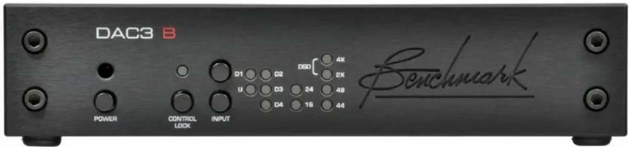
- IR Sensor
- Power Button
• Control-Lock Button and Indicator - Input Select Buttons
- Input Indicators
• Word-Length Indicators
• Sample-Rate Indicators
Rear Panel
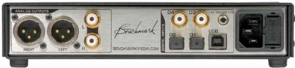
• Balanced Outputs
• Unbalanced Outputs
- Digital Inputs
- 12V Trigger I/O
• IEC Power Entry with Fuses
Quick Start Guide
Audio Inputs
The DAC3 B features five stereo digital inputs (2 coaxial, 2 optical, and 1 USB). The coaxial and optical inputs accept professional (AES) and consumer (S/PDIF) data formats at word lengths up to 24-bits.
Tip: We recommend using the coaxial or USB inputs for sample rates above 96 kHz. Optical interfaces are not always reliable at sample rates above 96 kHz.
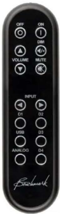
Remote Control (optional)
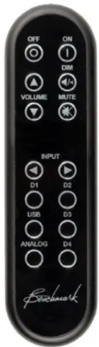
Tip: The remote control is designed to have a long operating range. In most applications it is not even necessary to point the remote directly at the DAC3. The IR sensor is located above the POWER button.
The chart at the right summarizes the functions of the optional IR remote control.
| OFF | Turns the unit off. Any devicesslaved to the 12V TRIGGER willalso turn off in a controlledsequence.Press and hold the OFF button for3 seconds to force the 12VTRIGGER off (only necessarywhen another device is acting as aTRIGGER BUS MASTER). |
| ON | Turns the unit on. Any devicesslaved to the 12V TRIGGER willalso turn on in a controlledsequence. |
| VOLUME | Not used. |
| DIM | Not used. |
| MUTE | Not used. |
| INPUT | Not used. |
| D1 | Selects optical digital input D1. |
| D2 | Selects optical digital input D2. |
| D3 | Selects coaxial digital input D3. |
| D4 | Selects coaxial digital input D4. |
| USB | Selects USB input.Press and hold the USB button for3 seconds to toggle between theUSB 1.1and USB 2.0modes. |
| Analog | Not used. |
Tip: To provide system compatibility with the Benchmark HPA4 and LA4, the DIM, MUTE, VOLUME UP/DOWN, INPUT UP/DOWN and ANALOG keys are not used by the DAC3 B.
Tip: The CONTROL-LOCK button disables the remote control and all other buttons on the front panel.
Front Panel Controls
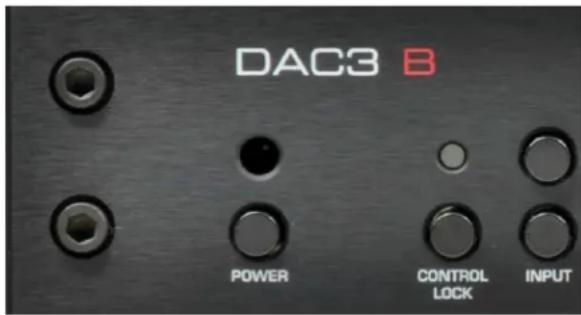
Tip: The CONTROL-LOCK button disables the remote control and all buttons on the front panel. Use this function in dedicated applications to prevent loss of audio. If you are not using the 12V TRIGGER I/O, you will also want to activate the AUTO-ON feature because the POWER button is disabled.
Tip: When AUTO-ON is enabled, a switched AC outlet can be used to turn your system on and off. The 12V TRIGGER I/O can be used as a trigger output to control the power state of additional components.
Tip: The IR remote control sensor is located directly above the POWER button.
The chart at the right summarizes the functions of the front-panel controls.
| POWER | Turns the unit on or off. Any devices slaved to the 12V TRIGGER will also turn on or off in a controlled sequence.Starting with the unit off, press and hold the POWER button for 3 seconds to set the AUTO-ON function.Starting with the unit on, press and hold the POWER button for 3 seconds to clear the AUTO-ON function.If AUTO-ON is set, the POWER button is disabled.If CONTROL-LOCK is on, press the POWER button for 3 seconds to turn the unit off. |
| CONTROL LOCK | Press and hold for 3 seconds to toggle CONTROL-LOCK on or off.When the CONTROL-LOCK light is on, the front panel keys and remote control are disabled. |
| INPUT | Press to select inputs.If CONTROL-LOCK is on, the INPUT buttons are disabled.Press and hold both input buttons for 3 seconds to toggle between USB 1.1 and USB 2.0. |
Front Panel Display
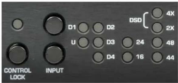
There are twelve status indicator lights on the front panel. At least one light will be illuminated whenever power is on.
Input Indicators
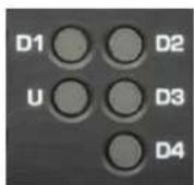
The input indicators show which input is selected.
A flashing light indicates an error on a digital input.
| U | A solid blue light indicates that the USB input is selected and operating normally. A blinking blue light indicates that the input is selected but a connection to a computer has not been established. |
| D1 | A solid blue light indicates that optical input D1 is selected and operating normally. A blinking blue light indicates that the input is selected but audio data is not being received. |
| D2 | A solid blue light indicates that optical input D2 is selected and operating normally. A blinking blue light indicates that the input is selected but audio data is not being received. |
| D3 | A solid blue light indicates that coaxial input D3 is selected and operating normally. A blinking blue light indicates that the input is selected but audio data is not being received. |
| D4 | A solid blue light indicates that coaxial input D4 is selected and operating normally. A blinking blue light indicates that the input is selected but audio data is not being received. |
Note: D4 cannot be selected if the Digital
Pass Through function is enabled.
Instructions for configuring this jumper-selected function can be found in the Internal Settings section of this manual (Page 26).
Input Error Codes
The input indicators flash when errors are present on the selected digital input. There are no error indications for analog inputs. Use the following table to diagnose the problem:
| Slow Flash (2Hz) | No digital signal (output muted) |
| Med. Flash (7Hz) | Data transmission errors or Non-PCM (output muted) |
| Rapid flashes (14Hz) | Non-audio data is being received (output muted) |
| Intermittent flashes | Some data corruption is occurring, converter may be interpolating to replace invalid samples, check the cable. |
Tip: Common causes of input errors:
• Disconnected or faulty cable
- Use of excessively long digital cables
- Use of analog cables for digital signals
- Use of optical cables for sample rates exceeding 96 kHz
- Incompatible data type (AC3, ADAT, etc.)
• Non-audio data is being received
Digital Format Indicators
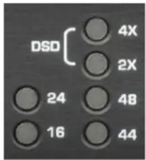
Two lights indicate the measured word length of the selected digital input.
Four lights indicate the sample rate and format of the selected digital input.
Tip: Computers, disk players, and streaming devices often subject the digital signal to sample rate conversion, changes in word length, PCM to DSD conversions, and other forms of digital processing that may degrade the quality of the audio. This display makes it easy to detect these processes.
Word Length Indicators
The 16 and 24 lights indicate the measured word length of the selected digital input. The DAC3 detects active data bits and displays the results as follows:
| 16 Only | Measured input word length is 16 bits. |
| 16 and 24 | Measured input word length is 17 to 23 bits. |
| 24 Only | Measured input word length is 24 bits. |
| Both Off | Measured input word length is less than 16 bits. |
Format indicators
The 44, 48, 2X, 4X, and DSD lights indicate the sample rate and format of the selected digital input as follows:
| 44 Only | The input format is PCM at a sample rate of 44.1 kHz (CD sample rate). |
| 48 Only | The input format is PCM at a sample rate of 48 kHz (often used with video). |
| 44 and 2X | The input format is PCM at a sample rate of 88.2 kHz (high-resolution audio format). |
| 48 and 2X | The input format is PCM at a sample rate of 96 kHz (high-resolution audio format). |
| 44 and 4X | The input format is PCM at a sample rate of 176.4 kHz (high-resolution audio format). |
| 48 and 4X | The input format is PCM at a sample rate of 192 kHz (high-resolution audio format). |
| DSD(4x and 2X) | The input format is 1-bit DSD at a sample rate of 2.8224 MHz (high-resolution audio format). Note: DSD must be streamed in DoP format. |
| All Off | Digital signal is not present or is not in a supported format. |
Operational Details
AUTO-ON Function
The DAC3 can be programmed to automatically turn on whenever AC power is applied. This function allows automation using switched AC outlets. When AUTO-ON is enabled, the DAC3 cannot be turned off without removing AC power.
The AUTO-ON function is programmed by pressing and holding the POWER button on the front panel for three seconds. This function cannot be programmed from the remote control. This limitation prevents accidental access to this special feature.
Tip: The AUTO-ON function cannot be changed if the CONTROL-LOCK is on. Turn the CONTROL-LOCK off before attempting to change the AUTO-ON function.
Enabling AUTO-ON
Starting with the DAC3 off, press and hold the POWER button for 3 seconds.
If AUTO-ON has been successfully enabled, the unit cannot be turned off using the POWER button or the OFF button on the remote.
Disabling AUTO-ON
Starting with the DAC3 on, press and hold the POWER button for 3 seconds. At the end of 3 seconds the DAC3 will power down if the AUTO-ON mode has been successfully disabled.
CONTROL-LOCK Function
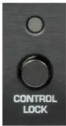
The CONTROL-LOCK function disables the remote control and all buttons on the front panel.
Use the CONTROL-LOCK function when the DAC3 will be used in a dedicated application using just one digital input. This feature prevents accidental loss
of audio in these dedicated applications.
Controls are locked when the CONTROL-LOCK light is on.
Press the CONTROL-LOCK button for 3 seconds to toggle this function on or off.
Tip: If CONTROL-LOCK is on, but AUTO-ON is off, the unit can be powered down by pressing and holding the POWER button for 3 seconds. This turns the unit off, but does not turn off the CONTROL-LOCK function.
Bi-directional 12V Trigger
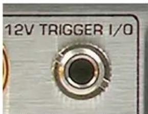
Benchmark has reinvented the 12 volt trigger by adding bi-directional signaling. The trigger connection on the DAC3 can be used as
an input, an output, or both. It is compatible with any common 12 volt trigger input or output. The 12V TRIGGER I/O can be used to turn other audio components on when the DAC3 turns on. The DAC3 can also turn on and off in response to other connected components. The Benchmark bi-directional 12V Trigger is compatible with virtually all trigger systems.
The 12V TRIGGER I/O can be connected to the trigger input or output ports on a preamplifier, power amplifier, or both.
The DAC3 can send a 12 Volt DC trigger signal to start other components in the system, or it can wake up in response to an externally generated trigger signal. The DAC3 automatically configures its trigger I/O port as an input (slave) or output (master).
Trigger Output (DAC3 is Master)
When the DAC3 is turned on using the POWER button (on the front panel), or the ON button (on the remote), the DAC3 configures itself as a trigger master and will drive the 12V TRIGGER I/O to 12 volts DC and hold it there while the DAC3 is on. The trigger output signal generated by the DAC3 is delayed so that the DAC3 can stabilize before downstream devices (such as power amplifiers) turn on. When powering down, the DAC3 will mute before allowing the trigger line to drop low. The DAC3 keeps the internal power supplies running for 10 seconds after dropping the trigger. This delay gives other triggered components ample time to mute and shut down.
If the AUTO-ON function is enabled, the DAC3 will automatically turn on when AC power is applied, configure itself as a trigger master, and ignore any external signaling on the 12V TRIGGER I/O line. In AUTO-ON mode, the DAC3 will always drive the 12V TRIGGER I/O line to 12 V (after a short start-up delay).
Trigger Input - (DAC3 is Slave)
If the DAC3 is off and an external device pulls the trigger I/O to 12 volts, the DAC3 will configure itself as a trigger slave and will follow the actions of the trigger input. The DAC3 will then turn off when the external device stops sending the 12 V trigger.
Typical Trigger Applications
In most systems, the 12V TRIGGER will be used to connect the DAC3 to one other device. The DAC3 can be connected to the first trigger input at the beginning of a trigger chain, or it can be connected to the last trigger output at the end of the chain (less common).
Typical trigger applications:
- DAC3 B → Preamplifier → Amplifier
- DAC3 B → LA4 → AHB2
• DAC3 B → Headphone Amplifier • DAC3 B → HPA4 - DAC3 B → Amplifier
- DAC3 B → AHB2
The Benchmark bi-directional trigger system also supports multiple trigger ports wired together on a bus.
A group of Benchmark trigger ports can be connected to a group of non-Benchmark trigger input ports to form a single trigger bus. A bus should never be connected to more than one non-Benchmark trigger output port. If an output port is connected to the bus, this device should be used to start the audio system.
A 3.5 mm (1/8") TRS "Y" cable can be used to split the trigger output of the DAC3 to feed more than one trigger input.
Benchmark AHB2 power amplifiers have two trigger I/O ports that are wired in parallel. This makes it easy to connect more than one power amplifier to a trigger bus (without the use of a "Y" cord). Connect a trigger cable between the DAC3 and the first amplifier. Use another trigger cable to connect this amplifier to the next amplifier. Any number of Benchmark amplifiers can be added to the trigger bus. The DAC3 will turn on first, and after a delay, all of the amplifiers will turn on together.
Bi-Directional Trigger Applications
Benchmark products support bi-directional communications over a trigger bus. Any Benchmark product connected to the bus can turn the entire system on or off. Because of the bi-directional design, any power button on a Benchmark DAC3 or AHB2 can be used to start or stop the system.
The Benchmark device that starts the system will become the trigger master. If the trigger master is turned off, all slave devices will follow. If a slave device is turned off, all other devices will stay on.
If the DAC3 is used to turn the system on, any connected AHB2 amplifiers will become slave devices and they can be turned off without shutting down the DAC3.
Slave devices can force the entire trigger bus to shut down if the POWER button or OFF button is pressed and held for 3 seconds.
Tip: Press and hold the POWER button on any Benchmark device for 3 seconds to force a shutdown of the entire trigger-connected system.
Trigger Specifications
The Benchmark 12V TRIGGER I/O has a wide operating range to allow interfacing with most other DC trigger systems. It should only be used with trigger inputs that are designed to tolerate 12 VDC.
• 12 VDC 200 mA current-limited output
- Input responds to 3.3 V logic and higher
• Maximum input voltage = 30 VDC
• Maximum reverse input voltage = -0.3 VDC
- Input Impedance = 20 k Ohms
• 1/8" (3.5 mm) TRS jack
- Tip = 12 Volt Trigger I/O
• Ring = no connection
- Sleeve = chassis ground
HPA4, LA4 Compatibility
The DAC3 B is designed to work seamlessly with Benchmark line amplifiers (such as the HPA4 and LA4).
The line amplifier will control the system volume and analog input switching. The DAC3 B will be used to select the digital inputs. Both are controlled from a single Benchmark remote control.
USB MODE Selection
The DAC3 supports two USB MODES:
- USB Audio 1.1 mode - up to 24 bits at 96 kHz
- USB Audio 2.0 mode - up to 24 bits at 192 kHz plus DSD in DoP 1.1 format
Caution: Close all USB audio playback applications before changing the USB MODE. If an audio application is playing while the USB MODE is changed, the audio application may freeze. Avoid any unnecessary switching between USB MODES. Rapid switching between modes can confuse some operating systems.
Note: The computer and DAC3 must be connected and both must be on before the USB MODE can be changed.
To change the USB MODE, press and hold the USB button on the remote control for 3 seconds. If a remote control is not available, simultaneously press and hold both INPUT buttons on the front panel for 3 seconds.
Tip: The 4X or 2X lamp will flash once every time the USB input is selected. This flash provides a convenient indication of the current USB MODE. A flash of the 4X lamp indicates that the unit is in USB Audio 2.0 mode. A flash of the 2X lamp indicates that the unit is in USB Audio 1.1 mode.
High-Current Outputs
The RCA and XLR outputs on the DAC3 B are equipped with low-impedance high-current drivers. These robust outputs are well equipped to drive a wide variety of input impedances. The DAC3 B outputs remain clean when driving inputs that present difficult loads (high input capacitance and/or low input impedance).
The XLR outputs on the DAC3 B are equipped with jumper-configured passive low-impedance output pads. These pads can be set to an attenuation of 0 dB (pad off), 10 dB, or 20 dB. The pads should be used to match the output level of the DAC3 B to the input sensitivity of the downstream device.
Tip: In most applications we recommend placing a Benchmark HPA4 or LA4 line amplifier between the DAC3 B and the power amplifier. These Benchmark line amplifiers will optimize the analog interface between the DAC3 and the power amplifier while providing a stepped relay gain control with exceedingly low THD and noise. The HPA4 or LA4 provide a transparent path between the DAC3 B and a power amplifier.
Driving Power Amplifiers
If the system volume is being controlled digitally by an upstream device, the DAC3 B can be connected directly to an audio power amplifier or a set of powered monitors. This direct connection provides a clean path between the DAC3 B and the amplifier, but it is important to match the signal levels between the DAC3 B and the power amplifier in order to prevent excessive use of the upstream digital volume control.
The XLR outputs are equipped with adjustable pads that can be used to optimize the system gain structure in order to maximize the system noise performance.
Most power amplifiers and powered monitors will require the use of the 10 dB or 20 dB
pads. Use the 0 dB setting when driving a Benchmark AHB2 power amplifier.
Tip: The Benchmark AHB2 power amplifier has a unique low-gain topology that allows it to accept full studio-level input signals. This high-level interconnection provides a very low-noise connection between the DAC3 and the AHB2. Set the input SENSITIVITY switch on the AHB2 to 22 dBu (all the way down). This places the AHB2 full-power output point at an input level of 22 dBu. This level is exactly 2 dB lower than the calibrated output level of the DAC3 B (when the pads are set to 0 dB). This configuration optimizes the gain-staging between the DAC3 and the AHB2.
Tip: If you are using a direct connection between a DAC3 B and a non-Benchmark power amplifier, the XLR pads should be set so that a normal listening level is reached when the system volume control is near its maximum setting. This will optimize the gain-staging between the DAC3 B and your power amplifier.
Tip: Increase the pad setting if a comfortable listening level is reached while the system volume control is well below maximum.
Tip: Decrease the pad setting if a comfortable listening level cannot be reached when the system volume control is at maximum.
Instructions for setting the XLR pad jumpers are detailed in the Internal Settings section of this manual. The DAC3 B is shipped with the XLR pads disabled (set to 0 dB). No adjustments will be necessary if you will be using a Benchmark AHB2 power amplifier or Benchmark line amplifier.
Digital Pass-Through
The second coaxial input (D4) can be reconfigured as a digital output. When operating as an output, any selected digital input is passed through to D4 without any processing.
Optical, coaxial, and USB inputs (U, D1, D2 and D3) can be passed through to the D4 connector. The signals are buffered but are not processed in any way. For this reason, any data format can be passed through to the D4 connector, even when these formats cannot be decoded by the DAC3. Surround formats, such as DTS, Dolby Digital, cannot be decoded by the DAC3, but they can be passed to a surround system using the digital pass-through function.
The digital pass-through can also be used to provide the following digital signal conversions:
- Optical to Coaxial
- USB to Coaxial
• Coaxial to Coaxial (buffering)
DoP encapsulated DSD can also be passed through D4. DSD files on a computer can be sent in DoP to the USB input on the DAC3. The USB input can be routed to coaxial output D4. This output can be recorded by any 24-bit, 176.4 kHz digital recorder with a coaxial input. The PCM digital recorder can then be used to play the DSD recordings.
Firmware Version Identification
The firmware version is displayed during the lamp test while the DAC3 B is turning on. At least one lamp in the INPUT INDICATOR will flash rapidly while the remaining lamps will be on. The flashing lamps identify the firmware version. The values of each lamp are shown in this chart. Add the values of all flashing lamps to determine the version number. If no lamp flashes in the second column, the second digit is a 0.
| Digit 1 | Digit 2 | |||
| 2 | D1 | D2 | .4 | |
| 1 | U | D3 | .2 | |
| D4 | .1 | |||
Example 1: The U lamp is the only lamp that flashes. The firmware version is 1.0.
Example 2: The U and D4 lamps flash. The firmware version is 1.1.
Example 3: The D1 lamp is the only lamp that flashes. The firmware version is 2.0.
Rear Panel
Inputs
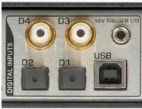
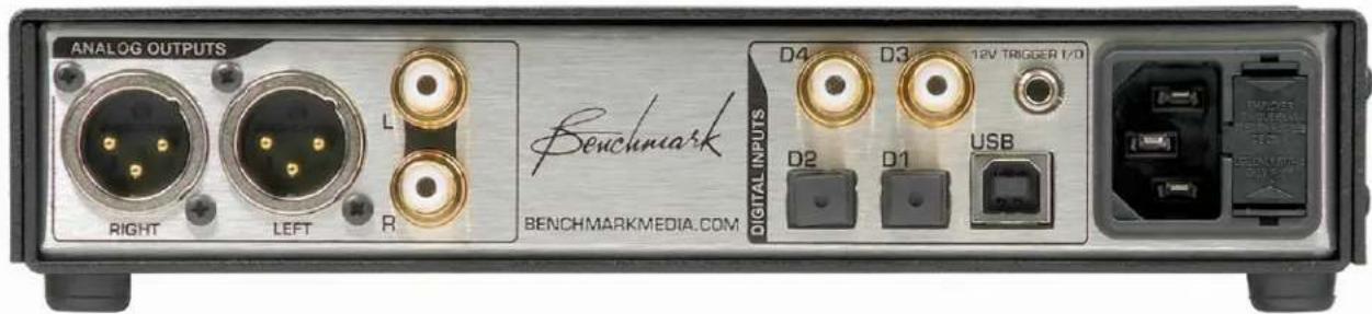
There are five stereo digital inputs on the DAC3 B:
• USB - USB Audio 1.1 or 2.0 Input
• D1 - Optical Digital Input
• D2 - Optical Digital Input
• D3 - Coaxial Digital Input
• D4 - Coaxial Digital Input or Output*
These inputs are selected using the INPUT buttons on the front-panel or on the remote-control.
* D4 can be jumper-configured as a digital PASS-THROUGH output. When enabled, the selected digital input will be routed to the internal D/A converter and to output D4. The selected input will be buffered and sent to output D4 even if the format cannot be decoded by the DAC3 B.
The digital inputs support PCM stereo AES/EBU and SPDIF digital formats. Maximum word length is 24-bits. Maximum sample rate is 192kHz.
The digital inputs also support DSD stereo at a sample rate of 2.8224 MHz using DoP 1.1 encapsulation.
The USB input has two operating modes:
• USB Audio 1.1 - PCM up to 24-bits at 96 kHz
- USB Audio 2.0 - PCM up to 24-bits at 192 kHz and DSD (DoP 1.1 format)
Caution: The optical inputs (D1 and D2) are not recommended for DSD or for sample rates above 96 kHz. Optical connections may be unreliable at sample rates above 96 kHz.
Tip: The DAC3 B will not decode multichannel digital formats such as AC3, and Dolby Digital. The audio will mute and the INPUT INDICATORS will flash whenever an incompatible format is connected to the selected digital input. If the PASS-THROUGH mode is enabled, these multichannel formats can be sent to a surround processor using connector D4 as a digital output.
Caution: The 12V TRIGGER I/O is not an audio connection! This is a 12V DC connection for synchronizing the on and off sequencing of an entire audio system.
Digital Inputs - Overview
All of the digital inputs on the DAC3 B use Benchmark's UltraLock3™ system to remove virtually all of the interface jitter. The result is that all digital inputs deliver identical audio performance. The USB, optical, and coaxial digital inputs will all sound identical if they receive identical data.
Computer Input - USB
The USB input accepts a Type-B male USB connector. A Type-A to Type-B USB cable is provided with the DAC3 B. The USB cable connects the DAC3 B directly to a computer's USB output.
The USB input supports 44.1, 48, 88.2, 96, 176.4, and 192 kHz PCM sample rates at word lengths up to 24-bits. The USB input also accepts DSD in DoP 1.1 format.
The DAC3 B can be configured as a USB Audio 1.1 or USB Audio 2.0 device. Press and hold the USB button on the REMOTE for three seconds to toggle the USB MODE. If a remote is not available, simultaneously press and hold both input buttons on the front panel for three seconds.
The USB AUDIO 1.1 mode does not require the installation of a driver. It allows a quick driverless connection to windows machines when playing sample rates of 96 kHz or less. In this mode, Windows machines can begin streaming audio within seconds after the DAC3 B is connected for the first time. No software or hardware configuration is usually required.
USB Audio 2.0 is required for DSD and for all PCM sample rates exceeding 96 kHz. Windows computers require a driver to support the USB Audio 2.0 mode.
The USB Audio 1.1 mode was tested for compatibility with Windows XP, Vista, 7, 8 and 10, Mac OS X, and iPads using the 30-pin to USB Camera Kit. No driver installation is required for any of these systems when operating in USB Audio 1.1 mode. The USB Audio 2.0 mode was tested for compatibility with Windows XP, Vista, 7, 8 and 10 (driver installation is required for all Windows versions). It was also tested for compatibility with Mac OS X starting with version 10.6 (operation is driverless for all OS X versions).
Optical Digital Inputs - D1 and D2
The optical input connectors (D1 and D2) are commonly known as TOSLINK connectors. The TOSLINK optical connectors used on the DAC3 B are designed to work well at sample rates up to 96 kHz. Maximum word length is 24-bits. All sample rates between 28 and 96 kHz are supported. The optical inputs may be unreliable at sample rates above 96 kHz. The optical inputs will accept professional AES/EBU data formats or consumer S/PDIF data formats.
Tip: The optical inputs include dust caps. Keep these in place if the input is not being used.
Coaxial Digital Inputs - D3 and D4
The coaxial digital inputs (D3 and D4) use female RCA connectors. The input impedance is 75 Ohms. Maximum word length is 24-bits. All sample rates between 28 and 195 kHz are supported. The coaxial digital inputs will accept professional AES/EBU data formats or consumer S/PDIF data formats. The coaxial inputs also accept DSD in DoP 1.1 format.
The coaxial digital inputs are DC isolated, current limited, and diode protected. The RCA body is bonded directly to the chassis to prevent currents in the internal ground system. This direct bonding also maximizes RF shielding.
Caution: Use 75-Ohm coaxial cables for digital audio connections D3 and D4. Digital interfaces require the use of matched impedances. Do not use 50-Ohm coaxial cables, twisted pair cables, or any non-coaxial cables for digital audio. The digital inputs may not function, or may be unreliable if the incorrect cable is used.
Tip: The RCA analog outputs have no restrictions on cable type. But, to avoid confusion, we recommend using 75-Ohm coaxial cables for all RCA connections. 75-Ohm coaxial cables are compatible with digital audio, analog audio, and video.
Note: The Coaxial inputs (D3 and D4) accept professional or consumer digital audio formats. The AES3-id and SMPTE 276M standards specify a 75-Ohm, 1 Vpp, professional format which is also known as AES/EBU and is commonly used in video production facilities. The IEC 609588-3 standard specifies a 75-Ohm, 0.5 Vpp, consumer format which is also known as S/PDIF, and is commonly used in hi-fi equipment. The coaxial inputs are designed to accept either type of signal.
12V TRIGGER I/O
The Benchmark bi-directional 12V TRIGGER is compatible with virtually all trigger systems. The 12V TRIGGER I/O connection on the DAC3 can be used as an input, an output, or both. It is compatible with most 12 volt trigger inputs and outputs. The 12V TRIGGER can be used to turn other audio components on when the DAC3 B turns on. The DAC3 B can also turn on and off in response to trigger signals sent from other components.
The 12V TRIGGER I/O can be connected to the trigger input or output ports on a preamplifier, power amplifier, or both.
The DAC3 can send a 12 Volt trigger signal to start other components in the system, or it can wake up in response to an externally generated trigger signal. The DAC3 automatically configures the 12V TRIGGER I/O port as an input (slave) or output (master). See page 14 for more information.
The Benchmark 12V TRIGGER I/O has a wide operating range to allow interfacing with most other DC trigger systems. It should only be used with trigger inputs that are designed to tolerate 12 VDC.
• 12 VDC 200 mA current-limited output
- Input responds to 3.3 V logic and higher
• Maximum input voltage = 30 VDC
• Maximum reverse input voltage = -0.3 VDC
- Input Impedance = 20 k Ohms
• 1/8" (3.5 mm) TRS jack
- Tip = 12 Volt Trigger I/O
- Ring = no connection
- Sleeve = chassis ground
Caution: The 12V TRIGGER I/O is not an audio connection! This is a 12V DC connection for synchronizing the on and off sequencing of an entire audio system.
Outputs
Analog Outputs
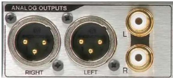
The DAC3 B has one pair of balanced XLR outputs and one pair of unbalanced RCA outputs.
The DAC3 B features high-current output drivers that are capable of driving 300-Ohm loads without an increase in distortion. They are also well suited for driving long cables or high-capacitance loads.
Balanced XLR Analog Line Outputs
The Left and Right balanced outputs use Neutrik™ gold-pin male XLR jacks. The XLR shell and pin 1 (ground) are both directly bonded to the chassis to prevent currents in the internal ground system. This direct bonding also maximizes RF shielding.
The XLR outputs have passive attenuators that allow direct connections to a wide variety of audio devices without a loss of dynamic range. The 10 or 20 dB pads are usually required for direct interfacing to power amplifiers and powered speakers. The DAC3 B ships with the pads disabled (0 dB setting).
A full description of the output attenuators and instructions for configuration is located in the Internal Settings section of this manual.
TIP: Use the 0 dB pad setting when driving Benchmark products and other professional products with XLR inputs that support +24 dBu signal levels. Use the 10 dB pad when driving consumer-grade XLR inputs.
Industry-Standard XLR Wiring
• XLR pin 2 = + Audio Out
• XLR pin 3 = - Audio Out
• XLR pin 1 = Cable Shield
Caution: If the balanced XLR outputs are wired to an unbalanced input (using a special adapter cable), pin 3 must be left floating. Shorting pin 3 to ground will increase the temperature of the output drivers, will increase power consumption, and may cause distortion.
Unbalanced RCA Analog Outputs
The Left and Right unbalanced outputs use female RCA jacks. The ground connections are bonded to chassis ground. This prevents ground loop currents in the internal analog ground.
The RCA output impedance is very low (30 Ohms). This makes these outputs well suited for driving high-capacitance loads and/or high-capacitance cables.
Caution: Mono summing with an RCA 'Y' cable is not recommended as this can produce distortion. Mono summing with a 'Y' cable can be accomplished with the use of a modified cable by implementing a 1k Ohm series resistor in each leg of the 'Y'.
Note: The XLR pads do not have any effect on the level of the RCA outputs.
AC Power-Entry and Fuse Module
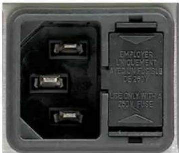
Input Voltage Range
Note: The DAC3 B is equipped with a universal power supply. There is no voltage selection switch. AC voltage range is 88-264 VAC, 47-63 Hz.
Power Cord
Note: The AC power input uses a standard IEC type connector. One USA-compatible power cord is included with DAC3 B converters. IEC style power cords in country-specific configurations are available in your locality.
Caution: Always use a grounded power cord. The DAC3 B is equipped with a standard IEC power entry module. Use an IEC power cord that is equipped with the appropriate connector for your location. Cords are available from your dealer.
Fuses
Caution: For continued fire hazard protection always replace the fuses with the correct size and type (0.5A 250 V Slo-Blo® 5 x 20 mm – Littelfuse® HXP218.500 or equivalent). The fuse drawer includes two fuses. Always replace both fuses at the same time.
Internal Settings
Jumper-Configured Options
The following functions are jumper configured:
- XLR Output Pads
• Digital Pass-Through
Removing Top Cover
The DAC3 cover must be removed to gain access to the jumpers. Do not attempt to remove the faceplate or rear panel.
Caution: The DAC3 contains static sensitive components. Static discharge may cause component failures, may affect the long-term reliability, or may degrade the audio performance. Use a static control wrist strap when changing jumper settings.
- Disconnect AC power by unplugging the power cord at the back of the DAC3.
- Remove the 8 screws holding the cover (4 on each side).
- Do not remove any screws on the front, rear, or bottom panels!
- Never remove the power entry safety cover in the rear corner of the DAC3.
- Connect a static-control wrist strap to the chassis before touching any internal component.
- If a static-control wrist strap is not available, keep one hand on the chassis while moving the jumpers. Avoid touching other components.
XLR Output Pads
The XLR outputs are equipped with low-impedance passive pads that may be used to reduce the output levels while preserving the full dynamic range of the DAC3. The DAC3 ships with the pads disabled (0 dB setting).
Tip: To set the XLR outputs are factory-preset to deliver professional studio levels. Most home installations will require the use of the 10 dB or 20 dB pads.
Tip: Use the factory-default 0 dB setting when driving Benchmark products such as the HPA4, LA4 or AHB2. When directly driving most other power amplifiers (or powered speakers), start with the 10 dB pad setting. If necessary, change the pads so that normal listening levels are achieved when the system volume control is near maximum.
When the output pads are enabled, the output impedance changes slightly, and the maximum recommended XLR cable length is reduced as shown in Table 1. The table assumes a cable capacitance of 32 pF/foot and a maximum allowable loss of 0.1 dB at 20 kHz.
Table 1 - Cable Drive Capability
| Balanced Output Drive Capability: |
| Attenuator Output Maximum Loss in dBSetting (dB) Impedance Cable (ft) at 20 kHz |
| 0 60 680 0.1 |
| 10 425 96 0.1 |
| 20 135 302 0.1 |
| Unbalanced Output Drive Capability: |
| Output Maximum Loss in dB |
| Impedance Cable (ft) at 20 kHz |
| 30 1360 0.1 |
XLR Output Pad Jumpers
Four jumpers on four 6-pin headers (P8, P9, P10, and P11) allow selection of the output level at the XLR jacks. The jumpers are properly configured if a normal playback level is achieved when the VOLUME control is set above the 11 o'clock position.
One pair of 6-pin headers control the attenuation at each XLR jack as follows:
- 0 dB - (Attenuator disabled) - (Jumper plug between pins 1 and 2 of each header) - Factory Default
- -10 dB – (Jumper plug between pins 3 and 4 of each header)
- -20 dB – (Jumper plug between pins 5 and 6 of each header)
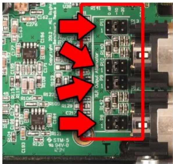
Figure 1 - Attenuators set to -10 dB
Digital PASS-THROUGH Function
The digital PASS-THROUGH function can be enabled by moving two jumpers. When the PASS-THROUGH function is enabled, D4 cannot be selected as an input. Any other selected digital input will be routed to both the internal D/A converter and to output D4. The digital output at D4 is buffered, but is not processed. Many digital audio formats can be passed through to D4 (even when these formats cannot be decoded by the DAC3).
Digital PASS-THROUGH Jumpers
To enable the PASS-THROUGH function, move both P14 jumpers toward the faceplate as shown in Figure 2. Once the jumpers are moved into the positions shown in Figure 2, D4 is configured as a digital audio output.
By default, D4 functions as a digital input and the DAC3 is shipped with the jumpers set according to Figure 3 (both jumpers toward the rear panel).
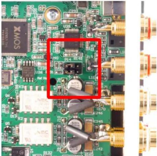
natural_image
Close-up of a green printed circuit board with various electronic components and connectors, no visible text or symbols.Figure 2 - Digital PASS-THROUGH Enabled
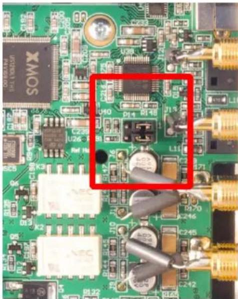
natural_image
Close-up of a green printed circuit board with electronic components and connectors (no readable text or symbols)
natural_image
Close-up of three identical metallic cylindrical components with no visible text or symbolsFigure 3 - Digital PASS-THROUGH Disabled (Factory Default)
Rack Mounting
The DAC3 B is available with or without rack mount ears. The chassis is one half the width of a standard rack and occupies a one rack-unit height.
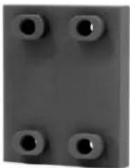
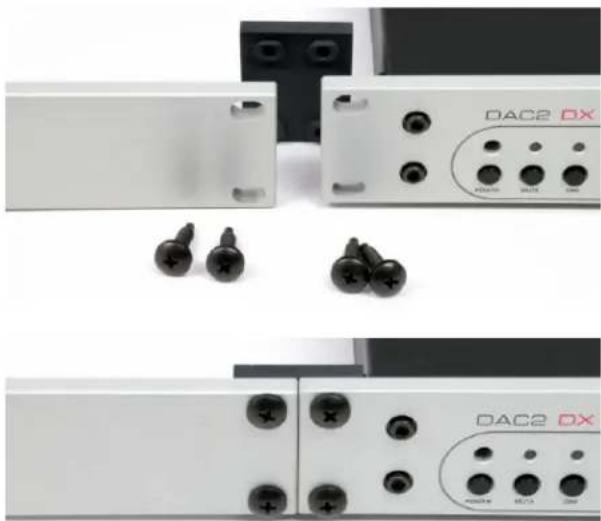
Units without rack-mount ears will require a mounting tray. Units with rack-mount ears will require a Rack-Mount Coupler which joins the DAC3 to another 12 -wide Benchmark product or to a Blank Plate.
The Rack-Mount Coupler, Rack-Mount Tray and 12 -Wide Blank Plate are available from Benchmark.
Benchmark Rack-Mount Coupler
natural_image
Close-up of a gray rectangular object with four circular holes, no visible text or symbols.The Rack-Mount Coupler joins two 1/2-wide 1-RU products. Both products must be equipped with rack ears. Order with an optional Blank Plate if only one unit will be mounted in the rack.
No tray is required when using the Rack-Mount Coupler.
natural_image
Close-up of three white DAC2 DX electronic devices with black screw connectors and indicator lights, no visible text or symbols on the devices themselves.Benchmark Rack Mount Tray
natural_image
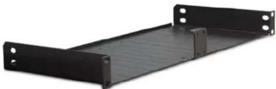
Black metal shelf panel with mounting holes and a flat base (no text or symbols visible)The Benchmark Rack Mount Tray mounts up to two 12 -wide Benchmark products in a single race space. The tray accepts any combination of 12 -wide Benchmark products (with or without rack-mount type faceplates). A blank plate can be added when only one unit is installed in the rack mount tray.
Benchmark 1/2-Wide Blank Plate
natural_image
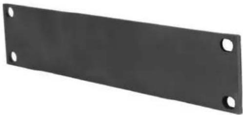
Black rectangular metal plate with four circular holes, no text or symbols visibleThe Benchmark 12 -Wide Blank Plate is a 12 -wide 1-RU anodized aluminum panel for filling an unused 12 -wide slot. It is available in black or silver. The silver panel includes an engraved Benchmark logo.

Visit BenchmarkMedia.com for a complete selection of cable, accessories, and replacement parts.
DAC1, DAC2 and DAC3 Family History
The pristine audio performance of the award-winning DAC1 made it the 'Benchmark' of stand-alone D/A converters. The DAC1 USB, DAC1 PRE, and DAC1 HDR added many features to the basic DAC1 platform. Benchmark converters are in use in many of the world's top studios.
The following is a brief overview of the various Benchmark DAC1, DAC2 and DAC3 models:
DAC1 Series
DAC1
Benchmark's original DAC1 converter.
The DAC1 features included:
• Three digital inputs
- XLR outputs with passive pads
- RCA outputs
- Analog volume control
- HPA2™ headphone amplifier
- UltraLock™ jitter-attenuation system
DAC1 USB
The DAC1 USB introduced these improvements:
- AdvancedUSB™ computer input
- Mute switch on the left headphone jack
- Two headphone gain ranges
- High-current LM4562/LME49860 output stages - designed to drive difficult loads
- Lower output impedances
Benchmark's AdvancedUSB™ computer input was the first USB audio interface to support 96 kHz audio without the need to install special drivers.
DAC1 PRE
The DAC1 PRE added these improvements:
• Three coaxial digital inputs
• Three Headphone Gain Ranges
• LM4562/LME49860 opamps throughout
- Premium bulkhead-mounted RCA connectors
In order to provide room for the analog inputs, we removed the XLR digital input and replaced it with two additional coaxial digital inputs.
DAC1 HDR
The DAC1 HDR added:
- IR Remote Control
- HDR-VC™ (high dynamic range volume control).
The HDR-VC™ features a custom-made, motor-driven Alps potentiometer. The motor-driven control provides the audio performance of a manual control while adding the convenience of remote control.
DAC2 Series
DAC2 HGC
The DAC2 HGC maintains the familiar 12 -wide DAC1 form factor, but the entire product was redesigned from the ground up.
The DAC2 HGC features:
• Four 32-bit converters per channel
- Native 24-bit/192kHz PCM conversion
- Native 64X DSD conversion
• High-headroom digital processing
- UltraLock2™ jitter attenuation
- Multi-mode asynchronous USB audio input
• Sample rate and word length displays
- Polarity control
• Home theater bypass
• Digital pass-through
• Bi-directional 12V trigger
- Two stereo analog inputs
• Three stereo analog outputs
- Two optical inputs
• High-efficiency low-noise power supplies
DAC2 L
The DAC2 L is identical to the DAC2 HGC except that the DAC2 L has no headphone amplifier.
DAC2 D
The DAC2 D is identical to the DAC2 HGC except that the DAC2 D has no analog inputs and no 12V trigger.
DAC2 DX
The DAC2 DX replaced the DAC2 D. The new model added an XLR digital input and the 12V trigger. It also added a second output bus so that one set of outputs could be placed in calibrated mode while the other was controlled by the volume knob.
DAC3 Series
On the surface, the DAC3 series converters look exactly like the DAC2 converters. They have the same controls, the same connectors, and even the similar-looking circuit boards. The difference is that many critical components and systems have been upgraded. The new DAC3 delivers lower THD, improved digital filtering, and faster PLL lock times.
The firmware, digital signal processing, and UltraLock™ clock system have all been upgraded in the new DAC3. Most notably, the DAC3 series includes the new ES9028PRO D/A converter. This groundbreaking D/A converter IC offers several significant improvements over the ES9018 converter used in the DAC2 series. Until the ESS PRO series was introduced, the ES9018 was the highest performance D/A converter IC available. The ESS PRO series converters are now setting this benchmark. The Benchmark DAC3 is one of the first products to feature this new 32-bit D/A converter.
Benchmark's ultra-clean analog stages, low-jitter UltraLock3™ clock system, and high-headroom DSP leverage the full capabilities of the new ESS PRO series converters.
DAC3 vs. DAC2
The DAC3 series adds the following improvements over the DAC2 series:
• ESS SABRE-PRO D/A Conversion
- UltraLock3™ clock system
- Instantaneous lock
- Instantaneous input switching
• THD reduction system
- 2nd-harmonic compensation
- 3rd-harmonic compensation
- Improved digital filters
- Lower passband ripple
- Flatter frequency response
• Higher maximum output level
- Increased Dynamic Range
Benchmark Technologies
Native DSD Conversion
The digital coaxial inputs and the USB Audio 2.0 input on the DAC3 support native DSD conversion. DoP 1.1 DSD encapsulation is automatically detected on all digital inputs. The system seamlessly switches to native DSD conversion when DoP is detected. DoP 1.1 DSD encapsulation is supported by many media players. DSD downloads are now available from several sources.
Visit our website for an up-to-date list of DSD and PCM high resolution download sites.
High Headroom DSP
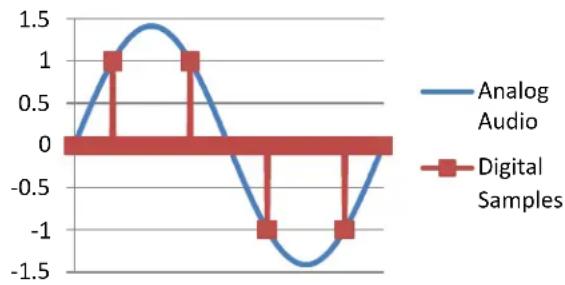
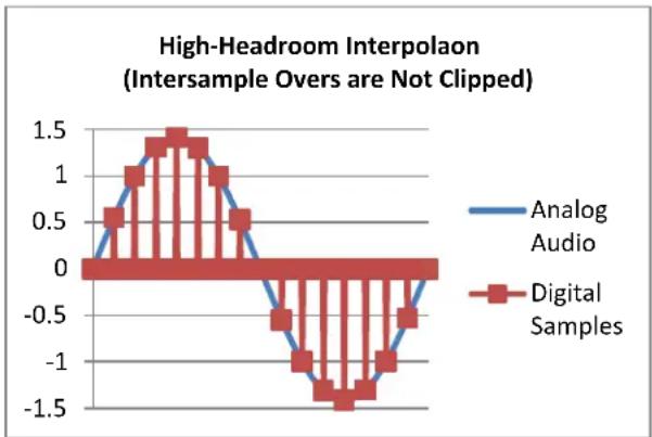
All of the digital processing in the DAC3 is designed with a headroom of 3.5 dB above 0 dBFS. A sinusoid that just reaches the maximum positive and negative digital codes has a level of 0 dBFS. If the peaks of the sinusoid occur between samples, higher signals can be captured without clipping. For a pure tone, the maximum intersample peak that can be represented by a PCM system is +3.01 dBFS.
Benchmark's high-headroom DSP can handle intersample peaks without overloading or clipping. Intersample peaks are cleanly rendered by the DAC3 and are delivered to the analog outputs without clipping or distortion. Very few D/A converters can make this claim!
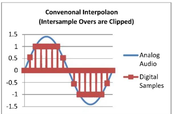
In most D/A conversion systems, intersample peaks cause overloading of the upsampling interpolators and digital filters that are found in all sigma-delta converters. When overloads occur, bursts of non-harmonic distortion are produced. These bursts of high-frequency distortion may occur many times per second and may add a false brightness and harshness to the sound. This defect impacts PCM formats but does not impact 1-bit DSD formats. The absence of intersample clipping may explain some people's preference for DSD. The DAC3 delivers clean PCM
conversion that meets or exceeds the clarity of DSD.
Intersample Overs
(1 = Maximum Digital Code)
line
| Time | Analog Audio | Digital Samples | |------|--------------|-----------------| | 0 | 0 | 0 | | 1 | 1 | 1 | | 2 | 1 | 1 | | 3 | 0 | 0 | | 4 | -1 | -1 | | 5 | -1 | -1 |Intersample overs are common in low sample rate (44.1 kHz and 48 kHz) commercial releases. Due to the mathematics and the bandwidth of typical input signals, intersample overs are less of a problem in high sample rate recordings. The reason for this is that the worst-case (+3.01 dB) intersample overs occurs for pure tones that are exactly 1/4 of the sample rate (as shown in the figure above). At the 44.1 kHz CD sample rate, the worst case occurs at 11.025 kHz. It turns out that many recordings have substantial peaks near this frequency. In contrast, at a sample rate of 88.2 kHz, the worst-case intersample overs occur at a frequency of 22.1 kHz where most musical sources have insufficient energy to produce significant intersample overs. The 88.2 kHz sample rate is still susceptible to intersample overs, but the magnitude of the worst-case overs tends to be much lower. For example, at 1/8th of the sample rate (11.025 kHz), the maximum intersample peak is about +0.66 dB instead of the 3.01 dB worst case at a sample rate of 44.1 kHz.
The biggest advantage of higher sample rates may be the immunity to intersample overs. If higher sample rates sound better, this difference may be entirely due to the absence of DSP overloads caused by intersample overs. Benchmark's high-headroom DSP renders low sample rates with the clarity and detail normally associated with high sample rates.
line
| x | Analog Audio | Digital Samples | | ---- | ------------ | --------------- | | 0 | 0.0 | 0.0 | | 1 | 1.0 | 1.0 | | 2 | 0.5 | 0.5 | | 3 | 0.0 | 0.0 | | 4 | -1.0 | -1.0 | | 5 | -1.5 | -1.5 |PCM systems can accurately capture peaks that exceed 0 dBFS, but these peaks will overload the oversampling interpolators in most delta-sigma D/A converters. The solution is not to eliminate the interpolation process; the solution is to build interpolators with more headroom.
line
| X Value | Analog Audio | Digital Samples | | ------- | ------------ | --------------- | | 0 | 0.0 | 0.0 | | 1 | 0.5 | 0.5 | | 2 | 1.0 | 1.0 | | 3 | 1.5 | 1.5 | | 4 | 1.0 | 1.0 | | 5 | 0.5 | 0.5 | | 6 | 0.0 | 0.0 | | 7 | -0.5 | -0.5 | | 8 | -1.0 | -1.0 | | 9 | -1.5 | -1.5 | | 10 | -1.0 | -1.0 | | 11 | -0.5 | -0.5 | | 12 | 0.0 | 0.0 |The interpolation process is absolutely necessary to achieve 24-bit state-of-the-art conversion performance. Unfortunately, intersample overs cause clipping in most interpolators. This clipping produces distortion products that are non-harmonic and non-musical. We believe these broadband distortion products often add a harshness or false high-frequency brightness to digital reproduction. The DAC3 avoids these problems by maintaining at least 3.5 dB of headroom in the entire conversion system. We believe this added headroom is a groundbreaking improvement.
32-bit SABRE-PRO D/A System
Four balanced 32-bit D/A converters deliver audio to Benchmark's low-impedance current to voltage converters. The 4:1 redundancy reduces noise by 6 dB. The redundancy also reduces the THD. The conversion system at the core of the DAC3 is as good as it gets. The analog circuits that follow the D/A converter are carefully designed. Benchmark has leveraged its long history of building reference analog audio equipment to create an outstanding output stage.
Diagnostic Displays
Ever wonder why that 192 kHz 24-bit download on your computer just doesn't sound right? Your media player or computer may be downsampling to 44.1 kHz and/or truncating to 16-bits. Many media players and computer operating systems apply poor-quality sample rate conversion and/or truncation. Fortunately these problems can be eliminated with the selection of a good frequency-agile media player.
Many disk players also downsample all sources to 44.1/16. This processing can do significant damage to the audio quality.
The sample-rate and word-length displays on the DAC3 confirm the proper operation of your disk player, media player, and computer.
Bi-Directional 12 Volt Trigger
Benchmark has re-invented the 12 volt trigger. The trigger connection on the DAC3 can be used as an input or output or both, and is compatible with any common 12 volt trigger input or output. The trigger can be used to turn a power amplifier on or off automatically. The DAC3 will also respond to a 12 volt trigger and follow the actions of another audio component.
Benchmark components can communicate bidirectionally on the trigger I/O ports. This bidirectional communication provides greater flexibility. In a given system, the power
button on any Benchmark device can be used to start or stop the entire audio system in a sequenced manner.
Distributed Power Regulation
To achieve the lowest possible noise, the DAC3 uses distributed power supply regulation. Each critical subsystem has at least one dedicated low-noise voltage regulator.
We have created a discrete ultra low-noise regulator for the ES9028PRO D/A converter. This Benchmark exclusive feature improves the noise performance of the already-outstanding ES9028PRO.
Differential Amplifiers
Differential amplifiers remove common-mode distortion components from the D/A converter outputs. This feature is critical for achieving low-distortion in down-stream devices. Benchmark addresses common-mode distortion so that it will not cause distortion in power amplifiers and other connected devices. Common-mode distortion can cause audible distortion while escaping the scrutiny of an audio analyzer. The balanced and unbalanced outputs on the DAC3 deliver very similar performance.
Many D/A converters omit the differential amplifiers after the converters. Specifications usually ignore common-mode distortion. A balanced signal with high common-mode distortion can measure just fine when feeding a precisely balanced input on a high-quality audio analyzer. However, any imbalance in a downstream device will expose the common-mode distortion.
Jitter-Immune UltraLock3™
UltraLock3 ^™ is an improved version of the UltraLock2 ^™ clock system used in the DAC2. The new UltraLock3 ^™ system provides faster lock times than the older UltraLock2 ^™ and UltraLock ^™ systems. The DSP processing is 32-bits, DSP headroom is
3.5 dB, sample rate is 211 kHz, and jitter-induced distortion and noise is at least 160 dB below the level of the music - well below the threshold of hearing. Benchmark's
UltraLock3™ system eliminates all audible jitter artifacts.
The Importance of Eliminating Jitter
Accurate 24-bit audio conversion requires a very low-jitter conversion clock. Jitter can very easily turn a 24-bit converter into a 16-bit converter (or worse). There is no point in buying a 24-bit converter if clock jitter has not been adequately addressed.
Jitter is present on every digital audio interface. This type of jitter is known as 'interface jitter' and it is present even in the most carefully designed audio systems. Interface jitter accumulates as digital signals travel down a cable from one digital device to the next. If we measure interface jitter in a typical system we will find that it is 10 to 10,000 times higher than the maximum allowable level for accurate 24-bit conversion. Fortunately, interface jitter has absolutely no effect on the audio unless it influences the conversion clock in an analog-to-digital converter (A/D), the conversion clock in a digital-to-analog converter (D/A), or the rate estimator in an asynchronous sample rate converter (ASRC).
Many converters use a single-stage Phase Lock Loop (PLL) circuit to derive their conversion clocks from AES/EBU, wordclock, or superclock reference signals. Single-stage PLL circuits provide some jitter attenuation above 5 kHz but none below 5 kHz. Unfortunately, digital audio signals often have their strongest jitter components at 2 kHz. Consequently, these converters can achieve their rated performance only when driven from very low jitter sources and through very short cables. It is highly unlikely that any converter with a single-stage PLL can achieve better than 16 bits of performance in a typical installation. Specified performance may be severely degraded in most installations.
Better converters often use a two-stage PLL circuit to filter out more of the interface jitter. In theory, a two-stage PLL can remove enough of the jitter to achieve accurate 24-bit conversion (and some do). However, not all two-stage PLL circuits are created equal. Many two-stage PLLs do not remove enough of the low-frequency jitter. In addition, two-stage PLL circuits often require several seconds to lock to an incoming signal. Two-stage PLL circuits may fail to lock when jitter is too high, or when the reference sample frequency has drifted.
UltraLock ^™ converters exceed the jitter attenuation performance of two-stage PLL converters while achieving near instantaneous lock time. They are free from the slow-lock and no-lock problems that can plague two-stage PLL designs. UltraLock ^™ converters have extremely high immunity to interface jitter under all operating conditions.
The UltraLock™ system is so effective that no jitter-induced artifacts could be detected using an Audio Precision System 2 Cascade test set while the inputs to the DAC3 were exposed to high levels of interface jitter. The measurement limits included the ability to detect artifacts as low as -144 dBFS, but none could be detected, even while applying jitter amplitudes as high as 12.75 UI, over a frequency range of 2 Hz to 200 kHz. Any AES/EBU signal that can be decoded by the AES/EBU receiver in the DAC3 will be reproduced without the addition of any measurable jitter artifacts.
Benchmark's UltraLock™ technology eliminates jitter-induced performance problems. UltraLock™ technology isolates the conversion clock from the digital audio interface clock. Jitter on a D/A digital audio input, or an A/D reference input can never have any measurable effect on the conversion clock of an UltraLock™ converter. In an UltraLock™ converter, the conversion clock is never phase-locked to a reference clock. Instead the converter oversampling-ratio is varied with extremely high precision to achieve the proper phase relationship to the reference clock. The clock isolation of the
UltraLock™ system ensures that interface jitter can never degrade the quality of the audio conversion. Specified performance is consistent and repeatable in any installation with cables of any quality level!
How does conversion clock jitter degrade converter performance?
Problem #1: Jitter phase-modulates the audio signal. This modulation creates sidebands (unwanted tones) above and below every tone in the audio signal. Worse yet, these sidebands are often widely separated from the tones in the original signal.
Jitter-induced sidebands are not musical in nature because they are not harmonically related to the original audio. Furthermore, these sidebands are poorly masked (easy to hear) because they can be widely separated above and below the frequencies of the original audio tones. In many ways, jitter induced distortion resembles intermodulation distortion (IMD). Like IMD, jitter induced distortion is much more audible than harmonic distortion, and more audible than THD measurements would suggest.
Jitter creates 'new audio' that is not harmonically related to the original audio signal. This 'new audio' is unexpected and unwanted. It can cause a loss of imaging, and can add a low and mid frequency 'muddiness' that was not in the original audio.
Jitter-induced sidebands can be measured using an FFT analyzer while the converter plays a pure high-amplitude tone. We typically use a full-scale 10 kHz test tone to test for the presence of jitter-induced side bands (see Graph 14). This FFT shows that the DAC3 is free from any jitter-induced sidebands to a measurement limit of about -144 dB relative to the level of the test tone. The graph plots the output spectrum of the DAC3 when exposed to 31 different jitter frequencies ranging from 100 Hz to 100 kHz. All 31 output spectra are identical and are free from any signs of jitter-induced distortion.
Problem #2: Jitter can severely degrade the anti-alias filters in an oversampling converter. This is a little known but easily measurable effect. Most audio converters operate at high oversampling ratios. This allows the use of high-performance digital anti-alias filters in place of the relatively poor performing analog anti-alias filters. In theory, digital anti-alias filters can have extremely sharp cutoff characteristics, and very few negative effects on the in-band audio signal. Digital anti-alias filters are usually designed to achieve at least 100 dB of stop-band attenuation. But, digital filters are designed using the mathematical assumption that the time interval between samples is a constant. Unfortunately, sample clock jitter in an A/D or D/A varies the effective time interval between samples. This variation alters the performance of these carefully designed filters. Small amounts of jitter can severely degrade stop-band performance, and can render these filters useless for preventing aliasing.
The obvious function of a digital anti-alias filter is the removal of audio tones that are too high in frequency to be represented at the selected sample rate. The not-so-obvious function is the removal of high-frequency signals that originate inside the converter box, or even originate inside the converter IC. These high-frequency signals are a result of crosstalk between digital and analog signals, and may have high amplitudes in a poorly designed system. Under ideal (low jitter) conditions, the digital anti-alias filter may remove most of this unwanted noise before it can alias down into lower (audio) frequencies. These crosstalk problems may not become obvious until jitter is present.
Stop-band attenuation can be measured very easily by sweeping a test tone between 24 kHz and at least 200 kHz while monitoring the output of the converter.
Put UltraLock™ converters to the test:
We encourage our customers to perform the above tests on UltraLock ^™ converters (or let your ears be the judge). There will be absolutely no change in performance as jitter is added to any digital input on an UltraLock™ converter. Try the same tests on any converter using conventional single or two-stage PLL circuits. Tests should be performed with varying levels of jitter and with varying jitter frequencies. The results will be very enlightening. Jitter related problems have audible (and measurable) effects on A/D and D/A devices. Practitioners of Digital Audio need to understand these effects.
Is it possible to eliminate all of the effects of jitter in an entire digital audio system?
Interface jitter will accumulate throughout even the most carefully designed digital audio system. Fortunately, interface jitter can only degrade digital audio if it affects the sampling circuit in an analog-to-digital or digital-to-analog converter. Any attempt to cure jitter outside of an A/D or D/A will prove expensive and, at best, will only partially reduce jitter-induced artifacts. Dedicated clock signals (word clock, and super clock, etc.) are often distributed to A/D converters and D/A converters in an attempt to reduce jitter. Again, these are only partial solutions because jitter even accumulates in these clock distribution systems. Furthermore, a poor quality master clock generator can degrade the performance of the entire system (if converter performance is dependent upon reference clock quality). Jitter-free A/D and D/A converters are the only true insurance against the ill effects of jitter. UltraLock™ converters are jitter-immune under all operating conditions (they will never add audible jitter-induced artifacts to an audio signal).
What UltraLock™ converters cannot do:
UltraLock™ converters cannot undo damage that has already been done. If an A/D with a jitter problem was used to create a digital audio signal, then there is nothing that can be done to remove the jitter-induced distortion that happened inside the A/D converter. Jitter-induced sidebands are extremely complex and cannot be removed with any existing audio device. Therefore, it is very
important to attack jitter at both ends of the audio chain. The DAC3 is a great start, as it will allow accurate assessment of various A/D converters. It is impossible to audibly evaluate A/D performance without a good D/A. The consistent performance delivered by the DAC3 eliminates one major variable - jitter.
Multi-Mode Asynchronous USB Audio
Plug it in and Start Listening... Immediately
Benchmark's Advanced USB Audio system supports the industry standard USB Audio 1.1 and USB Audio 2.0 protocols. These audio protocols should not be confused with USB port speeds. The USB Audio 1.1 protocol requires at least a USB 1.0 (Full Speed) port. USB Audio 2.0 requires at least a USB 2.0 (High Speed) port.
Benchmark's USB Audio 1.1 and USB Audio 2.0 modes are frequency agile. This means that the sample rate is controlled by the computer. The DAC3 will follow sample rate changes initiated by the computer and/or the media playback software.
Tip: The USB Audio 1.1 protocol will run on any USB port, but if it is run on a USB 1.0 (Full Speed) port, it will require all of the available bandwidth to support 96 kHz sample rates. If a USB 1.0 port is the fastest port available, make sure that there are no other devices sharing the USB hub that services the port. When possible, connect the DAC3 to a port that supports USB 2.0 or higher.
Tip: The USB Audio 2.0 protocol is required for sample rates above 96 kHz. This protocol will not run on USB 1.0 ports. When possible, connect the DAC3 to a port that supports USB 2.0 or higher.
Asynchronous USB
In all modes the USB communications are asynchronous. An ultra low jitter conversion clock is generated inside the DAC3. The asynchronous USB interface pulls data from the computer without using computer-generated clocks. The D/A conversion in the DAC3 is completely isolated by the asynchronous USB interface and by the UltraLock3™ jitter-attenuation system.
The DAC3 has a low-jitter master clock which controls the transfer of audio data from the computer to the USB sub-system. The computer asynchronously transfers audio data to a buffer in the DAC3. The contents of the buffer are then asynchronously transferred to the D/A conversion sub-system. This second asynchronous transfer eliminates any traces of jitter that accumulate as the data is transferred between the USB and conversion subsystems. No traces of jitter-induced distortion are detectable at our measurement limits (about -144 dBFS). This truly represents the state-of-the-art. Enjoy the convenience of computer playback without compromise.
The Asynchronous USB system supports USB Audio 2.0 for high-resolution 192kHz, and DSD playback. No drivers are required for MAC operating systems. An easy-to-install driver adds 192 kHz and DSD capabilities to Windows operating systems.
The asynchronous driverless USB Audio 1.1 mode supports sample rates up to 96 kHz. This USB mode can be selected from the front panel or from the remote control. The driverless USB Audio 1.1 mode allows quick plug-and-play connections to Windows, MAC, iOS, and Linux operating systems without installing drivers. Just plug in the USB, and the DAC3 becomes an available audio device. In many cases, audio will automatically be routed to the newly connected device. If not, it can be selected as the current or default playback device.
The industry-standard USB Audio Mode 2.0 mode is not yet natively supported by the current Windows operating systems. For this reason, a driver is required for Windows operating systems. The driver supports Windows XP, Vista, or 7, 8 and 10. This driver
is required for DSD and sample rates above 96 kHz when using Windows.
The USB subsystem is computer powered (through the USB cord) and it remains active when the DAC3 is powered down. This feature prevents interruptions to the
computer playback operations and eliminates the need to reconfigure the computer every time the converter is turned on.
The Windows USB Audio 2.0 driver is available at: BenchmarkMedia.com/drivers
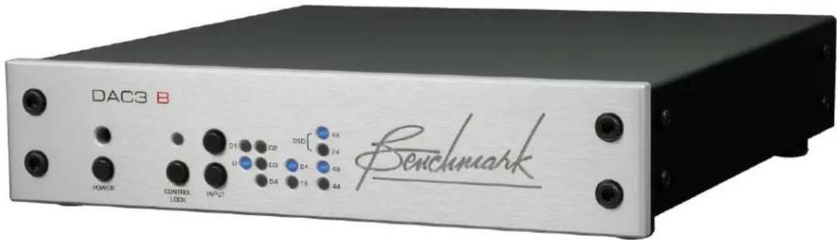
USB Driver Installation
Windows Operating Systems
Note: The DAC2/DAC3 driver is available for download at: BenchmarkMedia.com/drivers
Note: To provide full backward and forward compatibility, the DAC3 uses the DAC2 USB drivers. This prevents the need to install two different sets of drivers. Please note that the DAC3 USB input will be identified as "Benchmark DAC2" in your computer control panels. This is intentional.
Before you install the driver, make sure the USB cable is unplugged.
- In the DAC2 Driver folder, double click "setup.exe."
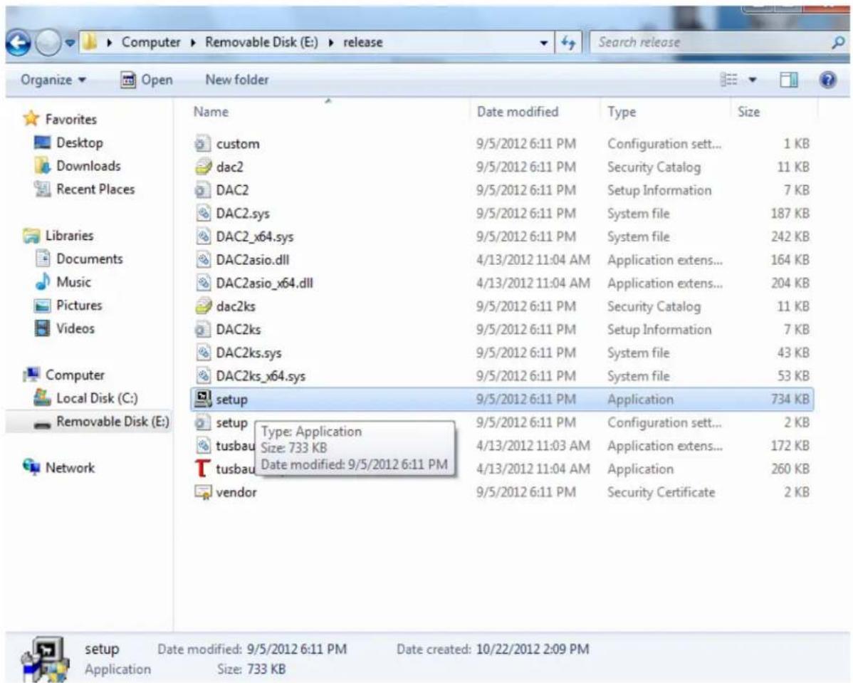
- A welcome screen will pop-up. Click "Next."
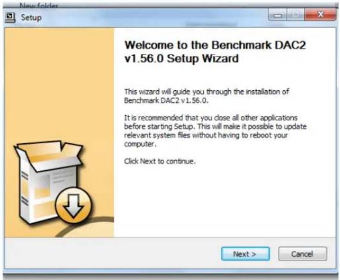
-
When you see the following screen, turn on the DAC3, plug in the USB cable, and select the USB input on the DAC3. By default, the DAC3 is shipped in USB Audio 1.0 mode. Do not proceed to the next step until the USB Audio 2.0 mode has been enabled. You can enable the USB Audio 2.0 mode using one of the following two methods:
-
METHOD 1 - REMOTE CONTROL: Using your remote control, press and hold USB button for 3 seconds (the 4X light should flash once). If the 2X light flashes instead of the 4X light, repeat this step.
- METHOD 2 - FRONT PANEL: From the front panel, simultaneously press and hold both INPUT buttons for three seconds (the 4X light should flash once when selecting the USB input). If the 2X light flashes instead of the 4X light, repeat this step.
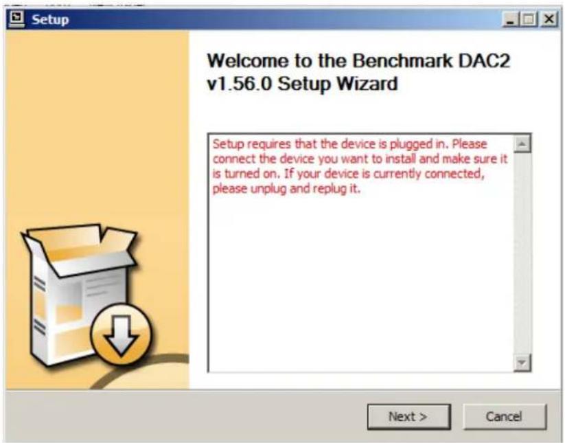
- You will now be prompted to select a location to install the driver. It will default to your Program Files folder. If you wish to install it another location, you can change the location. We suggest keeping it in the default location. Click "Install".
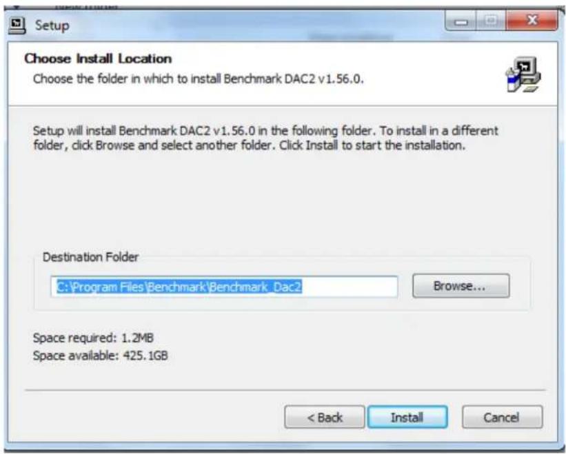
- When the installation begins you will see the following screen. Please be patient while the driver installs. Installation may require several minutes.
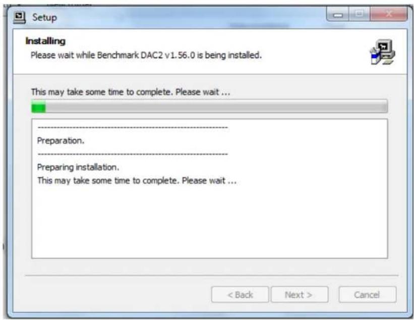
- When the installation finishes a message at the top will say "Installation Complete." Click "Next" to continue.
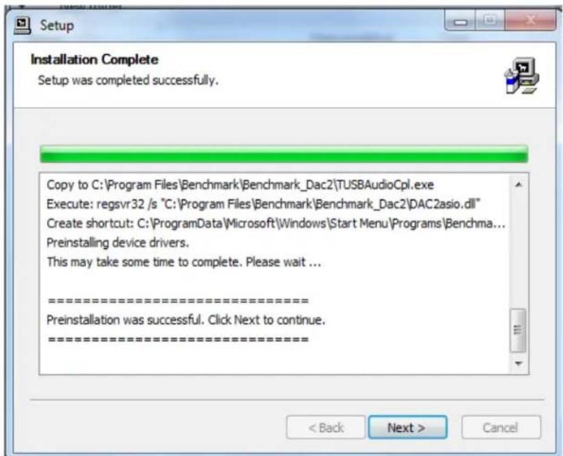
- Click "Finish." The Setup will close automatically. This completes the installation process. You can now enjoy music over the USB Audio 2.0 connection at sample rates up to 192 kHz. DSD can also be played in DoP 1.1 format.
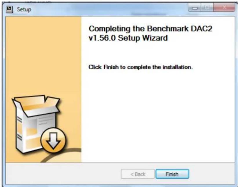
Performance Graphs
Audio Precision
DAC3 - FFT Idle Channel Noise at Max Gain, 0 dBr = 0 dBFS = 27.5 dBu
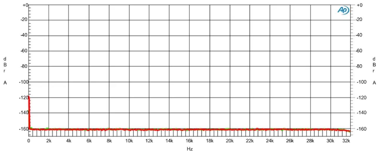
line
| Hz | d B r | d B r | | ---- | ----- | ----- | | 0 | -160 | -160 | | 2k | -160 | -160 | | 4k | -160 | -160 | | 6k | -160 | -160 | | 8k | -160 | -160 | | 10k | -160 | -160 | | 12k | -160 | -160 | | 14k | -160 | -160 | | 16k | -160 | -160 | | 18k | -160 | -160 | | 20k | -160 | -160 | | 22k | -160 | -160 | | 24k | -160 | -160 | | 26k | -160 | -160 | | 28k | -160 | -160 | | 30k | -160 | -160 | | 32k | -160 | -160 || ColorSweep Trace Line Style Thick Data Axis Comment | ||
| 1 1 Green Solid 4 | Fft.Ch.1 Ampl Left | |
| 1 2 Red Solid 4 | Fft.Ch.2 Ampl Right | |
DAC3 - FFT Idle Channel Noise.at27
Graph 1 - FFT Idle Channel Noise
The extraordinary performance of the DAC3 is demonstrated by the FFT plot shown above. There is no sign of any AC hum, there are no idle tones, and there are no spurious tones detected at a measurement limit of -160 dBFS.
The rise at 0 Hz is normal in an FFT analysis and is not an indication of noise. This 32k point FFT analysis uses a Blackman-Harris window with 16x power averaging, and spans a frequency range of DC to 32 kHz.
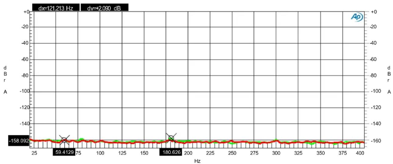
line
| Frequency (Hz) | Amplitude (dB) | | -------------- | -------------- | | 59.4 | -158.092 | | 180.6 | -158.092 || ColorSweep Trace Line Style Thick Data Axis Comment Cursor1 Cursor2 | |||||||||
| 1 | 1 | Green | Solid | 4 | Fft.Ch.1 Ampl | Left | Left Channel | *-160.182 dBr | *-158.092 dBr |
| 1 | 2 | Red | Solid | 4 | Fft.Ch.2 Ampl | Right | Right Channel | -159.850 dBr A | -160.611 dBr A |
DAC3 - FFT Idle Channel Noise - Low Frequency.at27
Graph 2 - Low Frequency FFT - AC Line-Related Hum
The DAC3 shows no evidence of AC line-related hum to a measurement limit of about -160 dBFS. The cursors are placed at 60 Hz and 180 Hz (frequencies where we would expect to see interference from the 60 Hz AC input. In the idle channel noise spectrum there is absolutely no sign of any AC hum! At full output, these line-related frequencies still measure better than -133 dB (see Graph 4).
This graph demonstrates one of the advantages of switching power supplies. The switching power supplies in the DAC3 operate at frequencies above the audio band and this eliminates the strong line-frequency magnetic fields that would have been created by line-frequency power transformers.
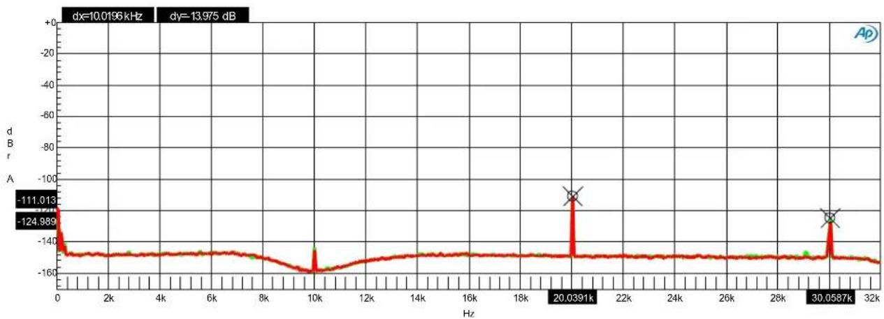
line
| Frequency (Hz) | Amplitude (dB) | | -------------- | -------------- | | 0 | -111.013 | | 10k | -124.989 | | 20.0391 | -111.013 | | 30.0587 | -124.989 || ColorSweep Trace Line Style Thick Data Axis Comment Source 2 Cursor1 Cursor2 | ||||||||
| 1 | 2 | Green | Solid | 4 | Ft.Ch.1 Ampl | Left | :1.00000 =Swr.Ch. A Input | *-111.013 dBr *-124.989 dBr |
| 2 | 2 | Red | Solid | 4 | Ft.Ch.1 Ampl | Left | :2.00000 =Swr.Ch. A Input | -111.241 dBr A -127.362 dBr A |
DAC3 - FFT 10 kHz.at27
Graph 3 - FFT 10 kHz
The 10 kHz FFT analysis is an excellent test for detecting sample clock jitter. Jitter will create sidebands (unwanted tones) above and below the 10 kHz test tone. For example, a jitter frequency of 1 kHz would create two sideband tones; a lower sideband at 9 kHz, and an upper sideband at 11 kHz. Similarly, a jitter frequency of 2 kHz would produce sideband tones at 8 kHz and 12 kHz. The above plot shows no evidence of jitter-induced sidebands to a measurement limit of about -149 dB relative to the amplitude of the 10 kHz test tone.
Note the very low harmonic distortion; the 2nd harmonic (20 kHz) measured -111 dB, and the 3rd harmonic (30 kHz) measured -125 to -127 dB.
This 32k point FFT analysis uses a Blackman-Harris window with 16x power averaging. The 10 kHz fundamental has been removed by a notch filter in order to increase the resolution of the A/D converter in the AP2722 test set.
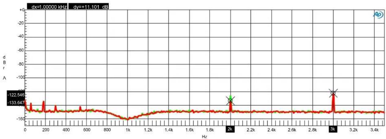
line
| Frequency (Hz) | Amplitude (dB) | | -------------- | -------------- | | 2k | -133.647 | | 3k | -122.546 || ColorSweep Trace Line Style Thick Data Axis Comment Source 2 Cursor1 Cursor2 | |||||||||
| 1 | 2 | Green | Solid | 4 | Ft.Ch.1 Ampl | Left | Left Channel : 1.00000 =Swr.Ch. A Input | -125.680 dBr A | -123.514 dBr A |
| 2 | 2 | Red | Solid | 4 | Ft.Ch.1 Ampl | Left | Right Channe: 2.00000 =Swr.Ch. A Input | *-133.647 dBr | *-122.546 dBr |
DAC3 - FFT 1 kHz.at27
Graph 4 - FFT 1 kHz
The 1 kHz FFT analysis demonstrates the very low harmonic distortion of the DAC3. The second harmonic distortion (2 kHz) measured better than -126 dB, while the 3rd harmonic distortion measured better than -122 dB relative to the amplitude of the 1 kHz test tone.
This 32k point FFT analysis uses a Blackman-Harris window with 16x power averaging. The 1 kHz fundamental has been removed by a notch filter in order to increase the resolution of the A/D converter in the AP2722 test set.
Note that under this full-output condition, the AC line-related hum frequencies (60 Hz, 180 Hz, and 240 Hz) measure better than - 133 dB.
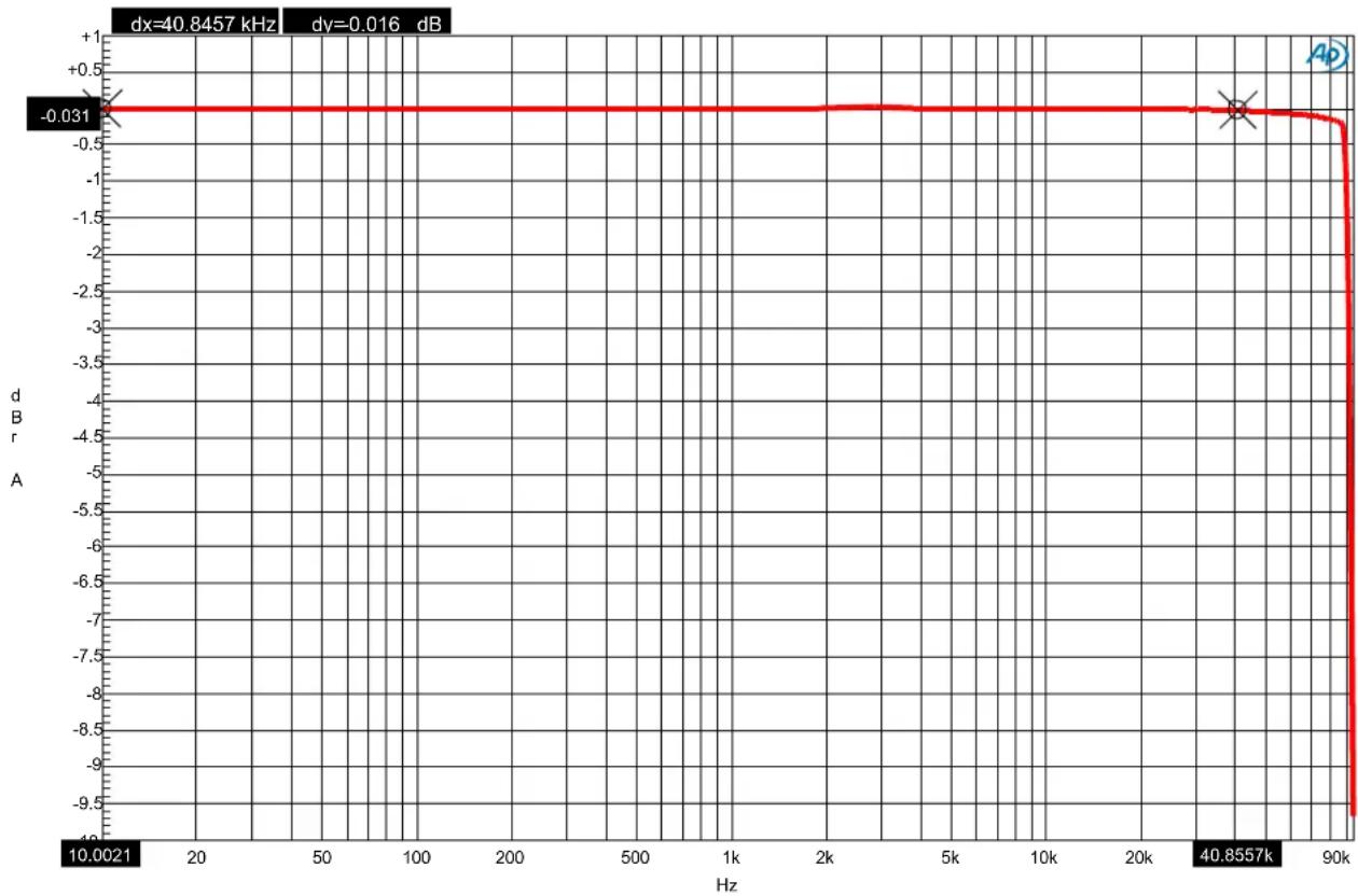
line
| Frequency (Hz) | Value (dB) | | -------------- | ---------- | | 10.0021 | -0.031 | | 40.8557 | -0.031 || ColorSweep Trace Line Style Thick Data Axis Comment Cursor1 Cursor2 | |||||||||
| 1 | 1 | Red | Solid | 4 | Anlr.Level A | Left | ^-0.015 | dBr | ^-0.031 dBr |
DAC3 - Frequency Respons e.at27
Graph 5 - Frequency Response
This plot demonstrates the ruler-flat frequency response of the DAC3. Note that the frequency response measures - 0.015 dB at 10 Hz and -0.031 dB at 40 kHz. The extreme low-frequency extension of the DAC3 virtually eliminates the phase shifts that often occur at low frequencies (near 20 Hz). Bass is rendered in the proper timing relative to high-frequency content.
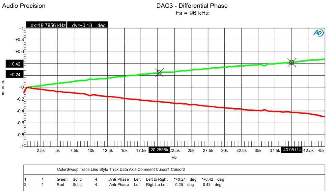
line
| Hz | Green Line (deg) | Red Line (deg) | | -------- | ---------------- | -------------- | | 20.2555k | +0.42 | - | | 40.0511k | +0.42 | - |DAC3 - Differential Phase.at27
Graph 6 - Differential Phase
This plot demonstrates the inter-channel phase accuracy of the DAC3. This is a highly expanded scale, spanning only +/- 1 degree at 45 kHz. From this plot, the inter-channel phase accuracy is calculated to be +/- 0.25 degrees at 20 kHz, and +/- 0.43 degrees at 40 kHz.
The phase accuracy of the DAC3 approaches the phase accuracy of the Audio Precision AP2722 test set. For this reason, the phase error in the AP must be subtracted from the measurement. The green trace assigns the left channel to channel 1 of the AP, and the right channel to channel 2 of the AP. The red trace reverses the inputs. The two traces must be averaged to remove the phase errors of the AP test set.
DAC3 converters are phase-accurate between boxes. Three DAC3 converters can be used as a group to form a phase-accurate 5.1 surround system. Four DAC3 converters can be combined to form a 7.1 system. The phase accuracy between any two channels will match the typical phase accuracy shown above.
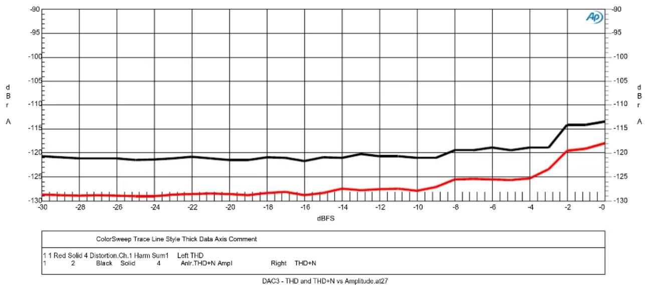
line
| dBFS | Black Line Value | Red Line Value | |------|------------------|----------------| | -30 | -120 | -130 | | -28 | -120 | -130 | | -26 | -120 | -130 | | -24 | -120 | -130 | | -22 | -120 | -130 | | -20 | -120 | -130 | | -18 | -120 | -130 | | -16 | -120 | -130 | | -14 | -120 | -125 | | -12 | -120 | -125 | | -10 | -120 | -125 | | -8 | -120 | -125 | | -6 | -120 | -125 | | -4 | -120 | -125 | | -2 | -115 | -120 | | 0 | -115 | -120 |Graph 7 - THD and THD+N vs. Amplitude (Balanced Outputs)
These plots demonstrate the very low harmonic distortion produced by the DAC3 with digital input signal levels ranging from -30 dBFS to 0 dBFS. These plots show that THD should never reach the threshold of hearing in most listening environments. This is proof that the DAC3 is virtually uncolored by any traces of harmonic distortion.
The black curve is a plot of THD+N, band limited to 22 kHz, and was acquired using the analog analyzer in the AP2722 test set. The red curve is a plot of THD (harmonic distortion only) and was acquired using the analog notch filter, A/D converter, and digital harmonic distortion analyzer in the AP2722 test set. This THD curve includes all harmonics falling below 32 kHz. The steps near -3 dBFS and -9 dBFS are due to the auto ranging of the AP2722 test set and are an indication that the THD performance of the DAC3 is very close to the measurement limits of the AP2722.
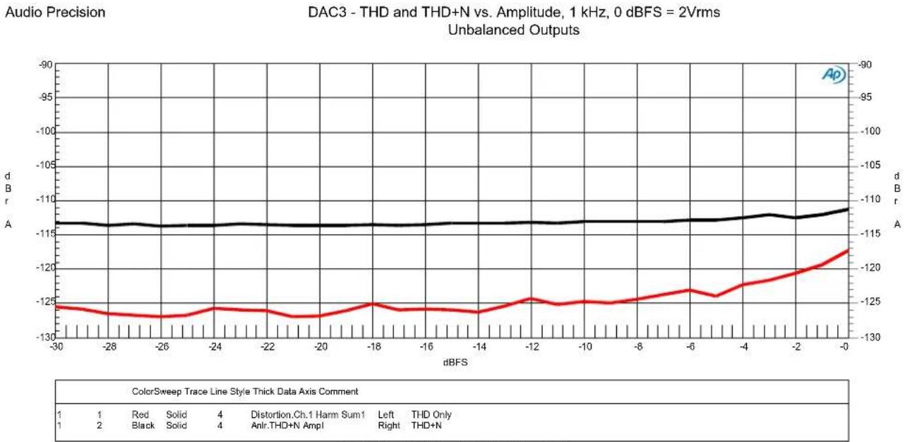
line
| dBFS | dB (Red Solid) | dB (Black Solid) | dB (Black Solid) | dB (Black Solid) | dB (Black Solid) | |------|----------------|------------------|------------------|------------------|------------------| | -30 | -125 | -125 | -125 | -125 | -125 | | -28 | -125 | -125 | -125 | -125 | -125 | | -26 | -125 | -125 | -125 | -125 | -125 | | -24 | -125 | -125 | -125 | -125 | -125 | | -22 | -125 | -125 | -125 | -125 | -125 | | -20 | -125 | -125 | -125 | -125 | -125 | | -18 | -125 | -125 | -125 | -125 | -125 | | -16 | -125 | -125 | -125 | -125 | -125 | | -14 | -125 | -125 | -125 | -125 | -125 | | -12 | -125 | -125 | -125 | -125 | -125 | | -10 | -125 | -125 | -125 | -125 | -125 | | -8 | -125 | -125 | -125 | -125 | -125 | | -6 | -125 | -125 | -125 | -125 | -125 | | -4 | -125 | -125 | -125 | -125 | -125 | | -2 | -120 | -120 | -120 | -120 | -120 | | 0 | -100 | 0 | 0 | 0 | 0 |DAC3 - THD and THD+N vs Amplitude Unbalanced.at27
Graph 8 - THD and THD+N vs. Amplitude (Unbalanced Outputs)
This plot shows the THD and THD+N performance of the unbalanced outputs.
Note that the THD performance of the unbalanced outputs approaches that of the balanced outputs. The THD+N levels are slightly higher on the unbalanced outputs. This is due to the relatively low (2 Vrms) signal levels used on unbalanced interfaces. This noise difference highlights one advantage of professional-level balanced interconnects.
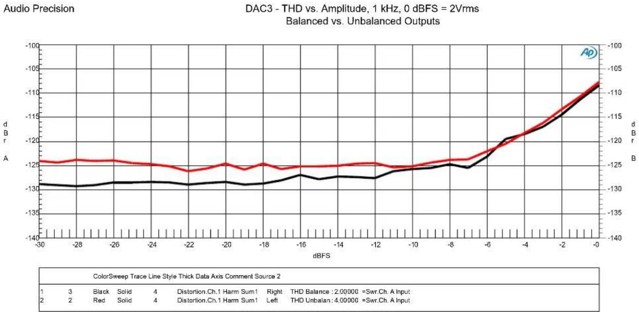
line
| dBFS | dB (Balanced) | dB (Unbalanced) | |------|---------------|----------------| | -30 | -125 | -130 | | -28 | -125 | -130 | | -26 | -125 | -130 | | -24 | -125 | -130 | | -22 | -125 | -130 | | -20 | -125 | -130 | | -18 | -125 | -130 | | -16 | -125 | -130 | | -14 | -125 | -130 | | -12 | -125 | -130 | | -10 | -125 | -130 | | -8 | -125 | -130 | | -6 | -125 | -125 | | -4 | -120 | -120 | | -2 | -115 | -115 | | 0 | -105 | -105 |DAC3 - THD vs Amplitude Balanced vs Unbalanced.at27
Graph 9 - THD vs. Amplitude - Balanced vs. Unbalanced Outputs
This plot demonstrates that the balanced and unbalanced analog outputs on the DAC3 have very similar THD performance. The unbalanced outputs (red curve) closely match the performance of the balanced outputs (black curve) at high signal levels. The separation between the curves at signal levels below -10 dBFS is due to the improved SNR provided by the balanced interfaces. At 0 dBFS, the balanced interfaces were calibrated to +24 dBu (12.28 Vrms) while the unbalanced interfaces were calibrated to +8.24 dBu (2 Vrms). The higher signal levels used with the balanced interfaces make it easier to achieve high signal to noise ratios. This is just one reason why Benchmark recommends balanced interconnects.
The DAC3 includes differential amplifiers that remove common-mode THD from the balanced outputs of the SABRE-PRO converters. These differential amplifiers give the unbalanced outputs the ability to approach the THD performance of the balanced outputs. Please note that the differential amplifiers also eliminate common-mode distortion on the balanced outputs.
Top-quality D/A conversion chips (such as the ES9028PRO) are equipped with balanced outputs. These balanced outputs allow a significant reduction of THD if they are followed by precision differential amplifiers. Conversion chips tend to produce significant common-mode distortion products that should be removed by a differential amplifier. The DAC3 includes precision differential amplifiers following the outputs of the ES9028PRO. Many competing products omit these differential amplifiers. The omission of the differential amplifiers would make the THD much higher on the unbalanced outputs. The differential amplifiers also improve the system performance when the balanced outputs are driving balanced inputs that are not precisely trimmed.
The THD measurements shown above confirm the effectiveness of the differential amplifiers in the DAC3. Additional confirmation can be obtained by measuring the THD of either side of the balanced outputs relative to ground.
Audio Precision
DAC3 - THD+N VS FREQ AT 0 dBFS, 24 dBu (w/80 kHz LPF unweighted)
Balanced Outputs
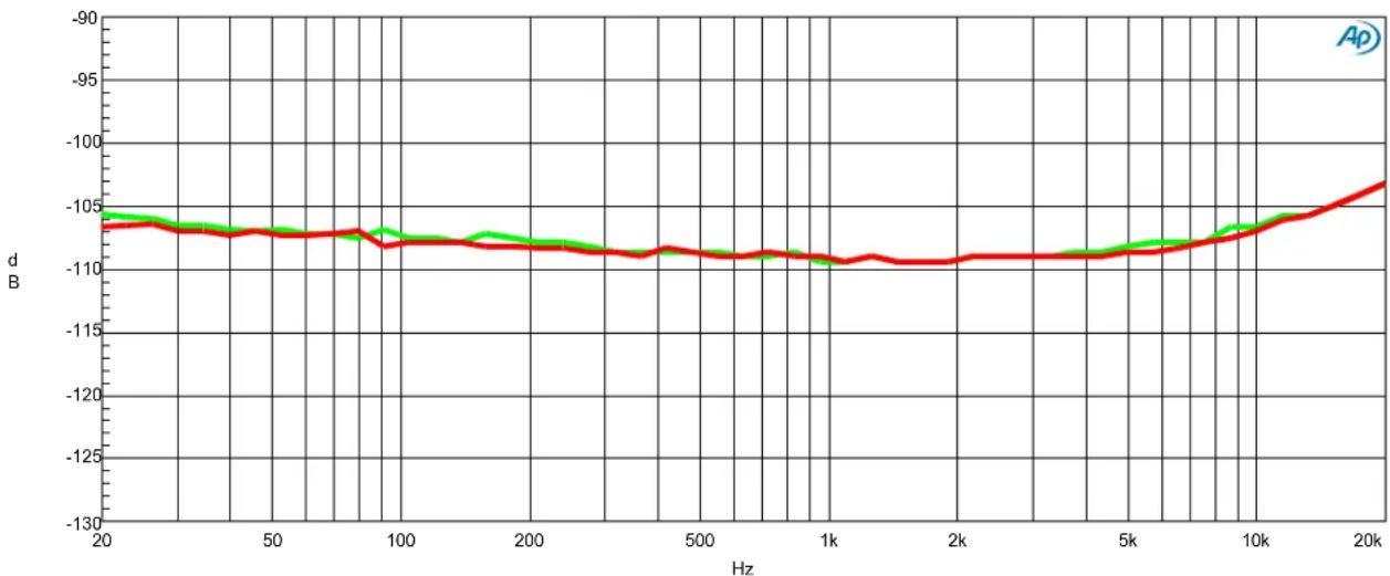
line
| Hz | d B (Red Line) | d B (Green Line) | |------|----------------|------------------| | 20 | -106.0 | -105.5 | | 50 | -107.0 | -106.5 | | 100 | -108.0 | -107.5 | | 200 | -109.0 | -108.5 | | 500 | -110.0 | -109.5 | | 1k | -111.0 | -110.5 | | 2k | -110.5 | -110.0 | | 5k | -110.0 | -109.5 | | 10k | -109.5 | -109.0 | | 20k | -108.5 | -108.0 |ColorSweep Trace Line Style Thick Data Axis Comment
1 1 Green Solid 4 Anlr.THD+N Ratio Left Left Channel
1 2 Red Solid 4 Anlr.THD+N Ratio Left Right Channel
DAC3 - THD+N vs FREQUENCY 80kHz.at27
Graph 10 - THD+N vs. Frequency 80 kHz
The analog output stages on the DAC3 have high slew rates and are capable of maintaining low THD levels at high frequencies even when driven to 0 dBFS. Note that the THD+N remains very low at 20 kHz, even when operating at maximum output levels.
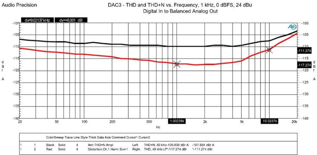
line
| Frequency (Hz) | THD+N (dB) | THD+N (dB) | | -------------- | ---------- | ---------- | | 1.00238 | -117.274 | -111.274 | | 10.0237 | -117.274 | -111.274 |DAC3 - THD and THD+N vs Frequency Digital to Analog.at27
Graph 11 - THD and THD+N vs. Frequency
These plots demonstrate that the harmonic distortion of the DAC3 is lower than the THD+N numbers would suggest. This black curve is a plot of THD+N. The red curve is a plot of THD only. Below about 10 kHz, the THD is so low that the THD+N measurement is dominated by noise.
Audio Precision
DAC3 - THD+N vs Sample Rate, 1 kHz at 0 dBFS (w/20 kHz LPF unweighted)
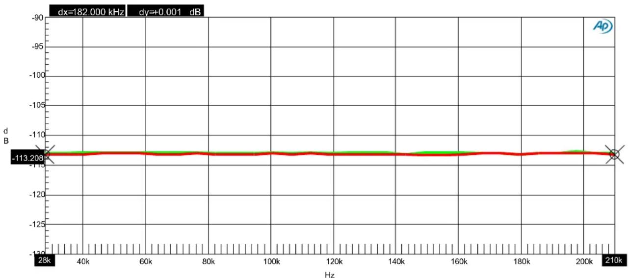
line
| Hz | d B | |-------|---------| | 28k | -113.208| | 40k | -113.208| | 60k | -113.208| | 80k | -113.208| | 100k | -113.208| | 120k | -113.208| | 140k | -113.208| | 160k | -113.208| | 180k | -113.208| | 200k | -113.208| | 210k | -113.208|| ColorSweep Trace Line Style Thick Data Axis Comment Cursor1 Cursor2 | ||||||||
| 1 | 1 | Green | Solid | 4 | AnIr.THD+N Ratio | Left | Left Channel | -113.043 dB -113.041 dB |
| 1 | 2 | Red | Solid | 4 | AnIr.THD+N Ratio | Left | Right Channel | *-113.209 dB *-113.208 dB |
DAC3 - THD+N vs Sample Rate.at27
Graph 12 - THD+N versus Sample Rate
The THD+N performance of the DAC3 is identical at all Sample Rates.
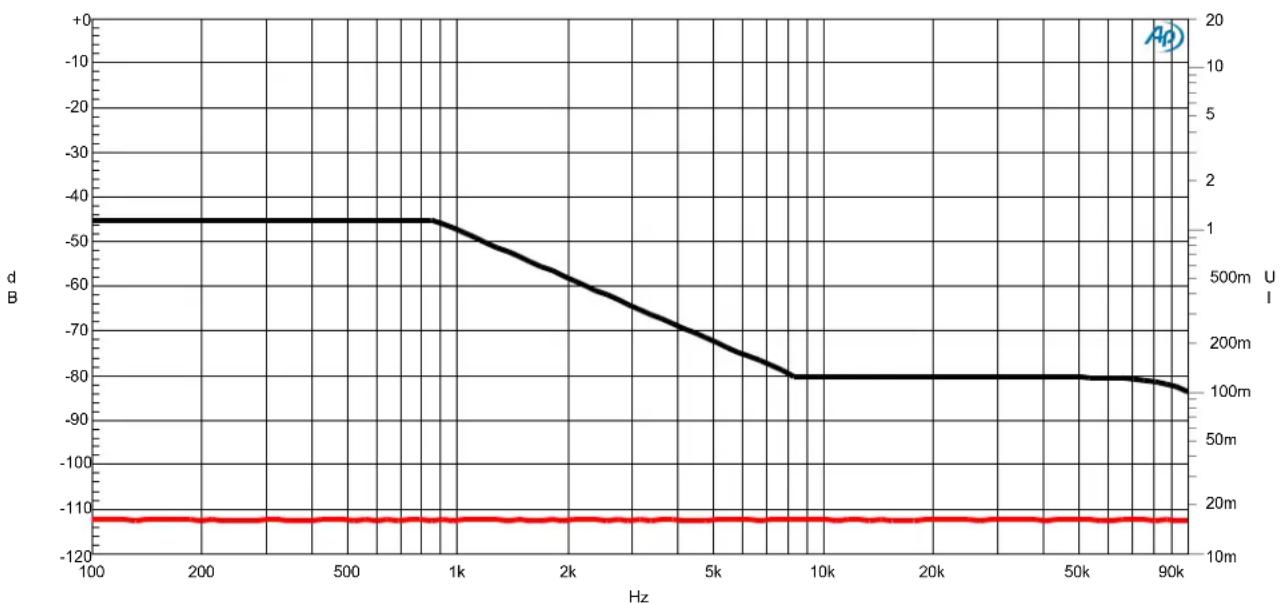
line
| Hz | dB | U/I | | ---- | ----- | ----- | | 100 | -45 | 1 | | 200 | -45 | 1 | | 500 | -45 | 1 | | 1k | -45 | 1 | | 2k | -60 | 500m | | 5k | -75 | 200m | | 10k | -80 | 100m | | 20k | -80 | 100m | | 50k | -80 | 100m | | 90k | -85 | 100m || ColorSweep Trace Line Style Thick Data Axis Comment | ||||||
| 1 | 1 Red Solid 4 | Anlr.THD+N Ratio | Left | |||
| 1 | 2 | Black | Solid | 4 | Dio.Interface Jitter | Right |
DAC3 - JITTER TOLERANCE.at27
Graph 13 - Jitter Tolerance
The Audio Engineering Society (AES) has created a jitter tolerance template for testing digital audio devices. The black curve shows the AES jitter tolerance template (see right-hand vertical axis). Induced jitter approaches 5 UI at 200 Hz, and is reduced to 0.125 UI above 8 kHz. The red trace shows the THD+N of the DAC3 (left-hand vertical axis) while being driven with the jitter shown on the black curve. Over the entire range of the AES jitter tolerance test, the THD+N performance of the DAC3 is unchanged. The DAC3 easily passes the AES jitter tolerance test, and it does so without any performance degradation.
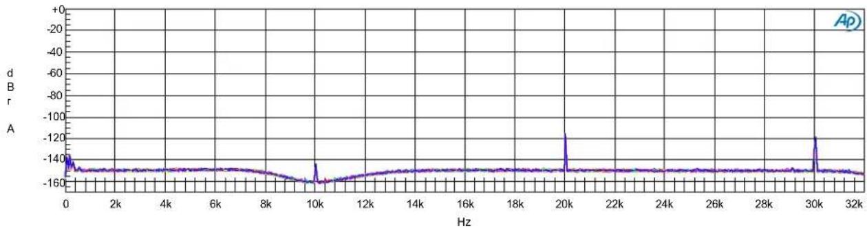
line
| Hz | d B r A | | ---- | ------- | | 0 | -140 | | 2k | -145 | | 4k | -148 | | 6k | -147 | | 8k | -149 | | 10k | -155 | | 12k | -152 | | 14k | -150 | | 16k | -150 | | 18k | -150 | | 20k | -120 | | 22k | -150 | | 24k | -150 | | 26k | -150 | | 28k | -150 | | 30k | -120 | | 32k | -150 || ColorSweep Trace Line Style Thick Data Axis Comm ent Source 2 | |||||||
| 1 | 2 | Blue | Solid | 1 | Ft.Ch.1 Ampl | Left | : 100.000 Hz=Dio.Jitter Freq |
| 2 | 2 | Cyan | Solid | 1 | Ft.Ch.1 Ampl | Left | : 125.893 Hz=Dio.Jitter Freq |
| 3 | 2 | Green | Solid | 1 | Ft.Ch.1 Ampl | Left | : 158.489 Hz=Dio.Jitter Freq |
| 4 | 2 | Yellow | Solid | 1 | Ft.Ch.1 Ampl | Left | : 199.526 Hz=Dio.Jitter Freq |
| 5 | 2 | Red | Solid | 1 | Ft.Ch.1 Ampl | Left | : 251.189 Hz=Dio.Jitter Freq |
| 6 | 2 | Magenta | Solid | 1 | Ft.Ch.1 Ampl | Left | : 316.228 Hz=Dio.Jitter Freq |
| 7 | 2 | Blue | Solid | 1 | Ft.Ch.1 Ampl | Left | : 398.107 Hz=Dio.Jitter Freq |
| 8 | 2 | Cyan | Solid | 1 | Ft.Ch.1 Ampl | Left | : 501.187 Hz=Dio.Jitter Freq |
| 9 | 2 | Green | Solid | 1 | Ft.Ch.1 Ampl | Left | : 630.957 Hz=Dio.Jitter Freq |
| 10 | 2 | Yellow | Solid | 1 | Ft.Ch.1 Ampl | Left | : 794.328 Hz=Dio.Jitter Freq |
| 11 | 2 | Red | Solid | 1 | Ft.Ch.1 Ampl | Left | : 1.00000 kHz=Dio.Jitter Freq |
| 12 | 2 | Magenta | Solid | 1 | Ft.Ch.1 Ampl | Left | : 1.25893 kHz=Dio.Jitter Freq |
| 13 | 2 | Blue | Solid | 1 | Ft.Ch.1 Ampl | Left | : 1.58489 kHz=Dio.Jitter Freq |
| 14 | 2 | Cyan | Solid | 1 | Ft.Ch.1 Ampl | Left | : 1.99526 kHz=Dio.Jitter Freq |
| 15 | 2 | Green | Solid | 1 | Ft.Ch.1 Ampl | Left | : 2.51189 kHz=Dio.Jitter Freq |
| 16 | 2 | Yellow | Solid | 1 | Ft.Ch.1 Ampl | Left | : 3.16228 kHz=Dio.Jitter Freq |
| 17 | 2 | Red | Solid | 1 | Ft.Ch.1 Ampl | Left | : 3.98107 kHz=Dio.Jitter Freq |
| 18 | 2 | Magenta | Solid | 1 | Ft.Ch.1 Ampl | Left | : 5.01187 kHz=Dio.Jitter Freq |
| 19 | 2 | Blue | Solid | 1 | Ft.Ch.1 Ampl | Left | : 6.30957 kHz=Dio.Jitter Freq |
| 20 | 2 | Cyan | Solid | 1 | Ft.Ch.1 Ampl | Left | : 7.94328 kHz=Dio.Jitter Freq |
| 21 | 2 | Green | Solid | 1 | Ft.Ch.1 Ampl | Left | : 10.0000 kHz=Dio.Jitter Freq |
| 22 | 2 | Yellow | Solid | 1 | Ft.Ch.1 Ampl | Left | : 12.5893 kHz=Dio.Jitter Freq |
| 23 | 2 | Red | Solid | 1 | Ft.Ch.1 Ampl | Left | : 15.8489 kHz=Dio.Jitter Freq |
| 24 | 2 | Magenta | Solid | 1 | Ft.Ch.1 Ampl | Left | : 19.9526 kHz=Dio.Jitter Freq |
| 25 | 2 | Blue | Solid | 1 | Ft.Ch.1 Ampl | Left | : 25.1189 kHz=Dio.Jitter Freq |
| 26 | 2 | Cyan | Solid | 1 | Ft.Ch.1 Ampl | Left | : 31.6228 kHz=Dio.Jitter Freq |
| 27 | 2 | Green | Solid | 1 | Ft.Ch.1 Ampl | Left | : 39.8107 kHz=Dio.Jitter Freq |
| 28 | 2 | Yellow | Solid | 1 | Ft.Ch.1 Ampl | Left | : 50.1187 kHz=Dio.Jitter Freq |
| 29 | 2 | Red | Solid | 1 | Ft.Ch.1 Ampl | Left | : 63.0957 kHz=Dio.Jitter Freq |
| 30 | 2 | Magenta | Solid | 1 | Ft.Ch.1 Ampl | Left | : 79.4328 kHz=Dio.Jitter Freq |
| 31 | 2 | Blue | Solid | 1 | Ft.Ch.1 Ampl | Left | : 100.000 kHz=Dio.Jitter Freq |
DAC3 - JITTER TOLERANCE FFT.at27
Graph 14 - Jitter Tolerance FFT
This figure shows a series of FFTs that were acquired while running the AES jitter tolerance test. This is the ultimate jitter-immunity test.
Note that none of the 31 FFTs show any signs of jitter-induced sidebands. Note that the plots are identical to the plots shown in Graph 3.
The DAC3 shows no change in performance when the AES jitter tolerance test is applied to the digital inputs. No jitter-induced sidebands are visible anywhere in this measurement.
Please note that the 10 kHz fundamental needed to be notched out in order to make this very high-resolution measurement. If the fundamental was not notched out, the spurious tones, produced by the A/D converter in the AP2722 test set, would have obscured the virtually-perfect results.
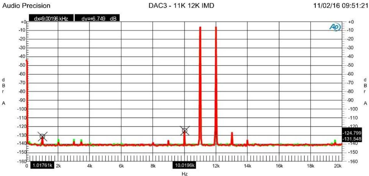
line
| Frequency (Hz) | Amplitude (dB) | | -------------- | -------------- | | 1.01761 | -130 | | 10.0196 | -124.799 | | 12 | -131.548 || ColorSweep Trace Line Style Thick Data Axis Comment Cursor1 Cursor2 | ||||||||
| 1 | 1 | Green | Solid | 4 | Fft.Ch.1 Ampl | Left | Left Channel | -131.652 dBr A -125.861 dBr A |
| 1 | 2 | Red | Solid | 4 | Fft.Ch.2 Ampl | Right | Right Channel | *-131.548 dBr *-124.799 dBr |
DAC3 - IMD 11K 12K.at27
Graph 15 - IMD 11k 12K
This plot demonstrates that the DAC3 has very low IMD distortion. The 1 kHz difference frequency measures -131 dB, and the 10 kHz and 13 kHz products measure about -125 dB. The actual IMD may be better. The results shown are partially limited by the performance of the AP2722 test set.
All IMD distortion products should be well below audible levels.
Specifications
| Audio Performance | |
| Fs = 44.1 to 96 kHz, 20 to 20 kHz BW, 1 kHz test tone, 0 dBFS = +24 dBu (unless noted) | |
| SNR - A-Weighted, 0 dBFS = +24 dBu | 124.5 dB, 128 dB relative to dig. clip |
| SNR - Unweighted, 0 dBFS = +24 dBu | 122.5 dB, 126 dB relative to dig. clip |
| Dynamic Range - A-Weighted, 0 dBFS = +24 dBu | 124.5 dB, 128 dB relative to dig. clip |
| Dynamic Range - Unweighted, 0 dBFS = +24 dBu | 122.5 dB, 126 dB relative to dig. clip |
| THD+N, 1 kHz at 0 dBFS | -113 dBFS, -113 dB, 0.00022% |
| THD+N, 1 kHz at -1 dBFS | -114 dBFS, -113 dB, 0.00022% |
| THD+N, 1 kHz at -3 dBFS | -119 dBFS, -116 dB, 0.00016% |
| THD+N, 20 to 20 kHz sweep at -3 dBFS | -113 dBFS, -110 dB, 0.00032% |
| Frequency Response at Fs=192 kHz | +0 dB, -0.015 dB (20 to 20 kHz)-0.015 dB at 10 Hz-0.005 dB at 20 kHz-0.031 dB at 40 kHz-0.15 dB at 80 kHz |
| Frequency Response at Fs=48 kHz | +0 dB, -0.015 dB (20 to 20 kHz)-0.015 dB at 10 Hz-0.005 dB at 20 kHz |
| Crosstalk | -116 dB at 20 kHz-130 dB at 1 kHz-137 dB at 20 Hz |
| Maximum Amplitude of Jitter Induced Sidebands (10 kHz 0 dBFS test tone, 12.75 UI sinusoidal jitter at 1 kHz) | <-144 dB |
| Maximum Amplitude of Spurious Tones with 0 dBFS test signal | <-138 dB |
| Maximum Amplitude of Idle Tones | <-147 dB |
| Maximum Amplitude of AC line related Hum & Noise | <-133 dB |
| Inter-channel Differential Phase (Stereo Pair - any sample rate) | +/- 0.25 degrees at 20 kHz |
| Inter-channel Differential Phase (Between DAC3 Units Fs<110 kHz) Any sample rate. | +/- 0.25 degrees at 20 kHz |
| Maximum Lock Time after Fs change | 6 ms |
| Soft Mute Ramp Up/Down Time | 9.6 ms |
| Mute on Receive Error | Yes |
| Mute on Lock Error | Yes |
| Mute on Idle Channel | No |
| 50/15 us De-Emphasis Enable | Automatic in Consumer Mode |
| De-Emphasis Method | Digital IIR |
| De-Emphasis Supported at | Fs = 32, 44.1, 48 kHz |
| Group Delay (Latency) | |
| Delay – Digital Input to Analog Output (function of sample rate) | 1.36 ms at 44.1 kHz |
| 1.27 ms at 48 kHz | |
| 0.90 ms at 88.2 kHz | |
| 0.82 ms at 96 kHz | |
| 0.51 ms at 176.4 kHz | |
| 0.47 ms at 192 kHz | |
| Digital Audio Inputs | |
| Number of Digital Inputs (switch selected) | 5 (1 USB, 2 Optical, 2 Coaxial) |
| Number of Channels | 2 |
| Input Sample Frequency Range | 28 to 210 kHz (Coaxial Inputs) |
| 28 to 96 kHz (Optical Inputs) | |
| 44.1, 48, 88.2, 96, 176.4, 192 kHz (USB Input) | |
| Maximum Input Word Length | 24 bits |
| Digital Input Impedance | 75 Ohms (Coaxial Inputs) |
| DC Blocking Capacitors on Digital Inputs | Yes (Coaxial Inputs) |
| Transient and Over-Voltage Protection on Digital Inputs | Yes (Coaxial Inputs) |
| Minimum Digital Input Level | 250 mVpp (Coaxial Inputs) |
| Jitter Tolerance | |
| (With no Measurable Change in Performance) | >12.75 UI sine, 100 Hz to 3 kHz |
| >1.5 UI sine at 20 kHz | |
| >1.5 UI sine at 40 kHz | |
| >1.5 UI sine at 80 kHz | |
| >1.5 UI sine at 90 kHz | |
| >0.25 UI sine above 160 kHz | |
| Jitter Attenuation Method | Benchmark UltraLock3^TM - all inputs |
| Balanced Analog Outputs | |
| Number of Balanced Analog Outputs | 2 |
| Output Connector | Gold-Pin NeutrikTM male XLR |
| Output Impedance | 60 Ohms (Attenuator off)425 Ohms (Attenuator = 10 dB)135 Ohms (Attenuator = 20 dB) |
| Analog Output Clip Point | +29 dBu |
| Factory Calibration (with 0 dBFS digital input) | +24 dBu (Attenuator = 0 dB) |
| Maximum Amplitude of Intersample Peaks | +27.5 dBu (Attenuator = 0 dB)+17.5 dBu (Attenuator = 10 dB)+7.5 dBu (Attenuator = 20 dB) |
| Output Level Variation with Sample Rate | < +/- 0.006 dB |
| Unbalanced Analog Outputs | |
| Number of Unbalanced Analog Outputs | 2 |
| Output Connector | RCA |
| Output Impedance | 30 Ohms |
| Analog Output Clip Point | +13.5 dBu (3.7 Vrms) |
| Factory Calibration (with 0 dBFS digital input) | +8.2 dBu (2 Vrms) |
| Maximum Amplitude of Intersample Peaks | +11.7 dBu (3 Vrms) |
| Output Level Variation with Sample Rate | < +/- 0.006 dB |
| Status Display | |
| Indicators - Type and Location | 12 LEDs on Front Panel |
| Selection/Status Indication | 1 – Control Lock5 – Input2 – Word length4 – Sample Rate |
| AC Power Requirements | |
| Nominal Operating Range | 100 - 240 VAC, 50 - 60 Hz |
| Min/Max Operating range | 88 - 264 VAC, 47 - 63 Hz |
| Power | < 0.5 Watts Standby12 Watts Typical Program15 Watts Maximum |
| Fuses (2 required) | 5x20 mm, 0.5 A 250 V Slo-Blo® Type |
| Dimensions | |
| Form Factor | 12 Rack Wide, 1 RU High |
| Depth behind front panel | 8.5" (216 mm) |
| Overall depth including connectors | 9.33" (237 mm) |
| Width | 9.5" (249 mm) |
| Height | 1.725" (44.5 mm) |
| Weight | |
| DAC3 B only | 3 lb. |
| DAC3 B with accessories and manual | 4 lb. |
| Shipping weight | 7 lb. |
Regulatory Compliance
FCC and RoHS Compliance Statements
FCC Notice (U.S. Only)
NOTICE: This equipment has been tested and found to comply with the limits for a Class B digital device, pursuant to Part 15 of the FCC Rules. These limits are designed to provide reasonable protection against harmful interference in a residential installation. This equipment generates, uses, and can radiate radio frequency energy and, if not installed and used in accordance with the instructions, may cause harmful interference to radio communications. However, there is no guarantee that interference will not occur in a particular installation. If this equipment does cause harmful interference to radio or television reception, which can be determined by turning the equipment off and on, the user is encouraged to try to correct the interference by one or more of the following measures:
- Reorient or relocate receiving antenna.
- Increase the separation between the equipment and receiver.
- Connect the equipment into an outlet on a circuit different from that to which the receiver is connected.
- Consult the dealer or an experienced radio/TV technician for help.
This device complies with Part 15 of the FCC rules. Operation is subject to the following two conditions:
- This device may not cause harmful interference.
- This device must accept any interference received including interference that may cause undesired operation.
Instructions to Users: This equipment complies with the requirements of FCC (Federal Communication Commission) equipment provided that following conditions are met:
• RCA Digital Connections: Shielded 75-Ohm coaxial cable must be used.
NOTICE: Changes or modifications not expressly approved by the party responsible for compliance could void the user's authority to operate the equipment.
RoHS Compliant Information
This statement clarifies Benchmark Media Systems, Inc. product compliance with the EU's (European Union) directive 2002/95/EC, or, RoHS (Restrictions of Hazardous Substances).
As of July 01, 2006, All Benchmark Media Systems, Inc. products placed on the European Union market are compliant (containing quantity limit weight less than or equal to 0.1% (1000 ppm) of any homogeneous Lead (Pb), Mercury (Hg), Hexavalent Chromium (Cr VI), and flame retardant Polybrominated Biphenyls (PBB) or Polybrominated Diphenyl Ethers (PBDE)).
Certificate of Conformity
Diversified T.E.S.T. Technologies, Inc. has tested the product to the current appropriate standards and finds that the product is in compliance with those requirements.
EMC Directive:
Generic Emissions Standard:
Product Specific Emissions:
Generic Immunity Standard:
Immunity:
2004/108/EC
EN 61000-6-3:2007/A1:2011
EN 55011 Class A
EN 61000-6-1:2007
EN 61000-4-2
EN 61000-4-3
EN 61000-4-6
Electrostatic Discharge
Radiated Susceptibility
Conducted Susceptibility
Manufacturer's Name:
Manufacturer's Address:
Product:
Model Number:
This Certificate of Compliance issued September 21, 2012 is valid for the test sample of the product specified above and that it conforms to the Directive(s) and Standard(s).
Signature:

Annette Frierson
Vice President
Diversified T.E.S.T. Technologies, Inc.
4675 Burr Drive
Liverpool, NY 13088
Phone: 315-457-0245
Fax: 315-457-0428

Warranty Information
Benchmark 1-Year Warranty
The Benchmark 1-Year Warranty
Benchmark Media Systems, Inc. warrants its products to be free from defects in material and workmanship under normal use and service for a period of one year from the date of delivery.
This warranty extends only to the original purchaser. This warranty does not apply to fuses, lamps, batteries, or any products or parts that have been subjected to misuse, neglect, accident, modification, or abnormal operating conditions.
In the event of failure of a product under this warranty, Benchmark Media Systems, Inc. will repair, at no charge, the product returned to its factory. Benchmark Media Systems, Inc. may, at its option, replace the product in lieu of repair. If the failure has been caused by misuse, neglect, accident, or, abnormal operating conditions, repairs will be billed at the normal shop rate. In such cases, an estimate will be submitted before work is started, if requested by the customer.
Attempts to deliberately deface, mutilate, or remove the product's label will render this warranty void. Benchmark will not honor warranties for any products disingenuously purchased on the US or Canadian markets for export.
The foregoing warranty is in lieu of all other warranties, expressed or implied, including but not limited to any implied warranty of merchantability, fitness or adequacy for any particular purpose or use. Benchmark Media Systems, Inc. shall not be liable for any special, incidental, or consequential damages, and reserves the right to change this information without notice. This limited warranty gives the consumer-owner specific legal rights, and there may also be other rights that vary from state to state.
The Benchmark Extended 5-Year Warranty \*
Benchmark Media Systems, Inc. optionally extends the standard 1-year warranty to a period of five years from the date of delivery.
*For the extended warranty to become effective, the original purchaser must register the product at the time of purchase either by way of the enclosed registration card or through the product registration section of the Benchmark Media Systems, Inc. website. This optional warranty applies only to products purchased within the US and Canada and is extended only to the original purchaser.
Attempts to deliberately deface, mutilate, or remove the product's label will render this warranty void. Benchmark will not honor warranties for any products disingenuously purchased on the US or Canadian markets for export. The terms of the extended warranty are subject to change without notice. For products purchased outside the US and Canada, please refer to the Extended Two 2-Year International Warranty.
The Benchmark Extended 2-Year International Warranty \*\*
Benchmark Media Systems, Inc. optionally extends the standard 1-year warranty to a period of two years from the date of delivery.
**For the extended warranty to become effective, the original purchaser must register the product at the time of purchase either by way of the enclosed registration card or through the product registration section of the Benchmark Media Systems, Inc. website. This optional warranty applies only to products purchased outside the US and Canada and is extended only to the original purchaser.
Attempts to deliberately deface, mutilate, or remove the product's label will render this warranty void. Benchmark will not honor warranties for any products disingenuously purchased on the US or Canadian markets for export. The terms of the extended warranty are subject to change without notice. For products purchased in within the US and Canada, please refer to the Extended Five 5-Year Warranty.
Notes on Warranty Repairs
An RMA (return merchandise authorization) number, issued by our Customer Service Department, is required when sending products for repair.
They must be shipped to Benchmark Media Systems prepaid and preferably in their original shipping carton with the RMA number clearly visible on the exterior of the packaging. A letter should be included giving full details of the difficulty.
Revision A - 10/22/2018
Copyright © 2007, 2008, 2009, 2012, 2013, 2014, 2015, 2016, 2017, 2018
Benchmark Media Systems, Inc.
All rights reserved.
Benchmark Media Systems, Inc.
Benchmark Media Systems, Inc.
203 East Hampton Place, STE 2
Syracuse, NY 13206
USA
PHONE: +1-315-437-6300
FAX: +1-315-437-8119
benchmarkmedia.com

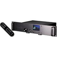
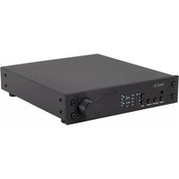


- Benchmark DAC3 B Instruction Manual
- Safety Information
- Fuses
- AC Input Voltage Range
- Power Cord
- Modifications
- Repairs
- Contents
- Safety Information 2
- Features 4
- Introduction 5
- Front Panel 8
- Rear Panel 8
- Quick Start Guide 9
- Operational Details
- Rear Panel
- Internal Settings
- Rack Mounting 27
- DAC1, DAC2 and DAC3 Family History 28
- Benchmark Technologies 30
- USB Driver Installation 37
- Performance Graphs 42
- Specifications 57
- Regulatory Compliance 61
- Warranty Information 63
- Features
- Introduction
- Applications
- DAC3 vs. DAC2
- DAC3 vs. DAC1
- DAC3 Technologies
- 4:1 Parallel Conversion Structure
- Harmonic Compensation
- High-Headroom Digital and Analog Processing
- No Clipping of Intersample Overs
- Low-Noise Power Supplies
- Low Magnetic Emissions
- UltraLock3™ Clock System
- Dual-Mode USB Input
- Asynchronous USB Audio 2.0
- Native Asynchronous USB 1.1
- Low-Impedance Passive Attenuators
- Native DSD Conversion
- Digital Pass-Through
- Bi-directional 12V Trigger
- Auto-On Function
- Front Panel
- Quick Start Guide
- Audio Inputs
- Front Panel Display
- Input Indicators
- Input Error Codes
- Tip: Common causes of input errors:
- Digital Format Indicators
- Word Length Indicators
- Format indicators
- Enabling AUTO-ON
- Disabling AUTO-ON
- CONTROL-LOCK Function
- Trigger Output (DAC3 is Master)
- Trigger Input - (DAC3 is Slave)
- Typical Trigger Applications
- Bi-Directional Trigger Applications
- Trigger Specifications
- HPA4, LA4 Compatibility
- USB MODE Selection
- High-Current Outputs
- Driving Power Amplifiers
- Firmware Version Identification
- Inputs
- Digital Inputs - Overview
- Computer Input - USB
- Optical Digital Inputs - D1 and D2
- Coaxial Digital Inputs - D3 and D4
- 12V TRIGGER I/O
- Outputs
- Balanced XLR Analog Line Outputs
- Industry-Standard XLR Wiring
- Unbalanced RCA Analog Outputs
- AC Power-Entry and Fuse Module
- Input Voltage Range
- Jumper-Configured Options
- Removing Top Cover
- XLR Output Pads
- XLR Output Pad Jumpers
- Digital PASS-THROUGH Function
- Digital PASS-THROUGH Jumpers
- Rack Mounting
- Benchmark Rack-Mount Coupler
- Benchmark Rack Mount Tray
- Benchmark 1/2-Wide Blank Plate
- DAC1, DAC2 and DAC3 Family History
- DAC1 Series
- DAC1
- DAC1 USB
- DAC1 PRE
- DAC1 HDR
- DAC2 Series
- DAC2 HGC
- DAC2 L
- DAC2 D
- DAC2 DX
- DAC3 Series
- Benchmark Technologies
- High Headroom DSP
- 32-bit SABRE-PRO D/A System
- Diagnostic Displays
- Bi-Directional 12 Volt Trigger
- Distributed Power Regulation
- Differential Amplifiers
- Jitter-Immune UltraLock3™
- The Importance of Eliminating Jitter
- Put UltraLock™ converters to the test:
- Is it possible to eliminate all of the effects of jitter in an entire digital audio system?
- What UltraLock™ converters cannot do:
- Multi-Mode Asynchronous USB Audio
- Asynchronous USB
- USB Driver Installation
- Windows Operating Systems
- Performance Graphs
- Graph 1 - FFT Idle Channel Noise
- Graph 2 - Low Frequency FFT - AC Line-Related Hum
- Graph 3 - FFT 10 kHz
- Graph 4 - FFT 1 kHz
- Graph 5 - Frequency Response
- Graph 6 - Differential Phase
- Graph 7 - THD and THD+N vs. Amplitude (Balanced Outputs)
- Graph 8 - THD and THD+N vs. Amplitude (Unbalanced Outputs)
- Graph 9 - THD vs. Amplitude - Balanced vs. Unbalanced Outputs
- Graph 10 - THD+N vs. Frequency 80 kHz
- Graph 11 - THD and THD+N vs. Frequency
- Graph 12 - THD+N versus Sample Rate
- Graph 13 - Jitter Tolerance
- Graph 14 - Jitter Tolerance FFT
- Graph 15 - IMD 11k 12K
- Specifications
- Regulatory Compliance
- FCC and RoHS Compliance Statements
- FCC Notice (U.S. Only)
- RoHS Compliant Information
- Certificate of Conformity
- EMC Directive:
- 2004/108/EC
- Manufacturer's Name:
- Product:
- Signature:
- Warranty Information
- Benchmark 1-Year Warranty
- The Benchmark 1-Year Warranty
- The Benchmark Extended 5-Year Warranty \*
- The Benchmark Extended 2-Year International Warranty \*\*
- Notes on Warranty Repairs
Brand : Benchmark
Model : DAC3 B
Category : Headphones