
AD-S402T - Loudspeaker QSC - Free user manual and instructions
Find the device manual for free AD-S402T QSC in PDF.


| Product Type | Surface Mount Loudspeaker |
| Brand | QSC |
| Model | AD-S402T |
| Driver Configuration | 4" Coaxial Two-Way |
| Frequency Response | 75 Hz – 20 kHz (-10 dB) |
| Power Handling (RMS) | 60 W (Continuous), 120 W (Peak) |
| Impedance | 8 Ohms (Bypass Mode) |
| Transformer Taps (70V/100V) | 60W, 30W, 15W, 7.5W |
| Sensitivity | 87 dB SPL (1W/1m) |
| Dimensions (H x W x D) | 6.73" x 11.26" x 6.73" (171 x 286 x 171 mm) |
| Weight | 8.2 lbs (3.7 kg) |
| Construction Material | High-Impact Polystyrene Enclosure, Powder-Coated Aluminum Grille |
| Color | Black or White |
| Mounting | Included U-Bracket for Wall or Ceiling Mount; Optional Pendant Kit |
| Ingress Protection | IP54 (Splash and Dust Resistant) |
| Operating Temperature | -4°F to 122°F (-20°C to 50°C) |
| Applications | Foreground/Background Music, Paging, Retail, Hospitality, Conference Rooms |
| Included Accessories | U-Bracket, Euroblock Connector, Safety Cable, Mounting Hardware |
| Recommended Use | Indoor or Outdoor Covered Areas |
| Safety Certifications | UL 1480, CE, EN 54-24 (for voice alarm) |
Frequently Asked Questions - AD-S402T QSC
User questions about AD-S402T QSC
0 question about this device. Answer the ones you know or ask your own.
Ask a new question about this device
Download the instructions for your Loudspeaker in PDF format for free! Find your manual AD-S402T - QSC and take your electronic device back in hand. On this page are published all the documents necessary for the use of your device. AD-S402T by QSC.
USER MANUAL AD-S402T QSC
NOTE: The AD-S402T is UL listed (1480A) for indoor use only
Installation
AD-S402T passive column loudspeaker systems require amplified audio signals. A pass-through on each loudspeaker permits connection to multiple loudspeakers.
The pluggable “Eurostyle” connectors allow the installer to pre-wire the audio system on site before the loudspeakers are installed.
AD-S402T Weather Cover

The loudspeaker comes with a weather cover for the input cup to protect the input connections and switches from precipitation and other weather hazards (Figure 1). Use the weather cover for all non-UL outdoor installations or any applications where the loudspeaker may be exposed to moisture. To ensure a good seal in the cable gland, use outdoor-rated cable with a round jacket between 5.5 mm and 9.4 mm in diameter.
To use the weather cover:
- Loosen the nut on the cable gland.
- Pass the cable all the way through the nut and the rest of the gland.
- Attach the input connector to the wires (see Input Connector, below).
- Once the loudspeaker enclosure is installed, plug the input connector into the loudspeaker's input cup. Secure the connector to the loudspeaker using the two captive retaining screws, one on each end.
- Make sure that the transformer tap selection switch is set properly.
- Place the cover onto the loudspeaker's input cup and attach it using the four screws, lock washers, and flat washers provided.
- Dress the cable so there is no undue strain on it. Tighten the gland nut until the grommet inside the gland has made a tight seal onto the cable jacket.
Input Connector
TD-001597-01-A

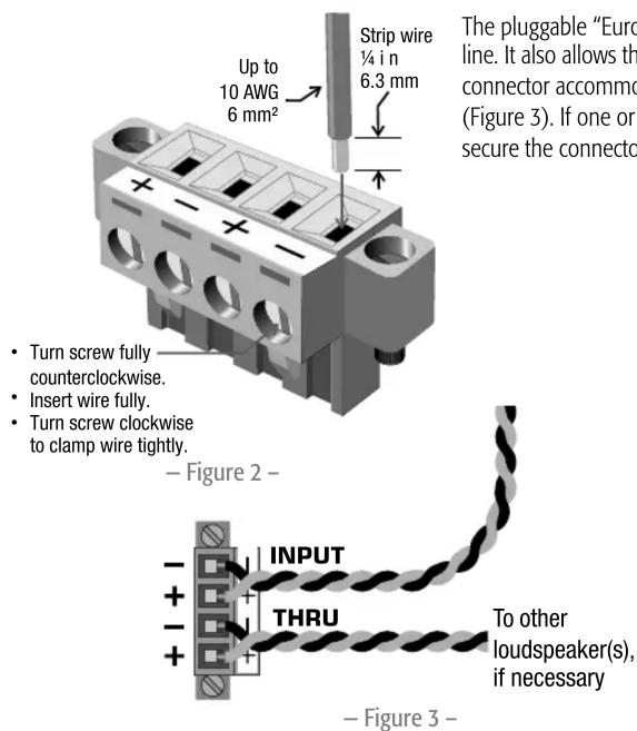
The pluggable "Eurostyle" input connector (Figure 2) has four terminals to facilitate connection on a distributed line. It also allows the installer to pre-wire the venue before the loudspeakers themselves are installed. The connector accommodates wire up to 10 AWG or 6mm^2 . Be sure of proper and consistent polarity at each connector (Figure 3). If one or more loudspeakers is out of polarity with others, the acoustic performance will suffer. Always secure the connector to the loudspeaker using the retaining screws at both ends.
Mounting
Tilt/Swivel Bracket
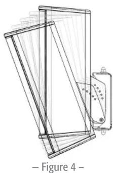
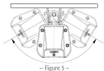
The bracket provided with the loudspeaker allows 0, 5, 10, 15, and 20 degrees of downward tilt (Figure 4), and up to ±55 degrees of horizontal panning (Figure 5). These angles may be constrained by the loudspeaker enclosure and adjacent walls or other structural elements. In addition, the bracket can be inverted, which allows the loudspeaker to be tilted up.
natural_image
Technical line drawing of a mechanical component with no visible text or symbols
natural_image
Technical line drawing of a mechanical component with no visible text or symbols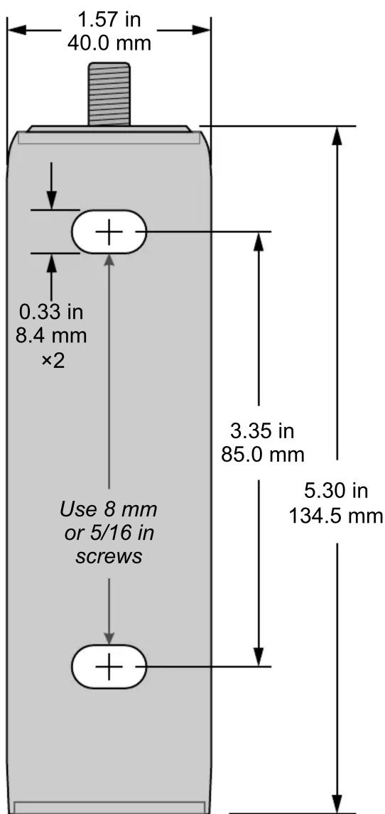
– Figure 8 –
For mounting that requires no panning left or right, the bracket kit includes a zero-pan locking screw to keep the loudspeaker securely in place.
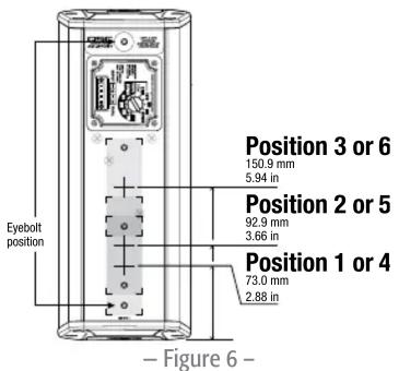
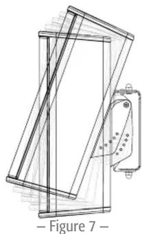
The AD-S402T has three attachment locations for the bracket. Figure 6 shows their center points, including distances from the bottom edge of the enclosure. Two M6 × 20 screws with flat washers are included for attaching the bracket to the rear panel of the enclosure. Inverting the bracket offers three more configurations to choose from and allows the loudspeaker to be tilted up instead of down (Figure 7). In addition, the loudspeaker enclosure itself can be inverted, which doubles the total number of mounting possibilities—exclusive of tilt—to 12.
An M6 eyebolt is included with the loudspeaker for attaching a safety tether, as may be required by building codes in your jurisdiction. Attach the eyebolt securely to the end mounting hole or to one of the unused ones.
The table below describes the pan range for different bracket positions and tilt angles.
| AD-S402T Maximum Pan Range | ||||||
| Bracket Position | 0^ tilt 5^ | tilt 10^ | tilt 15^ tilt | 20^ tilt | Tilt bracket removed | |
| 1 | ± 55^ ± 55^ ± 55^ ± 54^ ± 54^ N/A | |||||
| 2 | ± 55^ ± 54^ ± 53^ ± 51^ ± 49^ ± 50^ | |||||
| 3 | ± 55^ ± 51^ ± 46^ ± 40^ ± 32^ ± 50^ | |||||
| 4 (1 inverted) | ± 55^ ± 45^ ± 29^ ± 7^ N/A N/A | |||||
| 5 (2 inverted) | ± 55^ ± 46^ ± 33^ ± 15^ N/A N/A | |||||
| 6 (3 inverted) | ± 55^ ± 50^ ± 43^ ± 63^ ± 22^ ± 50^ | |||||
Attaching the wall piece
Attach the wall piece to the wall or other mounting surface. Figure 8 is a full-size template. Consult a structural engineer for guidance in selecting mounting locations and appropriate fasteners.

NOTE: To use Figure 8 as a template, print this page at actual size (i.e., with no scaling).
- Figure 9 -
– Figure 10 –
– Figure 11 –
natural_image
Diagram of a door panel with attached sensors and wiring, showing no text or symbols– Figure 12 –
Attaching the loudspeaker bracket pieces to allow tilting
- Select the appropriate attachment location for the bracket on the enclosure rear panel. Note that because of the wall or mounting surface, in most cases the lowest attachment location offers the widest range of tilt options, while the highest offers few, if any, tilt options.
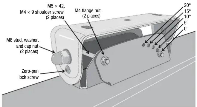
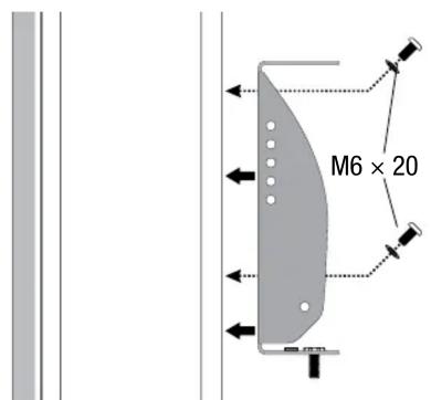
- Use two M6×20 screws and their washers to secure the bracket to the enclosure. Note that the bracket has four mounting holes; some attachment locations use the long-spaced holes and some use the shorter ones.
NOTE: For convenience reasons we recommend configuring the tilt angle (Figure 9) before the loudspeaker and bracket are attached to the wall piece. However, you can adjust the tilt later, even after the loudspeaker has been installed.
- Continue to Attaching the loudspeaker to the wall piece.
Attaching the loudspeaker bracket pieces for no-tilt mounting
If the application does not require tilting the loudspeaker, you can either configure it for 0 degrees or you can simplify the mounting bracket.
To simplify the mounting bracket, follow these steps
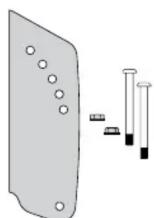
- Omit these parts of the bracket kit, shown in Figure 10.
-
Attach this remaining part of the bracket directly to the loudspeaker enclosure (see below left), using the two M6 × 20 screws (Figure 11).
-
Continue to Attaching the loudspeaker to the wall piece.
Attaching the loudspeaker to the wall piece
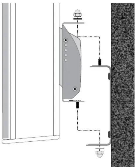
- The wall piece has a stud on the top and the loudspeaker bracket piece has a stud on the bottom. Set the hole in the loudspeaker bracket piece over the wall piece's stud and guide the loudspeaker bracket's stud through the hole in the wall piece (Figure 12).
- Set the loudspeaker onto the wall piece.
- Install a washer and cap nut on each stud and tighten them finger tight.
- Adjust the horizontal pan of the loudspeaker as needed.
- If the loudspeaker's desired horizontal angle is perpendicular to the wall, you may install the zero-pan locking screw to keep it from moving out of position. Make sure that the threaded hole in the loudspeaker bracket piece lines up with the hole in the wall piece, then insert and tighten the screw.
- Tighten the cap nuts securely.
natural_image
Simple line drawing of a rectangular frame with two hanging rings and arrows indicating downward forces (no text or symbols)– Figure 13 –
Horizontal Suspension
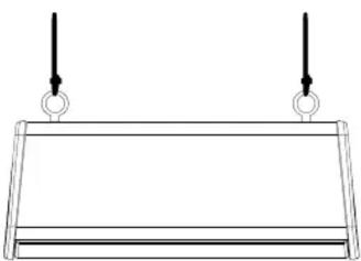
The loudspeaker can also hang horizontally, facing down (Figure 13). Install two M6 eyebolts into the holes at each end of the rear panel. The loudspeaker comes with one clear finish eyebolt; additional eyebolts are available from QSC Technical Services Group: QSC part # HW-000323-01.
Each suspension line and the structural member it is attached to must be rated adequately in accordance with local codes. Consult a structural engineer for guidance.
– Figure 14 –
Power Selection
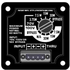
Use the selector switch in the input cup to either select the desired power for the loudspeaker or bypass the transformer altogether and directly connect the loudspeaker as a low impedance load. See Figure 14. The switch is labeled for both 70 and 100-volt lines.
After you have completed the power selection, install the weather cover, if necessary.
WARNING
Read and follow these instructions carefully. If the loudspeakers are not suspended properly they could fall, causing personal injury and damage.
Rules for Suspension
- Consult a professional mechanical or structural engineer—who is licensed in the jurisdiction of the sound system installation—to review, verify, and approve all attachments to the building or structure.
- Employ the services of a professional rigger for hoisting, positioning, and attaching the equipment to the supporting structure.
- Use all suspension hardware and components correctly.
- Before installing equipment, always calculate the suspended loads and make sure they do not exceed the limits of any suspension components and hardware.
- Consult local codes and regulations that govern the facility that you install the equipment in and comply with all their requirements for suspended loads.
- Use only the appropriate M6 eyebolts for suspending the loudspeaker.
- Be absolutely certain of the integrity of any structural member intended to support suspended loads. Structural members can have hidden structural weakness.
- Never assume anything! Owner- or third-party-supplied suspension attachment points might not be adequate for suspending the loads.
- Before lifting, always inspect all components (enclosures, suspension brackets, pins, frames, bolts, nuts, slings, shackles, etc.) for cracks, wear, deformation, and corrosion, as well as missing, loose, or damaged parts, which could reduce the strength of the assembly. Discard any worn, defective, or suspect parts and replace them with new appropriately load-rated parts.
Shock Loading
Moving or stopping a load magnifies its static weight, and sudden actions will magnify the static weight greatly. This magnification is called shock loading and it can be dangerous to people and equipment. The effects of shock loading can be instantaneous but can also be gradual, remaining undetected until the equipment becomes visibly damaged or fails. Precautions for shock loading require careful planning, knowing the equipment's suspension requirements, and using proper lifting practices. Shock loading on equipment and structures occurs most often during lifting and installation, but natural forces (winds, earthquakes, and so on) can also impose shock loads that are several times greater than the static load. Therefore, structures and suspension equipment must always be rated at several times the weight of the suspended equipment.
QSC
Mailing Address:
QSC, LLC
1675 MacArthur Boulevard
Costa Mesa, CA 92626-1468 USA
Telephone Numbers:
Main Number: +1 (714) 754-6175
Sales & Marketing: +1 (714) 957-7100 or toll free (USA only) (800) 854-4079
Customer Service: +1 (714) 957-7150 or toll free (USA only) (800) 772-2834
Facsimile Numbers:
Sales & Marketing FAX: +1 (714) 754-6174
Customer Service FAX: +1 (714) 754-6173
World Wide Web:
www.qsc.com
E-mail:
info@qsc.com
service@qsc.com
tech_support@qsc.com
© 2019 QSC, LLC. All rights reserved. QSC and the QSC logo are registered trademarks of QSC, LLC in the U.S. Patent and
Trademark office and other countries. All other trademarks are the property of their respective owners.
http://patents.qsc.com.
- Installation
- AD-S402T Weather Cover
- Input Connector
- Mounting
- Tilt/Swivel Bracket
- Attaching the wall piece
- Attaching the loudspeaker bracket pieces to allow tilting
- Attaching the loudspeaker bracket pieces for no-tilt mounting
- Attaching the loudspeaker to the wall piece
- Horizontal Suspension
- Power Selection
- WARNING
- Rules for Suspension
- Shock Loading
- QSC
Brand : QSC
Model : AD-S402T
Category : Loudspeaker