
Aquos Board PN-L851H - Desktop computer SHARP - Free user manual and instructions
Find the device manual for free Aquos Board PN-L851H SHARP in PDF.


| Product Type | Interactive Display / Desktop Computer |
| Brand | Sharp |
| Model | Aquos Board PN-L851H |
| Screen Size | 85 inches (diagonal) |
| Resolution | 3840 x 2160 (4K UHD) |
| Touch Technology | Infrared (IR) touch, supports finger and touch pen |
| Input Terminals | HDMI (2), DisplayPort (In/Out), D-Sub, USB (3.0/2.0), LAN, RS-232C, Audio In/Out, External Speaker |
| Wireless Connectivity | Wi-Fi (IEEE 802.11ac/a/b/g/n) with detachable antennas |
| Operating System | Android (built-in) + Touch Pen Management Tool (Windows/Mac/Chrome OS support) |
| Power Supply | AC 100-240 V, 50/60 Hz (use supplied power cord only) |
| Power Consumption | Maximum: Not specified; typical: estimated 300-400 W |
| Weight (approx.) | Estimated 50-60 kg (requires at least 4 people for installation) |
| Dimensions (W x H x D) | Not specified; screen size 85 inches |
| Mounting | VESA standard wall mount, backward tilt up to 45°, portrait/landscape support |
| Main Functions | Multi-screen (PIP, PbyP, Quad), touch menu, remote control, freeze, backlight off, schedule timer, HDMI CEC |
| Supplied Accessories | Remote control, touch pens (2), eraser, tray, power cord, USB cable, wireless antennas, speaker covers, CD-ROM |
| Safety Certifications | FCC Class A, EMC compliance with shielded cables, safety precautions for installation |
| Cleaning and Maintenance | Unplug before cleaning; use dry cloth only; avoid liquid cleaners; do not block vents |
| Spare Parts and Repairability | Contact authorized Sharp dealer for service; user-serviceable parts not available |
| General Information | For indoor use; ambient temperature 5°C to 35°C; avoid direct sunlight; max daily use 16 hours |
Frequently Asked Questions - Aquos Board PN-L851H SHARP
User questions about Aquos Board PN-L851H SHARP
0 question about this device. Answer the ones you know or ask your own.
Ask a new question about this device
Download the instructions for your Desktop computer in PDF format for free! Find your manual Aquos Board PN-L851H - SHARP and take your electronic device back in hand. On this page are published all the documents necessary for the use of your device. Aquos Board PN-L851H by SHARP.
USER MANUAL Aquos Board PN-L851H SHARP
To aid reporting in case of loss or theft, please record the product's model and serial numbers in the space provided.
The numbers are located in the rear of the product.
Model No.:
Serial No.:
U.S.A. ONLY
WARNING: TO REDUCE THE RISK OF FIRE OR ELECTRIC SHOCK, DO NOT EXPOSE THIS PRODUCT TO RAIN OR MOISTURE.

CAUTION
RISK OF ELECTRIC SHOCK DO NOT OPEN

CAUTION: TO REDUCE THE RISK OF ELECTRIC SHOCK, DO NOT REMOVE COVER. NO USER-SERVICEABLE PARTS INSIDE. REFER SERVICING TO QUALIFIED SERVICE PERSONNEL.

The lightning flash with arrowhead symbol, within a triangle, is intended to alert the user to the presence of uninsulated “dangerous voltage” within the product’s enclosure that may be of sufficient magnitude to constitute a risk of electric shock to persons.

The exclamation point within a triangle is intended to alert the user to the presence of important operating and maintenance (servicing) instructions in the literature accompanying the product.
WARNING:
FCC Regulations state that any unauthorized changes or modifications to this equipment not expressly approved by the manufacturer could void the user's authority to operate this equipment.
NOTE:
This equipment has been tested and found to comply with the limits for a Class A digital device, pursuant to Part 15 of the FCC Rules. These limits are designed to provide reasonable protection against harmful interference when the equipment is operated in a commercial environment. This equipment generates, uses, and can radiate radio frequency energy and, if not installed and used in accordance with the instruction manual, may cause harmful interference to radio communications. Operation of this equipment in a residential area is likely to cause harmful interference in which case the user will be required to correct the interference at his own expense.
This product utilizes a CR coin Lithium battery which contains a Perchlorate material. Special handling for this material may apply, California residents, See www.dtsc.ca.gov/hazardouswaste/perchlorate/Others, consult local environmental officers.
U.S.A. ONLY
To maintain compliance with EMC regulations, use shielded cables to connect to the following terminals: HDMI input terminal, D-sub input terminal, RS-232C input terminal, and DisplayPort input/output terminals.
Thank you for your purchase of a SHARP LCD product. To ensure safety and many years of trouble-free operation of your product, please read the Safety Precautions carefully before using this product.
SAFETY PRECAUTIONS
Electricity is used to perform many useful functions, but it can also cause personal injuries and property damage if improperly handled. This product has been engineered and manufactured with the highest priority on safety. However, improper use can result in electric shock and/or fire. In order to prevent potential danger, please observe the following instructions when installing, operating and cleaning the product. To ensure your safety and prolong the service life of your LCD product, please read the following precautions carefully before using the product.
- Read instructions — All operating instructions must be read and understood before the product is operated.
- Keep this manual in a safe place — These safety and operating instructions must be kept in a safe place for future reference.
- Observe warnings — All warnings on the product and in the instructions must be observed closely.
- Follow instructions — All operating instructions must be followed.
- Cleaning — Unplug the power cord from the power outlet before cleaning the product. Use a dry cloth to clean the product. Do not use liquid cleaners or aerosol cleaners. Do not use dirty cloths. Doing so may damage the product.
- Attachments — Do not use attachments not recommended by the manufacturer. Use of inadequate attachments can result in accidents.
- Water and moisture — Do not use the product near water. Do not install the product in a place where water may splash onto it. Be careful of equipment which drains water such as an air-conditioner.
-
Ventilation — The vents and other openings in the cabinet are designed for ventilation.
Do not cover or block these vents and openings since insufficient ventilation can cause overheating and/or shorten the life of the product. Do not place the product on a sofa, rug or other similar surface, since they can block ventilation openings. Do not place the product in an enclosed place such as a bookcase or rack, unless proper ventilation is provided or the manufacturer's instructions are followed. -
Power cord protection — The power cords must be routed properly to prevent people from stepping on them or objects from resting on them.
-
The screen used in this product is made of glass. Therefore, it can break when the product is dropped or applied with impact. Be careful not to be injured by broken glass pieces in case the screen breaks.
-
Overloading — Do not overload power outlets or extension cords. Overloading can cause fire or electric shock.
-
Entering of objects and liquids — Never insert an object into the product through vents or openings. High voltage flows in the product, and inserting an object can cause electric shock and/or short internal parts.
For the same reason, do not spill water or liquid on the product.
-
Servicing — Do not attempt to service the product yourself. Removing covers can expose you to high voltage and other dangerous conditions. Request a qualified service person to perform servicing.
-
Repair — If any of the following conditions occurs, unplug the power cord from the power outlet, and request a qualified service person to perform repairs.
a. When the power cord or plug is damaged.
b. When a liquid was spilled on the product or when objects have fallen into the product.
c. When the product has been exposed to rain or water.
d. When the product does not operate properly as described in the operating instructions.
Do not touch the controls other than those described in the operating instructions. Improper adjustment of controls not described in the instructions can cause damage, which often requires extensive adjustment work by a qualified technician.
e. When the product has been dropped or damaged.
f. When the product displays an abnormal condition. Any noticeable abnormality in the product indicates that the product needs servicing.
-
Replacement parts — In case the product needs replacement parts, make sure that the service person uses replacement parts specified by the manufacturer, or those with the same characteristics and performance as the original parts. Use of unauthorized parts can result in fire, electric shock and/or other danger.
-
Safety checks — Upon completion of service or repair work, request the service technician to perform safety checks to ensure that the product is in proper operating condition.
-
Wall mounting — When mounting the product on a wall, be sure to install the product according to the method recommended by the manufacturer.
-
Heat sources — Keep the product away from heat sources such as radiators, heaters, stoves and other heat-generating products (including amplifiers).
-
Batteries — Incorrect use of batteries may cause the batteries to burst or ignite. A leaky battery may corrode the equipment, dirty your hands or spoil your clothing. In order to avoid these problems, make sure to observe the precautions below:
- Use the specified batteries only.
- Install the batteries with due attention to the plus (+) and minus (-) sides of the batteries according to the instructions in the compartment.
- Do not mix old and new batteries.
- Do not mix batteries of different types. Voltage specifications of batteries of the same shape may vary.
- Replace an exhausted battery with a new one promptly.
- If you will not use the remote control for a long time, remove the batteries.
- If leaked battery fluid gets on your skin or clothing, rinse immediately and thoroughly. If it gets into your eye, bathe your eye well rather than rubbing and seek medical treatment immediately. Leaked battery fluid that gets into your eye or your clothing may cause a skin irritation or damage your eye.
-
Usage of the monitor must not be accompanied by fatal risks or dangers that, could lead directly to death, personal injury, severe physical damage or other loss, including nuclear reaction control in nuclear facility, medical life support system, and missile launch control in a weapon system.
-
Do not stay in contact with the parts of the product that become hot for long periods of time. Doing so may result in low-temperature burns.
-
Do not modify this product.
WARNING:
This is a Class A product. In a domestic environment this product may cause radio interference in which case the user may be required to take adequate measures.
An apparatus with CLASS I construction shall be connected to a MAIN socket outlet with a protective earthing connection.
STABILITY HAZARD
If a monitor is not positioned in a sufficiently stable location, it can be potentially hazardous due to falling. Many injuries, particularly to children, can be avoided by taking simple precautions such as:
- Using fixing devices like wall mount brackets recommended by the manufacturer.
- Only using furniture that can safely support the monitor.
- Ensuring the monitor is not overhanging the edge of the supporting furniture.
- Not placing the monitor on tall furniture (for example, cupboards or bookcases) without anchoring both the furniture and the monitor to a suitable support.
- Not standing the monitors on cloth or other materials placed between the monitor and supporting furniture.
• Educating children about the dangers of climbing on furniture to reach the monitor or its controls. - This equipment is not suitable for use in locations where children are likely to be present unsupervised.
Especially for child safety
- Don't allow children to climb on or play with the monitor.
- Don't place the monitor on furniture that can easily be used as steps, such as a chest of drawers.
- Remember that children can become excited while watching a program, especially on a “larger than life” monitor. Care should be taken to place or install the monitor where it cannot be pushed, pulled over, or knocked down.
- Care should be taken to route all cords and cables connected to the monitor so that they cannot be pulled or grabbed by curious children.
- The TFT color LCD panel used in this monitor is made with the application of high precision technology. However, there may be minute points on the screen where pixels never light or are permanently lit. Also, if the screen is viewed from an acute angle there may be uneven colors or brightness. Please note that these are not malfunctions but common phenomena of LCDs and will not affect the performance of the monitor.
- Do not display a still picture for a long period, as this could cause a residual image.
- Never rub or tap the monitor with hard objects.
- Please understand that SHARP CORPORATION bears no responsibility for errors made during use by the customer or a third party, nor for any other malfunctions or damage to this product arising during use, except where indemnity liability is recognized under law.
- This monitor and its accessories may be upgraded without advance notice.
- Do not use the monitor where there is a lot of dust, where humidity is high, or where the monitor may come into contact with oil or steam. Do not use in an environment where there are corrosive gases (sulfur dioxide, hydrogen sulfide, nitrogen dioxide, chlorine, ammonia, ozone, etc.). As this could lead to fire.
- Ensure that the monitor does not come into contact with water or other fluids. Ensure that no objects such as paper clips or pins enter the monitor as this could lead to fire or electric shock.
- Do not place the monitor on top of unstable objects or in unsafe places. Do not allow the monitor to receive strong shocks or to strongly vibrate. Causing the monitor to fall or topple over may damage it.
- Do not use the monitor near heating equipment or in places where there is likelihood of high temperature, as this may lead to generation of excessive heat and outbreak of fire.
- Do not use the monitor in places where it may be exposed to direct sunlight. Risk of cabinet deformation and failure if the monitor is used in direct sunlight.
- Please be sure to constantly remove dust and garbage that has attached to the ventilation opening. If dust collects in the ventilation opening or the inside of the monitor, it may lead to excessive heat, outbreak of fire, or malfunction. Please request a cleaning of the inside of the monitor from an authorized SHARP servicing dealer or service center.
- When using this monitor in a portrait orientation, prepare portrait-oriented content in advance.
- The power outlet shall be installed near the equipment and shall be easily accessible.
- Continuous operating time and warranty. This product is designed for a maximum daily use of 16 hours. Continual use in excess of 16 hours per day is not covered by the warranty.
- Do not touch the screen when the monitor power is turned on, it will lead to a malfunction. When this occurs, turn the monitor power off and then on.
- Do not operate the screen with a hard or pointed object such as a fingernail or pencil.
- Depending on the application used, the touch pen may not function.
- If another USB device is connected to the computer to which the touch panel is connected, do not operate the USB device during touch panel input. Input may not take place correctly.
- Restarting the Android system. To maintain stable operation of APPLICATION mode, the Android system must be restarted once a day. A schedule is set by factory default in this monitor that restarts the system at 3:00 AM. (See the "APPLICATION Mode Reboot" of Software Guide.)
- If you or a third party uses the product incorrectly, or if the product is subjected to the effects of static electricity or electrical noise, or if the product malfunctions or is repaired, there is a risk that saved data will be corrupted or lost.
- Always back up important data to a USB flash drive or microSD memory card.
- We bear no responsibility for protection of internal memory recorded content or related damages.
The Power Cord
- Use only the power cord supplied with the monitor.
- Do not damage the power cord nor place heavy objects on it, stretch it or over bend it. Also, do not add extension cords. Damage to the cord may result in fire or electric shock.
- Do not use the power cord with a power tap.
Adding an extension cord may lead to fire as a result of overheating.
- Do not remove or insert the power plug with wet hands. Doing so could result in electric shock.
- Unplug the power cord if it is not used for a long time.
- Do not attempt to repair the power cord if it is broken or malfunctioning. Refer the servicing to the service representative.
Manual Scope
- Microsoft and Windows are either registered trademarks or trademarks of Microsoft Corporation in the United States and/or other countries.
- Apple, Mac and macOS are trademarks of Apple Inc., registered in the U.S. and other countries.
- The terms HDMI, HDMI High-Definition Multimedia Interface, and the HDMI Logo are trademarks or registered trademarks of HDMI Licensing Administrator, Inc.
- DisplayPort is a registered trademark of Video Electronics Standards Association.
- Intel, Celeron, and Intel Core are trademarks or registered trademarks of Intel Corporation or its subsidiaries in the U.S.A. and other countries.
- Google, Chrome OS and Android are trademarks or registered trademarks of Google LLC.
- Ethernet is a registered trademark of Xerox Corporation.
- VESA is either registered trademark or trademark of Video Electronics Standards Association in the United States and/or other countries.
- All other brand and product names are trademarks or registered trademarks of their respective holders.
- This product comes with RICOH Bitmap Fonts produced and sold by RICOH COMPANY, LTD.
- Language of OSD menu used in this manual is English by way of example.
- Illustrations in this manual may not exactly represent the actual product or display.
- This manual assumes use in landscape orientation, except where specifically noted.
LED Backlight
- The LED backlight in this product has a limited lifetime.
* If the screen gets dark or does not turn on, it may be necessary to replace the LED backlight.
* This LED backlight is exclusive to this product and must be replaced by an authorized SHARP servicing dealer or service center. Please contact an authorized SHARP servicing dealer or service center for assistance.
• This product is for use indoors.
- A mounting bracket compliant with VESA specifications is required.
- Since the monitor is heavy, consult your dealer before installing, removing or moving the monitor.
- Mounting the monitor on the wall requires special expertise and the work must be performed by an authorized SHARP dealer. You should never attempt to perform any of this work yourself. Our company will bear no responsibility for accidents or injuries caused by improper mounting or mishandling.
- Use the monitor with the surface perpendicular to a level surface. If necessary, the monitor may be tilted up to 20 degrees upward.
- When using PN-L851H tilted upward from the perpendicular in relation to a level surface, consult an authorized SHARP dealer because there are some specific mounting conditions.
- When moving the monitor, be sure to hold the handles or the parts marked by □ below. Do not grasp the screen or tray. This may cause product damage, failure, or injury.

natural_image
Top-down schematic of a rectangular electronic device with internal compartments and mounting brackets (no text or symbols)- This monitor should be used at an ambient temperature between 41°F (5°C) and 95°F (35°C). Provide enough space around the monitor to prevent heat from accumulating inside.
For the monitor in landscape orientation
![7-7/8 [200] 2 [50] 2 [50] 2 [50] Unit: inch [mm] 1-7/16 [35]](/content/2026/05/820587/images/bf5b9f2a3965fb34c30c59a676cbf4cd765d5434bf33a791bf386ee6db1748ef.jpg)
For the monitor in portrait orientation
![7-7/8 [200] 2 [50] 2 [50] 2 [50] Power LED Unit: inch [mm] 1-7/16 [35]](/content/2026/05/820587/images/f7a106d93064df048297ee05b8c68d88e5b405d5e0bbd559c6a67a1743bad423.jpg)
- If it is difficult to provide sufficient space for any reason such as the installation of the monitor inside a housing or of several units side-by-side, or if the ambient temperature may be outside of the range of 41°F (5°C) to 95°F (35°C), install a fan or take other measures to keep the ambient temperature within the required range.
- When installing two or more monitor units side-by-side, provide space of at least 3/16 inch (5 mm) around them to prevent stress on the adjacent unit or structure due to thermal expansion.
-
Temperature condition may change when using the monitor together with the optional equipments recommended by SHARP. In such cases, please check the temperature condition specified by the optional equipments.
-
Do not block any ventilation openings. If the temperature inside the monitor rises, this could lead to a malfunction.
- Do not place the monitor on a device which generates heat.
- Do not use the product in locations where the unit is exposed to direct sunlight or other strong light. Since this product operates with infrared rays, such light may cause a malfunction.
- When using multiple monitors closely, be sure the infrared transmitter/receiver does not affect the other ones.
- Adhere to the following when installing the monitor in its portrait orientation. Failing to adhere to the following may cause malfunctions.
- Install the monitor such that the power LED is located on the bottom side.
- Set the PORTRAIT/LANDSCAPE INSTALL in the MONITOR menu to PORTRAIT. (See page 36.)
- Be sure to clamp the power cord (supplied) onto the cable clamp attachment using the supplied cable clamp. When clamping the power cord, take care not to stress the terminal of the power cord. Do not bend the power cord excessively.
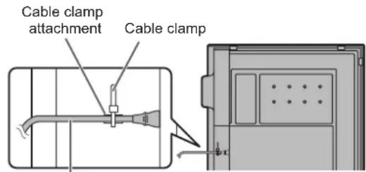
Power cord (Supplied)
- Use the supplied vertical sticker when you install the monitor in portrait orientation.

flowchart
graph TD
    A["Cover SHARP logo"] --> B["SHARP logo"]
    B --> C["Arrow indicating transformation"]
Backward tilt installation
- When using this monitor tilted more than 20 degrees upward from the perpendicular in relation to a level surface, consult an authorized SHARP dealer because there are some specific mounting conditions.
Adhere to the following. Failing to adhere to the following may cause malfunctions.
- This monitor can be tilted up to 45 degrees upward.
- Set BACKWARD TILT INSTALLATION in the MONITOR menu to ON. (See page 36.)
- Use this monitor at the ambient temperature between 41°F (5°C) and 86°F (30°C). Provide 7-7/8 inch (200 mm) or more space between the monitor and the floor or other mounting surfaces and surrounding objects to prevent heat from accumulating inside.
If it is difficult to provide sufficient space or if the ambient temperature may be outside of the range of 41^ F ( 5^ C) to 86^ F ( 30^ C), install a fan or take other measures to keep the ambient temperature within the required range.
![7-7/8 [200] 7-7/8 [200] 7-7/8 [200] Unit: inch [mm] 7-7/8 [200]](/content/2026/05/820587/images/349c8d3a20035c86c429c467188b00ed2a879b1fa6f4cecd23d3e52b6f609fb7.jpg)
- Do not press hard on the screen or otherwise subject it to impacts.
Contents
IMPORTANT INFORMATION......3
DEAR SHARP CUSTOMER....4
SAFETY PRECAUTIONS......4
TIPS AND SAFETY INSTRUCTIONS....6
MOUNTING PRECAUTIONS....7
Supplied Components....10
System Requirements....10
Part Names ...... 11
Connecting Peripheral Equipment....13
Connecting the Power Cord ....15
Binding Cables....15
Preparing the Remote Control Unit....16
Installing the batteries ....16
Remote control operation range....16
Removing the Handles....17
Mounting a web camera....17
Attaching the USB flash drive / SD card cover .....18
Attaching the wireless LAN antenna ....18
Turning Power On/Off....19
Turning on the main power....19
Turning power on/off 19
Touch Pen....21
Touch action....22
Touch action....22
Other functions....24
Cautionary points 24
Eraser....24
Basic Operation 25
Using the touch menu 25
Using the remote control unit 26
Menu Items....29
Displaying the menu screen....29
Configuring settings in the touch menu....30
Menu item details....31
Adjustments for computer screen display ....42
Initialization (Reset)/Functional Restriction Setting
(FUNCTION)......43
Controlling the Monitor with a computer (RS-232C)...45
Computer connection 45
Communication conditions....45
Communication procedure 45
RS-232C command table....47
Controlling the Monitor with a computer (LAN)....53
Command-based control....53
Troubleshooting....54
Specifications 56
Mounting Precautions
(For SHARP dealers and service engineers)....60
Supplied Components
If any component should be missing, please contact your dealer.
□ Liquid Crystal Display Monitor: 1
□ Remote control unit: 1
□ Cable clamp: 2
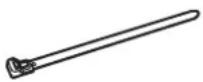
□ Cable clamp (affixing type): 3

□ Power cord: 1
☐ R03 battery ("AAA" size): 2
☐ CD-ROM (Utility Disk for Windows): 1
☐ SHARP Display Connect License: 1
□ Setup Manual: 1
□ Specification sheet
☐ Touch pen: 1 (PN-L851H: 2)
□ Eraser: 1
□ Tray: 1
☐ USB flash drive / SD card cover: 1
□ Speaker cover: 2
□ Camera mount: 1
□ Tray mounting screws,
Speaker cover attachment screws (M3x10): 9
☐ Camera mount screws (M3x5): 2
☐ USB flash drive / SD card cover fixing screw (knurled screw): 1
☐ Camera screw (inch thread): 1
□ Wireless LAN antenna: 2
□ USB cable: 1
□ Vertical sticker (Logo): 1
□ Cover SHARP logo: 1
Place this sticker onto the SHARP logo to cover the logo.
* SHARP Corporation holds authorship rights to the Utility Disk program. Do not reproduce it without permission.
* For environmental protection!
Do not dispose of batteries in household waste. Follow the disposal instructions for your area.
System Requirements
| Hardware | Must have a USB 2.0 compliant port.CD-ROM drive required for software installation. |
| Operating system | Windows 8.1 (32-bit or 64-bit version), Windows 10 (32-bit or 64-bit version) |
| macOS v10.13, v10.14(The touch panel and touch pen operate with the standard driver of operating system.) | |
| Google Chrome OS Version 59 or later(The touch panel and touch pen operate with the standard driver of operating system.) |
Requirements when the software (Windows) supplied with this monitor is used.
| CPU | Intel Core i5-6360U or fasterIntel Core i7-6650U or faster recommended |
| Video Output Must be capable of output at a Vsync of 60 Hz or higher | |
| Memory At least 4 GB | |
| Free space on hard drive At least 5 GB (free space separately required for data storage) | |
To use a touch panel with a computer connected to the video input terminal on this monitor, TOUCH PANEL1 terminal on the side and computer must be connected using the supplied USB cable, and Touch pen Management Tool must be installed on the computer from the supplied CD-ROM. (Factory setting)
To use the TOUCH PANEL2 terminal on the bottom, change the setting for the terminal used in TOUCH INPUT SELECT in the SETUP menu to TOUCH PANEL2.
Install Pen Software from the supplied CD-ROM.
When the Information Display Downloader is installed, you can check and download the most recent versions of the software programs.
To install the software, see the manual for each.
Touch Viewer setup program and SHARP Display Connect setup program can be downloaded using Information Display Downloader.
Part Names
■Front view

■Rear view
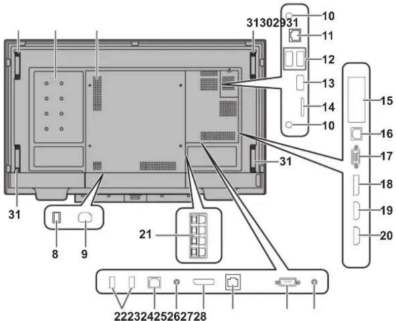
-
Remote control sensor (See page 16.)
-
Power LED (See page 19.)
-
POWER button (See page 19.)
-
TOUCH MENU button (See page 25.)
-
Tray
-
Speakers
-
Infrared transmitter/receiver
-
Main power switch (See page 15.)
-
AC input terminal (See page 15)
-
Wireless LAN antenna terminal (See page 14.)
11.LAN terminal (See page 14.)
-
USB port (USB 3.0 compliant) (See page 14.)
-
USB port (USB 2.0 compliant) (See page 14.)
-
microSD card slot (See page 14.)
-
Expansion slot
This section is used to connect optional hardware for function expansion. Offering this attachment location is not a guarantee that future compatible hardware attachments will be released.
-
TOUCH PANEL1 terminal (for touch panel) (See page 14.)
-
D-sub input terminal (See page 13.)
-
DisplayPort input terminal (See page 13.)
-
HDMI1 input terminal (See page 13.)
-
HDMI2 input terminal (See page 13.)
-
External speaker terminals (See page 14.)
-
USB hub (for computer) (USB 2.0 compliant) (See page 14.)
-
TOUCH PANEL2 terminal (for touch panel) (See page 14.)
-
Audio output terminal (See page 14.)
-
DisplayPort output terminal (See page 14.)
-
Optional terminal
This terminal is provided for possible future (optional) function expansion. Offering of this terminal is not a guarantee that future expanded functionality will be released.
-
RS-232C input terminal (See page 13.)
-
Audio input terminal (See page 13.)
-
Optional attachment section
This section is used to connect optional hardware for function expansion. Offering this attachment location is not a guarantee that future compatible hardware attachments will be released.
-
Vents
-
Handles
TIPS
- It is possible to use the terminals for separate purposes; for example, using the TOUCH PANEL2 terminal to connect a fixed computer and using the TOUCH PANEL1 terminal to connect a mobile computer.
To use the TOUCH PANEL2 terminal, change the setting for the terminal used in TOUCH INPUT SELECT in the SETUP menu to TOUCH PANEL2.
! Caution
- Consult your SHARP dealer for attachment/detachment of optional parts.
■Remote control unit

- Signal transmitter
- Operation buttons (See page 26.)
Connecting Peripheral Equipment

! Caution
- Be sure to turn off the main power switch and disconnect the plug from the power outlet before connecting/disconnecting cables. Also, read the manual of the equipment to be connected.
- Be careful not to confuse the input terminal with the output terminal when connecting cables. Accidentally reversing cables connected to the input and output terminals may cause malfunctions and the other problems.
- Do not use any cable that has a damaged or deformed terminal. Using such cables may cause malfunctions.
TIPS
- When using a touch panel with a computer connected to the video input terminal on this monitor, connect the USB cable to the computer. For details, see the Touch pen Management Tool Operation Manual.
• Images may not be displayed properly depending on the computer (video card) to be connected. - Use the automatic screen adjustment when a computer screen is displayed for the first time using D-SUB or when the setting of the computer is changed. The screen is adjusted automatically when SELF ADJUST in the MONITOR menu is set to ON.
- If the audio output from the playback device is connected directly to speakers or other devices, the video on the monitor may appear delayed from the audio portion. Audio should be played through this monitor by connecting the playback device to the monitor's audio input, and connecting the monitor's audio output to the speakers or other devices.
- The audio input terminals used in each input mode are factory-set as follows.
| Input mode | Audio input terminal (Factory setting) |
| DisplayPort DisplayPort input | terminal |
| HDMI1 HDMI1 input terminal | |
| HDMI2 HDMI2 input terminal | |
| D-SUB Audio input terminal |
-
HDMI1 input terminal
-
HDMI2 input terminal
- Use a commercially available HDMI cable (conforming to the HDMI standard) that supports 4K.
- Select the audio input terminal to be used in AUDIO SELECT of the SETUP menu. When HDMI is selected, it is not necessary to connect an audio cable to the audio input terminal.
- DisplayPort input terminal
- Use a commercially available DisplayPort cable (conforming to the DisplayPort standard) that supports 4K.
- Select the audio input terminal to be used in AUDIO SELECT of the SETUP menu. When DisplayPort is selected, it is not necessary to connect an audio cable to the audio input terminal.
-
D-sub input terminal
-
Audio input terminal
• Use an audio cable without resistance.
- Set the audio input terminal to be used in each input mode in AUDIO SELECT on the SETUP menu.
- RS-232C input terminal
- You can control the monitor from a computer by connecting a commercially available RS-232 straight cable between these terminals and the computer.
Connecting Peripheral Equipment
7. DisplayPort output terminal
- The screen displayed on this monitor and the audio output from this monitor can be output to an external device.
- Use a commercially available DisplayPort cable (conforming to the DisplayPort standard) that supports 4K.
- Outputting HDCP-encrypted video requires an external device which supports HDCP.
TIPS
- The length of the signal cables or surrounding environment may affect the image quality.
• Video output is disabled in the following cases: When the power is turned off.
When the monitor is in input signal waiting mode.
• This terminal does not support HDR signals.
The output device's screen will not be displayed properly.
8. Audio output terminal
• The output sound varies depending on the input mode.
- The volume of the output sound can be fixed by setting AUDIO OUTPUT of AUDIO OPTION on the SETUP menu.
- It is not possible to control the sound output from the audio output terminals with the AUDIO menu.
9. Wireless LAN antenna terminal
- Attach the supplied wireless LAN antennas.
10. LAN terminal
- You can control the monitor from a computer on a network by connecting a commercially available LAN cable between this terminal and a network.
11.USBport
- This is used in APPLICATION mode. For details, see the Software Guide.
12. microSD card slot
- This is used in APPLICATION mode. For details, see the Software Guide.
13. USB hub (for computer) (USB 2.0 compliant)
- You can connect a commercially available USB mouse or USB keyboard as a USB hub of the computer connected to TOUCH PANEL1 terminal / TOUCH PANEL2 terminal*.
* When the input mode is changed, this will change to the terminal set with TOUCH INPUT SELECT on the SETUP menu.
! Caution
- Do not connect a storage device such as a hard drive or memory device. When the input mode is changed, the connection will be broken and data may be corrupted.
14. TOUCH PANEL1 terminal (for touch panel)
15. TOUCH PANEL2 terminal (for touch panel)
- To use the touch panel with a computer, connect the touch panel to the computer with a USB cable.
- In TOUCH INPUT SELECT on the SETUP menu, you can set the terminal connected to the computer for each input mode.
- It is possible to use the terminals for separate purposes; for example, using the TOUCH PANEL2 terminal to connect a fixed computer and using the TOUCH PANEL1 terminal to connect a mobile computer.
To use the TOUCH PANEL2 terminal, go to the SETUP menu and change the TOUCH INPUT SELECT setting for the terminal used to TOUCH PANEL2.
16. External speaker terminals
• To use external speakers, set SPEAKER SELECT to EXTERNAL in AUDIO OPTION on the SETUP menu.
- Be sure to use external speakers with an impedance of 6 Ω or greater and a rated input of at least 10 W.

-
While pushing the tab, insert the tip of the cable.
-
Release the tab.
TIPS
- Be sure to connect the + and - terminals and the left and right speakers properly.
- Avoid short circuiting the + and - terminals.
- When SPEAKER SELECT is set to EXTERNAL, the internal speakers are disabled.
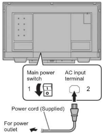
Connecting the Power Cord
!Caution
• Use only the power cord supplied with the monitor.
- Turn off the main power switch.
- Plug the power cord (supplied) into the AC input terminal.
- Plug the power cord (supplied) into the power outlet.
Binding Cables
The supplied cable clamps can be used to clamp the power cord and cables connected to the back of the monitor.

natural_image
Top-down schematic of a TV or audio workstation layout with no visible text, numbers, or symbols
Attach the supplied cable clamps (affixing type) to a flat surface, removing any dust or dirt before attaching. Do not attach over a vent.

Preparing the Remote Control Unit
Installing the batteries
- Place your finger on the part marked with the ▲, and then pull the cover off.

natural_image
Line drawing of a remote control device with a circular component and directional arrow (no text or symbols)-
See the instructions in the compartment and put in the supplied batteries (R03 ("AAA" size) x 2) with their plus (+) and minus (-) sides oriented correctly.
-
Close the cover.
TIPS
- When the batteries become exhausted, replace them with new (commercially available) batteries.
- The supplied batteries may become exhausted quickly depending on how they are stored.
- If you will not be using the remote control for a long time, remove the batteries.
• Use manganese or alkaline batteries only.
Remote control operation range
The operation range of the remote control unit is approx. 16.4 feet (5 m) at an angle of approx 10^ from the center to the top/bottom/right/left of the remote control sensor.
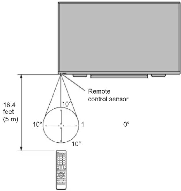
TIPS
- Do not expose the remote control unit to shock by dropping or stepping on it. This could lead to a malfunction.
- Do not expose the remote control unit to liquids, and do not place it in an area with high humidity.
- The remote control unit may not work properly if the remote control sensor is under direct sunlight or strong lighting.
- Objects between the remote control unit and the remote control sensor may prevent proper operation.
- Replace the batteries when they run low as this may shorten the remote control's operation range.
- If a fluorescent light is illuminated near the remote control unit, it may interfere with proper operation.
- Do not use it with the remote control of other equipment such as air conditioner, stereo components, etc.
Removing the Handles
The handles can be removed.
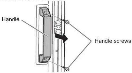
!Caution
- The removable handles and handle screws are for use with this monitor. Do not use them for any other devices.
- To attach handles, be sure to use the handles and handle screws which were removed from this monitor.
- Be sure the handles are attached securely.
Mounting a web camera
It is possible to mount a commercially available web camera in the following positions:

(1) Attach the supplied camera mount with the supplied camera mount screws (M3x5) (x2).
(2) Attach the web camera (commercially available) to the camera mount with the supplied camera screw (inch thread) (x1).
* The camera mount cannot be attached when the tray is attached.
Mounting on the tray
Attach the web camera to the mounting hole on the right or left side of the tray with the supplied camera screw (inch thread) (x1).
Attaching the USB flash drive / SD card cover
- Attach the USB flash drive / SD card cover (supplied) to this monitor.
USB flash drive / SD card cover (supplied)
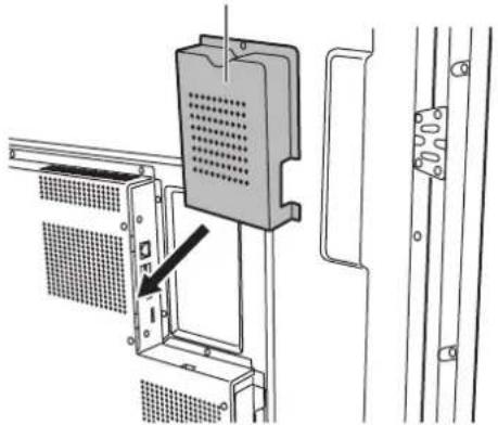
natural_image
Technical line drawing of a mechanical assembly with mounting brackets and a panel, showing no text or symbols.- Secure the cover using USB flash drive / SD card cover fixing screw (knurled screw) (supplied).

natural_image
Technical line drawing of a mechanical component with mounting brackets and internal structure (no text or symbols)USB flash drive /
SD card cover fixing screw (knurled screw) (supplied)
TIPS
- If the cover will be attached, use a USB flash drive no larger than 2-3/4 inch (70 mm) (L) (excluding the terminal) x 11/16 inch (17 mm) (W) x 5/16 inch (8 mm) (H).

Attaching the wireless LAN antenna

Turning Power On/Off
!Caution
- Turn on the monitor first before turning on the computer or playback device.
- When switching the main power switch or the POWER button off and back on, always wait for at least 5 seconds. A short interval may result in a malfunction.
Turning on the main power
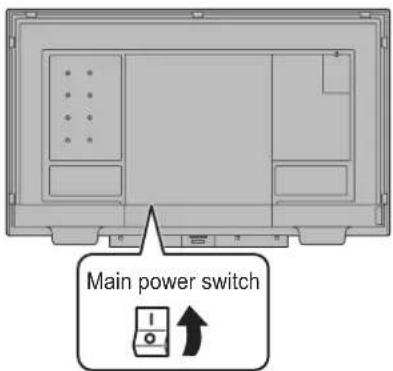
!Caution
- The main power must be turned on/off with the main power switch. Do not connect/disconnect the power cord or turn the breaker on/off while the main power switch is on.
- For a complete electrical disconnection, pull out the main plug.
Turning power on/off
Press the POWER button to turn the power ON/OFF. You can also turn the power ON/OFF by pressing the MONITOR ON button/MONITOR OFF button on the remote control unit.


| Status Status of the monitor | |
| Blue lit Power on | |
| Orange lit Power off (Standby mode) | |
| Blue flashing Input signal waiting mode | |
TIPS
- When the main power switch is off, the monitor cannot be turned on.
- If the monitor is in the input signal waiting mode and you press the POWER button or MONITOR OFF button, the monitor enters standby mode.
- Setting the SCHEDULE flashes the power LED in orange in standby mode.
- To disable the logo screen from displaying when turning the power ON, set LOGO SCREEN to OFF on the OTHERS menu. (See page 38.)
- You can fix the input mode that appears after startup. Set START INPUT MODE on the SETUP menu. (See page 35.)
!Caution
- When the power is turned off, any data in Direct Drawing for Android is lost.
If Direct Drawing for Android is running, a message will appear. Save any data you need. - If the monitor will be turned off by SCHEDULE, OFF IF NO OPERATION, RS-232C control or LAN control, save any data you need in advance. The power will turn off even if there is unsaved data. (The data will be lost.)
■Operations after first power-on
Set POWER SAVE MODE
When the monitor is turned on for the first time after being shipped from the factory, the power save mode setting screen will be displayed. Set it to YES or NO.
YES ..... POWER SAVE MODE is set to ON. Current consumption is reduced while the monitor is in standby mode. Android is also shut down. Note, however, that the startup time from standby mode becomes longer.
NO ..... POWER SAVE MODE is set to OFF. Startup time from standby mode is reduced. Note, however, that more power will be consumed in standby mode. Android continues to run in standby mode.
Even after being set, you can change the POWER SAVE MODE. (See page 36.)
Set the date/time
The date/time setting screen appears.
![DATE/TIME SETTING --/---/---- -- :---:-- The date/time setting must be set by APPLICATION. [SET] : Display "Date & time" on APPLICATION SET RANCEL OK:[ENTER] END:[RETURN]](/content/2026/05/820587/images/9a66dc0ae91295e055a89a210b5b6bcf8a49b86e1be06e6b5ad256f747e5472d.jpg)
1. Select "SET".
The input mode changes to APPLICATION, and the "Date & time" screen appears.
2. Select "Set date".
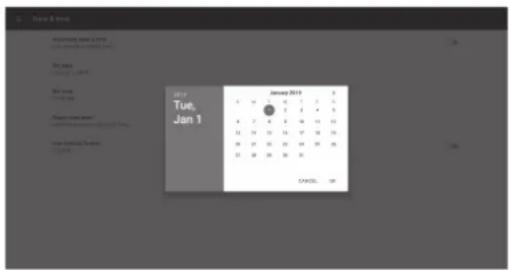
3. Set the date and select "OK".
The "Date & time" screen appears.
4. Select "Set time".

5. Set the time and select "OK".
The "Date & time" screen appears.
6. Press the RETURN button on the remote control unit.
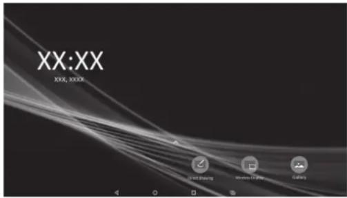
This is the home screen when the input mode is APPLICATION.
For information on APPLICATION mode, see the Software Guide.
- Be sure to set the date and time.
TIPS
- When "Select a Home app" screen appears, select "SHARP IWB Launcher", and select "ALWAYS".
• The clock is maintained by the internal battery. - If you already set the time but the date/time setting screen appears when the power is turned on, the internal battery may be exhausted. After replacing the internal battery, set the date and time.
- Please contact an authorized SHARP servicing dealer or service center for assistance with internal battery replacement.
• Estimated service life of the internal battery: About 5 years (depending on monitor operation) - The initial battery was inserted at the factory when the monitor was shipped, so it may run out of power before its expected operation life.
Touch Pen
To use the supplied touch pen in Windows, Touch pen Management Tool must be installed on the computer from the supplied CD-ROM.
To install the software, see the Touch pen Management Tool Operation Manual.
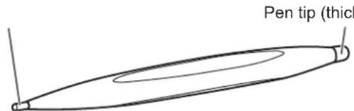
The following software recognizes the side of the touch pen that is touching the screen, enabling the two sides to be used as different pens.
- Pen Software
• Direct Drawing for Android
For details on how to install Pen Software and use the touch pen in the Pen Software, refer to the Pen Software Operation Manual.
For details on how to use the touch pen in Direct Drawing for Android, refer to the Software Guide.
Touch action
Touch action
Touch actions that can be used with this monitor differ according to operating system and application. The functions of touch actions are also different. For details, check operating system Help and the application's support documentation.
| Touch action\Operating system | Windows 8.1 / 10 | Chrome OS |
| Single-tap Yes Yes | ||
| Double-tap Yes Yes | ||
| Swipe Yes Yes | ||
| Swipe from edge of screen | Yes Yes | |
| Drag-and-drop Yes Yes | ||
| Flicks Yes Yes | ||
| Press-and-hold Yes Yes | ||
| Slide to pan Yes Yes | ||
| Zoom Yes Yes | ||
| Press-and-tap No Yes | ||
| Rotate Yes Yes |
TIPS
- On the Mac, the actions are the equivalent mouse actions.
- For the procedures for using the touch pen in the Pen Software, see the Pen Software Operation Manual.
■Common finger and touch pen actions
Single-tap
Same action as left-clicking a mouse. Touch with your finger/touch pen.

natural_image
Line drawing of a human hand making a peace sign with a small lightbulb above the index finger (no text or symbols)Double-tap
Same action as double-clicking a mouse. Quickly touch twice with your finger/touch pen.
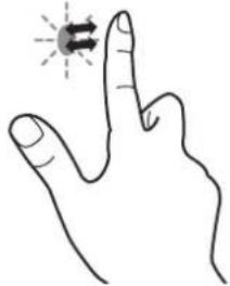
natural_image
Line drawing of a hand making a peace sign with a finger (no text or symbols)When double-tapping with your finger, be sure to lift your finger sufficiently off the screen after the first tap. If there is insufficient distance between the screen and your finger, double-tap will not take place.
Swipe
Touch the screen with your finger/touch pen, move without lifting, and then stop.

natural_image
Hand gesture pointing upward with a downward arrow (no text or symbols)Swipe from edge of screen
After touching the edge of the monitor with your finger/touch pen, move horizontally without releasing your finger/touch pen and then stop.

natural_image
Line drawing of a hand pointing upward with a finger, no text or symbols presentDrag-and-drop
Same action as drag-and-drop with a mouse.
Touch the screen with your finger/touch pen and move without lifting. When you have finished the movement, lift your finger/touch pen.

natural_image
Illustration of two hands demonstrating a curved motion with directional arrows (no text or symbols)Flicks
Flick your finger/touch pen in the direction of the function you want to use.

Press-and-hold
Same action as right-clicking a mouse.
Press briefly with your finger/touch pen, and then lift your finger/touch pen from the screen.

natural_image
Line drawing of a hand making a finger gesture with an arrow indicating the thumb area (no text or symbols present)Slide to pan
With your finger/touch pen touching the screen, move it up and down to scroll the screen.

natural_image
Line drawing of a hand with finger index finger and finger pointing downward (no text or symbols)■Finger actions
Zoom
Use in a screen that is capable of enlargement/reduction. Touch the screen with two fingers and move your fingers closer together to reduce the view, or apart to enlarge the view.

natural_image
Illustration of two fingers with finger tips and finger joints, showing finger movement direction (no text or symbols)Reduction

Enlargement
Press-and-tap
Same action as right-clicking a mouse.
With one finger touching the screen, tap once (single tap) with another finger.
Tap once (single tap) with another finger
With one finger touching

Touch action
Rotate
Use this action in a screen that is capable of image rotation. Touch the center point of the rotation with one finger. While holding that finger still, move another finger in the desired direction of rotation.
Move another finger in the desired direction of rotation
With one finger touching

TIPS
- The screen may not respond correctly in the following cases:
- Touch gesture is too quick.
- The distance between the two points is too short.
- The two points intersect.
Other functions
In Windows 8.1/10, input panel functions can be used.
For details, see Windows Help.
Input panel :
A software keyboard and an input panel with handwriting recognition appear on the screen.
In Windows 8.1/10, the ink function of Microsoft Office can be used.
Handwritten comments can be written, and handwriting can be recognized.
For details, see Microsoft Office Help.
Cautionary points
- Do not use the touch pen for any purpose other than touch panel operation.
- Do not press hard on the pen tip.
- Operation will not take place correctly if there is an obstacle between the infrared transmitter/receiver and the touch pen or your finger. Operation will not take place correctly if your fingers or your sleeve is near the screen.
- If the touch pen is held too flat against the screen, the touch position may not be correctly detected.
- If the touch pen does not work at the edge of the screen, move it slowly.
- This may not operate correctly if there is an inverter fluorescent light nearby.
- If there is dirt or foreign matter on the tip of the touch pen, remove it. Foreign matter may damage the screen.
- The touch pen position may occasionally deviate in the login screen. In this case, use the keyboard or mouse.
- If the USB cable becomes disconnected, the touch panel may not operate correctly after the USB cable is reconnected. In this case, restart the computer.
- When removing the pen tip or your finger from the screen, remove a sufficient distance. If the distance is not sufficient, a touch may be detected even if the screen is not touched.
Eraser
The eraser is used with the Pen Software and Direct Drawing for Android.
For details on how to use the eraser in Pen Software, see the Pen Software Operation Manual.
For details on how to use the eraser in Direct Drawing for Android, see the Software Guide.
!Caution
- When using the eraser, gently bring the cloth side into contact with the screen. Touching the screen with one of the non-cloth sides will damage the screen.
- If there is any dirt or foreign matter on the surface that contacts the screen, remove it. Foreign matter may damage the screen.
Basic Operation
Using the touch menu
You can touch the screen to change input mode, volume, and other settings.
- Press the TOUCH MENU button.
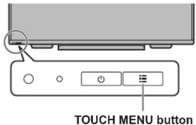
- Touch the screen to change settings.

(1) Input mode selection
Changes the input mode.
In APPLICATION mode, you can use Android applications. For details of APPLICATION mode, see the Software Guide.
* You can change the input mode by pressing the INPUT button on the remote control unit.
| Input mode Video | Audio | |
| APPLICATION APPLICATION | APPLICATION | |
| DisplayPort Display | Port input terminal | *2 |
| HDMI1 HDMI1 input | terminal | |
| HDMI2 HDMI2 input | terminal | |
| D-SUB D-sub input | terminal | Audio input terminal |
| OPTION*1 | Expansion slot | *2 |
- When the input mode is changed, the touch panel connection also changes. You can set whether the TOUCH PANEL1 terminal or TOUCH PANEL2 terminal is used in each input mode. (See page 35.)
*1 This is displayed when you have used the expansion slot to expand the functions.
*2 Select the terminal for AUDIO SELECT which is used for audio input. (See page 35.)
(2) Volume adjustment
Adjusts the volume.

Touch again to return the sound to the original volume.
(3) Settings
Adjust video and configure settings for quad-screen, touch operation, and other items. (See page 30.)
(4) Backlight off
Turn off the backlight.
When off, the backlight turns on when you press any button on the monitor or remote control unit.
(5) FREEZE
Freezes the video shown on the monitor.
To cancel, press any button other than the POWER button, MUTE button or VOLUME button.
Freeze is also canceled when the input signal changes (switching to no signal, changing the resolution, etc.).
In some cases a residual image may occur. Do not freeze the video for a long time.
(6) QUAD-SCREEN ON
You can display 4 screens at once. (See page 39.)
When quad-screen is displayed, the icon changes to the QUAD-SCREEN OFF icon (1).
(7) RECONFIGURE QUAD-SCREEN
The 4 screens set in SETTING INITIAL SCREEN (see page 37) are displayed.
(8) Exit touch menu
Closes the touch menu.
TIPS
- The touch menu can also be used with the remote control unit.
(1) Hold down the INFORMATION button at least 5 seconds.
The touch menu appears.
(2) Select the setting item with the ◀ or ▶ button.
(3) Set with the ▲ or ▼ button, and press the ENTER button.
- The setting is entered.
- Press the RETURN button to exit the touch menu.
Using the remote control unit

1. HDMI
Switch the input mode to HDMI1 or HDMI2.
2. Numeric input buttons
0 to 9 are also used in conjunction with the ID SET button.
3. MUTE
Turns off the volume temporarily.
Press the MUTE button again to turn the sound back to the previous level.
4. MODE (Color mode selection)
Each time you press this button, the color mode changes in the following order:
STD (Standard) → VIVID → sRGB → HIGH ILLUMINANCE → STD...
- HIGH ILLUMINANCE is a display with colors suited to bright locations.
- sRGB is international standard of color representation specified by IEC (International Electrotechnical Commission). Color conversion is made in taking account of liquid crystal's characteristics and represents color tone close to its original image.
5. VOLUME +/- (Volume adjustment)
Pressing + or - displays the VOLUME menu.

Press + or - to adjust the volume.
* If you do not press any buttons for about 4 seconds, the VOLUME menu automatically disappears.
6. INFORMATION
Displays monitor information.
![INFORMATION1 01/01/2019 TUE 12:00:00 AM INPUT MODE : HDMI1 SIZE : WIDE COLOR MODE : STD BRIGHT : 31 VOLUME : 15 REMOTE No. : 0 MODEL : PN-L751H VERSION : X.X.X.X S/N : XXXXXXXX STATUS : 0000-000000-00-0000 TOUCH PANEL : OK END:[RETURN]NE 3840x2160 V: 30 Hz H: 67.5 kHz](/content/2026/05/820587/images/2b1f3460cf16abee1eed5940edb7410990ace5d1c383e9742d01b2d78f55ae0f.jpg)
![INFORMATION2-1 01/01/2019 TUE 12:00:00 AM APPLICATION VERSION :X.X.XX MONITOR CONTROL SELECT :LAN Ethernet :ON IPv4 IP address :192.168.150. 2 IPv4 IP settings :DHCP MAC address :XX-XX-XX-XX-XX-XX Wireless LAN :ON IPv4 IP address :XXX.XXX.XXX.XXX IPv4 IP settings :DHCP MAC address :XX-XX-XX-XX-XX-XX END:[RETURN]NE 3 8 4 0 x 2 1 6 0 V: 30 Hz H: 67.5 kHz](/content/2026/05/820587/images/a5e3f604573491a8a49a16c629104e6595de0563b5f5e2be6183d60544e04017.jpg)
The display changes from INFORMATION1 → INFORMATION2-1 → INFORMATION2-2 → INFORMATION3 → clear display, and so on every time you press this button. When displaying INFORMATION, the display changes from INFORMATION1 → INFORMATION2-1 → INFORMATION2-2 → INFORMATION3 → INFORMATION1, and so on every time you press the ▶ button.
Pressing the RETURN button disappears the display.
• INFORMATION3 shows the information when you have used the expansion slot to expand the functions.
- The display disappears automatically after about 15 seconds.
7. FUNCTION
Use this to display the FUNCTION menu. (See page 43.)
8. ENTER
Confirms the setting.
9. FREEZE
Freezes the video shown on the monitor.
To cancel, press any button other than the POWER button, MUTE button or VOLUME button.
Freeze is also canceled when the input signal changes (switching to no signal, changing the resolution, etc.).
In some cases a residual image may occur. Do not freeze the video for a long time.
10. Buttons for operating the HDMI-connected device
When HDMI CEC LINK is set to AUTO, you can operate devices that support HDMI CEC in modes other than APPLICATION mode.
11. ID SET
Set a number on the remote control unit. (See page 41.)
12. OPTION
Switch the input mode to APPLICATION.
When using the expansion slot to expand the functions, input mode change alternately between APPLICATION and OPTION.
14. SIZE (Screen size selection)
The menu is displayed.
Press the ▲ or ▼button to select the screen size. (See page 28.)
15. PIP/PbyP
The menu is displayed.
Press the ▲ or ▼button to select PIP MODES/
QUAD-SCREEN MODE. (See page 39.)
16. BRIGHT +/- (Brightness adjustment)
Pressing + or - displays the BRIGHT menu.
BRIGHT 15
Press + or - to adjust the brightness.
* If you do not press any buttons for about 4 seconds, the BRIGHT menu automatically disappears.
17. INPUT (Input mode selection)
The menu is displayed.
Press the ▲ or ▼ button to select the input mode, and press the ENTER button to enter.
* For the input modes that can be selected, see "Using the touch menu" (see page 25).
18. MENU
Displays and turns off the menu screen. (See page 29.)
19. Cursor
These buttons are used to perform operations such as selecting items, changing adjustment values, and moving the cursor.
20. RETURN
Returns to the previous screen.
■Switching the screen size
Even when the screen size is changed, the display may remain the same depending on the input signal.
WIDE Displays image so it fills the entire screen.  | |
| ZOOM | The image is enlarged to fill the entire screen without changing the aspect ratio. The edges of the image may be cut off. |
| NORMAL | Displays the image so it fills the screen without changing the aspect ratio. |
| Dot by Dot | Displays the dots of the input signals as the corresponding dots on the screen. |
TIPS
- Using this monitor's screen-size switching function to compress or expand the screen for commercial or public viewing in establishments like cafes or hotels may infringe on the rights of the creators, as protected by Copyright Law, so please be careful.
- When dual-screen or quad-screen display is selected, the screen size cannot be changed.
- The appearance of the original video may change if you select a screen size with a different aspect ratio than the original image (e.g. TV broadcast or video input from external equipment).
- When 4:3 video is viewed with the whole screen using the screen-size switching function of this monitor, the edge of the video may be lost or appear distorted. If you wish to respect the creator's intentions, set the screen size to NORMAL.
- When playing commercial software, parts of the image (like subtitles) may be cropped. In this case select the optimal screen size using the screen-size switching function of this monitor. With some software, there may be noise or distortion at the edges of the screen. This is due to the characteristics of the software, and is not a malfunction.
• Depending on the original video size, black bands may remain at the edges of the screen.
Menu Items
Displaying the menu screen
Video and audio adjustment and settings of various functions are enabled. This section describes how to use the menu items. See page 31 for details of each menu items.
! Caution
- Do not turn the main power switch off while the menu items are being displayed. Doing so may initialize the settings.
TIPS
- Also check the time setting, network settings, and other settings in the Software Guide.
■Example of operation
(Adjusting CONTRAST in the PICTURE menu)
- Press the MENU button to display the menu screen.
![SCREEN SCREEN D-SUB PICTURE AUDIO SETUP MONITOR MULTIPIP OTHERS AUTO CLOCK 600 PHASE 25 H-POS 610 V-POS 37 RESOLUTION SETTING ⇒ INPUT SIGNAL ⇒ RESET ⇒ OK:[ENTER] END:[RETURN] 1920x1080 V: 60 Hz H: 67.5 kHz](/content/2026/05/820587/images/671431e7bf138078b2bed8aee2b1bafeda5fda784d9c3b59b33c4dacfd1a6206.jpg)
- Press the ▲ or Button to select PICTURE, and press the ENTER button.
- Press the ▲ or ▼ button to select CONTRAST.
![SCREEN PICTURE BRIGHT 31 CONTRAST 30 BLACK LEVEL 30 TINT 30 COLORS 30 SHARPNESS 12 COLOR ADJUSTMENT → ADVANCED → RESET → < D-SUB > MOVE OSD:[INFORMATION] BACK:[RETURN] 1920x1080 V: 60 Hz H: 67.5 kHz](/content/2026/05/820587/images/89dfa54d8987c4d3be4103bd53a08c00cbcb7eb9cfeb6e0fd8cfb4f117aa210e.jpg)
- Press the ◀ or button to adjust the setting.
![SCREEN PICTURE BRIGHT 31 CONTRAST 40 BLACK LEVEL 30 TINT 30 COLORS 30 SHARPNESS 12 COLOR ADJUSTMENT ⇒ ADVANCED ⇒ RESET ⇒ 〈D-SUB〉 AUDIO SETUP MONITOR MULTI/PIP OTHERS BACK:[RETURN]M 1920x1080 V: 60 Hz H: 67.5 kHz](/content/2026/05/820587/images/a51c3e71014313214925bb5c9a72e7619ef3feb072172a33658677a348cf21d0.jpg)
For items that have ➕, press the ENTER button to display the sub menu.
- Press the MENU button to close the menu screen.
TIPS
• The menu will differ depending on the input mode.
- The menu screen will close automatically if no operation is performed for about 15 seconds. (SCHEDULE screen will close in about 4 minutes.)
■Menu screen display
![SCREEN PICTURE BRIGHT 31 CONTRAST 30 BLACK LEVEL 30 TINT 30 COLORS 30 SHARPNESS 12 COLOR ADJUSTMENT ⇒ ADVANCED ⇒ RESET ⇒ Φ-SUB > BACK:[RETURN]M 1920 x 1080 V: 60 Hz H: 67.5 kHz AUDIO SETUP MONITOR MULTI/PIP OTHERS](/content/2026/05/820587/images/243863b86eb894c7dfe64e1ee7d4c5e028f42260c449c5f9d290e635100dcdaa.jpg)
1 Name of the menu
2 Input mode
3 An item being selected (highlighted)
4 Screen resolution of input signal, and other data.
TIPS
- Items that cannot be selected appear in gray. (e.g. Function not supported by the current input signal)
Configuring settings in the touch menu
You can configure the following settings from the touch menu. You can configure the settings by touch operation.
| PICTURE BRIGHT page | 32 | |
| CONTRAST | ||
| BLACK LEVEL | ||
| COLOR MODE | ||
| CONFIGURE QUAD-SCREEN | SETTING INITIAL SCREEN | page 37 |
| PRIORITY: AUTO INPUT SEL. | ||
| SAVE LAST INPUT CONFIG. | ||
| TARGET: SOUND / INPUT SEL. | ||
| OTHERS PORTRAIT/ | LANDSCAPE INSTALL | page 36 |
| LANGUAGE page 34 | ||
| TOUCH INPUT SELECT page 35 | ||
| TOUCH OUTPUT INVALID DISP. | page 36 | |
| TOUCH PANEL MODE | ||
| TOUCH OPERATION See right | ||
■Example of operation
(Adjusting CONTRAST in the PICTURE menu)
- Press the TOUCH MENU button.

- Touch the Settings icon
- Touch the PICTURE tab.


natural_image
Row of eight black square icons with white symbols on a gray background, no text or labels present.- Touch the ◀icon in CONTRAST to adjust the setting.
For items that show the >> icon, configure the setting in the menu that appears after you touch the >> icon, and then touch the BACK icon. - Touch the Exit touch menu icon ✗).
TOUCH OPERATION
Use this setting to enable or disable touch action.
TIPS
- When the input mode is changed, the disable touch action setting is canceled.
- When TOUCH OUTPUT INVALID ICON is set to ON and touch action is disabled, the TOUCH OUTPUT INVALID icon appears in the screen.

- You can touch the TOUCH OUTPUT INVALID icon in the screen to enable touch action.
- The position of the TOUCH OUTPUT INVALID icon can be changed. (See page 36.)
- The TOUCH OUTPUT INVALID icon appears even when a USB cable is not connected.
- In quad-screen display or when a color pattern is displayed, the TOUCH OUTPUT INVALID icon does not appear.
Menu item details
The menu will differ depending on the input mode.
■SCREEN
You can move the menu screen display position each time the INFORMATION button is pressed.
AUTO (D-SUB)
The CLOCK, PHASE, H-POS, and V-POS are automatically adjusted.
Pressing the ENTER button performs adjustment. Use this automatic adjustment when you use the D-SUB to display a computer screen for the first time or when you change the setting of the computer. (See page 42.)
CLOCK (D-SUB)
Adjusts frequency for sampling clock for applicable video.
Adjust when there is flickering in the form of vertical stripes.
When using the adjustment pattern (see page 42), make adjustments so that no vertical stripe noise appears in it.
PHASE (D-SUB)
Adjusts sampling clock phase for applicable video. Useful when small characters appear with low contrast and/or there are flickers at corners. When using the adjustment pattern (see page 42), make adjustments so that no horizontal stripe noise appears in it.
* Adjustments to PHASE should be made only after CLOCK has been correctly set.
H-POS (D-SUB)
Adjust the horizontal position of the image.
V-POS (D-SUB)
Adjust the vertical position of the image.
RESOLUTION SETTING (D-SUB)
H-RESOLUTION
Sets proper horizontal resolution when the resolution of input signals is not recognized properly.
(Adjustment may be impossible with some signals.)
V-RESOLUTION
Sets proper vertical resolution when the resolution of input signals is not recognized properly.
(Adjustment may be impossible with some signals.)
INPUT SIGNAL (D-SUB)
If the resolution of the computer is one of the following, make a selection from the following options.
480 LINES ...... AUTO, 640x480 or 848x480
768 LINES ....AUTO, 1024x768, 1280x768 or 1360x768
1050 LINES .....1400x1050 or 1680x1050
RESET
Resets the values of the SCREEN menu items to the factory default settings.
Select ON and then press the ENTER button.
Menu Items
■PICTURE
You can move the menu screen display position each time the INFORMATION button is pressed.
BRIGHT
Adjusts the backlight brightness.
CONTRAST
Adjusts the difference between the bright and dark portions of the image.
BLACK LEVEL
Adjusts the entire brightness of the video signals.
TINT
Adjusts the hue. Selecting + changes the color towards green, and selecting - changes it towards magenta.
COLORS
Adjusts the color intensity.
SHARPNESS
Adjusts the sharpness of the image.
COLOR ADJUSTMENT
COLOR MODE
Changes the color mode on the screen. The color mode on the screen can also be changed using a remote control unit. (See page 26 for details.)
WHITE BALANCE
THRU ......Displays the input signal level as is.
PRESET......Selects the color temperature using PRESET.
USER ....Adjusts R-/G-/B-CONTRAST and R-/G-/B-OFFSET respectively using USER.
PRESET
Selects the color temperature when the WHITE BALANCE is set to PRESET.
The setting values are shown for reference. The color temperature of the screen varies over time. This function is not intended to keep the color temperature constant.
USER
Adjusts each item when the WHITE BALANCE is set to USER.
R-CONTRAST....Adjusts bright-toned red component.
G-CONTRAST ... Adjusts bright-toned green component.
B-CONTRAST ....Adjusts bright-toned blue component.
R-OFFSET ...... Adjusts dark-toned red component.
G-OFFSET ......Adjusts dark-toned green component.
B-OFFSET ...... Adjusts dark-toned blue component.
COPY TO USER
Copies the value of white set for PRESET to the USER setting.
Select ON and then press the ENTER button.
(In the case other than white, color tone may differ from the PRESET.)
GAMMA
Selects the gamma.
C.M.S.-HUE
Adjusts color tone with 6 colors of R (red), Y (yellow), G (green), C (cyan), B (blue), and M (magenta).
C.M.S.-SATURATION
Adjusts color vividness with 6 colors of R (red), Y (yellow), G (green), C (cyan), B (blue), and M (magenta).
ADVANCED
AUTO (D-SUB)
The ANALOG GAIN and ANALOG OFFSET are automatically adjusted.
Pressing the ENTER button performs adjustment.
ANALOG GAIN (D-SUB)
Adjusts the bright portions of the video input signal.
ANALOG OFFSET (D-SUB)
Adjusts the dark portions of the video input signal.
NR
Reduce the image noise.
Setting a higher level reduces more noise. However, it may cause blurring on an image.
RGB INPUT RANGE
Sets the RGB input signal range.
When using HDMI, DisplayPort or OPTION set to AUTO, the RGB input signal range is detected automatically. Use AUTO normally.
If the RGB input signal range cannot be set appropriately even when using AUTO, set according to the image. When the setting is different, images will be displayed with washed out blacks and compressed gradients.
DISPLAY COLOR PATTERN
Displays a color pattern. Can be displayed while the menu screen is displayed, so you can refer to the pattern while adjusting the image. When WHITE, RED, GREEN, or BLUE is displayed, you can set the level in the range of 0 to 255.
OFF......No pattern display.
WHITE......White single color pattern display.
RED......Red single color pattern display.
GREEN ......Green single color pattern display.
BLUE......Blue single color pattern display.
USER....Red/green/blue mixed color pattern display. When USER is selected, set each color's level.
HDR (HDMI)
To play content that supports HDR, select ON and set HDMI MODES to MODE1.
If HDMI MODES is set to MODE2, content that supports HDR cannot be played.
To make the setting effective, you must restart this monitor.
RESET
Resets the values of the PICTURE menu items to the factory default settings.
Select ON and then press the ENTER button.
AUDIO
TREBLE
Adjusts the volume of treble-level sound.
BASS
Adjusts the volume of bass-level sound.
BALANCE
Adjusts the balance of the audio sound between right and left.
RESET
Resets the values of the AUDIO menu items to the factory default settings.
Select ON and then press the ENTER button.
SETUP
DATE/TIME SETTING
Display the date and time.
When select SET, input mode change to APPLICATION, and you can set the date and time.
When APPLICATION is set to DISABLE, SET does not appear. Set in the displayed screen.
TIME FORMAT (when APPLICATION is ENABLE)
Set the time display format.
Select the display format, and select SET.
DATE/TIME FORMAT (when APPLICATION is DISABLE)
Set the date/time display format.
SCHEDULE (See page 40.)
You can turn the power on/off and change the screen brightness at a specified time.
LANGUAGE
Set the display language for the menu screen.
INPUT SELECT
DisplayPort STREAM
Set how DisplayPort is used.
If a device that do not support DisplayPort1.2 is connected, set to SST1.
SST1 ....Use as single stream (DisplayPort1.1).
SST2 ....Use as single stream (DisplayPort1.2).
HDMI MODES
HDMI MODES settings change how the content displayed is processed and decoded using the HDMI input terminal or expansion slot (when you have used the expansion slot to expand the function).
MODE1 ..... Normally used.
This will support most common color spaces and other encoding signals.
MODE2 ..... This should be used for YCbCr 4:2:0 at 4K Vsync 50/60 Hz signals.
Also use this when a non 4K input signal does not display correctly in MODE1.
CEC SETTING
HDMI CEC LINK
AUTO ...... HDMI CEC function is used.
If the device connected to the HDMI input terminal supports CEC, the input mode of the monitor changes to HDMI when playback starts on the device.
OFF......HDMI CEC function is not used.
AUTO POWER ON
This can be set when HDMI CEC LINK is set to AUTO.
If the device connected to the HDMI input terminal supports CEC, you can specify whether or not the monitor power turns on when the device power is turned on.
INPUT MODE NAME
For each terminal, you can change the input mode name that is displayed during input mode selection or display. The names of INPUT1 to INPUT6* can be changed. (*Factory default.)
(1) Select the input mode name (INPUT1 to INPUT6) that you want to change, and press the ENTER button.
f the input mode name can be changed, "EDIT: [ENTER]" will appear.
(2) Move the cursor to the character that you want to change with the ◀ or ▶ button, and change the character with the ▲ or ▼ button.
Change the character type with the MODE button (upper case alphabet, lower case alphabet, numbers, symbols).
(3) When you have finished the change, press the ENTER button.
Up to 18 characters can be used.
AUDIO SELECT
Selects the terminal used to input audio signals in each input mode.
AUDIO OPTION
SPEAKER SELECT
Selects the speaker to be used.
AUDIO OUTPUT
Sets the volume of sound output from the audio output terminal.
VARIABLE1...... You can adjust the volume from the speakers of this monitor and the audio output terminal simultaneously by using VOLUME.
VARIABLE2...... You can adjust the volume from the audio output terminal by using VOLUME.
Sound will not be output from the speakers of this monitor.
FIXED...... Fixes the volume from the audio output terminal. Adjust the volume by using an external device.
AUDIO INPUT LEVEL
Selects the maximum audio input level of the audio input terminal.
MONAURAL AUDIO
Outputs audio signals as monaural.
TOUCH INPUT SELECT
Set the TOUCH PANEL terminal connected to the computer in each input mode.
When “-” is selected, the touch panel cannot be used.
START INPUT MODE
You can set the input mode that will be in effect when the power is turned on.
When this is set to LAST INPUT MODE, the input mode when the power was last turned off will appear.
* When NO SIGNAL AUTO INPUT SEL. is ON and there is no input signal in the set input mode, the input mode will change to the input mode that has an input signal.
COMMUNICATION SETTING
MONITOR CONTROL SELECT (when APPLICATION is ENABLE)
RS-232C ...... Select to control this monitor by RS-232C.
LAN ...... Select to control this monitor by LAN.
APPLICATION.... Select to control from the application of APPLICATION mode.
BAUD RATE
Selects the communication speed used for RS-232C communication.
REMOTE No.
Sets the number of the remote control unit. (See page 41.)
Menu Items
■MONITOR
| PORTRAIT/LANDSCAPE INSTALL |
| LANDSCAPE......Landscape orientation |
| PORTRAIT ......Portrait orientation |
| BACKWARD TILT INSTALLATION |
| OFF ......Portrait/landscape installation. |
| ON ......Backward tilt installation. |
| OSD H-POSITION |
| Adjusts the horizontal display position of menu screen. |
| OSD V-POSITION |
| Adjusts the vertical display position of menu screen. |
| POWER SAVE MODE |
| When OFF is selected, startup time from standby mode is reduced. Note, however, that more power will be consumed in standby mode. Android continues to run in standby mode.When ON is selected, current consumption is reduced while the monitor is in standby mode. Android is also shut down. Note, however, that the startup time from standby mode becomes longer.If set to ON, certain RS-232C commands and LAN control cannot be used in standby mode. (See pages 45 and 53.) |
| OFF IF NO OPERATION |
| Determines whether or not to set the monitor to go into standby mode when there is no operation by the remote control unit, touch, RS-232C control or LAN control.When the setting is ON, set the time until standby mode is entered in TIME. |
| POWER ON DELAY |
| When ON is set, you can delay the screen display after the monitor is turned on.When ON is selected, set the delay time with INTERVAL (interval can be set up to 60 seconds in units of 1 second).When this function is activated, the power LED flashes (at approx. 0.5 second interval) in blue. |
| SELF ADJUST |
| On a D-SUB screen, specify whether to perform screen adjustment automatically or not.When ON is selected, the screen is automatically adjusted when its resolution is 800 x 600 or higher and the timing of input signals changes and other cases. “ADJUSTING” appears on the screen during the adjustment.If SELF ADJUST is set to ON, set the time it takes to start the SELF ADJUST function in START TIMING.For images with black edges, etc., depending on the signal, adjustment may not be possible. In this case select OFF. (Perform manual adjustment of the screen.) |
| TOUCH PANEL |
| TOUCH OUTPUT INVALID DISP.TOUCH OUTPUT INVALID ICON......Sets whether the TOUCH OUTPUT INVALID icon is displayed when touch action is disabled.CHANGE DISPLAY POSITION......Sets the display position of the TOUCH OUTPUT INVALID icon. |
| TOUCH PANEL MODEWhen the Vsync of the input signal is 60 Hz, setting this to ON improves touch panel tracking.When two screens are displayed, or when V-POS is adjusted on the SCREEN menu, the screen may become distorted.Some input signals may also cause screen distortion.If the screen becomes distorted, set to OFF. |
■MULTI/PIP
PIP/PbyP
PIP MODES
Sets the display method.
OFF ...... Displays one screen.
PIP ......Displays a sub screen inside a main screen.
PbyP......Displays a main screen and a sub screen in a line.
PbyP2.....Displays a main screen which measures 2560 pixels in the longest direction and a sub screen in a line.
PIP SIZE
Sets the size of the sub screen in PIP mode.
PIP H-POS
Adjusts the horizontal position of the sub screen in PIP mode.
PIP V-POS
Adjusts the vertical position of the sub screen in PIP mode.
PIP BLEND
In PIP mode, use this menu item to display the sub screen transparently.
PIP SOURCE
Selects the input signal of the sub screen in PIP, PbyP or PbyP2 mode.
SOUND CHANGE
Sets the sound which is output in PIP, PbyP or PbyP2 mode.
MAIN POS
Sets the position of the main screen in PbyP or PbyP2 mode.
PbyP2 POS
Sets the position of the sub screen in PbyP2 mode.
CONFIGURE QUAD-SCREEN
QUAD-SCREEN MODE
Set how the screens are displayed.
OFF ...... Display single screen.
ON......Display 4 screens simultaneously.
SETTING INITIAL SCREEN
Set the input mode displayed in each of the 4 screens.
When AUTO is selected, input modes that have input signals are displayed in the order set in PRIORITY: AUTO INPUT SEL..
PRIORITY: AUTO INPUT SEL.
Set the order of priority for the input mode that is displayed when AUTO is selected for SETTING INITIAL SCREEN.
The lower the number, the higher the priority.
SAVE LAST INPUT CONFIG.
OFF ...... When quad-screen display is started, the 4 screens set in SETTING INITIAL SCREEN always appear.
ON...... When quad-screen display is started, the previously displayed 4 screens appear.
TARGET: SOUND / INPUT SEL.
When quad-screen is displayed, you set the screen whose audio is output, and the screen whose input is changed.
When you return to single screen display, the input mode will return to the input mode set here.
RECONFIGURE QUAD-SCREEN
Displays 4 screens again according to SETTING INITIAL SCREEN setting.
This can be set when QUAD-SCREEN MODE is set to ON.
INPUT SIGNAL INFO.
This shows the input mode, resolution, and frequency of the displayed screens.
OTHERS
POWER MANAGEMENT
POWER MANAGEMENT determines whether or not to switch modes from no signal to the input signal waiting mode.
CONNECT AUTO INPUT SELECT
Sets whether the input into the input terminal automatically changes when a video signal is input into that terminal. The input via the expansion slot is ignored. (With some input signals, the input may not change.)
NO SIGNAL AUTO INPUT SEL.
Specify whether to change inputs automatically. When ON is selected and no signal is present in the selected input mode, the monitor automatically changes the selected mode to another mode where a video signal is present. When there are video signals in multiple input modes, switching takes place according to the order of priority set in AUTO INPUT SELECT PRIORITY.
AUTO INPUT SELECT PRIORITY
Sets the order of input terminal priority for NO SIGNAL AUTO INPUT SEL.. When an option that supports this function is connected to the expansion slot, you can set the order in OPTION. (If the option does not support this function, "OPTION" will not appear.) Input does not change automatically for terminals without a priority setting. The lower the number, the higher the priority.
LOGO SCREEN
Sets whether or not to display the logo screen.
VOLUME
Adjusts the volume.
MUTE AUDIO
Temporarily mutes the audio.
MUTE WITH FREEZE
Set whether or not audio turns off during freeze.
BACKLIGHT OFF
When set to ON, the backlight turns off. Audio does not turn off.
TIPS
- When WHITE BALANCE is set to THRU, BLACK LEVEL, CONTRAST, TINT, COLORS, GAMMA, C.M.S.-HUE, C.M.S.-SATURATION, and COPY TO USER cannot be set.
- If COLOR MODE is set to sRGB, the following items cannot be set. WHITE BALANCE, PRESET, USER, COPY TO USER, and GAMMA
- When the COLOR MODE is set to VIVID or HIGH ILLUMINANCE, GAMMA cannot be adjusted.
- When displaying the color pattern, it is possible to adjust certain items of the PICTURE menu. Non-adjustable items cannot be selected.
- When the input signal is HDR signal, GAMMA, COLOR MODE and BRIGHT cannot be adjusted.
■Dual-screen display
You can display two screens simultaneously.
Set this function with PIP MODES of PIP/PbyP in the MULTI/PIP menu.
Or, press the PIP/PbyP button, and select the mode.
| PIP |  | A sub screen is displayed inside a main screen. |
| PbyP |  | A main screen and a sub screen are displayed in a line. |
| PbyP2 |  | Displays a main screen which measures 2560 pixels in the longest direction and a sub screen in a line. |
* The currently selected input signal is displayed on the main screen.
* The following combination is not available for display.
HDMI1 - OPTION
TIPS
- You might infringe on a copyright of the author which is protected by copyright law when you display the images of the computer screen and television/VCR simultaneously for profit-making or to show the image to the public.
- The screen size for dual-screen display is the same as the screen size for single-screen display. The Dot by Dot screen is displayed in NORMAL size except when it is set as the PIP main screen.
- When dual-screen display is selected, the CONNECT AUTO INPUT SELECT function and NO SIGNAL AUTO INPUT SEL. function are disabled.
- When dual-screen display is selected, the AUDIO menu cannot be set.
- When dual-screen display is selected, the DISPLAY COLOR PATTERN cannot be set.
- When an interlaced signal (1080i, 480i, video) is input to the sub screen, horizontal lines may flicker. If this happens, display the image on the main screen.
- Touch operation cannot be used in the sub screen.
- When HDMI CEC LINK is set to AUTO, SOUND CHANGE on the PIP/PbyP may be changed to MAIN due to the switching of the monitor's input or due to the operation of the HDMI-connected device.
• The sub screen does not support HDR signals.
■Quad-screen display
You can display 4 screens simultaneously.
Landscape orientation Portrait orientation
| Position 1(1920×1080) | Position 2(1920×1080) |
| Position 3(1920×1080) | Position 4(1920×1080) |
| Position 2(1080×1920) | Position 4(1080×1920) |
| Position 1(1080×1920) | Position 3(1080×1920) |
Displaying 4 screens
- Press the TOUCH MENU button, and touch the QUAD-
SCREEN ON icon (4).
Or, set CONFIGURE QUAD-SCREEN - QUAD-SCREEN MODE to ON in the MULTI/PIP menu.
Or, press the PIP/PbyP button, and select the QUADSCREEN.
• The 4 screens set in SETTING INITIAL SCREEN appear.
- When SAVE LAST INPUT CONFIG. is ON, the previously displayed 4 screens appear.
- You can return to the 4 screens set in SETTING INITIAL SCREEN using the RECONFIGURE QUAD-SCREEN icon (☐) in the touch menu, or CONFIGURE QUAD-SCREEN – RECONFIGURE QUAD-SCREEN in the MULTI/PIP menu.
Deciding the screen that will be the audio output/input mode selection target
Set the screen whose audio is output, and the screen whose input is changed.
- Double-tap the screen you want to be the target. Or, set in CONFIGURE QUAD-SCREEN - TARGET: SOUND / INPUT SEL. in the MULTI/PIP menu.
Returning to single screen
- Press the TOUCH MENU button, and touch the QUAD-
- The screen set in the audio output/input mode selection target is displayed on 1 screen.
TIPS
- You might infringe on a copyright of the author which is protected by copyright law when you display the images of the computer screen and television/VCR simultaneously for profit-making or to show the image to the public.
- When quad-screen display is selected, screen size cannot be changed.
The screen size for quad-screen display is the same as the screen size for single-screen display. The Dot by Dot screen is displayed in NORMAL size. - When quad-screen display is selected, the CONNECT AUTO INPUT SELECT function and NO SIGNAL AUTO INPUT SEL. function are disabled.
- When quad-screen display is selected, SCREEN menu and AUDIO menu cannot be set.
- When quad-screen display is selected, the DISPLAY COLOR PATTERN cannot be set.
- When quad-screen display is selected, the monitor will not enter the input signal waiting mode even if POWER MANAGEMENT is set to ON.
- When quad-screen display is selected, HDMI CEC LINK does not operate.
- When quad-screen display is selected, the FREEZE, DP (DisplayPort), HDMI, and OPTION buttons cannot be used.
- When quad-screen display is selected, the position 1 screen is output from the DisplayPort output terminal.
- Positions 2 to 4 do not support HDR signals.
- When quad-screen display is selected, the connected computer cannot be operated by touch.
■SCHEDULE
You can set the time to switch the monitor on and off. Set this function with SCHEDULE in the SETUP menu. (See page 34.)
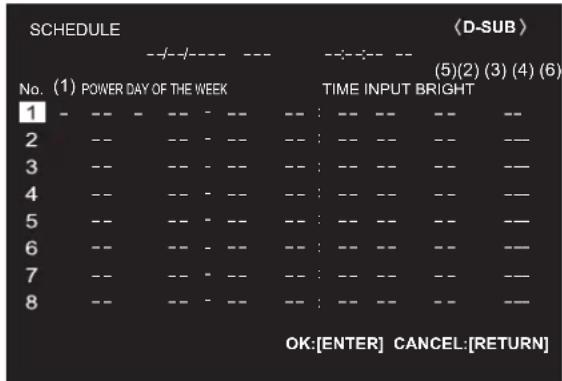
other
| No. | POWER DAY OF THE WEEK | TIME INPUT BRIGHT | OK: [ENTER] CANCEL: [RETURN] | |---|---|---|---| | 1 | -- | -- : -- | --- | | 2 | -- | -- : -- | --- | | 3 | -- | -- : -- | --- | | 4 | -- | -- : -- | --- | | 5 | -- | -- : -- | --- | | 6 | -- | -- : -- | --- | | 7 | -- | -- : -- | --- | | 8 | -- | -- : -- | --- |- Press the ▲ or ▼ button to select the SCHEDULE number, and press the ▶ button.
- Set the SCHEDULE. (See the description below.) Press the ◀ or ▶ button to select items, and press the ▲ or ▼ button to change the setting.
- Press the ENTER button. SCHEDULE becomes effective.
(1)
●: SCHEDULE effective
-: SCHEDULE not effective
(2) POWER
ON: Switches the monitor on at the specified time. OFF: Switches the monitor off at the specified time and puts the monitor in standby mode.
(3) DAY OF THE WEEK
Specifies the day of the week to execute the SCHEDULE.
0: ONLY ONCE Executes the SCHEDULE once on the specified day. Specify the day of the week to execute the SCHEDULE.
1: EVERY WEEK Executes the SCHEDULE on the specified day of the week every week. Specify the day of the week to execute the SCHEDULE. Periodic setting such as “Monday through Friday” is also possible.
2: EVERY DAY Executes the SCHEDULE every day regardless of the day of the week.
(4) TIME
Specifies the time to execute the SCHEDULE. Set the time on a 12-hour basis. (Factory default)
(5) INPUT
Specifies the input mode at power-on. If you don't specify this the input active at the last power-off will appear. When START INPUT MODE is set to a value other than LAST INPUT MODE, the input mode configured for START INPUT MODE will be set.
(6) BRIGHT
Sets the brightness when changing the screen brightness at a specified time.
! Caution
- Do not switch off the main power after setting the SCHEDULE.
- Specify the correct date and time. (See page 34.) SCHEDULE does not function unless the date and time are specified.
- Check regularly that the set date and time are correct.
- When a temperature abnormality occurs and the backlight brightness is reduced, the brightness is not changed even if a schedule set to BRIGHT is executed.
- When executing a power off schedule, a data save message will appear about once a minute starting about 5 minutes prior to power off. Save data you need. When the power turns off, the data will be lost.
TIPS
- Up to 8 SCHEDULE items can be registered.
- Setting the SCHEDULE flashes the power LED in orange in standby mode.
- A SCHEDULE that has a large number has precedence over that of a small number when schedules overlap.
■About remote control numbers
If there is another monitor nearby, you can change the remote control number to prevent the other monitor from being operated by the remote control unit.
Set the same number in the monitor and in the remote control unit.
TIPS
• You can set remote control numbers to values from 0 to 9.
- When the remote control unit batteries become exhausted and when you replace the batteries, the number on the remote control unit may be reset to 0.
Changing the remote control number on the monitor Use REMOTE No. on the SETUP menu to set the number. (See page 35.)
- Use the ◀ or ▶ button to select the remote control number.
- Select ON and press the ENTER button.
The remote control number is set on the monitor.
Changing the remote control number on the remote control unit
- While holding down the ID SET button, hold down the number that corresponds to the remote control number set on the monitor for 5 seconds or more, and then release these buttons.
The remote control number is set on the remote control unit.
Checking the remote controller number
- Press the INFORMATION button to display INFORMATION1.
- Check that REMOTE No. is the remote control number that you have set in the above procedure.
- Press the RETURN button to close the monitor INFORMATION screen.
TIPS
- If the remote control numbers on the monitor and remote control unit are different, they will both be displayed on INFORMATION1. On this screen, you can press the ENTER button to match the number on the monitor with the number on the remote control unit.
- Even if the remote control numbers are different, you can use the remote control unit to display the INFORMATION screen.
Adjustments for computer screen display
■Automatic adjustment
When you use the D-SUB to display a computer screen for the first time, or when you change the setting of the computer, use the automatic screen adjustment.
- Switch the input to D-SUB and display the adjustment pattern. (See the description below.)
- Press the MENU button and use the ▲ or ▼ button to display the SCREEN menu.
- Press the ENTER button and select "AUTO".
- Press the ENTER button.
The automatic adjustment is complete in several seconds.
- Press the MENU button to close the menu screen.
TIPS
- If the screen cannot be adjusted properly with one automatic adjustment, repeat the automatic adjustment two or three times. Try manual adjustment if necessary.
■Screen display for adjustment
Before making adjustments in the SCREEN menu or PICTURE menu, display an image to brighten the entire screen. If you are using a Windows computer, use the adjustment pattern on the supplied CD-ROM.
Opening the adjustment pattern
The following example is performed in Windows 10.
- Load the supplied CD-ROM into the computer's CD-ROM drive.
- Open [CD Drive] in [This PC].
- Double-click [Adj_uty.exe] in the [Monitor] folder.
The adjustment pattern will appear.
Adjust the screen automatically or manually.

natural_image
Pure electrical circuit lines without any symbols- When adjustment is finished, press the [Esc] on the computer's keyboard to quit the adjustment program.
- Eject the CD-ROM from the CD-ROM drive.
TIPS
- If the display mode on the computer you are using is 65000 colors, the color levels in the color pattern may appear differently or grayscale may appear to be colored. (This is due to the specifications of the input signal and is not a malfunction.)
Initialization (Reset)/Functional Restriction Setting (FUNCTION)
You can reset the settings to the factory default settings or restrict operations.
1. Press the FUNCTION button, and then press the MENU button within 10 seconds.
![FUNCTION ALL RESET ADJUSTMENT LOCK ADJUSTMENT LOCK TARGET RS-232C/LAN OSD DISPLAY LED TEMPERATURE ALERT STATUS ALERT POWER BUTTON EXTERNAL CONTROLLER INPUT SIGNAL RESPONSE LEVEL APPLICATION APPLICATION RECOVERY MODE UPDATE MAIN SOFTWARE OFF UNLOCKED ON 1 ON LED OFF MONITOR 1 OK:[ENTER] END:[RETURN]](/content/2026/05/820587/images/6c4216593e29877b2896f9c3d4198c580f6123da4b4ef4fbbe2bf043af2604bd.jpg)
2. Select and set the items.
ALL RESET
Resets the settings to the factory default settings.
Press the ENTER button, select the resetting method, and then press the ENTER button.
After initialization, turn the main power switch off and then back on.
ALL RESET 1:
Resets all the settings to the factory default settings. In APPLICATION mode, only the settings of the factory-installed applications are initialized.
ALL RESET 2:
Returns the settings to the factory default settings.
However, the following items are not returned: REMOTE No., MONITOR CONTROL SELECT, BAUD RATE, APPLICATION
(see pages 35 and 44.);
the applications of APPLICATION mode also are not returned.
ADJUSTMENT LOCK
You can disable operations on the monitor and the remote control unit that use buttons.
OFF ...Enables operation.
ON 1 ..Disables all operations other than turning power on/off and FUNCTION.
ON 2 .. Only the FUNCTION operation is enabled. Disables all operations other than FUNCTION (not even power on/off).
ADJUSTMENT LOCK TARGET
Sets the target to prohibit operation of with ADJUSTMENT LOCK.
REMOTE CONTROL.....Prohibits remote control operation
MONITOR BUTTONS ... Prohibits monitor button operation
BOTH....Prohibits remote control and monitor button operation
RS-232C/LAN
Specifies whether to allow control via RS-232C or LAN. (See pages 45 and 53.)
OSD DISPLAY
Shows/hides the menu, modes and messages. The FUNCTION screen cannot be hidden.
ON 1 ...... Shows all menus, modes and messages.
ON 2 ...... Hides messages automatically displayed by the display. Shows messages during operation.
OFF ...... Hides all menus, modes and messages.
LED
Specifies whether to light the power LED.
TEMPERATURE ALERT
Selects the notification method for an abnormal temperature.
OFF .... Do not notify about an abnormal temperature.
OSD & LED .... When an abnormal temperature is detected, the power LED flashes in orange and blue alternately and the screen displays a message: TEMPERATURE.
LED.... When an abnormal temperature is detected, the power LED flashes in orange and blue alternately.
STATUS ALERT
Selects the notification method for a hardware error. OFF ...... Do not notify about the error.
OSD & LED .... When a hardware error is detected, the power LED illuminates in blue and orange alternately and the screen displays a message: STATUS [xxxx].
LED...... When a hardware error is detected, the power LED illuminates in blue and orange alternately.
POWER BUTTON
Normally, leave this setting as MONITOR.
When using an optional part, if instruction appears, change the setting accordingly.
EXTERNAL CONTROLLER INPUT
Normally, you do not need to change this setting.
When using an optional part, if instruction appears, change the setting accordingly.
SIGNAL RESPONSE LEVEL
Normally, you do not need to change this setting. Use this option to set the level of response to signal changes.
APPLICATION
Set whether or not APPLICATION mode is used.
DISABLE ..... Do not use APPLICATION mode. The input mode cannot be changed to APPLICATION.
ENABLE ..... UseAPPLICATIONmode.
APPLICATION RECOVERY MODE
Before selecting this item, connect a commercially available USB keyboard to the USB port.
Select this item when you want to return to the factory default settings, such as when an application does not operate correctly.
Select ON, and select "Wipe data/factory reset".
Other items are not used.
* During processing, do not turn off the power.
UPDATE MAIN SOFTWARE
Not normally used.
Used by service technicians when performing repairs or otherwise.
3. Press the RETURN button to return to the normal screen.
TIPS
- When both abnormal temperature and hardware error are detected, the hardware error notification overrides.
- If TEMPERATURE ALERT or STATUS ALERT is set to OSD & LED, alert messages will appear even if the OSD DISPLAY is set to ON 2 or OFF.
- If TEMPERATURE ALERT or STATUS ALERT is set to LED or OSD & LED, the power LED lights even if the LED function is set to OFF.
Controlling the Monitor with a computer (RS-232C)
You can control this monitor from a computer via RS-232C (COM port) on the computer.
TIPS
- To control the monitor via RS-232C, set MONITOR CONTROL SELECT to RS-232C. (When this is done, control via LAN or application is not possible.)
Computer connection
Connect with RS-232 straight cable between the computer's COM port (RS-232C connector) and the RS-232C input terminal on the monitor.
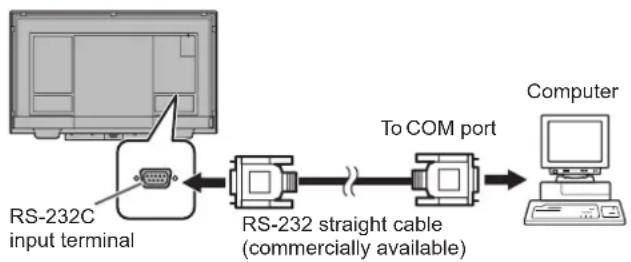
flowchart
graph LR
    A["RS-232C input terminal"] --> B["RS-232 straight cable (commercially available)"]
    B --> C["To COM port"]
    C --> D["Computer"]
Communication conditions
Set the RS-232C communication settings on the computer to match the monitor's communication settings as follows:
| Baud rate * | |
| Data length 8 bits Flow control | |
| Parity bit None | |
| Stop bit | 1 bit |
| None |
* Set to the same baud rate as the BAUD RATE setting of SETUP menu. (Initial setting: 38400 bps)
Communication procedure
■Command format
When a command is sent from the computer to the monitor, the monitor operates according to the received command and sends a response message to the computer.

Example: VOLM0030 VOLM _ 30
* Be sure to input 4 characters for the parameter. Pad with spaces (“_”) if necessary.
("☐" is a return code (0DH, 0AH or 0DH))
Wrong : VOLM30
Right : VOLM 30
When inputting a negative value, specify a numerical value in three digits.
Example: OFSR-127
When the parameter part is 5 or more characters, specify parameters using a specified number of characters without using spaces.
Example: MPOS010097
If a command has "R" listed for "Direction" in the "RS-232C command table" on page 47, the current value can be returned by using "?" as the parameter.
Example:
VOLM ? ? ? ? ←
From computer to monitor (How much is current volume setting?).
30
←
From monitor to computer (Current volume setting: 30).
■Response code format
When a command has been executed correctly

A response is returned after a command is executed.
When a command has not been executed

TIPS
- "ERR" is returned when there is no relevant command or when the command cannot be used in the current state of the monitor.
- If communication has not been established for reasons such as a bad connection between the computer and monitor, nothing is returned (not even ERR).
- "ERR" may be returned when a command cannot be received correctly due to interference from the surrounding environment. Please ensure that the system or software resends the command if this occurs.
If execution of the command is taking some time

When the following commands are used, "WAIT" is returned. In this case, a value will be returned if you wait a while. Do not send any command during this period.
- Commands which return WAIT:
RSET, POWR, INPS, ASNC, PXSL, AGIN, HDRS, DPST, HD1M, HD2M, OPTM, MWIN, MWIP, MWPP, MSCS, MSP1, MSP2, MSP3, MSP4, MSIP, BOMD, APST, APRV, WIDE
When control via RS-232C is locked (see page 43)

When MONITOR CONTROL SELECT is set to LAN or APPLICATION

■Communication interval
• After OK or ERR is returned, you must send the following commands.
To set a timeout for the command response, specify 10 seconds or longer.
- Provide an interval of 100 ms or more between the command response and the transmission of the next command.
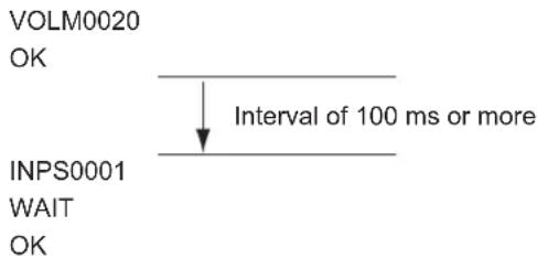
TIPS
- When executing ALL RESET, set the timeout period to 30 seconds or longer.
- When turning the power on while the POWER ON DELAY function is in use, set the timeout period to the POWER ON DELAY period + 10 seconds or longer.
RS-232C command table
How to read the command table
Command: Command field (See page 45.)
Direction: W When the "Parameter" is set in the parameter field (see page 45), the command functions as described under "Control/Response Contents".
R The returned value indicated under "Reply" can be obtained by setting "????", "(repeater control) in the parameter field. (See page 45.)
____?" or "???+"
Parameter: Parameter field (See page 45.)
Reply: Response (Returned value)
* : When POWER SAVE MODE is set to OFF:
“●/○”: Indicates a command which can be used in standby mode or when the power is on.
“”:Indicates a command which can be used when the power is on. Cannot be used in standby mode.
When POWER SAVE MODE is set to ON:
“●”:Indicates a command which can be used in standby mode or when the power is on.
“o/-”: Indicates a command which can be used when the power is on. Cannot be used in standby mode.
Power control/Input mode selection
| Function | Command | Direction | Parameter | Reply | Control/Response contents | * | |
| Power control | POWR | W | 0 | Switches to standby mode. | ● | ||
| 1 | Returns from standby mode. | ||||||
| R | 0 | Standby mode | |||||
| 1 | Normal mode | ||||||
| 2 | Input signal waiting mode | ||||||
| Input mode selection | INPS | W | 0 | Toggle change for input mode. | |||
| 2 | D-SUB | ||||||
| 10 | HDMI1 | ||||||
| 13 | HDMI2 | ||||||
| 14 | DisplayPort | ||||||
| 21 | OPTION"ERR" when nothing is attached in the expansion slot. | ||||||
| 24 | APPLICATION | ||||||
| R | 2 | D-SUB | |||||
| 10 | HDMI1 | ||||||
| 13 | HDMI2 | ||||||
| 14 | DisplayPort | ||||||
| 21 | OPTION | ||||||
| 24 | APPLICATION |
SCREEN menu
| Function | Command | Direction | Parameter | Reply | Control/Response contents | * | |
| AUTO | ASNC | W | 1 | When the input mode is D-SUB. | - | ||
| CLOCK | CLCK | WR | 0-1200 | 0-1200 | When the input mode is D-SUB. Varies depending on the signal. | ||
| PHASE | PHSE | WR | 0-63 | 0-63 | When the input mode is D-SUB. | ||
| POSITIONING P | POSITION OF THE LONGEST DIRECTION | HPOS | WR | 0-800 | 0-800 | When the input mode is D-SUB. Varies depending on the signal. | |
| POSITION OF THE SHORTEST DIRECTION | VPOS | WR | 0-200 | 0-200 | When the input mode is D-SUB. Varies depending on the signal. | ||
| RESOLUTION SETTING | LONGEST DIRECTION RESOLUTION | HRES | WR | 300-1920 | 300-1920 | When the input mode is D-SUB. Only even numbers are valid for parameters. Varies depending on the signal. | |
| SHORTEST DIRECTION RESOLUTION | VRES | WR | 300-1200 | 300-1200 | |||
| INPUT SIGNAL (D-SUB) | PXSL | WR | 1 | 1 | 768) 1360 x 768 | ||
| 2 | 2 | 768) 1280 x 768 | |||||
| 3 | 3 | 768) 1024 x 768 | |||||
| 5 | 5 | 480) 848 x 480 | |||||
| 6 | 6 | 480) 640 x 480 | |||||
| 7 | 7 | 1050) 1680 x 1050 | |||||
| 8 | 8 | 1050) 1400 x 1050 | |||||
| 9 | 9 | 768) AUTO | |||||
| 10 | 10 | 480) AUTO | |||||
| Check the resolution | PXCK | R | - | Returns current resolution in the form of hhh, vvv. | |||
| RESET | ARST | W | 1 | ||||
PICTURE menu
| Function | Command | Direction | Parameter | Reply Control/Response contents * | |||
| BRIGHT VLMP WR 0-31 0-31 | |||||||
| CONTRAST CONT WR 0-60 0-60 | |||||||
| BLACK LEVEL BLVL WR 0-60 0-60 | |||||||
| TINT TINT WR 0-60 0-60 | |||||||
| COLORS COLR WR 0-60 0-60 | |||||||
| SHARPNESS | SHRP | WR 0-24 | 0-24 | ||||
| COLOR ADJUSTMENT | COLOR MODE | BMOD | WR | 0 | 0 | STD | |
| 2 | 2 | VIVID | |||||
| 3 | 3 | sRGB | |||||
| 4 | 4 | HIGH ILLUMINANCE | |||||
| WHITE BALANCE | WHBL | WR | 0-2 | 0-2 | 0:THRU, 1:PRESET, 2:USER | ||
| PRESET | CTMP | WR | 1-28 | 1-28 | From 1: approximately 5600K, 17: approximately 9300K, 18: approximately 3200K, From 19: approximately 10500K to 28: approximately 15000K (500K steps) "ERR" when WHBL is not set to 1. | ||
| USER | R-CONTRAST | CRTR | WR | 0-256 | 0-256 | "ERR" when WHBL is not set to 2. | |
| G-CONTRAST | CRTG WR | 0-256 | 0-256 | ||||
| B-CONTRAST CRTB | WR | 0-256 | 0-256 | ||||
| R-OFFSET | OFSR | WR | -127-127 | -127-127 | |||
| G-OFFSET | OFSG WR | -127-127 | -127-127 | ||||
| B-OFFSET | OFSB WR | -127-127 | -127-127 | ||||
| COPY TO USER | CPTU | W | 0 | Copies a preset value to the user setting. | |||
| GAMMA | GAMM | WR | 0-2, 5-9 | 0-2, 5-9 | 0: 1.8, 1: 2.2, 2: 2.4, 5:2.0, 6:STD, 7:LIGHT 2, 8:LIGHT 1, 9:DARK | ||
| C.M.S.-HUE | CMHR | WR | -10-10 | -10-10 | R | ||
| CMHY | Y | ||||||
| CMHG | G | ||||||
| CMHC | C | ||||||
| CMHB | B | ||||||
| CMHM | M | ||||||
| CRST W | 1 | Resets the hue. | |||||
| C.M.S.-SATURATION | CMSR | WR | -10-10 | -10-10 | R | ||
| CMSY | Y | ||||||
| CMSG | G | ||||||
| CMSC | C | ||||||
| CMSB | B | ||||||
| CMSM | M | ||||||
| CRST W | 2 | Resets the saturation. | |||||
| ADVANCED | AUTO | AGIN | W | 1 | When the input mode is D-SUB. | ||
| ANALOG GAIN | ANGA | WR | 0-127 | 0-127 | When the input mode is D-SUB. | ||
| ANALOG OFFSET | ANOF | WR | 0-127 | 0-127 | When the input mode is D-SUB. | ||
| NR | TDNR | WR | 0-2 | 0-2 | 0: OFF, 1: LOW, 2: HIGH | ||
| RGB INPUT RANGE | INPR | WR | 0-2 | 0-2 | 0: AUTO, 1: FULL, 2: LIMITEDWhen the input mode is D-SUB or APPLICATION, the value 0 is invalid. | ||
| DISPLAY COLOR PATTERN PTDF | WR | 0 | 0 | No pattern display. | |||
| 1 | 1 | While single color pattern display. | |||||
| 2 | 2 | Red single color pattern display. | |||||
| 3 | 3 | Green single color pattern display. | |||||
| 4 | 4 | Blue single color pattern display. | |||||
| 99 | 99 | Red/green/blue mixed color pattern display.Set each color's level with PTDR, PTDG, PTDB. | |||||
| DISPLAY COLOR PATTERN (R) | PTDR | WR | 0-255 | 0-255 | Set the R, G, and B levels of the mixed color pattern."ERR" when PTDF is not set to 99. | ||
| DISPLAY COLOR PATTERN (G) | PTDG | WR | 0-255 | 0-255 | |||
| DISPLAY COLOR PATTERN (B) | PTDB WR | 0-255 | 0-255 | ||||
| DISPLAY COLOR PATTERN (LEVEL) | PTDL | WR | 0-255 | 0-255 | Set the white, red, green, and blue levels of the single color pattern."ERR" when the DISPLAY COLOR PATTERN is set to a color other than white, red, green, or blue. | ||
| HDR | HDRS | WR | 0-1 | 0-1 | When the input mode is HDMI. 0: OFF, 1: ON | ||
| RESET | ARST | W | 2 | ||||
AUDIO menu
| Function | Command | Direction | Parameter | Reply Control/Response contents * | ||
| TREBLE AUTR WR -5-5 -5-5 | ||||||
| BASS AUBS WR -5-5 -5-5 | ○ | |||||
| BALANCE AUBL WR -10-10 -10-10 | ||||||
| RESET ARST W 3 | - | |||||
SETUP menu
| Function | Command Direction | Parameter Reply Control/Response contents * | |||||
| DATE/TIME SETTING | DATE WR | AABBCCDDEE | AABBCCDDEE | AA: Year, BB: Month, CC: Day, DD: Hour, EE: Minute | ○ | ||
| Automatic date & time | AMDT | WR | 0-1 | 0-1 | Set whether or not the time provided from the network is used.0: OFF, 1: ON"ERR" when DISABLE is selected for APPLICATION. | ||
| DATE DISPLAY FORMAT | DTFT | WR | 0-2 | 0-2 | 0: YYYY/MM/DD, 1: MM/DD/YYYY, 2: DD/MM/YYYYYYYY: Year, MM: Month, DD: Day"ERR" when ENABLE is selected for APPLICATION. | ||
| TIME DISPLAY FORMAT | TMFT | WR | 0-1 | 0-1 | 0: 24-HOUR TIME, 1: 12-HOUR TIME | ||
| SCHEDULE | SC01-SC08 | WR | ABCDEFFGGH | ABCDEFFGGH | Schedule of a specified numberA: Schedule 0= Not effective, 1 = EffectiveB: Power 0 = OFF, 1 = ONC: Day of the week 1 0 = Only once, 1 = Every week, 2 = Every dayD: Day of the week 2 0 = Sunday, 1 = Monday through 6 = Saturday,9 = Not existE: Day of the week 3 0 = Sunday, 1 = Monday through 6 = Saturday,9 = Not existF: Hour 00-23G: Minute 00-59H: Input 0 = Not specified, 1 = HDMI1, 2 = HDMI2,4 = D-SUB, 6 = DisplayPort, 8=OPTION (validwhen you have used the expansion slot to expandthe functions), 9 = APPLICATION | ||
| SCHEDULE BRIGHTNESS | SB01-SB08 | WR | 0-31 | 0-31 | Screen brightness to change | ||
| 99 | 99 | Disable brightness setting | |||||
| LANGUAGE | LANG | WR | 14 | 14 | ENGLISH | ||
| 1 | 1 | DEUTSCH | |||||
| 2 | 2 | FRANÇAIS | |||||
| 3 | 3 | ITALIANO | |||||
| 4 | 4 | ESPAÑOL | |||||
| 5 | 5 | РУССКИЙ | |||||
| 6 | 6 | 日本語 | |||||
| INPUT SELECT | DisplayPort STREAM(DisplayPort) | DPST WR | 0, 2 | 0, 2 0: SST1, 2: SST2 | - | ||
| HDMI MODES (HDMI1) | HD1M | WR | 0-1 | 0-1 | 0: MODE1, 1: MODE2 | ||
| HDMI MODES (HDMI2) | HD2M | WR | 0-1 | 0-1 | 0: MODE1, 1: MODE2 | ||
| HDMI MODES (OPTION) | OPTM | WR | 0-1 | 0-1 | 0: MODE1, 1: MODE2 | ||
| CEC SETTING | HDMI CEC LINK | CELK | WR | 0-1 | 0-1 | 0: OFF, 1: AUTO | ○ |
| AUTO POWER ON | ATPO | WR | 0-1 | 0-1 | 0: OFF, 1: ON | ||
| INPUT MODE NAME | DisplayPort | INDP | WR | 0-30 | 0-30 | 0: NO SETTING, 1: PC1, 2:PC2, 3: PC3, 4: TV, 5: VIDEO, 6: DVD, 7: HDD,8: DVR, 9: BD, 10: CAMERA, 11: DOCUMENT CAMERA, 12: VIDEO CAMERA,13: VIDEO CONFERENCE, 14: WIRELESS, 15: STB, 16: CONTROLLER,17: COMPOSITE, 18: COMPONENT, 19: RGB, 20: INPUT1, 21: INPUT2,22: INPUT3, 23: INPUT4, 24: INPUT5, 25: INPUT6, 26: SATELLITE,27: CABLE, 28: CAMCORDER, 29: TABLET, 30: SURVEILLANCE CAM. | |
| HDMI1 | INH1 | ||||||
| HDMI2 | INH2 | ||||||
| D-SUB | IND1 | ||||||
| OPTION | INOP | ||||||
| Edit the input mode name | INPUT1 | IN1E | WR | "xxxxxxxxxxxxxxxxx" | xxxxxxxxxxxxxxxxxxxxxx | Input mode name (Half-width alphanumeric characters and symbols only,maximum of 18 characters) | |
| INPUT2 | IN2E | ||||||
| INPUT3 | IN3E | ||||||
| INPUT4 | IN4E | ||||||
| INPUT5 | IN5E | ||||||
| INPUT6 | IN6E | ||||||
Controlling the Monitor with a computer (RS-232C)
| Function | Command Direction | Parameter Reply Control/Response contents * | |||||
| AUDIO SELECT | APPLICATION ASAC WR 0-1 | 0-1 0: APPLICATION, | 1: AUDIO | ○ | |||
| DisplayPort ASDI WR 1, 3 1, 3 | 1: AUDIO, | 3: Display Port | |||||
| HDMI1 ASHP WR 0-1 0-1 0: HDMI, 1: AUDIO | |||||||
| HDMI2 AH2P WR 0-1 0-1 | 0: HDMI, 1: AUDIO | ||||||
| OPTION (valid when you have used the expansion slot to expand the functions) | ASOP | WR 0-1 0-1 | 0: OPTION, 1: AUDIO | ||||
| AUDIO OPTION | SPEAKER SELECT | SPSL | WR 0-1 0-1 | 0: Internal speaker, 1: External speaker | |||
| AUDIO OUTPUT | AOUT | WR 0-2 0-2 | 2: VARIABLE | 1, 1: FIXED, 2: VARIABLE2 | |||
| AUDIO INPUT LEVEL | AIVP | WR 0-1 0-1 | 1: 1.0Vrms, 1: 0.5Vrms | ||||
| MONAURAL AUDIO | MONO | WR | 0-1 | 0-1 | 0: OFF, 1: ON | ||
| TOUCH INPUT SELECT | DisplayPort USDP WR 0-2 | 2 0-2 | 0: Invalid, 1: TOUCH PANEL1, 2: TOUCH PANEL2 | ||||
| HDMI1 USHD WR 0-2 0-2 | 0: Invalid, 1: TOUCH PANEL1, 2: TOUCH PANEL2 | ||||||
| HDMI2 USH2 WR 0-2 0-2 | 0: Invalid, 1: TOUCH PANEL1, 2: TOUCH PANEL2 | ||||||
| D-SUB USDS WR 0-2 0-2 | 0: Invalid, 1: TOUCH PANEL1, 2: TOUCH PANEL2 | ||||||
| START INPUT MODE | SUIM | WR | 1-4, 7, 10, 12 | 1-4, 7, 10, 12 | 1: LAST INPUT MODE, 2: DisplayPort, 3: HDMI1, 4: HDMI2, 7: D-SUB, 10:OPTION (valid when you have used the expansion slot to expand the functions), 12: APPLICATION | ||
| COMMUNICATION SETTING | MONITOR CONTROL SELECT | CTLS | WR 0-2 0-2 | 2: RS-232C, 1: LAN, 2: APPLICATION | ● | ||
| BAUD RATE | BAUD | WR 0-2 0-2 | 2: 9600bps, 1: 19200bps, 2: 38400bps | ○ | |||
| REMOTE No. | RCNO | WR | 0-9 | 0-9 | Sets the number of the remote control unit. | ||
MONITOR menu
| Function | Command Direction | Parameter Reply Control/Response contents * | |||||
| PORTRAIT/LANDSCAPE INSTALL | STDR WR | 0-1 0-1 0: | LANDSCAPE, 1: PORTRAIT | ○ | |||
| BACKWARD TILT INSTALLATION | MLAY | WR | 0-1 | 0-1 | 0: OFF, 1: ON | ||
| OSD H-POSITION | OSDH | WR | 0-100 | 0-100 | |||
| OSD V-POSITION | OSDV | WR | 0-100 | 0-100 | |||
| POWER SAVE MODE | STBM | WR 0-1 0-1 0: OFF, 1: ON | |||||
| OFF IF NO OPERATION | ATOF | WR | 0-1 | 0-1 | 0: OFF, 1: ON | ||
| TIME | AOFT | WR 1-12 | 1-12 | 1-12: 1-12 hours | |||
| POWER ON DELAY | PODS | WR 0-1 0-1 0: OFF, 1: ON | |||||
| INTERVAL | PWOD | WR | 1-60 | 1-60 | 1-60: 1-60 seconds | ||
| SELF ADJUST | AADJ | WR 0-1 0-1 0: OFF, 1: ON | |||||
| START TIMING | AADD | WR | 10-200 | 10-200 | 10: 1 second through 200: 20 seconds | ||
| TOUCH OUTPUT INVALID DISP. | TOUCH OUTPUT INVALID ICON | TOPI WR | 0-1 0-1 0: OFF, 1: ON | ||||
| CHANGE DISPLAY POSITION | TOIP | WR | 0-3 | 0-3 | 0: UPPER RIGHT, 1: UPPER LEFT, 2: LOWER RIGHT, 3: LOWER LEFT | ||
| TOUCH PANEL MODE | GMDP | WR | 0-1 | 0-1 | 0: OFF, 1: ON | ||
MULTI/PIP menu
| Function | Command | Direction | Parameter | Reply Control/Response contents * | |||
| PIP MODES MWIN WR 0-3 0-3 0: OFF, 1: PIP, 2: PbyP, 3: PbyP2 | ○ | ||||||
| PIP SIZE MPSZ WR 1-64 1-64 | |||||||
| PIP POS | THE LONGEST DIRECTION | MHPS | WR | 0-100 | 0-100 | ||
| THE SHORTEST DIRECTION | MVPS | WR | 0-100 | 0-100 | |||
| PIP POS LD+SD BATCH | MPOS | W | 0-100,0-100 | Specify the position in MPOSxxxxyy format.(xxx: Longer side, yyy: Shorter side position) | |||
| R | 0-100,0-100 | Returns a response in (xxx,yyy) format.(xxx: Longer side, yyy: Shorter side position) | |||||
| PIP BLEND | MWBL | WR 0-7 0-7 | |||||
| PIP SOURCE | MWIP | WR | 2 | 2 | D-SUB | ||
| 10 | 10 | HDMI1 | |||||
| 13 | 13 | HDMI2 | |||||
| 14 | 14 | DisplayPort | |||||
| 21 | 21 | OPTION (valid when you have used the expansion slot to expand the functions) | |||||
| 24 | 24 | APPLICATION | |||||
| SOUND CHANGE | MWAD | WR 1-2 1-2 1: MAIN, 2: SUB | |||||
| MAIN POS (Main screen) | MWPP | WR 0-1 0-1 0: POS1, 1: POS2 | |||||
| PbyP2 POS (Sub screen) | MW2P | WR 0-2 0-2 0: POS1, 1: POS2, 2: POS3 | |||||
| QUAD-SCREEN MODE | MSCS | WR | 1, 4 | 1, 4 | 1: OFF, 4: ON | ||
| SETTING INITIAL SCREEN(POSITION 1-4) | MSP1-MSP4 | WR | 0 | 0 | AUTO | ||
| 2 | 2 | D-SUB | |||||
| 10 | 10 | HDMI1 | |||||
| 13 | 13 | HDMI2 | |||||
| 14 | 14 | DisplayPort | |||||
| 21 | 21 | OPTION (valid when you have used the expansion slot to expand the functions) | |||||
| 24 | 2 4 | APPLICATION | |||||
| PRIORITY:AUTO INPUTSEL. | DisplayPort | MPDP | WR | 0-10 | 0-10 | 0: Not selected by PRIORITY: AUTO INPUT SEL., 1-10: Priority setting | |
| HDMI1 | MPH1 | ||||||
| HDMI2 | MPH2 | ||||||
| D-SUB | MPD1 | ||||||
| APPLICATION | MPAP | ||||||
| SAVE LAST INPUT CONFIG. | MSLI | WR 0-1 0-1 0: OFF, 1: ON | |||||
| TARGET: SOUND / INPUT SEL. | MSAO | WR | 1-4 | 1-4 | 1: POS1, 2: POS2, 3: POS3, 4: POS4 | ||
| Input mode selection in quad-screen display | MSIP | WR | 2 | 2 | D-SUB | ||
| 10 | 10 | HDMI1 | |||||
| 13 | 13 | HDMI2 | |||||
| 14 | 14 | DisplayPort | |||||
| 21 | 21 | OPTION (valid when you have used the expansion slot to expand the functions) | |||||
| 21 | 21 | OPTION (valid when you have used the expansion slot to expand the functions) | |||||
| 24 | 24 | APPLICATION | |||||
OTHERS menu
| Function | Command | Direction | Parameter | Apply Control/Response contents * | |||
| POWER MANAGEMENT | PMNG | WR 0-1 0: | -1 0: OFF, 1: ON | ○ | |||
| CONNECT AUTO INPUT SELECT | AICO WR | 0-1 0-1 0: | OFF, 1: ON | ||||
| NO SIGNAL AUTO INPUT SEL. | AINO WR | 0-1 0-1 0: | OFF, 1: ON | ||||
| AUTO INPUT SELECT PRIORITY | DisplayPort | APDP | WR | 0-10 | 0-10 | 0: Not selected by NO SIGNAL AUTO INPUT SEL., 1-10: Priority setting "ERR" when OFF is selected for NO SIGNAL AUTO INPUT SEL.. APOP will result in an error ("ERR") when an optional part that is not a target for this function is connected. All input terminals cannot be set to 0 simultaneously. | |
| HDMI1 | APH1 | ||||||
| HDMI2 | APH2 | ||||||
| D-SUB | APD1 | ||||||
| OPTION | APOP | ||||||
| LOGO SCREEN | BTSC | WR 0-1 0: | -1 0: OFF, 1: ON | ||||
| VOLUME | VOLM | WR 0-31 | 0-31 | ||||
| MUTE AUDIO | MUTE | WR | 0-1 | 0-1 | 0: OFF, 1: ON | - | |
| MUTE WITH FREEZE | FRAO WR | 0-1 0-1 0: | OFF, 1: ON | ○ | |||
| BACKLIGHT OFF | BOMD | W | 0 | Turn backlight off | - | ||
| 1 | Turn backlight on | ||||||
| R | 0 Backlight off | ||||||
| 1 Backlight on | |||||||
Initialization/Functional Restriction Setting (FUNCTION) menu
| Function | Command Direction | Parameter Reply Control/Response contents * | ||||
| ALL RESET RSET W 0-1 0: ALL RESET 1, 1: ALL RESET 2 - | ||||||
| ADJUSTMENT LOCK ALCK WR 0 0 OFF | ● | |||||
| W 1-2 1: ON 1, 2: ON 2 | ○ | |||||
| R 1-2 1: ON 1, 2: ON 2 | ● | |||||
| ADJUSTMENT LOCK TARGET | ALTG | WR | 0-2 | 0-2 | 0: REMOTE CONTROL, 1: MONITOR BUTTONS, 2: BOTH | ○ |
| OSD DISPLAY | LOSD | WR | 0-2 | 0-2 | 0: ON 1, 1: OFF, 2: ON 2 | |
| LED | OFLD WR | 0-1 | 0-1 0: ON, 1: OFF | |||
| TEMPERATURE ALERT | TALT | WR | 0-2 | 0-2 | 0: OFF, 1: OSD & LED, 2: LED | |
| STATUS ALERT | SALT | WR | 0-2 | 0-2 | 0: OFF, 1: OSD & LED, 2: LED | |
| POWER BUTTON | PBTN | WR | 0-1 | 0-1 | 0: MONITOR, 1: EXT. CONTROLLER | |
| EXTERNAL CONTROLLER INPUT | PCIP | WR | 0-3 | 0-3 | 0: D-SUB, 1: DisplayPort, 2: HDMI1, 3: HDMI2“ERR” when MONITOR is selected for POWER BUTTON. | |
| SIGNAL RESPONSE LEVEL | HDUC | WR | 1-200 | 1-200 | ||
| APPLICATION | APST | WR | 0-1 | 0-1 | 0: DISABLE, 1: ENABLE | - |
| APPLICATION RECOVERY MODE | APRV | W | 0 | Display the menu for APPLICATION mode recovery | ||
Others
| Function | Command | Direction | Parameter | Reply Control/Response contents * | |||
| SIZE (Screen size selection) | WIDE | WR | 1-4 | 1-4 | 1: WIDE, 2: NORMAL, 3: Dot by Dot, 4: ZOOM | ○ | |
| INFORMATION | Model | INF1 | R | Value | ● | ||
| Serial no. | SRNO | R | Value | ||||
| Temperature sensor | DSTA | R | 0 | Internal temperature normal | |||
| 1 | Internal temperature abnormal has occurred and the monitor is in standby mode | ||||||
| 2 | Internal temperature abnormal occurred (To delete the information of temperature abnormal, turn off the main power.) | ||||||
| 3 | Internal temperature abnormal has occurred and backlight brightness is dimmed | ||||||
| 4 | Temperature sensor abnormal | ||||||
| Temperature acquisition | ERRT | R | Value | Returns the temperature at the temperature sensors.Indicates a temperature sensor abnormality when "126" is returned. | ○ | ||
| Cause of last standby mode | STCA W | 0 Initialization | ● | ||||
| R | 0 | No detectable error has occurred | |||||
| 1 | Standby mode by POWER button or MONITOR OFF button | ||||||
| 2 | Main power off by the main power switch | ||||||
| 3 | Standby mode by control via RS-232C, LAN, or application | ||||||
| 4 | Input signal waiting mode by No Signal | ||||||
| 6 | Standby mode by abnormal temperature | ||||||
| 8 | Standby mode by SCHEDULE setting | ||||||
| 10 | Standby mode by HDMI CEC | ||||||
| 20 | Standby mode by OFF IF NO OPERATION setting | ||||||
| Touch operation valid/invalid | TPEN | WR | 0-1 | 0-1 | 0: Invalid, 1: Valid“ERR” when TOUCH INPUT SELECT is set to invalid or the touch panel is not connected. | - | |
| FREEZE | FRMD | WR | 0-1 | 0-1 | 0: FREEZE release, 1: FREEZE execute | ||
Controlling the Monitor with a computer (LAN)
Your monitor can be connected to a LAN allowing you to control it from a computer on the LAN.
The connection requires a commercially available LAN cable (UTP cable, Category 5, straight through).
TIPS
- This monitor must be connected to a network. Set APPLICATION to ENABLE.
To connect to the network, display the applications list on the home screen of APPLICATION mode and set in "Setup" – "Ethernet (LAN)".
To connect by wireless LAN, display the applications list on the home screen of APPLICATION mode and set in "Setup" – "Wireless LAN".
- When POWER SAVE MODE is set to ON, the control is disabled in the standby mode.
• To control the monitor via LAN, set MONITOR CONTROL SELECT to LAN. (See page 35.)
(When this is done, control via RS-232C or application is not possible.)
Set "Telnet Server" to "ON" on "Setup" in APPLICATION mode. (See Software Guide.)
Command-based control
You can control the monitor using RS-232C commands (see page 47) via terminal software and other appropriate applications.
Read the manual for the terminal software for detailed instructions.
(1) Connect the computer to the monitor.
- Specify the IP address and data port number (Default setting: 10008) and connect the computer to the monitor.
When connection has been established successfully, [Login: □] is returned as response.
-
Send the user name.
-
Send [user name] + [☐].
• If the user name is not set, send 📄. -
When the transmission is successful, [Password□] is returned as response.
-
Send the password.
-
Send [password] + [ ] .
• If the password is not set, send □. - When the transmission is successful, [OK□] is returned as response.
(2) Send commands to control the monitor.
- The commands used are the same as those for RS-232C. Refer to the communication procedure (see page 45) for operation.
- Usable commands are provided in the RS-232C command table (see page 47).
(3) Disconnect the connection with the monitor and quit the function.
- Send [BYE]
When the transmission is successful, [Goodbye] is returned and the connection is disconnected.
TIPS
- Connection is automatically disconnected when the time specified in AUTO LOGOUT TIME elapses over a no-communication period.
Troubleshooting
If you are experiencing any problem with your display, before calling for service, please review the following troubleshooting tips.
There is no picture or sound.
• The power LED is off.
- Is power supplied to this monitor?
- Is the power cord disconnected? (See page 15.)
- Is the main power switch off? (See page 19.)
• The power LED lights orange.
- This monitor is in standby mode. Turn on the power. (See page 19.)
• The power LED flashes blue.
- There is no input signal.
- Is an input mode selected that is appropriate for the input terminal to which the cable is connected? (See page 25.)
- If any external equipment is connected, make sure the equipment is operating (playing back).
Remote control does not work.
- Are the batteries inserted with polarity (+,-) aligned? (See page 16.)
• Are the batteries exhausted? - Point the remote control unit toward the monitor's remote control sensor. (See page 16.)
- Is the menu display hidden or is operation disabled? (See page 43.)
- Do the remote control numbers on the remote control unit and on the monitor match?
Check the numbers on INFORMATION. (See page 41.)
The remote control unit's buttons for operating the HDMI-connected device do not work.
- When the input mode is APPLICATION, these buttons operate the application in APPLICATION mode.
- Is HDMI CEC LINK set to AUTO under CEC SETTING on the SETUP menu?
- Switch to a different input mode, and then try switching the input mode back to HDMI.
Sound from left and right speakers is reversed.
Sound is heard from only one side.
• Are audio cables connected properly?
- Make sure audio cables for external speakers are connected properly: left and right cables may be reversed or one of the two cables may not be connected. (See page 14.)
- Check the setting of BALANCE for AUDIO menu.
There is a picture but no sound.
• Is the sound muted?
• Make sure the volume is not set to minimum.
• Are audio cables connected properly?
- Is the setting of AUDIO SELECT on the SETUP menu correct?
- Is the setting for SPEAKER SELECT of AUDIO OPTION on the SETUP menu correct?
Unstable video.
• The signal may be incompatible.
• Try the automatic screen adjustment when D-SUB is in use.
- If the top and bottom of the image are not horizontally aligned, set TOUCH PANEL MODE on the MONITOR menu to OFF.
The video from the HDMI input terminal does not appear properly.
- Does the HDMI cable support 4K, and is it HDMI standard compliant? The monitor will not work with cables that are not standard compliant.
- Is the input signal compatible with this monitor? (See pages 56 and 57.)
- If the connected device does not support 4K, set HDMI MODES to MODE2.
The video from D-Sub input terminal does not appear correctly.
- Is the input signal compatible with this monitor? (See page 56.)
The video from the DisplayPort does not appear properly.
- Does the DisplayPort cable support 4K, and is it DisplayPort standard compliant? The monitor will not work with cables that are not standard compliant.
- Is the input signal compatible with this monitor? (See page 56.)
- Does the video card support DisplayPort1.2? If it does not support DisplayPort1.2, set DisplayPort STREAM to SST1.
Control buttons do not work.
There is no picture.
- Load noises from outside may be interfering with normal operation. Turn off the main power and turn it on after waiting at least 5 seconds, and then check the operation.
The input mode changes automatically.
- When CONNECT AUTO INPUT SELECT is ON, the input mode automatically changes to that terminal when a video signal is input into the input terminal. For this reason, the input mode may change when the computer wakes up from system standby. - When NO SIGNAL AUTO INPUT SEL. is ON and the current video signal input stops, the input mode automatically changes to the mode of an active video signal.
Consequently, the input mode may change even in the following cases:
- When a computer enters standby mode.
- When video play is stopped with a playback device.
The touch panel does not respond.
• Is the USB cable connected properly?
- Is the setting of TOUCH INPUT SELECT on the SETUP menu correct?
- Has Touch pen Management Tool been installed? (Touch pen Management Tool Operation Manual)
The response of the touch panel is slow.
Some parts of the screen do not respond.
A different place is touched.
- Is the screen exposed to direct sunlight or other strong light? The touch panel uses infrared rays and thus may not operate correctly.
- Is there an obstacle between the infrared transmitter/receiver and the touch pen or your finger? An obstacle will prevent correct operation. If your fingers or a sleeve are too close to the screen, correct operation will not be possible.
- Is the infrared transmitter/receiver dirty? Gently wipe off any dirt with a soft cloth.
- If the touch panel is touched with a small tip less than about 1/16 inch (2 mm) x 1/16 inch (2 mm), the touch may not be detected by infrared and correct operation will not take place.
- When starting your computer or connecting the USB cable, do not touch the touch panel. If you touch the touch panel, this may be detected as an element failure in the infrared transmitter/receiver and incorrect operation will result.
Power LED illuminates in blue and orange alternately.
"STATUS [xxxx]" appears in the corner of the screen.
- Hardware has a problem. Turn off the monitor and request repair from your SHARP dealer.
(When STATUS ALERT is set to OSD & LED. This varies depending on the setting.)
When "AUTO DIMMING" is displayed.
- When the internal temperature of the monitor rises excessively, the brightness of the backlight automatically decreases in order to prevent a further temperature rise. If you attempt to adjust the brightness while the monitor is in this state, "AUTO DIMMING" is displayed and you cannot change the brightness.
- Remove the cause of the excessive temperature rise.
The monitor makes a cracking sound.
- You may occasionally hear a cracking sound from the monitor. This happens when the cabinet slightly expands and contracts according to change in temperature. This does not affect the monitor's performance.
Power LED is flashing in orange and blue alternately. When “TEMPERATURE” is displayed in the corner of the screen.
- When the internal temperature of the monitor rises excessively, the brightness of the backlight decreases automatically in order to prevent high-temperature-related problems. When this occurs, "TEMPERATURE" is displayed on the screen and the Power LED flashes orange and blue alternately. (When TEMPERATURE ALERT is set to OSD & LED. This varies depending on the setting.)
- If the internal temperature rises further, the monitor automatically enters standby mode. (The Power LED continues flashing orange and blue alternately.)
- Remove the cause of the excessive temperature rise.
- If the monitor enters standby mode due to a rise in temperature, to return to normal display, turn the power switch off and then back on again. The monitor, however, will enter standby mode again if the cause of the temperature rise is not eliminated. (See page 7.)
- Check whether the monitor is placed at a location where a quick rise in temperature is likely. Internal temperature rises quickly if the vents on the monitor are blocked.
- Internal temperature rises quickly if dust accumulates inside the monitor or around the vents. Remove dust if possible. Ask SHARP dealer about removing internal dust.
Specifications
■Compatible signal timing (PC)
| Screen resolution Vsync | Digital | Analog (D-sub) | |||
| HDMI | DisplayPort | ||||
| VESA | 640 × 480 | 60Hz | Yes | Yes | Yes |
| 72Hz | Yes | Yes | Yes | ||
| 75Hz | Yes | Yes | Yes | ||
| 800 × 600 | 56Hz | - | - | Yes | |
| 60Hz | Yes | Yes | Yes | ||
| 72Hz | Yes | Yes | Yes | ||
| 75Hz | Yes | Yes | Yes | ||
| 848 × 480 | 60Hz | - | - | Yes | |
| 1024 × 768 | 60Hz | Yes | Yes | Yes | |
| 70Hz | Yes | Yes | Yes | ||
| 75Hz | Yes | Yes | Yes | ||
| 1152 × 864 | 75Hz | Yes | Yes | Yes | |
| 1280 × 768 | 60Hz | - | Yes | Yes | |
| 75Hz | - | Yes | Yes | ||
| 1280 × 800 | 60Hz | Yes | Yes | Yes | |
| 1280 × 960 | 60Hz | Yes | Yes | Yes | |
| 1280 × 1024 | 60Hz | Yes | Yes | Yes | |
| 75Hz | Yes | Yes | Yes | ||
| 1360 × 768 | 60Hz | Yes | Yes | Yes | |
| 1400 × 1050 | 60Hz | Yes | Yes | Yes | |
| 1440 × 900 | 60Hz | Yes | Yes | Yes | |
| 1600 × 1200 | 60Hz | Yes | Yes | Yes | |
| 1680 × 1050 | 60Hz | Yes | Yes | Yes | |
| 1920 × 1200 | 60Hz | - | - | Yes | |
| Wide | 1280 × 720 | 60Hz | Yes | Yes | Yes |
| 1920 × 1080 | 60Hz | Yes | Yes | Yes | |
| 3840 × 2160 | 24Hz | Yes | Yes | - | |
| 25Hz | Yes | Yes | - | ||
| 30Hz | Yes | Yes | - | ||
| 50Hz | Yes | Yes ^2 | - | ||
| 60Hz | Yes | Yes ^2 | - | ||
| 4096 × 2160*1 | 24Hz | Yes | Yes | - | |
| 25Hz | Yes ^3 | Yes | - | ||
| 30Hz | Yes ^3 | Yes | - | ||
| 50Hz | Yes | Yes ^2 | - | ||
| 60Hz | Yes | Yes ^2 | - | ||
| US TEXT | 720 × 400 | 70Hz | Yes | Yes | Yes |
*1 Displays a reduced image, except in Dot by Dot. In Dot by Dot, the image will be cut down to panel size then displayed.
*2 Compatible when DisplayPort STREAM is SST2.
*3 Compatible when HDMI MODES is MODE1.
- Depending on the connected computer, images may not be displayed properly even if the compatible signal described above is input.
■Compatible signal timing (AV)
| Screen resolution Frequency HDMI | ||
| 4096 × 2160p 24Hz Yes | ||
| 25Hz Yes* | ||
| 30Hz Yes* | ||
| 50Hz Yes | ||
| 59.94Hz Yes | ||
| 60Hz Yes | ||
| 3840 × 2160p 24Hz Yes | ||
| 25Hz Yes | ||
| 30Hz Yes | ||
| 50Hz Yes | ||
| 59.94Hz Yes | ||
| 60Hz Yes | ||
| 1920 × 1080p 24Hz Yes | ||
| 50Hz Yes | ||
| 59.94Hz Yes | ||
| 60Hz Yes | ||
| 1920 × 1080i 50Hz Yes | ||
| 59.94Hz Yes | ||
| 60Hz Yes | ||
| 1280 × 720p 50Hz Yes | ||
| 59.94Hz Yes | ||
| 60Hz Yes | ||
| 720 × 576p 50Hz Yes | ||
| 720 × 480p 59.94Hz Yes | ||
| 60Hz Yes | ||
| 640 × 480p(VGA) 59.94Hz Yes | ||
| 60Hz Yes | ||
| 720(1440) × 576i 50Hz Yes | ||
| 720(1440) × 480i 59.94Hz Yes | ||
| 60Hz Yes | ||
* Compatible when HDMI MODES is MODE1.
■DDC (plug and play)
The monitor supports the VESA DDC (Display Data Channel) standard.
DDC is a signal standard for plug and play between monitors and computers. Information about resolution and other parameters is exchanged between the two. This function can be used if the computer supports DDC and it has been configured to detect plug-and-play monitors.
There are several types of DDC, depending on the communication method used. This monitor supports DDC2B.
■Channels that can be used in wireless LAN
| Standard Channel | Frequency band(center frequency) | |
| USAVENEZUELA | IEEE802.11b/g/n 1-13ch | 2412-2472MHz |
| IEEE802.11ac/a/n 36/40 | 40/44/48ch 5180-5240MHz | |
| 149/153/157/161/165ch 5745-5825MHz | ||
| CANADACOLOMBIAECUADORMEXICOPERUREPUBLIC OF GUATEMALA | IEEE802.11b/g/n 1-11ch | 2412-2462MHz |
| IEEE802.11ac/a/n 36/40 | 40/44/48ch 5180-5240MHz | |
| 149/153/157/161/165ch 5745-5825MHz |
This device is restricted to indoor use due to its operation in the 5.15 GHz to 5.25 GHz frequency range. FCC requires this product to be used indoors for frequency range 5.15 GHz to 5.25 GHz to reduce the potential for harmful interference to co-channel Mobile Satellite systems. High power radars are allocated as primary users of the 5.25 GHz to 5.35 GHz and 5.65 GHz to 5.85 GHz bands. These radar stations can cause interference with and/or damage this device.
■HDMI input terminal pins
(HDMI Connector)
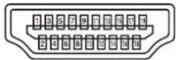
| No. | Function No. Function | ||
| 1 | TMDS data 2+ 11 TMDS clock shield | ||
| 2 | TMDS data 2 shield 12 TMDS clock- | ||
| 3 | TMDS data 2- 13 CEC | ||
| 4 | TMDS data 1+ 14 N.C. | ||
| 5 | TMDS data 1 shield 15 SCL | ||
| 6 | TMDS data 1- 16 SDA | ||
| 7 | TMDS data 0+ 17 DDC/CEC GND | ||
| 8 | TMDS data 0 shield 18 +5V | ||
| 9 | TMDS data 0- 19 Hot-plug detection | ||
| 10 | TMDS clock+ |
■DisplayPort input terminal pins
| No. | Function No. Function | ||
| 1 | N.C. 6 N.C. | ||
| 2 | Transmitted data | 7 N.C. | |
| 3 | Received data | 8 N.C. | |
| 4 | N.C. 9 N.C. | ||
| 5 | GND | ||
Mounting Precautions (For SHARP dealers and service engineers)
- When installing, removing or moving the monitor, ensure that this is carried out by at least 4 people. (PN-L651H: at least 2 people.)
- Be sure to use a wall-mount bracket designed or designated for mounting the monitor.
- This monitor is designed to be installed on a concrete wall or pillar. Reinforced work might be necessary for some materials such as plaster / thin plastic board / wood before starting installation.
- This monitor and bracket must be installed on a wall which can endure at least 4 times or more the weight of the monitor. Install by the most suitable method for the material and the structure.
- To attach a VESA-compliant mounting bracket, use M6 screws that are 5/16 inch (8 mm) to 3/8 inch (10 mm) longer than the thickness of the mounting bracket.
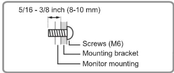
• Do not use an impact driver.
- When moving the monitor, be sure to hold the handles or the parts marked by below. Do not grasp the screen or tray. This may cause product damage, failure, or injury.

natural_image
Top-down schematic of a rectangular device with internal compartments and mounting brackets (no text or symbols)- If you need to temporarily place the monitor on a table or other surface during installation, spread a thick soft cloth on the table to prevent damage to the screen and table.
• Prior to repacking or removal, remove the tray and speaker covers.
• After mounting, please carefully ensure the monitor is secure, and not able to come loose from the wall or mount. - Do not use any screw holes other than those for mounting brackets, located on the rear of the monitor, for installation.
- When using this monitor tilted more than 20 degrees upward from the perpendicular in relation to a level surface, consult an authorized SHARP dealer because there are some specific mounting conditions.
■Attaching the Tray
Secure the tray using 5 tray mounting screws (M3x10) (supplied).
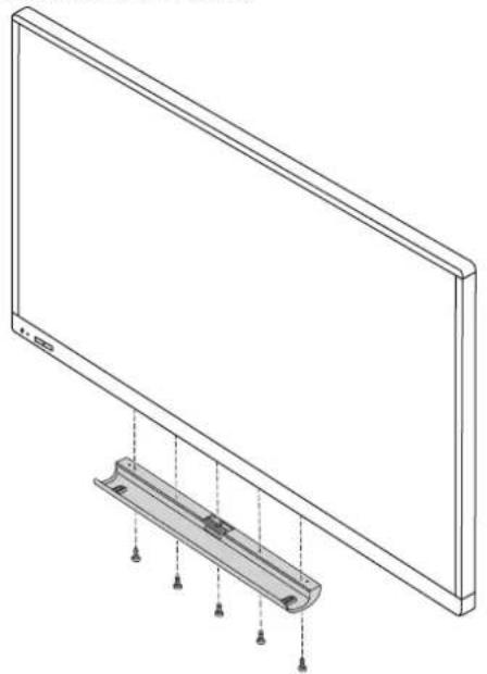
natural_image
Technical line drawing of a flat-screen monitor with a mounted rectangular panel and mounting holes (no text or symbols)■Attaching the speaker covers

If you will use the monitor in a portrait orientation, the speaker cover is not used.
SHARP®
SHARP CORPORATION

- CAUTION
- WARNING:
- NOTE:
- SAFETY PRECAUTIONS
- STABILITY HAZARD
- Especially for child safety
- The Power Cord
- Manual Scope
- LED Backlight
- Backward tilt installation
- Contents
- Supplied Components
- System Requirements
- Part Names
- TIPS
- ! Caution
- Connecting Peripheral Equipment
- DisplayPort output terminal
- Audio output terminal
- Wireless LAN antenna terminal
- LAN terminal
- 11.USBport
- microSD card slot
- USB hub (for computer) (USB 2.0 compliant)
- TOUCH PANEL1 terminal (for touch panel)
- TOUCH PANEL2 terminal (for touch panel)
- External speaker terminals
- Connecting the Power Cord
- !Caution
- Binding Cables
- Preparing the Remote Control Unit
- Installing the batteries
- Remote control operation range
- Removing the Handles
- Mounting a web camera
- Mounting on the tray
- Attaching the USB flash drive / SD card cover
- Attaching the wireless LAN antenna
- Turning Power On/Off
- ■Operations after first power-on
- Set POWER SAVE MODE
- Set the date/time
- Select "SET".
- Select "Set date".
- Set the date and select "OK".
- Select "Set time".
- Set the time and select "OK".
- Press the RETURN button on the remote control unit.
- Touch Pen
- Touch action
- ■Common finger and touch pen actions
- Single-tap
- Double-tap
- Swipe
- Swipe from edge of screen
- Drag-and-drop
- Flicks
- Press-and-hold
- Slide to pan
- ■Finger actions
- Zoom
- Press-and-tap
- Rotate
- Other functions
- Input panel :
- Cautionary points
- Eraser
- Basic Operation
- Using the touch menu
- Input mode selection
- Settings
- Backlight off
- FREEZE
- QUAD-SCREEN ON
- RECONFIGURE QUAD-SCREEN
- Exit touch menu
- HDMI
- Numeric input buttons
- MUTE
- MODE (Color mode selection)
- VOLUME +/- (Volume adjustment)
- INFORMATION
- FUNCTION
- ENTER
- FREEZE
- Buttons for operating the HDMI-connected device
- ID SET
- OPTION
- SIZE (Screen size selection)
- PIP/PbyP
- BRIGHT +/- (Brightness adjustment)
- BRIGHT 15
- INPUT (Input mode selection)
- MENU
- Cursor
- RETURN
- ■Switching the screen size
- Menu Items
- Displaying the menu screen
- ■Example of operation
- ■Menu screen display
- Configuring settings in the touch menu
- TOUCH OPERATION
- Menu item details
- ■SCREEN
- AUTO (D-SUB)
- CLOCK (D-SUB)
- PHASE (D-SUB)
- H-POS (D-SUB)
- V-POS (D-SUB)
- RESOLUTION SETTING (D-SUB)
- H-RESOLUTION
- V-RESOLUTION
- INPUT SIGNAL (D-SUB)
- RESET
- ■PICTURE
- BRIGHT
- CONTRAST
- BLACK LEVEL
- TINT
- COLORS
- SHARPNESS
- COLOR ADJUSTMENT
- COLOR MODE
- WHITE BALANCE
- PRESET
- USER
- COPY TO USER
- GAMMA
- C.M.S.-HUE
- C.M.S.-SATURATION
- ADVANCED
- ANALOG GAIN (D-SUB)
- ANALOG OFFSET (D-SUB)
- NR
- RGB INPUT RANGE
- DISPLAY COLOR PATTERN
- HDR (HDMI)
- AUDIO
- TREBLE
- BASS
- BALANCE
- SETUP
- DATE/TIME SETTING
- TIME FORMAT (when APPLICATION is ENABLE)
- DATE/TIME FORMAT (when APPLICATION is DISABLE)
- SCHEDULE (See page 40.)
- LANGUAGE
- INPUT SELECT
- DisplayPort STREAM
- HDMI MODES
- CEC SETTING
- HDMI CEC LINK
- AUTO POWER ON
- INPUT MODE NAME
- AUDIO SELECT
- AUDIO OPTION
- SPEAKER SELECT
- AUDIO OUTPUT
- AUDIO INPUT LEVEL
- MONAURAL AUDIO
- TOUCH INPUT SELECT
- START INPUT MODE
- COMMUNICATION SETTING
- MONITOR CONTROL SELECT (when APPLICATION is ENABLE)
- BAUD RATE
- REMOTE No.
- ■MULTI/PIP
- PIP/PbyP
- PIP MODES
- PIP SIZE
- PIP H-POS
- PIP V-POS
- PIP BLEND
- PIP SOURCE
- SOUND CHANGE
- MAIN POS
- PbyP2 POS
- CONFIGURE QUAD-SCREEN
- QUAD-SCREEN MODE
- SETTING INITIAL SCREEN
- PRIORITY: AUTO INPUT SEL.
- SAVE LAST INPUT CONFIG.
- TARGET: SOUND / INPUT SEL.
- RECONFIGURE QUAD-SCREEN
- INPUT SIGNAL INFO.
- OTHERS
- POWER MANAGEMENT
- CONNECT AUTO INPUT SELECT
- NO SIGNAL AUTO INPUT SEL.
- AUTO INPUT SELECT PRIORITY
- LOGO SCREEN
- VOLUME
- MUTE AUDIO
- MUTE WITH FREEZE
- BACKLIGHT OFF
- ■Dual-screen display
- ■Quad-screen display
- Displaying 4 screens
- Deciding the screen that will be the audio output/input mode selection target
- Returning to single screen
- ■SCHEDULE
- (1)
- POWER
- DAY OF THE WEEK
- TIME
- INPUT
- BRIGHT
- ■About remote control numbers
- Adjustments for computer screen display
- ■Automatic adjustment
- ■Screen display for adjustment
- Opening the adjustment pattern
- Initialization (Reset)/Functional Restriction Setting (FUNCTION)
- Press the FUNCTION button, and then press the MENU button within 10 seconds.
- Select and set the items.
- ALL RESET
- ADJUSTMENT LOCK
- ADJUSTMENT LOCK TARGET
- RS-232C/LAN
- OSD DISPLAY
- LED
- TEMPERATURE ALERT
- STATUS ALERT
- POWER BUTTON
- EXTERNAL CONTROLLER INPUT
- SIGNAL RESPONSE LEVEL
- APPLICATION
- APPLICATION RECOVERY MODE
- UPDATE MAIN SOFTWARE
- Press the RETURN button to return to the normal screen.
- Controlling the Monitor with a computer (RS-232C)
- Computer connection
- Communication conditions
- Communication procedure
- ■Command format
- ■Response code format
- ■Communication interval
- RS-232C command table
- How to read the command table
- Controlling the Monitor with a computer (LAN)
- Command-based control
- Connect the computer to the monitor.
- Send commands to control the monitor.
- Troubleshooting
- There is no picture or sound.
- Remote control does not work.
- The remote control unit's buttons for operating the HDMI-connected device do not work.
- Sound from left and right speakers is reversed.
- Sound is heard from only one side.
- There is a picture but no sound.
- Unstable video.
- The video from the HDMI input terminal does not appear properly.
- The video from D-Sub input terminal does not appear correctly.
- The video from the DisplayPort does not appear properly.
- Control buttons do not work.
- There is no picture.
- The input mode changes automatically.
- The touch panel does not respond.
- The response of the touch panel is slow.
- Some parts of the screen do not respond.
- A different place is touched.
- Power LED illuminates in blue and orange alternately.
- "STATUS [xxxx]" appears in the corner of the screen.
- When "AUTO DIMMING" is displayed.
- The monitor makes a cracking sound.
- Power LED is flashing in orange and blue alternately. When “TEMPERATURE” is displayed in the corner of the screen.
- Specifications
- ■DDC (plug and play)
- ■HDMI input terminal pins
- ■DisplayPort input terminal pins
- Mounting Precautions (For SHARP dealers and service engineers)
- ■Attaching the Tray
- ■Attaching the speaker covers
- SHARP®
- SHARP CORPORATION
Brand : SHARP
Model : Aquos Board PN-L851H
Category : Desktop computer