
DNR-2060-08P - Voice recorder D-LINK - Free user manual and instructions
Find the device manual for free DNR-2060-08P D-LINK in PDF.


| Product Type | 6-Bay Network Video Recorder (NVR) |
| Brand | D-Link |
| Model | DNR-2060-08P |
| Dimensions (H x W x D) | 90.4 mm x 440.4 mm x 450.9 mm (3.56 in x 17.34 in x 17.75 in) |
| Weight | 9.02 kg (19.9 lbs) |
| Power Input | AC 100-240V, 50/60 Hz |
| Power Output (USB) | 5V DC, 750 mA |
| Number of HDD Bays | 6 internal bays (3.5 inch SATA) |
| Maximum Storage Capacity | Up to 18 TB (with 3TB HDDs) |
| PoE Ports | 8 ports (IEEE 802.3at), total power budget 90W |
| Video Compression | H.264, MJPEG; JPEG for still images |
| Recording Resolution | Up to 1080P per channel (camera dependent) |
| Recording Performance | NTSC: 240pps at 1080P; PAL: 200pps at 1080P (8 channels total) |
| Video Output | HDMI, VGA (up to 1080p) |
| Network Interface | 1 x Gigabit RJ-45, 8 x 10/100 PoE RJ-45 |
| USB Ports | 3 x USB 2.0 (front and rear) |
| e-SATA Port | 1 (rear) |
| Audio | RCA audio out; PCM/G.711 |
| Alarm I/O | 8 alarm inputs, 8 relay outputs |
| Remote Access | Via web browser (IE, Firefox, Safari, Chrome) and mobile apps (iOS, Android) |
| Playback Features | Search by time, event, calendar, panorama; forward/reverse playback at various speeds |
| Included Accessories | 6 SATA cables, remote control with batteries, power cord, mounting kit, software CD, quick installation guide, screws |
| Operating Temperature | 0 to 40 °C (32 to 104 °F) |
| Certifications | CE, FCC, CE LVD, C-Tick |
Frequently Asked Questions - DNR-2060-08P D-LINK
User questions about DNR-2060-08P D-LINK
0 question about this device. Answer the ones you know or ask your own.
Ask a new question about this device
Download the instructions for your Voice recorder in PDF format for free! Find your manual DNR-2060-08P - D-LINK and take your electronic device back in hand. On this page are published all the documents necessary for the use of your device. DNR-2060-08P by D-LINK.
USER MANUAL DNR-2060-08P D-LINK
Version 1.0 | 04/25/2013
User Manual
6 Bay Network Video Recorder
DNR-2060-08P
Preface
D-Link reserves the right to revise this publication and to make changes in the content hereof without obligation to notify any person or organization of such revisions or changes. Information in this document may become obsolete as our services and websites develop and change.
Manual Revisions
| Revision Date Description | |
| 1.0 April 25, 2013 DNR-2060-08P Rev | sion A1 with firmware version 1.00 |
Trademarks
D-Link and the D-Link logo are trademarks or registered trademarks of D-Link Corporation or its subsidiaries in the United States or other countries. All other company or product names mentioned herein are trademarks or registered trademarks of their respective companies.
Copyright © 2013 D-Link Corporation.
All rights reserved. This publication may not be reproduced, in whole or in part, without prior expressed written permission from D-Link Corporation.
Table of Contents
Product Overview 5
Package Contents 5
Introduction 6
System Requirements 6
Features 7
Hardware Overview 8
Front Panel Function Keys 8
Front Panel LED Indicators 9
Rear Panel 10
Hard Disk Drive Installation ....11
Connecting a Power over Ethernet IP Camera .....13
Remote Control Operation ....14
USB Mouse Operation ....15
USB Keyboard Operation ....16
Jog/Shuttle Control 17
Function Keys ....18
Basic Operation 20
Viewing Modes ....20
Digital Pan and Zoom 22
Freeze Live Video 22
View Recorded Video....23
Key Usage in Playback 23
Pause, Playback and Single Step Forward .....24
Search Recorded Video 24
Search by Time 25
Calendar Search 26
Search and Playback with the Event List ....27
Panorama Search 28
Search by Text 29
Dome Control....30
Set Preset Points 32
Call Preset Points 32
Run Dome Camera Tour ....33
Quick Video Export through Front Panel ....34
Advanced Operation 35
System Menu 35
User Management ....36
System Date / Time Setting 37
Set Date/Time 38
Daylight Saving Time ....39
Network Time Protocol Setup ....40
Network Setup 41
Dynamic DNS 41
UPnP Function 42
UPnP NAT Traversal Function 43
Monitor Menu 44
Camera Menu 46
Connection Setup 48
Device Setup 50
Activated 50
Status....51
Copy Settings 51
Record Menu 52
Record Schedule / Quality Setting ....53
Table of Contents
Schedule Setup ....53
Preset Record Configuration ....54
Per Camera Configuration ....54
Record Event Video Only 54
Data Lifetime Setup 55
Pre-Alarm Recording 56
Circular Recording 56
Audio Recording 57
Purge Data 57
Sequence Menu ....58
Event Menu 60
Database Menu 66
Repair on Power Loss 68
Configuration Menu 69
Export Menu 71
Export Video 72
Aux Menu 75
Shutdown Menu 77
Using the Web Interface 79
Web UI System Requirements 79
Web UI Setup 80
Change Internet Settings 80
Install Web UI Browser Plugins 82
Log in/Log off 83
Firmware Upgrades 84
Web UI Basic Operation 84
Live Video 84
Select Display Mode 85
Operate Cameras with Dome Control 86
Digital Zoom of Camera Display 87
Manually Trigger Relay Output Devices 88
Instant Recording 88
Record Video Instantly 88
Playback Instant Recorded Video 88
Playback Video 89
Remote Playback 89
Playback Local *.drv Files 90
Playback Controls 90
Verify Digital Signature 91
Search from Event List 91
Take a Snapshot 92
Health Status of HDD 92
Normal and Dual Streaming 93
Web UI Advanced Operation 94
Remote Firmware Upgrade/Remote NVR Reboot ..94
Firmware Troubleshooting 95
Appendix A: Recommended HDDs 96
DI/DO Specifications 97
Technical Specifications 98
Product Overview Package Contents
- Six SATA Cables
- Remote Control
- Power Cord
- Mounting Kit
- Software CD
- Quick Installation Guide
- Two Batteries for Remote Control
8.24 Screws
natural_image
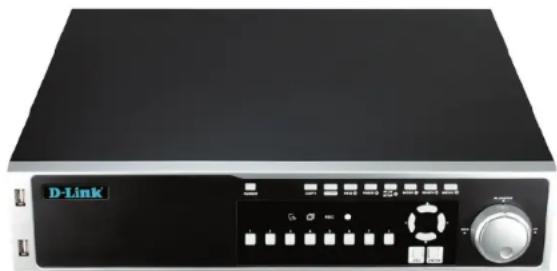
Front view of a black D-Link electronic device with control panel and buttons (no readable text or symbols)If any of the above items are missing, please contact your reseller.
Note: Using a power supply with a different voltage than the one included with your product will cause damage and void the warranty for this product.
Introduction
The DNR-2060-08P 6-Bay Network Video Recorder is a comprehensive standalone network video display, storage, and management solution providing reliable high-quality remote monitoring for IP-based security systems. The DNR-2060-08P enables simultaneous recording and remote access to recorded video as well as live viewing. Controlling the DNR-2060-08P is exceptionally easy using conventional front panel controls, with an optional keypad and mouse, or remote control handset. High flexibility, simple configuration, and easy management make the DNR-2060-08P a cost-effective upgrade addition to your security and surveillance infrastructure.
Please note that the model you have purchased may appear slightly different from those shown in the illustrations.
System Requirements
Computer with Microsoft Windows ^® 7, Vista ^® , or XP (for CD-ROM Setup Wizard), Mac OS or Linux PC with 1.3GHz or above; at least 128MB RAM Internet Explorer 7 or above, Firefox 3.5 or above, Safari 4 and Chrome 8.0 or above Existing 10/100 Ethernet-based network
Features
Comprehensive IP Surveillance Solution
Total Solution: The D-Link NVR is a standalone network video recorder capable of 24/7 recording without a PC. The NVR can manage multiple network cameras, providing direct access to view live video and play recorded data through the Internet from anywhere anytime.
Easy to Use: A user-friendly GUI simplifies network and camera setup, allowing users to easily access multiple cameras for viewing, recording, playback, and configuration.
Centralized Interface for Configuration: NVR provides a flexible and economic alternative to manage and configure multiple Network cameras on a centralized web interface.
Megapixel Resolution Support: The major advantage of digital over analog video is its higher resolution support. The NVR supports high resolution megapixel recording for vivid video with high clarity.
Integrated 8 Channel PoE Switch: The DNR-2060-08P can be easily setup for internet access. It supports real-time monitoring and playback from everywhere via IE browser. The recording store in your own HDD with high privacy, not in the cloud.
Six 3.5" HDD for upto 18TB of storage: with upto 18TB of local storage you can keep a massive archive of High Definition recording while retaining your privacy instead of relying on the cloud.
Complete Connectivity
DDNS Support: Dynamic DNS is a solution for users without a fixed IP address. With DDNS service, users can connect to the NVR from the Internet using an easy-to-remember domain name.
NTP Support: Maintaining an accurate record of time is essential if recorded data is to be used as evidence. To ensure that the time recording is always accurate, the NVR can update the system clock from an Internet server using the Network Time Protocol (NTP).
3 x USB 2.0, and e-SATA: Convenient connectivity and complete flexibility.
Fully Functional Recording
Flexible Recording Schedule: Once cameras have been set up, a highly configurable scheduling system allows for continuous recording or recording during specifically allotted time frames. Each camera can be set to record independently at preset intervals. It also provides event recording based on specific triggers.
Recording Automatic Overwrite: The NVR can be configured to overwrite the oldest data automatically when Hard Disk space runs out, allowing for continuous and uninterrupted recording. Users can specify the number of days the recording should be kept (within the limits of the Hard Disk capacity). For example, if the NVR has the capacity to store 7 days of recording, using the overwrite option, the NVR will record the 8th day and delete the 1st day.
natural_image
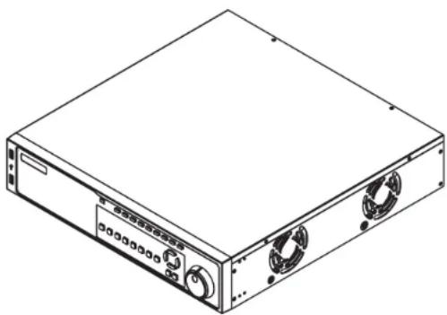
Isometric line drawing of a rectangular electronic device with two ports and cooling fans (no text or symbols)Hardware Overview
Front Panel Function Keys
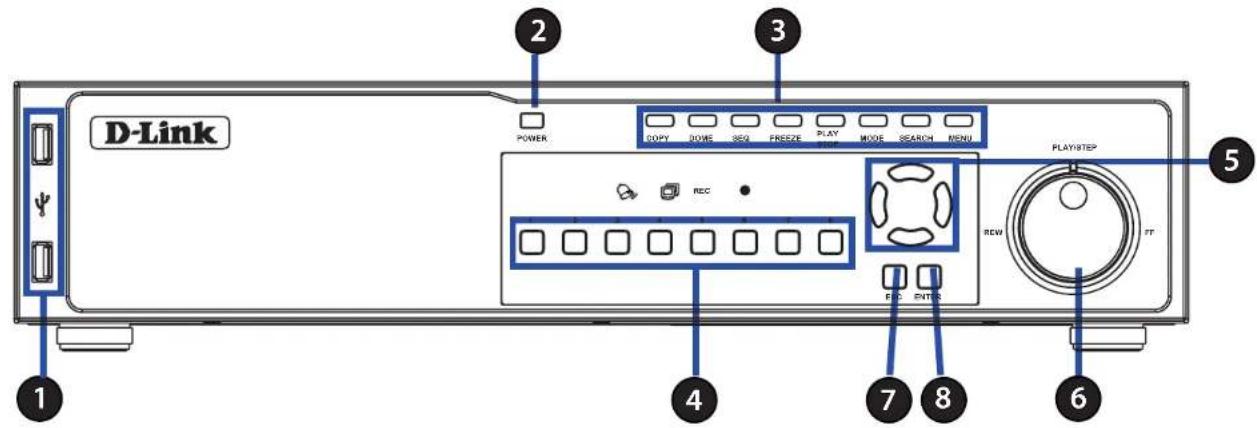
| 1 | USB 2.0 Port | Allows users to connect an external USB device to the unit, such as a USB Drive or a USB mouse. |
| 2 | Power Press this switch to power | on the NVR. Press and hold for quick shutdown of the NVR.. |
| 3 | Function Keys | Allows users to select various functions. See "Function Keys" on page 18 |
| 4 | Channel Select Button: 1-8 | In Live and Playback modes, press any button to view the corresponding video in fullscreen. |
| 5 | Arrow Keys | In Zoom mode, these buttons function as direction buttons.In the OSD setup menu, the direction buttons are used to move the cursor to previous or next fields.To change the value in the selected field, press UP/DOWN buttons. |
| 6 | Shuttle/Jog This is used to control playback operations. | |
| 7 | Esc Button | Press this button to cancel or exit from a control mode. |
| 8 | Enter Button | In the OSD menu or selection interface, press this button to make the selection or save settings.In live full-screen viewing mode, press this button to view zoom; press it again to return to normal. |
Front Panel LED Indicators
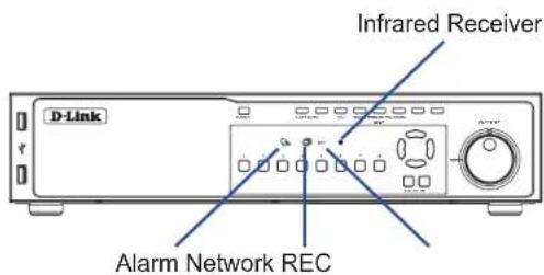
The LED incators on the front panel of the NVR function as follows.
| Network The Network | icon lights up when the NVR is connected to a network and blinks when data is being transferred. | |
| REC | REC The Recording | icon blinks while the NVR is recording. |
| Alarm | The Alarm icon lights up when an alarm is triggered. | |
| IR Receiver | The infrared receiver receives signals from the remote control. |
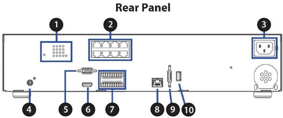
| 1 PoE/Link Indicators | The lit orange LED signifies that the IP camera is connected and power is supplied via PoE. When the LED is off, either the power is separately connected or the IP camera is not connected. The blinking green LEDs represent data being transmitted from the IP cameras to the NVR. When the LED is not on, that means the IP camera is not connected. |
| 2 PoE Ports | The optional PoE ports offer direct connections to eight IP cameras. The IP cameras can be “plug and play” if the function is enabled in the OSD menu. |
| 3 Power Socket | Connect the power supply cord shipped with the NVR. |
| 4 Main Audio Out | A RCA connector is provided to output audio associated with the main monitor. |
| 5 Main Monitor (VGA) A VGA output connector is offered for connecting to a VGA monitor. | |
| 6 Main Monitor (Digital Output) | A digital output connector is provided for connection to a displaying device that transfers data digitally to show the best video quality. |
| 7 Alarm I/O | The NVR provides alarm I/O that offer users flexibility to connect the unit to other devices. |
| 8 LAN 10/100/1000M (RJ-45) | The NVR is capable of networking and it allows videos to be viewed over the LAN network or the Internet by using Internet Explorer. |
| 9 e-SATA Port | Users can connect an e-SATA storage device via this port. |
| 10 USB 2.0 Port | Allows users to connect an external USB device to the unit, such as a USB Drive or a USB mouse. |
Hard Disk Drive Installation
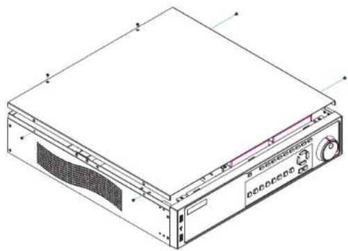
Step 1
Use a screwdriver to remove the screws from the sides and top of the NVR, then lift the cover.
natural_image
Isometric line drawing of a computer rack unit with ventilation slots and control panel (no text or symbols)Step 2
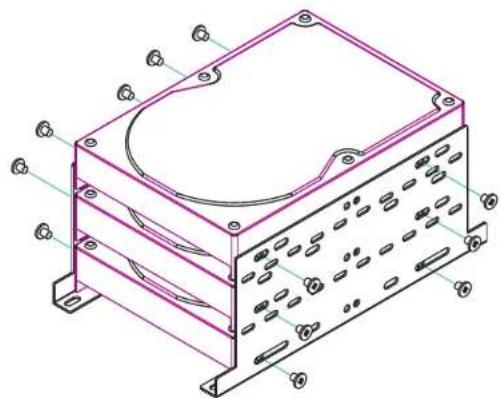
Locate the two 3-bay hard drive racks inside. Select the rack you would like to install your hard drive into, then slide the hard drive into the rack bay.
natural_image
Technical line drawing of a mechanical housing or enclosure with mounting brackets and internal components (no text or symbols)Step 3
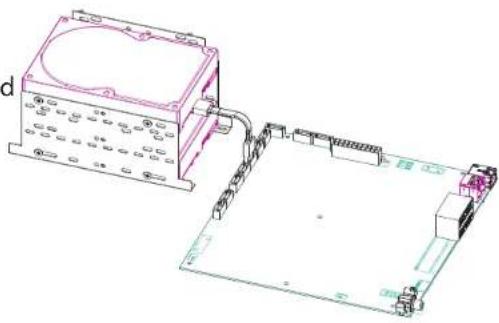
Attach one end of the SATA cable to the rear of the HDD.
Attach the other end of the SATA cable to a free SATA socket on the motherboard of the NVR.
natural_image
Technical line drawing of an electronic device with components and wiring (no text or symbols)Step 4
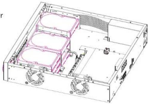
Secure the hard drive in place with screws using the guide holes along the center of the sides.
natural_image
Isometric technical drawing of a server rack with internal components and ventilation ducts (no text or labels)Connecting a Power over Ethernet IP Camera
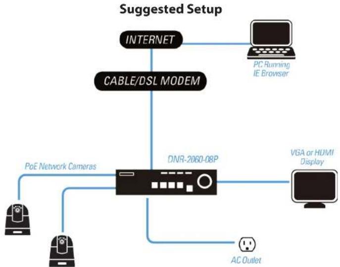
The NVR has a built-in PoE switch accessible via the rear panel. This provides both network connectivity and power for up to eight PoE IP cameras with a single cable.
Note: The maximum power for all connected devices must not exceed 90 Watts.
Step 1
Make sure the NVR is connected to a network via a router or a switch, or directly connected to a PC. Plug in cameras using the PoE ports on the rear panel.
Step 2
The NVR will boot up and start to record automatically.
flowchart
graph TD
    A["INTERNET"] --> B["CABLE/DSL MODEM"]
    B --> C["DNR-2060-08P"]
    C --> D["PC Running IE Browser"]
    C --> E["POE Network Cameras"]
    C --> F["AC Outlet"]
    C --> G["VGA or HUMI Display"]
Remote Control Operation
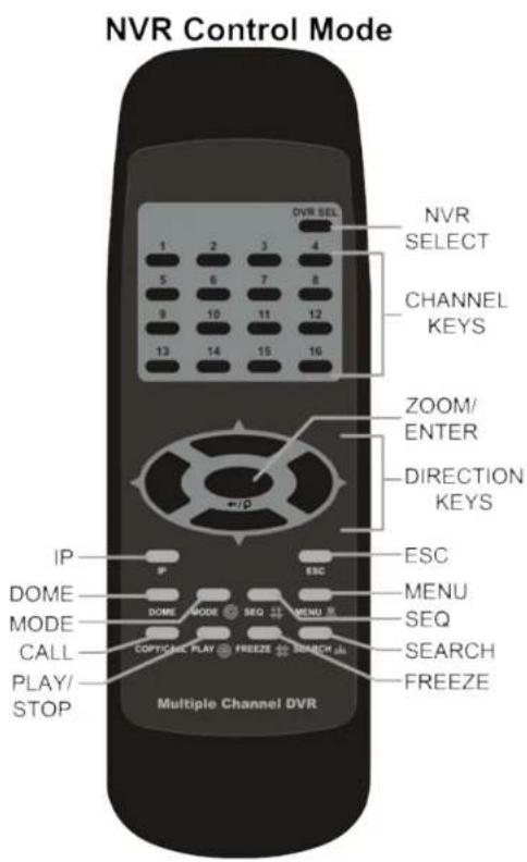
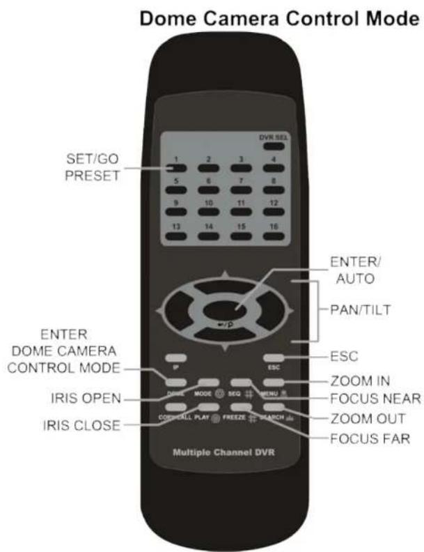
A remote control is provided for the NVR. The operational function keys (on the left) and dome camera control keys (on the right) on the remote control are listed as below figure:
USB Mouse Operation
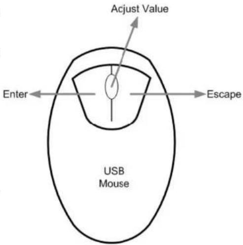
Users can attach a USB mouse to control the NVR. To use a USB mouse, plug a USB mouse into any USB port of the NVR.
Move the cursor to the right side of the screen and a Live Panel will be displayed. The icons on the Live Panel are the same as the function keys on the front panel of the NVR.
Clicking the left button operates the same as pressing the ENTER key. Clicking the right button operates the same as pressing the ESC key. The scroll wheel is used to change values. For example, if users want to change dome camera ID, enter the OSD setup menu with an authorized account and go to the following path: Camera, Connection Setup, IP Dome ID.
Left click on IP Dome ID and scroll the mouse wheel up or down, the ID number will change as the scroll wheel moves. Stop moving the scroll wheel when the preferred ID number appears, then left click on the IP Dome ID to select the ID Number and the ID number will be changed.
Camera Title Alignment
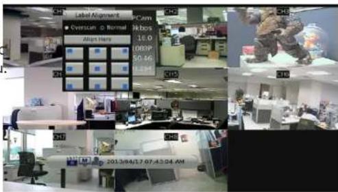
Users can change the display position of camera titles of all channels. To change the camera title position for a single channel, left click on the camera title and drag the title to a preferred position. If users want to set all of the camera titles to the same position that is set for a specific channel, right click on the specific camera title and select Align Here from the pull-down menu.
Note: Users can access the OSD menu with an authorized account and go to Monitor, Mouse Sensitivity to setup preferred sensitivity level of USB mouse.
USB Keyboard Operation
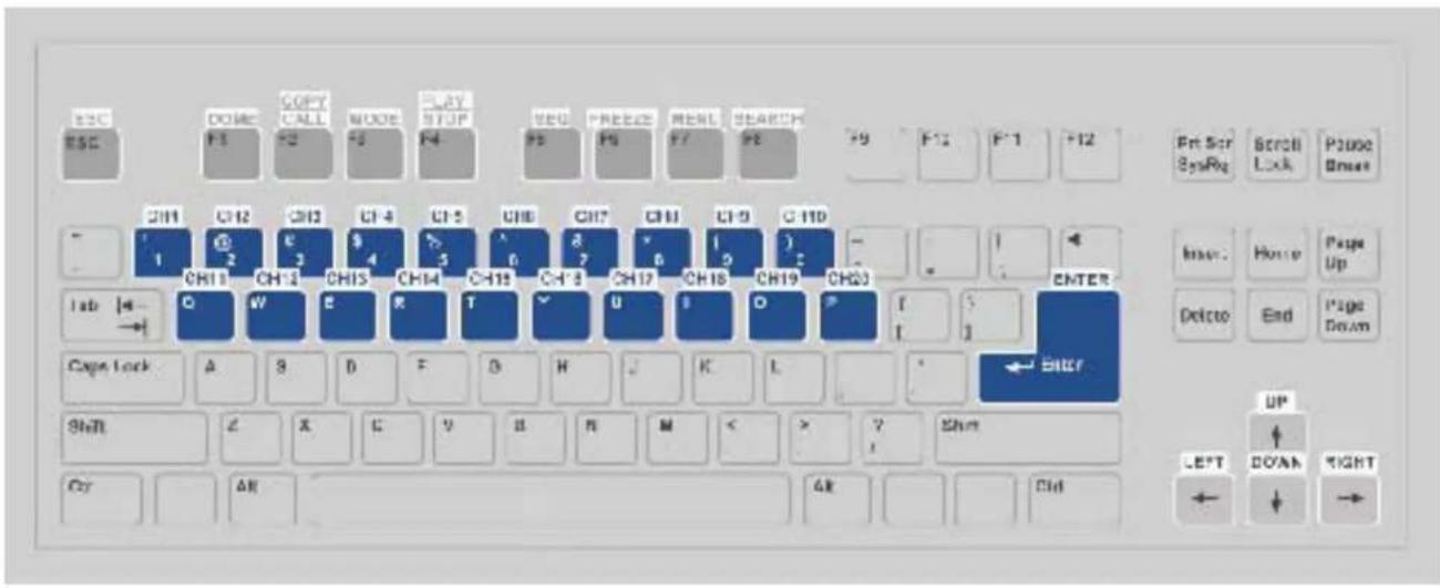
The following diagram shows the keys used to access and control the NVR from an attached USB keyboard.
Jog/Shuttle Control
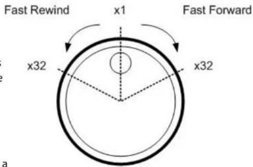
The jog/shuttle dial is used to provide a wide latitude in playback control. Note that the jog/shuttle dial is active only when the NVR has been in Playback mode.
While playing back recorded video, users can rotate the shuttle ring to select different speed of forward and reverse playback. Rotating the shuttle ring clockwise/ counterclockwise causes the unit to playback faster forward/backward. According to the angle of rotation of the shuttle ring, users can choose a playback speed from 1×, 2×, 4×, 8×, 16×, and 32×, in both forward and reverse directions.
Inside the shuttle ring is the jog disk.
Once the video is paused, users can use the jog disk to playback video frame-by-frame. Clockwise rotation causes a one-step forward playback; and counterclockwise rotation causes a one-step backward playback.
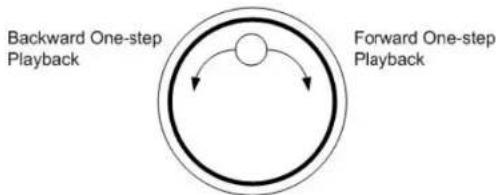
flowchart
graph TD
    A["Backward One-step Playback"] --> B(( )) --> C["Forward One-step Playback"]
    C --> A
Function Keys
This section describes the function keys for normal operation, on the front panel of the NVR.
| [G8DB] | POWER After the power cord is correctly connected, press this key to switch power on. Press and hold this key to quick shutdown the NVR. |
 | CHANNEL In both Live and Playback modes, press the CHANNEL key to view the corresponding video in full-screen. The number of the CHANNEL keys corresponds to the number of cameras supported by the unit.In Dome Control mode, the key "1" is used to access the Set/Go preset menu; the keys "11" ~ "16" are for quick access of preset points 1~6. |
 | COPY In Playback mode, press this key to select the start and end time of the export video.Refer to section Video Export for detailed information. |
 | DOME Press the key to enter Dome Control mode. Please refer to Section Dome Control for detailed controlling operation. |
 | MODE Press repeatedly to select desired main monitor display format. According to the monitor displaying type, there are several available viewing modes: full-screen, 2-windows, and 8-windows. Refer to section Viewing Modes for detailed information. |
 | PLAY Press this key to switch between live image and playback video.Note: The video of latest 5~10 minutes cannot be played back because the video is still saved in the buffer. |
 | FREEZE Press FREEZE while viewing live image, the live video will be frozen. The date / time information shown on the monitor will continue updating, as well as the recording of video. Press FREEZE again to return to live mode. Press FREEZE while playing the recorded video, the playback video will be paused. Press LEFT / RIGHT to move the recorded video reverse / forward by single step. Press FREEZE again to continue playing video. |
 | SEQ (Sequence) Press to start automatic sequence display of video from all installed cameras. |
 | SEARCH In both Playback and Live mode, press SEARCH to enter the Search menu for searching and playing back recorded video by date / time, event, or text. |
 | MENU Press this key to enter the OSD setup menu. |
Section 2: System Setup
Direction Keys In  | Zoom mode, these keys function as Direction keys.In the OSD setup menu, the LEFT / RIGHT keys are used to move the cursor to previous or next fields. To change the value in the selected field, press UP / DOWN keys. | |
 | ESC Press to cancel | or exit from certain mode or OSD setup menu without changing the settings made previously.When password protection is switched off, press ESC for five seconds to lock UP the system. Press ESC for five seconds again to unlock.Note: Enter the OSD menu and go to System User Management to enable or disable the password protection. |
 | ENTER / ZOOM | In OSD setup menu or selection interface, press this key to make the selection or save settings.In live full-screen viewing mode, press this key to view a 2× zoom image; press it again to return. |
JOG / SHUTTLE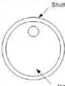 | The jog/shuttle knob, is a combination of a shuttle ring with an embedded jog disk.It provides wide latitude in playback control. Note that the jog/shuttle knob is active only when the NVR is in Playback mode.Please refer to Appendix F: Jog / Shuttle Control for further information. |
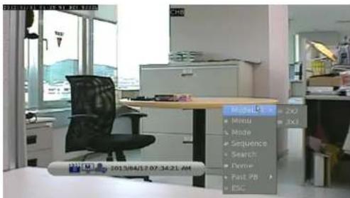
Note: If a USB mouse is present you can right click anywhere on screen to access a menu system replicating the features of the front panel function buttons.
Basic Operation Viewing Modes
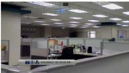
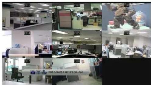
The NVR has three different viewing modes.
Press a CHANNEL button to view the corresponding IP camera in full-screen mode.
Press the MODE button to switch to the next available viewing modes.
natural_image
Interior view of an office with cubicles and ceiling lights (no visible text or symbols)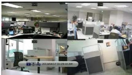
natural_image
Interior view of an office with cubicles and desks, showing two scenes with a person in the center (no visible text or symbols)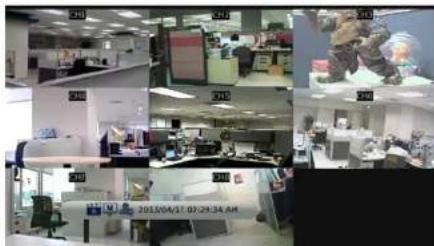
1 x 1, Single Channel, Fullscreen View 2 x 2, Four Channel, Grid View 3 x 3 (9 - 1), Eight Channel, Grid View
Section 3: Front Panel Operation
By default the NVR shows the title of the channel at the top-center of the channel feed, both in full-screen mode or in multiple channel mode. To change the placement of the title please see "Camera Title Alignment" on page 1\$
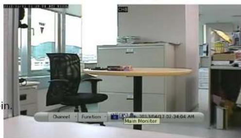
The current operation status and date/time information will be displayed in the status bar at the bottom of the screen.
An icon displayed on the status bar shows the authority level of the account currently logged-in. If no user is logged in, the icon displayed will be a guest icon. When an account is logged in, its authority level number (1 to 8) will be shown.
Move the cursor to any status bar icon and its description will be displayed.
Digital Pan and Zoom
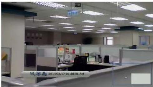
Users are able to view a 2× full-screen in both live and playback mode.
To view the 2× full-screen:
- Press a CHANNEL key to view the corresponding camera in full-screen.
- Press ENTER to view 2× zoomed screen of the selected camera.
A zoom icon will appear on the status bar and a frame will appear in the bottom right of the screen identifying the portion of the view available.
To pan to a specific area within the zoomed screen, use the Direction keys to navigate within the frame.
Press ENTER again or press ESC to leave the Zoom mode.
natural_image
Interior view of a modern office with cubicles and ceiling lights (no visible text or symbols)Freeze Live Video
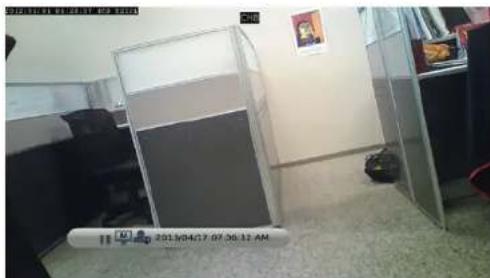
Users can freeze the live video at any time. Press the FREEZE button while viewing live video and the image will be frozen immediately and a pause icon will appear on the status bar.
Note: The date and time information will not pause, the system clock will keep running. Press the FREEZE button again to resume Live monitoring in real time.
View Recorded Video
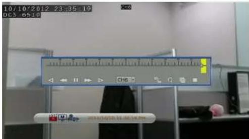
To view recorded video, users can press the PLAY key directly. After pressing the PLAY key, the NVR will resume playback of the recorded video from the point where recording was suspended. If it is the first time using the PLAY key, the NVR will playback from the beginning of recording.
Alternatively, users can select records from the Search menu to playback specific video. Refer to "Search Recorded Video" on page 24 for further information.
Key Usage in Playback
The front panel keys operate differently while the NVR is in Playback mode.
LEFT (Reverse Playback)
Press this key to reverse the recorded video. Press the key repeatedly to increase the speed of reverse playback by 1×, 2×, 4×, 8×, 16×, or 32×.
RIGHT (Fast Forward Playback)
Press this key to fast forward the recorded video. Press the key repeatedly to increase the speed of fast forward playback by 1×, 2×, 4×, 8×, 16×, or 32×.
FREEZE
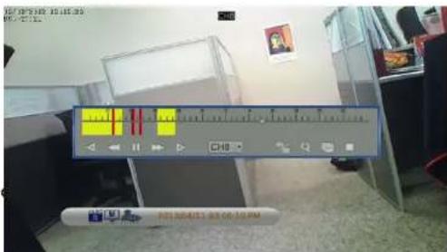
Press FREEZE to pause the video playback. When the recorded video is paused, press LEFT/RIGHT to single step reverse/forward video playback respectively. Press FREEZE again to resume video playback.
PLAY
Press to start video playback or return to live mode.
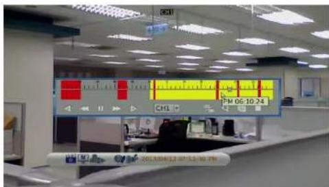
Pause, Playback and Single Step Forward
To pause and resume recorded video:
Press any CHANNEL key to view the corresponding camera in full-screen.
Press FREEZE to pause the current playback image.
Press RIGHT/LEFT Direction keys to move the video single step reverse/forward.
Press and hold RIGHT/LEFT keys to repeatedly reverse/forward the video single step.
Press FREEZE again to resume the playback operation.
Search Recorded Video
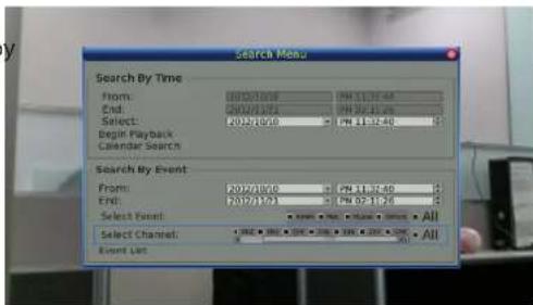
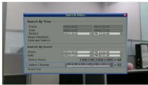
The NVR can search and play back recorded video by date/time, events, or text. To search by time, select a specific date and time of the wanted video or enter Calendar Search. To search by event, select the channels to display in the event list. In Live or Playback mode, press SEARCH to enter the Search menu.
Note: Search By Text only functions when a POS machine is connected and text data is stored.
Search by Time
To search video by date and time:
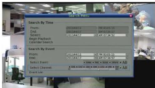
Press SEARCH to enter the Search menu.
Move the cursor to From and press ENTER to specify the start of video playback time. Move the cursor to End and press ENTER to specify the end of video playback time. Move the cursor to Select and press the LEFT/RIGHT keys to choose date/time. Press ENTER and adjust the values by using the UP/DOWN keys.
Press ENTER to confirm the settings or ESC to abort.
Move the cursor to Begin Playback and press ENTER to start playing back the selected video.
Press PLAY again to return to live video.
Note: If there is no available recorded video that matches the specified time and date, the unit will playback the next available video.
Note: The date/time information will be shown on the screen with a DST icon if the Daylight Saving Time function is enabled. S indicates summer time and W indicates winter time.
Calendar Search
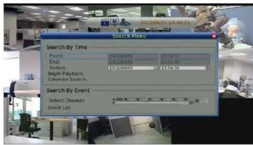
To search recorded video via Calendar Search:
Press the SEARCH button to enter the Search menu.
Move the cursor to Calendar Search and press ENTER.
The Calendar Search window will appear.
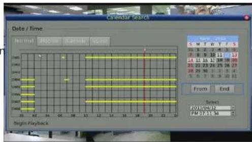
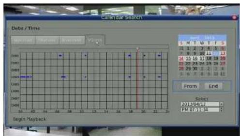
The Calendar Search window has four tabs to filter events Normal (all), Motion, Alarmin and VLoss (video loss). Select the appropriate tabe for the event type you wish to view.
Move the cursor to year/month and press ENTER then press the UP/DOWN keys to adjust the value and press ENTER again to confirm.
Move the cursor and press ENTER to select any date shown in bold and underlined font. The bar below the calendar will change according to the recorded data of the selected date.
Select the preferred time from the time bar or alternatively, move the cursor to the time shown at the bottom. Press ENTER and adjust the values of hour/minute/second with the UP/DOWN keys.
The From and End buttons allow users to playback video from the beginning or end of the database.
Note: Recorded events are displayed by colored time blocks.
Select Begin Playback and press ENTER to start playing back selected video.
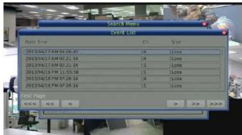
Search and Playback with the Event List
The Event List allows users to search for video by event. The list displays events by date, time, triggered camera and alarm type. As older events are deleted newer ones are displayed. The latest recorded event video will be listed on the top.
To search for recorded events with the Event List:
Press SEARCH to enter the Search menu.
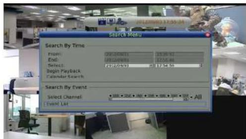
To search for recorded events from a specific camera, use the LEFT/RIGHT keys to move the cursor and press ENTER to select or de-select a channel.
Move the cursor to the Event List and press ENTER to list the recorded events of the selected channels.
To exit the event list, press ESC.
To playback video from the Event List:
Press and hold UP/DOWN to select from the Event List. Press ENTER to play back the selected event recording. Press PLAY to return to Live mode.
Panorama Search
In addition to the various search methods previously outlined, the NVR also provides users a different way to search for video of one specific channel via preview images, called panorama search.
To use panorama search:
Start to playback video of one specific channel in full-screen mode.
Press FREEZE and the video will be paused.
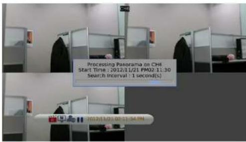
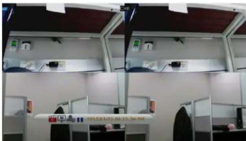
Press MODE once. Panorama search will start and the preview images will be in 1 second intervals, with 20 preview images displayed.
Press the LEFT/RIGHT keys and the previous/next 20 preview images in 1 second intervals will be displayed.
Press the MODE key a second time and the panorama search preview will be refreshed in 1 minute intervals.
Press MODE a third time and the panorama search preview will be refreshed in 1 hour intervals.
Press MODE a fourth time and the panorama search preview will be refreshed in 1 day intervals.
Move the cursor to the preview frame and click on it to start playback the video from the selected frame.
Press PLAY to return to Live mode.
Search by Text
When a POS device is connected to the NVR, users can search for videos with text data.
There are three ways to search: by text, by numerals, or by text and numerals.
Additionally, a date/time and/or channel range can be specified to narrow down the query, enabling faster searches.
By Text:
Exception: Search for video with data containing the exception string set in the OSD setup menu.
OR: Enter two sets of word strings. Search for videos with data containing either of the word strings.
AND: Enter two sets of word strings. Search for videos with data containing both of the word strings.
Specific: Specify one set of word string. Search for videos with data containing the specific word string.
By Numerals:
Outside The Range: Enter two numbers to specify a range. Search for videos with data containing number(s) out of the range.
Inside The Range: Enter two numbers to specify a range. Search for videos with data containing number(s) within the range.
Less Equal Than: Enter one number. Search for videos with data containing number(s) less than or equal to the specific number.
Greater Equal Than: Enter one number. Search for videos with data containing number(s) greater than or equal to the specific number.
Specific: Specify a number. Search for videos with data containing the specific number.
Dome Control
The NVR allows users to control a dome camera via the function keys on the front panel. In Live mode, users can press a CHANNEL key to display the desired dome camera in full-screen. To enter Dome Control mode, press the DOME key and a dome control panel will be displayed. To exit the Dome Control mode and return to Live mode, press ESC or DOME.
The Dome Control Panel buttons are listed below.
Iris Close: Adjust the camera's iris to a more closed position.
Iris Open: Adjust the camera's iris to a more open position.
Focus Far: Adjust the camera's focal point to a more distant point.
Focus Near: Adjust the camera's focal point to a nearer point.
Zoom Out: Zoom out the lens of selected dome camera. This function enables users to shrink the current image and a larger viewing area can be displayed.
Zoom In: Zoom in the lens of selected dome camera. This function enables users to enlarge a certain area.
Preset: This key is used to enter the Dome Preset menu to setup a certain position as a preset and go to the predetermined preset positions for viewing.
Live: Click on it to exit Dome Control mode and return to live full-screen viewing mode.
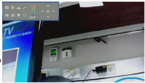
Pan/Tilt Speed: Users can select preferred pan/tilt speed.
Section 3: Front Panel Operation
Direction Buttons: Click on the buttons to pan and tilt the lens of selected dome camera.
Auto Focus: Click on this button to automatically adjust focus of the dome camera.
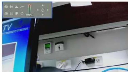
Note: The front panel keys can also perform the functions listed above. Please refer to "Front Panel Function Keys" on page 8 for further details of function keys.
Set Preset Points
The NVR allows you to define a path made up of a number of preset positions. The number of preset points on a path is dependent on the dome camera manufacturer.
To set preset points:
Press a Channel key to view the corresponding camera in full-screen.
Press DOME to the enter Dome Control mode. The dome control panel will be displayed.
Use the direction keys to pan/tilt the dome camera to desired position.
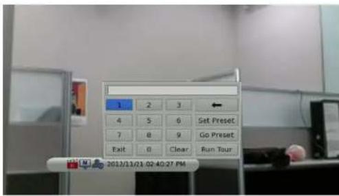
Click Preset on the dome control panel or press CH1 key to access the Set/Go Preset function. The numeric keyboard will be displayed as below.
Input a desired preset number.
Click on the Set Preset button to save the position. Now the preset position is set and ready to be called.
Call Preset Points
To call preset points:
Press a Channel key to view the corresponding camera in full-screen.
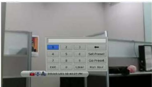
Then press DOME to enter Dome Control mode. The dome control panel will be displayed. Click Preset on the dome control panel or press CH1 key to access the Set/Go Preset function. The numeric keyboard will be displayed.
Input a desired preset number.
Click on the Go Preset button to call the preset point. The selected dome camera will rotate to the preset position automatically.
Run Dome Camera Tour
Users can also display dome camera tour setup at the dome camera side.
To run display of dome camera tour:
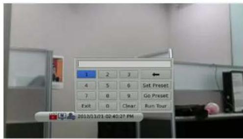
Press a Channel key to view the corresponding camera in full-screen. Then press DOME to enter Dome Control mode. The dome control panel will be displayed. Click Preset on the dome control panel or press CH1 key to access the Set/Go Preset function. The numeric keyboard will be displayed.
Click on the Run Tour button to run the display of dome camera tour. Press any of the Direction keys to end the display of dome camera tour.
Quick Video Export through Front Panel
Using the front panel function buttons, the NVR allows users to easily export video as *.drv files to an external device such as a USB. To export video to an external device, make sure the device is connected to the NVR.
Export Event Video
To export event video footage, follow these steps:
Press SEARCH and playback wanted event video. To playback event video, refer to "Search Recorded Video" on page 24. After entering Playback mode, press COPY.
Press ENTER to start the export of the event video to the connected device; or, press ESC to abort. If there is no exportable device connected to the NVR, then a warning message will be shown on the screen.
Advanced Operation System Menu
The configuration of the NVR can be customized using the intuitive Graphical User Interface (GUI) On Screen Display (OSD) setup menu.
To enter the OSD menu system, press the MENU button and select an account to log in to and enter a corresponding password. The preset password for the administrator account admin is 1234.
Note: It is strongly suggested to change the preset password to prevent unauthorized access to the unit.
natural_image
Collection of electronic devices and a central device labeled 'System' (no other text or symbols visible)User Management
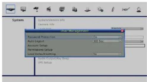
The NVR provides the option to create up to seven usernames and passwords with customized authority, excluding the preset admin account.
From the Main Menu, select System, User Management
Password Protection
Select On to enable the username and password functions listed in the Authority Setup menu, or select Off to allow free access.
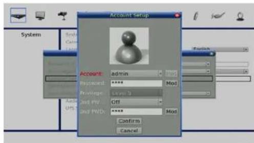
Account Setup
Use this option to setup a customized account, password, and privilege level. The account is case sensitive. The privilege levels rank from level 1 to 8, where level 8 has highest privilege. Alternatively, select Disable to stop using the account. A second password can also be specified, if required.
Note: The username and privilege level of the preset administrator account admin cannot be changed.
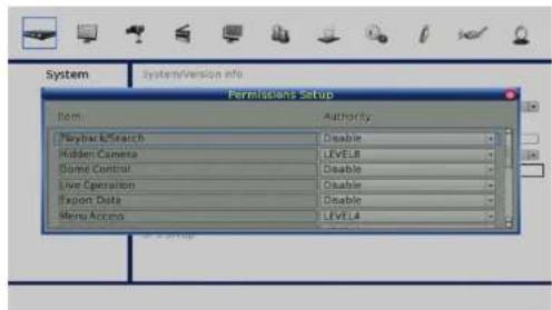
Permission Setup
Use this option to setup the authority level for accessing the functions listed in this menu. The functions include: Playback/Search, Hidden Camera, Dome Control, Export Data, Menu Access, System Setup, Monitor Setup, Camera Setup, Record Setup, Sequence Setup, Event Setup, Database Setup, Configuration, PoE Setup,and Shutdown.
The privilege levels rank from level 1 to 8, where level 8 has highest privilege. Alternatively, select Disable to allow free access.
Note: The Menu Access cannot be set to Disable.
When the account does not have authority to access certain functions, an error message will be displayed on the screen.
Load Default Setting
Select Yes to restore the default settings.
System Date / Time Setting
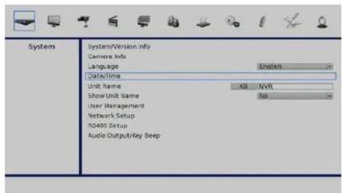
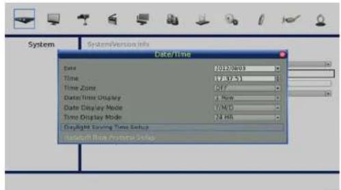
Users can set the current date, time and other OSD parameters in Date/Time menu (under System setup menu). The login account should have authority to access the System setup menu. In OSD setup menu, select System and press ENTER, then select Date/Time to access the Date/Time menu.
Set Date/Time
Set Date/Time
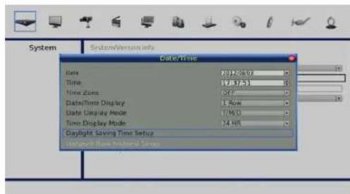
Select Date or Time and press ENTER for adjusting the settings. LEFT/RIGHT keys are used to move the cursor to previous or next field, ENTER is for selecting, and UP/DOWN are used to change the value in the selected field.
Note: The new date/time setting will only apply to newly recorded video. The date and time of previously recorded video will not be changed.
Note: If time settings have to be changed, it is strongly recommended to format the HDDs to avoid database corruption.
Date/Time Display
You can set the time to be displayed in 1 row or 2 rows. Use the UP/DOWN keys to change the setting.
Date Display Mode
This function allows you to set the display type of the date. There are three options to select from: Y/M/D, M/D/Y, or D/M/Y. Y represents Year, M represents Month and D represents Day.
Move to the date item you wish to change and press ENTER, the selected item will start blinking. Use UP/DOWN keys to change the setting.
Time Display Mode
User can set the time format to 12 HR or 24 HR. Use the UP/DOWN keys to change the format.
Daylight Saving Time
Daylight Saving Time
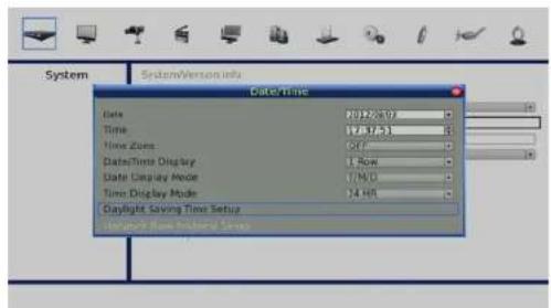
The item is for people who live in regions that observe Daylight Savings Time. Select On to enable, or Off to disable the function.
If the function is disabled, the DST Start/End time and DST Bias will be grayed out and cannot be accessed.
Note: If this function is enabled, the date/time information will be shown on the screen with a DST icon when playing back recorded video or searching video in the event list. S indicates summer time and W indicates wintertime.
DST Start/End
Use this option to set the daylight saving duration. Use LEFT/RIGHT keys to move the cursor to the next or previous field, use UP/DOWN to change the settings in the selected field.
DST Bias
This option enables you to offset the amount of time required for daylight saving time. The available options are in minutes.
Network Time Protocol Setup
Time Zone
Select Time Zone to enter the time zone. To find out the correct local time zone, please visit www.greenwichmeantime.com or refer to the adjacent diagram.
Note: The Time Zone must be set to the correct local time zone or the Network Time Protocol Setup will not be accessible.
Network Time Protocol Setup
After entering the time zone, the Network Time Protocol Setup option will appear. Select the Network Time Protocol Setup to set the NTP server. The default NTP server is time.nist.gov. A list of alternative IP addresses for NTP servers is listed below.
• 129.6.15.28
• 129.6.15.29
• 132.163.4.101
• 132.163.4.102
• 132.163.4.103
• 128.138.140.44
• 192.43.244.18
• 131.107.1.10
· 69.25.96.13
• 206.246.118.250
• 208.184.49.9
• 64.125.78.85
· 207.200.81.113
· 64.236.96.53
· 68.216.79.113
After the time server is set, select Yes for Manually Time Sync to sync the time immediately. The time sync can also be updated periodically. Select On for Automatically Time Sync, and the time will be automatically synced once every hour.

Network Setup
Dynamic DNS
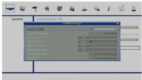
Dynamic Domain Name System (DDNS) allows a DNS name to be constantly synchronized with a dynamic IP address. This allows you to use a dynamic IP address while associated to a static domain name so others can connect to it by name.
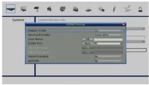
Enable this option only if you have purchased a domain name and registered with a dynamic DNS service provider. The following parameters are available for configuration:
Server Address: Select a dynamic DNS service provider from the pull-down list.
Host Name: Enter your host name. For example: myhost.mydomain.net.
DDNS Port: Enter the port for DDNS traffic
DDNS Username: Enter the username provided by your service provider.
DDNS Password: Enter the password provided by your service provider.
Submit/Update: Select yes to submit changes to the DDNS settings.
EZDDNS: Enables users to register for the host name automatically.
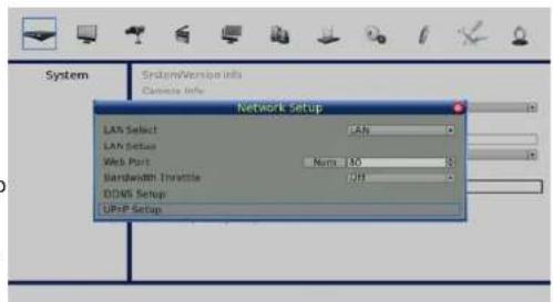
UPnP Function
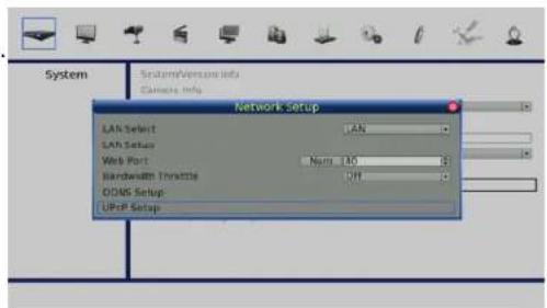
UPnP is the abbreviation for Universal Plug and Play, which is a technology that integrates a universal protocol for widespread plug-and-play devices to ease the network implementation. When a PC and the NVR have both installed the UPnP function, the PC can automatically recognize the NVR in the same local area network.
The advantage of this is that PCs can connect to the NVR via the remote control software by directly clicking on the icon representing the NVR in My Network Places folder.
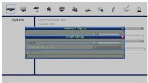
UPnP NAT Traversal Function
The UPnP NAT traversal function helps to automatically configure router settings where the NVR connects to the internet via a router.
When a PC connects to an NVR in a different local area network, a real IP address and corresponding port number are required. Where the NVR is behind a router, communications between the PC and the NVR will need to be transmitted via the router. The router will need to have port mapping (forwarding) setup before images from the NVR can be remotely viewed on the PC. For each individual NVR, this setting would need to be done on an individual basis.
Fortunately, if the NVR has UPnP NAT traversal function enabled, these settings can be made automatically. Select Yes in the UPnP setup menu to allow automatic UPnP NAT traversal.
Monitor Menu
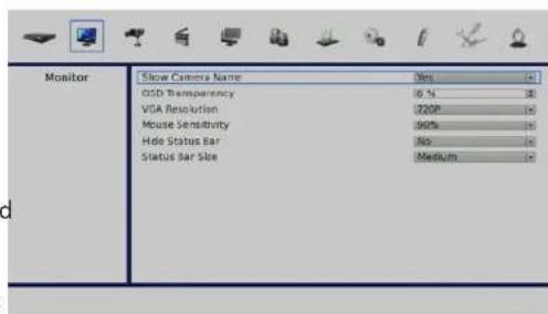
The Monitor menu allows you to configure how the various display features appear.
natural_image
Illustration of various electronic devices including a robotic arm, gear, hard disk, alarm clock, monitor, and camera (no text or symbols on devices)Section 4: Advanced Configuration
Show Camera Name: Click on the buttons to pan and tilt the lens of selected dome camera.
OSD Transparency: Choose a percentage value to determine the opacity of the On Screen Display.
VGA Resolution: Select the output resolution appropriate for the connected display.
Mouse Sensitivity: This setting will adjusts the speed which a connected USB mouse cursor will move across the screen.
Hide Status Bar: Turn the Status Bar on or Off.
Status Bar Size: Select the size of the Status Bar.
Camera Menu
This section details the options available for connecting and configuring IP cameras.
natural_image
Collection of technology and security icons including a camera, gear, monitor, and computer (no text or symbols on objects)Section 4: Advanced Configuration
When an IP camera is connected using the PoE ports, settings for that cameras will be automatically retrieved if the PoE PnP function is enabled.
Note: Go to PoE Setup PoE PnP to enable the PoE PnP function.
Note: If the IP camera is already activated, the options Device Search, Hostname/IP, Connection Setup, and Copy Settings will be grayed out and cannot be accessed.
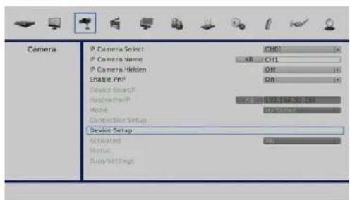
IP Camera Name
Use this option to enter the name of the IP camera to be shown on the monitor.
IP Camera Hidden
If you want to hide the feed from an IP camera, select On.
Note: the display in the remote monitoring software will also be hidden. Select Off to restore the live image to be shown on the monitor.
Device Search
Select this option and press ENTER to automatically search for IP cameras installed on the same LAN as the NVR. If the IP cameras are ONVIF compliant devices, Brand Name/Onvif will be shown under the Brand column.
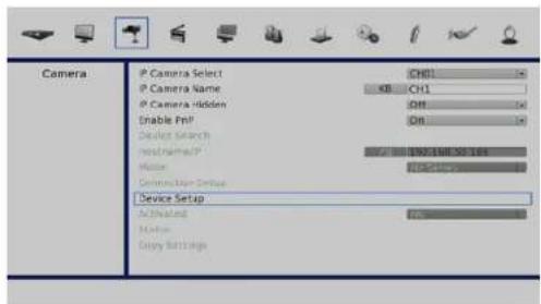
Hostname/IP
Access this item to enter the hostname or IP address of the IP camera, for example 192.168.1.123.
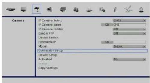
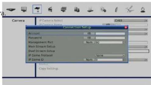
Connection Setup
Enter Connection Setup to configure the connection and data transmission settings for a connected IP Camera.
Note: You will need to set Enable PnP to Off to access all the configuration options.
Account/Password
Use these two options to enter a valid account name and password of the connected IP camera.
Management Port
Use this option to set the default port of the IP camera.
Section 4: Advanced Configuration
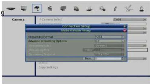
Main Stream Setup
Under this menu, users can setup configuration for the main stream. First choose the streaming format from H264, MJPEG, or MPEG4. If you need to setup a streaming index, port, and protocol manually, set Advance Streaming Options to On and select your preferred values from the corresponding menu items. Otherwise, leave Advance Streaming Options set to Off and the NVR will autoconfigure these settings.
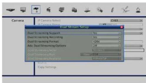
Dual Stream Setup
Under this menu, you can setup configuration for dual streams. First set Dual Streaming Support to Yes and continue through the rest of the settings. If you wish to record the dual stream, select Yes next to Dual Streaming Recording. The remaining items are the same as in Main Stream Setup.
Note: If the connected device is an IP DomeCamera, then select an appropriate IP Dome Protocol from the provided options and setup its Dome ID.
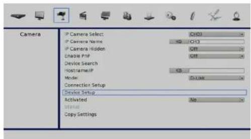
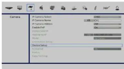
Device Setup
Enter Device Setup to configure the basic settings for an IP camera. The basic settings include the IP camera's product name, image quality, and image adjustment. Set the item Apply to Yes to apply the changes.
Note: The Device Setup menu may have fewer or more menu items according to different IP camera models.
Activated
Select Yes to activate the connection to the IP camera. To deactivate the connection, select No .
Note: Once the connection to the IP camera is activated, menu items Device Search, Hostname/IP, Connection Setup, and Copy Settings will be grayed out and cannot be accessed.
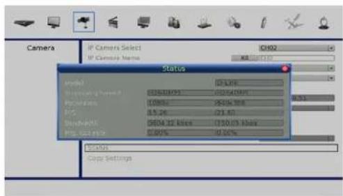
Status
After the connection to the IP camera is activated, users can check the connection status.
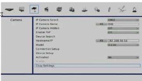
Copy Settings
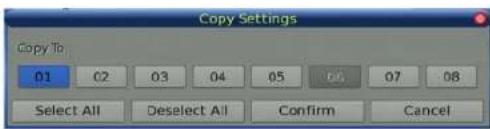
This item allows users to copy the settings set on the currently selected IP camera to any other IP cameras. Enter this menu and select one or more cameras to copy the settings to. Then select CONFIRM to apply the settings.
Note: If an IP camera is already activated, it will be greyed out and cannot be selected.
Record Menu
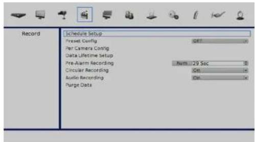
The Record setup menu allows users to set the recording quality, recording schedules, and other recording parameters. In the Main menu, move the cursor to Record and press ENTER
Record Schedule / Quality Setting
Schedule Setup
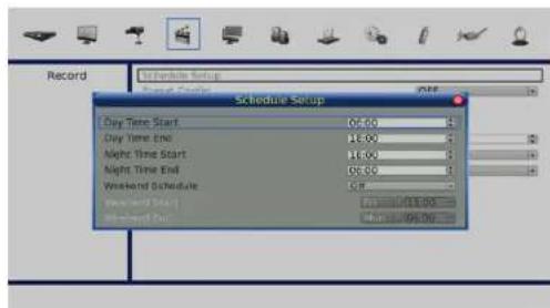
The Schedule Setup is used to set the day time, night time, or weekend recording schedule. Select Schedule Setup from the Record setup menu and press ENTER to make appropriate changes of the start time of Day and Night Time using Direction keys.
Press ENTER to confirm the settings or ESC to cancel.
If a weekend recording is required, select On to enable the Weekend Schedule in advance and then set the Weekend Start/End time.
Press ESC to return to previous page.
Preset Record Configuration
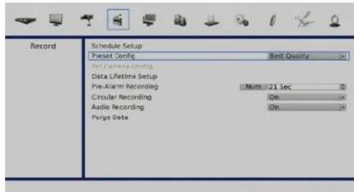
The Preset Config is used to select the preset recording quality and frame rate. In normal circumstances, it is strongly recommended to set the preset configuration as Best Quality.
Per Camera Configuration
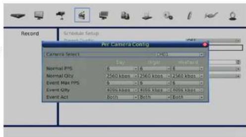
This function is used to set the Day/Night/Weekend PPS (Picture per Second) and Quality for each channel. The Preset Configuration must be set to OFF for accessing these schedules.
First, select the Camera required for configuration. The image and recording settings from the selected camera will be shown on the screen.
Move the cursor using Direction keys and press ENTER to select an item.
Change the value using UP/DOWN keys.
Press ENTER to confirm the settings or ESC to abort.
Press ESC to return to Record setup menu.
Record Event Video Only
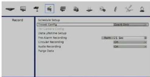
If the NVR is required to record only in response to a trigger, follow the steps below:
Enter the OSD setup menu with an account with appropriate authority.
In the OSD setup menu, select Record menu. Move the cursor to the item Preset Config, and select Event only.
Refer to "Preset Record Configuration" on page 54, Section Preset Record Configuration for further information.
Data Lifetime Setup
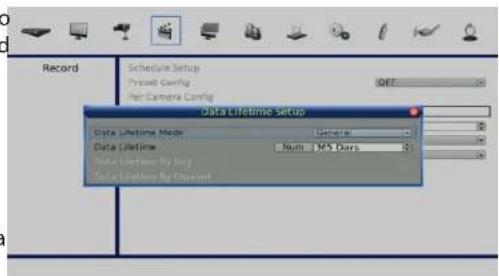
Data Lifetime indicates the duration that a video is saved and recallable in the HDD. Only video recorded within Data Lifetime will be displayed on the screen and played back. Video recorded outside of Data Lifetime will be hidden and cannot be retrieved for playback.
Note: To play back a video exceeding the data lifetime, please extend the duration until the recording data/time of the video is included.
Data Lifetime Mode
This item allows the user to choose preferred data lifetime mode. There are three types of data lifetime mode: General, By Day, and By Channel. When a specific mode is selected, further settings of the other two items below will be grayed out and cannot be accessed.
Data Lifetime
When data lifetime mode is set to General, this item will be accessible. Press ENTER to select this item and press UP / DOWN keys to set the data lifetime. The value ranges from 1 to 365 days. Alternatively, select 0 to disable this function.
Data Lifetime By Day
When data lifetime mode is set to By Day, this item will be accessible. Enter this menu and users can setup data lifetime of each weekday independently. The value ranges from 1 to 365 days. Alternatively, select 0 to disable this function.
Data Lifetime By Channel
When data lifetime mode is set to By Channel, this item will be accessible. Enter this menu and users can setup data lifetime of each channel independently. The value ranges from 1 to 365 days. Alternatively, select 0 to disable this function.
Pre-Alarm Recording
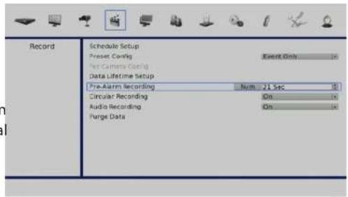
This options enables the setting of a recording duration before an alarm trigger is received. The pre-alarm recording function aims to allow users to playback video of a complete event. This enables you to playback video recorded from immediately before the alarm is triggered.
When an event is triggered while normal recording is in effect, the unit will start copying the pre-alarm and the post-alarm video to the event video. The pre-alarm duration can be set from 0 to 70 seconds. The quality of the pre-alarm video is the same as the quality setting for normal record video; and the quality of the post-alarm video is the same as the quality setting for event record video.
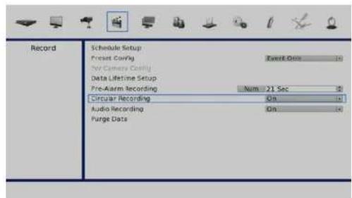
Circular Recording
You can choose to record video in either a circular mode or in a linear mode. If circular mode is selected, the NVR will store new video overwriting the oldest recordings.
Alternatively, if linear mode is selected, the NVR will stop recording when the HDD is full. In the meantime, the internal buzzer will start beeping and an alert icon will be shown on the status bar to inform users that the disk is full.
From the Record setup menu, move the cursor to Circular Recording and press ENTER, then select ON/OFF using the UP/DOWN keys.
Audio Recording
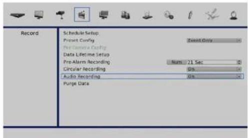
This option allows you to enable or disable the Audio recording function of the unit. When it is set to On, audio input is recorded and saved with the video. When it is set to Off, audio is not recorded.
Purge Data
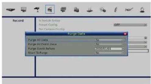
This option is used to delete the Normal or Event video recordings. In Record setup menu, move the cursor to Purge Data and press ENTER.
Purge All Event Data
Use this option to delete all video events from the database(s). Use the UP/DOWN keys to select Yes and start the deletion by setting Start To Purge to Yes.
Purge Event Before
Use this option to delete video events from before a specific date. Use the LEFT/RIGHT keys to move the cursor to next or previous field, ENTER to select the item and UP/DOWN to adjust the value.
Start To Purge
After the videos to be deleted are selected, set this item to Yes to start the deletion or choose No to cancel.
Sequence Menu
This section describes sequence mode using the Main Monitor. The sequence functions can avoid manual backtracking and provides more flexibility while monitoring recordings. Automatic sequence functions can be used in any of the viewing modes. Select a viewing mode and press SEQ to toggle the automatic sequence. Press SEQ again to stop.
natural_image
Illustration of various electronic devices including a monitor, keyboard, gear, and power switch arranged around a central screen (no text or symbols on devices)Section 4: Advanced Configuration
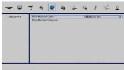
Main Monitor Dwell
Use this option to determine how long a camera will rest at a pre-determined position. Use the UP/DOWN keys to select a value and press ENTER to confirm the selection.
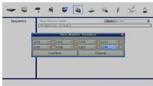
Main Monitor Schedule
Use this option to determine the order in which the main monitor will display the camera channels. The channel at the left of the top row is the first to be displayed. The channel on the right of the bottom row is the last.
Event Menu
This section outlines the options of for event based recording, you can create up to 3 event sets with their own settings.
natural_image
Illustration of various electronic and mechanical components arranged around a central 'Event' label (no other text or symbols)Section 4: Advanced Configuration
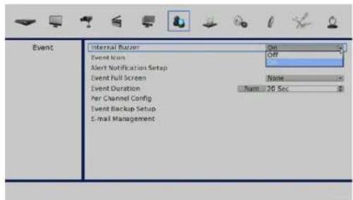
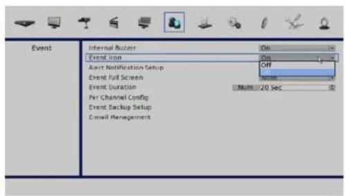
Internal Buzzer
Use this option to toggle the NVR's internal Buzzer On or Off.
Event Icon
Use this option to toggle the Event Icon notification on the Status Bar On or Off.
Section 4: Advanced Configuration
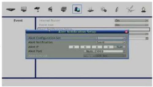
Alert Notification Setup
Use this option to configure the Event Notification parameters.
The Configurable parameters are:
Alert Configuration Set: Create up to 3 sets of event which will trigger notification.
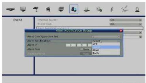
Alert Notification: Select the type of events which will trigger notification.
Alert IP: Enter the IP address which will receive the event notification alert.
Alert Port: Enter the Port at the IP address which will receive the event notification alert.
Alive Interval: Use this option to determine how long a notification should remain active.
Section 4: Advanced Configuration
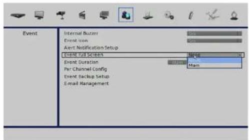
Event Full Screen
Use this option to determine if an event should be shown on the Main Display.
Event Duration
Use this option to determine how long an event should be recorded.
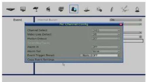
Per Channel Config
This option enables a user to specify parameters for event notifications in a granular fashion on an individual channel basis.
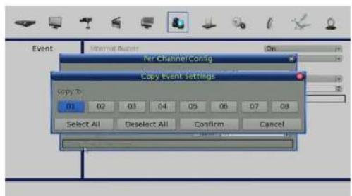
Copy Event Settings
This option to enables a user to copy the settings previously configured to another.
Section 4: Advanced Configuration
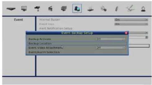
Event Backup Setup
Use this option to configure the Event Back up parameters.
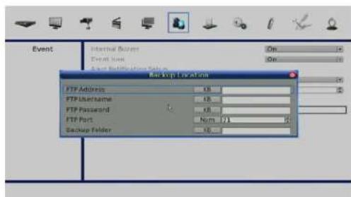
Backup Location
This feature enables you to configure automatic back up of recorded video to an FTP site.
Event/Alarm Selection
This option to enables a user to which type of events and alarms will be recorded to back up.
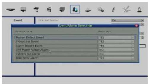
Section 4: Advanced Configuration
E-mail Management
This feature enables you to configure the parameters for automatic E-mail notification.
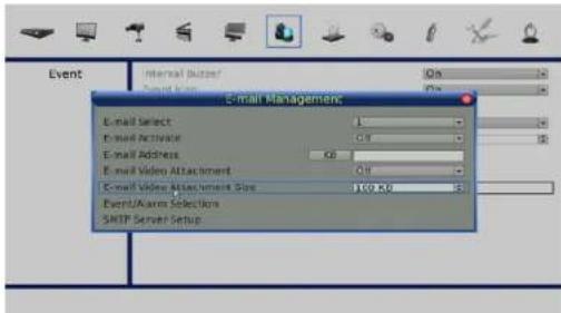
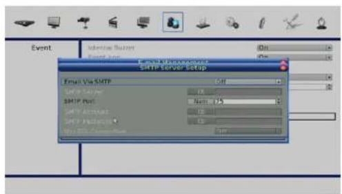
SMTP Server Setup
Enter the configuration for the target e-mail server account.
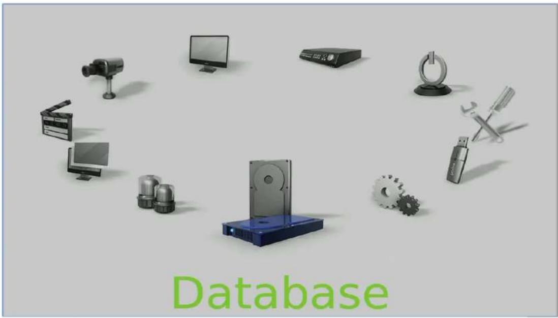
Database Menu
This section outlines the user configurable options for the NVR's Disk and Data management.
natural_image
Illustration of various electronic devices including a hard disk, camera, monitor, keyboard, and gear (no text or symbols on devices)Section 4: Advanced Configuration
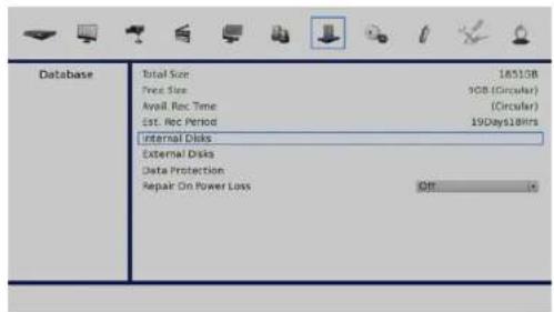
Total Size: Displays the total size of the Internal Hard Disk(s)
Free Size: Displays the disk space available for recording, and the recording mode.
Avail. Rec. Time: Displays the amount of time left in the space available for recording.
Est. Rec. Period: This is an estimate of the total amount time that can be recorded on the space given.
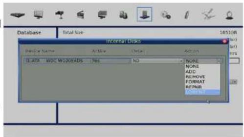
Internal Disks: This option allows the user to add, remove, format, repair and low level format internally installed disks.
External Disks: This option allows the user to manage externally attached disks.
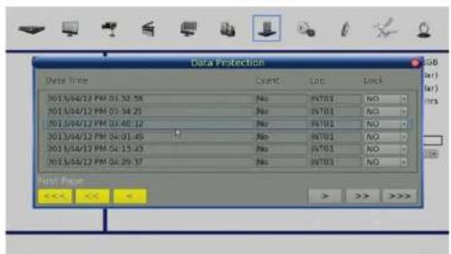
Data Protection: This option enables the user to manage the stored data records individually.
Repair on Power Loss: See "Repair on Power Loss" on page 68 for more detail on this function.
Repair on Power Loss
If the NVR finds a file system error while recording, the NVR will reboot and an HDD auto scan will be initiated. If the auto scan fails, the HDD will need to be formatted.
Note: If you wish to initiate HDD auto scan function following an abnormal power loss, enter the OSD setup menu via an authorized account and access Database to set Repair On Power Loss to On. An HDD auto scan will be initiated every time the NVR powers on following a power loss or if there is file system error.
The following options are available for the auto scan process.
Skip Auto Scan: During the scanning process, users can press any key to skip the process.
Time Expired: If the scanning exceeds a predetermined period of time (3hrs for 1TB HDD, 6hrs for 2TB HDD, etc), the scanning process is treated as failed and is automatically terminated. The NVR will reboot.
Format HDD: If the scanning process has failed, users will be prompted to confirm a format of the HDD marking the bad sectors. After confirmation, login of an authorized account is required if password protection is enabled. If users select cancel or do not respond within 5 minutes, the HDD with the error will be marked as a NG HDD. A NG HDD will not be counted as a part of the NVR's database and will sit idle.
Recover NG HDD: Enter the OSD setup menu via an authorized account and access Database. Then select Internal Disks and find the NG HDD from the list. Under Action column, select Format to format the NG HDD. Then select Add to add the formatted HDD to the database.
Configuration Menu
The Configuration setup menu enables you to review you current configuration and import or export settings as required.
natural_image
Collection of 3D icons including cameras, monitor, keyboard, gear, and hardware components arranged around a central gear symbol, with the word 'Configuration' at the bottom (no other text or symbols)Section 4: Advanced Configuration
Load Factory Default
This option will reset the NVR to its factory preset condition.
Import Config, Export Config
Importing & Exporting configuration settings can help you configure multiple NVRs quickly or help to quickly reconfigure a unit that has been reset tofactory defaults.
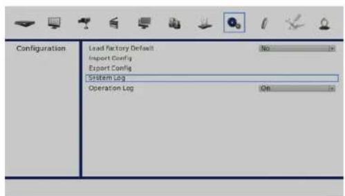
System Log, Operation Log
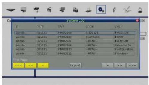
Select System Log or Operation Log and a list of system, operation logs will be displayed on the screen. You can export the log as a data file to an external storage device.
Connect a USB storage device and click on Export (or press COPY key) to export the system log file to the USB storage device.
Note: a digital signature file will also be exported.
Also under the Configuration setup menu, set Operation Log to On and operation logs will begin to be recorded in the system log. Alternatively, set to Off and operation logs will not be part of the system log.
Note: External disks must be formatted as FAT32.
Export Menu
The following section will explain how to export video through the OSD setup menu and through the function keys on the front panel, respectively. Note: that the system log will keep records of all video exported, including duration, start time, and end time.
Export Video
Make sure an external storage device is available and connected to the appropriate port for video export.
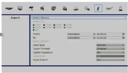
From the Main menu, select Video Export and press ENTER.
The exported video will be named by the exporting date and time, and classified by event type. Recorded video will be exported into four files if a digital signature is required (*.gpg, *.avi (or *.drv), *.sig and readme.txt)
Note: The Video Export menu will only allow authorized accounts to export video with a digital signature.
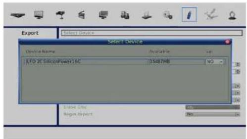
Select the External Device
The available external devices for exporting video will be listed by name and free size in the Select Device menu. The NVR only supports the EXT3 file system. If an external HDD will be connected to the unit, ensure the format of the HDD is EXT3.
Device Name
Shows the name of the available device.
Available
Shows the free space of the available device.
Select
Select Yes to set it as an export destination, or No to cancel.
Select Video for Exporting
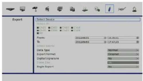
Select video from desired channel(s) with specific date / time and/or event(s), and set the item Begin Export to Yes to start exporting. Following are the items for selecting video.
Select Channel
Select the channel to export. Move the cursor to the desired channel using LEFT / RIGHT keys, select or de-select a channel by pressing ENTER.
From / To Time
The items are used to set the time which data export begins and ends. Movethe cursor using LEFT / RIGHT keys, and press ENTER to select the date /time items; adjust the selected date and time value by UP / DOWN keys.
Select Events
Select this item to display the event list. Move the cursor to scroll through the event list and press ENTER to select event(s) to be exported.
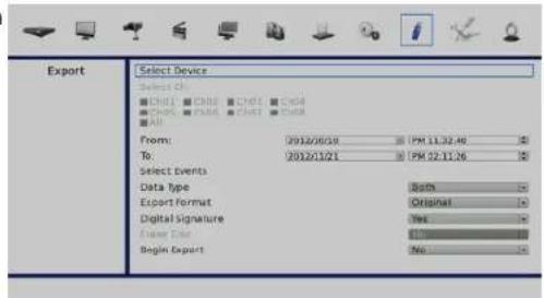
Data Type
The item is used to select exporting video type. The options are Normal(export normal video only), Event (export event video only) and Both (export both normal and event video).
Export Format
This item is for selecting exporting video format. The options are DRV, AVI, and Original. The DRV and AVI files are compressed video files while the original files are raw data of the unit's recorded video.
The DRV and original files can only be played back with the remote monitoring software and playback software, and multiple cameras video can be played back from one file. The AVI files can be played back with Windows Media Player. Note that if multiple channels are exported for AVI files, each channel is exported to a separate file.
Digital Signature
Users can export video with or without a digital signature. Set this item to Yes to export with the signature file, or No to export without it. Each recorded video with digital signature will be exported into four files, including *.gpg, *.avi (or *.drv), *.sig and readme.txt. The *.gpg file name is as the last eight MAC (Media Access Control) address of the unit.
Make sure that an external storage device, such as a USB Hard Drive is available and connected to the appropriate port for export. For more information on verifying a digital signature, see "Verify Digital Signature" on page 91.
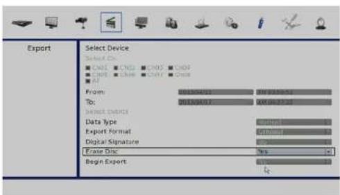
Erase Disc
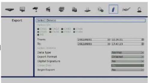
This function is used to remove data found on a DVD+RW disk prior to exporting new information to the drive. Select Yes and press ENTER to start deleting data.
Note: this option is only available when a re-writable DVD drive is attached.
Aux Menu
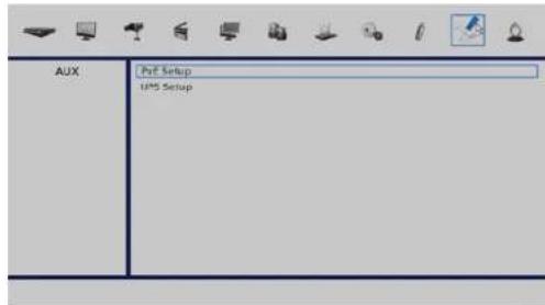
The Aux menu enables user to configure PoE and UPS settings.
natural_image
Collection of industrial and hardware icons including gears, wrench, computer monitors, and lockers arranged around a central 'AUX' label (no readable text or symbols on icons)Section 4: Advanced Configuration
PoE Setup
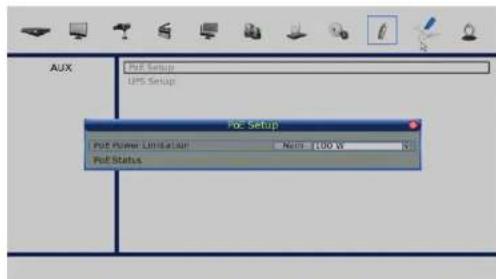
Use this option to view and configure the NVR's PoE settings.
Note: Setting the PoE Limitation too high or too low will result in unreliable performance.
UPS Setup
Use this option to configure the settings for your UPS.
Shutdown Menu
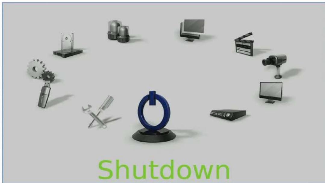
If the NVR must be shutdown for any reason, please follow the proper shutdown and power on procedures to avoid damaging the NVR.
Section 4: Advanced Configuration
To Power On the Unit:
Check the type of power source before plugging in the power cord to the NVR (the acceptable power input is between AC110V\~AC240V), and power on the unit using the power key on the front panel.
The color bar and system checking information will be shown on the monitor and then disappear when the unit has been completely powered up.
To Restart / Shutdown the Unit:
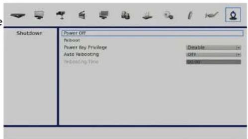
Press MENU and input the username and password to access the OSD setup menu. Select Shutdown in Main Menu and press ENTER to enter the Shutdown menu.
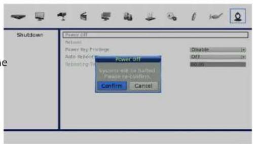
Power Off
Select this item to shut down the unit. Do not remove the power during shut down until the message You can safely turn off NVR now! displays.
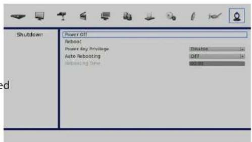
Reboot
Select this item to reboot the unit. The color bar and system checking information are displayed on the monitor until the unit is completely restarted.
Power Key Privilege
This option allows users to define quick shutdown actions following a long press of the Power key. Auth will require login of authorized account when enabled, Confirm will require confirmation before quick shutdown, Direct will directly shutdown the NVR, and Disable will disable quick shutdown function.
Auto Rebooting
The NVR can be set to reboot automatically once a day/week at predetermined time for routine maintainence. Select Off to disable the auto rebooting function
Rebooting Time
If the auto rebooting function is enabled, select a desired time to perform the auto rebooting function.
Using the Web Interface
The NVR's built-in Web UI utility is designed to allow you to easily access and configure your NVR. The software is a browser-based application. Using this utility, users can view live and recorded video, and to configure the NVR remotely via a LAN, WAN or Internet using any personal computer. The connected PC will automatically download the browser plug-ins from the NVR. Simply enter the NVR's IP address in the address bar in to a browser. See "Change Internet Settings" on page 80 for more information.
The main categories for configuration are located on the menu tabs at the top of the page. These categories include:
• Live Video - Shows the live video of network cameras and controls PTZ functions.
- Playback - Displays recorded video and exports snapshots or video.
- Setup - Contains the NVR setup wizard, as well as the LAN configuration settings, camera search, camera settings, recording schedule, auto backup, event settings, time and system settings, and device settings.
- Maintenance - Contains the Administrator account configuration options, Hard Disk management options and RAID configuration options. System configuration, backup, and restore functions are also available.
- Status - Contains system, NVR, and event logs.
Note: The Menu function allows users to remotely access the NVR's OSD setup menu functionality, with some limitations.
Refer to the previous sections for instructions on configuring the NVR.
Web UI System Requirements
Minimum Requirements
| Personal Computer | Intel® CoreTM Duo 2.4GHz |
| RAM 1GB | |
| Hard Disk Drive 20 MB for software installation | |
| Operating System Windows XP | |
| Web Browser Internet Explorer version 8.0 | |
| Monitor 1024×768 with 16-bit color | |
| Network Card 10/100 Mbps | |
Suggested Specification
| Personal Computer | Intel® CoreTM i7-2600 3.4GHZ |
| RAM 4GB | |
| Network Card 10/10 | 0/1000 Mbps |
Web UI Setup
Change Internet Settings
Before using the Web UI, please check the IP address of the NVR. To check the IP address, press MENU key on the unit and enter username and password to access the OSD setup menu. Select System, Network Setup, then LAN Setup to check the IP.
Start Internet Explorer by clicking on the desktop icon, or by using the Start menu to access it.
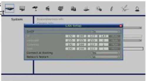
The PC needs to be set to accept ActiveX plug-ins. Please follow the steps to set the Internet security settings appropriately.
Note:
Internet Explorer provides the ActiveX component that is required when using the remote monitoring software.
Select Tools from the main menu of the browser, then Internet Options, and then click the Security tab.
Select Trusted sites and click Sites to specify its security setting.
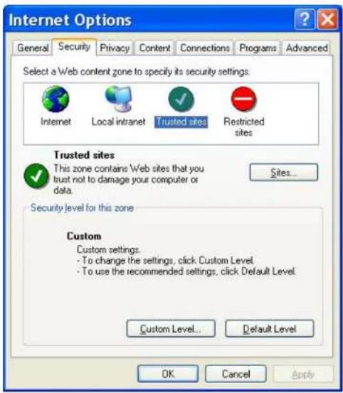
Section 5: Remote Operation
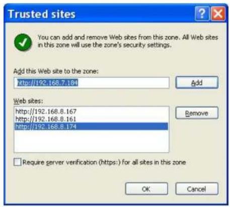
In the Trusted sites dialog:
Uncheck Require server verification (https:) for all sites in this zone.
Type the IP address of the NVR unit to be configured and click Add to add this web site to the zone
Click OK to confirm the setting and close Trusted sites dialog.
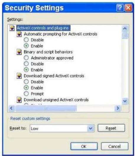
In the Security Level area, click Custom Level.
Under ActiveX controls and plug-ins, set all items to Enable or Prompt.
Click OK to apply the setting and close the Security Settings screen.
Click OK to close Internet Options dialog.
Now the installation can continue to the next step.
Install Web UI Browser Plugins
Start Internet Explorer by clicking on the desktop icon, or by using the Start menu to access it. Enter the IP address of the NVR in the address bar at the top of the browser.
This will initiate the installation of the browser plugins required for the Web UI. The IP address of the NVR can be saved as a Favorites item in the Internet Explorer to enable easy access in the future.
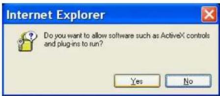
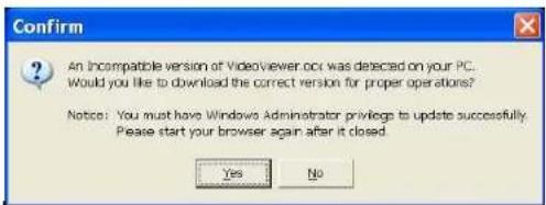
The ActiveX controls and plug-ins dialog will show twice for confirmation; click Yes to accept ActiveX plug-ins.
The Web UI plug-ins will be downloaded and installed on the PC automatically when the connection is successfully made.
Note: Do not enter any leading "0" characters in the address, for example, "192.068.080.006" should be entered as "192.68.80.6". If the default trigger port 80 is changed into another one, take port 81 for example, the IP address should be entered as "192.68.80.6:81".
A version check starts to verify whether the Web UI software was installed already, and also check if the version is the same as that stored in that particular NVR. This process may take up to 30 seconds.
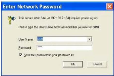
When the browser plugins are completely downloaded and installed, the Login Screen will be displayed.
Log in/Log off
Log in using the same account details previously setup in "User Management" on page 36.
One preset account admin and up to four other accounts can access a NVR at the same time.
Note: if the admin account is currently accessing the NVR's OSD setup menu via front panel of the NVR, then the admin account at the remote monitoring site cannot change the settings at the same time. The admin account at the NVR side has priority.
The following steps demonstrate procedures to connect and login to the NVR.
Start the remote monitoring software by entering the IP Address of the NVR in the Address bar of the browser. Alternatively, click on the Favorite entry for the unit (if the IP address of the unit has been set).
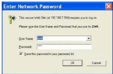
Enter the Username and password. The login username and password can be saved to ease future logins. The default username and password is admin/1234.
Click OK to log in to the NVR. The process may take a few seconds.
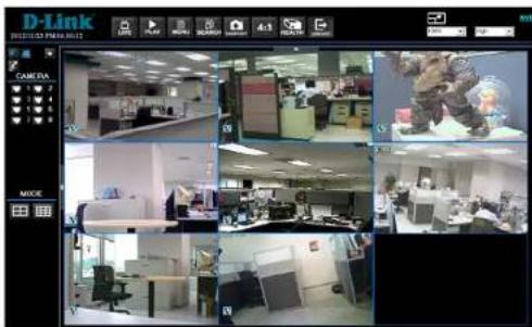
When the connection is made successfully, the main window will display live video of the attached cameras. When the web browser is closed, the remote system is logged out and disconnected from the NVR at the same time.
Firmware Upgrades
If a new version of the Web UI firmware is available on the NVR, the user will be prompted while accessing the unit. Click Yes to accept the upgrade and follow the on screen instructions.
Start Internet Explorer again and enter the IP address of the NVR in the Address bar of the browser; or if the unit address is set as a Favorite site, click the Favorites entry for the unit.
When the software is completely downloaded and installed, the Login Screen will be displayed.
Web UI Basic Operation
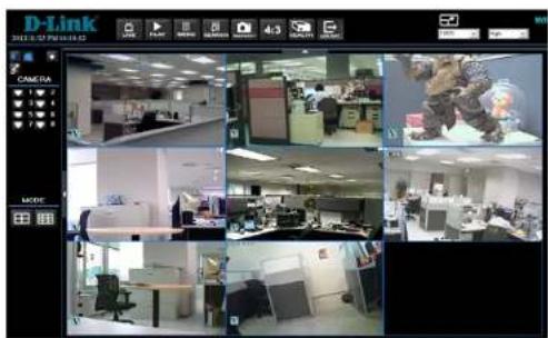
When a NVR is successfully connected, the main window of the Web UI will be displayed. Please reference "Basic Operation" on page 20 for an overview of the features available. Functions specific to the Web UI will be described in the following sections.
Live Video
View live video from the cameras attached to the NVR by clicking the Live button on the main window toolbar. Choose a desired display mode – full-screen, 4-windows, 9-windows, 16-windows, and 20-windows – after the live images of the NVR are displayed on the main window. When a dome camera is connected and viewed in single channel full-screen mode, the dome camera control operation can be accessed. To choose desired display mode and to operate dome camera control, refer to the following sections.
Select Display Mode
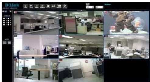
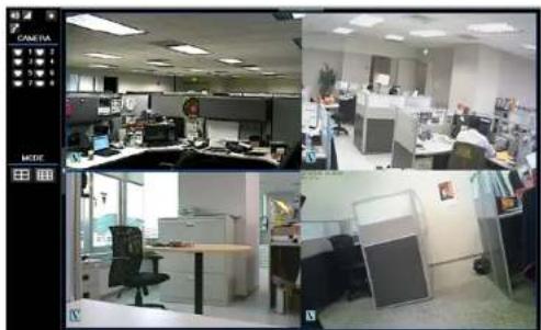
To choose the number of camera feeds to be displayed in the main window, click one of the display buttons in the MODE section of the left toolbar. Available selections are 4, and 8 (9-1) camera display grids. To view a specific feed in full-screen, either double-click on the preferred grid, or click on the corresponding CAMERA button in the left toolbar.
Note: To maximize the video viewing area the main/top toolbar, and the left/side tool bar can be hidden.
natural_image
Four-panel office interior view showing cubicles, desks, and workstations (no visible text or signage)Operate Cameras with Dome Control
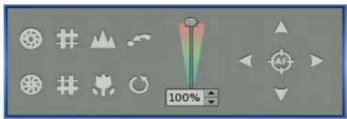
Auto Focus (A.F.): Click on it and the focus of the camera will be automatically adjusted to show a clearer image.
Set/Go Preset & Run Tour: The remote monitoring software allows its users to store up to 255 preset points according to the allowance of the supported dome cameras.
Use Direction buttons to pan/tilt dome camera to an appropriate position. Then click this button, select Set Preset and choose a preferred number from the pull-down list. The preset point is named as the selected number.
Click this button, select Go Preset and choose a preferred number from the pull-down list to call the preset point for viewing.
Click this button, select Run Tour and the dome camera will start the tour set previously at the dome camera side.
Dome ID (ID): Click for changing the dome ID and protocol. Proper authority is required to access this function.
Focus +/-: Use to adjust the camera lens to focus on objects for a clear view. Click on Focus + to focus near or Focus - to focus far.
Iris +/-: This item is used to open and close the iris to let more or less light into the camera. Click on Iris + to open iris or Iris - to close iris.
Zoom +/-: Users are able to zoom-in or zoom-out using the adjusting buttons. Zoom-in to enlarge a certain area and zoom-out to view more area.
Direction Button: This button is used to pan and/or tilt the dome camera. Click the arrows in the directions to be viewed.
Digital Zoom of Camera Display
Users can view the camera zoom-in images via the digital zoom function.
Right click on any preferred camera grid, in any kind of display mode, and select the digital zoom item to switch on the function. Users then can easily control zoom in/out via mouse scroll wheel.
Move the scroll wheel away from users to zoom in and move toward the users to zoom out. On the upper left-hand corner will show zoom-in magnification.
The maximum magnification is x7. Also on the lower Right-hand corner will display the position of current viewing area (shown as an inner white rectangle) comparing with the original screen (shown as an outer rectangle frame). In addition, the viewing area can be dragged and moved by LEFT clicking and holding the mouse while moving.
Note: This function will use up a lot of CPU resources. It is recommended not to open too many programs at the same time to avoid crash of CPU.
Manually Trigger Relay Output Devices
The Web UI allows users to manually trigger relay output devices while monitoring at the remote site. RIGHT click on any camera grid and select relay out A, B, or C to manually trigger any of them. This is especially convenient when users wishes to trigger any relay output devices while monitoring at the remote site.
Instant Recording
Instant Recording function allows users to record video to the PC by one click.
Note: The Audio function is set to OFF as the default setting.
Record Video Instantly
Follow the steps to start recording instantly:
Click on the Instant Recording button.
Select the destination folder to save the video.
Click on the Instant Recording button again to stop recording.
Note: The instant recording video will be saved as *.drv file.
Playback Instant Recorded Video
Follow the steps to playback a video recorded by Instant Recording.
Click Play on main window toolbar and click Local Playback tab.
Click Open to choose a recorded file.
Click OK to start playing the recorded video.
Playback Video
The remote monitoring software allows users to either view recorded video from the NVR, or from the hard disk drive of the PC.
To access the Playback screen, click Play button on the main window toolbar.
There are three tabs in the Playback screen: Remote Playback, Local Playback, and the Verify tab. Remote Playback allows users to playback from the NVR. Local Playback enables users to playback a recorded video file stored on the hard disk drive of the PC. Verify is provided for users to authenticate if the exported video is altered. During either remote playback or local playback the NVR can simultaneously record while displaying from the PC.
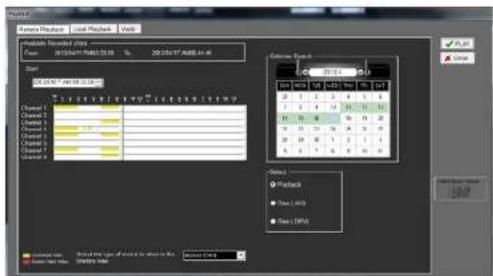
Remote Playback
The remote monitoring software allows users to either view recorded video from the NVR, or from the hard disk drive of the PC.
To access the Playback screen, click the Play button on the main window toolbar.
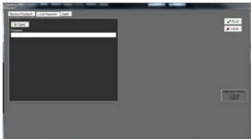
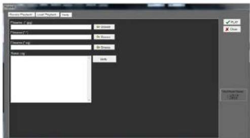
Playback Local \*.drv Files
The Local Playback tab allows users to playback *.drv video files stored in the PC's hard drive.
To playback a downloaded *.drv file from the Web UI:
Click Open and the file selection screen is displayed.
Select the *.drv video file for playback and click OK.
Click OK in the Local Playback Screen to start the playback, or click Cancel to abort.
View the video playback using the Playback controls.
To end the playback, click Live to return to live video.
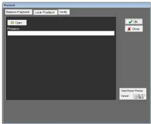
Playback Controls
When the local or remote video is being played, the Web UI is in Playback Mode. The playback controls toolbar will appear in the main window. The Playback controls are described in "Key Usage in Playback" on page 23.
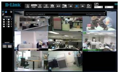
Verify Digital Signature
The digital signature aims to authenticate a video file exported from the NVR.
To verify the digital signature.
Click Play on the main window toolbar.
Click the Verify tab to display the Verify window.
Click Browse to select the *.gpg, *.avi, *.sig files respectively, which belong to the exported video to be authenticated.
Click Verify to start verifying digital signature.
The result of the verification will be sent to the Status Log field as a GOOD or BAD signature result. A GOOD signature indicates the exported clip has not been altered.
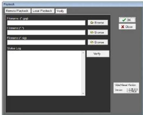
Search from Event List
Click SEARCH, the Event List appears. The list contains information about the alarm events that the unit recorded and saved. Up to 1024 events can be listed in the Event List. The Event List displays each event by its number, the date and time of the event, the type of the event (including Alarm In, Motion Detection, and Video Loss), and the camera channel where the event occurred.
To view an event video, follow these steps:
Click SEARCH button positioned in the main window toolbar. The Event List appears.
Scroll through the Event List and highlight the interested events.
Double-click on the desired event to view the event video.
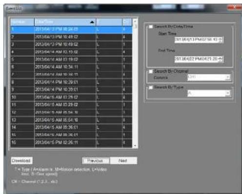
Take a Snapshot
Snapshot is a simple screen capture tool. When users click on the SNAPSHOT button, it will capture the screenshot of the window that is currently showing on the screen. Each click captures one screenshot to be saved as a JPEG file on the desktop. The snapshot file will be named as Snapshot-*.
Health Status of HDD
This function verifies HDD status of the NVR. The information items shown in the chart are described as below:
Device Name: This item shows the model name of the HDD.
Int./Ext.: This item indicates whether the HDD is an internal or external device.
Total Size: This item indicates the total size of the HDD.
State: This item indicates whether the HDD is active or non-active.
Temperature: This item indicates the current temperature of the HDD in Celsius degree.
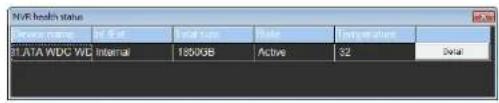
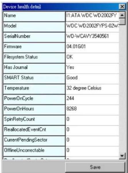
Normal and Dual Streaming
For different networks with different bandwidths, two streaming options are provided – normal and dual streaming. The preset is normal streaming. Users who are using high-speed networks, normal streaming will be a recommended choice. Depending on the HDD capacity and network usage, set the remote monitoring software to occupy high or low bandwidths.
For networks with limited bandwidth, dual streaming will be a better choice. It enables coexistence of high quality streaming at local NVR site and lower quality streaming but faster transmission for the remote monitoring site. To select dual streaming, click on the bandwidth icon and the icon will change color. Then users can furthermore choose different bit rates to adjust for the best displaying quality.
Web UI Advanced Operation
Users can remotely access the full functionality of the NVR using the Menu button on the Web UI.
Click on the Menu button and the Configuration panel will appear.
Refer to the relevant earlier sections of this manual for detailed explanations of the functions.
Remote Firmware Upgrade/Remote NVR Reboot
Users can remotely perform a firmware upgrade or reboot the connected NVR.
Software Upgrade via Internet
Click the MENU button in the main window toolbar. A Configuration window will be displayed. Go to System Setup System/Version Info and the menu is as shown below. Then click on the Execute button and locate the upgrade file "*.tar" or files "*.tgz & *.md5" to start remote software upgrade.
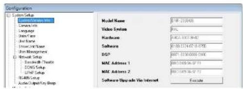
Remotely Reboot
Also from the Configuration window, access the Shutdown menu as shown below. Then click on the Execute button to remotely reboot the NVR.
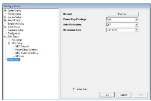
Firmware Troubleshooting
If the server requests to upgrade the firmware every time the NVR is connected follow the steps below to delete the temporary internet files.
Select Tools from the main menu of the web browser, then Internet Options, and then click the General tab.
Click the Delete Files button in the Temporary Internet Files field; the Delete Files screen displays as below.
Check the Delete all offline content box and click OK.
Enter the IP address of the NVR to make the connection again.
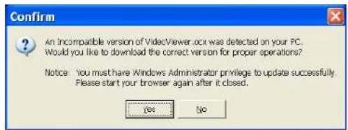
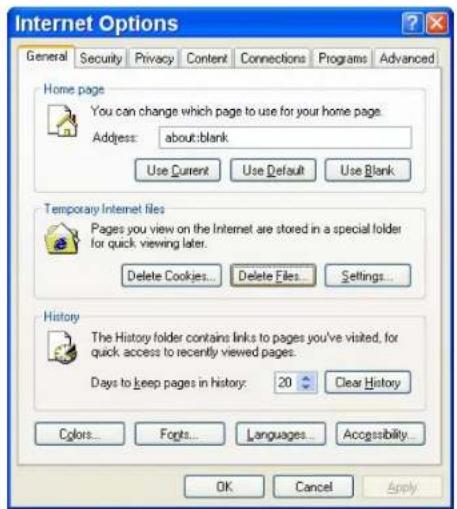
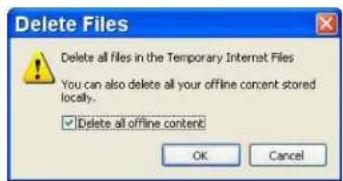
Appendix A: Recommended HDDs
| Brand | Model Name | Model Number Size | |
| WD | Caviar Blue | WD10EALX 1.0TB |
NOTE: After a HDD is successfully installed, users will see a number shown in front of the device name when retrieving internal disks information in the OSD setup menu via Database, Internal Disks. The number represents the SATA port that the HDD is connected to.
DI/DO Specifications
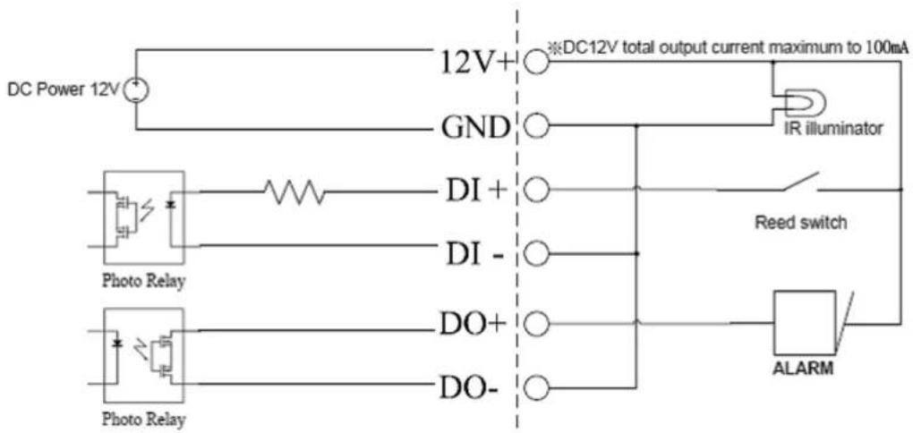
flowchart
graph TD
    A["DC Power 12V"] --> B["12V+"]
    B --> C["GND"]
    C --> D["IR illuminator"]
    E["Photo Relay"] --> F["DI+"]
    F --> G["DI-"]
    G --> H["DO+"]
    H --> I["DO-"]
    I --> J["ALARM"]
    K["Reed switch"] --> L["AND Gate"]
    style A fill:#f9f,stroke:#333
    style E fill:#ccf,stroke:#333
    style K fill:#cfc,stroke:#333
    style L fill:#fcc,stroke:#333
Technical Specifications
| General | ||
| Backup | • USB Storage Backup via NVR USB Port | • Remote Archive via Client Software |
| Playback and Recording Performance Playback: | • NTSC: 60pps at 1080P, 120pps at 720P, 240pps at 480P (camera dependent)• PAL: 50pps at 1080P, 100pps at 720P & 200pps at 480P (camera dependent) | Record: UP to 8 channels• NTSC:240pps at 1080P, 720P, 480P (camera dependent)• Pal: 200pps at 1080P, 720P, 480P (camera dependent) |
| Playback Search • Forward, reverse, step-by-step and different speed play/calendar, event & panorama | • Front panel/keyboard and mouse via usb port/remote control handset | |
| Video Compression | • H.264/MJPEG codec , JPEG for still image• Multicast streaming | • Simultaneous playback/record/live view |
| Standalone Video Output • HDMI and VGA at 1024 x 768, 1280 x 1024, 720p, 1080p | ||
| Audio Support • PCM • G.711 | ||
| External Device Interface • RJ45 port (auto MDI/MDIX) Gigabit Lan• Eight RJ45 port with PoE (IEEE 802.3at)• VGA• HDMI• DC-in jack | • e SATA• Eight alarm I/O• Eight DI/DO• Audio out | |
| HDD | • Six internal bays | • SATA I,II |
| Network | ||
| Ports | • Eight 10/100 TX IEEE 802.3at PoE Ethernet | • Auto MDIX Gigabit Ethernet Lan |
| Network Protocols | • IPV4, ARP, TCP, UDP, ICMP• DHCP Client• DNS Client• SMTP Client (SSMTP support) | • HTTP Server• PPPoE• RTP• RTSP |
| Security | • Administrator and user group protection | • Password authentication |
| System Management | |
| Remote Management • Take snapshots/video clips via web browser • Configuration interface accessible via web browser | |
| Event Management • Motion detection | • Multiple SMTP servers.• Event notification and upload snapshots/video clips via SMTP or FTP • Multiple event notification |
| System Requirements • Operating System: Microsoft Windows 7/Vista/XP • Web Browser: Internet Explorer 7 or higher | |
| Mobile Support | • iOS • Android |
| Physical | |
| Weight • 9.02 kilograms (19.9 lbs) | |
| Power | • Input: AC 100 to 240V at 50/60 Hz • Output: 5 V DC, 750 mA (via USB port) |
| Temperature • Operating: 0 to 40 °C (32 to 104 °F) • Storage: -20 to 70 °C (-4 to 158 °F) | |
| Humidity • Operating: 10% to 90% non-condensing • Storage: 5% to 95% non-condensing | |
| Certifications | • CE • FCC• CE LVD • C-Tick |
| Dimensions |  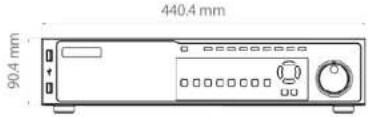 • (H) 90.4 mm (3.56 inches)• (w) 440.4 mm (17.34 inches)• (D) 450.9 mm (17.75 inches) • (H) 90.4 mm (3.56 inches)• (w) 440.4 mm (17.34 inches)• (D) 450.9 mm (17.75 inches) |
- User Manual
- Bay Network Video Recorder
- Preface
- Manual Revisions
- Trademarks
- Table of Contents
- Product Overview Package Contents
- Introduction
- System Requirements
- Features
- Comprehensive IP Surveillance Solution
- Complete Connectivity
- Fully Functional Recording
- Front Panel LED Indicators
- Hard Disk Drive Installation
- Step 1
- Step 2
- Step 3
- Step 4
- Connecting a Power over Ethernet IP Camera
- Remote Control Operation
- USB Mouse Operation
- Camera Title Alignment
- USB Keyboard Operation
- Jog/Shuttle Control
- Function Keys
- Basic Operation Viewing Modes
- Section 3: Front Panel Operation
- Digital Pan and Zoom
- Freeze Live Video
- View Recorded Video
- Key Usage in Playback
- LEFT (Reverse Playback)
- RIGHT (Fast Forward Playback)
- FREEZE
- PLAY
- Pause, Playback and Single Step Forward
- Search Recorded Video
- Search by Time
- Calendar Search
- Search and Playback with the Event List
- Panorama Search
- Search by Text
- By Text:
- By Numerals:
- Dome Control
- Set Preset Points
- Call Preset Points
- Run Dome Camera Tour
- Quick Video Export through Front Panel
- Export Event Video
- Advanced Operation System Menu
- User Management
- Password Protection
- Account Setup
- Permission Setup
- Note: The Menu Access cannot be set to Disable.
- Load Default Setting
- System Date / Time Setting
- Set Date/Time
- Date/Time Display
- Date Display Mode
- Time Display Mode
- Daylight Saving Time
- DST Start/End
- DST Bias
- Network Time Protocol Setup
- Time Zone
- Network Setup
- Dynamic DNS
- UPnP Function
- UPnP NAT Traversal Function
- Monitor Menu
- Section 4: Advanced Configuration
- Camera Menu
- IP Camera Name
- IP Camera Hidden
- Device Search
- Hostname/IP
- Connection Setup
- Account/Password
- Management Port
- Main Stream Setup
- Dual Stream Setup
- Device Setup
- Activated
- Status
- Copy Settings
- Record Menu
- Record Schedule / Quality Setting
- Schedule Setup
- Preset Record Configuration
- Per Camera Configuration
- Record Event Video Only
- Data Lifetime Setup
- Data Lifetime Mode
- Data Lifetime
- Data Lifetime By Day
- Data Lifetime By Channel
- Pre-Alarm Recording
- Circular Recording
- Audio Recording
- Purge Data
- Purge All Event Data
- Purge Event Before
- Start To Purge
- Sequence Menu
- Main Monitor Dwell
- Main Monitor Schedule
- Event Menu
- Internal Buzzer
- Event Icon
- Alert Notification Setup
- Event Full Screen
- Event Duration
- Per Channel Config
- Copy Event Settings
- Event Backup Setup
- Backup Location
- Event/Alarm Selection
- E-mail Management
- SMTP Server Setup
- Database Menu
- Repair on Power Loss
- Configuration Menu
- Load Factory Default
- Import Config, Export Config
- System Log, Operation Log
- Export Menu
- Export Video
- Select the External Device
- Device Name
- Available
- Select
- Select Video for Exporting
- Select Channel
- From / To Time
- Select Events
- Data Type
- Export Format
- Digital Signature
- Erase Disc
- Aux Menu
- PoE Setup
- UPS Setup
- Shutdown Menu
- To Power On the Unit:
- To Restart / Shutdown the Unit:
- Power Off
- Reboot
- Power Key Privilege
- Auto Rebooting
- Rebooting Time
- Using the Web Interface
- Web UI System Requirements
- Web UI Setup
- Change Internet Settings
- Note:
- Section 5: Remote Operation
- Install Web UI Browser Plugins
- Log in/Log off
- Firmware Upgrades
- Web UI Basic Operation
- Live Video
- Select Display Mode
- Operate Cameras with Dome Control
- Digital Zoom of Camera Display
- Manually Trigger Relay Output Devices
- Instant Recording
- Record Video Instantly
- Playback Instant Recorded Video
- Playback Video
- Remote Playback
- Playback Local \*.drv Files
- Playback Controls
- Verify Digital Signature
- Search from Event List
- Take a Snapshot
- Health Status of HDD
- Normal and Dual Streaming
- Web UI Advanced Operation
- Remote Firmware Upgrade/Remote NVR Reboot
- Software Upgrade via Internet
- Remotely Reboot
- Firmware Troubleshooting
- Appendix A: Recommended HDDs
- DI/DO Specifications
Brand : D-LINK
Model : DNR-2060-08P
Category : Voice recorder