
SM226S - Séparateur de signal Rane - Free user manual and instructions
Find the device manual for free SM226S Rane in PDF.


| Product Type | Signal Splitter / Mixer |
| Model | SM226S |
| Brand | Rane |
| Power Supply | 100-240 V~, 50/60 Hz, 7 W |
| Inputs | 6 x Mono Input (1/4" TRS balanced/unbalanced), 2 x Master Input (L/R) (1/4" TRS balanced/unbalanced) |
| Outputs | 6 x Mono Output (1/4" TRS balanced/unbalanced), 2 x Mix Output (L/R) (1/4" TRS balanced), 2 x Expand Out (parallel to Master In) |
| Controls | Master Input Level (-∞ to +12 dB), Master Output Level (-∞ to 0 dB), 6 x Channel Level (-∞ to +12 dB), 6 x Mix/Pan |
| Indicators | Power LED (yellow) |
| Construction | 1U rackmount (19" width) |
| Special Features | Functions as 6-channel mixer or 2-to-6 splitter; internal jumper options for custom routing; daisy-chain via Expand Out |
| Safety Compliance | FCC Part 15 Class B, Canadian ICES-003, UL listed |
| Cleaning Instructions | Clean only with a dry cloth |
| Repair Policy | No user-serviceable parts; refer servicing to qualified personnel |
Frequently Asked Questions - SM226S Rane
User questions about SM226S Rane
0 question about this device. Answer the ones you know or ask your own.
Ask a new question about this device
Download the instructions for your Séparateur de signal in PDF format for free! Find your manual SM226S - Rane and take your electronic device back in hand. On this page are published all the documents necessary for the use of your device. SM226S by Rane.
USER MANUAL SM226S Rane
IMPORTANT SAFETY INSTRUCTIONS
-
Read these instructions.
-
Keep these instructions.
-
Heed all warnings.
-
Follow all instructions.
-
Do not use this apparatus near water.
-
Clean only with a dry cloth.
-
Do not block any ventilation openings. Install in accordance with manufacturer's instructions.
-
Do not install near any heat sources such as radiators, registers, stoves, or other apparatus (including amplifiers) that produce heat.
-
Do not defeat the safety purpose of the polarized or grounding-type plug. A polarized plug has two blades with one wider than the other. A grounding-type plug has two blades and a third grounding prong. The wide blade or third prong is provided for your safety. If the provided plug does not fit into your outlet, consult an electrician for replacement of the obsolete outlet.
-
Protect the power cord and plug from being walked on or pinched particularly at plugs, convenience receptacles, and the point where it exits from the apparatus.
-
Only use attachments and accessories specified by Rane.
-
Use only with the cart, stand, tripod, bracket, or table specified by the manufacturer, or sold with the apparatus. When a cart is used, use caution when moving the cart/apparatus combination to avoid injury from tip-over.
-
Unplug this apparatus during lightning storms or when unused for long periods of time.
-
Refer all servicing to qualified service personnel. Servicing is required when the apparatus has been damaged in any way, such as power supply cord or plug is damaged, liquid has been spilled or objects have fallen into the apparatus, the apparatus has been exposed to rain or moisture, does not operate normally, or has been dropped.
-
The plug on the power cord is the AC mains disconnect device and must remain readily operable. To completely disconnect this apparatus from the AC mains, disconnect the power supply cord plug from the AC receptacle.
-
This apparatus shall be connected to a mains socket outlet with a protective earthing connection.
-
When permanently connected, an all-pole mains switch with a contact separation of at least 3 mm in each pole shall be incorporated in the electrical installation of the building.
-
If rackmounting, provide adequate ventilation. Equipment may be located above or below this apparatus, but some equipment (like large power amplifiers) may cause an unacceptable amount of hum or may generate too much heat and degrade the performance of this apparatus.
-
This apparatus may be installed in an industry standard equipment rack. Use screws through all mounting holes to provide the best support.
WARNING: To reduce the risk of fire or electric shock, do not expose this apparatus to rain or moisture. Apparatus shall not be exposed to dripping or splashing and no objects filled with liquids, such as vases, shall be placed on the apparatus.
WARNING

CAUTION
RISK OF ELECTRIC SHOCK DO NOT OPEN

To reduce the risk of electrical shock, do not open the unit. No user serviceable parts inside. Refer servicing to qualified service personnel.
The symbols shown below are internationally accepted symbols that warn of potential hazards with electrical products.
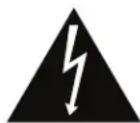
This symbol indicates that a dangerous voltage constituting a risk of electric shock is present within this unit.

This symbol indicates that there are important operating and maintenance instructions in the literature accompanying this unit.
WARNING: This product may contain chemicals known to the State of California to cause cancer, or birth defects or other reproductive harm.
NOTE: This equipment has been tested and found to comply with the limits for a Class B digital device, pursuant to part 15 of the FCC Rules. These limits are designed to provide reasonable protection against harmful interference in a residential installation. This equipment generates, uses and can radiate radio frequency energy and, if not installed and used in accordance with the instructions, may cause harmful interference to radio communications. However, there is no guarantee that interference will not occur in a particular installation. If this equipment does cause harmful interference to radio or television reception, which can be determined by turning the equipment off and on, the user is encouraged to try to correct the interference by one or more of the following measures:
- Reorient or relocate the receiving antenna.
- Increase the separation between the equipment and receiver.
- Connect the equipment into an outlet on a circuit different from that to which the receiver is connected.
- Consult the dealer or an experienced radio/TV technician for help.
CAUTION: Changes or modifications not expressly approved by Rane Corporation could void the user's authority to operate the equipment.
This Class B digital apparatus complies with Canadian ICES-003.
Realizing that in most areas there are laws against reading owners manuals, and that reading them under the blankets at night with a flashlight makes you feel stupid, we therefore provide this brief, yet legal description of how to use the SM26S just in case your batteries are low and your mother is about to come in the room.
To achieve a quick understanding of the SM26S, think of it as a six channel mixer with faders and pans only. Or think of it as a 2-to-6 channel splitter with output level controls and a mix knob (to control how much of which input goes to which output). If you get that, you may stop here as long as you know what a TRS plug is.
As a six channel mixer, MONO INPUT 1 through 6 may be placed on the Right or Left bus or both, in any amount. The respective LEVEL controls on the front serve as the mixer's faders, the adjacent PAN controls place the channel's signal into the stereo field. As an effects mixer or line level expander for a larger mixer, set up the LEVELS then adjust the PANS. The MASTER OUTPUT LEVEL adjusts the overall level of the mix at the Master Outputs.
As a splitter, place one or both input signals into the LEFT and/or RIGHT MASTER INs. Select the Input(s) to be placed at each of the six MONO OUTPUTS by rotating the MIX / PAN control to the proper position. Set the individual channel LEVEL controls for proper output level. The MASTER INPUT LEVEL control adjusts both Right and Left Input signal levels together.
SM26S Connection
When connecting the SM26S to other components in your system for the first time, leave the power cord for last. This gives you a chance to make mistakes and correct them before damage is done to anything fragile.
As you have no doubt noticed, all Inputs and Outputs on the SM26S's rear panel are 14 " connectors. The Inputs and Outputs are active balanced on Tip-Ring-Sleeve (TRS) jacks which allow the flexibility of connecting in either a balanced or unbalanced fashion. If unbalanced operation is your preference, the simplest way to accomplish this is through the use of tip-sleeve 14 " connectors. The ring is not essential unless balanced operation is required. Be aware that if you are running unbalanced and using TRS connectors with both tip and ring, the ring and sleeve must be shorted together. Failure to do so on the inputs results in a gain loss of 6 dB.
Balanced operation requires that TRS plugs be used. The tip is hot (+), the ring is return (-) and the sleeve is ground. Rane-Note, "Sound System Interconnection" (included here) contains some great pictures to aid your interconnect ventures.
Front Panel Description

① MASTER INPUT LEVEL sets the gain of the Left & Right Master Input stages, with a range of Off to +12 dB. In the splitting mode, this controls the Level of all Mono channel Outputs at once (i.e., those which do not have a separate input).
② Mono Input LEVEL controls the Level of signal through each particular channel. When fed from the MONO INPUT jack, each stage has a gain range from Off to +12 dB minimum, allowing level matching of -10 dBV equipment to +4 dBu gear. When fed via the LEFT & RIGHT MASTER IN, these LEVEL controls automatically limit to a maximum of unity gain to accommodate the +12 dB available from the Left & Right Input gain stages.
③ MIX / PAN serves two different functions:
MIX: When used as a SPLITTER, this controls the mix of Left and Right Master Input program to each channel's MONO OUT.
PAN: When used as a MIXER, this control pans the Mono channel Input between the LEFT and RIGHT MIX OUTPUTS.
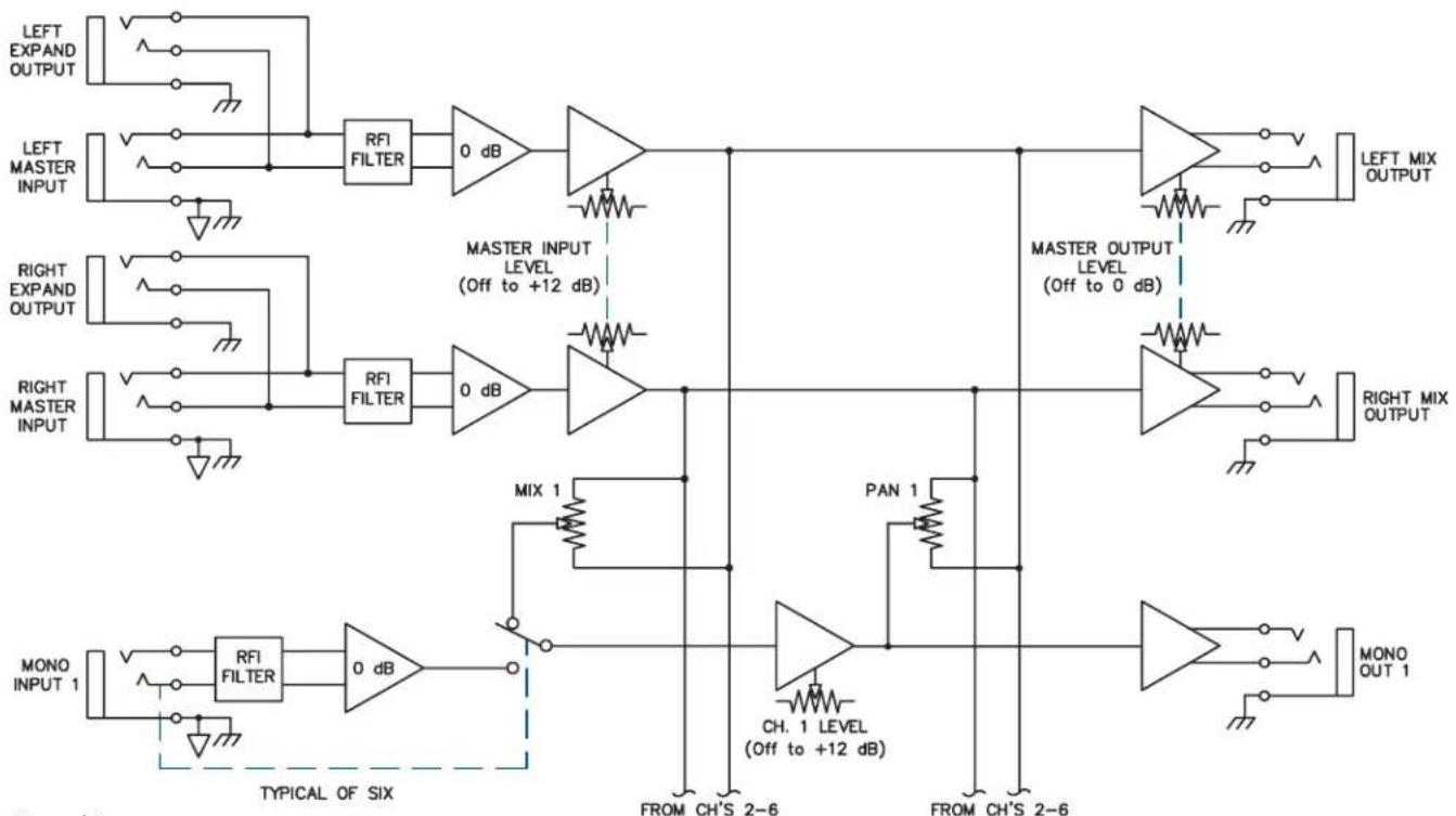
④ MASTER OUTPUT LEVEL controls the gain of the output stages and the amount of signal at the MIX OUTPUT jacks. It does not affect the level of any of the six MONO OUTPUTs. This allows an increase in headroom to eliminate overloading due to excessive combined signal from one or more Inputs. Range of gain is from Off to 0 dB (unity). Refer to the block diagram below.
⑤ POWER indicator: When this yellow LED is lit, the SM26S is ready to go (when it's off, it's not).
flowchart
graph TD
    A["LEFT EXPAND OUTPUT"] --> B["RFI FILTER"]
    C["LEFT MASTER INPUT"] --> B
    D["RIGHT EXPAND OUTPUT"] --> E["RFI FILTER"]
    F["RIGHT MASTER INPUT"] --> E
    G["MONO INPUT 1"] --> H["RFI FILTER"]
    I["TYPICAL OF SIX"] --> J["0 dB"]
    K["MIX 1"] --> L["MASTER INPUT LEVEL (Off to +12 dB)"]
    M["PAN 1"] --> N["MASTER OUTPUT LEVEL (Off to 0 dB)"]
    O["CH. 1 LEVEL (Off to +12 dB)"] --> P["FF"]
    Q["FROM CH'S 2-6"] --> R["FF"]
    S["FROM CH'S 2-6"] --> T["FF"]
    U["LEFT MIX OUTPUT"] --> V["FF"]
    W["RIGHT MIX OUTPUT"] --> X["FF"]
    Y["MONO OUT 1"] --> Z["FF"]
    style A fill:#f9f,stroke:#333
    style C fill:#f9f,stroke:#333
    style D fill:#f9f,stroke:#333
    style F fill:#f9f,stroke:#333
    style G fill:#f9f,stroke:#333
    style I fill:#f9f,stroke:#333
    style K fill:#f9f,stroke:#333
    style M fill:#f9f,stroke:#333
    style O fill:#f9f,stroke:#333
    style Q fill:#f9f,stroke:#333
    style O fill:#f9f,stroke:#333
    style U fill:#f9f,stroke:#333
Manual-2

① MASTER IN are balanced Tip-Ring-Sleeve (TRS) 14 " Master Inputs. These Inputs feed all six MONO OUTs when all MONO INs are not used. Connecting to individual MONO INs disconnects that channel from these Inputs (refer to the Block Diagram). For unbalanced operation use a standard mono 14 " plug; for balanced operation use a TRS (stereo) 14 " plug wired as follows:
TIP is signal + (connect to Pin 2 on a 3-pin connector).
RING is signal – (pin 3 in a 3-pin connector).
SLEEVE is chassis ground.
② MONO INPUTS are TRS 14 " jacks which accept either balanced or unbalanced mono signals. These are switching jacks which automatically bypass the MASTER IN jacks whenever a plug is inserted (see the Block Diagram). Same wiring conventions as ①.
③ MONO OUTPUTS are 1/4" TRS jacks that deliver either an unbalanced output (use TS plugs), or a balanced output (use TRS plugs). Follow wiring conventions as in ①.
④ EXPAND OUTS are 14 " TRS jacks connected in parallel with the MASTER IN jacks, allowing two or more SM26Ss to be daisychained for multiple splitting. Simply connect the EXPAND OUT to the MASTER IN of another SM26S; there is no limit to the number of expansions possible with the SM26S.
NOTE: These Expand Outputs are not buffered from the Master Inputs. Therefore it is not possible to mix both balanced and unbalanced lines in the same channel between several units: once the ring and sleeve are shorted anywhere in the chain (by using a mono plug) the entire line becomes unbalanced.
⑤ MIX OUTPUTS are balanced TRS 1/4" outputs controlled by the MASTER OUTPUT LEVEL control. They are fed either by the MASTER IN or by any of the six MONO INPUTS, or a combination of both (see The Swiss Army Mixer RaneNote). Follow wiring conventions as in ①.
⑥ Universal Voltage Input: via a miniature IEC 60320 C6 appliance inlet. This mates with an IEC 60320 C5 line cord (USA domestic). Do not lift the ground connection!
Operating Instructions
Since numerous applications exist for the SM26S, no single set of operational procedures control its use. The SM26S Swiss Army Mixer RaneNote (included) explores the many configurations of the SM26S in depth, and you should peruse it for applications information.
Internal Jumper Options
There exist within the SM26S some signal routing options, requiring removal of the top cover to move some jumpers. This must only be done with the power off by qualified service personnel.
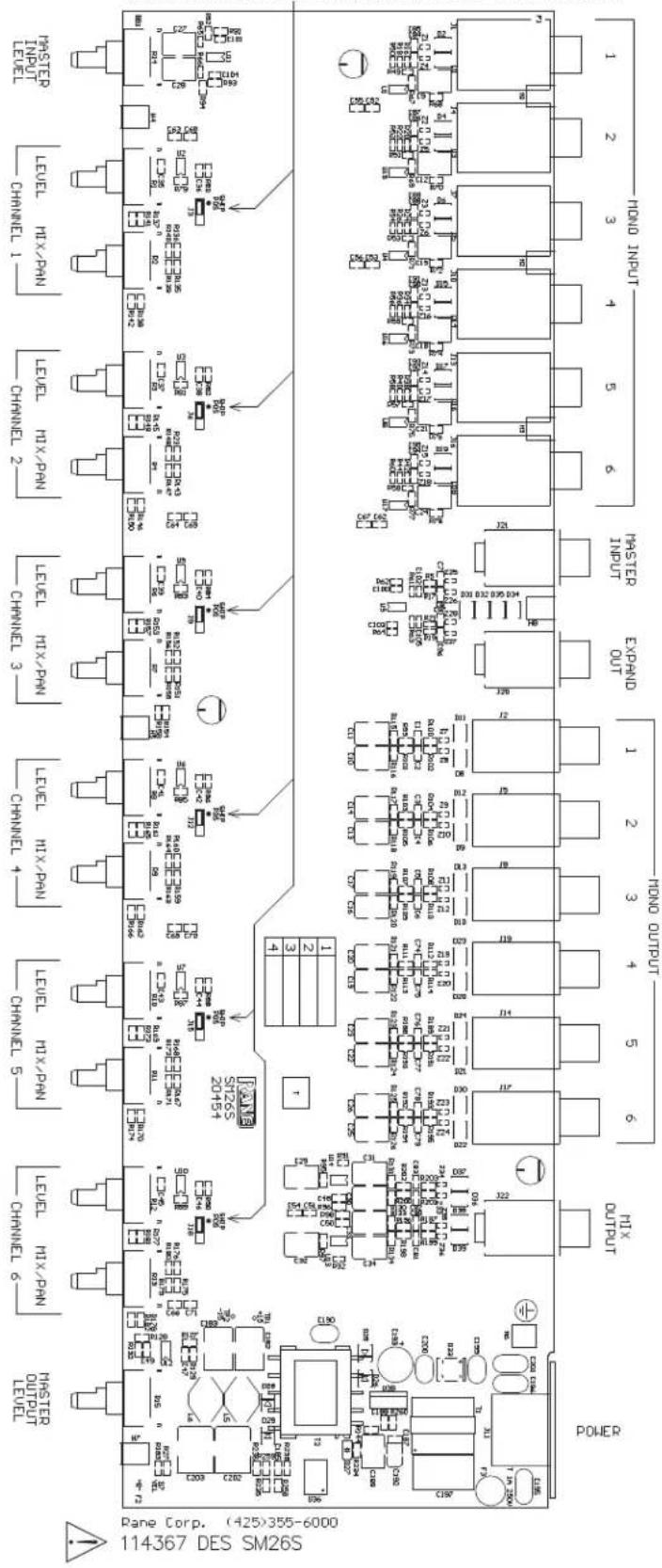
If an SM26S needs to have an additional set of independent outputs, as in a 2x4 stereo distribution amplifier (see Swiss Army Mixer, Figure 10), the LEFT and RIGHT MIX OUTPUTS can be used in addition to the 6 MONO OUTS. Normally, the LEFT and RIGHT MIX OUTPUTS produce the sum mix of all 6 LEVEL and PAN controls. To break any channel away from the Mix Output bus, internal jumpers have been provided. These are located behind the MIX/PAN controls for each channel. J3 connects MONO OUT 1 to the mix bus. J6 connects MONO OUT 2, J9 connects MONO OUT 3, and so on — see the board layout.
SHIP POSITION: SEND CHANNEL OUTPUT TO THE MIX BUS CHANGE JUMPER TO DISCONNECT AND ONLY ROUTE TO THE MONO OUT
Brand : Rane
Model : SM226S
Category : Séparateur de signal