
RSC-1650LSH - Laminator Royal Sovereign - Free user manual and instructions
Find the device manual for free RSC-1650LSH Royal Sovereign in PDF.


| Product Type | Roll Laminator |
| Model | RSC-1650LSH |
| Brand | Royal Sovereign |
| Laminating Width | 1650 mm (65 inches) |
| Max Laminating Speed | 5 m/min |
| Roller Diameter | 95 mm |
| Max Substrate Thickness | 25 mm (1 inch) |
| Max Temperature | 50°C (122°F) |
| Warm-Up Time | Approximately 10 minutes |
| Power Supply | 120V AC, 60Hz (US model) or 220-240V AC, 50/60Hz (international) |
| Power Consumption | 1600W (heater + motor) |
| Dimensions (W x D x H) | 1960 x 650 x 1120 mm (77.2 x 25.6 x 44.1 inches) |
| Weight | Not specified |
| Safety Features | Emergency stop switch, laser safety system, safety cover micro-switch |
| Control Panel | Keypad with temperature and speed adjustment, RUN/STOP/REV buttons |
| Pressure Adjustment | Manual via pressure lever and nip setting (7 positions) |
| Film Core Size | 2" and 3" auto grip |
| Foot Pedal | Included for hands-free operation |
| Cross Cutter | Integrated at rear exit table |
| Take-Up Device | Chain link to main motor |
| Maintenance Cleaning | Wipe body with damp cloth; remove adhesive with rubber eraser on rollers; lubricate drive chain every 6 months or 1000 hours |
| Included Accessories | 6 auto grips (3" & 2"), L-wrenches, dust cover, spare fuses, owner's manual |
| Warranty | 1 year parts and labor (6 months on rollers) |
Frequently Asked Questions - RSC-1650LSH Royal Sovereign
User questions about RSC-1650LSH Royal Sovereign
0 question about this device. Answer the ones you know or ask your own.
Ask a new question about this device
Download the instructions for your Laminator in PDF format for free! Find your manual RSC-1650LSH - Royal Sovereign and take your electronic device back in hand. On this page are published all the documents necessary for the use of your device. RSC-1650LSH by Royal Sovereign.
USER MANUAL RSC-1650LSH Royal Sovereign
OWNER'S MANUAL
RSC-LS/LSH SERIES Laminators
natural_image
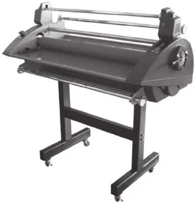
Black industrial printing press machine with roller and stand (no visible text or symbols)Read all instructions carefully before use.
For any Customer Support needs please choose the
Customer Support tab on www.royalsovereign.com
Royal Sovereign International Inc.
www.royalsovereign.com
TABLE OF CONTENTS
TOPIC PAGE
- Introduction 2
- Safety Precautions.... 2
- Installation.... 3
- Included with Laminator.... 4
- Product Identification ....5
- Control Panel 6
- Roller Nip Settings 7
- Using Foot Pedal and Remote Control....7
- Using Cross Cutter 8
- Loading Film 9
- Threading Film
11.1.Decaling....10
11.2. Mounting 12 - Installation of the Front Feed and Rear Rewind Options.... 13
- Maintenance 14
- Troubleshooting.... 14
- Specifications.... 15
- Warranty.... 16
1. INTRODUCTION
Thank you for choosing a Royal Sovereign laminator. It has been designed and manufactured to provide years of continuous service. For complete operating and maintenance information please read this manual thoroughly. Upon receipt of your laminator, please inspect the box, the machine and all other contents for shipping damage. Damage should be brought to the immediate attention of the delivering carrier (See page 4 for list of shipment elements).
2. SAFETY PRECAUTIONS
Failure to comply with any of the following safety procedures could result in serious injury. Please read the instructions carefully and keep for future reference.
- Only a licensed electrician should install wiring and outlet for the laminator.
- Ensure the unit is plugged into a properly grounded outlet with the correct voltage.
- Keep hands and clothing (i.e. Neckties) away from rollers. The rollers have pinch points that can trap body parts or clothing and cause serious injury.
- Keep flammable and wet objects away from the machine.
- Place machine on a level surface.
- Avoid excessive sunlight, humidity and extreme temperatures.
- Ensure the unit is turned off, cooled, and unplugged from the outlet prior to moving and/or repairing.
- Keep out of reach of children.
- Only Royal Sovereign authorized maintenance and service technicians should make repairs.
- Do not attempt to laminate items that exceed total recommended material thickness for the unit
- When cleaning the machine, don't use flammable sprays or materials.
- Do not touch the rollers when they are hot or place foreign objects inside the machine.
- Do not cover the surface of the machine until the machine has completely cooled.
3. INSTALLATION
Note: The laminator should be installed by a trained service technician.
The laminator comes fully assembled, except for the feed table and paper guide to avoid shipping damage. Upon arrival, thoroughly inspect the unit. It is imperative that any shipping damage is reported and a claim is filed with the delivering carrier immediately upon receipt.
The laminator should be located in an area with adequate work space for feeding graphics and lamination materials.
Avoid placing the laminator in a dusty area or near sources of extreme heat or cold.
Once the laminator is in place, lock the casters into position("ON" position). Always unlock the casters ("OFF" position) when moving to a different location.
ELECTRICAL REQUIREMENTS
Royal Sovereign recommends that a licensed electrician ensures proper power installation to your laminator in accordance with electrical codes in your area.
The laminator should have a dedicated power line.
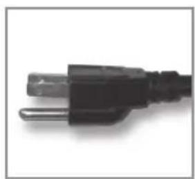
natural_image
Close-up of a black electrical outlet plug (no text or symbols visible)120V UL
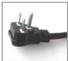
natural_image
Close-up of a black electrical outlet plug with two metallic pins (no text or symbols visible)230V UL
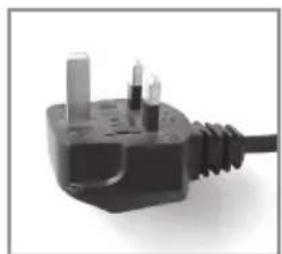
natural_image
Close-up of a black electrical outlet plug with three metallic pins and a coiled cable (no text or symbols visible)240V UK
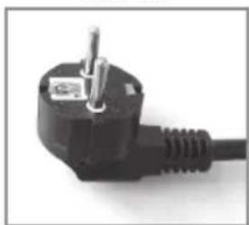
natural_image
Close-up of a black electrical outlet plug with a metal screw and terminal socket (no text or symbols visible)220V EU
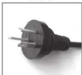
natural_image
Close-up of a black electrical outlet plug with three leads (no text or symbols visible)220V AU
4. INCLUDED WITH LAMINATOR
Thoroughly inspect the parts and the unit. It is imperative that any missing parts are reported and a claim is filed with the reseller immediately upon receipt of shipment.
| Part Name | Quantity Picture | |
| Laminator | 1 | 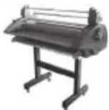 |
| Owner's Manual | 1 |  |
| 3'' (76mm) / 2" (57mm) Auto Grip | 6/6 |  |
| L-wrench (2.5/6) | 11/1 |  |
| Dust Cover | 1 | 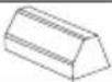 |
| Spare Motor Fuse - FUSE(50T)(6.3A) | 1 | 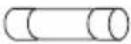 |
| Spare Main Power Fuse - FUSE(65TS)(5A) | 1 | 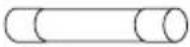 |
- PRODUCT IDENTIFICATION
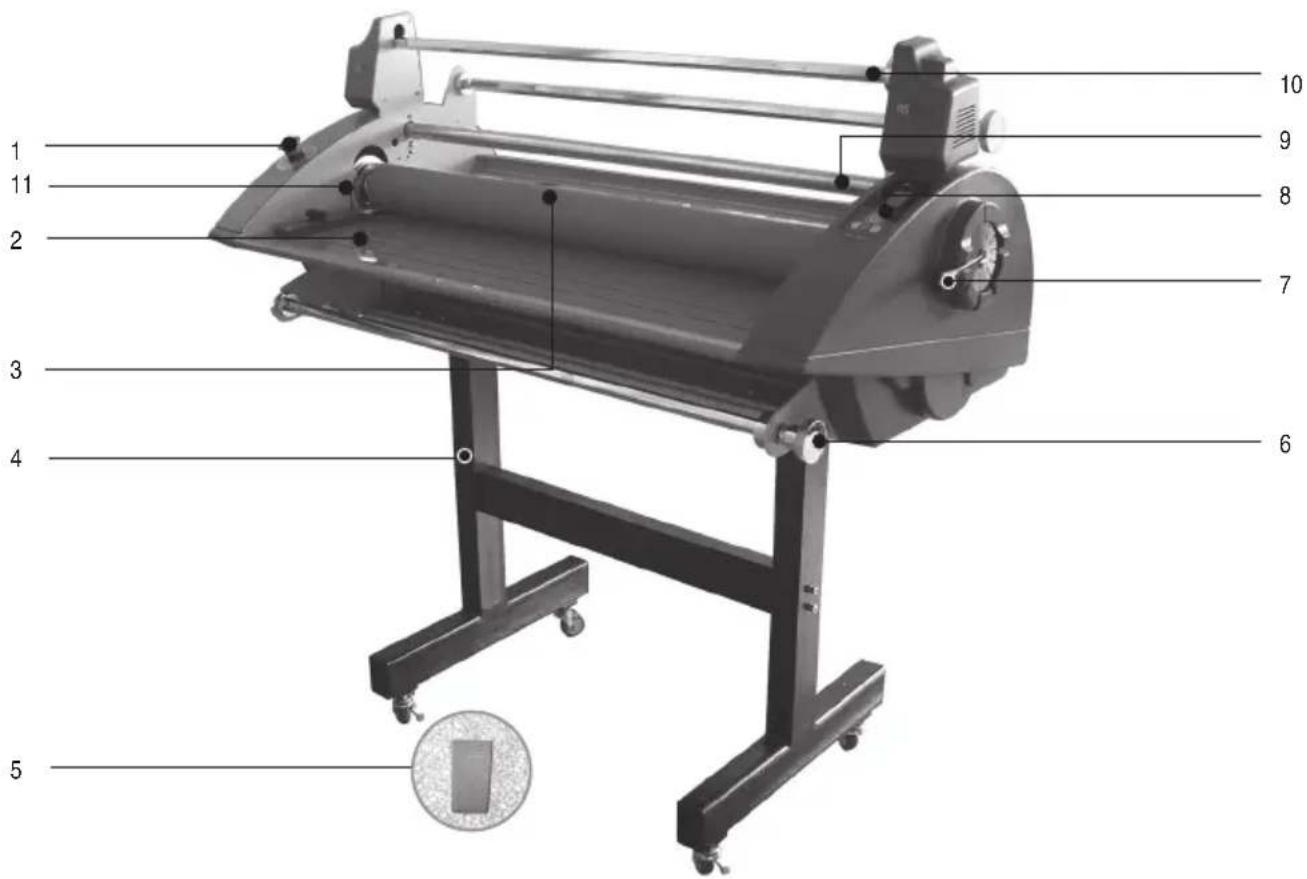
| NO PART | NAME RSC-LS/RSC-LSH | |
| 1 EMERGENCY SWITCH O | ||
| 2 FEED TABLE O | ||
| 3 MAIN ROLLER O | ||
| 4 ASSEMBLY STAND O | ||
| 5 FOOT PEDAL O | ||
| 6 TENSION CONTROL KNOBS O | ||
| 7 PRESSURE LEVER O | ||
| 8 CONTROL PANEL O | ||
| 9 UPPER IDLE BAR O | ||
| 10 | RELEASE LINER TAKE UP | O |
| 11 | LASER SYSTEM FOR SAFETY | O |
6. CONTROL PANEL
When the machine is initially turned on, the LED display window will show the speed and temperature set at 1.
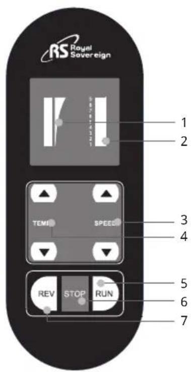
RSC-LSH SERIES RSC-LS SERIES
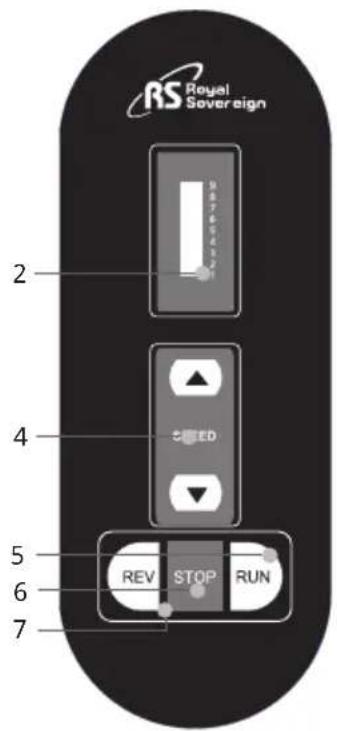
Control Buttons
- TEMPERATURE DISPLAY: Display's current temperature.
- SPEED DISPLAY: Display's current Speed.
- TEMPERATURE BUTTON : To change the temperature (max. 122°F, 50°C) of the upper roller, press up or down arrow button.
- SPEED BUTTON: Adjusting the speed of the rollers. To change the speed of the rollers, press the up or down arrow button.
- RUN: To start the rollers.
- STOP: To stop the rollers.
- REV: To reverse the rollers, press and hold the REVERSE button.
7. ROLLER NIP SETTING
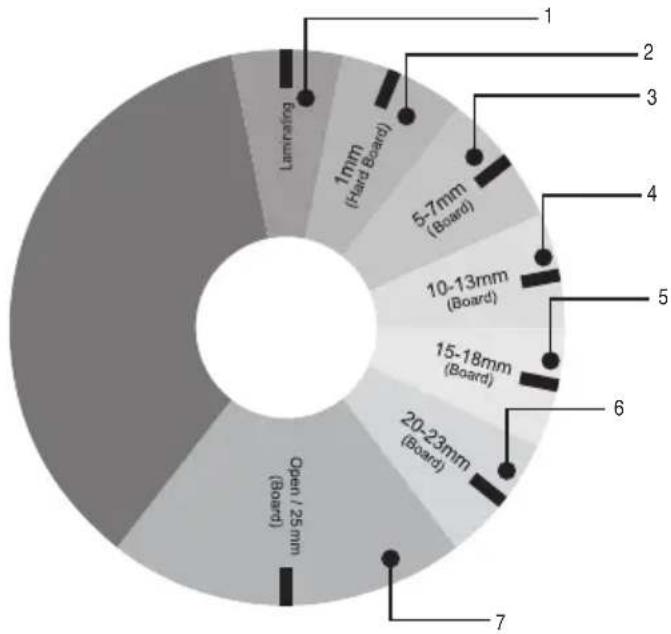
It is important to adjust the roller nip settings to the appropriate thickness of the board being used. Use the guide below to adjust to the correct position.
| NO. Inches | Metric (mm) | |
| 1 Lamination Lamination | ||
| 2 1/25 | ” | 1 |
| 3 3/6 | “~1/4” | 5~7 |
| 4 3/8 | “~1/2” | 10~13 |
| 5 3/5 | “~18/25” | 15~18 |
| 6 4/5 | “~3/25” | 20~23 |
| 7 | 1” | 25 |
NOTE: If you don't want to laminate, please place the pressure leverto the "Open position(NO.7)".
pie
| Category | Value | |---|---| | Open 1/25 mm (Board) | 100 | | 1mm (Hard Board) | 30 | | 5-7mm (Board) | 25 | | 10-13mm (Board) | 20 | | 15-18mm (Board) | 15 | | 20-23mm (Board) | 10 | | 2-4mm (Board) | 10 | | 6-8mm (Board) | 5 | | 1mm (Board) | 5 |8. USING FOOT PEDAL AND REMOTE CONTROL
USING FOOT PEDAL
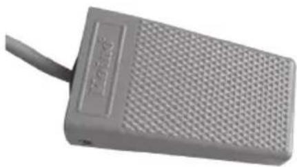
Place the foot pedal on the floor in front of the machine. Press it all along, the roller will run slowly in despite of the RUN button is on or off. So that you can lay the lamination well.
natural_image
Exterior view of a gray rectangular electronic device with a mesh grille and a cable (no visible text or symbols)9. USING CROSS CUTTER
The cross cutter is located on the rear exit table of the machine.
-
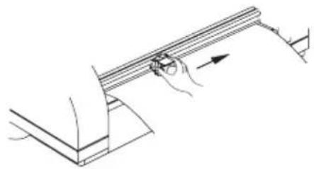
After lamination, move the cutter approximately to the center of the completed application at the desired point of detachment (Figure 1).
-
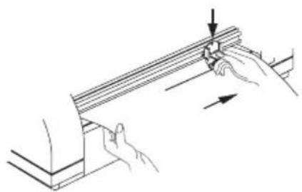
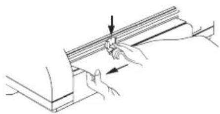
Grasp film with one hand, press the cutter downward into the application and slide it first to one end of the application, then to the other end to complete the cut (Figure 2 & 3).
natural_image
Line drawing of a hand holding a metal rod with an arrow indicating direction (no text or symbols)Figure 1
natural_image
Illustration of hands holding a thin metal beam with a bolt, showing force direction (no text or symbols)Figure 2
natural_image
Illustration of hands installing or adjusting a structural component with an arrow indicating direction (no text or symbols present)Figure 3
10. LOADING FILM
Royal Sovereign films are wound with the adhesive side facing the inside of the roll (adhesive in).
Loading films to upper and lower film shafts: (See page 5 for assistance with parts identification.)
-
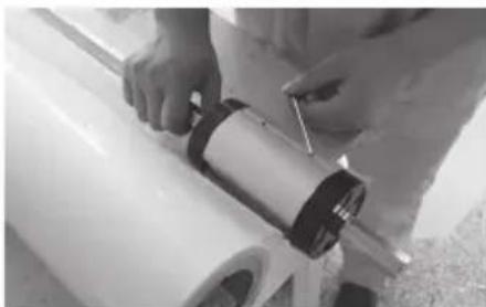
Adjust the auto grip to fit to the film and tighten the auto grip screw (Figure 1).
-
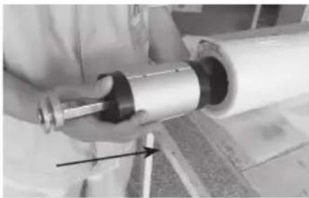
Remove the upper and lower film shafts from the machine and load the films (Center the upper and lower films on the shaft). Note the direction of the adhesives on the lower and upper films (Figure 2).
-
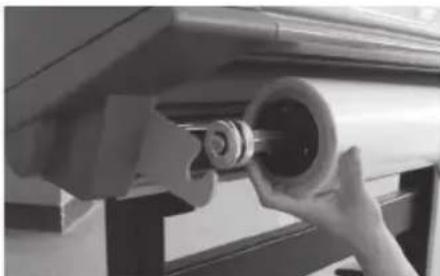
Load the upper and lower film shafts on the machine (Figure 3).
natural_image
Person installing or adjusting a cylindrical component on a white surface (no visible text or symbols)Figure 1
natural_image
Close-up of a hand holding a metallic cylindrical object with a black arrow pointing to it, no visible text or symbols.Figure 2
natural_image
Close-up of hands holding a cylindrical mechanical component, possibly a valve or pump, with no visible text or symbols.Figure 3
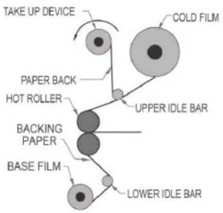
11. THREADING FILM
flowchart
graph TD
    A["BASE FILM"] --> B["BACKING PAPER"]
    B --> C["HOT ROLLER"]
    C --> D["PAPER BACK"]
    D --> E["TAKE UP DEVICE"]
    E --> F["COLD FILM"]
    F --> G["UPPER IDLE BAR"]
    G --> H["LOWER IDLE BAR"]
11.1. Decaling
- Turn the power switch on ("I" position). The Power switch is located on the rear left side of the unit.
- Complete the steps as in the "LOADING FILM" section (see page 10).
- Set the top roller to the desired temperature (RSC-1400H)
- Take off the Frame-Paper Guide and the Feed Table.
- Pull the top film down over the Safety Cover to the bottom of the craft paper/mounting film.
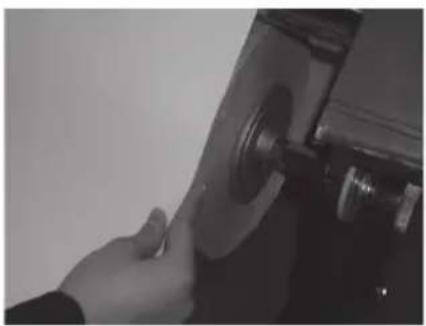
- Align and center the craft paper/mounting film to the top film and tighten the two lower core screws (Figure 1).
- Thread the top film underneath the Upper Idle Bar.(Figure 2)
- Tape the top film on to the Release Liner Take-Up.(Figure 2)
natural_image
Close-up of a hand operating a mechanical device with a circular component (no visible text or symbols)Figure 1
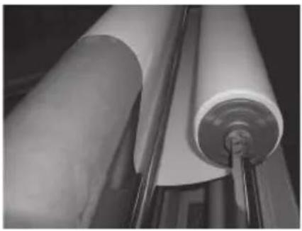
natural_image
Close-up of rolled paper sheets with a metal rod inserted, no visible text or symbolsFigure 2
-
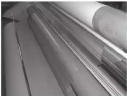
Cut and separate the release liner and the film. (Figure 3)
-
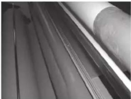
Thread the craft paper behind the Lower Idle Bar to the top film that is resting on the main roller (do not use the Lower Idle Bar for Mounting). (Figure 4)
- Reinstall the Feed Table and the Frame-Paper Guide, and close the Safety Cover.
- Adjust the nip setting to appropriate gap.
- Insert and push the leader board until they reach the front nip point.
- Push the Run button.
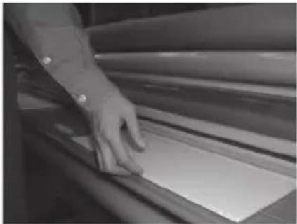
- Push the leader board into the rollers. (Figure 5)
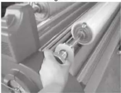
- Adjust the top and bottom tension knob by rotating it clockwise or counterclockwise. Turn it until the top and bottom roll films have some resistance (The tension varies depending on the film thickness; the thicker the film the more tension is required). (Figure 6)
natural_image
Stacked paper sheets with metallic sheets, no visible text or symbolsFigure 3
natural_image
Close-up of a metallic cylindrical object with parallel grooves, possibly a tool or component (no visible text or symbols)Figure 4
natural_image
Close-up of a hand pressing down on a rolled-up sheet of paper (no visible text or symbols)Figure 5
natural_image
Close-up of a hand operating a lathe machine with rollers (no visible text or symbols)Figure 6
- Press the Stop button when the leader board has completely exited from the rollers.
- Use the Cross Cutter to cut the leader board from the web (see page 9).
- Set the nip setting to the appropriate position for the Over-lamination / Decaling application.
11.2 Mounting
-
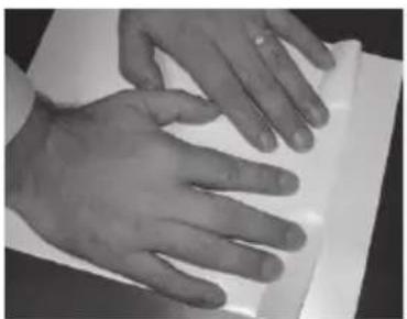
Lay the decaled image face down on a flat surface. Carefully peel back and put a crease along the edge of the release liner (Approximately 1 inch or 25mm, Figure 1).
-
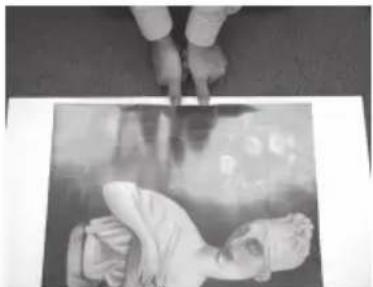
With the image facing up, align the image onto the board. Press firmly from the center out (Figure 2).
-
Adjust the pressure lever to ensure the proper opening (Figure 3).
-
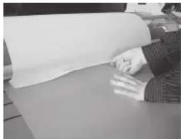
Flip the image over the upper roller and hold on to the release liner (Figure 4).
-
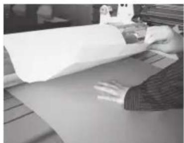
Press the foot pedal once, and then let it go while slowly pulling the release liner as the board enters the main roller nip (Figure 5).
Press the foot pedal once again when the board has completely exited from the rear of the unit. Trim the board if necessary.
natural_image
Close-up of two hands typing on a white surface, no text or symbols visibleFigure 1
natural_image
Black-and-white photo of a person lying down with hands pointing at the image (no visible text or symbols)Figure 2
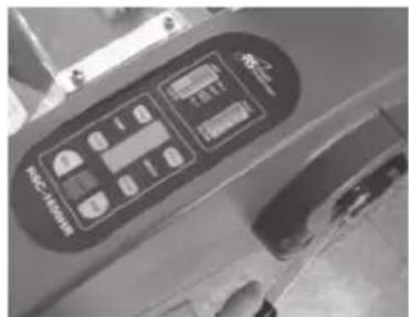
Figure 3
natural_image
Person handling a large sheet of paper or paper on a flat surface (no visible text or symbols)Figure 4
natural_image
Person handling a large sheet of paper or document on a table (no visible text or symbols)Figure 5
12. INSTALLATION OF FRONT FEEDER AND REAR REWINDER OPTIONS
NOTE: Below options are to be installed by an authorized RS reseller.
Installation of the Front Feeder Option (Includes 2 brackets, one spindle, and mounting hardware).
-
Remove the rear cover by removing all 12 screws (4 top, 4 bottom, and 2 on each side) (Figure 5 & 6).
-
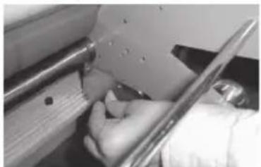
Install the Front Feeder to the inside of the front frames using four 1/4" (M6) hexagon bolts on each side (Figure 1).
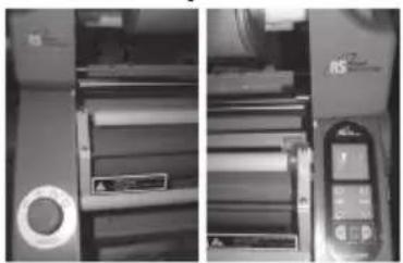
Installing the Rear Rewinder Option (Includes motorized winder, bracket, one spindle, and mounting hardware). - Remove the left and right covers by using a screwdriver (four screws on each side cover) (Figure 2 & 3).
-
Remove the lever knob screw and lever (Figure 4).
-
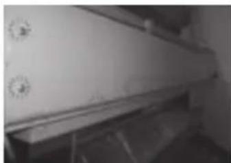
Remove the rear cover by removing all 12 screws (4 top, 4 bottom, and 2 on each side) (Figure 5 & 6).
natural_image
Close-up of a hand using a tool to cut or inspect a metal component (no visible text or symbols)Figure 1
natural_image
Two-panel black-and-white photo showing a machine with rollers and a mobile phone, no visible text or symbols.Figure 2 Figure 3
natural_image
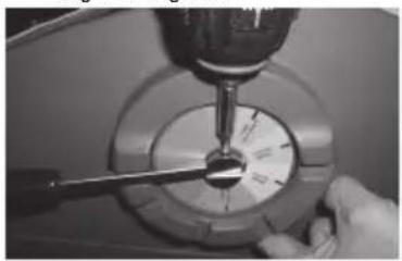
Close-up of a hand using a tool to measure a circular dial or gauge (no visible text or symbols)Figure 4
natural_image
Exterior view of a modern office building (no signage)Figure 5 Figure 6
natural_image
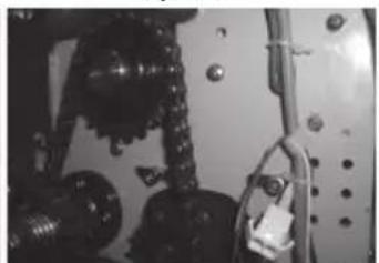
Close-up of mechanical components including gears and springs (no visible text or symbols)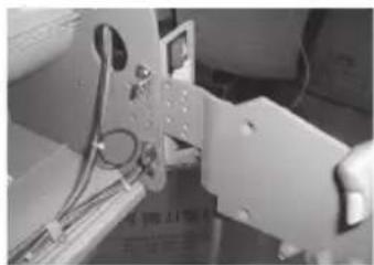
natural_image
Close-up of a mechanical assembly with wires and components (no visible text or symbols)Figure 7
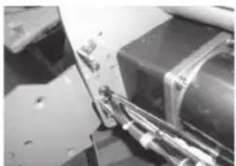
- Disassemble the power switch bracket and place the left rewinder outside of the frame; fasten with round head 3/16"(M5) screws (included in the option kit). Then, reinstall the power switch bracket (Figure 7).
- Install the right rewinder on the outside of the frame and connect the motor wire connector to the rear wire (Figure 8 & 9).
- Reinstall the rear cover.
- Reinstall the side covers.
- Reinstall the lever knob and screw.
natural_image
Close-up of mechanical components with visible wiring and mounting brackets (no text or symbols)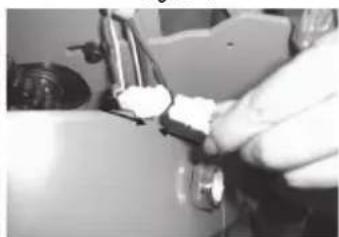
natural_image
Close-up of a hand using a tool to adjust or install a mechanical component (no visible text or symbols)Figure 9 Figure 8
13. MAINTENANCE
Cleaning the Body of the laminator
- To clean the machine body, dampen a cloth with water only and gently wipe the machine clean.
Removing Adhesive Build Up
- Remove the film from the laminator.
- Use a damp (water only) cloth and a rubber gum eraser to remove the adhesive on the Teflon (metal) and silicone rollers.
Note: Rub firmly but do not scrub the rollers vigorously as this may scratch the surface. Do not use sharp metal objects, steel wool, or abrasives, as these may also damage the rollers.
Lubrication
- Drive chain and sprockets should be lubricated with either a light coat of gear lube or heavy grease (lithium grease) after 6 months or 1000 hours of operation, whichever comes first.
14. TROUBLESHOOTING
| Symptom Cause Possible Solution | ||
| Machine will not turn on: | a. Power plug is not plugged in.b. Power switch is in “0” (Off) position.c. Tripped circuit breaker.d. Blown main power fuse. | a. Plug the power cord into appropriate outlet.b. Put the power switch to the “I” (On) position.c. Reset the circuit breaker.d. Replace the fuse. |
| There is power, but the rollers are not turning after the “RUN” button is pressed: | a. Emergency switch(es) is (are) engaged.b. Paper guide is not installed correctly.c. Blown motor fuse. | a. Disengage the emergency switch(es).b. Properly install the paper guide so that the micro switch is activated.d. Replace the motor fuse. |
| The unit is not heating up: | a. Did not raise the temperature. a. Raise the temperature. | |
| Curled lamination: | a. Upward curl.b. Downward curl. | a. Loosen the top roll film tension.b. Loosen the bottom roll film tension. |
- SPECIFICATIONS
| DESCRIPTION | RSC-880LS/LSH | RSC-1120LS/LSH | RSC-1400LS/LSH | RSC-1650LS/LSH | ||||
| Power supply AC100,200 220~240 50/60Hz AC 120V 60Hz | ||||||||
| Power Consumption 100W 900W 100W 1100W 100W 1500W 100W 1600W | ||||||||
| Roller Diameter ø82 ø82 ø82 ø95 | ||||||||
| Safety System Laser System for Safety Laser System for Safety Laser System for Safety | ||||||||
| Laminating Speed (max) 5m/min 5m/min 5m/min 5m/min | ||||||||
| Laminating Width 880mm 1120mm 1400mm 1650mm | ||||||||
| Laminating Films 50mic-500mic 50mic-500mic 50mic-500mic | ||||||||
| Foam Board | 1mm-25mm | 1mm-25mm | 1mm-25mm | 1mm-25mm | ||||
| Thickness of substrated (Paper) | 80g/m2~350g/m2 | 80g/m2~350g/m2 | 80g/m2~350g/m2 | 80g/m2~350g/m2 | ||||
| Speed Control | Key Pad | Key Pad | Key Pad | Key Pad | ||||
| Pressure Adjustment | Manual | Manual | Manual | Manual | ||||
| Max. temperature | — | 50°C(122°F) | — | 50°C(122°F) | — | 50°C(122°F) | — | 50°C(122°F) |
| Ready time | — | 10min | — | 10min | — | 10min | — | 10min |
| Take up device | chain link to main motor | chain link to main motor | chain link to main motor | chain link to main motor | ||||
| Film Core | 2"&3" Autor Grip | 2"&3" Autor Grip | 2"&3" Autor Grip | 2"&3" Autor Grip | ||||
| Take of Main Motor | DC Motor | DC Motor | DC Motor | DC Motor | ||||
| Cross Cutter | Yes Yes Yes Yes | |||||||
| Remote Control Switch | No | No | No | No | ||||
| Foot S / W | Yes Yes Yes Yes | |||||||
| Dimensions (W*L*H) | 1190*650*1120 | 1430*650*1120 | 1710*650*1120 | 1960*650*1120 | ||||
16. WARRANTY
Royal Sovereign International warrants the equipment sold is free from defects in material and workmanship for a period of One (1) year for Parts and Labor from the date of installation, excluding lamination rollers which are warranted for Six (6) months. This warranty is extended only to the original purchaser. This warranty is the only warranty made by Royal Sovereign International and cannot be modified or amended. Royal Sovereign's sole and exclusive liability and the customer's sole and exclusive remedy under this warranty shall be, at Royal Sovereign's option, to repair or replace any such defective part or product. These remedies are only available if Royal Sovereign's examination of the product discloses to Royal Sovereign's satisfaction that such defects actually exist and were not caused by misuse, neglect, attempt to repair, unauthorized alternation or modification, incorrect line voltage, fire, accident, flood or other hazard.
All warranty claims must be filed through the authorized Royal Sovereign dealer or reseller through which the equipment was originally purchased. Model, serial number and date of delivery are required for all claims.
The warranty made herein is in lieu of all other warranties, expressed or implied, including any warranty or merchantability or fitness for a particular purpose. Royal Sovereign will not be liable for personal damage or personal injury (unless primarily caused by its negligence), loss of profit, or other incidental or consequential damages arising out of the use or inability to use this equipment.
LIMITED WARRANTY
This warranty specifically does not cover damage to laminating rollers caused by knives, razor blades, or any sharp objects or abrasives, or failure caused by adhesives, or damage caused by lifting, tilting or improper use of the machine. Warranty repair or replacement by Royal Sovereign or its authorized Reseller(s) does not extend the warranty beyond the initial one year period from the date of installation. Unauthorized customer alterations will void this warranty.
CORPORATE HEADQUARTERS
Royal Sovereign International Inc.
2 Volvo Drive, Rockleigh, NJ 07647 U.S.A.
TEL : +1) 800-397-1025 FAX : +1) 201-750-1022
E-mail: info@royalsovereign.com
RS Holland B.V.
Planetenweg 75 2132HM Hoofddorp, The Netherlands.
E-mail: purchaseorder@royalsovereign.com
RS Canada Inc.
164 Oakdale Road, Toronto, Ontario M3N 2S5 CANADA
TEL: +1) 416-741-8400 FAX: +1) 416-741-8185
E-mail: info@royalsovereign.com
Royal Sovereign Inc.
1001, World Meridian II, 426-5, Gasan-dong,
Geumcheon-gu, Seoul, 153-759, KOREA
TEL : +82)2-2025-8800 FAX : +82)2-2025-8830
E-mail : sales@royalsovereign.com
RS International Australia PTY. LTD.
30 Prime Drive, Seven Hills, NSW 2147, Australia
TEL : +61) 2-9674-2127
E-mail : salesaust@royalsovereign.com
- OWNER'S MANUAL
- RSC-LS/LSH SERIES Laminators
- Royal Sovereign International Inc.
- TABLE OF CONTENTS
- TOPIC PAGE
- INTRODUCTION
- SAFETY PRECAUTIONS
- INSTALLATION
- Note: The laminator should be installed by a trained service technician.
- ELECTRICAL REQUIREMENTS
- INCLUDED WITH LAMINATOR
- CONTROL PANEL
- Control Buttons
- ROLLER NIP SETTING
- USING FOOT PEDAL AND REMOTE CONTROL
- USING FOOT PEDAL
- USING CROSS CUTTER
- LOADING FILM
- THREADING FILM
- Decaling
- Mounting
- INSTALLATION OF FRONT FEEDER AND REAR REWINDER OPTIONS
- MAINTENANCE
- Cleaning the Body of the laminator
- Removing Adhesive Build Up
- Lubrication
- TROUBLESHOOTING
- WARRANTY
- LIMITED WARRANTY
- RS Holland B.V.
- RS Canada Inc.
- Royal Sovereign Inc.
- RS International Australia PTY. LTD.
Brand : Royal Sovereign
Model : RSC-1650LSH
Category : Laminator