
Chainhoist Controller CHC-4 - Lighting Botex - Free user manual and instructions
Find the device manual for free Chainhoist Controller CHC-4 Botex in PDF.


| Product Type | Motor controller for electric chain hoists |
| Brand | Botex |
| Model | Chainhoist Controller CHC-4 (also available as CHC-8) |
| Number of Controlled Motors | 4 (CHC-4) or 8 (CHC-8) |
| Input Connection | Cable with CEE plug, 400 V ~ 50 Hz, 32 A per phase |
| Output Connections (CHC-4) | 4 × 4-pin CEE chassis sockets with hinged lid, 1 × 16-pin multi-pin industrial connector |
| Output Connections (CHC-8) | 4 × 4-pin CEE chassis sockets with hinged lid, 2 × 16-pin multi-pin industrial connectors |
| Max Load per Motor | 1.9 kW |
| Max Total Load | 9 kW |
| Circuit Breakers | 3 × 13 A (type D) for phases; 6 A (type C) for control circuit |
| Emergency Stop | Yes, with locking function |
| Control | Rotary switches for direction (UP/OFF/DOWN) and momentary RUN button |
| Indicators | Phase indicator lights (L1, L2, L3) and RUN indicator |
| Degree of Protection | IP20 |
| Installation | 19-inch rack mount, 4 RU |
| Dimensions (W x H x D) | 483 mm x 278 mm x 178 mm |
| Weight | 8.75 kg (CHC-4), 10.3 kg (CHC-8) |
| Operating Temperature | 0 °C to 40 °C |
| Relative Humidity | ≤ 50%, non-condensing |
| Intended Use | Professional control of electric chain hoists |
| Safety Features | Emergency stop, circuit breakers, phase monitoring |
| Compliance | WEEE compliant |
Frequently Asked Questions - Chainhoist Controller CHC-4 Botex
User questions about Chainhoist Controller CHC-4 Botex
0 question about this device. Answer the ones you know or ask your own.
Ask a new question about this device
Download the instructions for your Lighting in PDF format for free! Find your manual Chainhoist Controller CHC-4 - Botex and take your electronic device back in hand. On this page are published all the documents necessary for the use of your device. Chainhoist Controller CHC-4 by Botex.
USER MANUAL Chainhoist Controller CHC-4 Botex
Chainhoist Controller CHC-4, CHC-8
motor controller
Musikhaus Thomann
Thomann GmbH
1.1 Further information.... 7
1.2 Notational conventions.... 8
1.3 Symbols and signal words.... 9
2 Safety instructions.... 11
3 Features.... 16
4 Installation.... 17
4.1 Mechanical installation.... 17
4.2 Electrical installation.... 18
5 Starting up.... 20
6 Connections and controls.... 23
7 Operating.... 31
8 Technical specifications.... 34
9 Troubleshooting.... 38
Table of contents
10 Protecting the environment.... 41
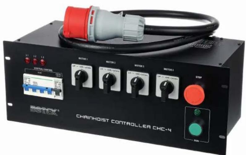
Chainhoist Controller CHC-4, CHC-8 motor controller
1 General information
This user manual contains important information on the safe operation of the device. Read and follow all safety notes and all instructions. Save this manual for future reference. Make sure that it is available to all persons using this device. If you sell the device to another user, be sure that they also receive this manual.
Our products and user manuals are subject to a process of continuous development. We therefore reserve the right to make changes without notice. Please refer to the latest version of the user manual which is ready for download under www.thomann.de.
1.1 Further information
On our website (www.thomann.de) you will find lots of further information and details on the following points:
| Download This manual is also available as PDF file for you to download. | |
| Keyword search | Use the search function in the electronic version to find the topics of interest for you quickly. |
| Online guides | Our online guides provide detailed information on technical basics and terms. |
| Personal consultation For personal consultation please contact our technical hotline. | |
| Service | If you have any problems with the device the customer service will gladly assist you. |
1.2 Notational conventions
This manual uses the following notational conventions:
Letterings
The letterings for connectors and controls are marked by square brackets and italics.
Examples: [VOLUME] control, [Mono] button.
Displays
Texts and values displayed on the device are marked by quotation marks and italics.
Examples: '24ch', 'OFF'.
Instructions
The individual steps of an instruction are numbered consecutively. The result of a step is indented and highlighted by an arrow.
Example:
- Switch on the device.
- Press [Auto].
⇒ Automatic operation is started.
- Switch off the device.
1.3 Symbols and signal words
In this section you will find an overview of the meaning of symbols and signal words that are used in this manual.
| Signal word Meaning | |
| DANGER! This combination of symbol and signal word indicates an immediate dangerous situation that will result in death or serious injury if it is not avoided. | |
| CAUTION! This combination of symbol and signal word indicates a possible dangerous situation that can result in minor injury if it is not avoided. | |
| NOTICE! This combination of symbol and signal word indicates a possible dangerous situation that can result in material and environmental damage if it is not avoided. | |
| Warning signs Type of danger | |
 | Warning – high-voltage. |
 | Warning – danger zone. |
2 Safety instructions
Intended use
This device is used to control electrically operated chain hoists. The device is designed for professional use and is not suitable for use in households. Use the device only as described in this user manual. Any other use or use under other operating conditions is considered to be improper and may result in personal injury or property damage. No liability will be assumed for damages resulting from improper use.
This device may be used only by persons with sufficient physical, sensorial, and intellectual abilities and having corresponding knowledge and experience. Other persons may use this device only if they are supervised or instructed by a person who is responsible for their safety.
Safety

DANGER!
Danger for children
Ensure that plastic bags, packaging, etc. are disposed of properly and are not within reach of babies and young children. Choking hazard!
Ensure that children do not detach any small parts (e.g. knobs or the like) from the unit. They could swallow the pieces and choke!
Never let children unattended use electrical devices.
DANGER!
Electric shock caused by high voltages inside
Within the device there are areas where high voltages may be present. Never remove any covers.
There are no user-serviceable parts inside.
Do not use the device if covers, protectors or optical components are missing or damaged.
DANGER!
Electric shock caused by short circuit
Always use a properly insulated CEE cable to connect the unit to the 400 V mains grid. Do not modify the CEE cable or the CEE plug. Failure to comply may result in electric shock and risk of fire and loss of life. If in doubt, seek advice from a registered electrician.
DANGER!
Hazardous voltage
Hazardous voltage may be present at cable ends and screw terminals.
The connection of screw terminals as well as all maintenance and repair work on the electrical installation of the device must only be performed by qualified electrical personnel in volt-free condition. Failure to do so may result in electric shock and risk of fire and loss of life.
By all means you have to observe all electrical safety instructions applicable at the place of operation.

NOTICE!
Risk of fire
Do not block areas of ventilation. Do not install the device near any direct heat source. Keep the device away from naked flames.

NOTICE!
Operating conditions
This device has been designed for indoor use only. To prevent damage, never expose the device to any liquid or moisture. Avoid direct sunlight, heavy dirt, and strong vibrations.

NOTICE!
Power supply
Before connecting the device, ensure that the input voltage (AC outlet) matches the voltage rating of the device and that the AC outlet is protected by a residual current circuit breaker. Failure to do so could result in damage to the device and possibly injure the user.
Unplug the device before electrical storms occur and when it is unused for long periods of time to reduce the risk of electric shock or fire.
3 Features
■ Motor control for directly controlled electric chain hoists
■ Independent control for up to
- 4 motors (item no. 422822)
- 8 motors (item no. 422852)
- Input
- Cable with CEE plug
■ Outputs
- Item no. 422822: 4 × 4 -pin CEE chassis sockets with hinged lid, 1 × 16 -pin multi-pin industrial connector for use with a breakout box
- Item no. 422852: 4 × 4 -pin CEE chassis sockets with hinged lid, 2 × 16 -pin multi-pin industrial connector for use with a breakout box
■ Line circuit breaker for each phase
Line circuit breaker for rotary switch and emergency stop switch
4 Installation
4.1 Mechanical installation
Unpack and check carefully there is no transportation damage before using the unit. Keep the equipment packaging. To fully protect the product against vibration, dust and moisture during transportation or storage use the original packaging or your own packaging material suitable for transport or storage, respectively.
Make sure that the installation complies with the standards and rules that apply in your country. The device must be mounted so that the emergency stop switch is freely accessible at all times.
Rack mounting
The device is designed for mounting in 19" racks, it occupies four rack units (RU).
4.2 Electrical installation

DANGER!
Hazardous voltage
Hazardous voltage may be present at cable ends and screw terminals.
The connection of screw terminals as well as all maintenance and repair work on the electrical installation of the device must only be performed by qualified electrical personnel in volt-free condition. Failure to do so may result in electric shock and risk of fire and loss of life.
By all means you have to observe all electrical safety instructions applicable at the place of operation.
The power consumption of the electric chain hoists to be connected must be below the maximum load capacity of the device's outputs.
Create all connections while the device is off. Use only high-quality power supply cables with a grounded CEE plug. Only one electric chain hoist may be connected to each output. Lay the cables so that they do not run over sharp edges, are not squashed and are not subjected to tension.
Pin assignment
The table and figure show the assignment of the 16-pin multi-pin industrial connector.
The connections for the protective earth conductor ([PE]) of the connector must be connected to the protective earth conductors of the connected motors.
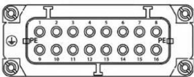
| Motor 1/5 Motor 2/6 Motor 3/7 Motor 4/8 | |||||||
| Pin Assign-ment | Pin Assign-ment | Pin Assign-ment | Pin Assign-ment | ||||
| 1 L1 5 L1 9 L1 13 L1 | |||||||
| 2 L2 6 L2 10 L2 14 L2 | |||||||
| 3 L3 7 L3 11 L3 15 L3 | |||||||
| 4 free 8 free 12 free 16 free | |||||||
5 Starting up

CAUTION!
Risk of injury due to moving loads
If people are in the work area, the loads moved by the electric chain hoists can cause injury.
While the loads are moved, nobody may be in the work area of the electric chain hoists. For persons staying under suspended loads, observe the regulations in force in your country.

NOTICE!
Damage due to change of direction
Changing the direction of movement during operation may damage the device.
Only change the position of the rotary switches if the green indicator light does not light up.

NOTICE!
Damage due to pulsed operation
Repeated, momentary presses of the [RUN] button can damage the device and the connected electric chain hoists.
Always press [RUN] for at least several seconds.
Starting up the device
-
Make sure the following:
-
Nobody stays in the work area of the electric chain hoists.
■ The workspace is free of obstacles. - You have a clear view of the entire work area and can completely monitor the movement process.
The device must not be used if not all conditions are fulfilled.
- Set all rotary switches to position '0'.
If the emergency stop button is pressed and locked: Make sure that the reason for pressing the switch is no longer present and turn it clockwise to the operating position.
-
Connect the electric chain hoists to the unit, either via the CEE sockets or via the multi-pin industrial connectors.
-
Make sure the supply voltage is correct and the three phases are connected in the correct order.
- Connect the device to the power supply.
⇒ The indicator lights [L1], [L2], [L3] for the three phases of the power supply light up. The device must not be used if not all three indicator lights light up.
- Check the correct connection and function of the electric chain hoists:
To do this, set the rotary switches for all connected electric chain hoists to the 'UP' or 'DOWN' position, the other rotary switches to the 'OFF'.
- Press [RUN] until the electric chain hoists are in the desired position.
⇒ The green indicator light is lit as long as the electric chain hoists move.
If an electric chain hoist does not move or moves in the wrong direction, it is not connected correctly.
6 Connections and controls
Front side CHC-4 (Item no. 422822)
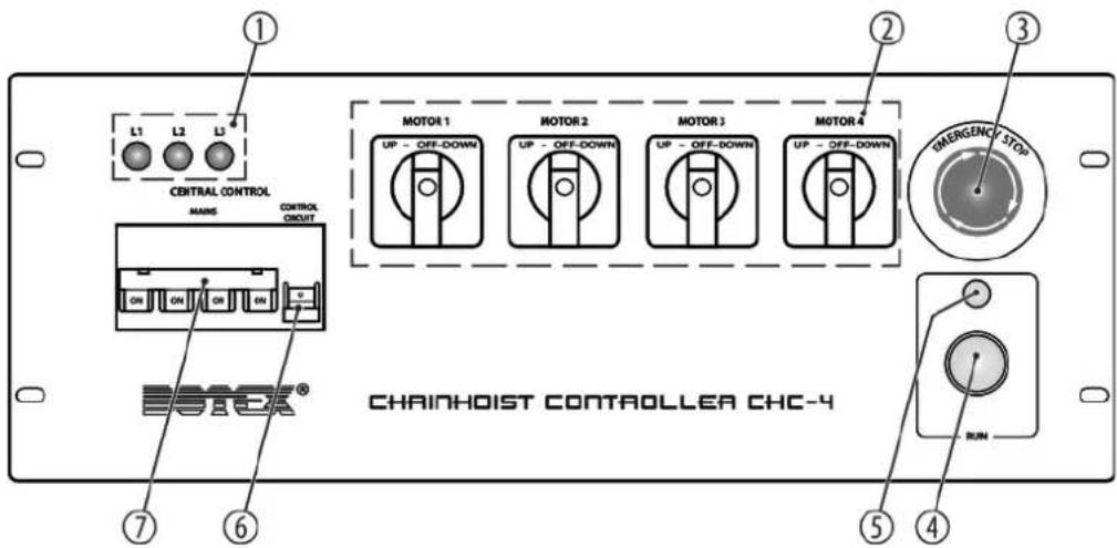
Chainhoist Controller CHC-4, CHC-8 motor controller
1 [L1], [L2], [L3]
Indicator lights for the three phases of the power supply. The device must not be used if not all three indicator lights light up.
2 [MOTOR 1]...[MOTOR 4]
Rotary switch for preselecting the direction of movement for the connected electric chain hoists 1...4.
3 [EMERGENCY STOP]
Emergency stop switch
4 [RUN]
Momentary switch for controlling the electric chain hoists whose direction of movement has been set with the [MOTOR 1]...[MOTOR 4] switches. The selected electric chain hoists run as long as the momentary switch is pressed.
5 Indicator light. Indicates that the selected electric chain hoists are running.
6 [CONTROL CIRCUIT]
Line circuit breaker for rotary switch and emergency stop switch.
7 [MAINS]
Line circuit breaker for each phase of the voltage supply.
Rear side CHC-4 (Item no. 422822)
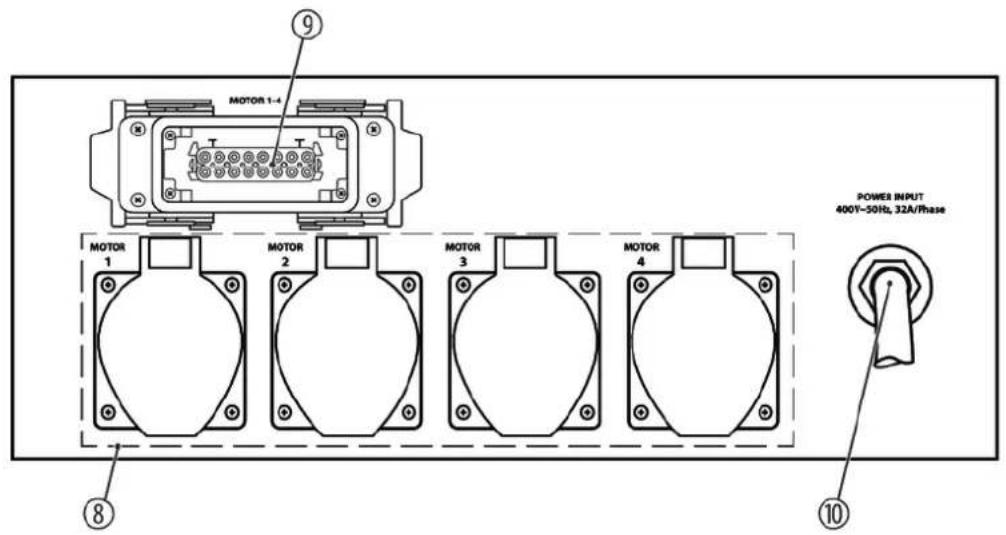
Chainhoist Controller CHC-4, CHC-8 motor controller
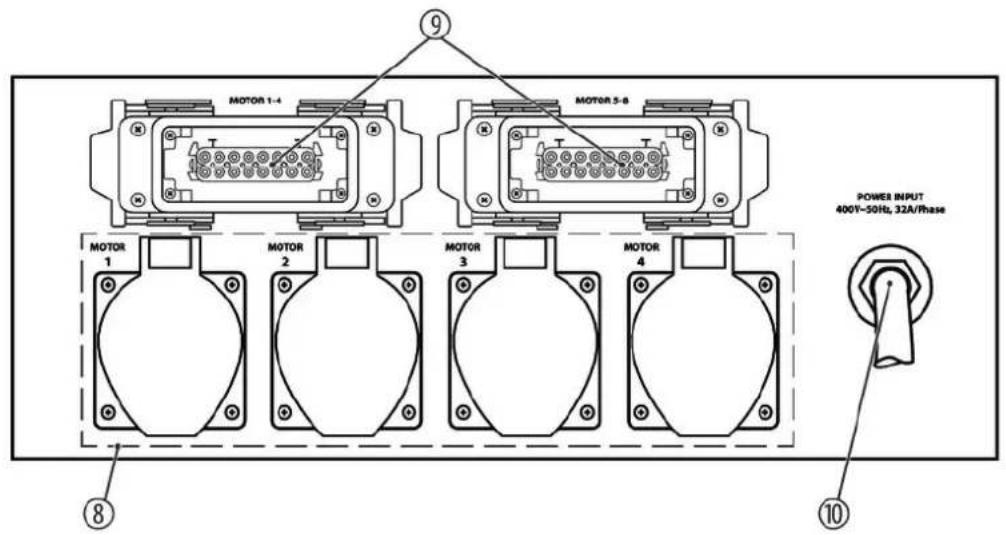
8 [MOTOR 1], [MOTOR 2], [MOTOR 3], [MOTOR 4]
CEE chassis sockets for connecting electric chain hoists 1...4.
9 16-pin multi-pin industrial connector for connecting electric chain hoists 1...4.
10 Power cable with CEE plug.
Front side CHC-8 (Item no. 422852)
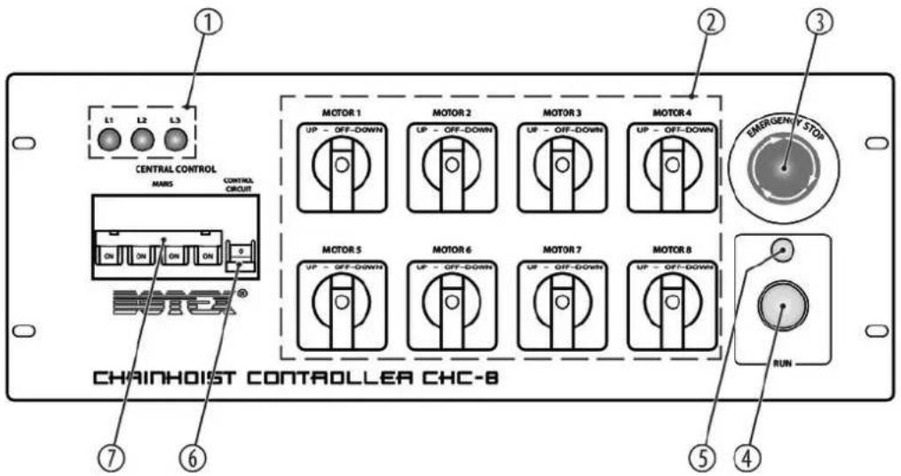
Chainhoist Controller CHC-4, CHC-8 motor controller
1 [L1], [L2], [L3]
Indicator lights for the three phases of the power supply. The device must not be used if not all three indicator lights light up.
2 [MOTOR 1]...[MOTOR 8]
Rotary switch for preselecting the direction of movement for the connected electric chain hoists 1...8.
3 [EMERGENCY STOP]
Emergency stop switch
4 [RUN]
Momentary switch for controlling the electric chain hoists whose direction of movement has been set with the [MOTOR 1]...[MOTOR 8] switches. The selected electric chain hoists run as long as the momentary switch is pressed.
5 Indicator light. Indicates that the selected electric chain hoists are running.
6 [CONTROL CIRCUIT]
Line circuit breaker for rotary switch and emergency stop switch.
7 [MAINS]
Line circuit breaker for each phase of the voltage supply.
Rear side CHC-8 (Item no. 422852)
Chainhoist Controller CHC-4, CHC-8 motor controller
8 [MOTOR 1], [MOTOR 2], [MOTOR 3], [MOTOR 4]
CEE chassis sockets for connecting electric chain hoists 1...4.
9 16-pin multi-pin industrial connector for connecting electric chain hoists 1...4 or 5...8.
10 Power cable with CEE plug.
7 Operating

CAUTION!
Risk of injury due to moving loads
If people are in the work area, the loads moved by the electric chain hoists can cause injury.
While the loads are moved, nobody may be in the work area of the electric chain hoists. For persons staying under suspended loads, observe the regulations in force in your country.

NOTICE!
Damage due to change of direction
Changing the direction of movement during operation may damage the device.
Only change the position of the rotary switches if the green indicator light does not light up.

NOTICE!
Damage due to pulsed operation
Repeated, momentary presses of the [RUN] button can damage the device and the connected electric chain hoists.
Always press [RUN] for at least several seconds.
Operating the device
-
Make sure the following:
-
Nobody stays in the work area of the electric chain hoists.
■ The workspace is free of obstacles. - You have a clear view of the entire work area and can completely monitor the movement process.
The indicator lights [L1], [L2], [L3] for the three phases of the power supply light up.
The device must not be used if not all conditions are fulfilled.
- If the emergency stop button is pressed and locked: Make sure that the reason for pressing the switch is no longer present and turn it clockwise to the operating position.
Set the rotary switches for those electric chain hoists to be moved to the 'UP' or 'DOWN' position, the other rotary switches to the 'OFF'.
- Press [RUN] until the parts moved by the electric chain hoists are in the desired position. ⇒ The green indicator light is lit as long as the electric chain hoists move.
8 Technical specifications
| CHC-4 (Item no. 422822) CHC-8 (Item no. 422852) | |||
| Line circuit breaker / phases 3 × 13 A (type D) 3 × 13 A (type D) | |||
| Line circuit breaker / rotary switch and emergency stop 6 A (type C) 6 A (type C) | |||
| Input connections Power cable with CEE plug Power cable with CEE plug | |||
| Output connections 4 × 4-pin CEE chassis socket with hinged lid | 4 × 4-pin CEE chassis socket with hinged lid | ||
| 1 × 16-pin multi-pin industrial connector for use with a breakout box | 2 × 16-pin multi-pin industrial connector for use with a breakout box | ||
| Max. load per motor switch 1.9 kW 1.9 kW | |||
| Max. load total 9 kW 9 kW | |||
| Supply voltage | 400 V ~50 Hz | ||
| Degree of protection IP20 | |||
| Installation 19", 4 RU | |||
| Dimensions (W × H × D) 483 mm × 278 mm (4 RU) × 178 mm | |||
| Weight 8.75 kg 10.3 kg | |||
| Ambient conditions Temperature range 0 °C...40 °C | |||
| Relative humidity 50 %, non condensing | |||
Circuit diagram CHC-4 (Item no. 422822)
![graph TD A["2x40VAC + N + PE 32A"] --> B["BROWN L1"] A --> C["BLK L2"] A --> D["GREY L3"] A --> E["BLUE N"] A --> F["YELLOW/GREEN PE"] A --> G["MIN/PE System"] B --> H["F1 F2 F3"] C --> I["F3A"] D --> J["F4"] E --> K["F5"] F --> L["F6"] G --> M["F7"] H --> N["RED"] I --> O["GREEN"] J --> P["Blue"] K…](/content/2026/05/819478/images/f0c1b9bc9663c44483c5e09613237a6877ecddac4bba1772bc063069631fd327.jpg)
Circuit diagram CHC-8 (Item no. 422852)
![graph TD A["3-windings AC + PE 12A"] --> B["BROWN L1"] A --> C["BLACK L2"] A --> D["GRAY L3"] A --> E["BLUE N"] A --> F["YELLOW/GREEN PE"] A --> G["NMPE Iodine"] H["RED"] --> I["F1A"] I --> J["Red"] K["F2"] --> L["F3A"] M["SEA"] --> N["F4"] O["BI"] --> P["BI1"] Q["BI2"] --> R["BI2"] S["BI3"] --> T["…](/content/2026/05/819478/images/b0bcfdc9195213e4214b8e5f90877ccb72af4d72f27a96c998065a69b7431048.jpg)
Chainhoist Controller CHC-4, CHC-8 motor controller
9 Troubleshooting
In the following we list a few common problems that may occur during operation. We give you some suggestions for easy troubleshooting:
| Symptom Remedy | |
| The electric chain hoists do not respond when [RUN] is pressed. | 1. Check the wiring to the electric chain hoists. |
| 2. Check whether the assigned rotary switch is in ‘UP’ or ‘DOWN’ position. | |
| 3. Check that the circuit breaker is in ‘ON’ position. | |
| 4. If the emergency stop button is pressed and locked: Make sure that the reason for pressing the switch is no longer present and turn it clockwise to the operating position. | |
| The device does not respond at all. 1. Check the mains connection and the main fuse. | |
If the procedures recommended above do not succeed, please contact our Service Center. You can find the contact information at www.thomann.de.
10 Protecting the environment
Disposal of the packaging material

For the transport and protective packaging, environmentally friendly materials have been chosen that can be supplied to normal recycling.
Ensure that plastic bags, packaging, etc. are properly disposed of.
Do not just dispose of these materials with your normal household waste, but make sure that they are collected for recycling. Please follow the notes and markings on the packaging.
Disposal of your old device
This product is subject to the European Waste Electrical and Electronic Equipment Directive (WEEE) in its currently valid version. Do not dispose with your normal household waste.
Dispose of this device through an approved waste disposal firm or through your local waste facility. When discarding the device, comply with the rules and regulations that apply in your country. If in doubt, consult your local waste disposal facility.
Notes


- TABLE OF CONTENTS
- 1 GENERAL INFORMATION
- 1.1 FURTHER INFORMATION
- 1.2 NOTATIONAL CONVENTIONS
- LETTERINGS
- DISPLAYS
- INSTRUCTIONS
- EXAMPLE
- 1.3 SYMBOLS AND SIGNAL WORDS
- 2 SAFETY INSTRUCTIONS
- SAFETY
- DANGER
- DANGER FOR CHILDREN
- ELECTRIC SHOCK CAUSED BY HIGH VOLTAGES INSIDE
- ELECTRIC SHOCK CAUSED BY SHORT CIRCUIT
- HAZARDOUS VOLTAGE
- NOTICE
- RISK OF FIRE
- OPERATING CONDITIONS
- POWER SUPPLY
- 3 FEATURES
- 4 INSTALLATION
- 4.1 MECHANICAL INSTALLATION
- RACK MOUNTING
- 4.2 ELECTRICAL INSTALLATION
- PIN ASSIGNMENT
- 5 STARTING UP
- CAUTION
- DAMAGE DUE TO PULSED OPERATION
- STARTING UP THE DEVICE
- 6 CONNECTIONS AND CONTROLS
- 7 OPERATING
- OPERATING THE DEVICE
- 9 TROUBLESHOOTING
- 10 PROTECTING THE ENVIRONMENT
Brand : Botex
Model : Chainhoist Controller CHC-4
Category : Lighting