
Diamond 10.3 - Loudspeaker Wharfedale - Free user manual and instructions
Find the device manual for free Diamond 10.3 Wharfedale in PDF.


| Product Type | Floorstanding loudspeaker |
| Model | Diamond 10.3 |
| Brand | Wharfedale |
| Bass Driver | 125 mm woven Kevlar cone |
| Tweeter | 25 mm soft dome |
| Recommended Amplifier Power | 20 - 100 W |
| Impedance (Nominal) | 6 Ω |
| Sensitivity | 85 dB (2.83V @ 1m) |
| Frequency Range | 40 Hz - 24 kHz |
| HF Limit (-10 dB) | 44 kHz |
| Crossover Frequency | 1.6 kHz |
| Dimensions (H x W x D) | 800 x 194 x 278 mm (31.5 x 7.6 x 10.9 in) |
| Height with Spikes | 853 mm (33.6 in) |
| Weight | Approximately 13 kg (28.7 lb) each |
| Finish | Sealed wood veneer, available in multiple finishes |
| Grille | Removable, fabric |
| Bi-Wire / Bi-Amp Capable | Yes (dual terminals with metal links) |
| Spikes Included | Yes, lockable spikes plus rubber feet for wood floors |
| Magnetic Shielding | No |
| Recommended Placement | At least 200 mm from rear wall, 700 mm from side walls |
| Included Accessories | Spikes, rubber feet, locknuts, user manual |
Frequently Asked Questions - Diamond 10.3 Wharfedale
User questions about Diamond 10.3 Wharfedale
0 question about this device. Answer the ones you know or ask your own.
Ask a new question about this device
Download the instructions for your Loudspeaker in PDF format for free! Find your manual Diamond 10.3 - Wharfedale and take your electronic device back in hand. On this page are published all the documents necessary for the use of your device. Diamond 10.3 by Wharfedale.
USER MANUAL Diamond 10.3 Wharfedale
DIAMOND 10 SERIES


User Cautions

IMPORTANT SAFETY INFORMATION
Read these instructions.
read all warnings
Follow instructions.
Do not use this apparatus near water.
Clean only with dry cloth
Dollar exceeding transaction benefits.
Do not install near any heat sources such as radiators, heat registers, stoves, or other apparatus (including amplicons) that produce heat.
Do not restrict the safety purpose of the polarized or grounding type plug. A polarized plug has two blades with one wider than the other. A grounding type plug has two blades and a third-grounding proing. The wider side of the third prope are provided for your safety. If the provided plug does not think your car, consult an electric fan from power to the obstruction area. Protect the power cord from being walked on or pinched, particularly at plugs, convenience susceptives, and the point where they exit from the apparatus.
Use only attachments/accessories specified by the manufacturer.
Use only with a can, stuff, induct, brock, or table specified by the manufacturer, or sold with the apparatus. When a can is used, use caution when moving the can/apparent combination to avoid injury from top over. Unplug this apparatus during tightening storm or when amused for long periods of time.
Referral servicing to qualified service personnel. Serving is required when the apparatus has been damaged in any way such as power supply cord or drug is damaged, liquid has been spilled or objects have fallen into the apparatus, the apparatus has been exposed to rain or moisture; does not operate normally or has been dropped.
Warning to reduce the cost of the electric shock, not exceed this product to rain or moisture. The product must not be enclosed to shipping and splashing and no effect. The with liquids such as a waste of iron ore should be placed on the product.
Nominal Temperature, such as candles should be placed on the product. Caption: Changes or modifications not expressly approved by the manufacturer could void the user's authority to operate this device.
SUBWOOFER INFORMATION
Warning The main power switch for this appliance is located on the rear panel. Top permit free access to this switch, the apparatus must be located in an open area without any obstructions.
ELECTRICAL CLASS:
10.SX-SUB; 10.MX-SUB

CLASSDouble insulated
This product must not be connected to Earth
10.GX-SUB
THIS APPLIANCE MUST BE EARTHED

This symbol indicates that there are
instructors in the literature accompanying this out.

This symbol indicates that dangerous
voltage continuing a risk of electric shock is present within this unit.
This equipment has been tested and found to comply with the limits for a Class B digital device, pursuant to part '15 of the FCC Rules. These limits are designed to provide reasonable protection against harmful interference in a residential installation.
This equipment generates, uses and can radiate radio frequency energy and, if not installed and used in accordance with the instructions, may cause harmful interference to radio communications. However, there is no guarantee that interference will not occur in a particular installation. If the equipment cites cause harmful interference to radio or television reception, which can be determined by turning the equipment off and on, the user is encouraged to try to correct the interference by one or more of the following measures:
• Reason to relocate the receiving internet
• Increase the separation between the equipment and receiver format at the end of the end.
- Can't get the position, and it is a key to break down format to which the receiver is connected.
• Consult the dealer or an experienced radio/TV technician for help
IMPORTANT NOTICE TO UK USERS
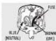
The power command your subwoofer may be supplied with a plug incorporating a fuse, the value of which is indicated on the pin face of the plug. Should the fuse need to be replaced, an A51A or 60 approved I51362 fuse must be used of the same rating. If the plug is cut-off it must NOT be re-used. Dispose of any such plug safety. There is a danger of electric shock if a cut-off plug is inserted into a main socket.
Connecting a Mains Plug
The words in the main lead are colored in accordance with the code.
Blue NEUTRAL, Blowel, ME: Green Yellow Sea Earth
As these colours may not correspond to the coloured markings identifying the terminals in your plug, proceed as follows:
10.GX SUB
The BLUE wire must be connected to the terminal marked with the letter N or coloured BLUE or BACK. The BROWN wire must be connected to the terminal marked with the letter L or coloured BROWN or RED. The GREEN/YELLOW wire must be connected to the terminal marked with the letter E or coloured GREENormarkwide symbol
10.SX-SUB:10.MX-SUB
The BLUE wire must be connected to the terminal marked with the letter N or coloured BLUE or BLACK. The BROWN wire must be connected to the terminal marked with the letter L or coloured BROWN or RED.

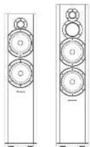


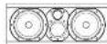


" shown with optional floor stand
Produced after 13th August 2005.
Waste electrical products should not be disposed of with household waste. Please recycle where facilities exist.
Check with your Loca Authority or retail for recycling advice.


Specifications
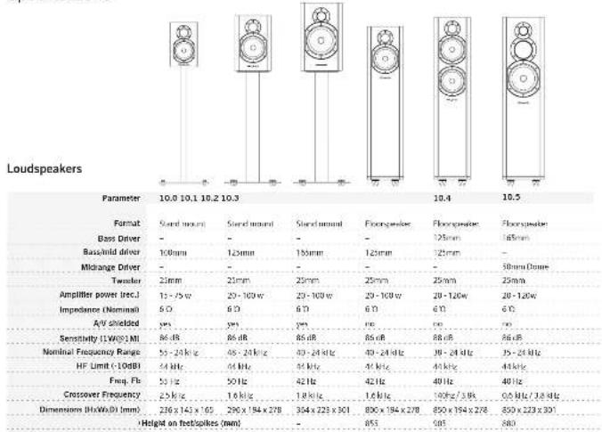
other
Loudspeakers | Parameter | 10.0 | 10.1 | 10.2 | 10.3 | 10.4 | 10.5 | |---|---|---|---|---|---|---| | Format | Stand mount | Stand mount | Stand mount | Floorspeaker | Floorspeaker | Floorspeaker | | Bass Driver | - | - | - | - | 125mm | 165mm | | Bass/Ind driver | 100mm | 120mm | 155mm | 125mm | 125mm | - | | Midrange Driver | - | - | - | - | - | 50mm D###e | | Twender | 2mm | 2mm | 25mm | 25mm | 25mm | 25mm | | Amplifier power (rec.) | 12-75w | 20-100w | 23-100w | 29-100w | 20-120w | 20-120w | | Impedance (Nominal) | 6Ω | 6Ω | 6Ω | 6Ω | 6Ω | 6Ω | | A/V Shielded | yes | yes | yes | no | no | no | | Sensitivity (LW@0.1 ML) | 86 dB | 86 dB | 85 dB | 85 dB | 88 dB | 86 dB | | Nominal Frequency Range | 55-24 kHz | 45-24 kHz | 40-24 kHz | 40-24 kHz | 39-24 kHz | 35-24 kHz | | HF Limit (10dB) | 44 kHz | 44 kHz | 44 kHz | 44 kHz | 44 kHz | 44 kHz | | Freq. Fb. | 50 Hz | 50 Hz | 42 Hz | 42 Hz | 40 Hz | 40 Hz | | Crossover Frequency | 2.5 kHz | 1.6 kHz | 1.8 kHz | 1.6 kHz | 160Hz / 3.9Hz | 0.6 MHz / 3.8 kHz | | Dimensions (kHz:0.1 mm) | 236 x 143 x 165 | 290 x 194 x 278 | 304 x 223 x 301 | 800 x 194 x 278 | 850 x 194 x 278 | 850 x 223 x 301 | | Height on headcounts (mm) | - | - | - | 853 | 985 | 980 | The chart is a table with the dimensions of the speaker's size in nanometers and corresponding frequency values for each component. The data is presented in a table format with columns for 'Parameter' and 'Format'.*10.0,10.1,10.2 models show with options if floors and
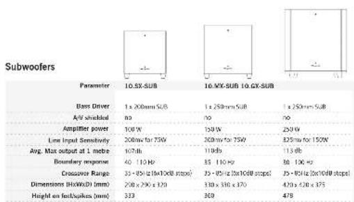
Specifications table to change without notice. EAGE
Contents
Cautons 2
Good Practice Guide....3
Unpacking the Equipment 4
Fitting the Spikes....4
Cables and Connectors ....
Crossovers 5
Positioning the Front Loudspeakers....6
Positioning the Centre Loudspeaker 6
Positioning and attaching Surround Loudspeakers....7
Connecting the Front Loudspeakers ....B
Connecting the Centre and Surround Lou speakers....9
Diamond 10 Subwoolers 10
Connecting your Subwoofer....11
Operating your Subwoofer 13
Fine Tuning your Subwoofer 14
Setting Up a Home Theatre System 15
Troubleshooting 16
Care, Service and Warranty 17
Specifications 18-19
Good Practice Guide
Before connecting and using your loudspeakers, please bear the following points in mind:
Switch off the amplifier and all sources before making connections to your sound system. When you switch on the system or change sources, set the volume control to minimum and turn up the level gradually.
The position of your Volume Control is NOT a reliable guide as to the maximum capabilities of your sound system. Playing the system with extreme settings of volume and tone controls may damage the amplifier and loudspeakers.
Do not connect loudspeaker terminals to the mains supply.
- Ensure that your loudspeakers are correctly wired and are in phase.
Do not subject your loudspeakers to excessive cold, heat or sunlight.
- If you are shelf mounting your loudspeakers, make sure they are not placed on the same shelf as your source components.
Do not place heavy objects on top of loudspeaker cabinets. If you play the loudspeakers with the grilles removed be careful to protect the drive units from children and pets.
Do not use makeshift stands. Always fit a manufacturer's approved stand using the instructions and the fixings provided. Your dealer will advise you.
Do not attempt to dismantle the loudspeaker. There are no user serviceable parts inside and you will invalidate the warranty.
Some Front and all Centre loudspeakers are magnetically screened. You should site front loudspeakers at least 0.5 m away from TV sets and magnetic storage media. All Wharfedale centre loudspeakers may be sited close to a TV screen with no adverse effects. The specifications on Pages 20 and 21 have AV shielding details for your loudspeakers.
- When connecting your loudspeakers, do not run cable across areas of open floor where they may be a source of danger. Run them safely around room boundaries if necessary.


Preliminaries
Unpacking Your Loudspeakers
Diamond 10 loudspeakers come in many shapes and sizes. If you are unpacking the larger loudspeakers or a
subwoofer, please remember that these units are heavy. We suggest that you have someone to assist you.
- Lift the loudspeaker carefully out of the packing. Do NOT try and lift the loudspeaker using the protective bag.
- Unpack any accessories carefully
- If there is any sign of damage or if the contents are incomplete, report this to your dealer as soon as possible.
- Retain the packing for future safe transport of the product. If you dispose of the packing, do so with respect to any recycling provisions in your area
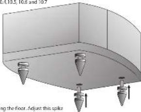
Attaching the Spikes to Floorstanding Models - 10.3, 10.4, 10.5, 10.6 and 10.7
- Make sure you have plenty of unobstructed working space
- Place a soft cloth on the floor to protect the loudspeaker.
- Invert the loudspeaker onto the cloth.
e Thread a locknut onto each spike and loosely run it up the thread - Thread the spikes onto the spike inserts, Tighten them finger tight.
- Invert the loudspeaker. Be careful not to damage the floor with the splices.
Levelling the Loudspeakers
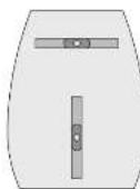
- When the speaker is upright: You
will probably find that the speaker will wobble with one spike not contacting the floor. Adjust this spike until all four spikes are on the floor. - With the aid of a spirit level move each spike in and put until the loudspeaker is
level and sitting squarely on all four spikes with no rocking. - Now tighten each locknut securely against the collar in the pinth
to secure the spike - Screw in rubber feet are provided for use on wood or stone floors etc. and should be attached in the same manner as the spires.
natural_image
3D diagram of a mechanical component with three conical protrusions and a curved base, no text or symbols present.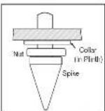
Stands and Brackets
The 10.1 and 10.2 loudspeakers are intended primarily for stand mounting, though they can be mounted on wall brackets or even on sturdy shelves. The quality of loudspeaker stands greatly influences the performance of your loudspeakers so do not use flimsy products.
The 10.0 may best stand or wall mounted. The rear panel has a threaded insert for attaching a pair of suitable wall brackets.
CentreChannelLoudspeakers
Each centre channel loudspeaker is supplied with two sets of mounting feet. By using a combination of large and small feet the loudspeaker may be angled to point directly at the listening position. This will be found useful when the centre speaker is positioned under the TV screen.
Surround Loudspeakers
These speakers are designed primarily for wall mounting, though they may be stand or shelf mounted if required. Please see Page7.
Looking After Your Loudspeaker
- Your Loudspeakers use a specially sealed finish. They should not be waxed or treated with spray polishes which will smear and dim the finish. Occasionally polish them with a dry or barely moist cloth to remove dust and finger marks, etc.
- If you play the speakers with the grilles off exercise great care, NEVER operate speakers with the grilles off if there are children or pets in the house.
- Occasionally, remove the loudspeaker grilles and brush them gently with a soft brush before replacing them.
- NEVER use a vacuum cleaner to clean loudspeaker grilles.
- NEVER stand objects on your loudspeakers. In particular do not stand flowers etc on them - they are not jardinieres!
- Avoid getting any liquid behind the grille. If you accidentally spill liquid on your loudspeakers, take them to your dealer for attention before using them again.
- Do not open the speakers; there are no user serviceable parts inside.
- Never touch the drive units either with an object or your hands.
Quality Assurance
Your loudspeakers have been constructed to the highest standards. From the top grade furniture construction and finish to the carefully designed and selected acoustic components our speakers are built to provide a lifetime of sonic pleasure. We hope you will derive many years of good service from our products.
Servicing
In the unlikely even that your unit develops a fault you should return it to your Wharledale dealer using the original packing to ensure safe shipping.
The terms of your guarantee may vary in different countries but in all cases the guarantee excludes:
- Liability for damage or loss occurring in transit to or from the purchaser.
- All damage caused through accident, misuse, wear and tear, neglect, incorrect installation, adjustment or repair by unauthorised personnel.
- Liability for damage or loss occurring in transit to or from the purchaser.
- Whartedale will not be liable for any consequential damage, loss or injury, arising from or in conjunction with this equipment.
Service Addresses
For technical support, servicing or product quotes and information please contact either your local retailer or the offices below.
UK
Asia
IAG Service Dept
145
Lrit4
Room 2510-2511 Press Building.
St. Margaret's Way
Sherman Road C
Ji Keely, 2014
Shenzhen
+ ymb
Tel: 08-15-51031200
PL29500
Fax: -06-755-02091205
Tel: 44 (0)1489 452551
Fax: +411011482 413603
For information on other authorised service centres worldwide contact Wharfedale international in the U.K.
A worldwide distributor list is available on the Wharfedale website: www.wharfedale.co.uk


Delay and LFE Settings
The purpose of delay is to enable surround and dialogue information to arrive at the listener's ears at the same time as the Front channels, even when the listening seat is in a non-ideal position.
Rear Delay: If the listening position is equidistant from the Front and Rear speakers, a low delay setting should be set. The closer the listener is to the Rear speakers the higher should be the delay setting used.
Centre Delay: If the Centre speaker is level with (or slightly behind) the Front speakers, set the delay to zero. If the Centre speaker is forward of the Front speakers, increase the delay.
LFE in domestic systems the LFE channel typically feeds into the subwoofer. Where no subwoofer is used, the LFE signal is combined with Front Channel information. When you set the LFE level at your AV processor, use care as the powerful low frequencies can overload domestic loudspeakers. If you hear popping or thumping noises coming from the front loudspeakers or subwoofer, immediately turn the AV Processor's volume level down and then back off the LFE level. This should cure the problem. If it does not, back off the volume level at the subwoofer (if you are using one) until the problem disappears.
Please read the relevant sections of your AV amplifier manual and familiarise yourself with the various issues. If you are unsure, consult your dealer for help.
Troubleshooting
If your system is not working properly please work through this checklist before returning a unit to your dealer. Before investigating a problem, always switch off the system at the mains.
No Sound:
The system is not switched on. Speaker cables are shorting terminals out. The wrong source is selected.
The sound lacks bass content: Bass reproduction indistinct:
The front loudspeakers are out of phase. The subwoofer is not switched on,
The subwoster phase is incorrectly set. The subwoster crossover control is set top low.
Excessive bass distortion at low volumes:
The subwoofer level is set too high. The LFE level is set too high. The subwoofer is incorrectly wired.
Excessive or distorted bass at high levels:
The system level is set too high. The bass control is set too high. The speakers are too close to room corners.
Distorted or rattling sounds at high levels:
System level too high. Objects on speakers/subwoofer. Objects too close to subwoofer
Popping or thumping from the subwoofer:
The system level is set too high. The subwafer level is set too high. The LFE level is set too high.
Indistinct sound: Poor localisation of effects. Poor localisation of dialogue.
One or more loudspeakers is out of phase. (Read the manual for correct connection procedure).
Television picture colour is distorted: (Conventional CRT screens only)
The subwoofer is too close to the TV. (Switch off the system and TV. Move the units apart. Switch on after 15 min.)
Cables and Connectors
Choosing Loudspeaker Cable
Specialist audio cable usually offers better performance than general purpose 'bell' or 'zip' wire.
Choose a cable of suitable diameter - cable that is too thin will limit, the dynamics of the sound and may impair the bass response. Audio cable is polarised, with two cores of different colours, or often a raised rib or coloured tracer in the case of twin cable. Before you purchase your cable, give careful thought to the positioning of your loudspeakers. This is especially the case if you are bi-viring your loudspeakers.
Cable lengths to loudspeaker pairs should be the same for left and right channels in order to equalise the signal transmission. Allow some slack in your speaker cables so you can alter their position to best advantage.
Preparing Loudspeaker Cable
Split the twin cores to a depth of about 40mm. Carefully strip the insulation from each end, leaving about 10mm of bare wire. If the cable is stranded, lightly twist to gather any loose strands.
Connecting Screw Terminals
All the loudspeakers use screw terminals.
Unscrew the terminal. Insert the bare end of the cable into the hole in the base of the terminal. Tighten securely.
When connecting terminals make sure you leave no strands of bare wire that can short across to adjacent terminals.
As an alternative to bare wire you can use specialist spade connectors. Your Whartedale dealer will be pleased to advise you.

Crossover Networks
Bi-Wireable Networks
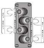
Most speakers in the Diamond 10 series use a special bi-hireable crossover panel with four terminal binding posts. Please follow the drawing carefully to see the correct orientation of the loudspeaker terminals. The upper terminals connect to the treble unit, the lower pair to the bass unit. As supplied, the treble terminal pair is connected to the bass terminal pair via removable metal straps. Those should be left in place for standard installations.
Why Bi-Wire?
Using separate cables for treble and bass units in a Bi-Wiring configuration reduces intermodulation effects and improves headroom and clarity. To be-wire, you will need to install two lengths of twin core cable between the amplifier and each loudspeaker.
Standard Networks
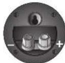
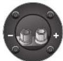
The D10.0 compact monitor, the D10.CC compact Centre Channel speaker and the D10.SR use similar circular section two terminal crossover panels. The D10.DFS uses a crossover network panel built into the speaker's rear wall. This is illustrated on Page 7.
None of the above loudspeakers are bi-vireable.
D10.SR
D10.0 & D10.CC


Positioning the Front Loudspeakers
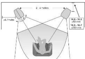
The 10.3, 10.4, 10.5, 10.6 and 10.7 models are designed to be floor standing. We suggest that they are positioned at least 200 mm from the rear walls and 700 mm from the side walls, facing slightly inwards. The 10.1, and 10.2 models should be stand or wall mounted though they may be placed on a rigid shelf. The 10.3 model can be stand or wall mounted. The bass extension will improve if the small speakers are operated closer to the rear wall.
If the loudspeakers are placed too close to the walls the bass will increase but may be boamy and indistinct. If the loudspeakers are placed away from the walls, the inward angle may be increased by up to 40%, although this may restrict the width of the optimum listening position.
A useful rule of thumb is that the listener should be as far from the loudspeakers as they are from each other. The speakers should ideally be positioned so that the treble units are roughly as far level to a seated listener. As personal taste plays a large role, experiment with different configurations and play a wide range of programmes before finalising the position of your speakers.
Positioning the Centre Loudspeaker
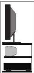
The Centre channel loudspeaker should be positioned centrally between the loudspeakers, close to the television and mounted above or below the screen.
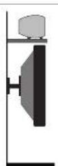
The loudspeaker should be located on a stable flat surface to avoid any cabinet movement at high sound levels. If you mount the unit above the television, move it forward so that the front grille sits slightly in front of the screen. This will reduce sound reflections from the screen and the top of the cabinet.
Centre channels speakers are supplied with a set of four self-adhesive mounting feet and two extra feet. Remove the protective backing from four feet. Place the feet at the bottom of the cabinet. Attach each foot 10 mm in from the sides of the cabinet and place them so that the cabinet is supported in a horizontal position with the curve of the cabinet clear of the shelf. The extra feet enable you to tilt the cabinet up or down so that the speaker points directly at the listening position. This facility is particularly useful if the speaker is mounted under the screen.
A custom stand is available for the D10 CM which allows the loudspeaker to be positioned under a wall-mounted monitor and has an adjustable vertical tilt for optimal dispersion.
Setting Up a Home Theatre System
Some of this chapter may appear to react the content of the Subwoofer pages - the context however is different.
Placement
Front And Effects Channels: The front loudspeakers are placed on other side of the television screen, 2 to 3 metres apart. The speakers should be angled slightly so they are aimed towards the listeners.
We recommend placing the rear effects speakers in a high position, behind the listener's head. If the rear or side walls are a long way from the listening seat, consider stand mounting the loudspeakers. If the centre loudspeaker is very high or low, angle it towards the listener's ear level. The front faces of the centre and surround loudspeakers should also be in line as far as possible.
Subwoofer: As the ear is unable to detect the direction from which deep bass originates, you have freedom to position the unit. Varying the distance from the wall alters the bass. Placing the subwoofer across a corner boosts the bass but may impair clarity. The performance of Home Theatre systems is enhanced by using two subwoofer.
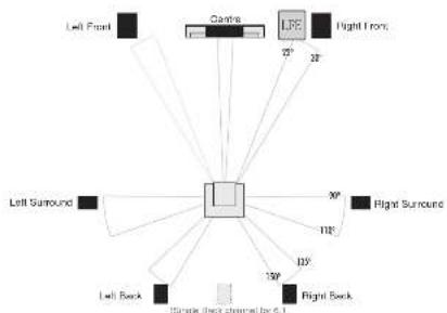
6.1 and 7.1 System Placement
Dolby Labs, DTS and THX offer 6.1 and 7.1 formats. Although the precise configuration of these systems will depend on the capabilities of your processor and you should be guided by those instructions, we would make some observations.
For 6.1 and 7.1 formats the listening seat should not be too close to the rear wall.
Optimising the time delay so that information from all speakers arrives at the listening seat coherently is critical if the benefits of these systems are to be fully realised.
Dolby Labs Recommended Placement for Multichannel Home Theatre Systems
flowchart
graph TD
    A["Left Front"] --> B["Centre"]
    B --> C["LRF"]
    C --> D["Right Front"]
    E["Left Surround"] --> F["Central"]
    F --> G["Flight Surround"]
    H["Left Back"] --> I["120°"]
    J["Flight Back"] --> K["118°"]
    L["30°"] --> M["30°"]
    N["120°"] --> O["120°"]
    P["Simple Back channel by 6.1"] --> Q["Ground"]
Setting Loudspeaker Sizes and Levels
If you are not using a subwoofer: Set the Front Speakers to 'Large'. Set the 'Subwoofer' option on the processor to Off or 'No'. The Front channels will now receive all the system bass.
If you are using a subwoofer: When set to 'Small' all the system bass will go into the subwoofer. If you choose 'Large' the Front channel bass will be reproduced from the Front speakers. Follow the instructions on the previous page for suitable size and crossover settings.
Once the loudspeaker settings have been finalised, put the AW amplifier into its "Test" mode and adjust the level of each channel until all channels are reproduced at equal loudness. You may need to adjust the subwoofer output level. Avoid setting too high a level or you will swamp the sound with bass which be tiring to listen to and may limit the subwoofer's ability to respond to large bass transients. Set a sensible level going into the subwoofer. The subwoofer volume control should be between 12 o'clock and 3 o'clock


Fine Tuning Procedures
Set up the subwoofer with all tone controls and filters on your amplifier or processor set "flat".
Listening rooms are not ideal. Because of room geometry and construction there will be areas with severe peaks at some frequencies and severe troughs at others. If you side loudspeakers in such areas the response will be highly non-flat. It is easier to treat high frequency irregularities by the use of drapes, soft furnishings etc., but very hard to do the same at bass frequencies due to the very long wavelengths.
To help locate standing waves in your listening room, one idea is to sit in the listening seat and recruit a friend with a deep voice to speak as he moves around the area where you propose to site your subwoofer - you will soon find out where taste it: Where the voice sounds most natural is a good place to start.
Although the subwoofer's bass output is enhanced by walls or corners, so often is coloration. The floor will influence the sound. The surface under the subwoofer should be stable and unobstructed. If the carpet is very thick, consider placing the subwoofer on a solid surface such as a marble slab. If you place the subwoofer where it amplifies the irregularities of the room or the main speakers the result will be bloated, coloured bass, if acoustic guitar and make voice sounds coloured when the subwoofer is operating at normal level and less coloured if the subwoofer volume is reduced, you need to address the positioning first before adjusting any controls.
Loudspeaker Phasing: Make sure that all loudspeakers are connected in phase, if there is a doubt about the way the loudspeakers are connected, check their phasing by playing a mano source. The sound should appear from a point midway between the front loudspeakers. If this position is indefinite, reverse the connections to one speaker. Correctly connected loudspeakers give a definite centre sound source with fuller bodied tenor and bass registers.
Setting the Phase of the Subwoofer: Phase at very low frequencies is not straightforward to detect. Initially we suggest you temporarily set the low bass filter to highest setting and the phase to 0° and play some bass heavy music in Stereo through the main speakers and the subwoofer. From the listening position, switch the phase between 0° and 180°. The setting which appears to give the greater bass output is correct. Now follow the instructions below for setting the Crossover filter.
Setting Loudspeaker Sizes: Most digital AV Processors ask you to specify the size of speakers in the various channels. These are usually Large or 'Small'. This sets the bass management for the system.
Front Loudspeakers: The larger door standing loudspeakers (10.4, 10.5, 10.6 and 10.7) can be set to 'Large'. Smaller loudspeakers (including stand mounted units) should be set to 'Small' The 10.3 should be set to small. If the bass is excessive, then set the loudspeaker to 'Large'.
Centre and Surround channels: The D10. EM centre channel speaker should be set to LARGE. The other centre channel speakers and the surround channel speakers should be set to 'SMALL' so that bass from these channels will be directed to the subwoofer. Set the 'Subwoofer' option on the processor to 'On' or 'Yes'.
Crossover Control: If you are using a digital AV processor the initial subwoofer setting should be 8.5Hz as the processor will have its own bass management system. After experimenting with various sources you may need to adjust the Subwoofer Crossover settings. Try to ensure the subwoofer blends into the sound stage - the more invisible the subwoofer component of the sound field is, the better.
Setting levels: Once the loudspeaker settings have been finalised, put the AV amplifier into its "Test" mode (see instructions supplied with your processor). Adjust the levels until all channels are reproduced at equal loudness. When adjusting the subwoofer output level avoid setting too high a level or you will swamp the sound with bass which be ting to listen to and may limit the subwoofer's ability to respond to large bass transients. Set a sensible level going in the subwoofer from the processor.
Positioning Surround Loudspeakers
D10 DFS Surround Loudspeakers
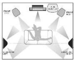
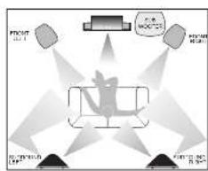
The speakers should ideally be sited 600 mm-1.5 metres above the listening position and 2.5-3.5 metres apart, central to the listener and behind the listening position, preferably on a rear wall. If the listening position is some distance from a rear wall, the speakers may be mounted on opposite side walls but always behind the listening position.
Ensure that the wall is sound and can support the product. Drill two 5mm holes in the wall 220mm apart. Fix a suitable No 8 round head screw firmly into each hole using appropriate wall plugs. Leave a stub of 5mm protruding from the wall.
Connect the loudspeakers. Align the holes in the mounting brackets over the screw and carefully lower the unit onto the screws. The speaker should now be securely attached with the spacers resting against the wall. Now connect the speakers to the amplifier.
Note: As an alternative, the D10 DFS can be shelf or stand mounted. The badge on the D10 DFS can be rotated to match the orientation of the loudspeaker.
Alternative 5.1 System Layouts with D10 DFS Surrounds
flowchart
graph TD
    A["PROCT"] --> B["LPT"]
    C["PROCT"] --> D["PROCT"]
    E["PROCT"] --> F["PROCT"]
    G["PROCT"] --> H["PROCT"]
    I["PROCT"] --> J["PROCT"]
    K["PROCT"] --> L["PROCT"]
    M["PROCT"] --> N["PROCT"]
    O["PROCT"] --> P["PROCT"]
    Q["PROCT"] --> R["PROCT"]
    S["PROCT"] --> T["PROCT"]
    U["PROCT"] --> V["PROCT"]
    W["PROCT"] --> X["PROCT"]
    Y["PROCT"] --> Z["PROCT"]
D10 SR Surround Loudspeakers
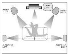
Before mounting the loudspeakers, establish the location using the same criteria as for the D10, DFS. The D10 SR is supplied with four mounting feet for shelf or stand mounting. The terminal panel has a built-in mounting slot for well fixing.
Wall mounting the D10 SR:
Ensure the wall is sound and can easily support the weight of the loudspeakers. Drill and fix a No. 8 screw and suitable wall plug at each chosen location. The screw should protrude about 5mm from the wall. Connect the cable to the speaker. Align the keyhole slot over the screw. Full gently down to secure the speaker.
Alternative 5.1 System Layouts with D10 SR Surrounds
Connecting the Front Loudspeakers
Standard Connection
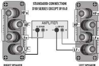
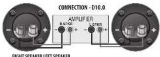
Choose a suitable length of twin core speaker cable for each channel, and prepare the ends. Unscrew each terminal a few turns.
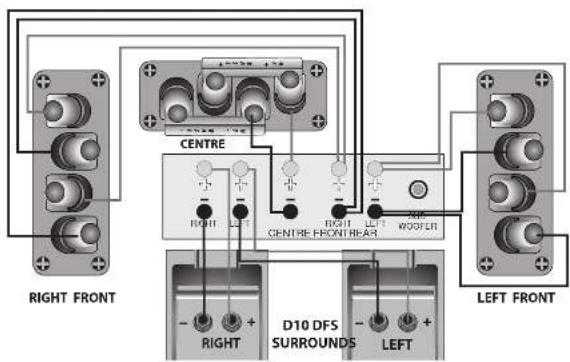
Connect the red, positive (−) terminal of the Left loudspeaker to the corresponding red, positive (−) amplifier terminal. Connect the black, negative (−) terminals similarly. Tighten the terminals securely. Repeat this procedure for the Right Channel.
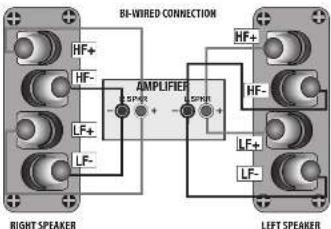
Bi-Wiring
Using separate cables for treble and bass units in a BI-Wiring configuration reduces intermodulation effects and improves headroom and clarity. To bi-wire, you will need to install two equal lengths of twin core cable between the amplifier and each loudspeaker.
Unscrew each terminal a few turns and remove the metal straps. Connect the cables between the amplifier and the loudspeakers as indicated above and re-tighten all the terminals securely.
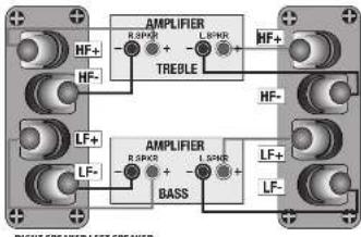
Bi-Ampifying (Bi-Amping)
By connecting each loudspeaker drive unit to its own dedicated amplifier the advantages of EI-Wiring can be extended.
If you own two identical stereo power amplifiers, your speakers may be 3i Amped. For further details please consult your dealer.
Check that all connections to the subwoofer have been properly made and that the main volume control is at minimum. Plug the supplied power cord into the mains socket on the rear panel.
Initial Settings
Volume Control: Set the subwoofer volume control to the mid position (12 o'clock) before proceeding. Crossover Control: This control should initially be sat to 45 or 55 Hz when the subwoofer is used with small bookshelf speakers and to 35 or 40 Hz when used with large floor standing speakers.
Phase Switch: The Phase switch should be initially set to 0°.
Switching On
Plug in the mains plug and switch the power on. Now switch the subwoofer on with the rest of your system. The subwoofer ON/OFF switch has a rocker action press "I" to switch the equipment on and "O" to switch it off. When switched on the light beside the power switch and the light on the front of the subwoofer will glow and the subwoofer will be operational.
Basic Tuning
Volume Setting: Play a programme with extended bass and set the system volume to a reasonable level. Adjust the subwoofer volume control to produce the desired level of bass. The bass should be even and an extension of the main loudspeakers. Do not set the control too high or you will swamp the sound with too much bass and clarity and definition will suffer.
Phase Switch: If the bass is indistinct or lacks depth, the Phase switch may need adjustment. Set the switch to 0° and listen carefully to some music with extended bass. If there is insufficient bass output from the sub waver set the Phase switch to 180°. Select the position which produces the most natural, extended bass.
Crossover Adjustment. This adjusts the blend between the subwoofer and the main speakers and enables the system to be set up for optimum bass performance. The higher settings are for use with small bookshelf loudspeakers, the lower settings for large floorstanding models. If you choose too low a setting with small speakers, there will be a 'hole' in the bass response too high a setting with large speakers will result in the upper bass becoming bloated. See the next section for further details.
Again the subwoofer should be an extension of the main loudspeakers.
Mains Operation
When the system is not in use for extended periods, we suggest you switch off the subwoofer to protect it from switching noises caused by domestic appliances, etc. The best practice is to switch the complete system on and off from a central point. Bear in mind that if you play the system with the subwoofer switched off you will get no bass!
Autopower Switch. (Diamond 10, SX-SUB, 10.MX-SUB) If the subwoofer is left permanently on this may result in low level turn or noise from the subwoofer when the rest of the system is switched off. Setting the AUTO switch to ON will automatically turn the subwoofer on when a signal is detected at any of the inputs and turn it off (Standley Mode) after a period of inactivity. We recommend that the AUTO switch be set to ON for normal operation.
In AUTO mode, when the subwoofer is switched on, the subwoofer will become active. If there is no audio input present the subwoofer will go immediately into Standby. As soon as an audio input is detected the subwoofer will then switch on.
When the system is not in use for extended periods, we suggest you switch off the subwoofer to protect it from switching noises caused by domestic appliances, etc.
Always turn the main volume control to minimum when you switch the system on or off.


Connecting Your Subwoofer - 2
Connecting to a Digital AV Processor
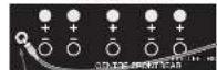
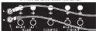
If your AV processor has a line level or LE subwoofer output you should use this connection. You will need to purchase a single screened RCA photo lead from your dealer. Connect this lead to the Left line input of the Subwoofer as shown.
Alternatively, you may use a split mono lead from the processor to both inputs of the subwoofer. In this case the input level at the subwoofer will be slightly higher.
Stereo Line Level Connections
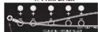
If your amplifier has a sparse preamplifier output or a stereo sub-woofer output, connect the sub-woofer as shown.
You will need a stereo screened RCA phone cable. Connect a stereo RCA phone cable from the line output of the prama to the Subwoofer line Inputs.
PreOut-MainInConnections
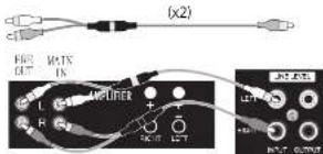
If you use a separate stereo paw and power amplifier, or an amplifier where the pre and main amplifier can be separated, connect the subwoofer as shown. There are two alternative methods.
Using a Y Adaptor
You will need two screened RCA Y' adaptors and two single RCA phone cables. Remove the Pre Main links on your amplifier. Connect the socket (common of an RCA Y' adaptor to one of the mono cables. Connect one leg of the Y' adaptor to the Left Channel Pre Out socket on the amplifier and the other leg to the Left Channel Main in socket. Connect the remaining plug on this combination to the Left Channel Line Level input on the sub-woofer. Request this for the Right Channel.
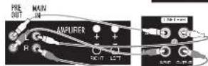
Placing the Subwoofer in the System Loop
You will need two stereo for four single screen RLCA cables. Connect a Stereo cable from the Line Level Inputs of the sub-woofer to the Pre-Out sockets of the amplifier. Now connect a second Stereo cable from the Line Level Outputs of the sub-woofer to the Main in sockets of the amplifier. Make sure that the Right and Left Channels are not mixed up. The sub-woofer is now inserted within the system loop.
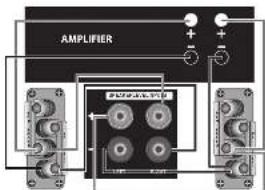
High Level (loudspeaker) Connections
You will need two additional lengths of Loudspeaker cable.
Ensure the Front lounspeakers are correctly connected.
Connect the Left Speaker Terminals on the sub bass unit to the Front Left speaker terminals on the amplifier. Connect the Red (-) speaker terminal on the amplifier to the Red (-) terminal on the subwoofer. Connect the Black (-) speaker terminal on the amplifier to the Black (-) Terminal on the subwoofer.
Now connect the Right Speaker terminals on the subwoofer to the Front Right speaker terminals on the amplifier.
NOTE: High level connection should be used ONLY when line level connections are not feasible.
A-V AMPLIFIER
Subwoofer Cut (Line Level)

A-V AMPLIFIER
Subwoofer Out (Line Level)

AV AMPUER/STEREO AMPUER
Subwoofer or Pre-Dut [Line Level]

FRONT LEFTFRONT RIGHT
Connecting Centre and Surround Loudspeakers
Connect these speakers as shown below. The Centre channel speaker may be connected as shown, or bi-wired.
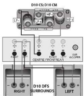
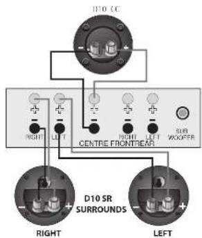
Multichannel 5.1 System Connections
12
6


Diamond 10 Subwoofers
Introduction
Wharfedale subwoofer are intended for use with high quality domestic sound systems. They are equally effective in Stereo and Home Cinema applications. Your subwoofer will probably be used in conjunction with Wharfedale loudspeakers though they will partner any audiophic or top quality home cinema amplification and loudspeakers.
Unpacking your Subwoofer
Open the carton and remove all the top packing pieces. Lift the subwoofer out taking care not to damage the cabinet. When lifting the unit from the carton support it from the bottom, DO NOT attempt to lift the subwoofer out of the carton using the protective bag. The unit is heavy, if you cannot manage it easily, get someone to assist you.
Preparing the Subwoofer
Diamond 10. SX-SUB and 10. MX-SUB: No further preparation is necessary. Diamond 10. GX-SUB: You should attach the spikes or protective rubber feet to the subwoofer.
Carefully invert the subwoofer. Protect the top by placing it on a soft surface such as a towel. Open the protective bag and slide it part-way down the cabinet. Two sets of adjustable screw feet are provided - regular and spiked. Choose one set only - do not use a mixture of spliced and regular feet.
Screw the threaded washer over each foot as shown. Screw a foot part-way into the threaded hole at the bottom of each leg of the subwoofer and hand-tighten the washer. When all four screw feet have been fitted, stand the subwoofer
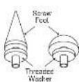
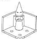
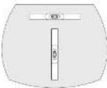
With the aid of a spirit level, screw each foot in and out until the subwoofer is level (side to side and front to back) and firmly supported on all four feet. Tighten the washer with a wrench to lock the assembly in position.
Note: When using spiked feet take care not to drag the subwoofer and be careful not to pierce objects or cables which may be hidden under carpets, etc. Spikes are not suitable for use with stone floors and can cause damage to wood floors, so consider carefully before deciding which feet to use.
Positioning the Subwoofer
Although the unit may be placed almost anywhere in the room, we recommend that it be placed in front of the listener and as control to the listening position as possible. There should be a mains outlet within easy reach. The subwoofer should not be operated within 450mm of a television set as the drive unit magnet may distort the picture. The bass unit is mounted underneath the subwoofer and moves a lot of air at high volume, so make sure the floor is sound. Do not place the subwoofer with the bass port near surfaces or objects that may rattle.
We suggest you initially position the subwoofer about 20cm (8 inches) from the wall. Placing the unit close to the wall will enhance the bass; placing it across the corner of the room will increase the bass further, possibly at the expense of clarity.
Experiment with locations and sources before making a final decision.
Before Connecting the Subwoofer
Switch off your amplifier and all connected source units at the mains. Unplug the power cords if necessary.
Make sure the subconverter is disconnected from the mains and that the ON/OFF switch is OFF.
Before re-connecting your system to the AC power supply, check that all the connections are properly made.
- Signal cables should be properly terminated and fully screened to minimise harm. If you connect your subwoofer via the low level signal inputs, the cable between your control unit or processor and the subwoofer could be quite long so screening is particularly important. Consult your dealer if in doubt.
Connecting Your Subwoofer - 1
DIAMOND 10. GX SUB REAR PANEL
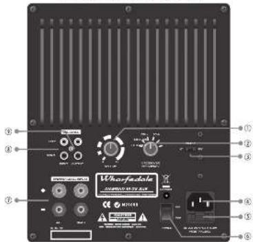
Subcofer Volume Control
② Crossover frequency Control
⑤ Phase Control
IFC Mains Input Soccer
(5) Mains Power Fuse
⑤ Mans Power Switch
⑦ Speaker Level Inputs
① Line Level Inputs
⑤ Line Level Outputs
DIAMOND 10. MX-SUB REAR PANEL
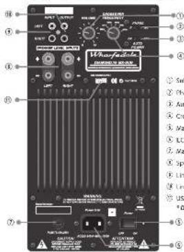
DIAMOND 10. SX-SUB REAR PANEL
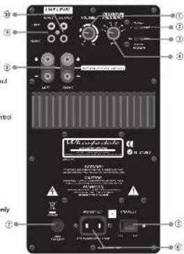

All three subcenters feature the same connectivity.
The 10. MIX-Sub has one additional feature - a USB power supply ① for charging the internal battery of an optional wireless receiver. This receiver enables a Subwoofer to receive signals from a suitably equipped AV amplifier or processor without the need for a signal input interconnect. Consult your Wharfdale dealer for details.


- DIAMOND 10 SERIES
- User Cautions
- IMPORTANT SAFETY INFORMATION
- SUBWOOFER INFORMATION
- ELECTRICAL CLASS:
- 10.SX-SUB; 10.MX-SUB
- IMPORTANT NOTICE TO UK USERS
- Connecting a Mains Plug
- 10.GX SUB
- 10.SX-SUB:10.MX-SUB
- Contents
- Good Practice Guide
- Preliminaries
- Unpacking Your Loudspeakers
- Stands and Brackets
- CentreChannelLoudspeakers
- Surround Loudspeakers
- Looking After Your Loudspeaker
- Quality Assurance
- Servicing
- Service Addresses
- Delay and LFE Settings
- Troubleshooting
- Cables and Connectors
- Choosing Loudspeaker Cable
- Preparing Loudspeaker Cable
- Connecting Screw Terminals
- Crossover Networks
- Bi-Wireable Networks
- Standard Networks
- Positioning the Front Loudspeakers
- Positioning the Centre Loudspeaker
- Setting Up a Home Theatre System
- Placement
- and 7.1 System Placement
- Setting Loudspeaker Sizes and Levels
- Fine Tuning Procedures
- Positioning Surround Loudspeakers
- Connecting the Front Loudspeakers
- Standard Connection
- Bi-Wiring
- Bi-Ampifying (Bi-Amping)
- Initial Settings
- Switching On
- Basic Tuning
- Mains Operation
- Connecting Your Subwoofer - 2
- Connecting to a Digital AV Processor
- Stereo Line Level Connections
- PreOut-MainInConnections
- Using a Y Adaptor
- Placing the Subwoofer in the System Loop
- High Level (loudspeaker) Connections
- Connecting Centre and Surround Loudspeakers
- Diamond 10 Subwoofers
- Unpacking your Subwoofer
- Preparing the Subwoofer
- Positioning the Subwoofer
- Before Connecting the Subwoofer
Brand : Wharfedale
Model : Diamond 10.3
Category : Loudspeaker