
TPC-1551WP - Desktop computer Advantech - Free user manual and instructions
Find the device manual for free TPC-1551WP Advantech in PDF.


| Product Type | Industrial Touch Panel Computer |
| Model | TPC-1551WP |
| Brand | Advantech |
| Display Size | 15.6" TFT LED LCD |
| Resolution | 1366 x 768 (WXGA) |
| Luminance | 300 cd/m² |
| Contrast Ratio | 500:1 |
| Touch Technology | Projected Capacitive, Tempered Glass |
| Touch Resolution | 2048 x 2048 |
| CPU | Intel Atom E3827 1.75 GHz |
| BIOS | AMI UEFI |
| Memory | 8 GB DDR3L (maximum) |
| Storage | 1x CFast slot, optional 2.5" SATA HDD/SSD |
| I/O Ports | RS-232 x1, RS-232/422/485 x1, USB 3.0 x1, USB 2.0 x1, LAN (10/100/1000) x2 |
| Expansion | Full-size Mini PCIe slot x1 |
| Power Input | 24V DC ±20%, typical 2.0A |
| Dimensions (W x H x D) | 419.7 x 269 x 61.9 mm |
| Cutout Dimensions | 412.4 x 261.7 mm |
| Weight | 5 kg |
| Operating Temperature | 0 to 55°C |
| Storage Temperature | -20 to 60°C |
| Humidity | 10-95% @ 40°C (non-condensing) |
| Ingress Protection | IP66 (front bezel) |
| Cooling | Fanless |
| Certifications | FCC Class A, CE |
| Warranty | 2 years |
Frequently Asked Questions - TPC-1551WP Advantech
User questions about TPC-1551WP Advantech
0 question about this device. Answer the ones you know or ask your own.
Ask a new question about this device
Download the instructions for your Desktop computer in PDF format for free! Find your manual TPC-1551WP - Advantech and take your electronic device back in hand. On this page are published all the documents necessary for the use of your device. TPC-1551WP by Advantech.
USER MANUAL TPC-1551WP Advantech
natural_image
Illustration of three kitchen appliances in green outline style (no text or symbols)TPC-1051WP/1551WP Series
Industrial Touch Panel Computers with Intel® Atom™ Processors
Copyright
The documentation and the software included with this product are copyrighted 2014 by Advantech Co., Ltd. All rights are reserved. Advantech Co., Ltd. reserves the right to make improvements in the products described in this manual at any time without notice. No part of this manual may be reproduced, copied, translated or transmitted in any form or by any means without the prior written permission of Advantech Co., Ltd. Information provided in this manual is intended to be accurate and reliable. However, Advantech Co., Ltd. assumes no responsibility for its use, nor for any infringements of the rights of third parties, which may result from its use.
Acknowledgements
Intel and Atom are trademarks of Intel Corporation.
Microsoft Windows and MS-DOS are registered trademarks of Microsoft Corp.
All other product names or trademarks are properties of their respective owners.
This Manual Covers the Following Models:
■ TPC-1051WP-E3 Series
■ TPC-1551WP-E3 Series
Part No. xxxxxxxxxxxxxxx Edition 1
Printed in Taiwan July 2015
Product Warranty (2 years)
Advantech warrants to you, the original purchaser, that each of its products will be free from defects in materials and workmanship for two years from the date of purchase.
This warranty does not apply to any products which have been repaired or altered by persons other than repair personnel authorized by Advantech, or which have been subject to misuse, abuse, accident or improper installation. Advantech assumes no liability under the terms of this warranty as a consequence of such events.
Because of Advantech's high quality-control standards and rigorous testing, most of our customers never need to use our repair service. If an Advantech product is defective, it will be repaired or replaced at no charge during the warranty period. For out-of-warranty repairs, you will be billed according to the cost of replacement materials, service time and freight. Please consult your dealer for more details.
If you think you have a defective product, follow these steps:
- Collect all the information about the problem encountered. (For example, CPU speed, Advantech products used, other hardware and software used, etc.) Note anything abnormal and list any onscreen messages you get when the problem occurs.
- Call your dealer and describe the problem. Please have your manual, product, and any helpful information readily available.
- If your product is diagnosed as defective, obtain an RMA (return merchandise authorization) number from your dealer. This allows us to process your return more quickly.
- Carefully pack the defective product, a fully-completed Repair and Replacement Order Card and a photocopy proof of purchase date (such as your sales receipt) in a shippable container. A product returned without proof of the purchase date is not eligible for warranty service.
- Write the RMA number visibly on the outside of the package and ship it prepaid to your dealer.
Declaration of Conformity
CE
This product has passed the CE test for environmental specifications when shielded cables are used for external wiring. We recommend the use of shielded cables. This kind of cable is available from Advantech. Please contact your local supplier for ordering information.
FCC Class A
Note: This equipment has been tested and found to comply with the limits for a Class A digital device, pursuant to part 15 of the FCC Rules. These limits are designed to provide reasonable protection against harmful interference when the equipment is operated in a commercial environment. This equipment generates, uses, and can radiate radio frequency energy and, if not installed and used in accordance with the instruction manual, may cause harmful interference to radio communications. Operation of this equipment in a residential area is likely to cause harmful interference in which case the user will be required to correct the interference at his own expense.
Technical Support and Assistance
- Visit the Advantech web site at http://support.advantech.com where you can find the latest information about the product.
- Contact your distributor, sales representative, or Advantech's customer service center for technical support if you need additional assistance. Please have the following information ready before you call:
– Product name and serial number
– Description of your peripheral attachments
– Description of your software (operating system, version, application software, etc.)
– A complete description of the problem
– The exact wording of any error messages
Safety Instructions
- Read these safety instructions carefully.
- Keep this User Manual for later reference.
- Disconnect this equipment from any AC outlet before cleaning. Use a damp cloth. Do not use liquid or spray detergents for cleaning.
- For plug-in equipment, the power outlet socket must be located near the equipment and must be easily accessible.
- Keep this equipment away from humidity.
- Put this equipment on a reliable surface during installation. Dropping it or letting it fall may cause damage.
- The openings on the enclosure are for air convection. Protect the equipment from overheating. DO NOT COVER THE OPENINGS.
- Make sure the voltage of the power source is correct before connecting the equipment to the power outlet.
- Position the power cord so that people cannot step on it. Do not place anything over the power cord.
- All cautions and warnings on the equipment should be noted.
- If the equipment is not used for a long time, disconnect it from the power source to avoid damage by transient overvoltage.
- Never pour any liquid into an opening. This may cause fire or electrical shock.
- Never open the equipment. For safety reasons, the equipment should be opened only by qualified service personnel.
- If one of the following situations arises, get the equipment checked by service personnel:
■ The power cord or plug is damaged.
- Liquid has penetrated into the equipment.
■ The equipment has been exposed to moisture.
The equipment does not work well, or you cannot get it to work according to the user's manual.
■ The equipment has been dropped and damaged.
■ The equipment has obvious signs of breakage.
-
DO NOT LEAVE THIS EQUIPMENT IN AN ENVIRONMENT WHERE THE STORAGE TEMPERATURE MAY GO BELOW -20°C (-4°F) OR ABOVE 60°C (140°F). THIS COULD DAMAGE THE EQUIPMENT. THE EQUIPMENT SHOULD BE IN A CONTROLLED ENVIRONMENT.
-
CAUTION: DANGER OF EXPLOSION IF BATTERY IS INCORRECTLY REPLACED. REPLACE ONLY WITH THE SAME OR EQUIVALENT TYPE RECOMMENDED BY THE MANUFACTURER, DISCARD USED BATTERIES ACCORDING TO THE MANUFACTURER'S INSTRUCTIONS.
The sound pressure level at the operator's position according to IEC 704-1:1982 is no more than 70 dB (A).
DISCLAIMER: This set of instructions is given according to IEC 704-1. Advantech disclaims all responsibility for the accuracy of any statements contained herein.
Caution!

Danger of explosion if battery is incorrectly replaced. Replace only with the same or equivalent type recommended by the manufacturer. Dispose of used batteries according to the manufacturer's instructions.
Chapter 1 General Information ....1
1.1 Introduction ...... 2
1.2 Specifications 2
1.2.1 System Kernel.... 2
1.2.2 I/O Ports.... 2
1.2.3 O/S support.... 2
1.2.4 Safety and Environment.... 3
1.3 LCD Specifications.... 3
1.4 Touchscreen Specifications 4
1.5 Power 4
1.6 I/O Ports Arrangement 4
Figure 1.1 I/O Port Arrangement .... 4
1.7 Panel Mounting 5
1.8 Dimensions and Cutout.... 5
Figure 1.2 TPC-1051WP Dimensions....6
Figure 1.3 TPC-1551WP Dimensions....7
Chapter 2 System Setup....9
2.1 System Setup.... 10
Figure 2.1 Unpack the Package 10
Figure 2.2 Install CFast Memory Card (Mylar in accessory box can be attached to CFast card for easy extraction)....11
Figure 2.3 Power Connector and Power Lines ...... 11
Figure 2.4 Power Receptor & Button Pin Assignment .... 12
2.1.1 Installing the Drivers 12
2.2 Transport and Unpacking.... 13
2.3 Panel Mounting 13
2.4 Cabinet Installation and Earth Grounding setup 14
2.5 Power/Digital Ground and Earth Ground 16
Chapter 3 Features in Windows Embedded .....17
3.1 Features in Windows Embedded 18
3.2 Enhanced Write Filter (EWF) 18
3.3 File-Based Write Filter (FBWF) 20
3.4 HORM 21
Appendix A Serial Port Settings 23
A.1 Jumper, Dip switch and Connector location.... 24
A.1.1 Top....24
A.1.2 Bottom.... 24
A.2 Jumper setting and Description.... 25
A.2.1 CMOS Clear Function (CN1) 25
A.3 Switch Setting 25
A.3.1 Termination Resistor Select (SW3).... 26
A.4 Connector Pin Definition 26
A.4.1 SATA connector (CN12) 26
A.4.2 SATA Power connector (CN13) 27
A.4.3 Mini PCIE slot (MINIPCIE) 27
A.4.4 CFast slot (CN14) 28
A.4.5 Power in connector (CN18).... 28
A.4.6 LAN RJ45 connector (CN7,CN8) 29
A.4.7 USB connector (CN10) 30
A.4.8 COM1 RS232 connector (CN15) 30
A.4.9 COM2 RS232/422/485 connector (CN16) 31
Appendix B Driver Installation and Configuration..
33
B.1 Intel Chipset Software Installation Utility Installation.... 34
B.2 Intel Graphics Driver Installation 36
B.3 LAN Driver Installation 39
B.4 Intel® Trusted Execution Engine Driver Installation.... 42
B.5 Windows 7 USB 3.0 Driver Installation 46
B.6 Advantech EC Driver Installation 49
B.7 Advantech EC Brightness Control Tool Installation 51
B.8 Advantech EC Watchdog Timer Driver Installation.... 53
B.9 Advantech LMsensor Driver Installation 57
Appendix C BIOS Setup 59
C.1 Entering Setup 60
C.1.1 Main Setup....61
C.1.2 Advanced BIOS Features Setup.... 62
C.1.3 Chipset Configuration 72
C.1.4 Security....73
C.1.5 Boot 74
C.1.6 Save & Exit 75
Chapter 1
General Information
1.1 Introduction
The TPC-1051WP/TPC-1551WP Touch Panel Computers are state-of-the-art Human Machine Interfaces featuring 10.1" & 15.6" displays with Intel Atom™ E3827 1.75 GHz Processor
The key features are as follows:
■ True-flat touch screen
TPC-xx51WP series are true-flat touch screen designed with IP66 front protection.
Fanless
By using a low-power processor, the system does not have to rely on fans, which often are unreliable and causes dust to circulate inside the equipment.
■ Wide operating temperature
TPC-1051WP support -20\~55°C and the TPC-1551WP support 0-55°C wide operating temperature solution to provide flexibility in harsh environments.
Bright Display
The TFT LED LCD display suits industrial demands for clear interfaces. Wide Operating Temperature & Isolation Protection.
1.2 Specifications
1.2.1 System Kernel
CPU: Intel® Atom™ E3827 1.75 GHz Processor
BIOS: AMI UEFI BIOS
VGA: Integrated in Intel® Atom™ E3827
Ethernet: 10/100/1000Base-T x 2
■ Watchdog Timer: EC watchdog timer; 1.0 second timeout period
Storage:
CFast slot x 1
2.5" SATA HDD/SSD slot x 1 (optional, accessory TPC-1251T-EHKE required)
1.2.2 I/O Ports
■ RS-232 x 1, RS-232/422/485 x 1
USB 3.0 x 1
USB 2.0 x 1
■ Full-size Mini PCIe Card x1
1.2.3 O/S support
■ Microsoft® Windows
- WES7 32bit/64bit
– Win EMB 8.1 Industry Pro
- Windows 7 32bit/64bit
- Windows 8 64bit
(see Appendix C for BIOS setup before installing Windows 8.X)
1.2.4 Safety and Environment
Safety
FCC Class A
CE certificated
The front bezel is compliant with IP66 for true flat models and IP65 for the TPCs with the traditional front bezel
Environment
■ Operating Temperature:
- TPC-1051WP: -20\~55°C (-4 \~ 131°F)
- TPC-1551WP: 0-55°C(32\~131°F)
■ Storage Temperature:
- TPC-1051WP: -30-70°C (-22 \~ 158°F)
- TPC-1551WP:-20-60°C(-4 \~ 140°F)
■ Humidity: 40°C @ 10\~95% relative humidity (non-condensing)
Vibration:
With CFast: 2 Grms (5\~500 Hz)
With HDD: 1 Grms (5 \~ 500 Hz)
(Operating, random vibration)
1.3 LCD Specifications
| TPC-1051WP Series TPC-1551WP Series | ||
| Display Type TFT LED LCD TFT LED LCD | ||
| Size 10.1" 15.6" | ||
| Maximum Resolution 1280 x 800 (WXGA) 1366 x 768 (WXGA) | ||
| Maximum Colors 262K | 16.7m | |
| Viewing Angle (CR≥10) | 170°/170° | 170°/160° |
| Luminance (cd / m2) | 300 | 300 |
| Contrast Ratio | 1300:1 | 500:1 |
| Operating Temperature | -20~55°C | 0~55°C |
| Backlight Lifetime | 25,000 hours | 50,000 hours |
| Backlight | LED | LED |
Note! There might be several bright or dark pixels on the LCD. This phenomenon is normal in today's LCD manufacturing. Inspection criteria are following specifications defined by LCD vendor.
1.4 Touchscreen Specifications
■ Touch Type: Projected Capacitive Touch
■ Base Glass Construction: Tempered glass
■ Resolution: 2048 x 2048
Light Transmission: 90% ± 3% (Measured by BYK-Gardner)
■ Controller: USB Interface
1.5 Power
■ Input Voltage: 24V_DC +/- 20% (the fuse will become an open circuit if the input level exceeds 32 V_DC )
■ Typical: 24 V _DC @ 1.5Amp for TPC-1051WP, 2.0Amp for TPC-1551WP
1.6 I/O Ports Arrangement
The arrangement of the I/O ports is shown in Figure 1.1
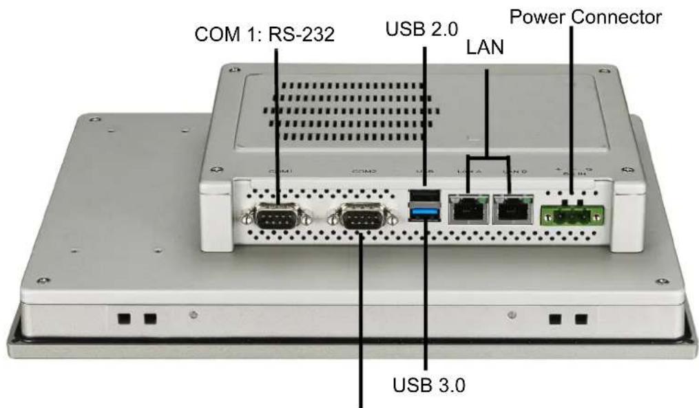
COM 2: RS-232/RS-422/RS-485
Figure 1.1 I/O Port Arrangement
1.7 Panel Mounting
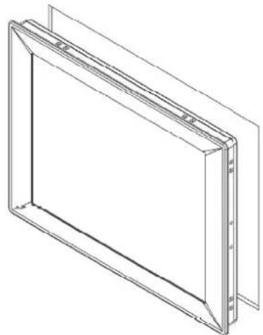
- There is a rubber waterproof gasket on the AL front bezel. Make sure the waterproof gasket is in position before installing TPC into the panel opening.
- Install the TPC into the panel opening.
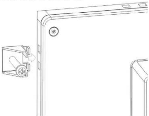
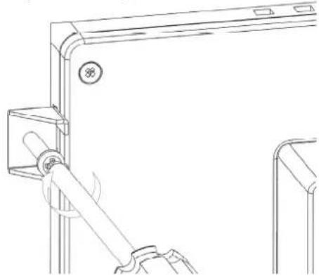
- Take the clamps and long screws from the accessory box. Hook the clamps to the holes around the four sides of the bezel. Insert the screws into every clamp and fasten them. These screws will push the mounting panel and fix the unit.
- The suggested mounting panel thickness is less than 6 mm (0.236").
1.8 Dimensions and Cutout
TPC-1051WP Series
Weight: 2.56 kg
■ Dimensions (W x H x D): 283.1 x 202.3 x 61.4 mm (11.15" x 7.96" x 2.42)
■ Cutout: 274.6 (+/- 0.4mm) x 193.8(+/-0.7mm)
TPC-1551WP Series
Weight: 5 kg
■ Dimensions (W x H x D): 419.7 x 269 x 61.9mm (16.52" x 10.59" x 2.44")
■ Cutout: 412.4(+/-0.4mm) x 261.7(+/-0.7mm)
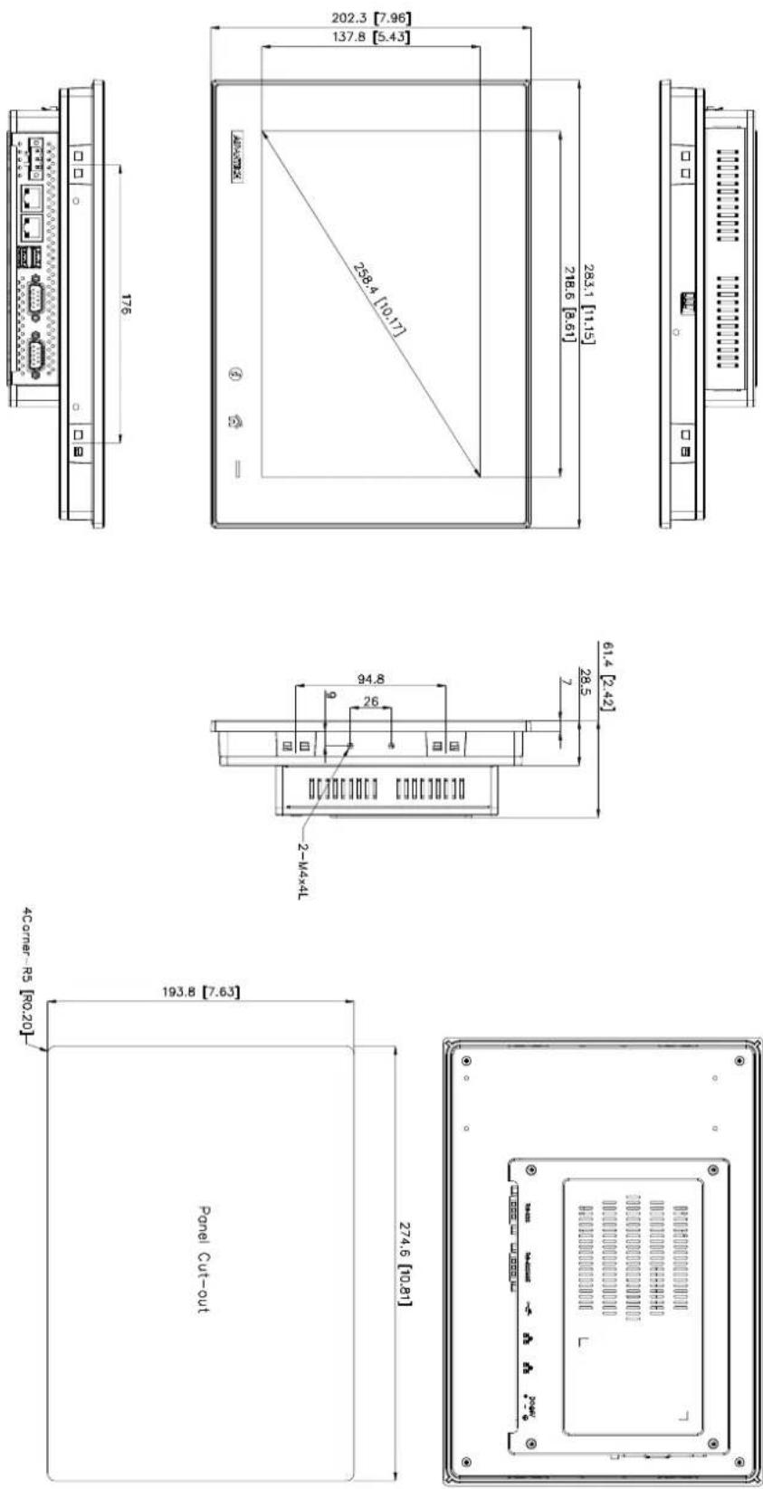
Figure 1.2 TPC-1051WP Dimensions
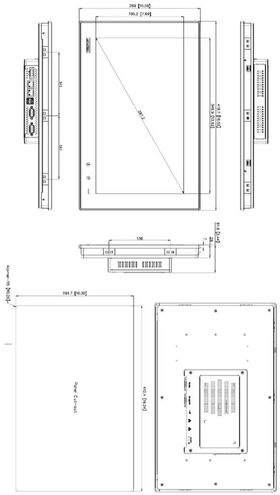
Figure 1.3 TPC-1551WP Dimensions
Chapter 2
System Setup
2.1 System Setup
You can easily get TPC started by following the below steps.
- Unpack the TPC package. Check the packing list at the beginning of this manual to make sure all items have been included.
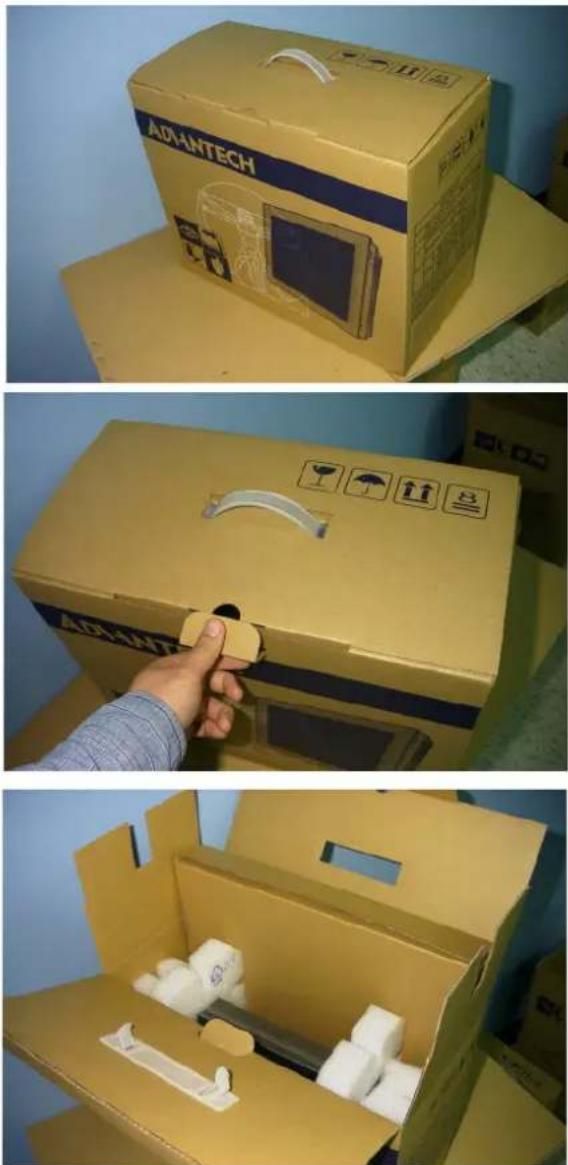
natural_image
Three-panel photo showing a yellow cardboard box with 'AIDANTECH' branding, a hand adjusting a button, and an open cardboard box containing white plastic components (no text or symbols visible)Figure 2.1 Unpack the Package
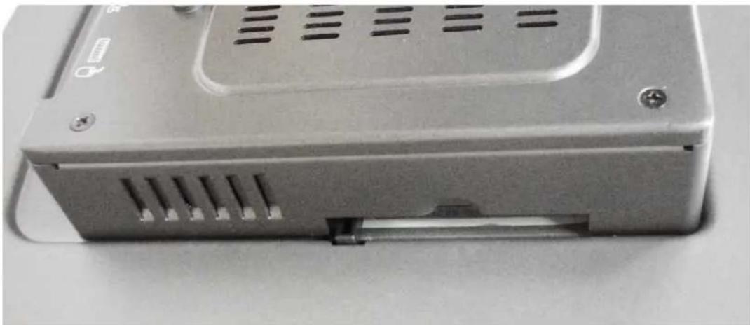
- Install a CFast ^® card containing the operating system.
natural_image
Close-up of a silver electronic device casing with ventilation slots and mounting holes (no visible text or symbols)Figure 2.2 Install CFast Memory Card
(Mylar in accessory box can be attached to CFast card for easy extraction)
Warning!! It is suggested to turn OFF system power as you plug in or pull out the memory card, even though the CompactFlash memory is hot swappable.

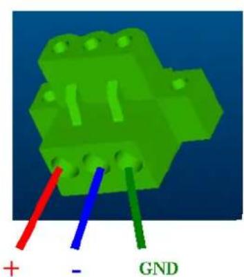
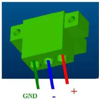
- Connect the power connector to the 24 V DC power lines. The power lines can either be of some power adapter or in-house power source.
natural_image
3D diagram of a green electronic component with three colored pins (blue, red, green) and label 'GND' at bottom (no other text or symbols)Figure 2.3 Power Connector and Power Lines
natural_image
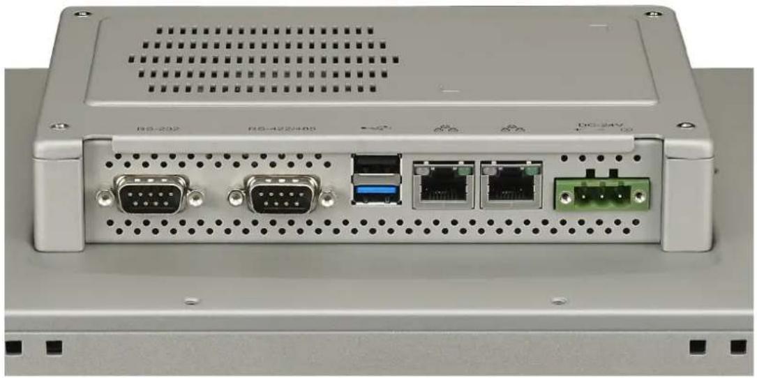
Back panel of a server rack with multiple ports and connectors (no visible text or labels)Figure 2.4 Power Receptor & Button Pin Assignment
-
Plug the power lines into the system power receptor.
-
Supply power to the system
2.1.1 Installing the Drivers
After installing your system software, you will be able to set up the Ethernet, VGA, and touchscreen functions. All drivers are stored in a CDROM disc entitled "TPC-1051WP, TPC-1551WP" which can be found in your accessory box.
The various drivers in the CD-ROM disc have their own text files which help users install the drivers and understand their functions. These files are a very useful supplement to the information in this manual.
Note!

The drivers and utilities used for the TPC-1051WP, TPC-1551WP panel PCs are subject to change without notice. If in doubt, check Advantech's website or contact our application engineers for the latest information regarding drivers and utilities.
2.2 Transport and Unpacking
When accepting a delivery, please check the packaging for visible transport damage and check the delivery for completeness by comparing it with your order. If you notice any shipping damage or inconsistencies between the contents and your order, please inform the responsible delivery service immediately.
During transport, the TPC should be protected from excessive mechanical stress. If the TPC is transported or stored without packaging, shocks, vibrations, pressure and moisture may impact the unprotected unit. A damaged packaging indicates that ambient conditions have already had a massive impact on the device. Therefore, please use the original packaging during transportation and storage.
If the TPC is transported in cold weather or is exposed to extreme variations in temperature, make sure that moisture (condensation) does not build up on or inside the HMI device. Moisture can result in short-circuits in electrical circuits and damage the device. To avoid that, please store the TPC in a dry place and bring the TPC to room temperature before starting it up. If condensation occurs, a delay time of approximately 12 hours must be allowed to make sure the TPC is completely dry before the TPC is switched on.
2.3 Panel Mounting
- Position the TPC against the panel.
natural_image
Technical line drawing of a rectangular frame with internal ribs and mounting holes (no text or symbols)- Insert the clamps into the side of the TPC.
natural_image
Technical line drawing of a door frame with a bracket and mounting bracket (no text or symbols)- Secure the clamp to the panel using the included screws
natural_image
Technical line drawing of a mechanical assembly with no visible text or symbols2.4 Cabinet Installation and Earth Grounding setup
Please follow the following steps to setup TPC-xx51WP series, and please pay attention that Ground pin of TPC-xx51WP series should be connected to earth ground. Under this circumstance, TPC-xx51WP series could have the best performance such as EMI immunity, ESD immunity, Surge immunity and also system isolation. If TPC-xx51WP series is embedded in the cabinet, TPC-xx51WP series's ground, cabinet's ground and earth ground should all be connected together.
- Embed TPC-xx51WP series into the cabinet.
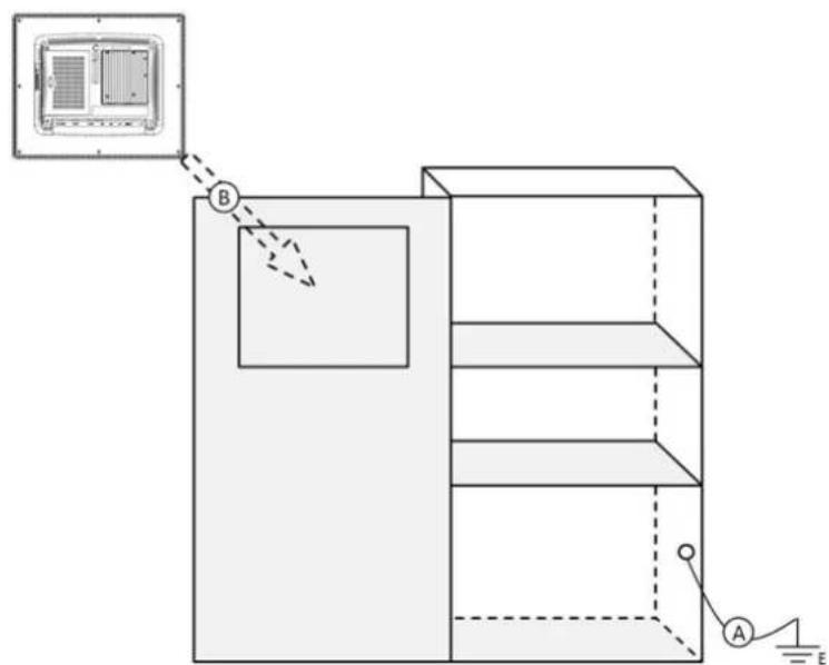
Step A: Connect the cabinet to earth ground.
Step B: Embed null TPC-xx51WP series into the cabinet without any I/O cable and power.
- System wiring
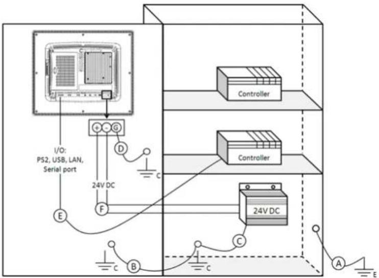
Step A: Connect the cabinet to earth ground.
Step B: Ensure that all cabinet has been grounded together.
Step C: Connect the ground of the power supply to the cabinet.
Step D: Connect the ground pin of TPC-xx51WP series to the cabinet.
Step E: Connect the I/O to the controller if needed.
Step F: Connect the V+ and V- of power supply to TPC-xx51WP series.
While completing step A to F step by step, you can supply power to TPC-xx51WP series now.
Note! Make sure all wires follow the installation guidelines or it may cause issues.

Note! If you install a USB device or Mini PCIe card on the TPC-xx51WP

series, please double check the voltage between V- and earth ground, if the voltage is not almost equal with each other, we suggest to short V- and earth ground with wiring.
2.5 Power/Digital Ground and Earth Ground
The purpose is to block all the external interference on the chassis, and prevent any possibility of bad grounding design to cause electric shock of people. This is so called level 1 isolation which consumer PC do not implement this kind of design.
■ TPC Chassis and Earth (Power pin3) are short,
■ TPC Chassis and Power / Digital GND are OPEN
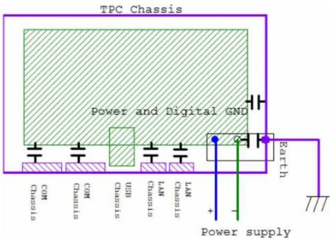
The TPC is and industrial grade product, designed to prevent external interference and the possibility of electric shock. To complete the isolation design, we need to consider the following:
The Ethernet is isolated, a LAN connection will not impact the isolation design.
For general USB devices, to solve EMI and ESD issues, they are designed as a chassis and digital short. But the TPC prevents damage to USB devices, ESD and EMI solutions are designed to use the Power GND as a vent path to ensure Power GND and Chassis GND will not have potential difference abnormalities.
For COM ports, since there are different COM port designs, long distance connection cause voltage level difference between the two COM port chassis. So the shell ground of cable must be isolated to signal digital ground
In real cases, many customers may break the level 1 isolation by 3rd party Device or cable design, in this situation, we need to consider making all the GND short (Power GND/Digital GND/Earth GND), and ensure customers have good Earth GND connection.
Chapter 3
Features in Windows Embedded
3.1 Features in Windows Embedded
TPC product supports the embedded Windows platform. This section outlines the important features (EWF, FBWF and HORM), that are provided in WES7, and UWF provided in Win EMB 8.1 Industry Pro.
3.2 Enhanced Write Filter (EWF)
Enhanced Write Filter (EWF) and File-Based Write Filter (FBWF) redirect all writes targeted at protected volumes to a RAM or disk cache, called an overlay. The overlay stores changes made to the operating system, but is removed when the device is restarted, restoring the device to its original state. Note that there is no disk-based overlay support for Windows Embedded Standard 7.
EWF works at the sector level on protected disks and allows you to commit changes so that they persist when the device is restarted. EWF is useful for thin clients that do not need to store cached information or receive frequent updates. Changes made to a system protected by EWF are stored in one or more layers that represent snapshots in time. Applying changes to an image applies all changes made to the operating system during a specific period of time.
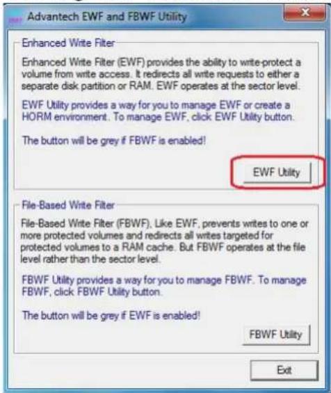
Advantech provide utility to operate EWF. Refer below steps if you want to enable.
- Click Start Menu->All Programs->Advantech->AdvWF and click EWF Utility
- Click EWF tab, and click "Enable" button
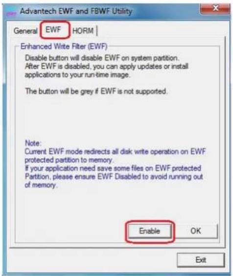
- After the system is rebooted automatically, EWF enable
3.3 File-Based Write Filter (FBWF)
File-Based Write Filter (FBWF) works at the file level instead of the sector level on protected disks. By default, FBWF protects the whole disk, but selective write through exceptions can be granted to specific files and folders. Writes to folders with write-through exceptions will be persisted when the device restarts.
Advantech provide utility to operate FBWF. Refer below steps if you want to enable
- Click Start Menu->All Programs->Advantech->AdvWF and click FBWF Utility
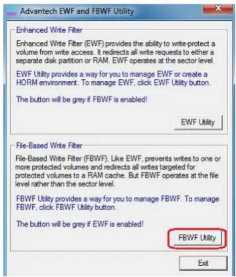
- Move volume you want to protect from "Available Volume" to "Protected Volume" and choose "Write-Through Files and Folders"
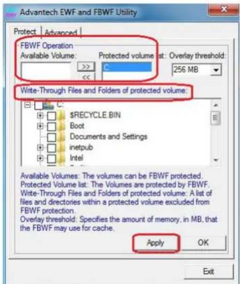
- Click "Apply", and the system is rebooted automatically. Then FBWF enable.
3.4 HORM
HORM stands for Hibernate Once Resume Many. In HORM environment, a single hibernation file is used to boot the system repeatedly. To set a HORM environment, please follow the steps below.
- Make sure EWF is disabled. You can run OSUnLock to disable EWF.
- Enable hibernation support: Open the command prompt and type "powercfg -h on"
- Run "power options" in control panel, and then select "Enable Hibernation" in hibernation pane.
Enable EWF:
- Run OSLock, and then system reboot automatically.
- Open those software that customers want to directly use after system resume from hibernation.
-
Hibernate via Advantech HORM utility:
-
Click Start Menu->All Programs->Advantech->AdvWF
-
Select "Enable Hibernation" in "Power Options".
-
Open AdvWF and enable EWF
-
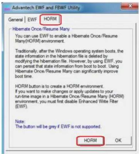
After the system is rebooted automatically, open AdvWF and click EWF Utility.
-
Click HORM tab, and click "HORM" button.
Appendix A
Serial Port Settings
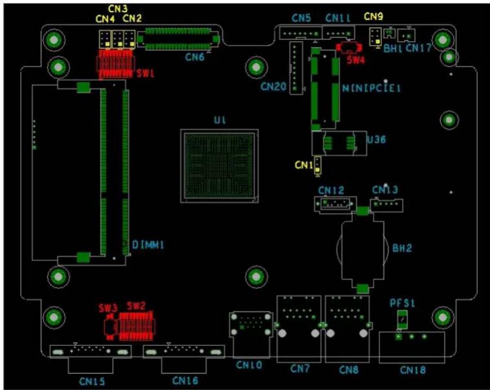
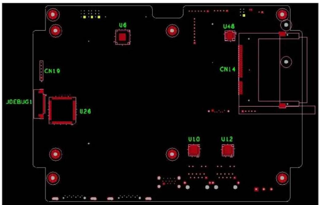
A.1 Jumper, Dip switch and Connector location
A.1.1 Top
A.1.2 Bottom
A.2 Jumper setting and Description
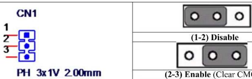
A.2.1 CMOS Clear Function (CN1)
| CMOS Clear Function | |
| Description | This jumper is used to select CMOS Clear Enable/Disable |
| Default (1-2) | |
| (2-3) Enable (Clear CMOS) | |
| (1-2) Disable | |
A.3 Switch Setting
COM2 RS232/422/485 mode setting (SW2)
| COM2 RS232/422/485 mode setting | ||
| Description This switch is used to select COM2 RS232/422/485 mode setting | ||
| Default RS232 mode | ||
| RS232 Mode | Bit 1,2,3,4,5 ONBit 6,7,8,9,10 OFF | 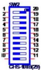 |
| RS422 Master Mode | Bit 1,2,3,4,5,10 OFFBit 6,7,8,9 ON | 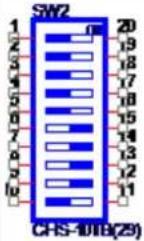 |
| RS422 Slave Mode | Bit 1,2,3,4,5 OFFBit 6,7,8,9,10 ON | 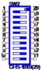 |
| RS485 Mode | Bit 1,2,3,4,5,8,9 OFFBit 6,7,10 ON | 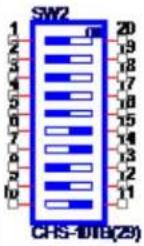 |
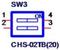
A.3.1 Termination Resistor Select (SW3)
| Termination Resistor Select | ||
| Description | This switch is used to select Termination Resistor (120 ohm) for long distance transmission or device matching. | |
| Default | Bit1 off & Bit2 off (DATA+ & RX-) | |
| DATA+ Pin 1 | Default | |
| RX- Pin 2 | ||
| R_RX+ Pin 3 | ||
| R_DATA- Pin 4 | ||
 | ||
A.4 Connector Pin Definition
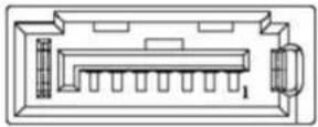
A.4.1 SATA connector (CN12)
1654004659 Serial ATA 7P 1.27mm 180D(M) DIP WATM-07DBN4A3B83.12
| Pin | Signal Description | |
| 1 | G N | D G N D |
| 2 | A+ | Signal Pair A: TX+/-(Transmit) |
| 3 | A- | |
| 4 | G N | D G N D |
| 5 | B- | Signal Pair B: RX+/ (Receive) |
| 6 | B+ | |
| 7 | G N | D G N D |
 | ||
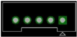
A.4.2 SATA Power connector (CN13)
1655000453 WAFER BOX 2.0mm 5P 180D(M) DIP WO/Pb JIH VEI
| Pin | Signal | Description |
| 1 +V3.3 | SATA SATA power | output 3.3V/1A |
| 2 +V5 | SATA SATA power output | 5V/1A |
| 3 +V12 | SATA SATA power output | 12V/0.5A |
| 4 | G N D | G N D |
| 5 | G N D | G N D |
 | ||
A.4.3 Mini PCIE slot (MINIPCIE)
1654002538 MINI PCI E 52P 6.8mm 90D SMD AS0B226-S68N7H
Supports PCI1.1, PCI1.2 Power Definition
| Pin Signal Description | Pin Signal Description | ||||
| 52 | +3.3Vaux / +3.3V | PCI1.1 was +3.3V, PCI1.2 was +3.3Vaux | 51 | Reserved | NC |
| 50 | GND | 49 Reserved NC | |||
| 48 | +1.5V | 47 Reserved NC | |||
| 46 | NC | NC | 45 Reserved NC | ||
| 44 | NC | NC | 43 | PIN43_MPCIE_PWRSEL | The pin to select the Pin 2, 52 power output for +3.3Vaux or +3.3V (PCI1.1 was Reserved and PIC1.2 was GND |
| 42 | NC | NC | 41 +3.3Vaux | ||
| 40 | GND | 39 +3.3Vaux | |||
| 38 | USB_D+ | USB serial data interface compliant to the USB 2.0 specification | 37 GND | ||
| 36 | USB_D- | 35 GND | |||
| 34 | GND | 33 | PETp0 | PCI Express differential transmit pair | |
| 32 | SMB_DATA | SMBus data signal compliant to the SMBus 2.0 specification | 31 PETn0 | ||
| 30 | SMB_CLK | 29 GND | |||
| 28 | +1.5V | 27 | GND | ||
| 26 | GND | 25 | PERp0 | PCI Express differential receive pair | |
| 24 | +3.3Vaux | 23 PERn0 | |||
| 22 | PERST# | Functional reset to the card | 21 | GND | |
| 20 | W_DISABLE # | Active low signal. This signal is used by the system to disable radio operation on add-in cards that implement radio frequency applications. When implemented, this signal requires a pull-up resistor on the card. | 19 Reserved NC | ||
| 18 | GND | 17 Reserved NC | |||
| Key | Key | Key | Key | ||
| 16 | NC | NC | 15 GND | ||
| 14 | NC | NC | 13 REFCLK+ | ||
| 12 | NC | NC | 11 REFCLK- | ||
| 10 | NC | NC | 9 | GND | |
| 8 | NC | NC | 7 | CLKREQ# | Reference clock request signal |
| 6 | 1.5V | 5 | NC | NC | |
| 4 | GND | 3 | NC | NC | |
| 2 | +3.3Vaux / +3.3V | PCI1.1 was +3.3V, PCI1.2 was +3.3Vaux | 1 | WAKE# | Open Drain active Low signal. This signal is used to request that the system return from a sleep/suspended state to service a function initiated wake event. |
* +3.3Vaux was suspend Power, power out to device +3.3V/1.1A
* +3.3V was core power
* +1.5V was core power, power out to device +1.5V/0.5A
A.4.4 CFast slot (CN14)
1653004849 CFast 24P 1.27mm 90D(M) SMD N7G24-A0B2RA-10-0HT-The host is connected to the CFast Card using a 7+17 pin connector
| Pin Segment CFast Name Description | ||
| S1 SATA SGND Ground for signal integrity | ||
| S2 SATA A+ | Signal Pair A : TX+/-(Transmit) | |
| S3 SATA A- | ||
| S4 SATA SGND Ground for signal integrity | ||
| S5 SATA B- | Signal Pair B : RX+/ (Receive) | |
| S6 SATA B+ | ||
| S7 SATA SGND Ground for signal integrity | ||
| Key | ||
| Key | ||
| PC1 PWR/CTL CDI NC | ||
| PC2 PWR/CTL GND GND | ||
| PC3 PWR/CTL TBD NC | ||
| PC4 PWR/CTL TBD NC | ||
| PC5 PWR/CTL TBD NC | ||
| PC6 PWR/CTL TBD NC | ||
| PC7 PWR/CTL GND GND | ||
| PC8 PWR/CTL LED1 CF_PHYRDY LED | ||
| PC9 PWR/CTL LED2 CF_HDDA LED | ||
| PC10 | PWR/CTL IO1 NC | |
| PC11 | PWR/CTL IO2 NC | |
| PC12 | PWR/CTL IO3 NC | |
| PC13 | PWR/CTL PWR | CFast Power output to Device +3.3V / 1.2A |
| PC14 | PWR/CTL PWR | |
| PC15 | PWR/CTL PGND | Ground for Power return |
| PC16 | PWR/CTL PGND | |
| PC17 | PWR/CTL CDO NC | |
A.4.5 Power in connector (CN18)
1652003104 PLUG-IN BLOCK 3P 5.08mm 90D(M) DIP ME050-50803
| Pin | Signal | Description |
| 1 Power IN V+ | 24VDC +-20% Power in | |
| 2 Power IN V- (GND) | ||
| 3 | GND_EARTH | The GND_EARTH to connect a Screw hole for short with the chassis GND |
CN18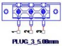 | ||
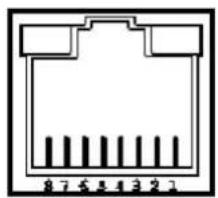
A.4.6 LAN RJ45 connector (CN7, CN8)
1652002996 PHONE JACK RJ45 14P 90D(M) DIP RTA-195AAK1A
| RJ45 Pin | Signal Description | |
| 1 | MDI0+ | In BASE-T: Media Dependent Interface[0]:1000BASE-T: In MDI configuration, MDI[0]+/- corresponds to BI_DA+/- and in MDI-X configuration MDI[0]+/- corresponds to BI_DB+/-.10BASE-T and 100BASE-TX: In MDI configuration, MDI[0]+/- is used for the transmit pair and in MDIX configuration MDI[0]+/- is used for the receive pair. |
| 2 | MDI0- | |
| 3 | MDI1+ | In BASE-T: Media Dependent Interface[1]:1000BASE-T: In MDI configuration, MDI[1]+/- corresponds to BI_DB+ and in MDI-X configuration MDI[1]+/- corresponds to BI_DA+/-.10BASE-T and 100BASE-TX: In MDI configuration, MDI[1]+/- is used for the receive pair and in MDI-X configuration MDI[1]+/- is used for the transmit pair. |
| 6 | MDI1- | |
| 4 | M | In BASE-T: Media Dependent Interface[3:2]:1000BASE-T: In MDI and in MDI-X configuration, MDI[2]+/- corresponds to BI_DC+/- and MDI[3]+/- corresponds to BI_DD+/-.100BASE-TX: Unused.10BASE-T: Unused. +D I 3 - |
| 5 | M | |
| 7 | M | |
| 8 | M | |
Left LED Right LED
| 10Link 100Link 1000 Link Active | |||
| Off | Orange | Green | Green |
natural_image
Pure electrical connector pinout diagram without any text or symbolsA.4.7 USB connector (CN10)
1654010199 USB Conn. 2.0+3.0 13P 90D(F) DIP UEA1112C-UHS6-4
| Pin | Signal | Description |
| 1, 10 | USB VBUS | USB Power output ,USB2.0 5V/0.5A and USB3.0 5V/0.9A |
| 2, 11 USB_P- USB2.0 date - | ||
| 3, 12 USB_P+ USB2.0 date + | ||
| 4,13 GND Ground for Power return | ||
| 5 SSRX- | USB3.0 RX - | |
| 6 SSRX+ | USB3.0 RX + | |
| 7 GND_DRAIN | Ground for signal return | |
| 8 SSTX- | USB3.0 TX - | |
| 9 SSTX+ | USB3.0 TX + | |
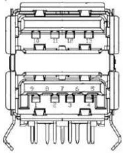 | ||
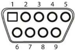
A.4.8 COM1 RS232 connector (CN15)
1654000056 D-SUB Conn. 9P 90D(M) DIP 070241MR009S200ZU
| Pin | RS232 |
| 1 | DCD |
| 2 | RX |
| 3 | TX |
| 4 | DTR |
| 5 | GND |
| 6 | DSR |
| 7 | RTS |
| 8 | CTS |
| 9 | RI |
 | |
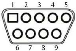
A.4.9 COM2 RS232/422/485 connector (CN16)
1654000056 D-SUB Conn. 9P 90D(M) DIP 070241MR009S200ZU
| Pin RS232 RS422 RS485 | |||
| 1 | D | C | D |
| 2 | R | X | T |
| 3 | T | X | R |
| 4 | D | T | R |
| 5 | G | N | D |
| 6 | DSR | ||
| 7 | RTS | ||
| 8 | CTS | ||
| 9 | RI | ||
 | |||
Appendix B
Driver Installation and Configuration
B.1 Intel Chipset Software Installation Utility Installation
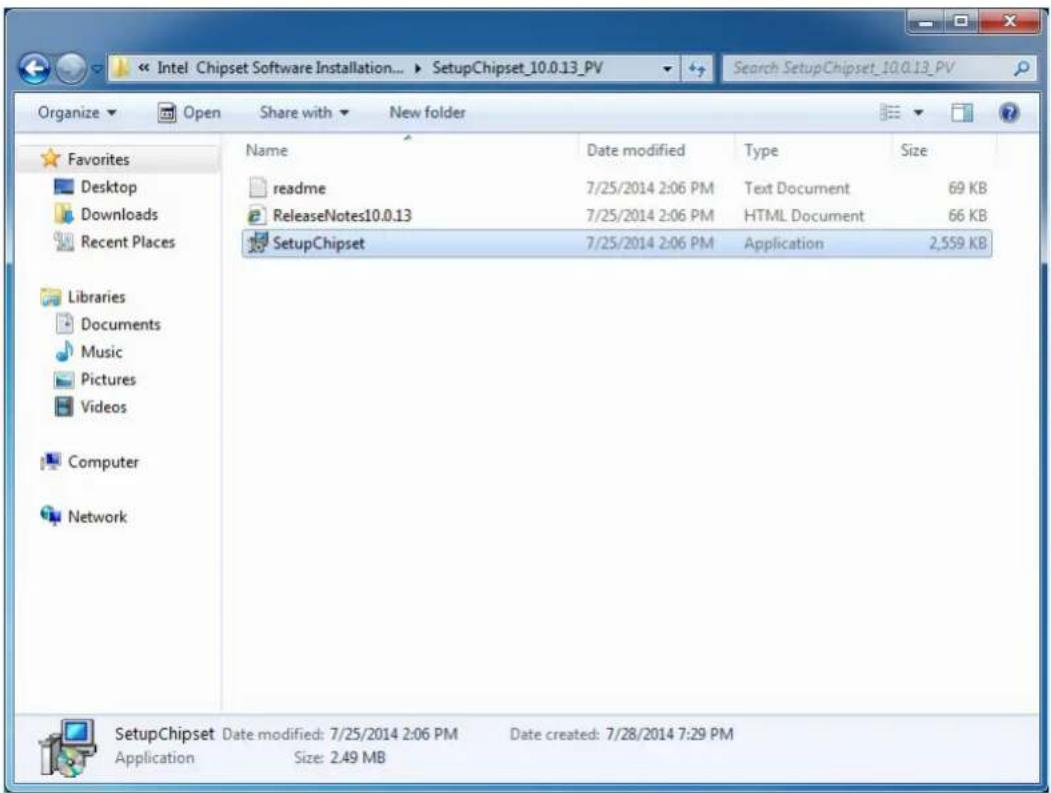
Follow the steps below to install the Intel Chipset Software Installation Utility:
- Launch
\Intel Chipset Software Installation Utility\SetupChipset_XX.X.XX_PV - Install SetupChipset.exe
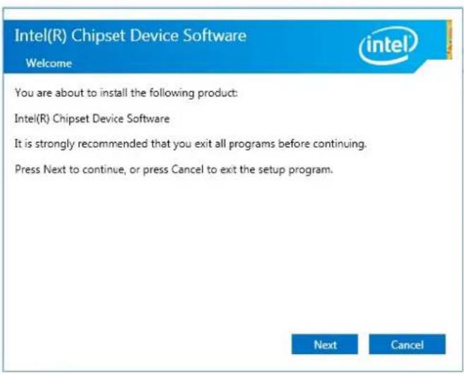
3. Click Next
4. Click Accept
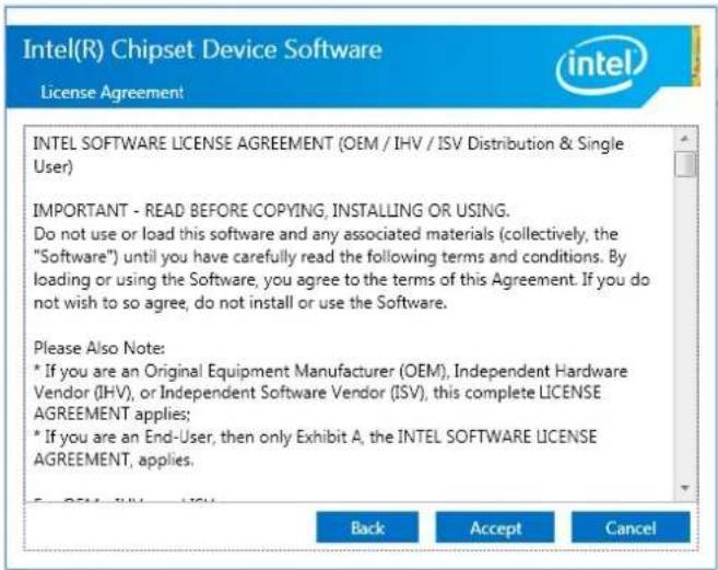
5. Click Install
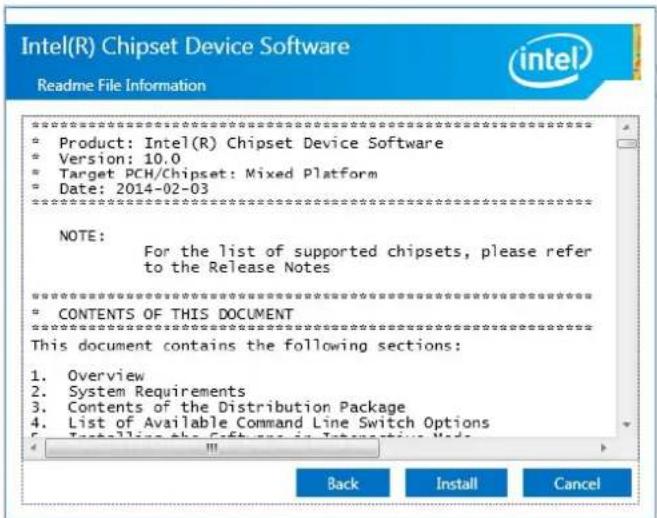
6. Click Finish
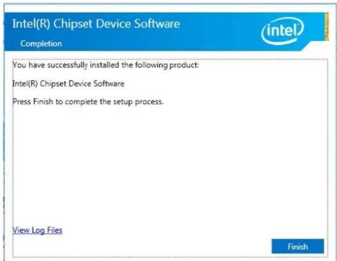
B.2 Intel Graphics Driver Installation
Follow the steps below to install the Intel Graphics driver:
- Launch folder
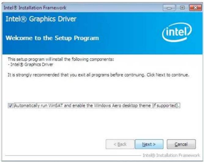
\Graphics Driver\Intel EMGD win7 XX bit\ - Install Setp.exe
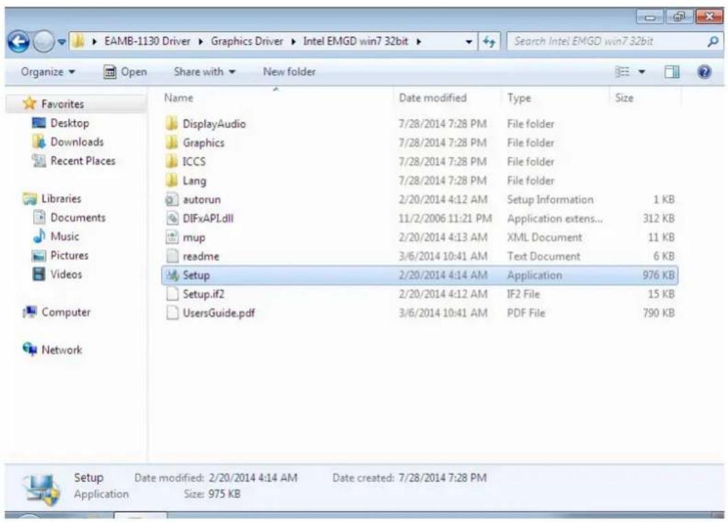
3. Click Next
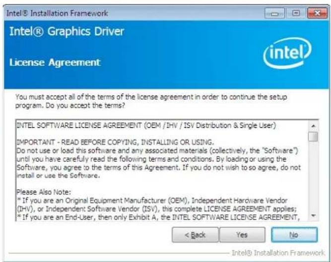
4. Click Yes
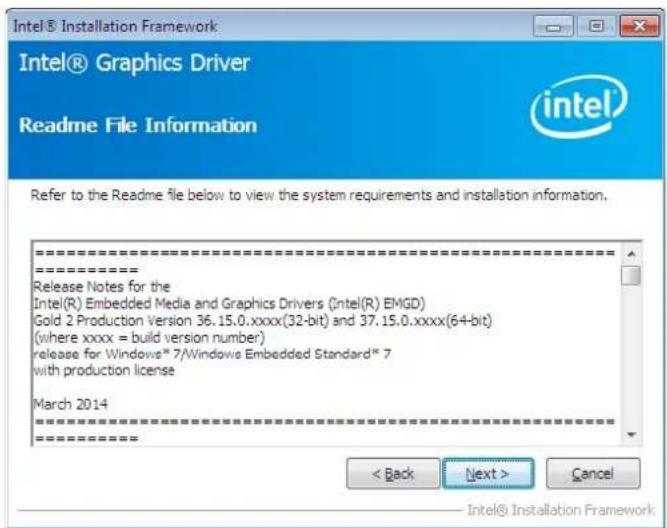
5. Click Next
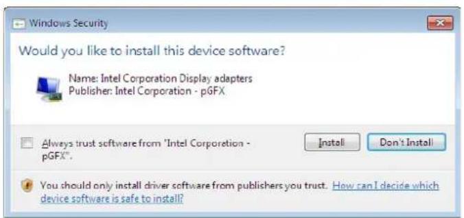
6. Click Install
7. Click Next
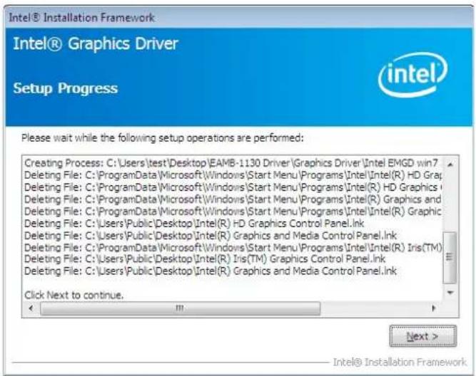
8. Choose Yes, then click Finish to restart
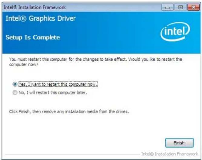
B.3 LAN Driver Installation
Follow the steps below to install the LAN driver:
- Launch folder
\LAN\Win7 \Install_Win7_XXX_XXXXXXXX - Install setup.exe
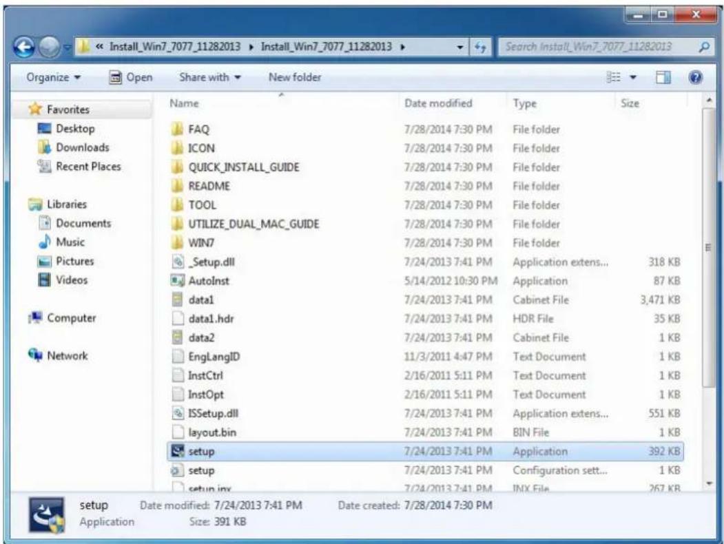
3. Click Next
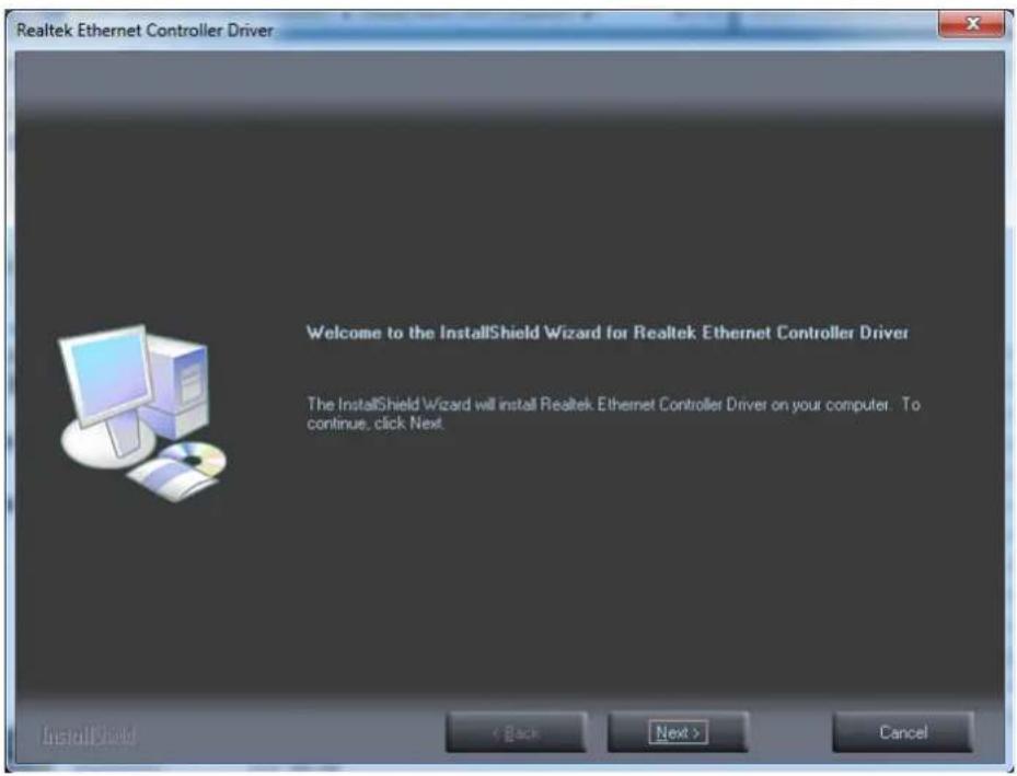
4. Click Install
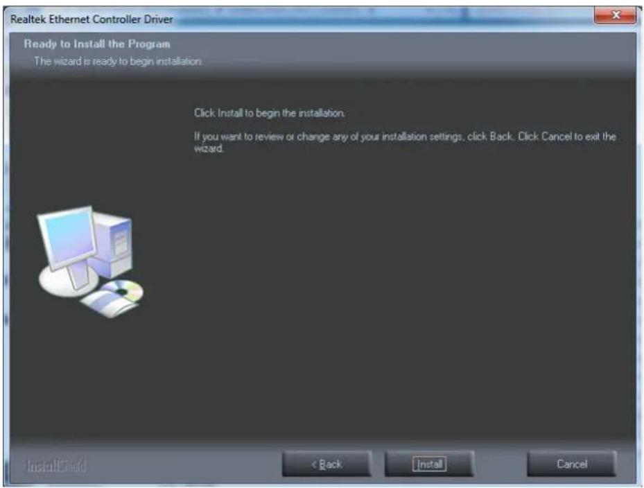
5. Click Finish
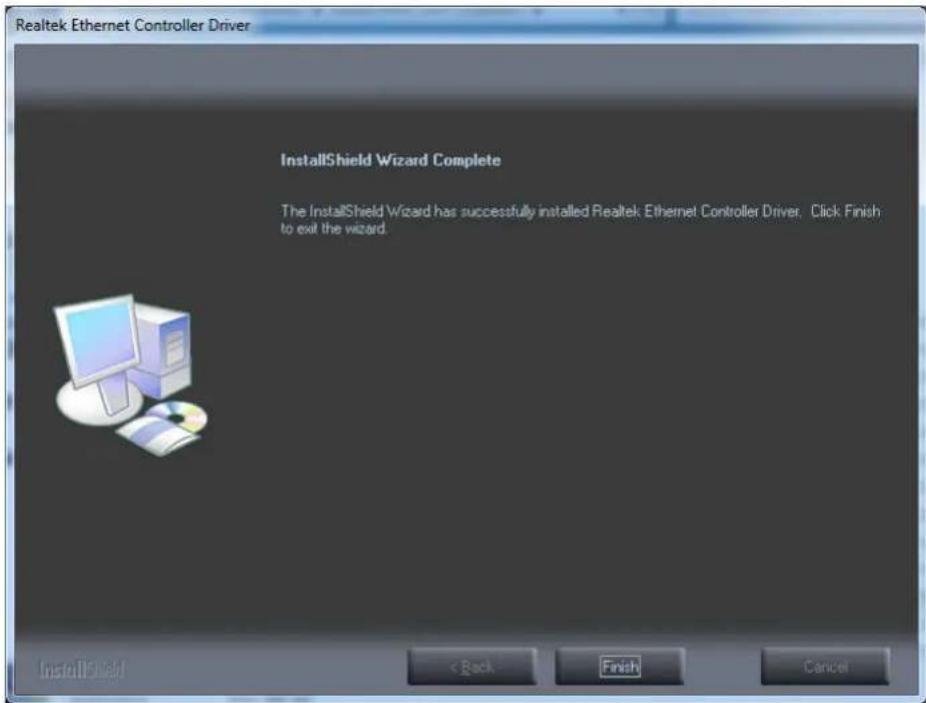
B.4 Intel® Trusted Execution Engine Driver Installation
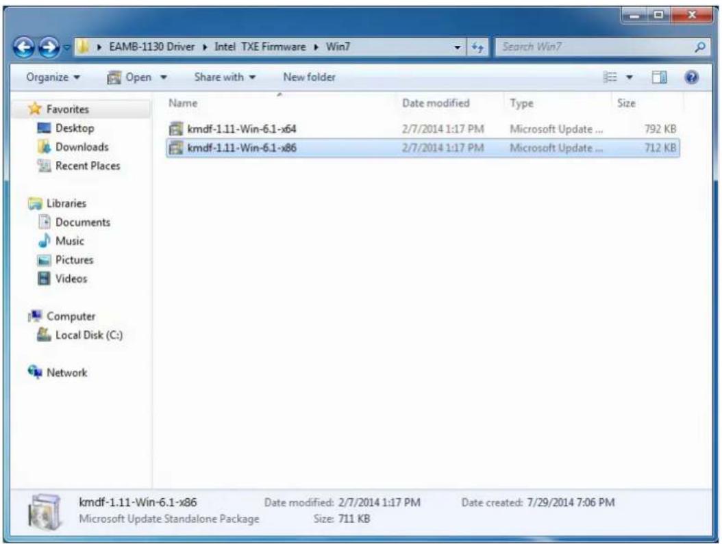
Follow the steps below to install the Intel Trusted Execution Engine driver:
- Launch folder
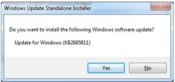
\TXE\Intel TXE Firmware\Win7 - Install kmdf-1.11-Win-6.1-x86.msu
- Click Yes
4. Click Restart Now, then the system will restart
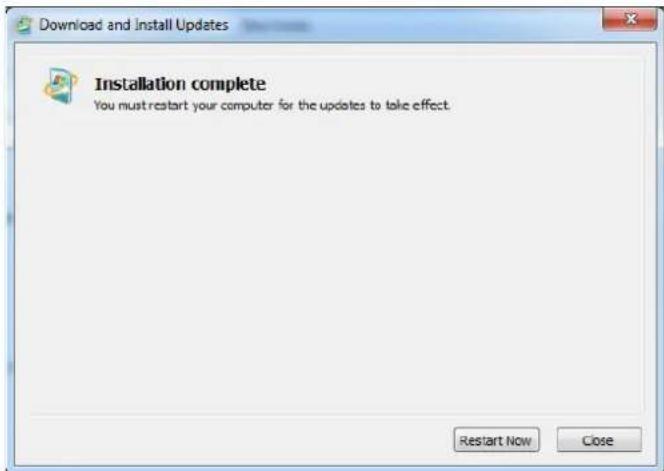
5. Launch folder \TXE\TXE\_Win7\_X\_X.X\_X.X.X.XXXX 6. Install Setup TXE.exe
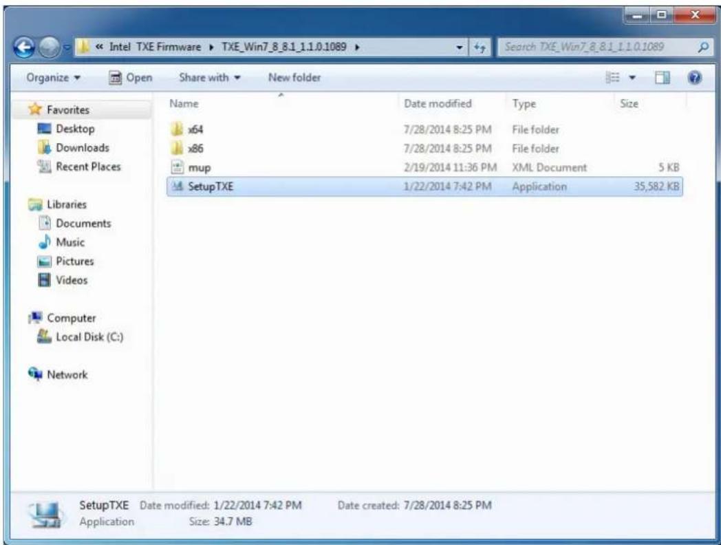
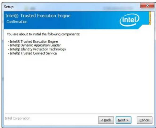
7. Click Next
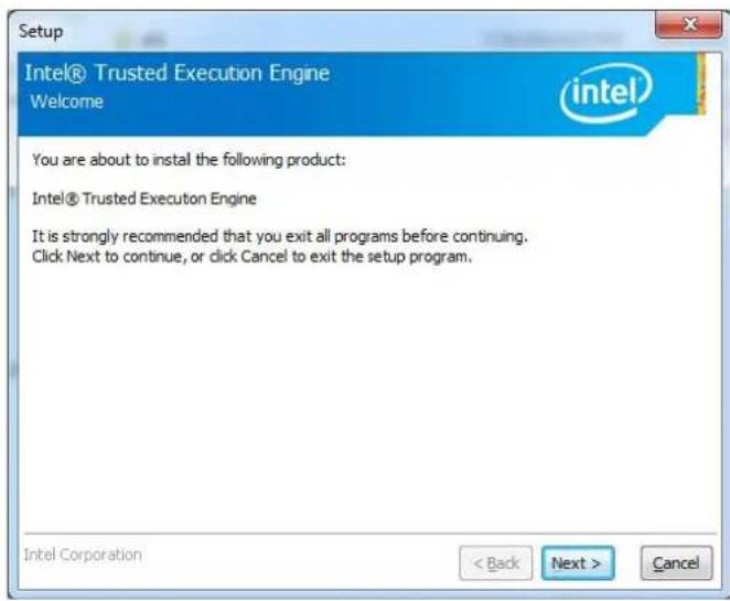
8. Click Next
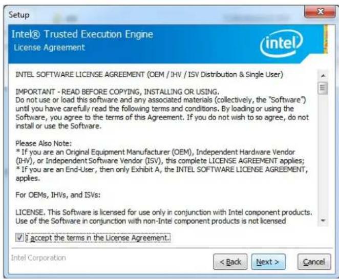
9. Click Next
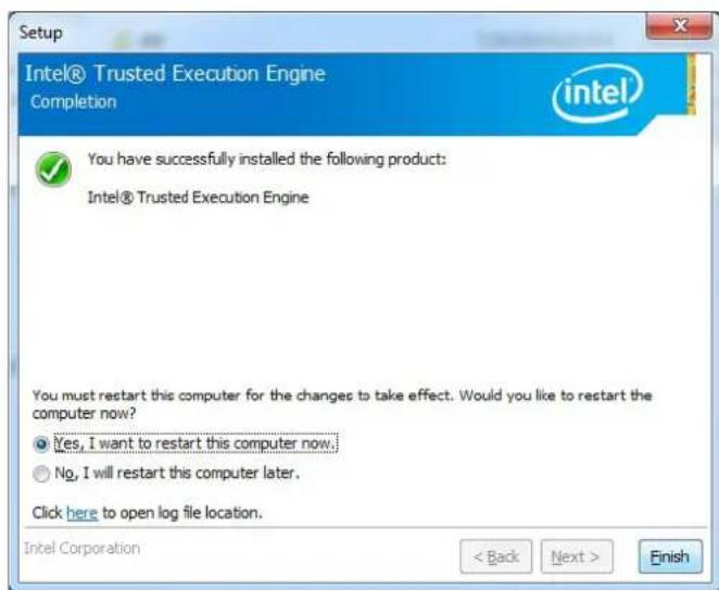
- Choose Yes, then click Finish to restart.
B.5 Windows 7 USB 3.0 Driver Installation
Follow the steps below to install the Windows 7 USB 3.0 driver:
- Launch folder
\USB3\Win7\SetupUSB3_X.X.X.XX - Install Setup.exe
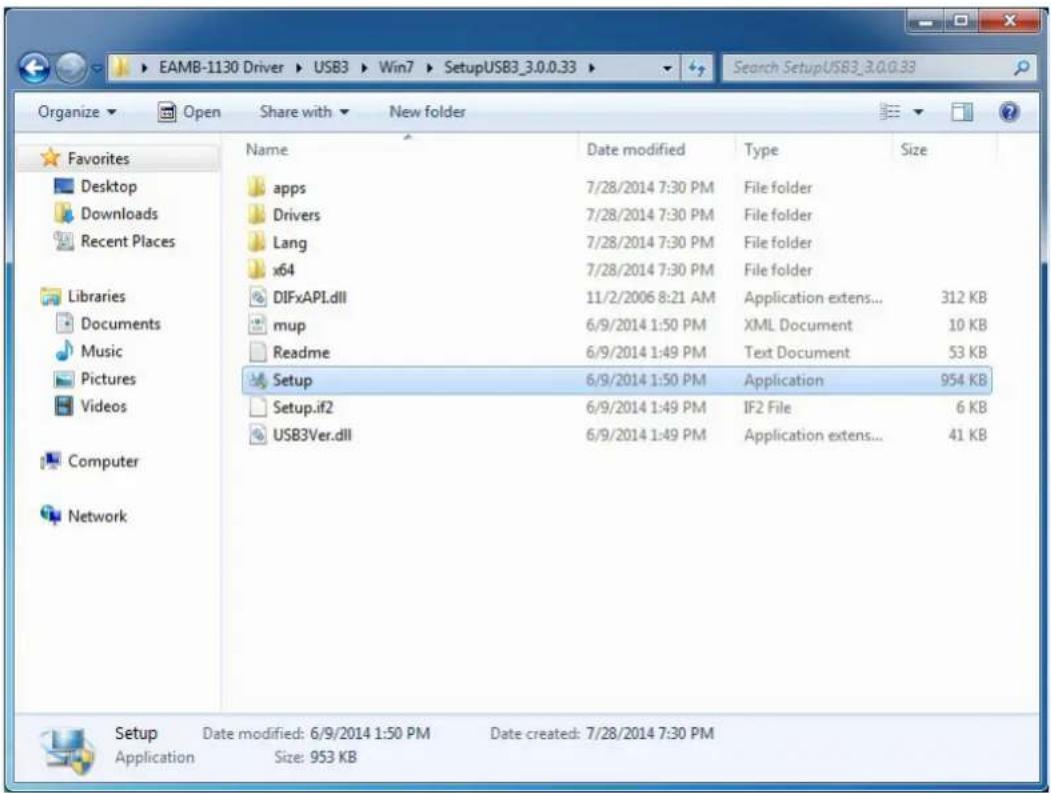
3. Click Next
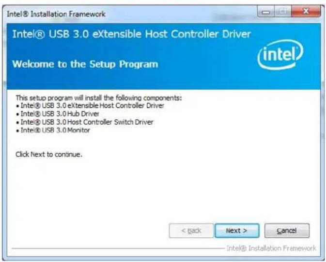
4. Click Yes
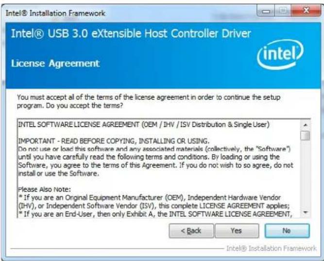
5. Click Next
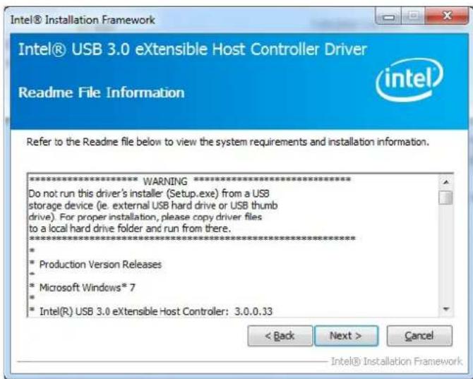
6. Click Next
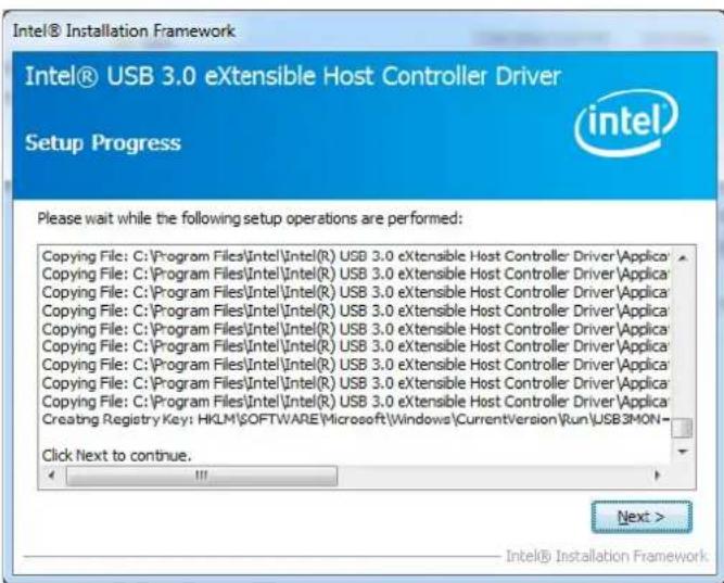
7. Choose Yes, then click Finish to restart
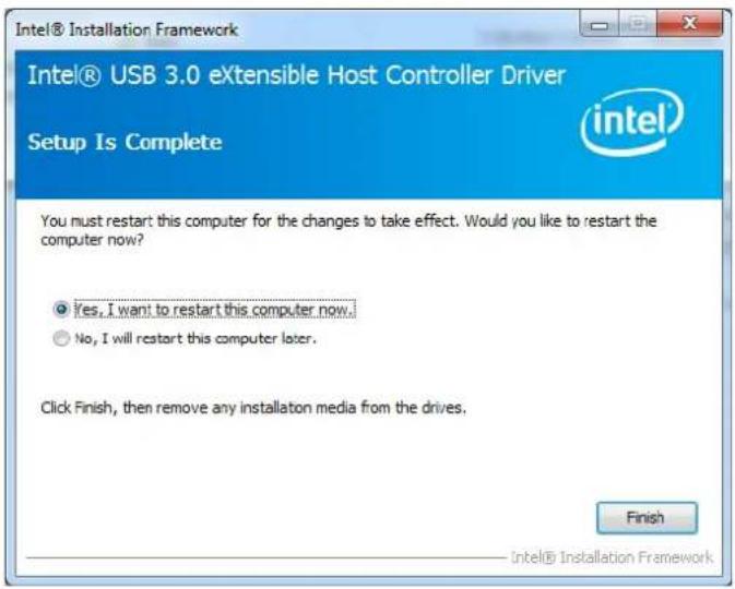
B.6 Advantech EC Driver Installation
Follow the steps below to install the EC drivers:
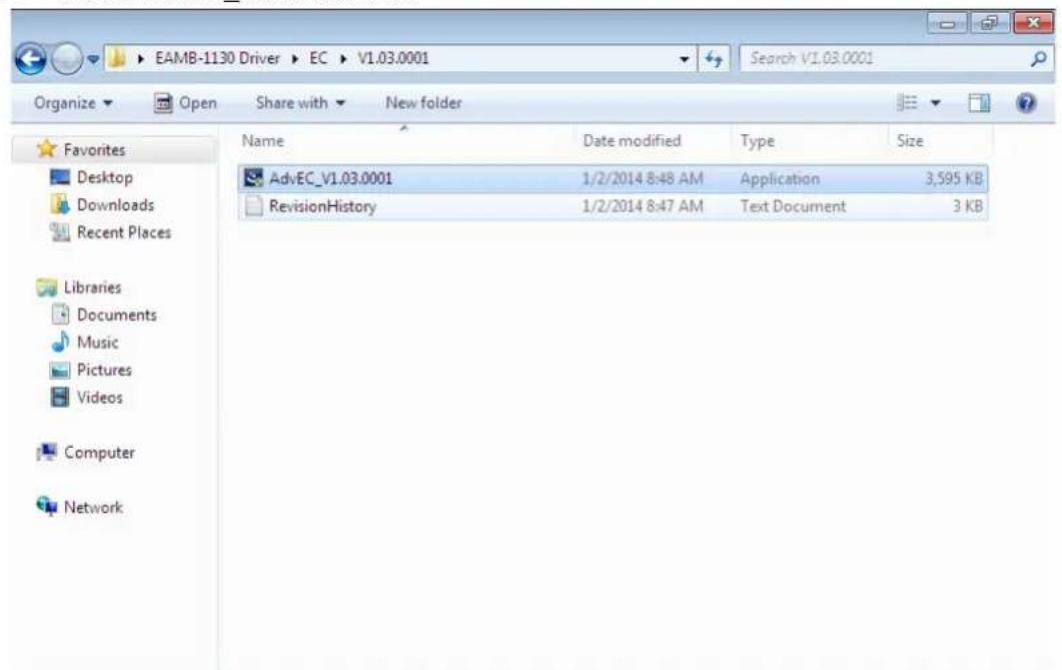
- Launch folder
\EC\Vx.xx.xxxx - Install AdvEC_Vx.xx.xxxx.exe
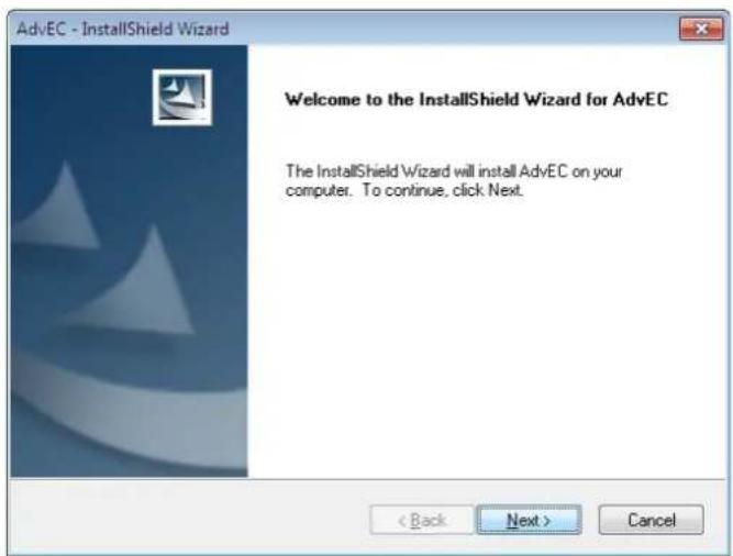
3.Click Next
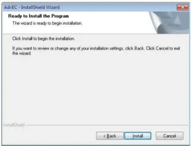
4.Click Install
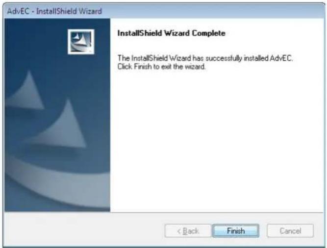
5. Click Finish
6. Choose Yes, then click OK to restart
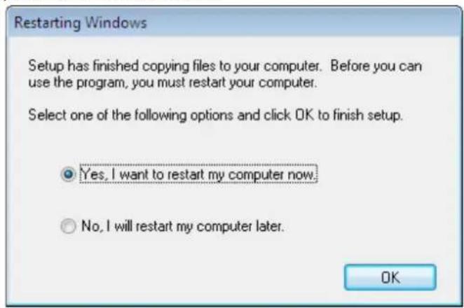
B.7 Advantech EC Brightness Control Tool Installation
Note! The Advantech EC driver must be installed first

Follow the steps below to install the EC brightness control tool:
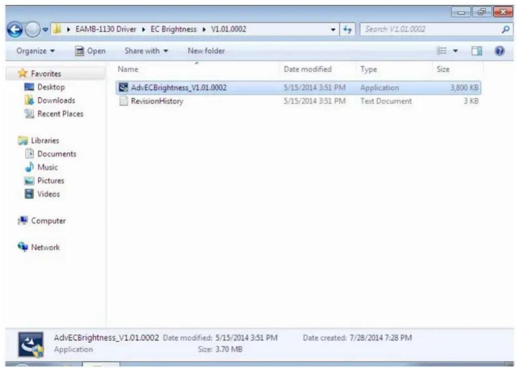
- Launch folder
\EC Brightness\Vx.xx.xxxx - Install AdvECBrightness_Vx.xx.xxxx.exe
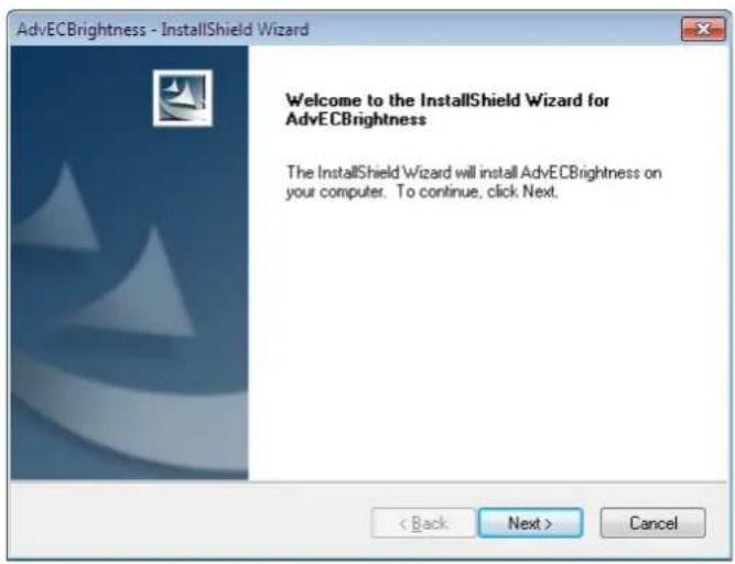
- Click Next
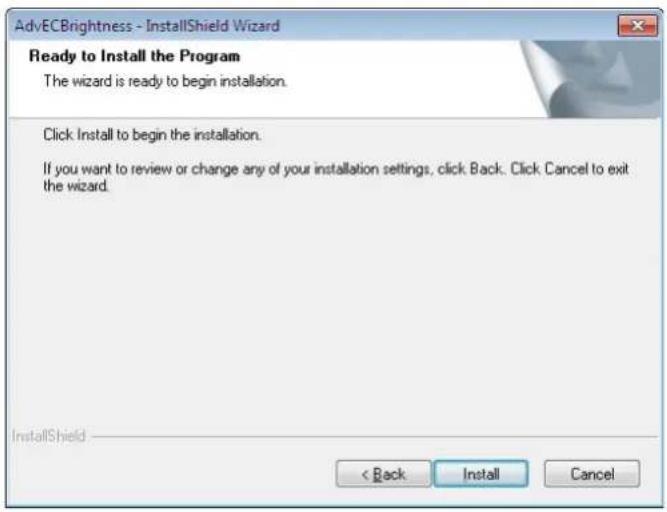
4. Click Install
5. Click Finish
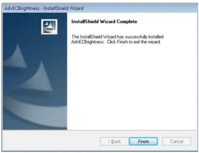
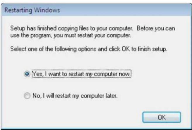
6. Choose Yes, then click OK to restart
B.8 Advantech EC Watchdog Timer Driver Installation
Note! The EC driver must be installed first

Follow the steps below to install the EC Watchdog Timer driver:
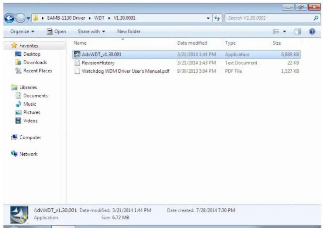
- Launch folder
\WDT\Vx.xx.xxxx - Install AdvWDT_Vx.xx.xxxx.exe
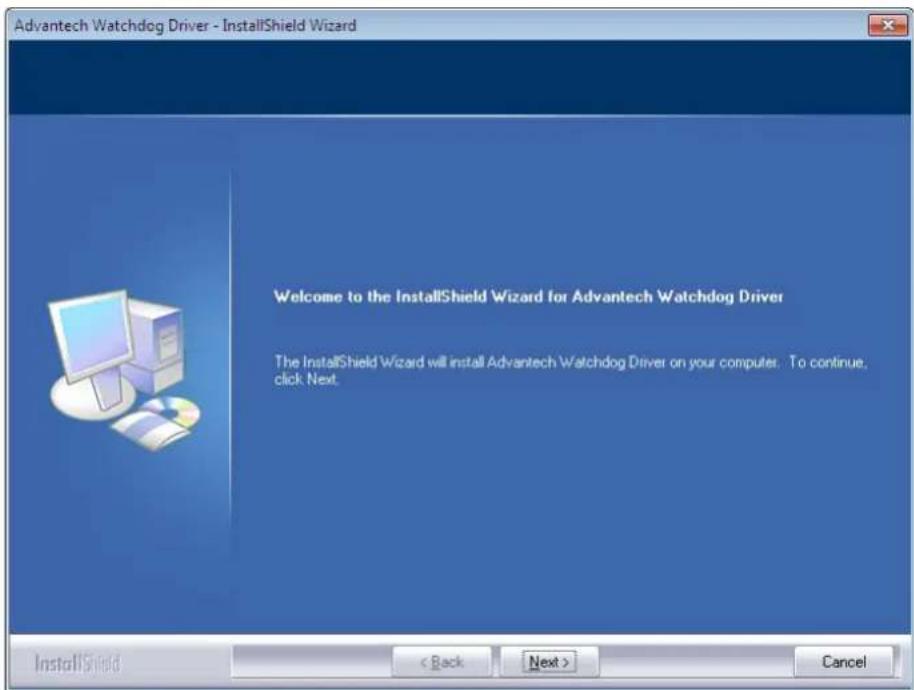
3. Click Next
4. Choose Advantech [EC]WDT, then click Next
![Advantech Watchdog Driver - InstallShield Wizard Setup Type Select the setup type that best suits your needs. Select the features you want to install, and deselect the features you do not want to install. Click Next to continue. ● Advantech [W83627] WDT ● Advantech [SCH311X] WDT ● Advantech [F75111] WDT ● Advantech [NCT6776F] WDT ● Advantech [EC] WDT InstallShield < Back Next > Cancel](/content/2026/05/818847/images/4454fdb94af00ee60c01bc5eeab1b2bdd69f4d2a4fce7f71093bf7db815451cd.jpg)
5. Click Install
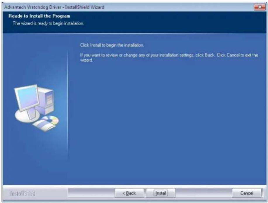
6. Click Finish
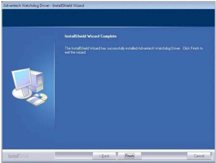
7. Choose Yes, then click OK to restart
Restarting Windows
Setup has finished copying files to your computer. Before you can use the program, you must restart your computer.
Select one of the following options and click OK to finish setup.
Yes, I want to restart my computer now.
○ No, I will restart my computer later.
OK
B.9 Advantech LMsensor Driver Installation
Follow the steps below to install the LMsensor driver:
- Launch folder
\Lmsensor\Vx.xx.xxxx - Install AdvLmsensor EC_Vx.xx.xxxx.exe
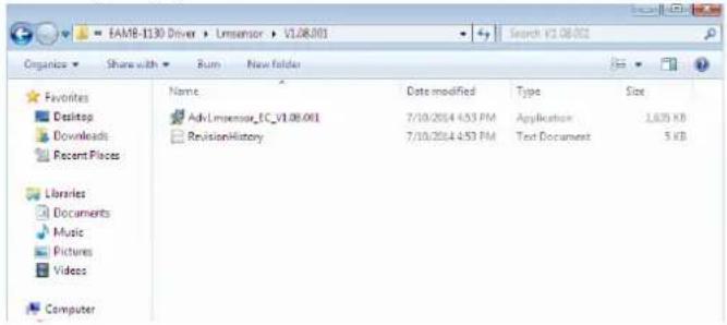
- Next
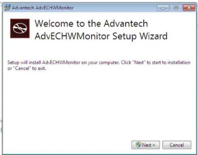
- Restart
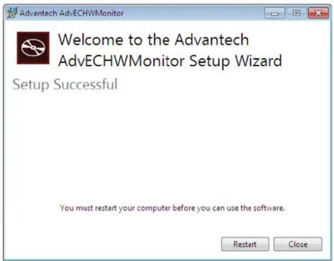
Note!
The drivers and utilities used for the panel PCs are subject to change without notice. If in doubt, check Advantech's website or contact our application engineers for the latest information regarding drivers and utilities.

Appendix C
BIOS Setup
AMI BIOS has been integrated into many motherboards for over a decade. With the AMI BIOS Setup program, users can modify BIOS settings and control various system features. This chapter describes the basic navigation of the BIOS Setup Utility
![MOS Setup Utility - Copyright (C) 2014 American Megatrends, Inc. Main Advanced Chipset Security Boot Save & Exit BIOS Information BIOS Vendor American Megatrends Core Version 5.0.1.0 0.18 x64 Compliance UEFI 2.4; PI 1.3 Project Version TPC 1130000IF50X013 Build Date and Time 12/03/2014 19:07:13 Memory Information Total Memory 8192 MB (DDR3L) System Language [English] System Date [Med 12/10/2014] System Time [01:07:47] Access Level Administrator Choose the system default language +: Select Screen +/-: Select Item Enter: Select +/-: Change Opt. F1: General Help F2: Previous Values F3: Optimized Defaults F4: Save & Exit ESC: Exit Version 8.17.124G. Copyright (C) 2014 American Megatrends, Inc.](/content/2026/05/818847/images/49f88e60b805c154fd4193dd4e6b14d6542660ceea1c13acee9fc7ac22ce3816.jpg)
AMI's BIOS ROM has a built-in Setup program that allows users to modify the basic system configuration. This information is stored in flash ROM so it retains the Setup information when the power is turned off.
C.1 Entering Setup
Turn on the computer and check for the patch code. If there is a number assigned to the patch code, it means that the BIOS supports your CPU. If there is no number assigned to the patch code, please contact an Advantech application engineer to obtain an up-to-date patch code file. This will ensure that your CPU's system status is valid. After ensuring that you have a number assigned to the patch code, press and you will immediately be allowed to enter Setup.
C.1.1 Main Setup
When you first enter the BIOS Setup Utility, users will enter the Main setup screen. Users can always return to the Main setup screen by selecting the Main tab. There are two Main Setup options. They are described in this section. The Main BIOS Setup screen is shown below.
![Aptio Setup Utility - Copyright (C) 2014 American Megatrends, Inc. Main Advanced Chipset Security Boot Save & Exit BIOS Information BIOS Vendor Core Version Compliance Project Version Build Date and Time Memory Information Total Memory System Language System Date System Time Access Level American Megatrends 5.0.1.0 0.18 x64 UEFI 2.4; PI 1.3 TPC 1130000IF60X013 12/09/2014 19:07:13 8152 MB (DDR3L) [English] [Wed 12/10/2014] [01:07:47] Administrator Choose the system default language ++: Select Screen I↓: Select Item Enter: Select +/-: Change Opt. F1: General Help F2: Previous Values F3: Optimized Defaults F4: Save & Exit ESC: Exit Version 2.17.1246. Copyright (C) 2014 American Megatrends, Inc.](/content/2026/05/818847/images/02df2b321d6d17c96a36035aef470e873254dc61a6ec7cc726b2ae5fd11cb86e.jpg)
The Main BIOS setup screen has two main frames. The left frame displays all the options that can be configured. Grayed-out options cannot be configured; options in blue can. The right frame displays the key legend.
Above the key legend is an area reserved for a text message. When an option is selected in the left frame, it is highlighted in white. Often a text message will accompany it.
■ System time / System date
Use this option to change the system time and date. Highlight System Time or System Date using the
Note! Before installing WinCE image, IDE configuration must set SATA Mode to IDE Mode in BIOS to boot successfully.

C.1.2 Advanced BIOS Features Setup
Select the Advanced tab from the setup screen to enter the Advanced BIOS Setup screen. Users can select any item in the left frame of the screen, such as CPU Configuration, to go to the sub menu for that item. Users can display an Advanced BIOS Setup option by highlighting it using the
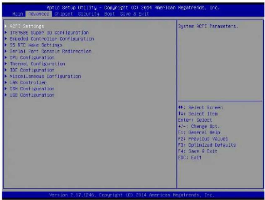
C.1.2.1 ACPI Settings Configuration
![Aptio Setup Utility - Copyright (C) 2014 American Megatrends, Inc. advanced ACPI Settings Enable ACPI Auto Configuration [Disabled] Enable Hibernation [Enabled] ACPI Sleep State [SB (Suspend to RAM)] Lock Legacy Resources [Disabled] Enables or Disables BIOS ACPI Auto Configuration. ++: Select Screen ↓: Select Item Enter: Select +/-: Change Opt. F1: General Help F2: Previous Values F3: Optimized Defaults F4: Save & Exit ESC: Exit Version 8.17.1246. Copyright (C) 2014 American Megatrends, Inc.](/content/2026/05/818847/images/8418d46ab19ce8685cd247b6e5c1e0f430d4c5b16eeb355b580d803a8827d7c9.jpg)
■ Enable ACPI Auto Configuration
This item allows users to enable or disable BIOS ACPI auto configuration.
■ Enable Hibernation
This item allows users to enable or disable System ability to hibernate (OS/S4 sleep State). This option may be not effective with some OS.
ACPI Sleep State
This item allows users to select the ACPI sleep state. The system will enter when the SUSPEND button is pressed.
■ Lock Legacy Resources
Enables or Disables Lock of Legacy Resources
C.1.2.2 Super I/O Configuration
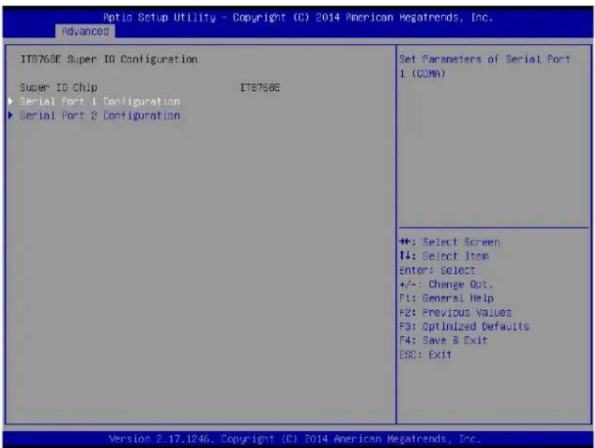
Serial Port 1 Configuration
Set Parameters of Serial Port 1 (COMA)
Serial Port 2 Configuration
Set Parameters of Serial Port 2 (COMB)
C.1.2.3 Embedded Controller Configuration
![Aptio Setup Utility - Copyright (C) 2014 American Megatrends, Inc. Advanced EC Firmware Version I2B3BX0005 EC Hardware Monitor CPU temperature : +32°C +VBAT : +2.872 V +5VSB : +5.020 V Vin : +24.195 V Vcore : +0.868 V Current : +0.314 A iManager HatchDog IRQ [Disable] EC Hatch Dog Function [Disable] Select Trg Number eBrain HatchDog ++: Select Screen T#: Select Item Enter: Select +/-: Change Opt. F1: General Help F2: Previous Values F3: Optimized Defaults. F4: Save & Exit ESC: Exit Version 2.17.1246. Copyright (C) 2014 American Megatrends, Inc.](/content/2026/05/818847/images/01797686920cbb8bdc3e2a0ba8f0089076c25a92d36e6f87d51e6700cfad10d1.jpg)
EC Hardware Monitor
This page displays all information about system Temperature/Voltage/Current.
■ iManager WatchDog IRQ
This item allows users to set the IRQ number of EC watchdog.
■ EC Watch Dog Function
This item allows users to select EC watchdog timer.
C.1.2.4 S5 RTC Wake Settings
![Aptio Setup Utility - Copyright (C) 2014 American Megatrends, Inc. advanced Wake system from 85 [Disabled] Enable or disable System wake on alarm event. Select FixedTime, system will wake on the hrs::min::sec specified. Select DynamicTime . System will wake on the current time + Increase minute(s) +: Select Screen +: Select Item Enter: Select +/-: Change Opt. F1: General Help F2: Previous Values F3: Optimized Defaults F4: Save & Exit E&C: Exit Version 8.17.1246. Copyright (C) 2014 American Megatrends, Inc.](/content/2026/05/818847/images/3f566404610722ff61c1004a32ad1fa713151f8fe29ea58f2388b0fb6dd14c30.jpg)
■ Wake system with Fixed Time
Enable or disable System wake on alarm event. Select FixedTime, system will wake on the hr::min::sec specified.
C.1.2.5 Serial Port Console Redirection
![Aptio Setup Utility - Copyright (C) 2014 American Megatrends, Inc. Advanced COMO Console Redirection [Disabled] ▶ Console Redirection Settings COM1 Console Redirection [Disabled] ▶ Console Redirection Settings Legacy Console Redirection ▶ Legacy Console Redirection Settings Serial Port for Out-of-Band Management/ Windows Emergency Management Services (EMS) Console Redirection [Disabled] ▶ Console Redirection Settings Console Redirection Settings Console Redirection Enable or Disable. ++: Select Screen T4: Select Item Enter: Select +/-: Change Opt. F1: General Help F2: Previous Values F3: Optimized Defaults F4: Save & Exit ESC: Exit Version 2.17.1246. Copyright (C) 2014 American Megatrends, Inc.](/content/2026/05/818847/images/a3957941e91f4c3fa8d7d6ff6445207ec2feb9a6036ec1647ab1664697a70514.jpg)
■ Console Redirection
This item allows users to enable or disable console redirection for Microsoft Windows Emergency Management Services (EMS).
■ Console Redirection
This item allows users to configuration console redirection detail settings.
C.1.2.6 CPU Configuration
![Aptic Setup Utility - Copyright (C) 2014 American Megatrends, Inc. Advanced CPU Configuration Socket 0 CPU Information CPU Speed 1751 MHz 64-bit Supported Execute Disable Bit [Enabled] Intel Virtualization Technology [Enabled] Socket specific CPU Information ++: Select Screen ↑↓: Select Item Enter: Select +/-: Change Opt. F1: General Help F2: Previous Values F3: Optimized Defaults F4: Save & Exit E8G: Exit Version 2.17.1246. Copyright (C) 2014 American Megatrends, Inc.](/content/2026/05/818847/images/d3dad471504f1d8e09c735fbfbe2e097711456225373f802d747269a88a34512.jpg)
■ Execute Disable Bit
This item allows users to enable or disable Execute Disable Bit.
XD can prevent certain classes of malicious buffer overflow attacks when combined with a supporting OS (Windows server 2003 SP1, Windows XP SP2, RedHat Enterprise 3 update 3.)
Intel Virtualization Technology
This item allows users to enable or disable Intel Virtualization Technology.
When enabled, a VMM can utilize the additional hardware capabilities provided by Vanderpool Technology.
C.1.2.7 Thermal Configuration
![Optic Setup Utility - Copyright (C) 2014 American Megatrends, Inc. Advanced Thermal Configuration Parameters Critical Trip Point [90 C] Passive Trip Point [85 C] This value controls the temperature of the ACPI critical Trip Point in which the OS will shut the system off. +: Select Screen +: Select Item Enter: Select +/-: Change Opt. F1: General Help F2: Previous Values F3: Optimized Defaults F4: Save & Exit ESC: Exit Version 2.17.1246. Copyright (C) 2014 American Megatrends, Inc.](/content/2026/05/818847/images/c1c781303768bff8cf2c2759ccb017f43f2146e2af0116c487aae582eb3a9fda.jpg)
Critical Trip Point
This value controls the temperature of the ACPI critical Trip Point in which the OS will shut the system off.
■ Passive Trip Point
This value controls the temperature of the ACPI critical Trip Point - the point in which OS will begin throttling the processor.
C.1.2.8 IDE Configuration
![Aptio Setup Utility - Copyright (C) 2014 American Megatrends, Inc. Advanced IDE Configuration Serial-ATR (SATa) SATA Test Mode SATA Speed Support SATA DDD Port SATA Mode Serial-ATR Port 0 SATA Port0 HotPlug Serial-ATR Port 1 SATA Port1 HotPlug SATA Port0 Not Present SATA Port1 Not Present [Enabled] [Disabled] [Gen2] [No ODC] [AHCI Model] [Enabled] [Disabled] [Enabled] [Disabled] Enable / Disable Serial ATA ++: Select Screen ↑↓: Select Item Enter: Select +/-: Change Opt. F1: General Help F2: Previous Values F3: Optimized Defaults F4: Save & Exit E8C: Exit Version 2.17.1246. Copyright (C) 2014 American Megatrends, Inc.](/content/2026/05/818847/images/3c10a0dae393a7aaf738d6942c78cf61e062a2865f58680355e7b7fae410812f.jpg)
Serial-ATA (SATA)
This item allows users to enable or disable SATA devices.
■ SATA Test Mode
Test Mode enable / disable..
■ SATA Speed Support
Indicates the maximum speed the SATA controller can support.
SATA ODD Port
SATA ODD is Port0 or Port1.
SATA Mode
This item allows users to select SATA mode selection. (Determines how SATA controller(s) operate)
Serial-ATA Port 0 / Port1
Enable / Disable Serial ATA Port0 / Port1.
■ SATA Port 0 / Port1 HotPlug
Enable / Disable SATA Port0 / Port1 hotplug function.
Note! Before installing WinCE image, IDE configuration must set SATA Mode to IDE Mode in BIOS to boot successfully.

C.1.2.9 Miscellaneous Configuration
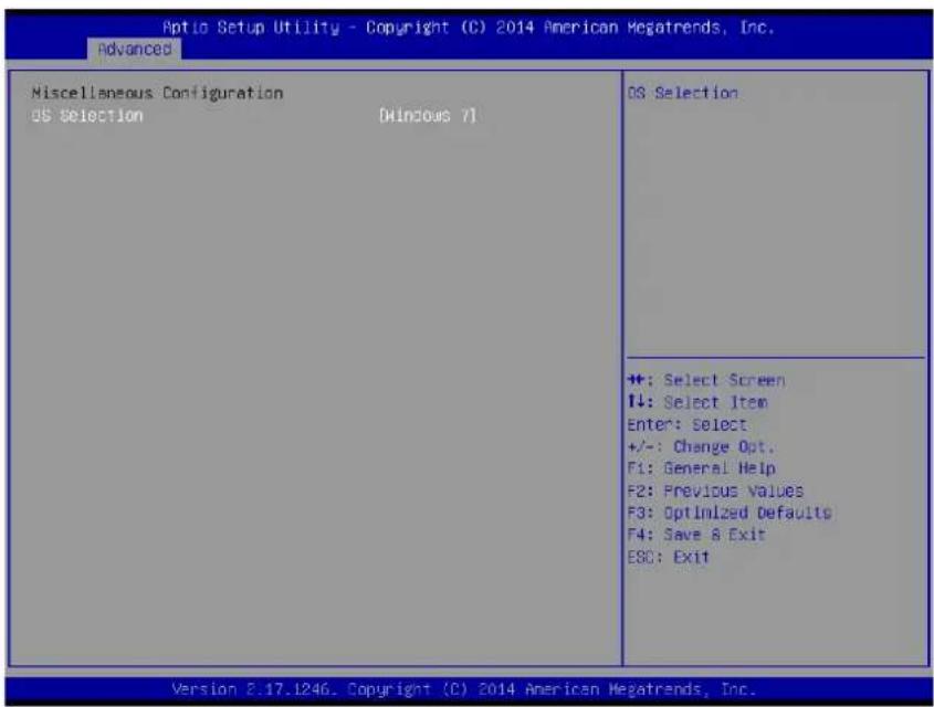
OS Selection
OS Selection to choose Windows 8.X / Windows 7
C.1.2.10 LAN Controller
![Aptio Setup Utility - Copyright (C) 2015 American Megatrends, Inc. Advanced LAN Configuration LAN A Controller [Enabled] LAN B Controller [Enabled] Make on LAN Enable [Enabled] Enable or disable LAN A. ++: Select Screen T↓: Select Item Enter: Select +/-: Change Opt. F1: General Help F2: Previous Values F3: Optimized Defaults F4: Save & Exit ESC: Exit Version 2.17.1246. Copyright (C) 2015 American Megatrends, Inc.](/content/2026/05/818847/images/bf7a1c6749437157bdfb91665a02769adc8ab83853327c26ea303345c6283037.jpg)
■ LAN A Controller
Enable or disable onboard NIC.
■ LAN B Controller
Enable or disable onboard NIC.
■ Wake on LAN Enable
Enable/Disable integrated LAN to wake the system
C.1.2.11 CSM Configuration
![Optic Setup Utility - Copyright (C) 2014 American Megatrends, Inc. Advanced Compatibility Support Module Configuration CSM Support [Enabled] CSM16 Module Version 07.75 GateA20 Active [Upon Request] Option ROM Messages [Force BIOS] Boot option filter [UEFI only] Option ROM execution Network [UEFI] Storage [UEFI] Video [Legacy] Other PCI devices [UEFI] Enable/Disable CSM Support. ##: Select Screen #1: Select Item Enter: Select +/-: Change Opt. F1: General Help F2: Previous Values F3: Optimized Defaults F4: Save & Exit ESG: Exit Version 2.17.1246. Copyright (C) 2014 American Megatrends, Inc.](/content/2026/05/818847/images/c80ab6e97d371e98f5d69fd0449f078a663bd1ad8f7302e2ca57266a472819a5.jpg)
CSM Support
Enable/Disable CSM Support.
GateA20 Active
UPON REQUEST - GA20 can be disabled using BIOS services. ALWAYS - do not allow disabling GA20; this option is useful when any RT code is executed above 1 MB.
Option ROM Messages
Set display mode for Option ROM
■ Boot option filter
This option controls Legacy/UEFI ROMs priority
Network
Controls the execution of UEFI and Legacy PXE OpROM
Storage
Controls the execution of UEFI and Legacy Storage OpROM
Video
Controls the execution of UEFI and Legacy Video OpROM
■ Other PCI devices
Determines OpROM execution policy for devices other than Network, Storage, or Video
C.1.2.12USB Configuration
![Aptio Setup Utility - Copyright (C) 2014 American Megatrends, Inc. advanced USB Configuration USB Module Version 8.11.02 USB Devices: 1 Drive, 1 Keyboard, 2 Mice, 2 Hubs Legacy USB Support [Enabled] XHCI Hand-off [Enabled] EHCI Hand-off [Disabled] USB Mass Storage Driver Support [Enabled] USB hardware delays and time-outs: USB transfer time-out [20 sec] Device reset time-out [20 sec] Device power-up delay [Auto] Mass Storage Devices: USB.2.0 Flash Disk 2.10 [Auto] Enables Legacy USB support. AUTO option disables legacy support if no USB devices are connected. DISABLE option will keep USB devices available only for EFI applications. ++: Select Screen ↓: Select Item Enter: Select +/-: Change Opt. F1: General Help F2: Previous Values F3: Optimized Defaults F4: Save & Exit ESC: Exit Version 2.17.1246. Copyright (C) 2014 American Megatrends, Inc.](/content/2026/05/818847/images/f3328ae899a71c6a4565e5fd0aa312445d92940e732fb9b319b64407a886e48c.jpg)
■ Legacy USB Support
Enables support for legacy USB. Auto option disables legacy support if no USB devices are connected. DISABLE option will keep USB devices available only
XHCI Hand-Off
This is a workaround for OSes without XHCI hand-off support. The XHCI ownership change should claim by XHCI driver.
EHCI Hand-Off
This is a workaround for OSes without EHCl hand-off support. The EHCl ownership change should claim by EHCl driver.
USB Mass Storage Driver Support
This item allows you to enable or disable the USB mass storage device support.
■ Device reset time-out
USB mass storage device start unit command time-out.
■ Device power-up delay
Maximum time the device will take before it properly report itself to the host controller. "Auto" uses default value: for a Root port it is 100 ms, for a Hub port the delay is taken from Hub descriptor.
C.1.3 Chipset Configuration
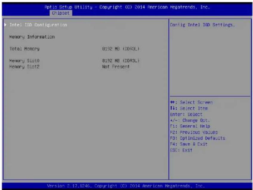
Intel IGD Configuration
Configure Intel IGD Settings
C.1.3.1 Intel IGD Configuration
![Aptio Setup Utility - Copyright (C) 2014 American Megatrends, Inc. Chipset GDP Configuration GDP Driver [Disabled] Intel ISO Configuration Integrated Graphics Device [Enabled] ISO Turbo Enable [Enabled] Primary Display [ISO] Enable GOP Driver will unload VBIOS: Disable it will load VBIOS ++: Select Screen I4: Select Item Enter: Select +/-: Change Opt. F1: General Help F2: Previous Values F3: Optimized Defaults F4: Save & Exit ESC: Exit Version 2.17.1246. Copyright (C) 2014 American Megatrends, Inc.](/content/2026/05/818847/images/79e749b12166abeff63f2ddcda683da04f7ff8cb9552e475b0504faf9f63e773.jpg)
GOP Driver
Enable GOP Driver will unload VBIOS; Disable it will load VBIOS.
C.1.4 Security
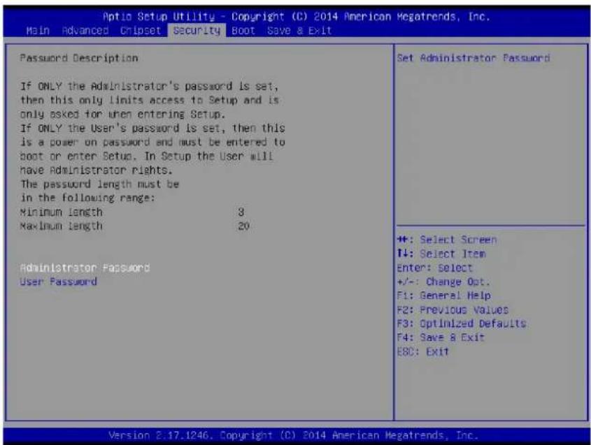
Select Security Setup from the main BIOS setup menu. All Security
Setup options, such as password protection and virus protection are described in this section. To access the sub menu for the following items, select the item and press
Administrator Password
Set Administrator Password..
User Password
Set User Password..
C.1.5 Boot
![Optio Setup Utility - Copyright (C) 2014 American Megatrends, Inc. Main Advanced Chipset Security Boot Save & Exit Boot Configuration Setup Prompt Timeout Bootup NumLock State Quiet Boot Fast Boot Boot Option Priorities Boot Option #1 Boot Option #2 L [On] [Disabled] [Disabled] [UEFI: USB.2.0 Flash...] [UEFI: Built-in EFI ...] Number of seconds to wait for setup activation key. ES535(0+FFFF) means indefinite waiting. ++: Select Screen ↑↓: Select Item Enter: Select +/-: Change Opt. F1: General Help F2: Previous Values F3: Optimized Defaults F4: Save & Exit ESC: Exit Version 2.17.1246. Copyright (C) 2014 American Megatrends, Inc.](/content/2026/05/818847/images/6feb06b83d47d3c6569fab188a72c3bb1fd2b64c381752f2c14abeb591583786.jpg)
Setup Prompt Timeout
Number of seconds that the firmware will wait before initiating the original default boot selection. A value of 0 indicates that the default boot selection is to be initiated immediately on boot. A value of 65535(0xFFFF) indicates that firmware will wait for user input before booting. This means the default boot selection is not automatically started by the firmware.
■ Bootup NumLock State
Select the keyboard NumLock state
Quiet Boot
Enables or disables Quiet Boot option
Fast Boot
Enables or disables boot with initialization of a minimal set of devices required to launch active boot option. Has no effect for BBS boot options.
■ Boot Option #1
Sets the system boot order
■ Boot Option #2
Sets the system boot order
C.1.6 Save & Exit
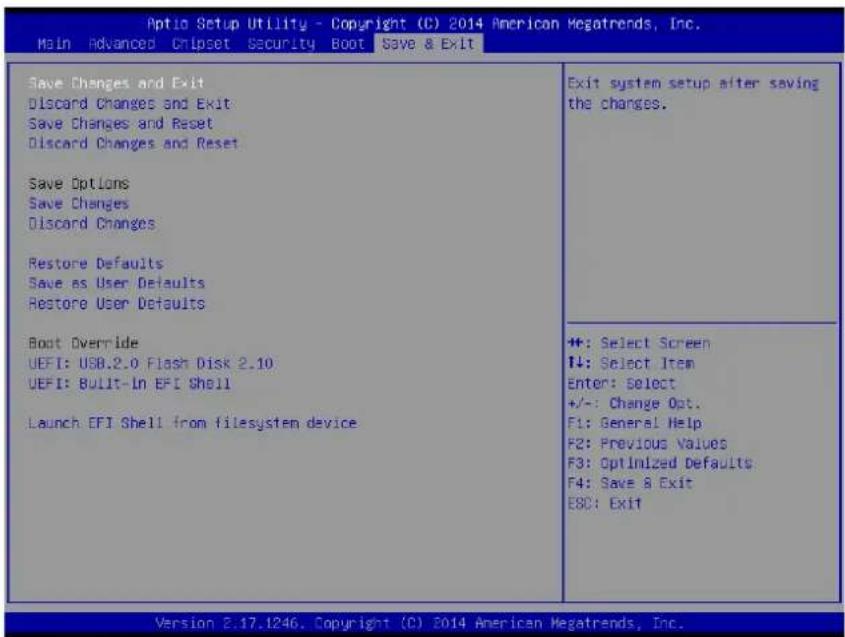
■ Save Changes and Exit
This item allows you to exit system setup after saving the changes.
■ Discard Changes and Exit
This item allows you to exit system setup without saving any changes.
■ Save Changes and Reset
This item allows you to reset the system after saving the changes.
■ Discard Changes and Reset
This item allows you to rest system setup without saving any changes.
Save Changes
This item allows you to save changes done so far to any of the options.
■ Discard Changes
This item allows you to discard changes done so far to any of the options.
Restore Defaults
This item allows you to restore/load default values for all the options.
■ Save as User Defaults
This item allows you to save the changes done so far as user defaults.
This item allows you to restore the user defaults to all the options.
■ Boot Override
Boot device select can override your boot priority.
■ Launch EFI Shell from files system device
Attempts to Launch EFI Shell application (Shell.efi) from one of the available file system devices.
ADVANTECH
Enabling an Intelligent Planet
www.advantech.com
Please verify specifications before quoting. This guide is intended for reference purposes only.
All product specifications are subject to change without notice.
No part of this publication may be reproduced in any form or by any means, electronic, photocopying, recording or otherwise, without prior written permission of the publisher.
All brand and product names are trademarks or registered trademarks of their respective companies.
© Advantech Co., Ltd. 2015

- TPC-1051WP/1551WP Series
- Copyright
- Acknowledgements
- Product Warranty (2 years)
- Declaration of Conformity
- CE
- FCC Class A
- Technical Support and Assistance
- Safety Instructions
- Caution!
- Chapter 1 General Information ....1
- Chapter 2 System Setup....9
- Chapter 3 Features in Windows Embedded .....17
- Appendix A Serial Port Settings 23
- Appendix B Driver Installation and Configuration..
- 33
- Appendix C BIOS Setup 59
- Chapter 1
- Introduction
- The key features are as follows:
- Specifications
- System Kernel
- I/O Ports
- O/S support
- Safety and Environment
- Safety
- Environment
- LCD Specifications
- Touchscreen Specifications
- Power
- I/O Ports Arrangement
- Panel Mounting
- Dimensions and Cutout
- TPC-1051WP Series
- TPC-1551WP Series
- Chapter 2
- System Setup
- Installing the Drivers
- Transport and Unpacking
- Panel Mounting
- Cabinet Installation and Earth Grounding setup
- Power/Digital Ground and Earth Ground
- Chapter 3
- Features in Windows Embedded
- Enhanced Write Filter (EWF)
- File-Based Write Filter (FBWF)
- HORM
- Enable EWF:
- Appendix A
- A.1 Jumper, Dip switch and Connector location
- A.1.1 Top
- A.1.2 Bottom
- A.2 Jumper setting and Description
- A.2.1 CMOS Clear Function (CN1)
- A.3 Switch Setting
- A.3.1 Termination Resistor Select (SW3)
- A.4 Connector Pin Definition
- A.4.1 SATA connector (CN12)
- A.4.2 SATA Power connector (CN13)
- A.4.3 Mini PCIE slot (MINIPCIE)
- A.4.4 CFast slot (CN14)
- A.4.5 Power in connector (CN18)
- A.4.6 LAN RJ45 connector (CN7, CN8)
- A.4.7 USB connector (CN10)
- A.4.8 COM1 RS232 connector (CN15)
- A.4.9 COM2 RS232/422/485 connector (CN16)
- Appendix B
- B.1 Intel Chipset Software Installation Utility Installation
- Click Next
- Click Accept
- Click Install
- Click Finish
- B.2 Intel Graphics Driver Installation
- Click Yes
- Click Next
- Click Install
- Click Next
- Choose Yes, then click Finish to restart
- B.3 LAN Driver Installation
- Click Install
- Click Finish
- B.4 Intel® Trusted Execution Engine Driver Installation
- Click Restart Now, then the system will restart
- Launch folder \TXE\TXE\_Win7\_X\_X.X\_X.X.X.XXXX 6. Install Setup TXE.exe
- Click Next
- Click Next
- B.5 Windows 7 USB 3.0 Driver Installation
- Click Next
- Choose Yes, then click Finish to restart
- B.6 Advantech EC Driver Installation
- 4.Click Install
- Choose Yes, then click OK to restart
- B.7 Advantech EC Brightness Control Tool Installation
- B.8 Advantech EC Watchdog Timer Driver Installation
- Choose Advantech [EC]WDT, then click Next
- Choose Yes, then click OK to restart
- Restarting Windows
- B.9 Advantech LMsensor Driver Installation
- Appendix C
- C.1 Entering Setup
- C.1.1 Main Setup
- ■ System time / System date
- C.1.2 Advanced BIOS Features Setup
- C.1.2.1 ACPI Settings Configuration
- ■ Enable ACPI Auto Configuration
- ■ Enable Hibernation
- ACPI Sleep State
- ■ Lock Legacy Resources
- C.1.2.2 Super I/O Configuration
- C.1.2.3 Embedded Controller Configuration
- C.1.2.4 S5 RTC Wake Settings
- ■ Wake system with Fixed Time
- C.1.2.5 Serial Port Console Redirection
- ■ Console Redirection
- C.1.2.6 CPU Configuration
- ■ Execute Disable Bit
- Intel Virtualization Technology
- C.1.2.7 Thermal Configuration
- Critical Trip Point
- ■ Passive Trip Point
- C.1.2.8 IDE Configuration
- Serial-ATA (SATA)
- ■ SATA Test Mode
- ■ SATA Speed Support
- SATA ODD Port
- SATA Mode
- Serial-ATA Port 0 / Port1
- ■ SATA Port 0 / Port1 HotPlug
- C.1.2.9 Miscellaneous Configuration
- OS Selection
- C.1.2.10 LAN Controller
- ■ LAN A Controller
- ■ LAN B Controller
- ■ Wake on LAN Enable
- C.1.2.11 CSM Configuration
- CSM Support
- GateA20 Active
- Option ROM Messages
- ■ Boot option filter
- Network
- Storage
- Video
- ■ Other PCI devices
- C.1.2.12USB Configuration
- ■ Legacy USB Support
- XHCI Hand-Off
- EHCI Hand-Off
- USB Mass Storage Driver Support
- ■ Device reset time-out
- ■ Device power-up delay
- C.1.3 Chipset Configuration
- Intel IGD Configuration
- C.1.3.1 Intel IGD Configuration
- GOP Driver
- C.1.4 Security
- C.1.5 Boot
- Setup Prompt Timeout
- ■ Bootup NumLock State
- Quiet Boot
- Fast Boot
- ■ Boot Option #1
- ■ Boot Option #2
- C.1.6 Save & Exit
- ADVANTECH
- www.advantech.com
Brand : Advantech
Model : TPC-1551WP
Category : Desktop computer