
FWA-3260 - Baby Scale Advantech - Free user manual and instructions
Find the device manual for free FWA-3260 Advantech in PDF.


| Product Type | Baby Scale |
| Brand | Advantech |
| Model | FWA-3260 |
| Dimensions (approx.) | 30 x 20 x 5 cm |
| Weight (approx.) | 2 kg |
| Power Supply | 2 x AA batteries (not included) |
| Measurement Units | kg / lb / oz |
| Maximum Capacity | 20 kg |
| Graduation | 10 g / 0.01 lb |
| Display | LCD, backlit |
| Tare Function | Yes (weigh baby with towel or blanket) |
| Hold Function | Yes (locks reading after weighing) |
| Auto-Off | After 60 seconds of inactivity |
| Low Battery Indicator | Yes |
| Overload Indicator | Yes |
| Platform Material | Plastic with non-slip mat |
| Safety Features | Rounded corners, stable base, anti-slip feet |
| Cleaning Instructions | Wipe with a damp cloth; do not immerse in water |
| Storage Conditions | Keep in a dry place, avoid extreme temperatures |
| Battery Replacement | Open battery compartment on bottom, replace with 2 x AA |
| Spare Parts Available | Battery compartment cover, non-slip mat (contact support) |
| Manual Language | English (PDF available for download) |
Frequently Asked Questions - FWA-3260 Advantech
User questions about FWA-3260 Advantech
0 question about this device. Answer the ones you know or ask your own.
Ask a new question about this device
Download the instructions for your Baby Scale in PDF format for free! Find your manual FWA-3260 - Advantech and take your electronic device back in hand. On this page are published all the documents necessary for the use of your device. FWA-3260 by Advantech.
USER MANUAL FWA-3260 Advantech
natural_image
Front view of a blue network switch device with ports and ventilation grilles (no visible text or labels)
natural_image
Abstract arrangement of yellow squares on white background (no text or symbols)Revision History
| Date[mm/dd/yyyy] | Revision | Modifications |
| 02/25/2016 | 0.1 | Initial version –draft- |
| 03/02/2016 | 0.2 | Update BIOS setup menu based on BIOS ver. 1.04 |
© Copyright 2014 – Advantech Co., Ltd.
All Rights Reserved
Advantech Co., Ltd. reserves the right to make improvements in the products described in this manual at any time without notice. No part of this manual may be reproduced, copied, translated or transmitted in any form or by any means without the prior written permission of Advantech Co., Ltd. Information provided in this manual is intended to be accurate and reliable. However, Advantech Co., Ltd. assumes no responsibility for its use, nor for any infringements of the rights of third parties, which may result from its use.
About this manual
Thank you for purchasing and using the Advantech FWA-3260.
The target audience of this manual includes users, administrators and technicians. This publication is a useful reference when installing, configuring, operating and managing the FWA-3260.
This manual is organized as follows:
• Section 1: Getting Started helps you with the first steps with the FWA-3260.
• Section 2: Product Specification provides a detailed description of the FWA-3260 and its features.
- Section 3: Configuration and Service describes how to change the FWA-3260's configuration or how to install and service replaceable items.
• Section 4: Tips, Tricks and Troubleshooting provides best practices and other information that may be helpful for operation and troubleshooting of the FWA-3260
- Appendices provide supplemental information referenced in the other sections of this document.
Useful documents
If you cannot find the information you're looking for or need more detailed information on a specific topic, please refer to the list of additional documents and other sources of information below. Please contact your Advantech representative if you need help on obtaining these documents or still can't find what you're looking for.
- Advanced LAN Bypass User Manual
- Advantech IPMI User Manual
- Information on intel CPUs, Chipsets and NIC silicon can be found at www.intel.com
- FWA-3260 Reference Platform Software User's Guide (for samples only)
Warnings, Cautions and Notes

Warning! Warnings indicate conditions, which, if not observed, can cause personal injury.

Caution! Cautions are included to help you avoid damaging hardware or losing data.

Note! Notes provide additional information.
We appreciate your input
Please let us know of any aspect of this product, including the manual, which could use improvement or correction. We appreciate your valuable input in helping make our products and documentation better.
Please send all such - in writing to: ncg@advantech.com
Acknowledgements
Xeon, QuickAssist and Intel are trademarked by Intel Corp. All other product names or trademarks are properties of their respective owners.
Table of Contents
1. GETTING STARTED.... 13
1.1 SAFETY INSTRUCTIONS.... 13
1.1.1 Safety Precautions per IEC704-1.... 13
1.1.2 Safety Precautions - Static Electricity.... 14
1.2 UNPACKING 14
1.3 INSTALLATION AND CONFIGURATION.... 16
1.3.1 Rack Mounting 16
1.3.2 Powering On.... 17
1.3.3 Connecting to the Console.... 17
1.3.4 Installing an OS....20
1.3.4.1 Pre-Installed reference OS 20
1.3.4.2 Installing and/or boot an OS from a USB key.... 20
1.3.4.3 Installing an OS via network boot 21
1.3.4.4 Booting an OS via network boot 21
1.4 GETTING HELP: TECHNICAL SUPPORT AND ASSISTANCE 25
2. PRODUCT SPECIFICATION ...... 26
2.1 OVERVIEW.... 26
2.2 PRODUCT VERSIONS 27
2.3 TECHNICAL SPECIFICATIONS 28
2.3.1 System dimensions.... 30
2.3.2 Regulatory Compliance 30
2.3.2.1 Safety.... 30
2.3.2.2 Electromagnetic Compatibility.... 30
2.3.2.3 CE Mark 31
2.4 DETAILED DESCRIPTION.... 31
2.4.1 Front elements.... 31
2.4.1.1 LED details.... 32
2.4.2 Rear Elements 32
2.4.3 System block diagram 33
2.4.4 Processor(s).... 33
2.4.5 Memory.... 34
2.4.6 Chipset.... 35
2.4.6.1 USB 35
2.4.6.2 SATA 36
2.4.6.3 Legacy Functions and IO.... 37
2.4.7 Network interfaces (onboard) 38
2.4.8 PCIe Expansion 38
2.4.9 TPM Module....39
2.4.10 LCD Module 39
2.4.11 Mass Storage.... 39
2.4.12 BIOS.... 40
2.4.12.1 Password protection 40
2.4.12.2 BIOS defaults 41
2.4.12.3 PCIe Tree.... 41
2.4.13 Platform Management.... 42
2.4.14 Power Supplies 45
2.4.14.1 Product Labelling.... 45
2.4.14.2 Electronic label: FRU EEPROM.... 47
2.5 ADVANCED PLATFORM FEATURES 48
2.5.1 Intrusion detection.... 48
2.5.2 Watchdog 48
2.5.3 LAN Bypass....48
2.5.3.1 LAN Bypass Segments 49
2.5.3.2 Bypass Watchdog Support 49
2.5.3.3 LED Behaviour 49
2.6 AVAILABLE ACCESSORIES AND RELATED PRODUCTS....50
2.6.1 Accessories....50
3. CONFIGURATION AND SERVICE....51
3.1 JUMPER SETTINGS....51
3.2 BIOS SETUP MENU....51
3.2.1 Main Setup Menu....52
3.2.1.1 Setting System Time and Date 53
3.2.2 Platform Setup Menu....54
3.2.2.1 Serial Port Console Redirection....54
3.2.2.2 USB Configuration....56
3.2.2.3 Trusted Computing 58
3.2.2.4 H/W Monitor....60
3.2.2.5 Virtualization....60
3.2.2.6 Platform Management.... 61
3.2.3 Hardware....63
3.2.3.1 Hardware Setup: CPU Configuration 64
3.2.3.2 Hardware Setup: North Bridge Configuration....66
3.2.3.3 PCI Express Port Configuration 67
3.2.3.4 QPI Configuration....68
3.2.3.5 Hardware Setup: South Bridge Configuration....70
3.2.3.6 USB Configuration 72
3.2.3.7 ACPI Setting....72
3.2.3.8 Runtime Error logging 73
3.2.4 Server Mgmt....74
3.2.5 Security Setup 76
3.2.6 POST & Boot Menu 76
3.2.6.1 Compatibility Support Module (CSM) Configuration....78
3.2.7 Save & Exit Menu.... 79
3.3 INSTALLING COMPONENTS 80
3.3.1 Removing the top cover 80
3.3.2 Reinstalling the top cover 81
3.3.3 Disk Installation....81
3.3.3.1 2.5" HDD drive....81
3.3.3.2 M.2 SSD 86
3.3.4 Memory Installation....87
3.4 FIRMWARE UPGRADES....90
3.4.1 BIOS....90
3.4.2 LAN Bypass....90
3.5 REPLACING FRUS....90
3.5.1 Disk drives 90
3.5.1.1 2.5" HDD....91
3.5.1.2 M.2 SSD....91
3.5.2 CMOS Battery....91
3.5.3 DIMMs....92
A. APPENDIX: CONNECTOR PINOUT AND LED INFORMATION....94
B. BIOS POST CODES....97
C. APPENDIX: POWER SUPPLY SPECIFICATION 103
D. APPENDIX: DECLARATION OF CONFORMITY 104
E. APPENDIX: WARRANTY AND RMA.... 105
List of Figures
Figure 1 : Mounting ear thread holes .... 16
Figure 2: Mounting ear screws inserted but not fastened yet ....16
Figure 3: PuTTY Session Configuration ....18
Figure 4: PuTTY Serial Configuration .... 18
Figure 5: PuTTY Keyboard Settings....19
Figure 6: PuTTY Colour Settings....19
Figure 7: BIOS POST screen (example)....20
Figure 8: System Overview....27
Figure 9: System Dimensions .... 30
Figure 10: System Front View....31
Figure 11: Front LEDs 32
Figure 12: System Rear View 32
Figure 13: Block diagram....33
Figure 14: DIMM Location....35
Figure 15: m.2 SSD 36
Figure 16: Mass storage components....40
Figure 17: Thermal Sensor Locations....44
Figure 18: Type Label (bottom) 45
Figure 19: Product Labels (internal) 46
Figure 20: Connectivity options of LAN ports in a bypass segment....48
Figure 21: Onboard LAN ports and bypass segments....49
Figure22: BIOS POST screen (example)....51
Figure 23: BIOS Setup Screen Organization ....52
Figure 24: BIOS Setup Main screen....52
Figure25: Platform Setup Main screen 54
Figure 26: Platform Setup: Console Redirection Menu ....55
Figure 27: Platform Setup: USB Configuration Menu....57
Figure 28: Platform Setup: Trusted Computing ....58
Figure 29: Platform Setup: Trusted Computing with TPM2.0....59
Figure 30: Platform Setup: H/W monitor 60
Figure 31: Platform Setup: Virtualization ....61
Figure 32: Platform Setup: Platform Management....62
Figure 33: Hardware Configuration Menu 64
Figure 34: Chipset: Processor Configuration Menu....65
Figure 35: NorthBridge Configuration Menu 66
Figure 36: Hardware Setup: PCI Subsystem 67
Figure 37: Hardware Setup: QPI configuration ....69
Figure 38: Hardware Setup: South Bridge configuration....70
Figure 39: Hardware Setup: SATA configuration ....71
Figure 40: Hardware Setup: USB configuration 72
Figure 41: Hardware Setup: ACPI configuration ....73
Figure 42: Hardware Setup: Runtime Error logging configuration ....74
Figure 43: Server Mgmt configuration....75
Figure 44 Boot Configuration ....77
Figure 45: Post & Boot Setup: CSM Configuration Menu....78
Figure 46: Save & Exit Menu 79
Figure 47: Top cover screw locations (left/rear/right)....80
Figure 48: Slide Top Cover back....81
Figure 49: Top Cover Flange Disengagement....81
Figure 50: Screws for HDD mounting....81
natural_image
Abstract arrangement of yellow squares on white background (no text or symbols)
Figure 51: HDD Carrier plate dampeners....82
Figure 52: Carrier plate and HDD alignment....82
Figure 53: Screw Insertion and fastening....83
Figure 54: HDD Carrier plate screw locations ....83
Figure 55: Insertion of the carrier into the chassis....84
Figure 56: SATA cabling....85
Figure 57: SATA Connector keying....85
Figure 58: HDD Power cable....86
Figure 59: M.2 SSD mounting screw 86
Figure 60: m.2 SSD key alignment 87
Figure 61: M.2 SSD angled insertion....87
Figure 62: M.2 SSD mounting....87
Figure 63: Opening DIMM latches....88
Figure 64: DIMM key alignment 88
Figure 65: DIMM insertion into slide rails 89
Figure 66: Seating the DIMM in the socket....89
Figure 67: Unlocking the battery....92
Figure 68 Battery Polarity 92
Figure 69: Unlocking and removing a DIMM 93
Figure 70: RJ45 Console connector....94
Figure 71: Stacked USB Type A connector 95
Figure 72: RJ45 10/100/1000 Base-T connector .....95
List of Tables
Table 1: Packaging List .... 15
Table 2: PXE BIOS Options....22
Table 3: System components ...... 27
Table 4: Available Product Versions....27
Table 5: Specifications....29
Table 6: Applicable Safety Regulations....30
Table 7: Applicable EMC Regulations ...... 31
Table 8: Front elements ...... 32
Table 9: Rear elements ...... 32
Table 10: Xeon D SKUs for Network and Enterprise Storage Infrastructure....34
Table 11: DIMM mapping....35
Table 12: Validated DIMMs....35
Table 13: USB Ports....35
Table 14: SATA Ports 36
Table 15: Validated SATA drives....37
Table 16: COM Ports ...... 37
Table 17: SMBus Devices....38
Table 18: PCIe devices....42
Figure 19: Display of CPU temperature 44
Table 20: Thermal Sensors ....45
Table 21: Product Labels ...... 47
Table 22: FRU Data Synced to the DMI Tables....47
Table 23: Bypass States and LED behaviour....50
Table 24: Accessories ....50
Table 25: BIOS Setup: Main Menu....53
Table 26: Platform Setup: COM1 Console Redirection Menu Items....56
Table 27: USB Configuration Menu ....58
Table 28: Trusted Computing Menu 58
Table 29: Trusted Computing Menu with TPM2.0....60
Table 30: Virtualization Menu....61
Table 31: Platform Management Menu ....63
Table 32: Processor Configuration Menu 65
Table 33: Northbridge Configuration Menu 67
Table 34: Hardware Setup: PCI Subsystem Menu Items 68
Table 35: Hardware Setup: QPI configuration Menu Items ...... 69
Table 36: Hardware Setup: South Bridge configuration Menu Items....71
Table 37: Hardware Setup: SATA configuration Menu Items....71
Table 38: Hardware Setup: USB configuration Menu Items....72
Table 39: Hardware Setup: ACPI configuration Menu Items....73
Table 40: Hardware Setup: Runtime Error logging Menu Items....74
Table 41: Server Mgmt configuration Menu Items....75
Table 42 Boot Configuration ....77
Table 43: CSM Configuration Menu....78
Table 44: Save & Exit Menu Options 80
Table 45: Console connector pin assignment ..... 94
Table 46: Stacked USB Type A connector pin assignment....95
Table 47: RJ45 10/100/1000 Base-T connector pin assignment....96
Table 48: RJ45 connector LED indication 96
Table 49: BIOS POST Codes ....102
Table 50: Single AC Power Supply Specification .... 103

natural_image
Abstract arrangement of yellow squares on white background (no text or symbols)Glossary
ACPI Advanced Configuration and Power Interface
AHCI Advanced Host Controller Interface
APIC Advanced Programmable Interrupt Controller
BIOS Basic Input Output System
BMC Baseboard Management Controller
CPU Central Processing Unit
EHCI Enhanced Host Controller Interface
FRU Field Replaceable Unit
FW Firmware
GbE Gigabit Ethernet
HPM Hardware Platform Management
HWM Hardware Monitor (chip)
IPMC Intelligent Platform Management Controller
IPMI Intelligent Platform Management Interface
LOM Lights Out Management
MAC Media Access Control
MTBF Mean Time Between Failures
NIC Network Interface Controller
NMC Network Mezzanine Card
NVRAM Non-volatile Random Access Memory
OOS Out Of Service
PCH Platform Controllers Hub
PCIe PCI Express
PECI Platform Environment Control Interface
PCI SIG PCI Special Interest Group
PICMG PCI Industrial Computer Manufacturers Group
POST Power On Self Test
PSU Power Supply Unit
PXE Pre-boot Execution Environment
QAT QuickAssist Technology
QPI QuickPath Interconnect
RASUM Reliability, Availability, Serviceability, Usability, Maintainability
RDIMM Registered DIMM
RMCP Remote Management Control Protocol
RX Receive
SAS Serial Attached SCSI
SATA Serial Advanced Technology Attachment
SCSI Small Computer System Interface
SDR Sensor Data Record
SerDes Serializer/Deserializer
SOL Serial Over LAN
SSD Solid State Disk
SW Software
TPM Trusted Platform Module
TX Transmit
UDIMM Unbuffered DIMM
UHCI Universal Host Controller Interface
USB Universal Serial Bus

natural_image
Abstract arrangement of yellow squares on white background (no text or symbols)1. GETTING STARTED
1.1 Safety Instructions
This section provides warnings that precede potentially dangerous procedures throughout this manual. Instructions contained in the warnings must be followed during all phases of operation, service, and repair of this equipment. You should also employ all other safety precautions necessary for the operation of the equipment in your operating environment. If you are not sure about the precautions applicable to your operating environment, please contact your company's safety administrator. For basic information you may also refer to the safety precautions per IEC704-1 listed below although Advantech disclaims all responsibility for the accuracy of any statements contained therein and its applicability for your specific environment.
Failure to comply with these precautions or with specific warnings elsewhere in this manual could result in personal injury or damage to the equipment.
Advantech intends to provide all necessary information to install and handle the FWA-3260 in this manual. Because of the complexity of this product and its various uses, we do not guarantee that the given information is complete. If you need additional information, contact your Advantech representative.
The product has been designed to meet the standard industrial safety requirements. It must not be used except in its specific area as specified in section 2.3.
Only personnel trained by Advantech or persons qualified in electronics or electrical engineering are authorized to install, service or maintain the product. The information given in this manual is meant to complete the knowledge of a specialist and must not be used as replacement for qualified personnel. Operating personnel must not remove equipment covers. Only factory authorized service personnel or other qualified service personnel may remove equipment covers for internal subassembly or component replacement or any internal adjustment.
Do not install substitute parts or perform any unauthorized modification of the equipment or the warranty may be voided. Contact your local Advantech representative for service and repair to make sure that all safety features are maintained.
1.1.1 Safety Precautions per IEC704-1
- Read these safety instructions carefully.
- Keep this User Manual for later reference.
- Keep this equipment away from humidity.
- Put this equipment on a reliable surface during installation. Dropping it or letting it fall may cause damage.
- Make sure the voltage of the power source is correct before connecting the equipment to the power outlet.
- Position the power cord so that people cannot step on it. Do not place anything over the power cord.
- All cautions and warnings on the equipment should be noted.
- If the equipment is not used for a long time, disconnect it from the power source to avoid damage by transient over-voltage.
- Never pour any liquid into an opening. This may cause fire or electrical shock.
- For safety reasons, the equipment should be opened only by qualified service personnel.
- If one of the following situations arises, get the equipment checked by service personnel:
- The power cord or plug is damaged.
- Liquid has penetrated into the equipment.
-
The equipment has been exposed to moisture.
-
The equipment does not work well, or you cannot get it to work according
- The equipment has been dropped and damaged.
- The equipment has obvious signs of breakage.
- DO NOT LEAVE THIS EQUIPMENT IN AN ENVIRONMENT WHERE THE STORAGE TEMPERATURE MAY GO BEYOND THE RANGE SPECIFIED IN Technical Specifications. THIS COULD DAMAGE THE EQUIPMENT. THE EQUIPMENT SHOULD BE IN A CONTROLLED ENVIRONMENT.
- CAUTION: DANGER OF EXPLOSION IF BATTERY IS INCORRECTLY REPLACED. REPLACE ONLY WITH THE SAME OR EQUIVALENT TYPE RECOMMENDED BY THE MANUFACTURER, DISCARD USED BATTERIES ACCORDING TO THE MANUFACTURER'S INSTRUCTIONS.
- The sound pressure level at the operator's position according to IEC 704-1:1982 is no more than 70 dB (A).
DISCLAIMER: The set of instructions is given according to IEC704-1. Advantech disclaims all responsibility for the accuracy of any statements contained herein.
1.1.2 Safety Precautions - Static Electricity
Follow instructions below to protect yourself from harm and the products from damage:
- Be sure you are at an ESD workstation, or grounded with an ESD strap before opening the top cover or installing/removing any unit accessible from the outside. Doing so will discharge any static electricity that might have built up in your body.
- Don't touch any components inside the system while the system is on.
- Disconnect power before making any configuration changes. The sudden rush of power as you connect a jumper or install a card may damage sensitive electronic components.
- When unpacking a static-sensitive component from its shipping carton, do not remove the component's antistatic packing material until you are ready to install the component in the unit.
- When transporting any electrical component, first place it in an antistatic container or packaging.

1.2 Unpacking
Please check the delivery for completeness as you open the carton carefully. If any of the items listed in Table 1 is missing or damaged, please contact your Advantech representative.
When opening the box, you will find the FWA-3260 embedded in protective foam and the accessory box embedded to the foam. Remove the accessory box first and then pull out the unit including the protective foam using both hands. Now, remove the foam and the plastic sleeve on the unit.
After unpacking the unit, please check for any visible damage of the unit and contact your Advantech representative in case of any issue.
Please note that unless agreed otherwise power cords need to be ordered separately. Please refer to section 2.6 for ordering information.
| Item | Qty. | Image | Description | |
| Network ApplianceFWA-3260 | 1 | 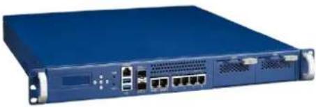 | 1U Middle-Range Network Appliance based on Intel® XeonTM D processors System On Chip | |
| Console cable | 1 | 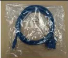 | Adapter cable RJ45 to DB9 2m for RS232. | |
| HDD Carrier plate | 1 | 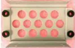 | Carrier Plate for 2.5” HDD | |
| HDD Carrier Screw Set | 1 | 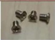 | Screws (4pcs) for mounting the HDD carrier plate inside the chassis | |
| m.2 Screw | 2 | 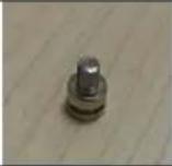 | Screw for m.2 SSD mounting | |
| SATA Cable | 1 | 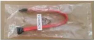 | SATA Cable for HDD connection | |
| Mounting Ears | 2 |  | Mounting Ears for Rack mounting | |
| Mounting Ear Screw Set | 1 |  | Screws (6pcs) for mounting the ears on the chassis | |
Table 1: Packaging List
1.3 Installation and Configuration
The FWA-3260 comes as a pre-configured system with CPUs, memory and peripherals installed in the unit. In the rare case that you procured a barebone system or need to install components in the FWA-3260 for any other reason, please refer to section 3.
1.3.1 Rack Mounting
The FWA-3260 appliance is designed to be installed in a standard 19-inch rack. Please follow the basic guidelines below for rack mounting:
- Mount the mounting ears on the each side of the unit using the screws included.
1) Locate the threaded mount holes on the chassis on the side, close to the front panel

natural_image
Front view of a blue computer monitor with ventilation slots and a circular logo on the left (no visible text or symbols)Figure 1: Mounting ear thread holes
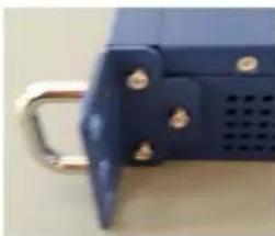
2) Place the mounting ear over the holes and insert the three screws. Do not tighten the screws immediately.
natural_image
Close-up of a blue plastic door with metal bracket and screw holes (no text or symbols visible)Figure 2: Mounting ear screws inserted but not fastened yet
3) After all screws have been inserted, hand tightened them using a PH2 screw driver to ensure secure installation.
- Ensure the rack is adequate for the unit (weight) and the application.
- Use the mounting hardware recommended by the rack manufacturer to mount the unit in the rack. Four mounting screws, compatible with the rack design, must be used and hand tightened to ensure secure installation
- While Advantech does not supply support brackets, slide rails are available for separate order. Please refer to section 2.6 for options.
- Choose a mounting location where all four mounting holes line up with those of the mounting bars of the 19-inch cabinet.
- Choose a mounting location that does not block any air inlet and air outlet areas of the unit, It is also recommended to factor in heat generated by adjacent equipment and to avoid exposure to direct sunlight when mounting the unit. If installed in a closed or multi-unit rack assembly, the operating ambient temperature of the rack environment may be greater than room ambient. Therefore, consideration should be given to installing the equipment in an environment compatible with the maximum recommended ambient temperature per section 2.3.
- Route cables away from power lines, fluorescent lighting fixtures and sources of noise.
Make sure that cables do not block air inlet and outlet areas. 8. Reliable grounding of rack-mounted equipment must be maintained.
1.3.2 Powering On
Before connecting the FWA-3260 to the power outlet, please make sure that the power rating of the outlet and the FWA-3260's PSU match. Please also make sure that the primary circuit and all power distribution in not overloaded. Inrush current and steady state power specifications for the FWA-3260 can be found in appendix C as well as the type label on the bottom of the unit.
Connect the power cord to the PSU module and then to the power outlet. The System has a DC on/off button next to the power connector.
The unit will automatically power on after power is supplied and push the DC on/off button to on position one times. The green LED on the front panel should be lit as the unit is under power.
Please refer to section 2.4 for the location of front and rear panel elements.
1.3.3 Connecting to the Console
FWA-3260 does not provide an interface for an external monitor in the standard configuration. BIOS output as well as OS output are provided via a serial terminal connection by default.
The remainder of this section describes how to configure PuTTY on a Windows platform for connection with the FWA-3260 serial console as a reference. Other terminal programs may be used in a similar way as well.
Open up PuTTY and begin the configuration as shown below. Please use the actual COM port's number on the client machine instead of "COM1".
- Specify "COM1" under serial line and "115200" for speed, no parity, no flow control.
- Check Serial for connection type.
- Check "VT100+" for keypad in the keyboard submenu
- Check "Colour" or "Both" for "Indicate bolded text" in the colours submenu
- Click the "Open" button and a PuTTY terminal screen will appear.

natural_image
Abstract pattern of overlapping yellow squares on white background (no text or symbols)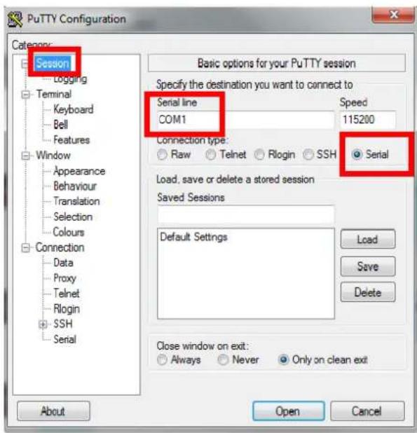
Figure 3: PuTTY Session Configuration
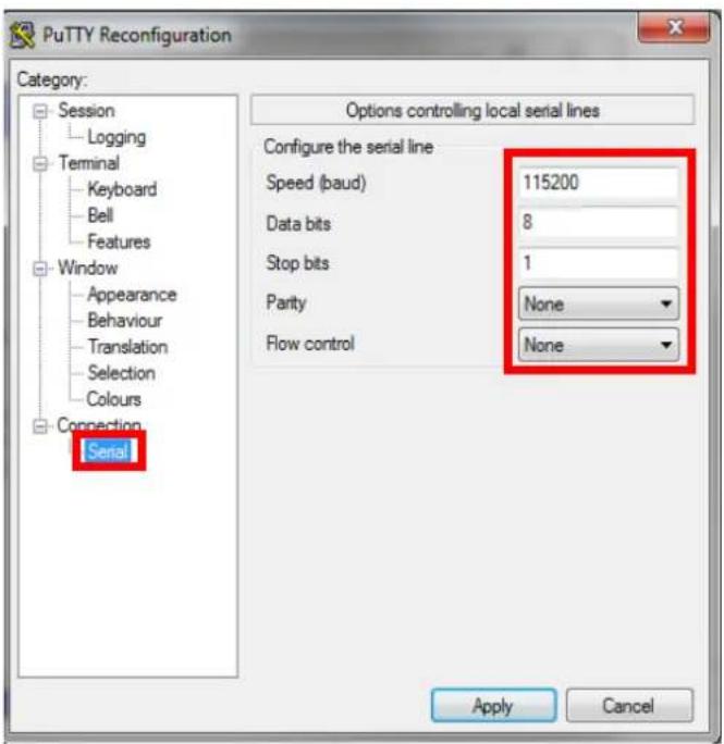
Figure 4: PuTTY Serial Configuration

natural_image
Abstract arrangement of yellow squares on white background (no text or symbols)![PuTTY Reconfiguration Category: Session Logging Terminal Keyboard Bell Features Window Appearance Behaviour Translation Selection Colours Connection Serial Options controlling the effects of keys Change the sequences sent by: The Backspace key Control-H Control-? (127) The Home and End keys Standard nxvt The Function keys and keypad ESC[n~ Linear Xtem R6 VT400 VT100+ SCO] Application keypad settings: Initial state of cursor keys: Normal Application Initial state of numeric keypad: Normal Application NetHack Enable extra keyboard features: AltGr acts as Compose key Control-Alt is different from AltGr Apply Cancel](/content/2026/05/818837/images/74c19d4d34f7f5518b8c567d1b1934ca2dec188310a7331c4211f699dacfd6a8.jpg)
Figure 5: PuTTY Keyboard Settings
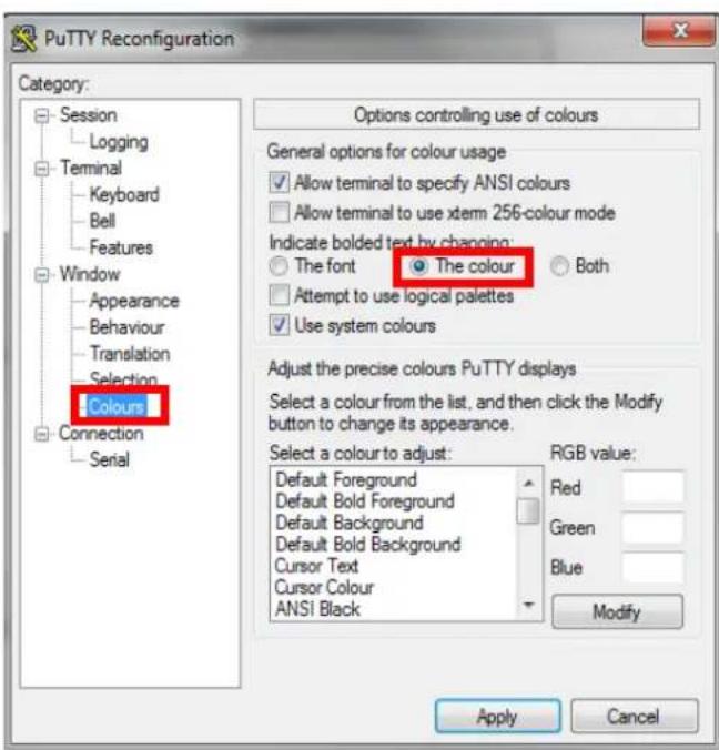
Figure 6: PuTTY Colour Settings
If the connection is successful you should be able to see the BIOS Power On (POST) screen after powering the unit:
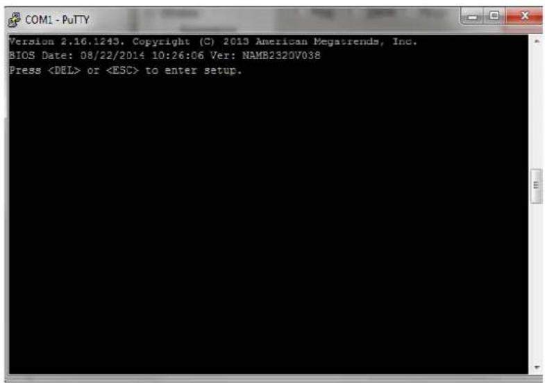
Figure 7: BIOS POST screen (example)
Please note that the BISO is doing some initial start up work while the console is still not active. It may take a while until the BIOS POST screen appears. On the other hand, the BIOS has been optimized for minimum boot time. The BIOS will move through POST quickly and immediately try to boot an OS according to the selected boot options in the BIOS:
In case you would extend the time the BIOS displays the POST screen and waits for a key press to enter the setup menu, you can do so via the BIOS setup menu. Please refer to section 3.2 for details.
1.3.4 Installing an OS
Several options are available for OS installation:
- System comes with a preinstalled OS
- Install an image from a USB key
- Install an OS via network boot.
If you use Advantech's services to pre-install an OS, you can skip the following section.
1.3.4.1 Pre-Installed reference OS
If you receive this manual along with a sample unit, the system will have a reference OS installed by default. The unit will be ready to boot the reference OS from the mass storage option selected.
1.3.4.2 Installing and/or boot an OS from a USB key
To install an OS via USB and/or boot the appliance from an USB stick, please make sure the following BIOS options are configured properly:
Advanced Setup: USB Configuration: Mass Storage Driver = Enabled
To boot from a USB stick:
1) Create a Live USB stick using LiLi (available via http://www.linuxliveusb.com/) or a similar tool. Please make sure to configure the Linux for the operation with a serial console (115200bd, 8N1, no handshake). Enabling serial support in the Linux bootloader (grub or similar) as well as kernel debug messages via serial console may be valuable for potential troubleshooting.
2) Install the USB stick in one of the front ports. Make sure you have a serial console connection established via tools such as PuTTY as described earlier.
3) Power on the appliance.
4) The boot priority in the FWA-3260's BIOS is giving SATA devices higher priority than USB devices. This is a safety measure to avoid that any end user can tamper the unit when installed in the field with a bootable USB stick. So, in order to boot from the USB stick, you need to enter BIOS setup.
In BIOS setup menu, move to the "Boot" menu. You can either give the USB stick higher boot priority over SATA devices. Alternatively, you can select the USB stick in the "Boot Override" Menu. Boot Override will modify the boot order for a single boot process only and will automatically revert back to the original boot priority. After making these changes leave the Setup Menu via "Save&Exit".
This will restart the appliance and it will boot from the USB stick.
1.3.4.3 Installing an OS via network boot
To install an OS via network, basically works the same way as booting an OS via USB stick described above.
The main difference is that instead of a Linux live image you need to install a network installer / a network installable image on the USB key. Network Installers or network installable iso images are available for most Linux distributions such as RedHat, Debian, Ubuntu and CentOS. For detailed information, please refer to the documentation of the related network installer and / or Linux distribution.
Please make sure you configure the network installer image properly for the Ethernet port / device of the FWA-3260 that you plan to sue for the installation.
1.3.4.4 Booting an OS via network boot
The FWA-3260 supports booting over network via PXE.
To boot an OS via network, please make sure the following BIOS options In the Advanced: Network Stack Configuration Menu are configured properly:
| Network Stack | Enabled | Enables the UEFI Network Stack. |
| IPv4 PXE Support | EnabledDisabled | Enabled if PXE booting in an IPv4 network;disabled otherwise |
Table 2: PXE BIOS Options
Below are the steps to enable PXE boot.
- It needs to set BIOS/ Advanced-> Network Stack Configuration-> Network Stack as enabled (default setting is disabled)
![Aptio Setup Utility - Copyright (C) 2016 American Megatrends, Inc. Main Platform Hardware Post & Boot Security Save & Exit Setup Prompt Timeout 1 Bootup NumLock State [On] Quiet Boot [Disabled] Network Stack [Disabled] Boot Option Priorities Boot Option #1 [UEFI: Built-in EFI ...] CSM16 Parameters CSM Parameters Enable/Disable UEFI Network Stack <<: Select Screen : Select Item Enter: Select +/-: Change Opt. F1: General Help F2: Previous Values F3: Optimized Defaults F4: Save & Exit ESC: Exit Version 2.17.1255. Copyright (C) 2016 American Megatrends, Inc.](/content/2026/05/818837/images/7afb4c26835f6127f7fcad5e1591a55deb635e154045746c811b2c5774128fb8.jpg)
- When set Network Stack is enabled, and then go to item of "BIOS/ Advanced->CSM Parameters -> Network" to enable PXE ROM function, set it as "Legacy" (IPV4 PXE) function.
![Aptio Setup Utility - Copyright (C) 2016 American Megatrends, Inc. Post & Boot CSM Support [Enabled] Boot option filter [UEFI and Legacy] Network [Do not launch] Storage [Legacy] Video [Legacy] Other PCI devices [UEFI] Network Do not launch UEFI Legacy Controls the execution of UEFI and Legacy PXE OpROM <<: Select Screen : Select Item Enter: Select +/-: Change Opt. F1: General Help F2: Previous Values F3: Optimized Defaults F4: Save & Exit ESC: Exit Version 2.17.1255. Copyright (C) 2016 American Megatrends, Inc.](/content/2026/05/818837/images/b1d2b82ae04f1e40b610c3ae995e748b25e346578ee998c92005cc0a7fbdea1e.jpg)
- Save BIOS and reboot system. The BIOS will show "Checking Media Presence......", if system is not connected PXE server, it will show "No Media Present......"
BIOS Date: 11/13/2014 17:28:35 Ver: NAMB2320V044
Press <DEL> or <ESC> to enter setup.

>>Checking Media Presence......
>>No Media Present......

>>Checking Media Presence......
>>No Media Present......

>>Checking Media Presence......
>>No Media Present......

>>Checking Media Presence......
>>No Media Present......

>>Checking Media Presence......
>>No Media Present......

>>Checking Media Presence......
>>No Media Present......

>>Checking Media Presence......
>>No Media Present......

>>Checking Media Presence......
>>No Media Present......
- User may re-login in BIOS, choose BIOS/ boot item, it will has "Network Device BBS Priorities" item and set UEFI PXE LAN boot sequence priority.
![Aptio Setup Utility - Copyright (C) 2016 American Megatrends, Inc. Main Platform Hardware Server Mgmt Post & Boot Security Save & Exit Setup Prompt Timeout 1 Bootup NumLock State [On] Quiet Boot [Disabled] Network Stack [Enabled] Boot Option Priorities Boot Option #1 [F4: TS64GMTS600] Boot Option #2 [IBA XE Slot 0400 v2353] Boot Option #3 [UEFI: Built-in EFI ...] Network Device BBS Priorities Hard Drive BBS Priorities CSM16 Parameters CSM Parameters Set the order of the legacy devices in this group <<: Select Screen : Select Item Enter: Select +/-: Change Opt. F1: General Help F2: Previous Values F3: Optimized Defaults F4: Save & Exit ESC: Exit Version 2.17.1255. Copyright (C) 2016 American Megatrends, Inc.](/content/2026/05/818837/images/f564af55b1aec00f20f27f25aeba6f65b36d0800133b94845aaa6df19bb64401.jpg)
And please choose PXE Boot priority as "IBA GE Slot 0A00 v1570" it is on board Mgmt GbE port.
![Aptio Setup Utility - Copyright (C) 2016 American Megatrends, Inc. Post & Boot Boot Option #1 [IBA XE Slot 0400 v2353] Boot Option #2 [IBA XE Slot 0401 v2353] Boot Option #3 [IBA GE Slot 0A00 v1570] Sets the system boot order ><: Select Screen : Select Item Enter: Select +/-: Change Opt. F1: General Help F2: Previous Values F3: Optimized Defaults F4: Save & Exit ESC: Exit Version 2.17.1255. Copyright (C) 2016 American Megatrends, Inc.](/content/2026/05/818837/images/bc4f35c53e6ed89f98b778712b7ec0ff25f9e3320f9e8e8ced2073192aa95069.jpg)
PXE boot usually does not allow for OS installation over network as the PXE client will only load a single file from the boot server. Similarly, booting Linux over network is usually a two stage process. In the first step, a boot loader such a grub or mini OS such as SysLinux are loaded via PXE from the boot server. The boot loader or miniOS then load the actual target OS which usually consists of multiple files which decompressed and installed into a RAM disk. The detailed process and required configuration of such network install will heavily depend on the target OS and boot loader / miniOS used. Please refer to the related documentation available.
PXE boot requires a DHCP server and a TFTP server in the network to complete. DHCP Server and TFTP server are commonly run on the same machine and collectively referred to as "boot server". Setting up such a boot server implies a couple of steps. How-to guides for setting up Linux as PXE boot server are available on the internet, e.g. https://www.debian-administration.org/article/478/Setting_up_a_server_for_PXE_network_booting.
Please note that it is recommended to setup a separate network / subnet for network booting as the DHCP required for PXE booting may conflict with existing DHCP servers in your network.
The PXE client in the FWA-3260 sends the system's GUID as part of the DHCP Request. Some boot servers have mechanisms to automatically configure the target OS image based on the client system's GUID. Using this mechanism allows to use the same boot server for network booting of different devices / appliances.

1.4 Getting Help: Technical Support and Assistance
In case the unit you received is a sample for evaluation, please contact your Advantech representative. For production units, please follow the process below:
-
Visit the Advantech web site at www.advantech.com/support to find the latest information about the FWA-3260 and related products.
-
Contact your distributor, sales representative, or Advantech's customer service center for technical support if you need additional assistance. Worldwide contact information can be found on www.advantech.com.
-
Please have the following information ready before you call / be sure to include this information in your email:
◆ Product name and serial number
◆ Description of your peripheral attachments
◆ Description of firmware and software versions installed on the product
◆ A complete description of the problem
◆ The exact wording of any error messages
- In case the unit needs to be send back for repair, please refer to appendix E for instructions.
2. PRODUCT SPECIFICATION
2.1 Overview
The FWA-3260 1U network appliance features Intel's® Xeon® Processor D System On Chip to meet the need for higher core count, larger and faster memory as well as increased IO performance without sacrificing cost efficiency in a compact footprint. With up to 16 Xeon class cores and 1.5MB last level cache per core tightly integrated with DDR4 memory controllers and a rich IO subsystem, the Xeon® D SoC performs extremely well in applications tailored for multicore designs. Besides supporting memory capacities up to 128GB, Xeon® D also brings enhanced reliability and availability features previously only available on high end Xeon® E5 series processors into a midrange appliance footprint. Two integrated 10GE controllers with 128TX/RX queues per port, support for SR-IOV and optimizations for network overlays such as VxLAN and NVGRE as well as high performance PCIe gen.3 interfaces complement the processor subsystem of the SoC.
With an optimized system design the FWA-3260 adds four server class copper ports based on the Intel i350-AM4 Ethernet controller, Advanced LAN bypass capabilities as well as flexible, scalable and high performance port expansion via two PCIe gen.3 Network Mezzanine bays. Support for a PCIe8 gen.3 full height / half length card provides additional flexibility to integrate special purpose IO cards or QuickAssist™ offload adapters such as Advantech's PCIE-3215.
In the base configuration, the system comes with support for two 2.5" SATA HDDs/SSDs, two M.2 sockets, LCM, RJ45 console, two USB ports and two additional GbE management ports. While the FWA-3260A SKU is optimized for highest performance and system reliability supporting redundant, hot swap power supplies, the FWA-3260B is tailored for best cost in entry level applications.
Featuring an optional server BMC in accordance with IPMI2.0, the FWA-3260 supports state-of-the-art remote and lights-out management for increased reliability, serviceability and improved total cost of ownership. Advanced features such as power supply monitoring via PMBus allow the whole platform to be remotely managed. All management firmware can be remotely upgraded using the industry standard HPM.1 protocol, same as the motherboard system BIOS. All upgrades are fail safe and support instant rollback allowing for full system recovery without the necessity for onsite service staff.
The system is FCC,CE,CB,UL,CCC and RoHS compliant.
natural_image
Abstract pattern of yellow squares scattered on white background with a black horizontal line at bottom (no text or symbols)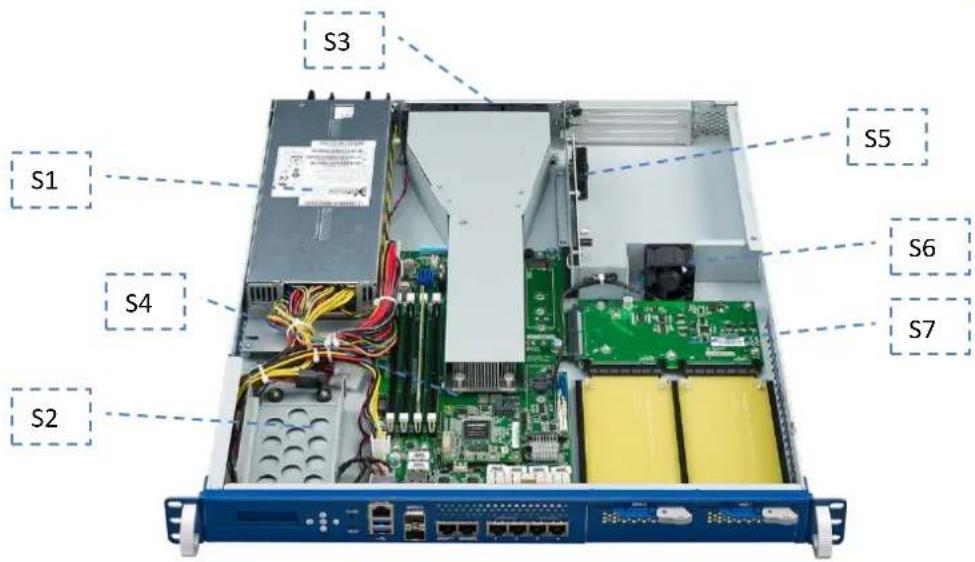
Figure 8: System Overview
| Component | Qty. | Description |
| S1 | 1 | PSU module |
| S2 | 1 | 2x 2.5” HDD bracket |
| S3 | 3 | Rear system cooling fan |
| S4 | 1 | NAMB-3260 Motherboard |
| S5 | 1 | PCIe expansion card mounting area |
| S6 | 1 | Inner fan |
| S7 | 1 | Middle board for NMCs |
Table 3: System components
2.2 Product Versions
The FWA-3260 is available in the following standard configurations. Contact your Advantech representative for availability of other configuration options.
| Model Name | Configurations |
| FWA-3260A-00E | Intel Xeon D-1528(6C), 6GbE + 2 10GE ports, red. AC PSU, 2 NMC bays, 4 DDR4 RDIMM sockets, up to 2400 MHz1 PCIEx8 riser card, 1 LOM (IPMI) |
| FWA-3260A-01E | Intel Xeon D-1548(8C), 6GbE + 2 10GE ports, red. AC PSU, 2 NMC bays, 4 DDR4 RDIMM sockets, up to 2400 MHz1 PCIEx8 riser card, 1 LOM (IPMI) |
| FWA-3260B-00E | Intel Xeon D-1508(2C), 6GbE + 2 10GE ports, single AC PSU, 2 NMC bays, 4 DDR4 RDIMM sockets, up to 2400 MHz |
| FWA-3260B-01E | Intel Xeon D-1527(4C), 6GbE + 2 10GE ports, single AC PSU, 2 NMC bays, 4 DDR4 RDIMM sockets, up to 2400 MHz |
Table 4: Available Product Versions
2.3 Technical Specifications
| FWA-3260A | FWA-3260B | ||
| Processor System | CPU L2 Cache | Intel® Xeon D up to 16 cores 1.5MB per core | Intel® Xeon D up to 4 cores 1.5MB per core |
| Memory | DIMM socket | 4 | |
| Technology | Dual channel DDR4-2400MHz ECC | ||
| Capacity | 64GB(UDIMM)/128GB(RDIMM) | ||
| PCIe | Expansion Slot | 1 x PCIe x8 riser cards Supports full-height/half-length cards | Without PCIe riser card |
| Ethernet | LAN on board | 4 x Intel I350-AM4 10/100/1000 Mbps Ethernet with optional 2 segment advanced bypass 2 x Intel I210-AT 10/100/1000 Mbps Ethernet for Management 2 x 10GbE SFP+ (integrated in Xeon® D) | |
| NMC modules | 2 x NMC modules with PCIex8 gen.3 interfaces Maximum 8 GbE ports, 4 10GE ports or 2 40GE ports Please refer to the "Recommended NMC Module List" section for a list of currently available NMCs | ||
| Storage | SATA3.0 | 2 x 2.5" Internal HDD/SSD | |
| Flash | 2 x M.2 sockets (1x 2280 or 2x 2240) | ||
| System management & Peripherals | USB | 2 x USB3.0 ports in the front 1 x USB2.0 ports on board | |
| Serial | 1 x RS232 Console port (RJ-45 connector) | ||
| LCD Module | 16 x 2 graphic display, 5 buttons | ||
| IPMI | LOM Module (optional) with Aspeed AST1250 chip | Without LOM module | |
natural_image
Abstract arrangement of yellow squares on white background, no text or symbols present| Supports IPMI 2.0, redundant BIOS and remote, failsafe BIOS update | |||
| TPM | Trust Platform Module (Optional) | ||
| Power supply | Watt | 300W redundant AC PSU (redundant DC PSUs on request) | 250W non-redundant AC PSU |
| Input | AC 100 ~ 240 V @ 50 ~ 6 Hz, full range PMBus support | AC 100 ~ 240 V @ 50 ~ 60 Hz, full range | |
| Environment | Temperature Humidity | Operating Non-operating | |
| 0 ~ 40 °C (32 ~ 104 °F)5 ~ 85%@40 °C (104 °F) | -20 ~ 80 °C (-4 ~ 167 °F)5 ~ 95 % | ||
| Physical | Dimensions | 430x500x44 mm (W x L x H), 17"x19.7"x 1.7" | |
| Weight(N.W) | 10 Kg (22lb) | ||
The "Recommended NMC Module List" section for a list of currently available NMCs
Recommended NMC Module List
| Part Number | NMC-0120 | NMC-0121 | NMC-0806 | NMC-1008 | NMC-4005 | NMC-4006 |
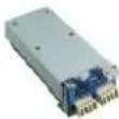 | 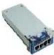 | 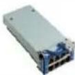 | 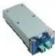 | 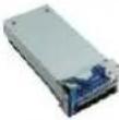 | 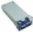 | |
| Description | 4-port GbE card | 4-port GbE card | 8-port GbE card | 2-port 10 GbE card | 4-port 10 GbE card | 2-port 40 GbE card |
| LAN Controller | 1 x Intel® I350-AM4 | 1 x Intel® I350-AM4 | 2 x Intel® I350-AM4 | 1 x Intel® 82599 | 1 x Intel® XL710 | 1 x Intel® XL710 |
| Ports | 4 x SFP | 4 x RJ45 | B x RJ45 | 2 x SFP+ | 4 x SFP+ | 2 x QSFP |
| Other | With LAN bypass | With LAN bypass | With LAN bypass | With LAN bypass | Without LAN bypass | Without LAN bypass |
For a full list of available / recommended NMC modules, please contact your Advantech representative.
Table 5: Specifications

natural_image
Abstract arrangement of yellow squares on white background (no text or symbols)2.3.1 System dimensions
The system dimensions (in mm) are shown below:
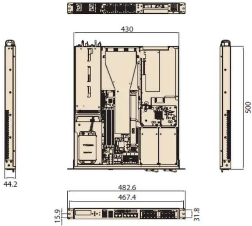
Figure 9: System Dimensions
2.3.2 Regulatory Compliance
The Advantech FWA-3260 meets the specifications and regulations for safety and EMC defined in this chapter. Please contact your Advantech representative for a copy of the declaration of conformity or detailed test reports.
2.3.2.1 Safety
| USA/Canada | UL 60950-1 2^nd Edition//CSA C22.2 No. 60950-1-07 2^nd Edition |
| Europe | EN 60950-1:2006/A11:2009/A1:2010/A12:2011EN 60950-1: A2:2013 |
| International | CB Certificate and Report to IEC60950-1, 2^nd Edition and all international deviations |
Table 6: Applicable Safety Regulations
2.3.2.2 Electromagnetic Compatibility
| USA | FCC 47 CFR Parts 15, Verified Class A Limit |
| Canada | ICES-003 Class A Limit |
| Europe | EMC Directive, 2004/108/ECEN55022, Class A Limit, Radiated & Conducted EmissionsEN55024 Immunity Characteristics for ITEEN61000-4-2 ESDImmunity EN61000-4-3Radiated ImmunityEN61000-4-4 ElectricalFast Transient EN61000-4-5 SurgeEN61000-4-6 Conducted RFEN61000-4-8 Power Frequency MagneticFields EN61000-4-11 Voltage Fluctuations |
| International | CISPR 22, Class A Limit, CISPR 24 Immunity |
Table 7: Applicable EMC Regulations
2.3.2.3 CE Mark
The CE marking on this product indicates that it is in compliance with the European Union EMC Directive 2004/108/EC, Safety Directive 2001/95/EC, Low Voltage Directive 2006/95/EC, and RoHS (recast) Directive 2011/65/EU.
2.4 Detailed Description
2.4.1 Front elements
Please refer to appendix A for a description of connector pin definitions.
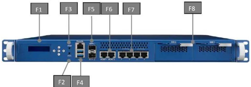
Figure 10: System Front View
| Item | Element | Description |
| F1 | LCM | Graphical LCD Module with 5 buttons |
| F2 | HDD LED | Hard disk activity LED (all SATA devices) |
| F3 | PWR LED | Power LED |
| F4 | Console + USB Connector | RS232 Console + Stacked Type A USB connector providing 2 USB2.0/3.0 ports |
| F5 | SFP+ Connector | 2 10G SFP+ |
| F6 | Management Port 0/1 | Management LAN Port 0/1 |
| F7 | Traffic Port 1~4 | Traffic LAN Port 1~4 |
| F8 | NMC slots | 2 NMCs slot for NICs expansion |
Table 8: Front elements

natural_image
Abstract arrangement of yellow squares on white background (no text or symbols)2.4.1.1 LED details
Two LEDs are provided at the front for signalling important system status at location F2 and F3.
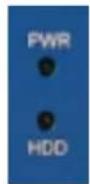
Figure 11: Front LEDs
The PWR LED is a green indicator which is lit when the unit is powered. The HDD activity LED is amber and indicates hard disk and M.2 activity.
2.4.2 Rear Elements
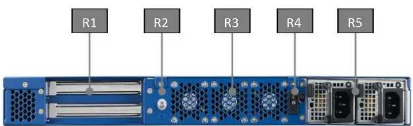
Figure 12: System Rear View
| Item | Element | Description |
| R1 | PCIE slots | 1 PCIEx8 for Add on card as default option |
| R2 | Grounding screws | Grounding connection |
| R3 | System fan | 3 Rear system fan exhaust |
| R4 | On/Off Button | Power DC on/off button |
| R5 | AC Power inlet | AC Power connector (2 skus with single and redundant PSU options) |
Table 9: Rear elements
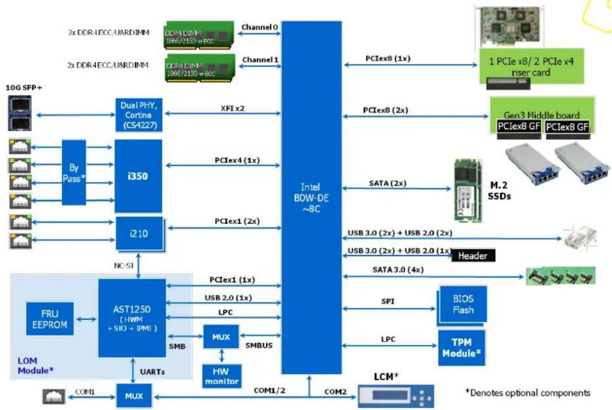
2.4.3 System block diagram
flowchart
graph TD
    A["10G SFP+"] --> B["Dual PHY, Cortina (CS4227)"]
    B --> C["i350"]
    C --> D["i210"]
    D --> E["AST1250 (HWM + SIO + IPMI)"]
    E --> F["MUX"]
    F --> G["HW monitor"]
    G --> H["COM1"]
    H --> I["MUX"]
    I --> J["COM1/2"]
    J --> K["COM2"]
    K --> L["LCM*"]
    L --> M["TPM Module*"]
    M --> N["BIOS Flash"]
    N --> O["SPI"]
    O --> P["Header"]
    P --> Q["USB 3.0 (2x) + USB 2.0 (2x)"]
    Q --> R["MT2 SSDs"]
    R --> S["Gen3 Middle board"]
    S --> T["PCIex8 GF"]
    T --> U["PCIex8 GF"]
    U --> V["1 PCIe x8/2 PCIe x4 riser card"]
    C --> W["XFI x2"]
    W --> X["PCIex4 (1x)"]
    X --> Y["PCIex1 (2x)"]
    Y --> Z["PClex1 (2x)"]
    Z --> AA["PClex4 (1x)"]
    AA --> AB["Intel BDW-DE ~8C"]
    AB --> AC["PCIex8 (1x)"]
    AC --> AD["PCIex8 (2x)"]
    AD --> AE["PClex8 (1x)"]
    AE --> AF["PCIex8 (2x)"]
    AF --> AG["PClex8 (1x)"]
    AG --> AH["PCIex8 (2x)"]
    AH --> AI["PClex8 (1x)"]
    AI --> AJ["PCIex8 (2x)"]
    AJ --> AK["PClex8 (1x)"]
    AK --> AL["PCIex8 (2x)"]
    AL --> AM["PClex8 (1x)"]
    AM --> AN["PCIex8 (2x)"]
    AN --> AO["PClex8 (1x)"]
    AO --> AP["PCIex8 (2x)"]
    AP --> AQ["PClex8 (1x)"]
    AQ --> AR["PCIex8 (2x)"]
    AR --> AS["PClex8 (1x)"]
    AS --> AT["PCIex8 (2x)"]
    AT --> AU["PClex8 (1x)"]
    AU --> AV["PCIex8 (2x)"]
    AV --> AW["PClex8 (1x)"]
    AW --> AX["PCIex8 (2x)"]
    AX --> AY["PClex8 (1x)"]
    AY --> AZ["PCIex8 (2x)"]
    AZ --> BA["PClex8 (1x)"]
    BA --> BB["PCIex8 (2x)"]
    BB --> BC["PClex8 (1x)"]
    BC --> BD["PCIex8 (2x)"]
    BD --> BE["PClex8 (1x)"]
    BE --> BF["PCIex8 (2x)"]
    BF --> BG["PClex8 (1x)"]
    BG --> BH["PCIex8 (2x)"]
    BH --> BI["PClex8 (1x)"]
    BI --> BJ["PCIex8 (2x)"]
    BJ --> BK["PClex8 (1x)"]
    BK --> BL["PCIex8 (2x)"]
    BL --> BM["PClex8 (1x)"]
    BM --> BN["PCIex8 (2x)"]
    BN --> BO["PClex8 (1x)"]
    BO --> BP["PCIex8 (2x)"]
    BP --> BQ["PClex8 (1x)"]
    BQ --> BR["PCIex8 (2x)"]
    BR --> BS["PClex8 (1x)"]
    BS --> BT["PCIex8 (2x)"]
    BT --> BU["PClex8 (1x)"]
    BU --> BV["PCIex8 (2x)"]
    BV --> BW["PClex8 (1x)"]
    BW --> BX["PCIex8 (2x)"]
    BX --> BY["PClex8 (1x)"]
    BY --> BZ["PCIex8 (2x)"]
    BZ --> CA["PClex8 (1x)"]
    CA --> CB["PCIex8 (2x)"]
    CB --> CC["PClex8 (1x)"]
    CC --> CD["PCIex8 (2x)"]
    CD --> CE["PClex8 (1x)"]
    CE --> CF["PCIex8 (2x)"]
    CF --> CG["PClex8 (1x)"]
    CG --> CH["PCIex8 (2x)"]
    CH --> CI["PClex8 (1x)"]
    CI --> CJ["PCIex8 (2x)"]
    CJ --> DA["PClex8 (1x)"]
    DA --> DB["PCIex8 (2x)"]
    DB --> DC["PClex8 (1x)"]
    DC --> DD["PCIex8 (2x)"]
    DD --> DE["PClex8 (1x)"]
    DE --> DF["PCIex8 (2x)"]
    DF --> DG["PClex8 (1x)"]
    DG --> DH["PCIex8 (2x)"]
    DH --> DI["PClex8 (1x)"]
    DI --> DJ["PCIex8 (2x)"]
    DJ --> DK["PClex8 (1x)"]
Figure 13: Block diagram
2.4.4 Processor(s)
The FWA-3260 supports one Xeon D processor. The table below gives an overview of the processor SKUs for Network and Storage infrastructure which can be supported on the FWA-3260:
| Prod. Avail. | LCC Standard Production (LCC) | HCC Standard Production (SKU definition in planning) | ||||||||||
| SKU # | Pentium D1507 | Pentium D1508 | Pentium D1517 | Xeon D-1518 | Xeon D-1527 | Xeon D-1528 | Xeon D-1537 | Xeon D-1548 | Xeon D-1557 | Xeon D-1567 | Xeon D-1577 | Xeon D-1587 |
| Core # | 2 | 2 | 4 | 4 | 4 | 6 | 8 | 8 | 12 | 12 | 16 | 16 |
| TDP | 20W | 25W | 25W | 35W | 35W | 35W | 35W | 45W | 45W | 65W | 45W | 65W |
| Core Freq. | ~1.2GHz | ~2.2GHz | ~1.6GHz | 2.2GHz | ~2.2GHz | ~1.9GHz | ~1.7GHz | ~2.0GHz | tbd | tbd | tbd | tbd |
| Max Turbo Freq. | - | ~2.5GHz | ~1.9GHz | - | ~2.5GHz | ~2.2GHz | ~2.0GHz | ~2.3GHz | tbd | tbd | tbd | tbd |
| Turbo | No | Yes | No | Yes | ||||||||
| HT | No | Yes | ||||||||||
| I/O | 24x PCIe3, 6x SATA3, 4x USB3.0, 4x USB2.0 | |||||||||||
| PSE | Yes (NTB, ADR, CBDMA) | |||||||||||
| Ethernet | 2x 10G (BaseT, iXF1 only) | 2x 10G (full POR interfaces) | 2x 10G (BaseT, iXF1 only) | 2x 10G (full POR interfaces) | 2x 10G (BaseT, iXF1 only) | 2x 10G (full POR interfaces) | ||||||
| Memory Type | ||||||||||||
| Memory Speed | Up to DDR4-1000 DDR3L-1333 | Up to DDR4-2133, DDR3L-1600 | Up to DDR4-2400, DDR3L-1600 | tbd | tbd | tbd | tbd | |||||
| eTEMP | No | |||||||||||
| Life/Reliability | 7yr / 10yr | |||||||||||
Table 10: Xeon D SKUs for Network and Enterprise Storage Infrastructure
Please note that the Xeon D is soldered on the motherboard and cannot be installed later. The standard product configurations available including CPU options are listed in section 2.2. If you're interested in the support of other CPU SKUs, please contact your Advantech representative.
For details on the features of the Xeon D processor, please refer to documentation available from Intel.

2.4.5 Memory
Four DDR4 RDIMMs or UDIMMs are supported on the FWA-3260. Both DIMMs reside on the CPU's memory channel A/B and can support operation up 2400MT/s (CPU SKU dependent).
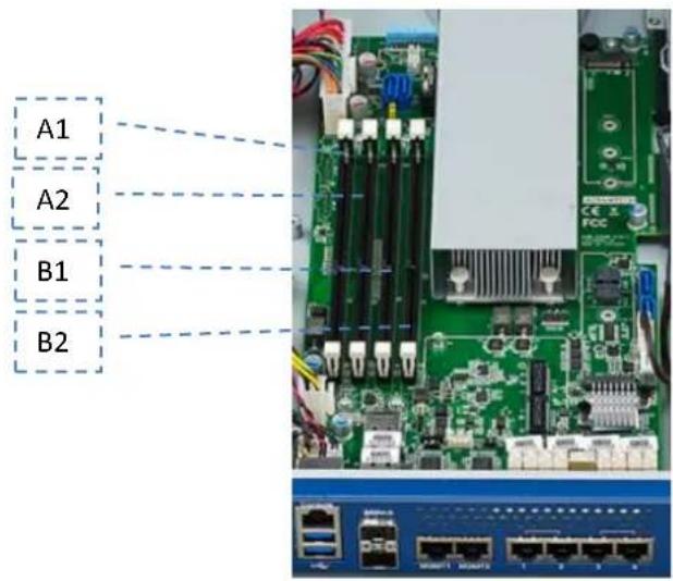
Figure 14: DIMM Location
| Location | DIMM | Channel | Color | SMBus Adr. |
| A0 | CN1 | A | Black | 0xA0 |
| A1 | CN2 | A | Black | 0xA2 |
| B0 | CN3 | B | Black | 0xA4 |
| B1 | CN4 | B | Black | 0xA6 |
Table 11: DIMM mapping
DIMM modules need to be populated in A1 or B1 as first priority. DDR4 modules will be recognized automatically. No manual adjustment is required.
It is recommended to use identical DIMMs on both sockets for best performance and reliability.
The following list summarizes the modules validated on the FWA-3260:
| Vendor | Frequency | Capacity | Advantech PN |
| Advantech | DDR4-2133 | 4G | AQD-D4U4GR21-SG |
| DDR4-2133 | 8G | AQD-D4U8GR21-SG | |
| DDR4-2133 | 16G | AQD-D4U16R21-SE |
Table 12: Validated DIMMs
Please contact you Advantech representative for the most recent list of validated peripherals or if you would like to use modules not listed.
2.4.6 Chipset
The chipset / PCH functionality is integrated into the Xeon D SoC.
2.4.6.1 USB
The FWA-3260 supports two external USB2.0/3.0 ports which can be used to connect low, full and high speed devices. The 5V supply rail supplied to external devices is current limited by a self resetting, electronic fuse to 500mA.
| USB Port | USB Type | Implementation |
| 0/1 | 2.0/3.0 | Type A front panel connector |
| 1/2 | 2.0/3.0 | Type A front panel connector |
| 3 | 2.0 | USB header (reserved) |
| 5/6 | 3.0 | USB header (reserved) |
Table 13: USB Ports

2.4.6.2 SATA
The PCH has two integrated SATA host controllers that support independent DMA operation and supports data transfer rates of up to 6.0 Gb/s (600 MB/s) on up to six ports while all ports support rates up to 3.0 Gb/s (300 MB/s) and up to 1.5 Gb/s (150 MB/s). The SATA controller contains two modes of operation—a legacy mode using I/O space, and an AHCI mode using memory space. Software that uses legacy mode will not have AHCI capabilities. Four SATA connectors and two M.2 connectors are implemented on motherboard design. The SATA ports are implemented per below table on the FWA-3260.
| System SATA Port | Implementation | Controller | Controller Port |
| 1 | SATA header 1 | SATA3 | Port 0 |
| 2 | SATA header 2 | SATA3 | Port 1 |
| 3 | SATA header 3 | SATA3 | Port 2 |
| 4 | SATA header 4 | SATA3 | Port 3 |
| 5 | m.2 socket (location CN17) | SATA3 | Port 4 |
| 6 | m.2 socket (location CN18) | SATA3 | Port 5 |
Table 14: SATA Ports
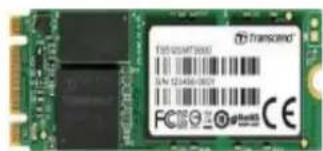
Figure 15: m.2 SSD
The following list summarizes the drives validated on the FWA-3260:
Please contact you Advantech representative for the most recent list of validated peripherals or if you would like to use modules not listed.
| Vendor | Vendor PN (Capacity) | Advantech PN |
| HDD Drive | ||
| WD | WD5000LUCT-63Y8HY0 500GB | |
| Intel | Intel SSD DC S3500 Series SSDSC2BB160G4 | |
| ADVANTECH | 820 Series 2.5” SATA III SSD 640G | SQF-25M5-60G-S8C |
| WD | SATA 2.5” HDD 1T (24x7) | 96ND1T-ST-WD5KE |
| m.2 SSD | ||
| ADATA | ADATA IM2S3138E-128GM-B | |
| Transcend | TS64GMTS400 TS64ZBTMM0000A | |
| Transcend | TS64GMTS800 TS64XBTMM0000A | |
| PLEXTOR | PLEXTOR PX-64G7Ge 64GB | 96FD42-N064-PLG |
| PLEXTOR | PLEXTOR PX-128G7Ge 128GB | 96FD42-N128-PLG |
| PLEXTOR | PLEXTOR PX-256G7Ne 256GB | 96FD80-N256-PLG |
| PLEXTOR | PLEXTOR PX-512G7Ne 512GB | 96FD80-N512-PLG |
Table 15: Validated SATA drives
2.4.6.3 Legacy Functions and IO
2.4.6.3.1 Serial Ports
The SoC integrates two 16C550 compliant UARTs which are mapped to the default resources:
| UART | Port | Resources | Implementation |
| 0 | COM1 | IO Range 0x3f8 -0x3ff,IRQ4 | Console port |
| 1 | COM2 | IO Range 0x2f7 – 0x2ff,IRQ3 | Interface to LCM |
Table 16: COM Ports
The SoC provide two high-speed serial communication ports (UARTs) with Tx/Rx only. The UARTs support legacy speeds up to 115.2K bps. Not support hardware flow control (CTS/RTS)
COM1 is used for console display, baud rate setting need consistent with external terminal. 115.2K is set in BIOS as default value.
2.4.6.3.2 SMBus
The PCH integrates two SMBus controllers. The first one is used as interface to external devices such as EEPROMs, the hardware monitor; the second controller is not used on the FWA-3260.

| SMBus | Adr, | Device | Function |
| 0 | 0x5A/5C | NCT7904D | Hardware monitor chip |
| 0 | 0xA0 | DIMM A0 SPD | SPD EEPROM |
| 0 | 0xA2 | DIMM A1 SPD | SPD EEPROM |
| 0 | 0xA4 | DIMM B0 SPD | SPD EEPROM |
| 0 | 0xA6 | DIMM B1 SPD | SPD EEPROM |
| 0 | 0xAC | 24C02 | System FRU EEPROM |
Table 17: SMBus Devices
Most of the SMBus devices are only accessed by BIOS at system start up to determine and set system configuration. Tampering with these devices may lead to system instability and malfunction.
Information on the hardware monitor and how to access it is provided in section 2.4.13. Information reg. the FRU EEPROM can be found in section 2.4.14.2.
2.4.7 Network interfaces (onboard)
The FWA-3260 supports a total of 6 network ports copper and 2 10G SFP+ port fiber on board.
There are 2 i210 GbE LAN device for management(locations F6), and 1 i350 for “traffic” ports(locations F7), the i210 is a single LAN chip and i350 GbE LAN device is a four port LAN chip, compact, low power components that offer a fully integrated Gigabit Ethernet Media Access Control (MAC) and Physical Layer (PHY) port.
The i210 LAN chip and i350 LAN chip are connected from integrated PCH PCIe port. The LAN chip can support PCIe Gen1 and 10/100/1000 Mb/s.
The X552 10G MAC integrated in Broadwell-DE SoC package, and it connect with external PHY CS4227 (10GbE SFP+ PHY) to support 2 SFP+ connector on board in front IO(locations F5).
2.4.8 PCIe Expansion
A std PCIex8 slot as add on card expansion module in rear paneCAC(locations R1). The expansion slot supports 1 PCIex8 gen.3 connectivity. (2 PCIex4 on request)
2.4.9 TPM Module
Infineon SLB9665TT2.0 FW5.00 TPM module is used in this design. The Infineon SLB SLB9665TT2.0 FW5.00 Trusted Platform Module (TPM) is an integrated circuit and software platform that provides computer manufacturers with the core components of a subsystem used to assure authenticity, integrity and confidentiality in e-commerce transactions and Internet communications. The SLB9665TT2.0 FW5.00 is a complete solution implementing version 2.0 of the Trusted Computing Group specifications (TCG), which is an industry group founded in 2003 by AMD, HP, IBM, Intel, Microsoft and now including more than 50 companies.
The board dimension of module is 20mmX20mm. A screw to secure the board in MB. Avoid system vibrations to cause module off.
2.4.10 LCD Module
Features
21 columns × 4 lines text display
128 × 32 dots graphic display
Text wrap, scroll and inverse capability
Built in characters plus 16 user defined characters
Communicate over RS232 interface
Baud rate speed selection between 9600 and 19200 bps
Programmable on/off and brightness of the LED backlight
Horizontal and vertical bar charts
32 bytes reserved non-volatile memory spaces for user settings
5 buttons keypad
Fit in a standard 3.5" floppy
2.4.11 Mass Storage
Up to four SATA devices and two m.2 SSD are supported by the FWA-3260. In the default configuration, two SATA 2.5" HDD devices are supported (location M1): an onboard m.2 socket with 22x42 or 60 or 80 type support (location M2) and another on board m.2 socket with 22x42 type support only(location M3).
The HDD power cable and SATA cable are supplied with the unit.
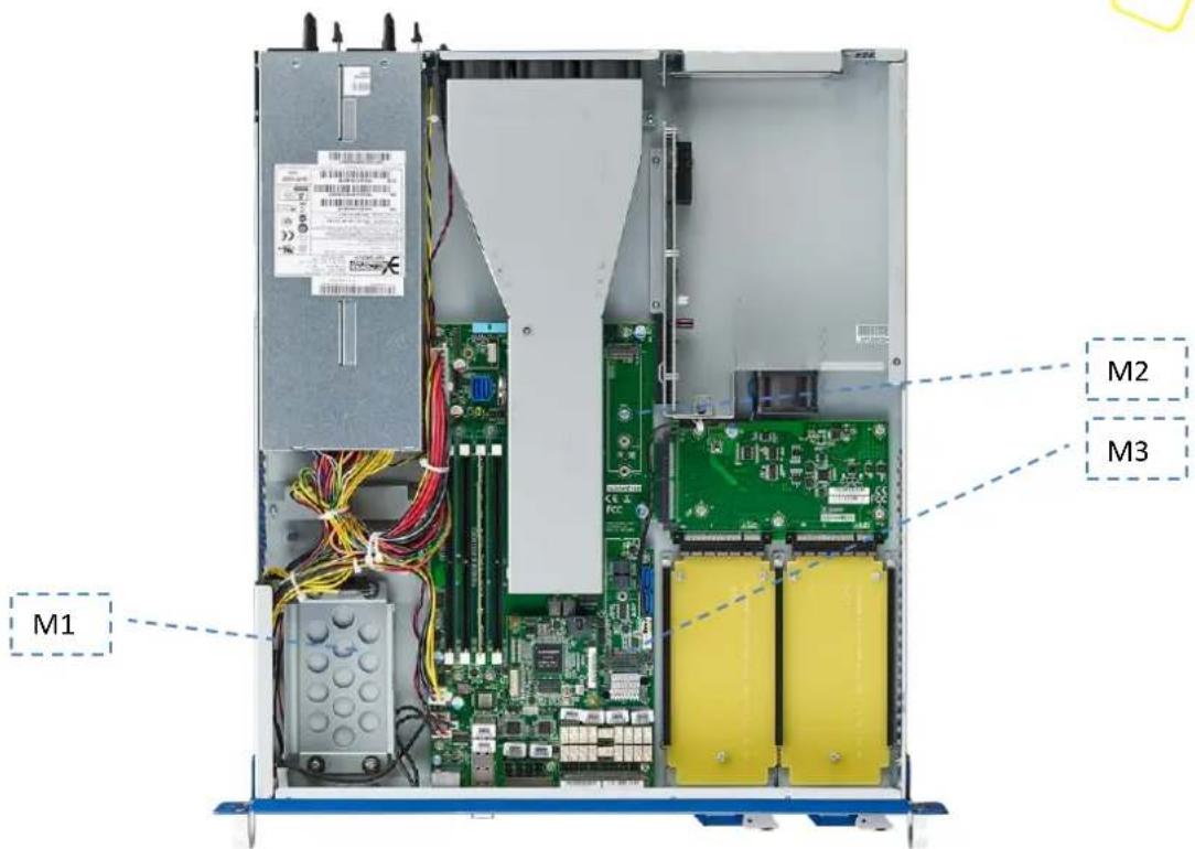
Figure 16: Mass storage components
2.4.12 BIOS
The FWA-3260's BIOS is based on AMI's APTIO BIOS and compliant to the UEFI, SMBIOS and ACPI specifications.
The BIOS performs probing, initialization and configuration of the FWA-3260 and initializes the OS boot process at the end of POST (Power On Self Test).
Regular BIOS output as well as the setup menu are displayed via the console port. Please refer to section 1.3.3 reg. the console connection process.
The BIOS Setup Menu is described in detail in section 3.2. BIOS Error Codes used during POST are described in appendix B.
Please note that the FWA-3260 does not have any onboard POST Code LEDs onboard. A special POST code adapter is required to retrieve BIOS error codes.
All BIOS configuration parameters bare stored in NVRAM, a dedicated section of the BIOS flash chip. Parameters are no longer stored in legacy CMOS RAM by the platform BIOS. I.e. BIOS configuration parameters will not be lost due to an empty battery.
2.4.12.1 Password protection
The BIOS supports and administrator password to restrict access to the BIOS setup menu to qualified and trusted personal, only.
2.4.12.2 BIOS defaults
The BIOS comes with a set of configuration parameters when shipped by Advantech referred to as “Optimized Defaults” or “factory defaults”. The user can change BIOS settings via the setup menu either temporarily or permanently by saving the changes as “User defaults”.
The BIOS loads Optimized Defaults by the option "Restore Defaults; and loads User defaults by the option "Restore User Defaults". If no User defaults have been defined, the BIOS will do nothing.
2.4.12.3 PCIe Tree
The BIOS also performs an enumeration of all PCIe resources, builds a bus/device map and assigns resources to the PCIe devices. Most OSs performs a reallocation of resources during start up. However, the PCIe bus/device map will not be changed by the OS. The table below gives an overview of the PCIe devices and their corresponding system function:
| PCIebus:dev:fun | PCIeVenID : DevID | Device | Description |
| 00:00:00 | 8086:6F00 | Host bridge | DMI2 x4 Link from Processor to PCH |
| 00:01:00 - 01 | 8086:6F02-6F03 | PCI ExpressRoot Port 1 | Intel PCIe Root Port 1 |
| 00:02:00 - 03 | 8086:6F04-6F07 | PCI ExpressRoot Port 2 | Intel PCIe Root Port 2 |
| 00:03:00 - 03 | 8086:6F08-6F0B | PCI ExpressRoot Port 3 | Intel PCIe Root Port 3 |
| 00:14:00 | 8086:8C31 | Intel USB xHCI | Intel USB3.0 Controller |
| 00:16:00 | 8086:8C3A | Intel® MEInterface #1 | Intel ME |
| 00:16:01 | 8086:8C3B | Intel® MEInterface #2 | Intel ME |
| 00:1C:00 | 8086:8C10 | Intel PCH PCIExpress* Port 1 | Intel PCH Root port1 |
| 00:1C:04 | 8086:8C18 | Intel PCH PCIExpress* Port 5 | Intel PCH Root port5 |
| 00:1C:05 | 8086:8C1A | Intel PCH PCIExpress* Port 6 | Intel PCH Root port6 |
| 00:1C:06 | 8086:8C1C | Intel PCH PCIExpress* Port 7 | Intel PCH Root port7 |
| 00:1D:00 | 8086::8C26 | Intel USB EHCI#1 | Intel EHCI controller |
| 00:1F:00 | 8086:8C54 | Intel LPC device | Intel LPC device |
| 00:1F:03 | 8086:8C22 | Intel SMBus | Intel SMBus controller |
| 00:1F:02 | 8086:8C06 | Intel SATA1 | Intel SATA controller |
| 00:1F:05 | 8086:8C08 | Intel SATA | Intel SATA controller |
| 02:00:00 - 03 | 8086:6F51-6F53 | Intel QuickData Technology | DMA Channel 0 to Channel 3 |
| 03:00:00 | 8086:15AC | Intel Lan controller | Intel BoradWell-DE LAN Controller |
| 05:00:00 | 8086:1521 | Intel I350 LAN | Onboard I350 LAN device #1 |
| 05:00:01 | 8086:1521 | Intel I350 LAN | Onboard I350 LAN device #2 |
| 05:00:02 | 8086:1521 | Intel I350 LAN | Onboard I350 LAN device #3 |
| 05:00:03 | 8086:1521 | Intel I350 LAN | Onboard I350 LAN device #4 |
| 06:00:00 | 8086:1533 | Intel I210 LAN | Onboard I350 LAN device #1 |
| 07:00:00 | 8086:1533 | Intel I210 LAN | Onboard I350 LAN device #2 |
| 08:00:00 | 1A03:1150 | Aspeed PCI Express Root Port | Aspeed PCIe Root Port |
| 09:00:00 | 1A03:2000 | Aspeed VGA | Onboard VGC |
Table 18: PCIe devices
2.4.13 Platform Management
A Nuvoton NCT7904 Hardware Monitor Chip (HWM) provides hardware monitoring capabilities on the FWA-3260. The HWM chip is connector to the PCH's SMBus. Standard software packages such as "lmsensors" can be used on the host to provide sensor information under Linux. Advantech provides the required patch that adds support for the HWM chip and a system specific configuration file.
Please contact your Advantech representative if you wish to receive the lmsensors patch or, in case you want to implement your own hardware monitoring solution, to obtain more details regarding the hardware implementation.
The HWM monitors all critical voltages on the FWA-3260:

natural_image
Abstract arrangement of yellow squares on white background (no text or symbols)| Pin No. | Pin Name | Function |
| 6 | HWM_VSEN6 | Monitor PSU +12V Power |
| 7 | HWM_VSEN7 | Monitor PSU 5V Power |
| 8 | HWM_VSEN8 | Monitor PSU 5V standby power |
| 9 | +VCORE | Monitor CPU Vcore Power |
| 11 | +VDDQ | Monitor DIMM Power |
| 13 | +1V05_PCH | Monitor PCH 1.05V power |
| 48 | VBAT | Monitor coin-battery Power |
Moreover, the following temperatures are supervised:
| Pin No. | Pin Name | Function |
| 2, 3 | HWM_DP1/2 | Monitor inlet Temperature |
| 5, 6 | HWM_DN1/2 | Monitor outlet Temperature |
The HWM also monitors the rear fans:
| Pin No. | Pin Name | Function |
| 29 | HWM_FANIN1 | Monitor FAN1 Speed |
| 31 | HWM_FANIN2 | Monitor FAN2 Speed |
| 33 | HWM_FANIN3 | Monitor FAN3 Speed |
| 35 | HWM_FANIN4 | Monitor FAN4 Speed |
In addition to the HWM, the Xeon D CPU features integrated temperature sensors (1 per core) that are supported by the module of lmsensors:
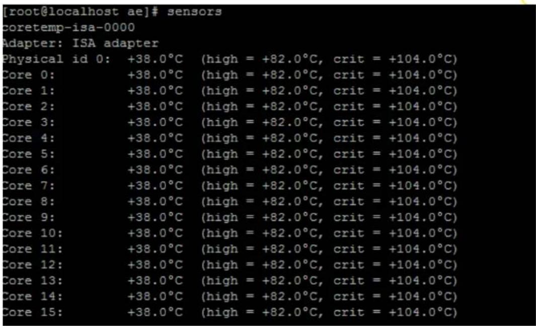
Figure 19: Display of CPU temperature
The diagram below shows the location of the various temperature sensors:
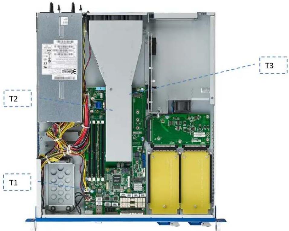
Figure 17: Thermal Sensor Locations
| Sensor | Description |
| T1 | Air Inlet Sensor |
| T2 | CPU Temperature Sensors (integrated into SoC) |
| T3 | Air Outlet Sensor |
Table 20: Thermal Sensors
2.4.14 Power Supplies
The FWA-3260 supports a single AC and redundant PSU wide range PSU located at position Rx. Technical specification for the power supply can be found in appendix C.
2.4.14.1 Product Labelling
The FWA-3260 contains a number of labels that help to identify the product as well as the MAC addresses used by the system. The type label is placed on the bottom side of the unit and other labels can be found inside the unit.
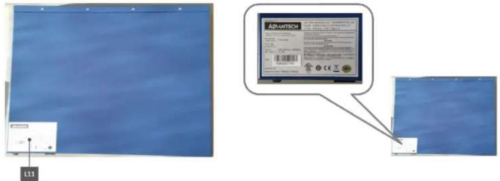
Figure 18: Type Label (bottom)

natural_image
Abstract arrangement of yellow squares on white background (no text or symbols)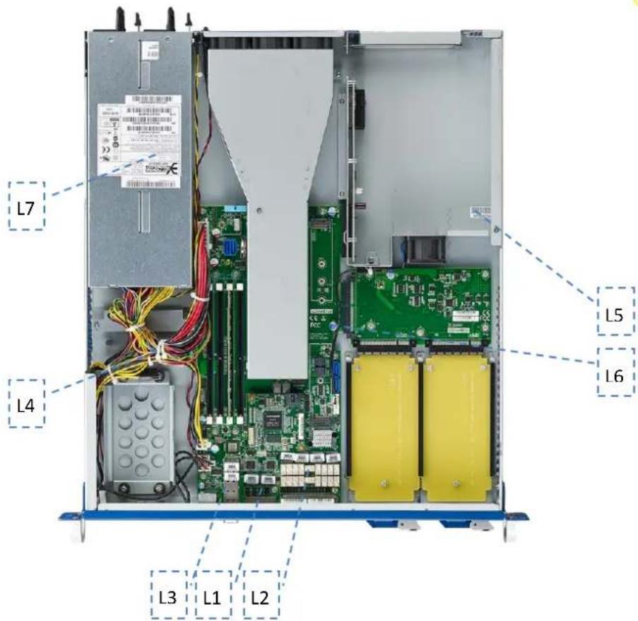
Figure 19: Product Labels (internal)
| Label | Description |
| L1 | MAC Address for Management Port 0/1 |
| L2 | MAC Address for Traffic Port 1~4 |
| L3 | MAC Address for Traffic Port 5/6 |
| L4 | Motherboard Serial Number |
| L5 | System Serial Number |
| L6 | CE/FCC/RoHS/WEEE labels (on PCB) |
| L7 | PSU labels (PSU specific) |
Table 21: Product Labels

natural_image
Abstract arrangement of yellow squares on white background (no text or symbols)2.4.14.2 Electronic label: FRU EEPROM
The FWA-3260 supports an onboard FRU EEPROM which can be accessed via SMBus 0 using afru. The table below shows the FRU EEPROM format:
| DMI Table | Field in DMI Table | Field in System FRU | Parameter in afru_mfg |
| Type 1System Information | Manufacturer | Product Manufacturer | PM |
| Product Name | Product Name | PN | |
| Version | Product Version | PV | |
| Serial Number | Product Serial | PS | |
| SKU Number | Product Part Number | PPN | |
| Type 2Base Board Information | Manufacturer | Board Mfg | BM |
| Product Name | Board Product | BP | |
| Version | Product Version | PV | |
| Serial Number | Board Serial | BS | |
| Type 3Chassis Information | Version | Chassis Part Number | CPN |
| Serial Number | Chassis Serial | CS |
Table 22: FRU Data Synced to the DMI Tables
Alternatively, FRU information is also embedded in DMI Tables 1/2/3 and can be displayed with DMI parsing tools like dmidecode.
For a detailed description of the FRUs functionality and the related software API, please refer to the Advantech_Afru_Utility_User_Guide_Rev0_1. ( Please contact your Advantech representative to get the doc)
2.5 Advanced Platform features
2.5.1 Intrusion detection
The FWA-3260 does not support intrusion detection by default. This feature has been reserved in the motherboard design, though, and can be enabled at system level via customization. Please contact your Advantech representative should you be interested in this option.
2.5.2 Watchdog
The FWA-3260 provides a programmable watchdog that may be used to reset the system in case it bites due to malfunctioning application software to restore the unit to a known good state. The watchdog is based on H/W monitor 7904D timer. The watchdog timer is supported under Linux via a kernel driver. Please refer to Linux documentation in details.
2.5.3 LAN Bypass
For a detailed description of the LAN Bypass functionality and the related software API, please refer to the Advanced LAN Bypass User's Manual.
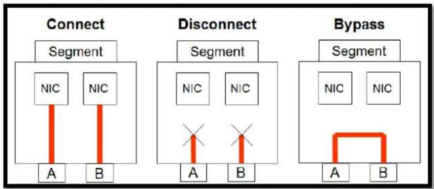
LAN bypass allows automated or manual control of the connectivity between two LAN ports grouped into a bypass segment and the host:
flowchart
graph TD
    subgraph Connect
        A1["Segment"] --> A2["A"]
        A2 --> B1["B"]
        B1 --> C1["NIC"]
        A2 --> D1["NIC"]
    end
    subgraph Disconnect
        E1["Segment"] --> E2["A"]
        E2 --> F1["B"]
        F1 --> G1["NIC"]
        E2 --> H1["X"]
        F1 --> I1["X"]
        G1 --> J1["X"]
    end
    subgraph Bypass
        K1["Segment"] --> K2["A"]
        K2 --> L1["B"]
        L1 --> M1["NIC"]
        K2 --> N1["NIC"]
    end
Figure 20: Connectivity options of LAN ports in a bypass segment
In “connect” mode, the ports on a segment are connected to the host via NICs. Traffic will enter and leave the ports just like on a regular NIC.
In "disconnect" mode, the ports are disconnected from the host and from each other. No traffic can flow through the ports
In “bypass” mode, the two ports are disconnected from the host, but connected to each other. Traffic entering the system on one port will be sent out on the other port and vice versa.
"Bypass mode" is used to allow traffic to flow through the system when the system is in a non operational state such as loss of power or in case the application is unresponsive. Application health is monitored by a configurable watchdog.
"Disconnect" mode is typically used to block any traffic until the system has fully started up and the application SW is in a well defined state allowing to handle traffic properly.
Connectivity can be auto controlled by a number of system events:

natural_image
Abstract arrangement of yellow squares on white background (no text or symbols)● Power Up
Host system is turned on / powers up (DC on)
● Power Down
Host system is turned off / powers down (DC off)
● Power Reset
Host system is reset or rebooted
● Watchdog Start
LAN bypass watchdog is started or strobed for the first time
● Watchdog Timeout
LAN bypass watchdog timed out
● External Trigger
Global Watchdog Trigger input (dedicated GPIO pin)
In addition to the event driven model, it is also possible to set the connectivity for a bypass segment via the SW API.
2.5.3.1 LAN Bypass Segments
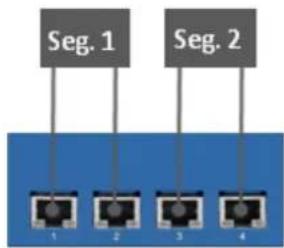
The FWA-3260 supports four onboard traffic ports which are grouped into 2 bypass segments as shown below:
flowchart
graph TD
    A["Seg. 1"] --> B["Port 1"]
    C["Seg. 2"] --> D["Port 2"]
    E["Seg. 2"] --> F["Port 3"]
    G["Seg. 2"] --> H["Port 4"]
Figure 21: Onboard LAN ports and bypass segments
2.5.3.2 Bypass Watchdog Support
Each bypass segment is support by an independent watchdog timer. The timer basis is set to 100ms. Watchdog timeout periods can be set between 100ms and 6553.5 seconds (about 109 minutes).
The FWA-3260 also supports a global watchdog trigger which allows multiple bypass segments to be controlled at the same time. The global watchdog signal is connected between the two onboard bypass segments and also to the PCIe extension connector (for future use).
2.5.3.3 LED Behaviour
Advantech Advanced LAN bypass uses a LED to show the state of a bypass segment. Usually the bypass LED is implemented as a dual colour LED combined with a regular LAN port LED. The table below shows the status of the bypass LED, only. For a complete description of port LEDs please refer to appendix A.3.2).
| State | LED Status |
| CONNECT | Off |
| BYPASS | Solid Amber |
| DISCONNECT | Blinking Amber (1Hz) |
Table 23: Bypass States and LED behaviour

natural_image
Abstract arrangement of yellow squares on white background (no text or symbols)2.6 Available Accessories and Related Products
2.6.1 Accessories
The following accessories are available for ordering. Please contact your Advantech representative for a list of available and supported peripherals such as memory modules, hard disks and solid state drives
| Model Name | Configurations |
| 1702002600 | Power cable 3P 180 cm, USA |
| 1702002605 | Power cable 3P 180 cm, Europe |
| 1702031801 | Power cable 3P 180 cm, UK |
| 1700000237 | Power cable 3P 180 cm, JP |
| 9680006903 | Repon 20" traditional slide rail screws type |
| 9680016887 | Repon 20" slide rail tool-less type |
| 9680016903 | Repon 22" traditional slide rail screws type |
| 9680016888 | Repon 22" slide rail tool-less type |
Table 24: Accessories
3. CONFIGURATION AND SERVICE
3.1 Jumper Settings
There are no jumpers on the FWA-3260 intended for customer use.
3.2 BIOS Setup Menu
This section describes the FWA-3260's UEFI BIOS based on AMI's APTIO BIOS.
Users can modify BIOS settings and control the special features of the FWA-3260 using the BIOS setup menu.
Please note that Advantech supports shipping the FWA-3260 with custom BIOS defaults to simplify the deployment and integration for our customers. Please contact your Advantech representative if you want to receive more information regarding this service.
The BIOS Setup Menu can be entered via the BIOS POST screen displayed on the console interface:
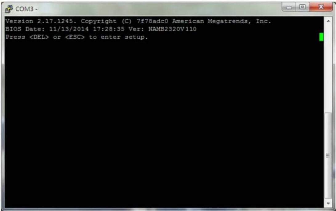
Figure22: BIOS POST screen (example)
BIOS Setup can be entered by hitting or
The BIOS setup menu screens have a few main elements as shown below. The menu bar displays the selectable menu pages as tabs. The parameter window displays and allows configuration of the settings available in a given menu page or a submenu thereof. Auxiliary text providing information about the selected setup item is displayed in the top right corner.

![Aptio Setup Utility - Copyright (C) 2014 American Megatrends, Inc. Main Advanced IntelRCSetup Save & Exit Menu Bar BIOS Information BIOS Vendor American Megatrends Core Version 5.009 Compliancy UEFI 2.9; PI 1.2 BIOS Version 2320 V6.42 Build Date and Time 10/24/2014 17:28:57 Memory Information Total Memory 8192 MB (DDR3) Settings Window System Language [English] System Date [Tue 11/25/2014] System Time [17:54:21] Access Level Administrator Choose the system default language Auxiliary Text ><: Select Screen v: Select Item Enter: Select +/-: Ch F1: General Help F2: F3: Optimized Defaults F4: Save & Exit ESC: Exit Hot Key Description Version 2.17.1245. Copyright (C) 2014 American Megatrends, Inc.](/content/2026/05/818837/images/c3ea29ba7738d6655be43cbcb2c2f46eec9e0725a440d09e7a804b4ebc6e6373.jpg)
Figure 23: BIOS Setup Screen Organization
3.2.1 Main Setup Menu
If security protection has been enabled previously (see chapter 3.2.4), you will be prompted for the BIOS password upon entering the BIOS Setup. After a successful check or if password protection has not been enabled, users will see the Main Setup screen shown below. Users can always return to the Main setup screen by selecting the Main tab.
![Aptio Setup Utility - Copyright (C) 2016 American Megatrends, Inc. Main Platform Hardware Post & Boot Security Save & Exit BIOS Information BIOS Vendor American Megatrends Core Version 5.011 0.20 x64 Compliancy UEFI 2.4; PI 1.3 Project Version FWA-3260 3260000V104 Build Date and Time 01/22/2016 14:02:10 NVRAM Version 03.00 System Language [English] System Date [Tue 02/16/2016] System Time [14:38:38] Access Level Administrator Choose the system default language <<: Select Screen : Select Item Enter: Select +/-: Change Opt. F1: General Help F2: Previous Values F3: Optimized Defaults F4: Save & Exit ESC: Exit](/content/2026/05/818837/images/7e0ba02987cb5e5a6da65113c5c99074549fd53a42566c057067033cf6b5f6a4.jpg)
Figure 24: BIOS Setup Main screen
The main setup page displays system a summary of system and BIOS configuration and status information. The fields on this page are read-only except for the System Date and Time setting.
| Group | Setup item | Access / Options | Description |
| BIOS Information | BIOS Vendor | Display only | American Megatrends |
| Core Version | Display only | Current AMI BIOS core version in use | |
| Compliancy | Display only | UEFI Spec revision that the BIOS complies to | |
| Project Version | Display only | Advantech BIOS Version infoEX: mmmm Vx.yzmmmm : model nameX : major versionYz: minor version | |
| Build Date & Time | Display only | Shows BIOS build date and time | |
| NVRAM Version | Display only | Shows current NVRAM ver. | |
| System Language | Display only | Selects the Setup Menu Language. Only English is supported on the FWA-3260. | |
| System Date | MM/DD/YY | Displays and sets the system date as used by the BIOS | |
| System Time | HH:MM:SS | Displays and sets the system time as used by the BIOS | |
| Access Level | Display only | Shows the user privilege level according to the security settings. If password protection has not been enabled, this will default to “Administrator” |
Table 25: BIOS Setup: Main Menu
3.2.1.1 Setting System Time and Date
Use this option to change the system time and date. Highlight System Time or System Date using the
Please not that system time and date are set during manufacturing process according to factory's local time zone. You may need to update system time to reflect the desired time zone when you receive the unit.

3.2.2 Platform Setup Menu
Select the Platform tab from the FWA-3260 setup screen to enter the Platform Setup screen. Users can select any of the items in the left frame of the screen, such as the Trusted Computing Configuration, to go to the sub menu for that item. Users can display an Platform BIOS Setup option by highlighting it using the
The Platform BIOS Setup screen is shown below. The sub menus are described on the following pages.
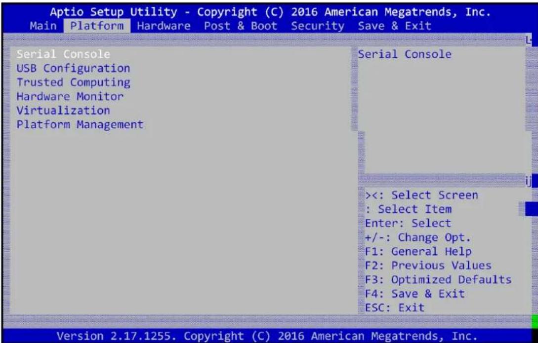
Figure25: Platform Setup Main screen
3.2.2.1 Serial Port Console Redirection
This sub menu allows you to change the settings used for the serial console.
Note that the serial console is always using COM1 which is connected to the front panel.
![Aptio Setup Utility - Copyright (C) 2016 American Megatrends, Inc. Platform Console Redirection [Enabled] Serial Console Port [COM0] Serial Console Speed [115200] Data Bits [8] Stop Bits [1] Parity [None] Terminal Type [ANSI] VT-UTF8 Combo Key Sup [Enabled] Recorder Mode [Disabled] Resolution 100x31 [Disabled] Legacy OS Redirection [80x24] Putty KeyPad [VT100] Redirection After BIO [Always Enable] Serial Port for Out-of-Band Management/ Windows Emergency Management Services (EMS) Console Redirection [Disabled] Console Redirection Settings Console Redirection <<: Select Screen : Select Item Enter: Select +/-: Change Opt. F1: General Help F2: Previous Values F3: Optimized Defaults F4: Save & Exit ESC: Exit Version 2.17.1255. Copyright (C) 2016 American Megatrends, Inc.](/content/2026/05/818837/images/d69316e1d03f369953a69f5d01cfb1f184d04fbbfdb4a19518b8124322b44860.jpg)
Figure 26: Platform Setup: Console Redirection Menu
3.2.2.1.1 COM1 Console Redirection Settings
The settings for COM1 console can be accessed in this menu.
This sub menu allows you to change the settings used for the serial console. For example, users can define the terminal type, bits per second, data bits, parity, stop bits and others.
| Setup item | Access / Options | Description |
| Terminal Type | ANSI / VT100 / VT100+ / VT-UTF8 | Select the target terminal emulation type:- ANSI to use the Extended ASCII Character Set.- VT100 to use the ASCII Character set.- VT100+ to add color and function key support.- VT-UTF8 to use UTF8 encoding to map Unicode characters into one or more bytes. |
| Serial Console Speed | 9600 / 19200 / 38400 / 57600 / 115200 | Defines the baud rate. |
| Data Bits | 7 / 8 | Defines number of data bits in a character. |
| Parity | None / Even / Odd / Mark / Space | Defines the parity scheme used. |
| Stop Bits | 1 / 2 | Defines number of stop bits in a character. |
| Flow Control | None / Xon/Xoff | Defines the flow control scheme. |
| VT-UF8 Combo Key | Disabled / Enabled | Enables VT-UTF8 Combination Key Support for ANSI / VT100 terminals |
| Recorder Mode | Disabled / Enabled | When Enabled the data displayed on a terminal will be captured and sent as text messages to a remote server. |
| Resolution 100x31 | Disabled / Enabled | Enables or disables extended terminal resolution |
| Legacy OS redirection | 80x24 / 80x 25 | When using Legacy OS, this item specifies the Number of Rows and Columns supported |
| PuTTY Keypad | VT100 /. LINUX / XTERMR6 / SCO / ESCN / VT400 | Select Function Key and Key Pad Emulation on PuTTY. |
| Redirection after BIOS | Always Enable / BootLoader | This defines how long console redirection will be active: “BootLoader” means that legacy console redirection is disabled before booting into a Legacy OS. “Always Enable” means Legacy console Redirection is enabled permanently. |
Table 26: Platform Setup: COM1 Console Redirection Menu Items
3.2.2.2 USB Configuration
This sub menu allows you to change the settings used for USB and to get an overview of the USB devices detected by the BIOS.
![Aptio Setup Utility - Copyright (C) 2016 American Megatrends, Inc. Platform USB Support [Enabled] Legacy USB Support [Enabled] EHCI Hand-off [Disabled] Port 60/64 Emulation [Enabled] USB hardware delays a USB transfer time-out [20 sec] Device reset time-out [20 sec] Device power-up delay [Auto] Device power-up delay 5 USB Support Parameters <<: Select Screen : Select Item Enter: Select +/-: Change Opt. F1: General Help F2: Previous Values F3: Optimized Defaults F4: Save & Exit ESC: Exit Version 2.17.1255. Copyright (C) 2016 American Megatrends, Inc.](/content/2026/05/818837/images/8638bfd96221b81228e455132d7d0addd54f55dd7f5306ae5dc7e17cd1e3271b.jpg)
Figure 27: Platform Setup: USB Configuration Menu
| Group | Setup item | Access / Options | Description |
| None | USB Support | EnabledDisabled | Enables or disables the support for USB. If disabled, the USB EHCl controller will not be initialized by the BIOS. |
| Legacy USB Support | AutoEnabledDisabled | Enables legacy support over USB to support Keyboard and Mouse | |
| EHCI Hand-Off | EnabledDisabled | Controls the hand off of EHCl ownership from BIOS to OS at boot time. | |
| USB hardware delay | USB transfer time-out | 1sec / 5sec / 10sec / 20sec | The time-out value for Control, Bulk, and Interrupt transfers. |
| Device Reset time-out | 10sec / 20sec / 30sec / 40sec | Time Out for a device to Reset | |
| Device power-up delay | AutoManual | Maximum time the device will take before it properly reports itself to the Host Controller. | |
| Device power-up delay | 5 |
Table 27: USB Configuration Menu
3.2.2.3 Trusted Computing
Please note that Trusted Computing support is disabled by default in the factory defaults to save system boot time. If disabled, the Trusted Computing Menu will not display any status information.
![Aptio Setup Utility - Copyright (C) 2016 American Megatrends, Inc. Platform Configuration Device Select [Auto] Current Status Information TPM 1.2 will restrict support to TPM 1.2 devices, TPM 2.0 will restrict support to TPM 2.0 devices, Auto will support both with the default set to TPM 2.0 devices if not found, TPM 1.2 devices will be <<: Select Screen : Select Item Enter: Select +/-: Change Opt. F1: General Help F2: Previous Values F3: Optimized Defaults F4: Save & Exit ESC: Exit Version 2.17.1255. Copyright (C) 2016 American Megatrends, Inc.](/content/2026/05/818837/images/2620f0539f0b4ea2baef4a7902bd5e26f8ae890f5ff830d43feebbaf877e7195.jpg)
Figure 28: Platform Setup: Trusted Computing
| Group | Setup item | Access / Options | Description |
| Configuration | Security Device Sup | AutoTPM1.2TPM2.0 | Auto will support both or set the support for the TPM 1.2 or TPM2.0. |
| Current Status information | Support Turned Off | Display Only | Is displayed when TPM support is disabled |
| TPM State | Display Only | Shows TPM Enablement Status | |
| TPM Active State | Display Only | Shows TPM Activation Status | |
| TPM Owner | Display Only | Shows Current TPM Owner |
Table 28: Trusted Computing Menu
3.2.2.3.1 Trusted Computing with TPM module installed
When system with TPM2.0 module installed, and the BIOS will auto detect it and the related setting will be shown in the BIOS setup menu as below.
![Aptio Setup Utility - Copyright (C) 2016 American Megatrends, Inc. Platform TPM20 Device Found Security Device Sup [Enable] TPM State [Enabled] Pending operation [None] Platform Hierarchy [Enabled] Storage Hierarchy [Enabled] Endorsement Hierarc [Enabled] HashPolicy [Sha-1] TPM 20 InterfaceTyp [TIS] Device Select [Auto] Enables or Disables BIOS support for security device. O.S. will not show Security Device. TCG EFI protocol and INT1A interface will not be available. <<: Select Screen : Select Item Enter: Select +/-: Change Opt. F1: General Help F2: Previous Values F3: Optimized Defaults F4: Save & Exit ESC: Exit Version 2.17.1255. Copyright (C) 2016 American Megatrends, Inc.](/content/2026/05/818837/images/82b56f10069b91845587ee6465ab3a6f1dcdb7d082e454ecb1ce0ac3d505abca.jpg)
Figure 29: Platform Setup: Trusted Computing with TPM2.0
| Group | Setup item | Access / Options | Description |
| TPM20 Device Found | Security Device Sup | Enable Disable | BIOS support for security device. O.S. will not show Security Device. TCG EFI protocol and INT1A interface will not be available. |
| TPM State | Enable Disable | Enable/Disable Security Device. NOTE: Your Computer will reboot during restart in order to change State of the Device. | |
| Pending operation | None | Schedule an Operation for the Security Device. NOTE: Your Computer will reboot during restart in order to change State of Security Device. | |
| Platform Hierarchy | Enable Disable | Enable or Disable Platform Hierarchy | |
| Storage Hierarchy | Enable Disable | Enable or Disable Storage Hierarchy | |
| Endorsement Hierarchy | Enable | Enable or Disable Endorsement Hierarchy | |
| Disable | |||
| Hashpolicy | Sha-1 | Select the Hash policyto use. SHA-2 is most secure but might not be supported by all Operating Systems | |
| TPM 20 InterfaceTyp | Display only (TIS) | ||
| Device Select | Auto | Auto will support both or set the support for the TPM 1.2 or TPM2.0. |
Table 29: Trusted Computing Menu with TPM2.0
3.2.2.4 H/W Monitor
This sub menu allows you to see all the H/W monitor items detected by the BIOS, for well know the current system health status.
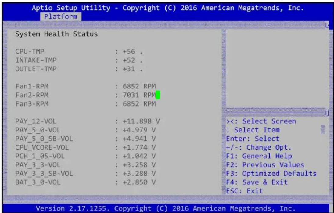
Figure 30: Platform Setup: H/W monitor
3.2.2.5 Virtualization
This sub menu allows you to change the settings used for Virtualization function.
Intel® Virtualization Technology for Directed I/O (VT-d). Thus, BIOS handle virtual functions exposed by PCIe devices in case SR-IOV is supported, otherwise PCIe devices will be assigned to virtual machines in pass-through mode. This applies for all PCIe devices.
![Aptio Setup Utility - Copyright (C) 2016 American Megatrends, Inc. Platform Intel Virtualization [Enabled] Intel VT-d [Enabled] Enables the Vanderpool Technology, takes effect after reboot. <<: Select Screen : Select Item Enter: Select +/-: Change Opt. F1: General Help F2: Previous Values F3: Optimized Defaults F4: Save & Exit ESC: Exit Version 2.17.1255. Copyright (C) 2016 American Megatrends, Inc.](/content/2026/05/818837/images/7a8c36c3190935ff230c8a321d27b932d12a46a9af47c817e8b2eabb2e9b350c.jpg)
Figure 31: Platform Setup: Virtualization
| Group | Setup item | Access / Options | Description |
| None | Intel Virtualization | Enable Disable | Enable/Disable Intel Virtualization Technology, take effect after reboot |
| Intel VT-d | Enable Disable | Enable/disable Intel Virtualization Technology for Directed I/O (VT-d) by reporting the I/O device | |
| IOAT | Hidden (Enable) | This item will be hidden and enable it by default setting for get better performance |
Table 30: Virtualization Menu
3.2.2.6 Platform Management
This sub menu allows you to change the settings used for related CPU utilization setting.
The default configuration for CPU was optimized setting for getting better performance for networking, so it is not recommend to change it.
![Aptio Setup Utility - Copyright (C) 2016 American Megatrends, Inc. Platform EIST [Disabled] P-state coordination [HW_ALL] CPU C3 report [Disabled] CPU C6 report [Enabled] Package C State limit C0/C1 state] Energy Performance Tu [Enabled] WHEA Support [Disabled] Bmc self test log System Event Log When enabled, OS sets CPU frequency according load. When disabled, CPU frequency is set at max non-turbo. <<: Select Screen : Select Item Enter: Select +/-: Change Opt. F1: General Help F2: Previous Values F3: Optimized Defaults F4: Save & Exit ESC: Exit Version 2.17.1255. Copyright (C) 2016 American Megatrends, Inc.](/content/2026/05/818837/images/830bf5be6ac255731b33fb62f38a1f96c5692e0740db605c1fd688503a73add1.jpg)
Figure 32: Platform Setup: Platform Management
| Group | Setup item | Access / Options | Description |
| None | EIST | Enable Disable | Enable or disable BIOS support for Enhanced Intel SpeedStep Technology, When enabled, OS sets CPU frequency according load. When disabled, CPU frequency is set at max non-turbo. |
| P-state coordination | HW_ALL | HW_ALL (hardware) coordination is recommended over SW_ALL and SW_ANY (software coordination). | |
| CPU C3 report | Enable Disable | Enable/Disable CPU C3(ACPI C2) report to OS. Recommended to be disabled. | |
| CPU C6 report | Enable Disable | Enable/Disable CPU C6(ACPI C2) report to OS Recommended to be enabled. | |
| Package C State limit | C0/C1 state C2 state C6(non Retention) state C6(Retention) state | Package C State limit. The "waking-up time" will be longer if Package C state limit setting is deep C state support. | |
| Energy | Enable | Selects whether BIOS or Operating System | |
| Performance Tu | Disable | chooses energy performance bias tuning. | |
| WHEA Support | Enable Disable | Enable or disable the WHEA support | |
| BMC Self test log | Erase Log | Yes, On every reset | Erase Log Options |
| When log is full | Clear Log | Select the action to be taken when log is full | |
| System event log | SEL Components | Enable Disable | Change this to enable or disable all features of System Event Logging during boot. |
| Erase SEL | No | Choose options for erasing SEL. | |
| When SEL is Full | Do Nothing | Choose options for reactions to a full SEL. | |
| Log EFI Status Codes | Error code | Disable the logging of EFI Status Codes or log only error code or only progress code or both |
Table 31: Platform Management Menu
3.2.3 Hardware
This sub menu allows you to change the settings of the Intel chipset. Please note that “chipset” is a legacy term and the related functionality is split over the CPU and PCH portions of the SoC. Similarly, the terms “South Bridge” and “North Bridge” are legacy terms and do not represent the silicon implementation any more. However, those terms are kept consistent with previous products to allow users to navigate more easily.
The sub menus are described on the following pages.
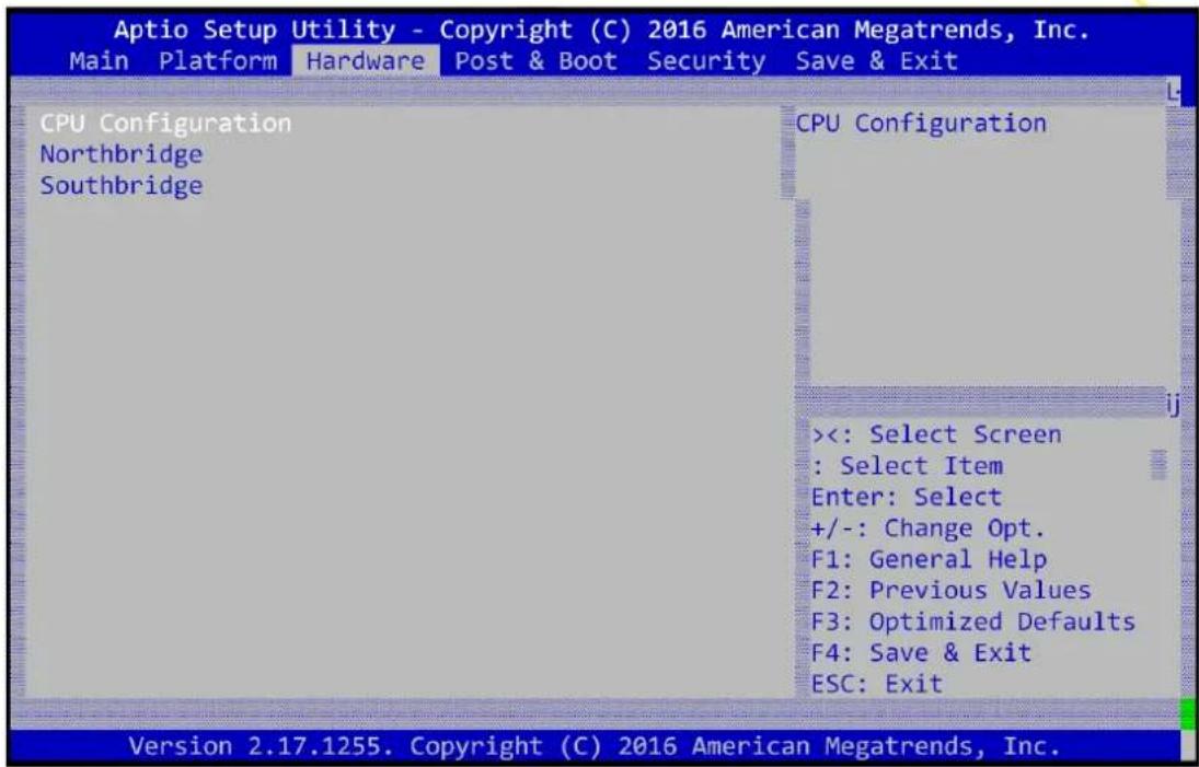
Figure 33: Hardware Configuration Menu
3.2.3.1 Hardware Setup: CPU Configuration
This menu supports configuration of the Xeon D CPU.
![Aptio Setup Utility - Copyright (C) 2016 American Megatrends, Inc. Hardware Socket 0 CPU Information Hyper-Threading [Enabled] Execute Disable Bit [Enabled] Hardware Prefetcher [Enabled] Adjacent Cache Prefet [Enabled] DCU Streamer Prefetch [Enabled] DCU IP Prefetcher [Enabled] Socket 0 CPU Information <<: Select Screen : Select Item Enter: Select +/-: Change Opt. F1: General Help F2: Previous Values F3: Optimized Defaults F4: Save & Exit ESC: Exit Version 2.17.1255. Copyright (C) 2016 American Megatrends, Inc.](/content/2026/05/818837/images/662aa3236af95c99f80ead5b42b9ac3da3d7c45e06e57c4d1818c255c634f892.jpg)

natural_image
Abstract arrangement of yellow squares and a gray rectangle on white background (no text or symbols)Figure 34: Chipset: Processor Configuration Menu
| Group | Setup item | Access / Options | Description |
| Socket0 CPU information | CPU signature | Display only | Displays information on the processor installed |
| Microcode Patch | |||
| CPU Frequency | |||
| Processor Cores | |||
| Intel VT-x Technology | |||
| L1 code Cache | |||
| L2 Cache | |||
| L3 Cache | |||
| None | Hyper-threading | Enable Disable | Enables Hyper Threading (Software Method to enable/disable logical processor threads. |
| Execute Disable Bit | Enable Disable | Execute Disable Bit allows the processor to classify areas in memory where application code can be executed and cannot preventing certain classes of malicious buffer overflow attacks when combined with a supporting operating system. | |
| Hardware Prefetcher | Enable Disable | Enable or disable Hardware Prefetcher feature.= MLC Streamer Prefetcher (MSR 1A4h Bit[0]) | |
| Adjacent Cache Line Prefetch | Enable Disable | Enable or disable Adjacent Cache Prefetch feature.= MLC Spatial Prefetcher (MSR 1A4h Bit[1]) | |
| DCU Streamer Prefetch | Enable Disable | Enable or disable DCU Streamer Prefetcher feature.DCU streamer prefetcher is an L1 data cache prefetcher (MSR 1A4h [2]). | |
| DCU IP Prefetcher | Enable Disable | Enable or disable DCU IP Prefetcher feature.DCU IP prefetcher is an L1 data cache prefetcher (MSR 1A4h [3]). |
Table 32: Processor Configuration Menu
3.2.3.2 Hardware Setup: North Bridge Configuration
This menu allows the configuration of the memory controller and related features of the SoC.
![Aptio Setup Utility - Copyright (C) 2016 American Megatrends, Inc. Hardware DIMM Information Channel Interleaving [Auto] Rank Interleaving [Auto] Patrol Scrub [Enabled] Demand Scrub [Enabled] Data Scrambling [Auto] PCI Express Ports Configuration QPI Configuration DIMM Information <<: Select Screen : Select Item Enter: Select +/-: Change Opt. F1: General Help F2: Previous Values F3: Optimized Defaults F4: Save & Exit ESC: Exit Version 2.17.1255. Copyright (C) 2016 American Megatrends, Inc.](/content/2026/05/818837/images/ba1755e4d48ef1e69c62cba5898a7d14f48eda9195a0a4b5ab55984be1150781.jpg)
Figure 35: NorthBridge Configuration Menu
| Group | Setup item | Access / Options | Description |
| DIMM Information | Total Memory | Display only | Displays information on the processor installed |
| Memory Frequency | |||
| Channel Interleaving | Auto[1-way Interleave][2-way Interleave][3-way Interleave][4-way Interleave] | Select Channel Interleaving setting | |
| Rank Interleaving | Auto[1-way Interleave][2-way Interleave][4-way Interleave][8-way Interleave] | Select Rank Interleaving setting | |
| Patrol Scrub Enable | Enabled | Select to enable / disable Patrol Scrub Support | |
| Demand Scrub Enable | Enabled | Select to enable / disable Demand Scrub Support | |
| Data Scrambling | Auto | Select to auto to enable the Scrambler |
Table 33: Northbridge Configuration Menu
3.2.3.3 PCI Express Port Configuration
This sub-menu contains settings for the PCIe subsystem. Some menu items are referred to as "PCI" settings. Although the FWA-3260 does not implement a PCI bus, these settings still apply to the platform as PCIe is using the same configuration mechanism as PCI.
![Aptio Setup Utility - Copyright (C) 2016 American Megatrends, Inc. Hardware Subtractive Decode [Enabled] PCIe Hot Plug [Disabled] Above 4G Decoding [Disabled] SR-IOV Support [Disabled] IOH 0 PCIe port Bifurcation Control PORT 1A Link Speed [Auto] PORT 1B Link Speed [Auto] IOU1 - PCIe Port [Auto] IOU3 - PCIe Port [Auto] PCI Express Subtractive Decode Enable/Disable. <<: Select Screen : Select Item Enter: Select +/-: Change Opt. F1: General Help F2: Previous Values F3: Optimized Defaults F4: Save & Exit ESC: Exit Version 2.17.1255. Copyright (C) 2016 American Megatrends, Inc.](/content/2026/05/818837/images/4737b9c5d45a96e0b5b973b3490aaeffff8e6837faf733720f044e834208119b.jpg)
Figure 36: Hardware Setup: PCI Subsystem
| Group | Setup item | Access / Options | Description |
| None | Subtractive Decode | EnabledDisable | PCI Express Subtractive DecodeEnable/disable |
| PCIe Hot Plug | EnabledDisable | Enable PCIe hot plug | |
| Above 4G Decoding | EnabledDisable | Enables or Disables 64bit capable Devices to be Mapped above 4GB in the Address | |
| Space. | |||
| SR-IOV Support | EnabledDisable | Enable this for support Dingle Root IO virtualization | |
| Above 4G Decoding | Enabled / Disabled | Enables or Disables 64bit capable Devices to be Mapped above 4GB in the Address Space. | |
| IOH 0 PCIe port Bifurcation Control | PORT 1A Link Speed | GEN1GEN2GEN3AUTO | Change PCI Express Devices Settings. |
| PORT 3A Link Speed | GEN1GEN2GEN3AUTO | Change PCI Express Devices Settings. | |
| IOU1 - PCIe Port | x4x4x4x4x4x4x8x8x4x4x8x8x16Auto | Select PCIe port bifurcation | |
| IOU3 - PCIe Port | x4x4x4x4x4x4x8x8x4x4x8x8x16Auto | Select PCIe port bifurcation |
Table 34: Hardware Setup: PCI Subsystem Menu Items
3.2.3.4 QPI Configuration
This sub-menu contains settings for the QPI configuration.
![Aptio Setup Utility - Copyright (C) 2016 American Megatrends, Inc. Hardware Isoc Mode [Disabled] Link Speed Mode [Fast] Link Frequency Select [Auto] Link L0p Enable [Enable] Link L1 Enable [Enable] Isoc: Disable,Enable <<: Select Screen : Select Item Enter: Select +/-: Change Opt. F1: General Help F2: Previous Values F3: Optimized Defaults F4: Save & Exit ESC: Exit Version 2.17.1255. Copyright (C) 2016 American Megatrends, Inc.](/content/2026/05/818837/images/1dfa92983c2b823d65f222e974b0a142fedcf160c30fd829d42b780ea714d013.jpg)
Figure 37: Hardware Setup: QPI configuration
| Group | Setup item | Access / Options | Description |
| None | Isoc | EnabledDisable | Enable/disable ISOC |
| Link Speed Mode | FastSlow | Select QPI link speed as either the POR speed (Fast) or default speed (slow) | |
| Link Frequency Select | Auto6.4 GB/s8.0 GB/s9.6 GB/sAuto Limited | Allows for Selecting the QPI link frequency | |
| Link0p Enable | EnabledDisabled | Enable/disable Link0 | |
| Link1p Enable | EnabledDisabled | Enable/disable Link1 |
Table 35: Hardware Setup: QPI configuration Menu Items
3.2.3.5 Hardware Setup: South Bridge Configuration
This menu contains settings for the South Bridge for related SATA and USB and ACPI setting etc.
![Aptio Setup Utility - Copyright (C) 2016 American Megatrends, Inc. Hardware SATA Configuration USB Configuration ACPI Settings Runtime Error Logging PCH Compatibility RID [Disabled] SMBus Controller [Enabled] PCH state after G3 [Power On] SATA Configuration <<: Select Screen : Select Item Enter: Select +/-: Change Opt. F1: General Help F2: Previous Values F3: Optimized Defaults F4: Save & Exit ESC: Exit Version 2.17.1255. Copyright (C) 2016 American Megatrends, Inc.](/content/2026/05/818837/images/257a5cae49d5587423ce69234d0cb39f7230aabd4c4fa91df49ae7a0af118b07.jpg)
Figure 38: Hardware Setup: South Bridge configuration
| Group | Setup item | Access / Options | Description |
| SATA Configuration | N/A | Select sub-menu. | |
| USB Configuration | N/A | Select sub-menu. | |
| ACPI Settings | N/A | Select sub-menu. | |
| Runtime Error Logging | N/A | Select sub-menu. | |
| PCH Compatibility RID | Enable/Disable | Enable or Disable PCH's CCRID | |
| SMBus Controller | Enable/Disable | Enable or Disable SMBus CDevice | |
| PCH state after G3 | Power on | Select S0/S5 for ACPI state after a G3 |
Table 36: Hardware Setup: South Bridge configuration Menu Items
3.2.3.5.1 South Bridge Configuration: SATA Configuration
![Aptio Setup Utility - Copyright (C) 2016 American Megatrends, Inc. Hardware SATA Port 0 [Not Installed] SATA Port 1 [Not Installed] SATA Port 2 [Not Installed] SATA Port 3 [Not Installed] SATA Port 4 [Not Installed] SATA Port 5 [Not Installed] SATA Mode [AHCI] SATA Controller [Enabled] Hot Plug #Port 0 [Disabled] Hot Plug #Port 1 [Disabled] Hot Plug #Port 2 [Disabled] Hot Plug #Port 3 [Disabled] Hot Plug #Port 4 [Disabled] Hot Plug #Port 5 [Disabled] This will configure SATA as IDE ,RAID or AHCI. <<: Select Screen : Select Item Enter: Select +/-: Change Opt. F1: General Help F2: Previous Values F3: Optimized Defaults F4: Save & Exit ESC: Exit Version 2.17.1255. Copyright (C) 2016 American Megatrends, Inc.](/content/2026/05/818837/images/3a259124e23cd74e2c3e96bb7664287c156a211bc767aef70867308c9e9ddcb9.jpg)
Figure 39: Hardware Setup: SATA configuration
| Feature | Default | Description |
| SATA Port0 | Display only | Show current SATA devices in use on the FWA-3260 |
| SATA Port1 | Display only | |
| SATA Port2 | Display only | |
| SATA Port3 | Display only | |
| SATA Port4 | Display only | |
| SATA Port5 | Display only | |
| SATA Mode | AHCI Mode | (1) IDE Mode. (2) AHCI Mode. (3) RAID Mode. |
| SATA Controller | Enabled | To enable the SATA controller |
Table 37: Hardware Setup: SATA configuration Menu Items
3.2.3.6 USB Configuration
This menu contains settings for the USB configuration.
![Aptio Setup Utility - Copyright (C) 2016 American Megatrends, Inc. Hardware xHCI Mode [Auto] Mode of operation of USB Port #0 Disable [Enabled] YxHCI controller. USB Port #1 Disable [Enabled] Y USB Port #2 Disable [Enabled] Y USB Port #3 Disable [Enabled] Y USB Port #4 Disable [En xHCI Mode L USB Port #5 Disable [En Smart Auto USB Port #6 Disable [En Auto USB Port #7 Disable [En Enabled USB Port #8 Disable [En Disabled USB Port #9 Disable [En Manual USB Port #10 Disable [En USB Port #11 Disable [Enab USB Port #12 Disable [Enabled] Y+/-: Change Opt. USB Port #13 Disable [Enabled] YF1: General Help YF2: Previous Values USB 3.0 Port #0 Disab [Enabled] F3: Optimized Defaults USB 3.0 Port #1 Disab [Enabled] F4: Save & Exit USB 3.0 Port #2 Disab [Enabled] ESC: Exit Version 2.17.1255. Copyright (C) 2016 American Megatrends, Inc.](/content/2026/05/818837/images/0707420131c00521a1f76320bfc1c858f5fdcaa1781c93bf675b296121c7c758.jpg)
Figure 40: Hardware Setup: USB configuration
| Group | Setup item | Access / Options | Description |
| None | xHCI Mode | Smart AutoAutoEnabledDisabledManual | To set up the mode of operation of xHCI controller |
Table 38: Hardware Setup: USB configuration Menu Items
3.2.3.7 ACPI Setting
This menu contains settings for the ACPI configuration.
![Aptio Setup Utility - Copyright (C) 2016 American Megatrends, Inc. Hardware Enable ACPI Auto Conf [Disabled] Enable Hibernation [Disabled] ACPI Sleep State [Suspend Disabled] Lock Legacy Resources [Disabled] Enables or Disables BIOS ACPI Auto Configuration. <<: Select Screen : Select Item Enter: Select +/-: Change Opt. F1: General Help F2: Previous Values F3: Optimized Defaults F4: Save & Exit ESC: Exit Version 2.17.1255. Copyright (C) 2016 American Megatrends, Inc.](/content/2026/05/818837/images/6702718674db21102d71261591dec21fa8565366df008d686498f15a919adebd.jpg)
Figure 41: Hardware Setup: ACPI configuration
| Group | Setup item | Access / Options | Description |
| None | Enable ACPI Auto Configuration | EnabledDisabled | Enable or disable BIOS ACPI auto configuration |
| Enable Hibernation | EnabledDisabled | Enable the system ability to hibernate (OS/S4 sleep state), this option may be not effective with some O.S | |
| ACPI Sleep State | SuspendDisabledS1 (CPU Stop Clock) | Select the highest ACPI sleep state the system will enter when the SUSPEND button is pressed. | |
| Lock Legacy Resources | EnabledDisabled | Enable lock of legacy resources |
Table 39: Hardware Setup: ACPI configuration Menu Items
3.2.3.8 Runtime Error logging
This sub-menu contains settings for the Runtime error logging configuration.
![Aptio Setup Utility - Copyright (C) 2016 American Megatrends, Inc. Hardware System Errors [Disabled] PCI-Ex Error Enable [Enabled] System Errors Disabled Enabled Auto System Error enabling and logging setup option. <<: Select Screen : Select Item Enter: Select +/-: Change Opt. F1: General Help F2: Previous Values F3: Optimized Defaults F4: Save & Exit ESC: Exit Version 2.17.1255. Copyright (C) 2016 American Megatrends, Inc.](/content/2026/05/818837/images/8682ce295e3e3e9ad7abcdcbe813937756a9c91ab9ed2e7c7f31f2161df45698.jpg)
Figure 42: Hardware Setup: Runtime Error logging configuration
| Group | Setup item | Access / Options | Description |
| None | System Errors | EnabledDisabledAuto | System error enabling and logging setup option |
| PCI-Ex Error Enable | EnabledDisabled | Enable or Disable PCI-Ex Error |
Table 40: Hardware Setup: Runtime Error logging Menu Items
3.2.4 Server Mgmt
The Server Mgmt menu supports configuring BMC related features such as OS Watchdog Timer, etc.
![Aptio Setup Utility - Copyright (C) 2016 American Megatrends, Inc. Main Platform Hardware Server Mgmt Post & Boot Security Save & Exit BMC Self Test Status PASSED OS Watchdog Timer [Disabled] OS Wtd Timer Timeout [10 minutes] OS Wtd Timer Policy [Reset] If enabled, starts a BIOS timer which can only be shut off by Management Software after the OS loads. Helps determine that the OS successfully loaded or follows the OS Boot Watchdog Timer ><: Select Screen : Select Item Enter: Select +/-: Change Opt. F1: General Help F2: Previous Values F3: Optimized Defaults F4: Save & Exit ESC: Exit Version 2.17.1255. Copyright (C) 2016 American Megatrends, Inc.](/content/2026/05/818837/images/112f758d4b545bbeec8f0b5e145e8434836537bfe5cff843f70642338ee75236.jpg)
Figure 43: Server Mgmt configuration
| Group | Setup item | Access / Options | Description |
| None | BMC Self Test Status | Display only (Passed) | BMC self test status indication during power on process |
| OS Watchdog Timer | Enable Disable | If enabled, starts a BIOS timer which can only be shut off by Management Software after the OS loads.Helps determine that the OS successfully loaded or follows the OS Boot Watchdog Timer | |
| OS Wtd Timer Timeout | 5 minutes10 minutes15 minutes20 minutes | Configure the length of the OS Boot Watchdog Timer. Not available if OS Boot Watchdog Timer is disabled. | |
| OS Wtd Timer Policy | Do Nothing Reset Power Down | Configure how the system should respond if the OS Boot Watchdog Timer expires. Not available if OS Boot Watchdog Timer is disabled. |
Table 41: Server Mgmt configuration Menu Items
3.2.5 Security Setup
"Administrator Password" allows users to configure the system so that a password after being installed is required each time the system boots, and/or an attempt is made to enter the Setup program.
Note:
If set the "Password Check" is [Setup], then this only limits access to Setup and is only asked for when entering Setup.
If set the "Password Check" is [Always], then this is a power on password and must be entered to boot or enter Setup. In Setup the User will have Administrator rights.
◆ The password length must be in the following range:
■ Minimum length: 3
■ Maximum length: 20
3.2.6 POST & Boot Menu
Users can configure the system boot priority settings via the boot page. The default setting of boot priority of boot option #1 is "UEFI: Built-in EFI Shell"; Users can define the boot priorities based on the application.
![Aptio Setup Utility - Copyright (C) 2016 American Megatrends, Inc. Main Platform Hardware Post & Boot Security Save & Exit Setup Prompt Timeout Bootup NumLock State Quiet Boot Network Stack Boot Option Priorities Boot Option #1 CSM16 Parameters CSM Parameters 1 [On] [Disabled] [Disabled] [UEFI: Built-in EFI ...] Number of seconds to wait for setup activation key. 65535(0xFFFF) means indefinite waiting. <<: Select Screen : Select Item Enter: Select +/-: Change Opt. F1: General Help F2: Previous Values F3: Optimized Defaults F4: Save & Exit ESC: Exit Version 2.17.1255. Copyright (C) 2016 American Megatrends, Inc.](/content/2026/05/818837/images/9404bc21304db35921d46efdd6fbf7551f16b2b4067fc7d6c47f56017dffc758.jpg)
Figure 44 Boot Configuration
| Feature | Default | Description |
| Setup Prompt Timeout | 1 | Number of seconds to wait for setup activation key. |
| Bootup NumLock State | On | Select the keyboard NumLock state. |
| Quiet Boot | Disabled | Enables or disables Quiet Boot option. |
| Network Stack | Disabled | Enables or disables boot via Network (PXE) |
| Boot Option Priority | User Defined | Sets the system boot order. |
| CSM16 Parameters | Option ROM Messages | Force BIOSKeep Current |
| CSM Parameters | CSM Support | Enable the CSM support |
Table 42 Boot Configuration
3.2.6.1 Compatibility Support Module (CSM) Configuration
This submenu allows users to configure the support for legacy BIOS mechanisms and option ROMs.
![Aptio Setup Utility - Copyright (C) 2016 American Megatrends, Inc. Post & Boot CSM Support [Enabled] Boot option filter [UEFI and Legacy] Network [Do not launch] Storage [Legacy] Video [Legacy] Other PCI devices [UEFI] Enable/Disable CSM Support. CSM Support L- Disabled Enabled <<: Select Screen : Select Item Enter: Select +/-: Change Opt. F1: General Help F2: Previous Values F3: Optimized Defaults F4: Save & Exit ESC: Exit Version 2.17.1255. Copyright (C) 2016 American Megatrends, Inc.](/content/2026/05/818837/images/d4a6c21462764f3664d152a141fea3cc3c79ae0ffeb17f4fcd395b39adb45937.jpg)
Figure 45: Post & Boot Setup: CSM Configuration Menu
| Group | Setup item | Access / Options | Description |
| None | CSM Support | EnabledDisabled | Enables or disables the Compatibility Support Module. |
| Boot option filter | UEFI and LegacyLegacy OnlyUEFI Only | This item allows to control the execution of legacy and UEFI compliant Option ROMs | |
| Network | Do not launchUEFILegacy | This item allows a more granular control of OptionROM execution depending of the type of extension device. | |
| Storage | |||
| Video | |||
| Other PCI device ROM |
Table 43: CSM Configuration Menu
3.2.7 Save & Exit Menu
The FWA-3260 BIOS allows users to store BIOS configuration results as "User Defaults." Users can select "Save as User Defaults" to record all changes which had been made in previous pages as the default setting for further use.
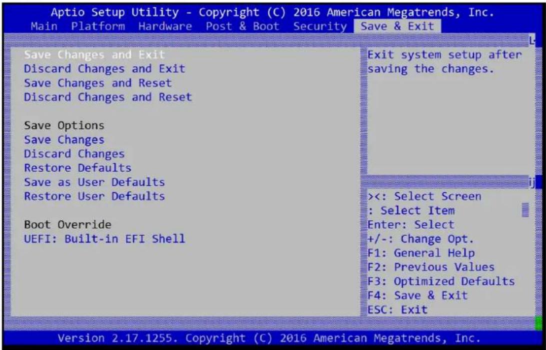
Figure 46: Save & Exit Menu
| Group | Setup item | Description |
| None | Save Changes and Exit | Exit setup after saving the changes. Does not update User defaults. |
| Discard Changes and Exit | Exit setup without saving any changes. | |
| Save Changes and Reset | Reset system after saving the changes. Does not update User Defaults. | |
| Discard Changes and Reset | Reset system without saving the changes. | |
| Save Options | Save Changes | Save Changes made so far to any of the setup options. |
| Discard Changes | Discard Changes made so far to any of the setup options. | |
| Restore Defaults | Restores the BIOS factory defaults to all the setup options. | |
| Save as User Defaults | Saves the Current BIOS Settings as User Defaults. | |
| Restore User Defaults | Restores the User defaults to all the setup options. | |
| Boot Override | UEFI: < boot device> | This option allows you to override the specified boot order and use a different boot device for the next boot. |
Table 44: Save & Exit Menu Options
3.3 Installing Components
Please make sure you follow the safety guidelines presented in section1.1 when making changes to the hardware.
3.3.1 Removing the top cover
You need:
- a PH2 screw driver
The top cover is secured by a total of 7 screws, 2 each on the left, rear and right side:
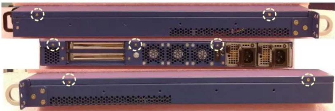
natural_image
Three views of a server rack with ventilation grilles and internal components (no visible text or labels)Figure 47: Top cover screw locations (left/rear/right)
To remove the top cover, remove these screws using a PH1 screw driver. Be sure to keep the screws in a safe place for top cover re-installation.
After that, slide the top cover backwards until the front flange of the top cover disengages with the unit's face plate:
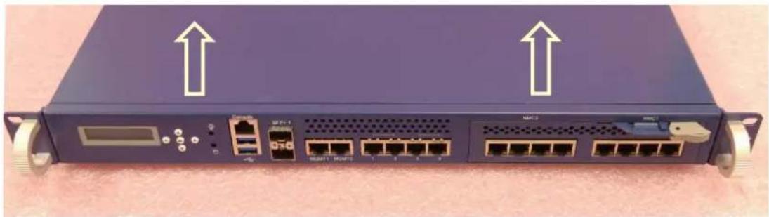
natural_image
Front view of a network switch device with ports and connectors, no visible text or symbols on the device body
Figure 48: Slide Top Cover back
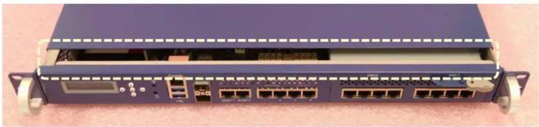
natural_image
Front view of a network switch device with multiple Ethernet ports and a central display unit (no visible text or labels)Figure 49: Top Cover Flange Disengagement
Now lift off and remove the top cover.
3.3.2 Reinstalling the top cover
You need:
- a PH2 screw driver
To re-install the top cover slide it onto the unit from the top with the top cover flange facing the unit's face plate. Keep a gap of about an inch between the front plate and the flange.
After that, slide the top cover forward until the flange is fully seated underneath the face plate.
Now insert the screws in the 7 locations shown above. Tighten each screw only lightly then move on to the next screw. After all screws have been inserted, tighten them.
3.3.3 Disk Installation
3.3.3.1 2.5" HDD drive
You need:
- a PH2 screw driver
- a standard 2.5" SATA HDD
- the HDD screw kit (included in the unit)
- the HDD carrier plate (included in the unit)
- the SATA cable (included in the unit)
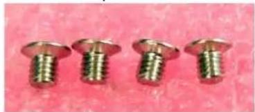
natural_image
Four metallic screw fasteners arranged horizontally on a pink textured background (no text or symbols visible)Figure 50: Screws for HDD mounting
After removing the top cover, follow the instructions below for 2.5" disk installation:
1) Remove the plastic bag that protects the HDD carrier plate.

2) The HDD carrier plate has three holes on each side to accommodate different HDD vendor's mounting hole locations. Each of the holes provides a dampening rubber to reduce disk vibration.
Do not remove the rubbers as this may lead to performance degradation or even malfunction.
Insert the HDD drive from the top into the carrier plate. Align the HDD's mounting threads with 2 of the 2 holes on each side of the carrier plate. The holes to use may vary from disk vendor to disk vendor. For some vendors, all four holes may align.
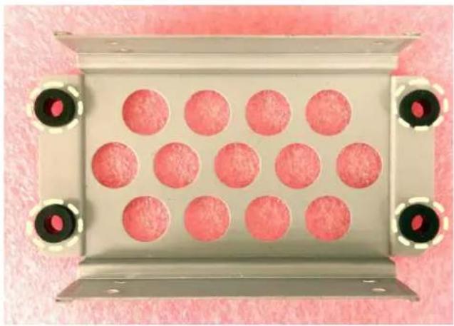
natural_image
Metallic tray with 12 pink circular indentations, mounted on a silver base with black circular connectors (no text or symbols visible)Figure 51: HDD Carrier plate dampeners
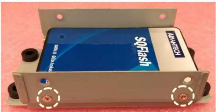
Figure 52: Carrier plate and HDD alignment
3) Insert the screws supplied as part of the HDD kit into the holes and HDD threads. Make a few turns on each screw only using a PH2 screw driver until the threads start to engage. Then move on to the next screw. When all screws have been inserted, fasten the screws tightly.
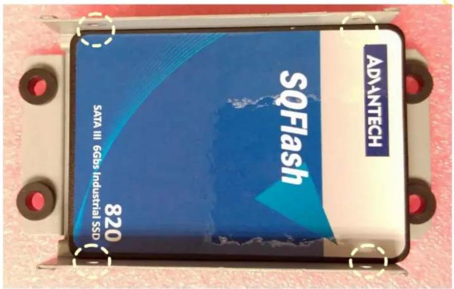
Figure 53: Screw insertion and fastening
4) Move the carrier plate into the system location M1 and align the carrier plate's mounting holes with the standoffs in the chassis.
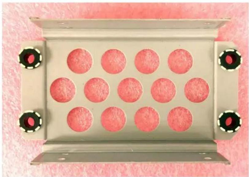
natural_image
Metallic tray with 12 circular red components and black screw holes, placed on a pink textured surface (no text or symbols visible)Figure 54: HDD Carrier plate screw locations
5) Insert the carrier plate mounting screws and start to fix them from the front side (i.e. the side facing the FWA-3260 motherboard). Securely tighten the screws using a PH2 screw driver after having inserted all four screws.

natural_image
Abstract arrangement of yellow squares on white background (no text or symbols)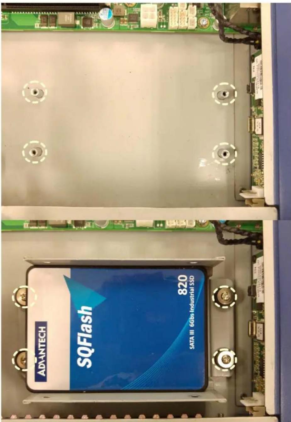
Figure 55: Insertion of the carrier into the chassis
6) Connect the SATA cable delivered with the unit to the disk as well as the mother board connector. Please make yourself aware of the keying mechanism in the SATA connector before inserting the cable.

natural_image
Abstract arrangement of yellow squares on white background (no text or symbols)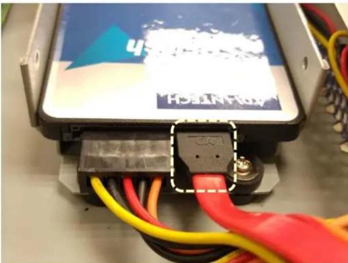
natural_image
Close-up of a black electronic device with red and yellow wires connected to its base, no visible text or symbols on the device itself.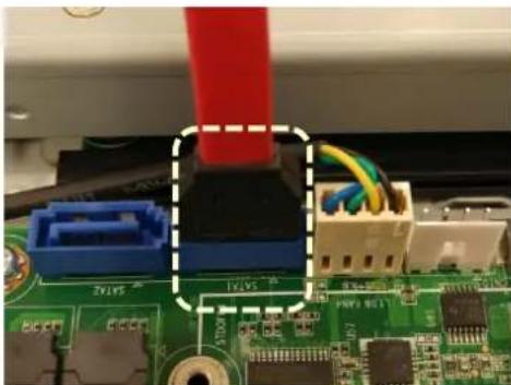
natural_image
Close-up of electronic circuit board with connectors and components (no readable text or symbols)Figure 56: SATA cabling
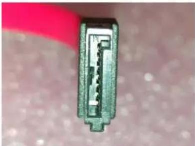
natural_image
Close-up of a metallic connector with internal structure, partially covered by a red band (no visible text or symbols)Figure 57: SATA Connector keying
7) Connect the HDD power cable to the disk. Please make yourself aware of the keying mechanism in the power connector before inserting the cable.

natural_image
Abstract pattern of overlapping yellow squares on white background (no text or symbols)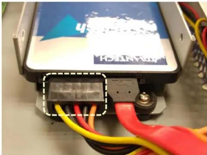
natural_image
Close-up of a black electrical component with red, yellow, and blue wires connected to a control panel (no visible text or symbols)Figure 58: HDD Power cable
3.3.3.2 M.2 SSD
You need:
- a PH1 screw driver
- a standard M.2 SSD
- the M.2 SSD mounting screw (included in the unit)
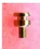
Figure 59: M.2 SSD mounting screw

An M.2 SSD compliant SSD can be installed at location M3:
1) Make sure the M.2 SSD disk is compliant with the socket and that the mechanical keys match
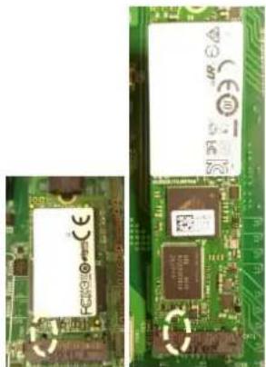
natural_image
Close-up of two green printed circuit boards showing electronic components and traces (no readable text or symbols)Figure 60: m.2 SSD key alignment
2) Insert the M.2 SSD module in the connector under an angle of around 45^ . The gold contacts of the module will almost disappear in the connector when the module is fully seated.
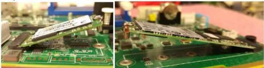
natural_image
Close-up of a green printed circuit board with visible traces and components (no text or symbols)Figure 61: M.2 SSD angled insertion
3) Push down the module softly until it is in horizontal position. If the module is correctly seated, the module's right hand mount hole will align with the threaded standoff in the FWA-3260 motherboard. Insert the M.2 SSD mounting screw and tighten it.
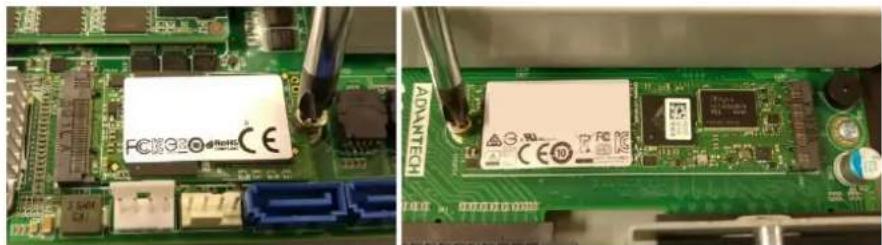
natural_image
Close-up of a green printed circuit board with visible components and soldering tools (no readable text or symbols)Figure 62: M.2 SSD mounting
3.3.4 Memory Installation
After removing the top cover, follow the instructions below for DIMM installation:
1) Double check that the DIMMs to be installed match the requirements of section 2.4.5.
2) Open the white latches on the left and right sides of the DIMMs by turning it outwards as indicated by the arrows below.
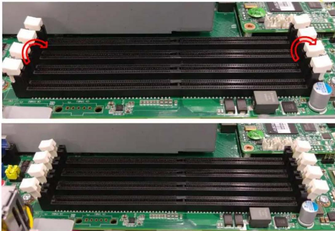
natural_image
Two views of a green circuit board with black plastic components and connectors, showing internal structure and mounting points (no text or symbols visible)Figure 63: Opening DIMM latches
3) Select DIMM orientation so that the keys in the DIMM module and socket match.
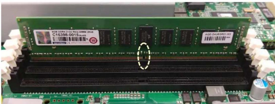
Figure 64: DIMM key alignment
4) Insert the DIMM from the top using the guide rails on the left and right of the DIMM sockets.
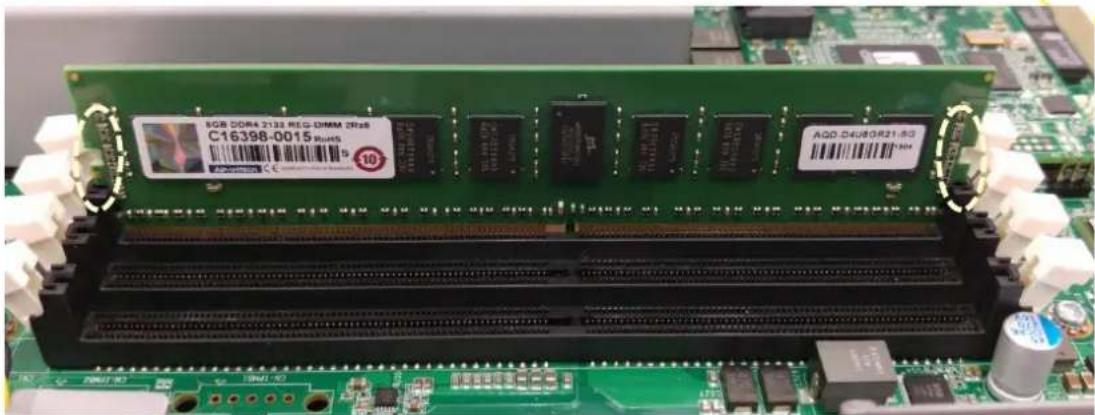
Figure 65: DIMM insertion into slide rails
5) Put your thumbs near the right and left end of the DIMM and press down the DIMM evenly until the white latches fully close with a click.
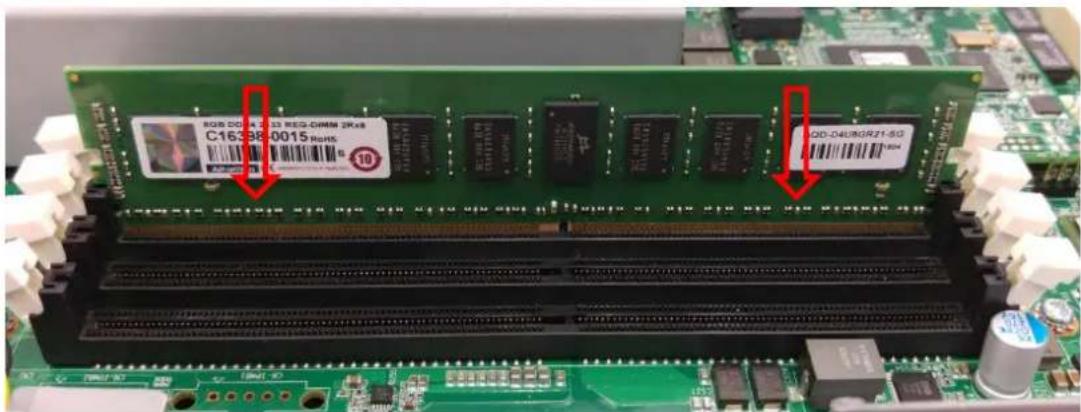
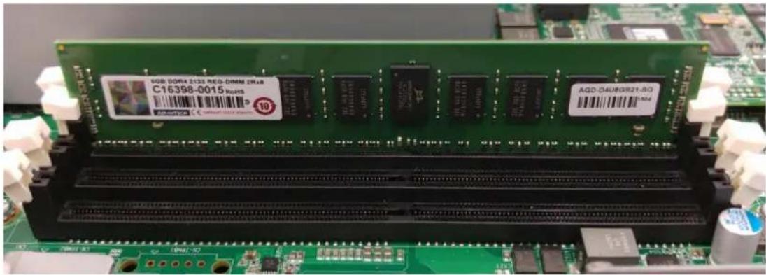
Figure 66: Seating the DIMM in the socket
6) In case you want to install another DIMM, repeat steps 1) to 5) accordingly.
3.4 Firmware Upgrades
3.4.1 BIOS
The BIOS can be upgraded using “flashrom” under Linux. flashrom Version 0.9.7-r1855 or newer is required. Or go for IPMI command with HPM.1 to upgrade the BIOS (SKUs depends, only FWA-3260A with LOM support this features, please refer to the file of
"Advantech_FWA_3260_Advanced_Platform_Management_Users_Guide_Rev0_1" in details
flashrom is available via www.flasrom.org or as part of all major Linux distributions.
Documentation on flashrom can also be found there.
Start flashrom with the following parameters to update the BIOS on the FWA-3260:
-w (BIOS Name) -p internal: laptop=this_is_not_laptop
[root@FWA-3231 home]# flashrom -w 2320V044.bin -p internal:laptop=this_is_not_laptop
flashrom v0.9.8-r1888 on Linux 2.6.32-431.el6.x86_64 (x86_64)
flashrom is free software, get the source code at http://www.flashrom.org

Calibrating delay loop... OK.
Found chipset "Intel Avoton/Rangeley".
This chipset is marked as untested. If you are using an up-to-date version of flashrom *and* were (not) able to successfully update your firmware with it, then please email a report to flashrom@flashrom.org including a verbose (-V) log.
Thank you!
Enabling flash write... Warning: SPI Configuration Lockdown activated.
OK.
Found Winbond flash chip "W25Q64.V" (8192 kB, SPI) mapped at physical address 0 x00000000ff800000.
Reading old flash chip contents... done.
Erasing and writing flash chip... Erase/write done.
Verifying flash... VERIFIED.
[root@FWA-3231 home]#
3.4.2 LAN Bypass
LAN Bypass Firmware can be upgraded via the LAN Bypass Software. Please refer to the Advanced LAN Bypass User's Manual for details.
3.5 Replacing FRUs
Please make sure you follow the safety guidelines presented in section1.1 when making changes to the hardware.
For instruction on how to remove and install the top cover of the unit please refer to section 3.3.
3.5.1 Disk drives

3.5.1.1 2.5" HDD
You need:
- a PH2 screw driver
a standard 2.5" SATA HDDTo remove the HDD, proceed in the reverse of the installation procedure in section 3.3.3.1:
5) Detach the HDD power and SATA cables
6) Remove the four screws on the corners of the HDD carrier plate and remove the HDD carrier plate from the system
7) Remove the HDD mounting screws and extract the HDD from the carrier plate.
8) Install a new HDD by following the instructions in section 3.3.3.1.
3.5.1.2 M.2 SSD
You need:
- a PH1 screw driver
- a standard m.2 SSD
To remove a m.2 SSD proceed in the reverse of the installation procedure in section 3.3.3.2:
1) Remove the m.2 mounting screw. Please be sure to hold the screw as the spring mechanism in the m.2 connector will flip the m.2 module upwards once the screw is lose.
2) Extract the m.2 module
Install a new SSD following the mounting instructions of the same section.
3.5.2 CMOS Battery
You need:
- A BR2032 battery
Warning!
There is the danger of explosion if the battery is replaced incorrectly. Replace the battery only with the same or equivalent type specified above.
Dispose of used batteries according to the manufacturer's instructions.
To replace the RTC's battery located at B1, pull the spring clip securing the battery forward with your finger tip. Please handle with care and do not bend the spring clip. Then extract the battery vertically.

natural_image
Abstract graphic with yellow overlapping squares and a gray document icon (no text or symbols)


natural_image
Abstract arrangement of yellow squares on white background (no text or symbols)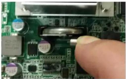
natural_image
Close-up of a green printed circuit board with electronic components and a finger pointing to a component (no visible text or symbols)Figure 67: Unlocking the battery
Keeping the spring clip pulled towards you, insert the replacement battery.
Please make sure you insert the battery in correct polarity with the positive pole facing the front panel and the negative pole facing the CPU heatsink. Trying to insert the battery with incorrect orientation/polarity will damage the battery holder. Additional security risks apply as stated above.
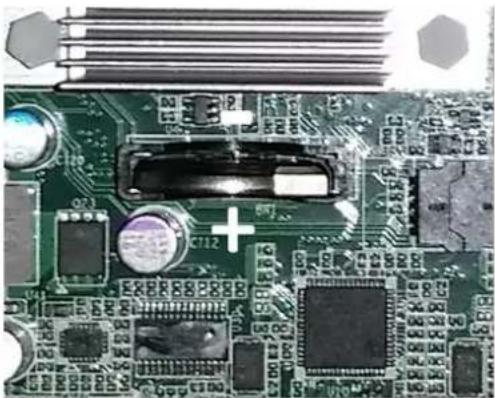
natural_image
Close-up of a green printed circuit board with electronic components and connectors (no readable text or symbols)Figure 68 Battery Polarity
When the coin cell is seated release the spring clip and control that it moves back into its original position and that it secures the battery correctly.
3.5.3 DIMMs
To replace a DIMM module, basically extract the DIMM module by pushing the DIMM socket latches outward. As the latches flip completely open, the DIMM module will be automatically extracted from the socket. Pull the DIMM module out vertically.

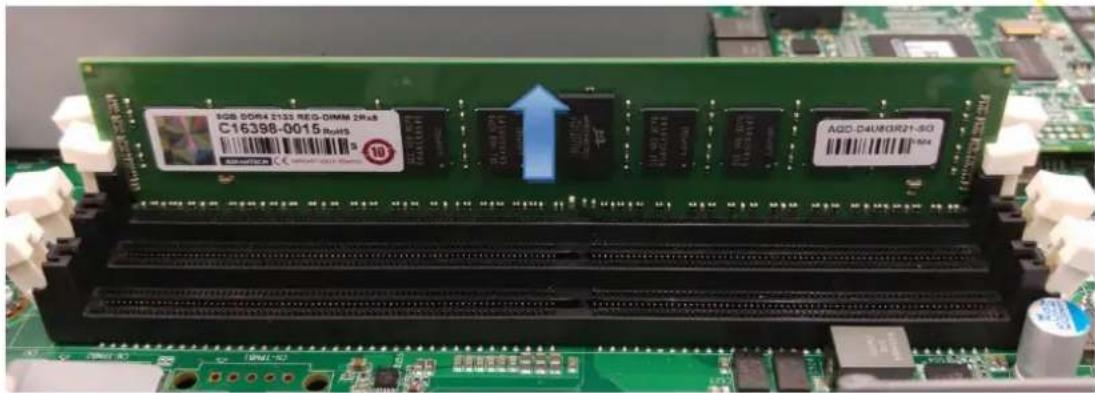
Figure 69: Unlocking and removing a DIMM
To insert a new DIMM please follow the process described in section 3.3.4.
A. APPENDIX: CONNECTOR PINOUT AND LED INFORMATION
This connector can be found at position F5.
Please note that this RJ45 connector for the console, in contrast to RJ45 connectors for network ports, does not feature any integrated LEDs.
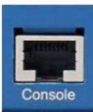
natural_image
Close-up of a black Ethernet port connector labeled 'Console' on a blue background (no additional text or symbols visible)Figure 70: RJ45 Console connector
| Pin No. | Signal Name | Description |
| 1 | n.c. | Not connected |
| 2 | n.c. | Not connected |
| 3 | TX | Transmit Data (Output from FWA-3260) |
| 4 | GND | Digital Circuit Ground |
| 5 | GND | Digital Circuit Ground |
| 6 | RX | Receive Data (input to FWA-3260) |
| 7 | n.c. | Not connected |
| 8 | n.c. | Not connected |
Table 45: Console connector pin assignment
A.2) USB Type A connectors
These connectors can be found at position
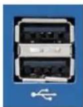
Figure 71: Stacked USB Type A connector
| Pin No. | Signal Name | Description |
| 1 | VCC_USB0 | USB Supply Voltage Port 0 (5V@500mA, fused) |
| 2 | USB0N | USB Port 0 Differential Pair |
| 3 | USB0P | |
| 4 | GND | Digital Circuit Ground |
| 5 | VCC_USB1 | USB Supply Voltage Port 1 (5V@500mA, fused) |
| 6 | USB1N | USB Port 1 Differential Pair |
| 7 | USB1P | |
| 8 | GND | Digital Circuit Ground |
Table 46: Stacked USB Type A connector pin assignment
A.3) RJ45 10/100/1000 BASE-T ports
These connectors can be found at positions F6 through F7
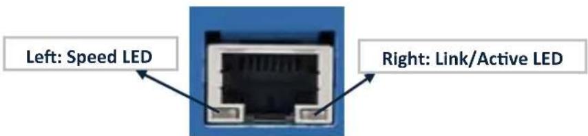
Figure 72: RJ45 10/100/1000 Base-T connector
Table 47: RJ45 10/100/1000 Base-T connector pin assignment
A.3.2) LED Definition
| Speed LED | Left(Green / Amber Color) | Link/Active LED | Right(Green / Amber Color) |
| 10 Mbps | Off | Link | Turn on Green |
| 100 Mbps | Static Amber | Active | Blinking Green |
| 1000 Mbps | Static Green | Bypass Status:Disconnect | Blinking Amber |
| Bypass Status:Bypass | Static Amber |
Table 48: RJ45 connector LED indication
Note: Bypass States are only signalled on the traffic LAN ports. Management LAN ports do not have this extra LED colour & signalling.
B. BIOS POST CODES
POST Codes are diagnostic codes sent by the BIOS to IO address 0x80. A POST adapter needs to be installed in the system to view these POST Codes. Codes not listed are reserved by AMI.
| POST Code | Description |
| 0x01 | Power on. Reset type detection (soft/hard). |
| 0x02 | AP initialization before microcode loading |
| 0x03 | North Bridge initialization before microcode loading |
| 0x04 | South Bridge initialization before microcode loading |
| 0x05 | unused |
| 0x06 | Microcode loading |
| 0x07 | AP initialization after microcode loading |
| 0x08 | North Bridge initialization after microcode loading |
| 0x09 | South Bridge initialization after microcode loading |
| 0x0A | unused |
| 0x0B | Cache initialization |
| 0x0E | Microcode not found |
| 0x0F | Microcode not loaded |
| 0x10 | PEI Core is started |
| 0x11 | Pre-memory CPU initialization is started |
| 0x12 | Pre-memory CPU initialization (CPU module specific) |
| 0x13 | Pre-memory CPU initialization (CPU module specific) |
| 0x14 | Pre-memory CPU initialization (CPU module specific) |
| 0x15 | Pre-memory North Bridge initialization is started |
| 0x16 | Pre-Memory North Bridge initialization (North Bridge module specific) |
| 0x17 | Pre-Memory North Bridge initialization (North Bridge module specific) |
| 0x18 | Pre-Memory North Bridge initialization (North Bridge module specific) |
| 0x19 | Pre-memory South Bridge initialization is started |
| 0x1A | Pre-memory South Bridge initialization (South Bridge module specific) |
| 0x1B | Pre-memory South Bridge initialization (South Bridge module specific) |
| 0x1C | Pre-memory South Bridge initialization (South Bridge module specific) |
| 0x1D – 0x2A | unused |
| 0x2B | Memory initialization. Serial Presence Detect (SPD) data reading |
| 0x2C | Memory initialization. Memory presence detection |
| 0x2D | Memory initialization. Programming memory timing information |
| 0x2E | Memory initialization. Configuring memory |
| 0x2F | Memory initialization (other). |
| 0x30 | Reserved for ASL |
| 0x31 | Memory Installed |
| 0x32 | CPU post-memory initialization is started |
| 0x33 | CPU post-memory initialization. Cache initialization |
| 0x34 | CPU post-memory initialization. Application Processor(s) (AP) initialization |
| 0x35 | CPU post-memory initialization. Boot Strap Processor (BSP) selection |
| 0x36 | CPU post-memory initialization. System Management Mode (SMM) initialization |
| 0x37 | Post-Memory North Bridge initialization is started |
| 0x38 | Post-Memory North Bridge initialization (North Bridge module specific) |
| 0x39 | Post-Memory North Bridge initialization (North Bridge module specific) |
| 0x3A | Post-Memory North Bridge initialization (North Bridge module specific) |
| 0x3B | Post-Memory South Bridge initialization is started |
| 0x3C | Post-Memory South Bridge initialization (South Bridge module specific) |
| 0x3D | Post-Memory South Bridge initialization (South Bridge modulespecific) |
| 0x3E | Post-Memory South Bridge initialization (South Bridge module specific) |
| 0x3F -0x4E | unused |
| 0x4F | DXE IPL is started |
| 0x50 | Memory initialization error. Invalid memory type or incompatible memory speed |
| 0x51 | Memory initialization error. SPD reading has failed |
| 0x52 | Memory initialization error. Invalid memory size or memory modules do not match. |
| 0x53 | Memory initialization error. No usable memory detected |
| 0x54 | Unspecified memory initialization error. |
| 0x55 | Memory not installed |
| 0x56 | Invalid CPU type or Speed |
| 0x57 | CPU mismatch |
| 0x58 | CPU self test failed or possible CPU cache error |
| 0x59 | CPU micro-code is not found or micro-code update is failed |
| 0x5A | Internal CPU error |
| 0x5B | reset PPI is not available |
| 0x60 | DXE Core is started |
| 0x61 | NVRAM initialization |
| 0x62 | Installation of the South Bridge Runtime Services |
| 0x63 | CPU DXE initialization is started |
| 0x64 | CPU DXE initialization (CPU module specific) |
| 0x65 | CPU DXE initialization (CPU module specific) |
| 0x66 | CPU DXE initialization (CPU module specific) |
| 0x67 | CPU DXE initialization (CPU module specific) |
| 0x68 | PCI host bridge initialization |
| 0x69 | North Bridge DXE initialization is started |
| 0x6A | North Bridge DXE SMM initialization is started |
| 0x6B | North Bridge DXE initialization (North Bridge module specific) |
| 0x6C | North Bridge DXE initialization (North Bridge module specific) |
| 0x6D | North Bridge DXE initialization (North Bridge module specific) |
| 0x6E | North Bridge DXE initialization (North Bridge module specific) |
| 0x6F | North Bridge DXE initialization (North Bridge module specific) |
| 0x70 | South Bridge DXE initialization is started |
| 0x71 | South Bridge DXE SMM initialization is started |
| 0x72 | South Bridge devices initialization |
| 0x72 | South Bridge DXE Initialization (South Bridge module specific) |
| 0x73 | South Bridge DXE Initialization (South Bridge module specific) |
| 0x74 | South Bridge DXE Initialization (South Bridge module specific) |
| 0x75 | South Bridge DXE Initialization (South Bridge module specific) |
| 0x76 | South Bridge DXE Initialization (South Bridge module specific) |
| 0x77 | South Bridge DXE Initialization (South Bridge module specific) |
| 0x78 | ACPI module initialization |
| 0x79 | CSM initialization |
| 0x80 – 0x8F | unused |
| 0x90 | Boot Device Selection (BDS) phase is started |
| 0x91 | Driver connecting is started |
| 0x92 | PCI Bus initialization is started |
| 0x93 | PCI Bus Hot Plug Controller Initialization |
| 0x94 | PCI Bus Enumeration |
| 0x95 | PCI Bus Request Resources |
| 0x96 | PCI Bus Assign Resources |
| 0x97 | Console Output devices connect |
| 0x98 | Console input devices connect |
| 0x99 | Super IO Initialization |
| 0x9A | USB initialization is started |
| 0x9B | USB Reset |
| 0x9C | USB Detect |
| 0x9D | USB Enable |
| 0xA0 | IDE initialization is started |
| 0xA1 | IDE Reset |
| 0xA2 | IDE Detect |
| 0xA3 | IDE Enable |
| 0xA4 | SCSI initialization is started |
| 0xA5 | SCSI Reset |
| 0xA6 | SCSI Detect |
| 0xA7 | SCSI Enable |
| 0xA8 | Setup Verifying Password |
| 0xA9 | Start of Setup |
| 0xAA | Reserved for ASL |
| 0xAB | Setup Input Wait |
| 0xAC | Reserved for ASL |
| 0xAD | Ready To Boot event |
| 0xAE | Legacy Boot event |
| 0xAF | Exit Boot Services event |
| 0xB0 | Runtime Set Virtual Address MAP Begin |
| 0xB1 | Runtime Set Virtual Address MAP End |
| 0XB2 | Legacy Option ROM Initialization |
| 0xB3 | System Reset |
| 0XB4 | USB hot plug |
| 0xB5 | PCI bus hot plug |
| 0xB6 | Clean-up of NVRAM |
| 0xB7 | Configuration Reset (reset of NVRAM settings) |
| 0xC0 – 0xCF | unused |
| 0xD0 | CPU initialization error |
| 0xD1 | North Bridge initialization error |
| 0xD2 | South Bridge initialization error |
| 0xD3 | Some of the Architectural Protocols are not available |
| 0xD4 | PCI resource allocation error. Out of Resources |
| 0xD5 | No Space for Legacy Option ROM |
| 0xD6 | No Console Output Devices are found |
| 0xD7 | No Console Input Devices are found |
| 0xD8 | Invalid password |
| 0xD9 | Error loading Boot Option (LoadImage returned error) |
| 0xDA | Boot Option is failed (StartImage returned error) |
| 0xDB | Flash update is failed |
| 0xDC | Reset protocol is not available |
| 0XE0 | S3 Resume is stared (S3 Resume PPI is called by the DXE IPL) |
| 0xE1 | S3 Boot Script execution |
| 0xE2 | Video repost |
| 0xE3 | OS S3 wake vector call |
| 0xE8 | S3 Resume Failed |
| 0xE9 | S3 Resume PPI not Found |
| 0xEA | S3 Resume Boot Script Error |
| 0xEB | S3 OS Wake Error |
| 0xF0 – 0xF4 | unused |
| 0xf8 – 0xFA | unused |
Table 49: BIOS POST Codes
C. APPENDIX: POWER SUPPLY SPECIFICATION
The FWA-3260 is available with a 250W AC PSU and 300W redundant AC PSU. The specifications for this power supply are listed below. Please consult your Advantech representative reg. other power supply options.
| Item | Specification | Comment / Conditions |
| Rating | 250W | 0..25°C ambient |
| AC input voltage | 90-264V, 47-63Hz | Auto ranging |
| Input Current | 3.5A rms max.@115V2.0A rms max.@230V | |
| Hold up time | 16ms min. | @ full load |
| Efficiency | 70% minimum | @ full load |
| MTBF | 100,000h @25°C and full load | Acc. to MIL-HDBK-217 |
| Safety | UL, CB, CE,CCC,CE, BSMI, KCC PFC acc. EN61000-3-2 | (EN60950) |
| EMI Compliance | FCC Part 15 Subpart J, Class ‘B’ 115 Vac operation.CISPR 22 Class ‘B’ 230 Vac operation.BSMI | |
| Environment | RoHS | “5 of 6” compliant |
| Protection | Output OverloadOutput Short CircuitOutput Over Voltage ProtectionOver Temperature Protection |
Table 50: Single AC Power Supply Specification
D. APPENDIX: DECLARATION OF CONFORMITY
The FWA-3260 has been successfully tested for compliance to the regulations below. Should you need a signed copy of the declaration of conformity or the related test reports, please contact your Advantech representative.
CE
This product has passed the CE test for environmental specifications when shielded cables are used for external wiring.
FCC Class A
Note: This equipment has been tested and found to comply with the limits for a Class A digital device, pursuant to part 15 of the FCC Rules. These limits are designed to provide reasonable protection against harmful interference when the equipment is operated in a commercial environment. This equipment generates, uses, and can radiate radio frequency energy and, if not installed and used in accordance with the instruction manual, may cause harmful interference to radio communications. Operation of this equipment in a residential area is likely to cause harmful interference in which case the user will be required to correct the interference at his or her own expense.
E. APPENDIX: WARRANTY AND RMA
Advantech warrants to you, the original purchaser, that each of its products will be free from defects in materials and workmanship for two years from the date of purchase.
This warranty does not apply to any products which have been repaired or altered by persons other than repair personnel authorized by Advantech, or which have been subject to misuse, abuse, accident or improper installation. Advantech assumes no liability under the terms of this warranty as a consequence of such events.
Because of Advantech's high quality-control standards and rigorous testing, most of our customers never need to use our repair service. If an Advantech product is defective, it will be repaired or replaced at no charge during the warranty period. For out-of-warranty repairs, you will be billed according to the cost of replacement materials, service time and freight. Please consult your dealer for more details.
If you think you have a defective product, follow these steps:
- Collect all the information about the problem encountered, for example, Advantech products used, other hardware and software used, etc. Note anything abnormal and list any onscreen messages you get when the problem occurs.
- Call your dealer and describe the problem. Please have your manual, product, and any helpful information readily available.
- If your product is diagnosed as defective, obtain an RMA (return merchandise authorization) number from your dealer. This allows us to process your return more quickly.
- Carefully pack the defective product, a fully-completed Repair and Replacement Order Card and a photocopy proof of purchase date (such as your sales receipt) in a shippable container. A product returned without proof of the purchase date is not eligible for warranty service.
- Write the RMA number visibly on the outside of the package and ship it prepaid to your dealer.
- Revision History
- About this manual
- Useful documents
- Warnings, Cautions and Notes
- We appreciate your input
- Acknowledgements
- Table of Contents
- GETTING STARTED.... 13
- PRODUCT SPECIFICATION ...... 26
- ADVANCED PLATFORM FEATURES 48
- AVAILABLE ACCESSORIES AND RELATED PRODUCTS....50
- CONFIGURATION AND SERVICE....51
- INSTALLING COMPONENTS 80
- List of Figures
- List of Tables
- Glossary
- GETTING STARTED
- Safety Instructions
- Safety Precautions per IEC704-1
- Safety Precautions - Static Electricity
- Unpacking
- Installation and Configuration
- Rack Mounting
- Powering On
- Connecting to the Console
- Installing an OS
- Pre-Installed reference OS
- Installing and/or boot an OS from a USB key
- Installing an OS via network boot
- Booting an OS via network boot
- Getting Help: Technical Support and Assistance
- PRODUCT SPECIFICATION
- Overview
- Product Versions
- System dimensions
- Regulatory Compliance
- CE Mark
- Detailed Description
- Front elements
- Table 8: Front elements
- LED details
- Rear Elements
- System block diagram
- Processor(s)
- Memory
- Chipset
- USB
- SATA
- Legacy Functions and IO
- Serial Ports
- SMBus
- Network interfaces (onboard)
- PCIe Expansion
- TPM Module
- LCD Module
- Mass Storage
- BIOS
- Password protection
- BIOS defaults
- PCIe Tree
- Platform Management
- Power Supplies
- Product Labelling
- Table 21: Product Labels
- Electronic label: FRU EEPROM
- Advanced Platform features
- Intrusion detection
- Watchdog
- LAN Bypass
- LAN Bypass Segments
- Bypass Watchdog Support
- LED Behaviour
- Available Accessories and Related Products
- Accessories
- CONFIGURATION AND SERVICE
- Jumper Settings
- BIOS Setup Menu
- Main Setup Menu
- Setting System Time and Date
- Platform Setup Menu
- Serial Port Console Redirection
- COM1 Console Redirection Settings
- USB Configuration
- Table 27: USB Configuration Menu
- Trusted Computing
- Trusted Computing with TPM module installed
- H/W Monitor
- Virtualization
- Platform Management
- Hardware
- Hardware Setup: CPU Configuration
- Hardware Setup: North Bridge Configuration
- PCI Express Port Configuration
- QPI Configuration
- Hardware Setup: South Bridge Configuration
- Table 36: Hardware Setup: South Bridge configuration Menu Items
- South Bridge Configuration: SATA Configuration
- USB Configuration
- ACPI Setting
- Runtime Error logging
- Server Mgmt
- Security Setup
- Note:
- POST & Boot Menu
- Compatibility Support Module (CSM) Configuration
- Save & Exit Menu
- Installing Components
- Removing the top cover
- You need:
- Reinstalling the top cover
- Disk Installation
- 2.5" HDD drive
- M.2 SSD
- Memory Installation
- Firmware Upgrades
- BIOS
- LAN Bypass
- Replacing FRUs
- Disk drives
- 2.5" HDD
- M.2 SSD
- CMOS Battery
- Warning!
- DIMMs
- APPENDIX: CONNECTOR PINOUT AND LED INFORMATION
- A.2) USB Type A connectors
- BIOS POST CODES
- APPENDIX: POWER SUPPLY SPECIFICATION
- APPENDIX: DECLARATION OF CONFORMITY
- CE
- FCC Class A
- APPENDIX: WARRANTY AND RMA
Brand : Advantech
Model : FWA-3260
Category : Baby Scale