
POC-W243L - Desktop computer Advantech - Free user manual and instructions
Find the device manual for free POC-W243L Advantech in PDF.


| Product Category | Desktop computer (Point-of-Care Terminal) |
| Brand | Advantech |
| Model | POC-W243L |
| Display Size | 23.8" wide TFT color LCD (16:9) |
| Resolution | 1920 x 1080 |
| Touchscreen | Projected capacitive; light transmission 0.85 |
| Processor | Intel Core i7/i5 7th Gen or Celeron 3965U |
| Memory | 1 x DDR4 SODIMM slot, up to 16 GB |
| Storage | Optional 2.5" SATA SSD/HDD |
| Expansion Slots | 2 x Full Mini-PCIe, 1 x M.2 |
| Rear I/O Ports | 2 x USB 3.0, 2 x USB 2.0, 2 x Gigabit Ethernet, 1 x DisplayPort, 1 x HDMI, 2 x COM RS232 (optional) |
| Power Supply | DC adapter 84 W; input 90-240 VAC, 1.3-0.8 A |
| Dimensions (W x D x H) | 583 x 386 x 69 mm (22.95" x 15.19" x 2.71") |
| Weight | 7.95 kg (17.52 lb) |
| Mounting | VESA 75x75 mm and 100x100 mm |
| Operating Temperature | 0°C to +40°C |
| Certifications | CE, CCC Class B, UL/FCC, BSMI |
| Safety Classification | Class I internal powered, no applied part, continuous operation, not suitable for flammable atmospheres |
| Cleaning Agents | Approved: Isopropyl alcohol, 70% alcohol, chloride 1000 PPM, Incidin, Mikrozid, etc. Do not use phenol or strong solvents. |
| Additional Features | Fanless design, optional WLAN/Bluetooth, RFID reader, IPS display |
Frequently Asked Questions - POC-W243L Advantech
User questions about POC-W243L Advantech
0 question about this device. Answer the ones you know or ask your own.
Ask a new question about this device
Download the instructions for your Desktop computer in PDF format for free! Find your manual POC-W243L - Advantech and take your electronic device back in hand. On this page are published all the documents necessary for the use of your device. POC-W243L by Advantech.
USER MANUAL POC-W243L Advantech
Point-of-Care Terminal with Intel® Core™ i7/i5/i3 and Celeron Processor, and a 23.8" TFT LCD
Instructions for the User
The document combines text and illustrations, providing a comprehensive overview of the system. The information is presented as a sequential steps of actions, allowing the user to learn directly how to use the device.
The text provides explanations and instructs the user step-by-step in the practical use of the product, with short, clear instructions in an easy-to-follow sequence.
Definitions
Warning! A WARNING statement provides important information about a potentially hazardous situation which, if not avoided, could result in death or serious injury.

Caution! A CAUTION statement provides important information about a potentially hazardous situation which, if not avoided, may result in minor or moderate injury to the user or patient or in damage to the equipment or other property.
Note! A NOTE provides additional information intended to avoid inconveniences during operation.

Safety Instructions
-
Strictly follow these Instructions for use, please read these safety instructions carefully.
-
Remind to keep this User's Manual for later reference, and any use of the product requires full understanding and strict observation of all portions of these instructions. Observe all WARNINGS and CAUTIONS as rendered throughout this manual and on labels on the equipment.
-
Repair of the device may also only be carried out by trained service personnel. Advantech recommends that a service contract be obtained with Advantech Service and that all repairs also be carried out by them. Otherwise the correct functioning of the device may be compromised.
Warning! Because of the danger of electric shock, never remove the cover of a device while it is in operation or connected to a power outlet.

Part No. 2008243L10 Edition 1
Printed in China Nov 2018
- If one of the following situations arises, get the equipment checked by service personnel:
■ The power cord or plug is damaged.
■ Liquid has penetrated into the equipment.
■ The equipment has been exposed to moisture.
The equipment does not work well, or you cannot get it to work according to the user's manual.
■ The equipment has been dropped and damaged.
■ The equipment has obvious signs of breakage.
- Disconnect this equipment from any AC outlet before cleaning. Use a damp cloth. Do not use liquid or spray detergents for cleaning and keep this equipment away from humidity.
Caution! To avoid short-circuiting and otherwise damaging the device, do not allow fluids to come in contact with the device. If fluids are accidentally spilled on the equipment, remove the affected unit from service as soon as possible and contact the service personnel to verify that patient safety is not compromised.

- Put this equipment on a reliable surface during installation. Dropping it or letting it fall may cause damage. For plug-in equipment, the power outlet socket must be located near the equipment and must be easily accessible.
Caution! To prevent overheating, do not cover the openings and place the device in direct sunlight or near radiant heaters.

- Make sure the voltage of the power source is correct before connecting the equipment to the power outlet. Position the power cord so that people cannot step on it. Do not place anything over the power cord. If the equipment is not used for a long time, disconnect it from the power source to avoid damage by transient over voltage.
Caution! Do not leave this equipment in an uncontrolled environment where the storage temperature is below -20^ C ( -4^ F) or above 60^ C ( 140^ F). this may damage the equipment.

- If your computer is losing dramatic time or the BIOS configuration reset to default, the battery has no power.
Caution! Do not replace battery yourself. Please contact a qualified technician or your retail.

The computer is provided with a battery-powered real-time clock circuit. There is a danger of explosion if battery is incorrectly replaced. Replace only with same or equivalent type recommended by the manufacture. Discard used batteries according to the manufacturer's instructions
Caution! The battery charging Indicator Is not Included In this device, and It shall be added In the end system assembly and be shown In the end system.

-
Improper installation of VESA mounting can result in serious personal injury! VESA mount installation should be operated by professional technician, please contact the service technician or your retail if you need this service. The detail operating procedure specified on Appendix A.
-
CLASSIFICATION:
1). Class I internal powered
2). No applied part
3). Continuous Operation
4). Not AP or APG category
Warning! This device is not suitable for use in the presence of flammable anesthetic mixture with air, oxygen, nitrous oxide, or for life support system.

- Environmental protection: follow national requirements to dispose of unit.
- Maintenance: properly maintain and clean the surfaces, use only the approved products or clean with a dry applicator.
Caution! When servicing the device, always use replacement parts that are qualified to Advantech standards. Advantech Medical cannot warrant or endorse the safe performance of third-party replacement parts for use with our medical device.
- Make sure the user does not contact the device and the patient at the same time.
Disposing of Your Old Product
Within the European Union

EU-wide legislation, as implemented in each Member State, requires that waste electrical and electronic products carrying the mark (left) must be disposed of separately from normal household waste. This includes monitors and electrical accessories, such as signal cables or power cords. When you need to dispose of your display products, please follow the guidance of your local authority, or ask the shop where you purchased the product, or if applicable, follow any agreements made between yourself.
The mark on electrical and electronic products only applies to the current European Union Member States.
FCC Class B
This equipment has been tested and found to comply with the limits for a Class B digital device, pursuant to Part 15 of the FCC Rules.
These limits are designed to provide reasonable protection against harmful interference when the equipment is operated in a residential environment. This equipment generates uses and can radiate radio frequency energy. If not installed and used in accordance with this user's manual, it may cause harmful interference to radio communications.
Note that even when this equipment is installed and used in accordance with this user's manual, there is still no guarantee that interference will not occur. If this equipment is believed to be causing harmful interference to radio or television reception, this can be determined by turning the equipment on and off. If interference is occurring, the user is encouraged to try to correct the interference by one or more of the following measures:
■ Reorient or relocate the receiving antenna
■ Increase the separation between the equipment and the receiver
■ Connect the equipment to a power outlet on a circuit different from that to which the receiver is connected
Consult the dealer or an experienced radio/TV technician for help
Warning!
Any changes or modifications made to the equipment which are not expressly approved by the relevant standards authority could void your authority to operate the equipment.

List of Accessories
Before installing your Point of Care Terminal, ensure that the following materials have been received:
■ POC-W243L series series Point-of-Care Terminal
■ Accessories for POC-W243L series
■ Mounting kits and packet of screws.
China RoHs note x1
Warning!

No user serviceable parts inside, refer servicing to qualified personnel. Only the accessories indicated on the list of accessories above have been tested and approved to be used with the device. Accordingly it is strongly recommended that only these accessories be used in conjunction with the specific device. Otherwise the correct functioning of the device may be compromised.
Additional Information and Assistance
Contact your distributor, sales representative, or Advantech's customer service center for technical support if you need additional assistance. Please have the following information ready before you call:
■ Product name and serial number
■ Description of your peripheral attachments
■ Description of your software (operating system, version, application software, etc.)
■ A complete description of the problem
■ The exact wording of any error messages
This equipment is a source of electromagnetic waves. Before use please, make sure that there are not EMI sensitive devices in its surrounding which may malfunction therefore.
Environmental protection
■ Follow national requirements to dispose of unit.
Manufacturer
Advantech Co., Ltd.
No.600, HanPu Load, Yushan, Kunshan Jiangsu, China, 215316
China, R.O.C.
TEL: (+86) 0512-57775666
Visit the Advantech websites at www.advantech.com or www.advantech.com.tw if you need more information.
Contents
Chapter 1 General Information ....1
1.1 Introduction 2
1.2 Specifications 2
1.3 Dimensions 4
Figure 1.1 Dimensions of the POC-W243L series.... 4
Figure 1.2 VESA Mounting of the POC-W243L Series....4
Figure 1.3 POC-W243L Series Front Panel .... 5
1.3.1 Optional Modules 5
1.3.2 Point-of-Care Terminal Cleaning and Disinfecting.... 5
1.4 Operating Principle....6
Chapter 2 System Setup....7
2.1 A Quick Tour of the POC-W243L Series.... 8
2.1.1 Front view 8
Figure 2.1 Front View of the Point-of-Care Terminal ....8
2.1.2 Rear View 9
Figure 2.2 Rear view of the Point of Care Terminal....9
Figure 2.3 Rear view of Multi I/O ports 9
2.2 Installation Procedures.... 10
2.2.1 Connecting the power cord 10
Figure 2.4 Connecting the power cord.... 10
2.2.2 Connecting the Ground pin 11
Figure 2.5 POC-W243L Series Equipotential Terminal Pin ..... 11
Figure 2.6 Grounding cable with connector .... 11
2.3 Running the BIOS Setup Program 11
2.4 Installing System Software.... 12
2.5 Installing the Drivers.... 12
Chapter 3 Operation and Safety ......15
3.1 General Safety Guide.... 16
3.2 Protecting Your Optical Drive....16
3.3 Thermal 16
3.4 Disconnect the Power 17
Appendix A POC-W243L Series VESA Mounting 19
A.1 Install VESA Mounting 20
Figure A.1 VESA mounting 20
Chapter 1
General Information
1.1 Introduction
POC-W243L is an 24" Industrial-grade computer with the latest computing capabilities and wide-viewing angles in a slim profile. The system is fanless, quiet, and energy efficiency. It delivers high-performance with an Intel® Core™ i7/i5 7th generation or Celeron® 3965U Dual-Core processor. With IPS (in-place switching) display, technology, customers can experience stunning images from any angle. Even with a 24" display, the entire unit weighs less than 8 kg and has a narrow profile depth of only 7 cm. The point-of-care terminal offers multiple connectivity which supports 2 x USB 3.0, 2 x USB 2.0, and one DP and HDMI. It's also equipped with single M.2 and Mini PCIe slots for expansion. This unit is ideally suited for applications in nursing care, especially integrated with lightweight measuring instruments or appliances. http://support.advantech.com.tw/support/
1.2 Specifications
| Computing System | CPU | Intel Kaby Lake Core i5-7300U & Celeron 3965U |
| Memory | 1 x DDR4 SODIMM slot (Default 4GB; Up to 16GB) | |
| Primary Storage Optional SATA SSD/HDD | ||
| Expansion Slot x 2 Full Mini-PCIe x 1 + M.2 Slot x 1 | ||
| Display | Display Size 23.8" wide TFT color LCD (16:9) | |
| Max. Resolution 1920 x 1080 (H x V) | ||
| Max. Colors 16.7 M colors (6-bits+A-FRC) | ||
| Pixel Pitch (um) 274.5 x 274.5 | ||
| Viewing Angle 178/178° | ||
| Luminance | 250 cd/m2 | |
| Backlight LED | ||
| Contrast Ratio 3000 : 1 | ||
| Touchscreen | Type Projected Capacitive | |
| Light Transmission 0.85 | ||
| Controller | FPC | |
| Durability | >100 million touches | |
| Resolution | Continuous | |
| Rear I/O | USB 3.0 | 2 x USB 3.0 |
| USB 2.0 | 2 x USB 2.0 | |
| LAN | 2 x Gigabit Ethernet (1.5KV isolated) interfaces (RJ45) | |
| Display PortOut Up to 4096 x2304 @60Hz | 1 x Displayport out | |
| HDMI out Up to 4096 x 2304 @ 24Hz | 1 x HDMI out | |
| Optional: COM RS232 serial port | 2 x COM RS232 (Optional) | |
| DC Jack 2pin | 1 x DC Jack | |
| Power Supply | DC Model | DC Adapter C14 DC PLUG 180° |
| Input Voltage | 90 ~240 Vac, 1.3~0.8 A @47~63Hz | |
| Audio | Speaker | 1.5 Watt x 2 |
| Optional Functions WLAN & Bluetooth | Qualcomm Atheros Dual-band (2.4/5GHz)802.11 a/b/g/n/ac 2Tx/2RxWifi &Bluetooth v4.1 (Optional V4.2) | |
| Certification CE &CCC Class B compliance;UL/FCC;BSMI | ||
| Environment | Temperature | Operating: 0°C ~ +40°C, Storage: -20°C ~ +60°C |
| Humidity | Operating: 10% ~ 90%@40°C non-condensed, Storage: 5% ~ 90%@40°C non-condensed, | |
| Shock Resistance 20G peak acceleration (11ms duration) | ||
| Pressure | 700-1013 hPa (Operation)700-1013 hPa (Storage)700-1013 hPa (Transportation) | |
| Storage SSD Either one of 2.5" SATA SSD | ||
| Physical Characteristics | Dimensions(W x D x H) | 583 x 386 x 69 mm(22.95" x 15.19" x 2.71") |
| Weight (Bare system) | 7.95 kg (17.52lb) | |
| VESA Mount 100x100 mm, 75x75 mm | ||
1.3 Dimensions
Dimensions: 583 x 386 x 69 mm (Unit: mm)
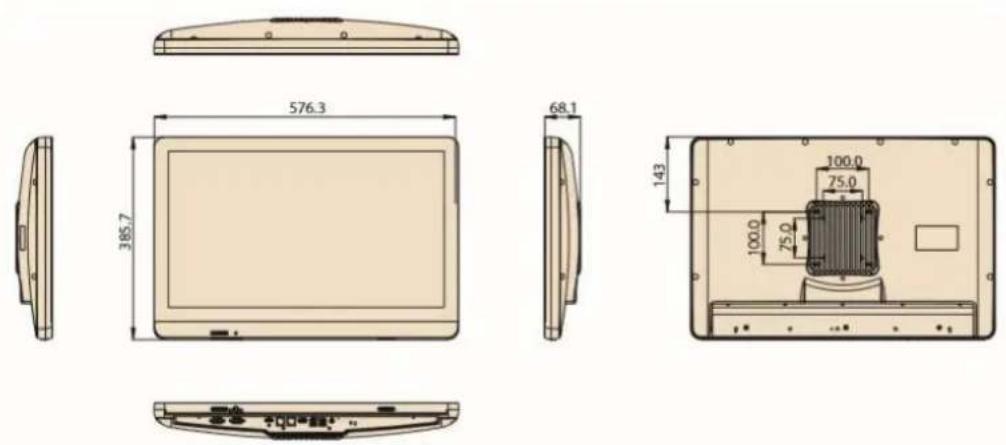
Figure 1.1 Dimensions of the POC-W243L series
VESA Mounting: 75 x 75 mm; 100 x 100 mm
Please use M4x12L (Maximum) screw.
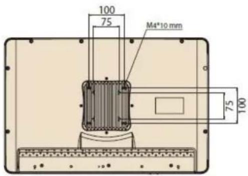
Figure 1.2 VESA Mounting of the POC-W243L Series
Warning! Use suitable mounting apparatus to avoid risk of injury.

natural_image
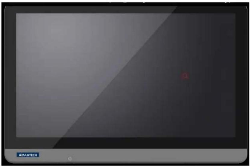
Exterior view of a modern office building (no signage)Figure 1.3 POC-W243L Series Front Panel
1.3.1 Optional Modules
■ Memory: Up to 32GB DDR4 SODIMM x 2
■ 2.5" SATA HDD (65 degree)/SSD, mini-PCIe mSATA
Dual-band (2.4/5GHz) 802.11n 2Tx/2Rx WiFi
Blutooth 4.2
RFID 13.56MHz, ISO-15693, ISO-14443A, ISO-14443B
1.3.2 Point-of-Care Terminal Cleaning and Disinfecting
During normal use of the POC (Point-of-Care Terminal) the device may become dirty and should be regularly cleaned.
Steps:
- Prepare cleaning agent per manufacturer's instructions or hospital protocol.
- Wipe the POC with a clean cloth moistened in cleaning solution.
- Wipe thoroughly with cloth.
Cleaning agent list: chemical disinfectants which have been tested on the POC
| No Cleaning Agents |
| 1 Cidex |
| 2 Isopropyl alcohol |
| 3 Green tinctured soap |
| 4 Windex |
| 5 Alcohol |
| 6 Alcohol 70% |
| 7 Chloride 1000PPM |
| 8 Incidin plus |
| 9 Incidin liquid |
| 10 Mikrozid liquid |
Caution!

Do not immerse or rinse the POC or its peripherals. If you accidentally spill liquid on the device, disconnect the unit from the power source. Contact your Biomed Department regarding the continued safety of the unit before placing it back in operation.
■ Do not spray cleaning agents on the chassis.
Do not use disinfectants that contain phenol. Do not autoclave or clean the POC or its peripherals with strong aromatic, chlorinated, ketone, ether, or Esther solvents, sharp tools or abrasives. Never immerse electrical connectors in water or other liquids.
Caution!

1.4 Operating Principle
The device provides input through the touch panel's hard keys located at the bottom and through USB or LAN/WLAN connections. The device is able to store data in its storage, and when the device is turned off, still maintain the data in the memory.
Chapter 2
System Setup
2.1 A Quick Tour of the POC-W243L Series
Before you start to set up the POC-W243L series, take a moment to become familiar with the location and purpose of the controls, drives, connections and ports, which are illustrated in the figures below.
When you place the POC-W243L series upright on the desktop, its front panel appears as shown in Figure 2.1.
2.1.1 Front view
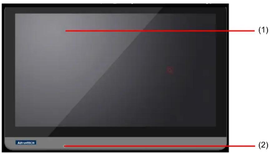
Figure 2.1 Front View of the Point-of-Care Terminal
Front Bezel view
(1) LCD panel with Touch Screen module
(2) Power symbol w/ indicator light
2.1.2 Rear View
When you turn the Point of Care Terminal around and look at its rear cover, the sunken I/O section is at the bottom of the panel PC, as shown in Figure 2.2 and zoom in Figure 2.3. (The I/O section includes various I/O ports, Ethernet port, USB ports and so on.)
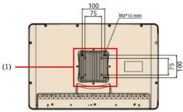
Figure 2.2 Rear view of the Point of Care Terminal
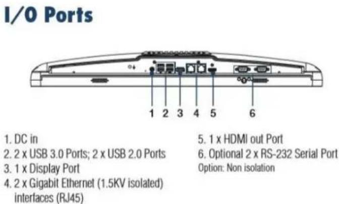
Figure 2.3 Rear view of Multi I/O ports
Note!
Equipotential terminal needs to be linked to the hospital ground/earth system before booting to protect operator and system.

2.2 Installation Procedures
2.2.1 Connecting the power cord
The POC-W243L can only be powered by a DC power adapter (FSP Model no.FSP084-DIBAN2). Be sure to always handle the power cords by holding the plug ends only.
Follow these procedures in order:
-
Connect the female end of the power adapter to the DC jack of the panel PC (see Figure 2.4)
-
Connect the female end of the power cord to the DC power adapter
-
Connect the 3-pin male plug of the power cord to an electrical outlet.
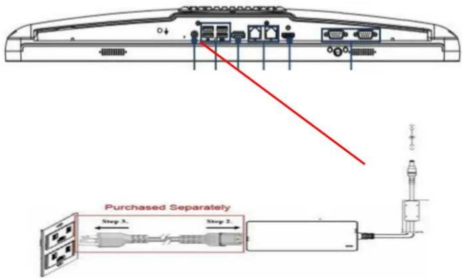
Figure 2.4 Connecting the power cord
Warning!The POC-W243L is supplied by a 84 watt power supply and a special adapter as depicted above.

If a medical adaptor is connected to the POC-W243L, the customer must ensure legal and regulatory compliance and that the device meets the laws and standards compliance requirements of this hardware.
2.2.2 Connecting the Ground pin
- To get the system ready, find the Equipotential Terminal on rear side of POC. An Equipotential Terminal is provided to optionally connect to a hospital ground/earth system.

natural_image
Technical line drawing of a computer rear panel with ports and connectors (no text or symbols)Figure 2.5 POC-W243L Series Equipotential Terminal Pin
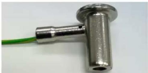
- Prepare the grounding cable and the other terminal link to hospital's ground/earth system.
natural_image
Close-up of a metallic T-shaped connector with a green cable extending from its tip (no text or symbols visible)Figure 2.6 Grounding cable with connector
- Grounding cable plug with POC-W243L series Equipotential Terminal (See Figure 2.5)
2.3 Running the BIOS Setup Program
Your POC-W243L series was probably set up and configured by your dealer prior to delivery. You may still find it necessary to use the BIOS (Basic Input-Output System) setup program to change system configuration information, such as the current date and time or your type of hard drive. The setup program is stored in read-only memory. It can be accessed either when you turn on or reset the panel PC, by pressing the "F2 or Del" key on your keyboard immediately after powering on the computer.
The settings you specify with the setup program are recorded in a special area of memory called CMOS RAM. This memory is backed up by a battery so that it will not be erased when you turn off or reset the system. Whenever you turn on the power, the system reads the settings stored in CMOS RAM and compares them to the equipment check conducted during the power on self-test (POST). If an error occurs, an error message will be displayed on screen, and you will be prompted to run the setup program.
2.4 Installing System Software
Recent releases of operating systems from major vendors include setup programs which load automatically and guide you through hard disk preparation and operating system installation. The guidelines below will help you determine the steps necessary to install your operating system on the panel PC hard drive.
Note! Some distributors and system integrators may have already pre-installed system software prior to shipment of your panel PC.

If required, insert your operating system's installation or setup diskette into the external diskette drive until the release button pops out.
The BIOS supports system boots up directly from the USB drive. You may also insert your system installation USB disk into your external USB drive.
Power on or reset the system by pressing the "F2 or Del" key to boot into BIOS menu and adjust the boot device sequence.
You can also press F12 key when booting; a bootable device popup menu will appear, you can select bootable device that you want. The Point-of-Care Terminal will automatically load the operating system from the diskette or USB Disc.
If you are presented with the opening screen of a setup or installation program, follow the instructions on screen. The setup program will guide you through preparation of your hard drive, and installation of the operating system.
2.5 Installing the Drivers
After installing your system software, you will be able to set up the Chipset, Graphics, Ethernet, audio, and touchscreen functions from your own external USB drive. All the drivers except the USB drive driver are stored in a USB disc entitled "Drivers and Utilities."
The standard automatic installation procedures for installing the chipset, graphics, audio, Ethernet, TXE and touch drivers are described in Chapter 3.
The various drivers and utilities in the USB disc have their own text files which help users install the drivers and understand their functions. These files are a very useful supplement to the information in this manual.
The driver can be downloaded from the following path: http://support.advantech.com.tw/support/
Troubleshooting
When system behaves abnormally, such as:
- Failure to power on
- Failure to power off
- Power LED ON but no DC power output
- AC power in and all switches ON, but system doesn't power on
Contact your distributor, sales representative, or Advantech's customer service center for technical support if you need additional assistance. Please have the following information ready before you call:
■ Product name and serial number
■ Description of your peripheral attachments
■ Description of your software (operating system, version, application software, etc.)
A complete description of the problem
■ The exact wording of any error messages
■ Symptoms, photo or video if available.
Chapter 3
Operation and Safety
3.1 General Safety Guide
For your own safety and that of your equipment, always take the following precautions. Disconnect the power plug (by pulling the plug, not the cord), from your computer if any of the following conditions exists:
■ The power cord or plug becomes frayed or otherwise damaged
■ You spill something into the case
- Your computer has been dropped or the case has been otherwise damaged
■ You suspect that your computer needs service or repair
■ You want to clean the computer or screen
■ You want to remove/install any parts
3.2 Protecting Your Optical Drive
To keep your optical drive working properly:
■ Position your computer so that the drive tray doesn't bump into
■ anything when it opens.
■ Close the drive when you're not using it.
- Do not put anything on the drive tray when it is open.
Do not touch the optical drive lens with your fingers. Do not wipe the lens with a paper towel or other abrasive surface.
3.3 Thermal
The vent hole of the POC-W243L series rear cover functions as a cooling air flow inlet and outlet. These air inlets and outlets transfer heat from inside the computer to the cooler air outside. Do not block these holes/vents with any soft material.
When using your POC-W243L series system, it is normal for the rear metal heatsink to get warm. The rear metal heatsink of the POC-W243L series functions as a cooling surface that transfers heat from inside the computer to the cooler air outside. Do not block this heatsink with any soft material.
Warning! Do not place your POC-W243L Series system on a pillow or other soft material when it is on, as the material may block the airflow and cause the computer to overheat.

3.4 Disconnect the Power
The only way to disconnect power completely is to unplug the power cord. Make sure at least one end of the power cord is within easy reach so that you can unplug the computer when you need to.
Warning! Your AC cord came equipped with a three-wire grounding plug (a plug

that has a third grounding pin). This plug will fit only a grounded AC outlet. If you are unable to insert the plug into an outlet because the outlet is not grounded, contact a licensed electrician to replace the outlet with a properly grounded outlet.
Do not defeat the purpose of the grounding plug.
Warning! Never push objects of any kind into this product through the openings in the case.

Doing so may be dangerous and result in fire or a dangerous electric shock.
Never place anything on system case before turning off the computer.
Never turn on your computer unless all of its internal and external parts are in place.
Operating the computer when it is open or missing parts can be dangerous and can damage
Appendix A
POC-W243L Series VESA Mounting
A.1 Install VESA Mounting
The POC-W243L Series also provides standard VESA mounting to help system integrators conveniently integrate the panel PC into their system.
Never use mounting brackets except as provided by Advantech to prevent unreliable mounting of the POC-W243L Series. VESA mount installation should be carried out by a professional technician; please contact a service technician or your retailer if you need this service.
Installation instructions follow:
-
First attach wall-mounting to the Heat-sink of the POC-W243L Series, securing it in place with four of the philips-head screws provided.
-
Mount the on the wall, stand or other flat surface.
Warning! Be sure to secure the screws of the mounting bracket tightly. A loose joint between the POC-W243L Series and mounting bracket may create danger of injury.

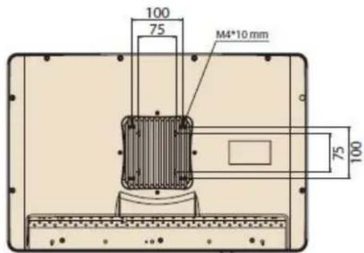
Figure A.1 VESA mounting
ADVANTECH
Enabling an Intelligent Planet
www.advantech.com
Please verify specifications before quoting. This guide is intended for reference purposes only.
All product specifications are subject to change without notice.
No part of this publication may be reproduced in any form or by any means, electronic, photocopying, recording or otherwise, without prior written permission of the publisher.
All brand and product names are trademarks or registered trademarks of their respective companies.
© Advantech Co., Ltd. 2018

- Instructions for the User
- Definitions
- Safety Instructions
- Disposing of Your Old Product
- FCC Class B
- List of Accessories
- Warning!
- Additional Information and Assistance
- Environmental protection
- Manufacturer
- Contents
- Chapter 1 General Information ....1
- Chapter 2 System Setup....7
- Chapter 3 Operation and Safety ......15
- Appendix A POC-W243L Series VESA Mounting 19
- Chapter 1
- Introduction
- Specifications
- Dimensions
- Optional Modules
- Point-of-Care Terminal Cleaning and Disinfecting
- Steps:
- Caution!
- Operating Principle
- Chapter 2
- A Quick Tour of the POC-W243L Series
- Front view
- Front Bezel view
- Rear View
- Installation Procedures
- Connecting the power cord
- Connecting the Ground pin
- Running the BIOS Setup Program
- Installing System Software
- Installing the Drivers
- Troubleshooting
- Chapter 3
- General Safety Guide
- Protecting Your Optical Drive
- Thermal
- Disconnect the Power
- Appendix A
- A.1 Install VESA Mounting
- ADVANTECH
- www.advantech.com
Brand : Advantech
Model : POC-W243L
Category : Desktop computer