
VPW4255 - TV VIEWSONIC - Free user manual and instructions
Find the device manual for free VPW4255 VIEWSONIC in PDF.


| Product Type | LCD TV |
| Brand | ViewSonic |
| Model | VPW4255 |
| Screen Size | 27 inches (full 27" viewable diagonal) |
| Display Type | TFT Active Matrix WXGA LCD |
| Native Resolution | 1280 x 720 |
| Aspect Ratio | 16:9 (widescreen) |
| Viewing Angles | Horizontal: +/-85°, Vertical: +/-85° |
| Video Inputs | VGA, DVI, YPbPr, Composite (CVBS), S-Video (via optional VXP10) |
| TV Tuner | Optional VXP25 module (NTSC/PAL/SECAM) |
| Audio Inputs | 3.5mm stereo jack, RCA L/R |
| Audio Outputs | 3.5mm headphone/speaker jack |
| Power Supply | 100-240 VAC, 50/60 Hz, 19V DC, 9.5A |
| Power Consumption | Normal: unspecified; Active Off: <5W |
| Dimensions (W x H x D) | 31" x 8.9" x 20.7" (786 x 225 x 526 mm) |
| Weight (Net) | 30.8 lbs (14.0 kg) |
| Operating Temperature | 32°F to 104°F (0°C to 40°C) |
| Storage Temperature | -4°F to 140°F (-20°C to 60°C) |
| Cleaning | Use soft, lint-free cloth; non-ammonia, non-alcohol based cleaners recommended |
| Safety | Do not remove rear cover; keep away from heat sources; use original power supply |
Frequently Asked Questions - VPW4255 VIEWSONIC
User questions about VPW4255 VIEWSONIC
0 question about this device. Answer the ones you know or ask your own.
Ask a new question about this device
Download the instructions for your TV in PDF format for free! Find your manual VPW4255 - VIEWSONIC and take your electronic device back in hand. On this page are published all the documents necessary for the use of your device. VPW4255 by VIEWSONIC.
USER MANUAL VPW4255 VIEWSONIC
natural_image
Front view of a modern computer monitor with a blank screen (no visible text or symbols)Full 27.0" Wide-Screen Entertainment Display
NextVision™ Wide-Screen Entertainment Display
User Guide
Quick Installation....5
Getting Started.... 12
Initial Setup 12
Using the On Screen Display (OSD) 15
Remote Controls 17
To adjust the screen image....18
Main Menu Controls.... 19
Picture Adjustment Tab....19
Display Adjustment Tab 24
TV Setting Tab (Requires connection of compatible VXP Adapter)......26
Audio Settings Tab 30
Parental Lock Tab....32
Set Up Tab 37
Input sources....39
Audio Sources 40
POP Screen 41
Other Information 42
Specifications 42
Compatibility....43
Troubleshooting....45
Customer Support 46
Cleaning the LCD TV 47
Limited Warranty 48
Appendix 49
Safety Guidelines....49
Compliance Information for U.S.A. 49
Copyright © ViewSonic Corporation, 2003. All rights reserved.
Macintosh and Power Macintosh are registered trademarks of Apple Computer, Inc.
Microsoft, Windows, Windows NT, and the Windows logo are registered trademarks of Microsoft Corporation in the United States and other countries.
ViewSonic, the three birds logo, OnView, ViewMatch, NextVision, and ViewMeter are registered trademarks of ViewSonic Corporation.
VESA is a registered trademark of the Video Electronics Standards Association. DPMS and DDC are trademarks of VESA.
Disclaimer: ViewSonic Corporation shall not be liable for technical or editorial errors or omissions contained herein; nor for incidental or consequential damages resulting from furnishing this material, or the performance or use of this product.
In the interest of continuing product improvement, ViewSonic Corporation reserves the right to change product specifications without notice. Information in this document may change without notice.
No part of this document may be copied, reproduced, or transmitted by any means, for any purpose without prior written permission from ViewSonic Corporation.
Product Registration
To meet your future needs, and to receive any additional product information as it becomes available, please register your product on the Internet at: www.viewsonic.com. The ViewSonic® Wizard CDROM also provides an opportunity for you to print the registration form, which you may mail or fax to ViewSonic.
For Your Records
Product Name: ViewSonic N2700w
Model Number: VSATV27330-1W
Serial Number:
Purchase Date:
Product disposal at end of product life
ViewSonic is concerned about the preservation of our environment. Please dispose of this product properly at the end of its useful life. Your local waste disposal company may provide information about proper disposal.
Installation
Congratulations on your purchase of a ViewSonic® NextVision® LCD TV.
Important! Save the original box and all packing material for future shipping needs.
The NextVision line of LCD TV is the next innovation from ViewSonic. Through the use of the new VXP port (located on the rear of the monitor) numerous expansion options are available for your NextVision LCD TV.
Precautions
- Sit at least 30" from your NextVision LCD TV.
- Avoid touching the screen. Skin oils are difficult to remove.
- Never remove the rear cover when the LCD TV power on. Your NextVision LCD TV contains high-voltage parts. Y0ou may be seriously injured if you touch them.
- Avoid exposing your NextVision LCD TV to direct sunlight or another heat source. Orient your NextVision LCD TV away from direct sunlight to reduce glare.
• Always handle your NextVision LCD TV with care when moving it. - Place your NextVision LCD TV in a well ventilated area. Do not place anything on your NextVision LCD TV that prevents heat dissipation.
- Ensure the area around the NextVision LCD TV is clean and free of moisture.
- Do not place heavy objects on the NextVision LCD TV, video cable, or power cord.
- If smoke, abnormal noise, or strange odor is present, immediately switch the NextVision LCD TV off and call your dealer or ViewSonic. It is dangerous to continue using the NextVision LCD TV.
Package Contents
Your NextVision package includes:
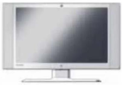
- NextVision N2700w LCD TV
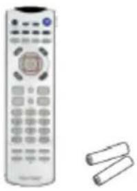
- Remote Control (included battery)
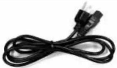
- US Power cord or Schuko (Europe) Power Cord
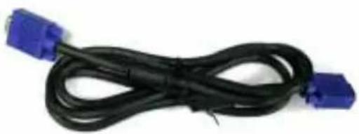
- Analog VGA Video Cable
- Audio cable (stereo mini jack)
- AC/DC Adapter
- Right Angle F-Connector or Right Angle Europe Connector.
- ViewSonic Wizard CD-ROM and Quick Start Guide
- The package may also include a VXP TV or Video Adapter
| N2700w LCD TV Remote Control | |
 |  |
| Power cord VGA Cable | |
 |  |
| 3.5mm Stereo Audio cable AC/DC Adapter | |
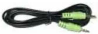 | 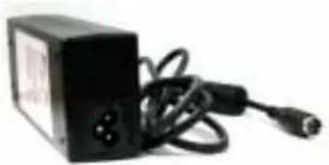 |
| VXP TV (VXP 25) orVideo Adapter (VXP 10) | Right Angle F-Connector (or Europe Connector) |
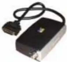 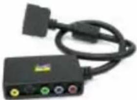 (VXP 25) (VXP 10) (VXP 25) (VXP 10) |   OR(F-Connector) (Europe Connector) OR(F-Connector) (Europe Connector) |
| Wizard CD-ROM Quick Start Guide / User Guide | |
 |   |
Quick Installation
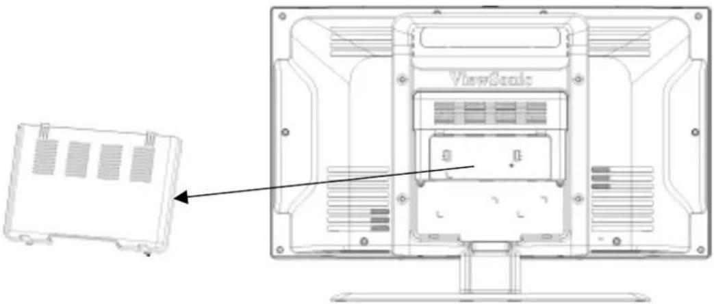
1 Remove one back panel cover
2. Connect a (optional) TV tuner or Video Module.
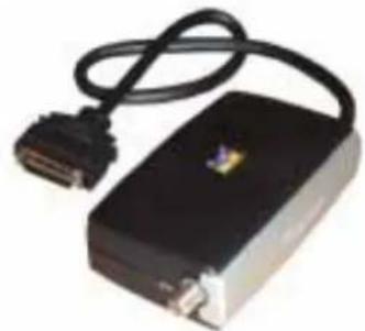
Depending on where purchased, your LCD TV may already include the VXP-25 TV Module (as shown below) or VXP 10 Video Adapter Module that allows connection to most AV Devices.
NOTE: The VXP-25 TV and VXP-10 Video Adapter modules may also be purchased separately, please contact ViewSonic for more information (www.viewsonic.com). Further detail about AV connections are included within the VXP Package.
• VXP 25: External Box that provides TV Tuner, CVBS, and YPbPr Input functionality.
• VXP 10: External Box that provides SVIDEO, CVBS, and YPbPr Inputs only (i.e. No TV Tuner).
- Right Angle F-Connector: External connector for VXP 25 may vary by region.
natural_image
Black electronic device with a USB cable and connector, no visible text or symbolsVXP25 TV Module
natural_image
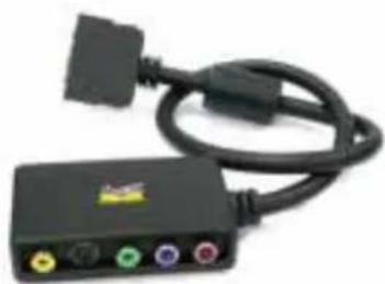
Black electronic device with black cable and connector ports (no visible text or symbols)VXP10 TV Module

Right Angle Adapter Figure (NTSC version shown)
2.1 Connect the right angle F-Connector to the VXP 25 TV module as shown:

natural_image
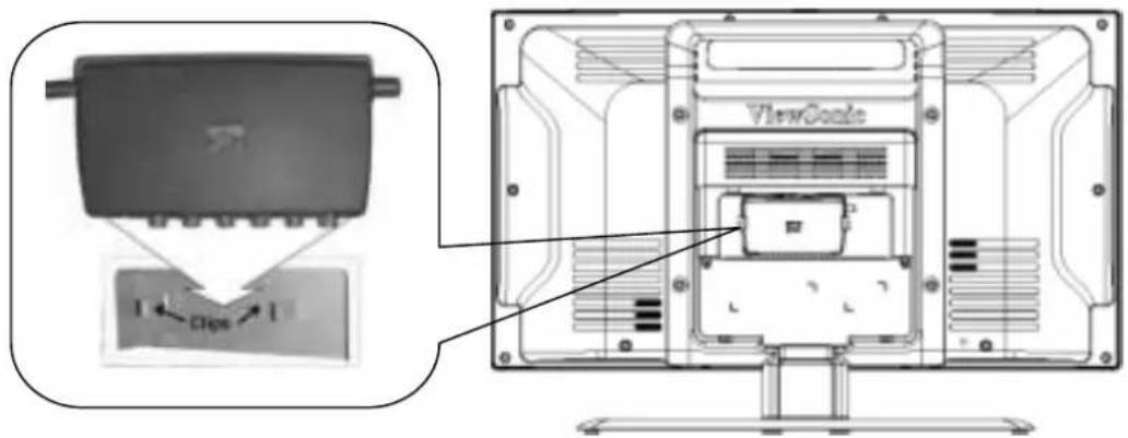
Two electronic devices connected by a cable, one showing ports and the other with a logo (no visible text or symbols on the device body)2.2 Mount the VXP 25 TV module under the hood and put the adapter into the clips on the back of the TV as following picture.
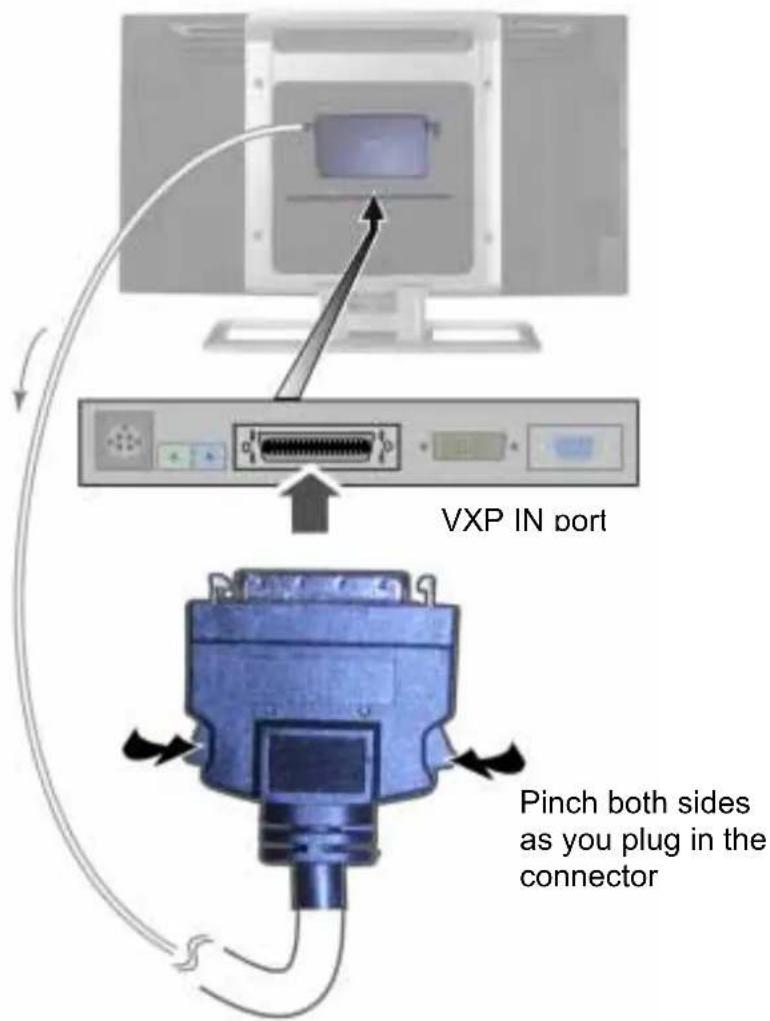
2.3. Connect the output cable of the VXP25 to the VXP input located on the LCD TV monitor.
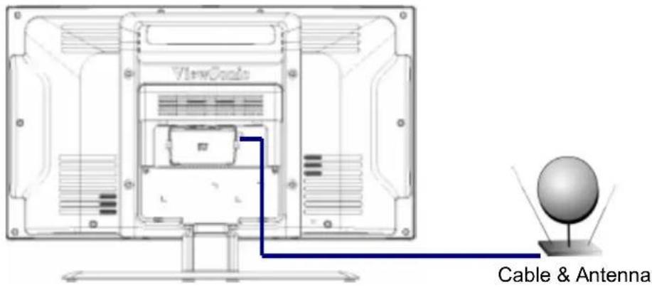
3 Connect VXP adapter to RF
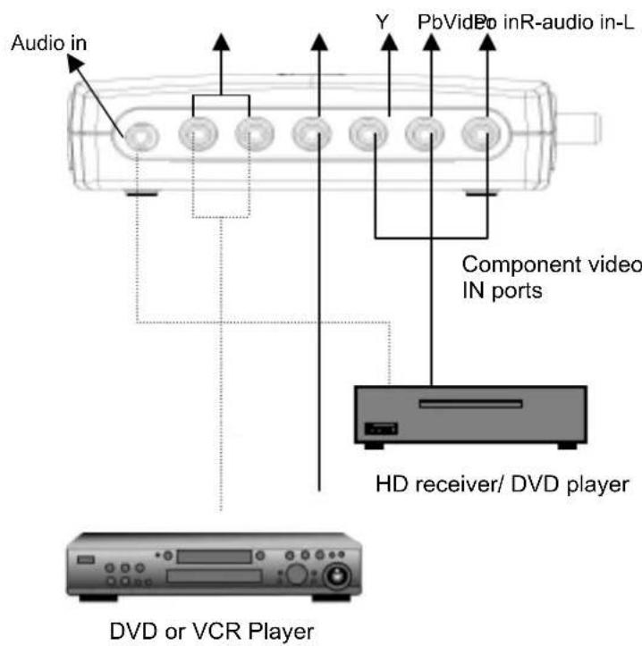
4 Connect AV
To play a video form DVD or VCR, you must connect the correct output ports to the correct input ports on the VXP adapter.
4.1 Composite video source: Connect with Video-in and R-audio in- L ports. Or connect the audio-in line with R and L audio-in.
4.2 YPbPr video source: please connect with Y, Pb and Pr Video-in and audio-line in (3.5mm stereo jack) ports.
(NOTE: If Desired, the RCA L /R Jacks may be used as an audio input corresponding to the YPbPr input; however a change on the OSD is required. See page 39)
4.3 S-video input. SVIDEO is only available on the optional VXP10 module. Contact ViewSonic at www.viewsonic.com for ordering information.
NOTE: "AUDIO IN" Jack requires (optional) Stereo Mini to RCA adapter. If desired, the "R-Audio In-L" (RCA) jacks may be used instead.
5.Audio Installation (optional)
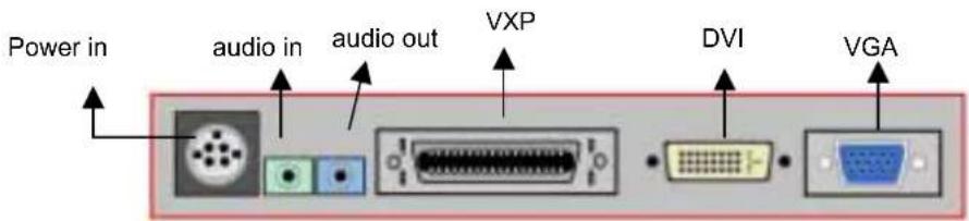
You can connect speakers or a headphone (3.5 mm ø mini-jack) to back audio-out port for listening.
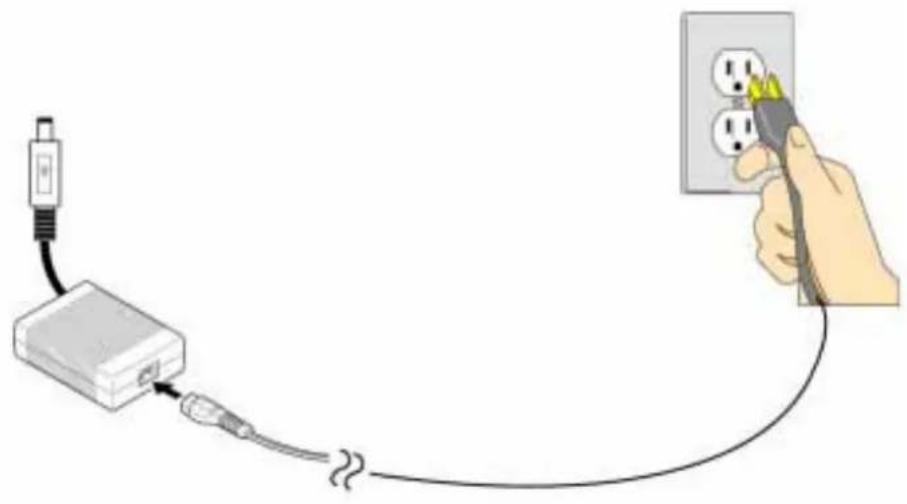
6. Connect power cord and AC/DC adapter
Connect the Power Plug form the DC power Supply to the Power Port on the back of the LCD TV.
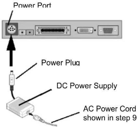
NOTE: always turn off the TV power when connecting the AC cords. Don't use power supply voltage other than 100-240 VAC. The violation may cause electric shock or fire.
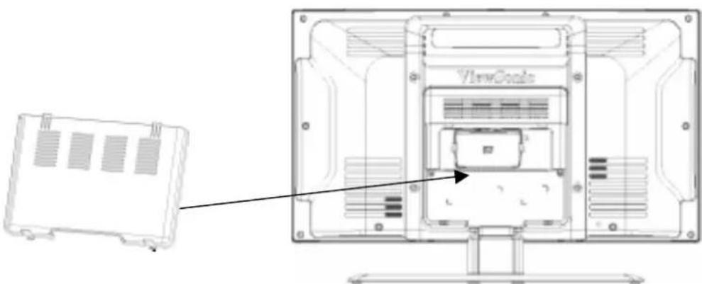
7. Installation is almost complete, please re-attach the back panel. And follow the initial setup to get starting to watch TV or Video.
natural_image
Technical line drawing of a computer monitor with a separate housing panel (no text or symbols)8. Plug into AC power source (wall outlet)
natural_image
Illustration of a hand inserting a plug into an electrical outlet connected to a USB cable (no text or symbols present)Installation with PC
1 Remove rear panel cover
2 Connect power cord and AC/DC adapter
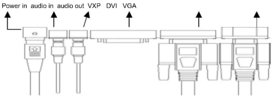
3 Connect video cable
- Make sure both the LCD TV and computer are turned OFF
- Connect the video cable (VGA or DVI port) from the LCD TV to the computer
- Macintosh users: Models older than G3 require a Macintosh adapter. Attach the adapter to the computer and plug the video cable into the adapter. To order a ViewSonic® Macintosh adapter, contact ViewSonic Customer Support.
Note: Only one RGB/DVI device may be connected at a time
4 Turn ON LCD TV and computer
Turn ON the LCD TV, then turn ON the computer.
NOTE: Windows users may receive a message asking them to install the INF file. This is on the CD.
5. Insert the ViewSonic Wizard CD into the computer's CD drive.
Follow the on-screen instructions If your computer does not have a CD-ROM drive, see "Customer Support."
(1) Wait for the CD-ROM to auto-start.
NOTE: If the CD-ROM does not auto-start: double-click on the CD-ROM icon in the Windows Explorer, then double-click on viewsonic.exe.
(2) Follow the on-screen instructions.
6. Audio Installation (optional)
Speakers Connect the audio cable to the AUDIO OUT port of your computer's sound card, then to the LCD TV's AUDIO IN port.
7. Windows users: Set the timing mode to 1280 x 720 @ 60Hz
Example: 1280 x 720 @ 60 Hz.
For instructions on changing the resolution and refresh rate, see the graphic card's user guide.
NOTE: The N2700w works best with 1280 x720 resolution (supported on many modern video cards). Most other common PC resolutions will work with reduced results.
8. Setting the Timing Mode (PC RGB Input)
Setting the timing mode is important for maximizing the quality of the screen image and minimizing eye strain. The timing mode consists of the resolution (example 1280 x 720) and refresh rate (or
vertical frequency; example 60 Hz). After setting the timing mode, use the OSD controls to adjust the screen image.
NOTE: For the best picture quality set your NextVision ^® LCD TV timing mode to: 1280 x 720 @ 60Hz.
To set the Timing Mode:
- Set the resolution: Right-click on the Windows desktop > Properties > Settings > set the resolution.
- Set the refresh rate: See your graphic card's user guide for instructions.
WARNING: Do not set the graphics card in your computer to exceed the maximum refresh rate of 75Hz; doing so may result in permanent damage to your LCD TV.
9. Choose a suitable video input sources for best image.
Pressing SOURCES button on the top of panel or via remote control to show an Input Sources menu. Set TV for TV function or set CVBS for AV function. (also see page 39 for the detail)
10. Installation is complete. Enjoy your new ViewSonic, LCD TV.
You can register your product online at the website for your region. See the Customer Support table in this guide. (page 46)
Getting Started
Initial Setup
1. Power on
1.1 Switch the POWER button on the front of panel or via remote control to turn on the TV.

| Indicator Explain | |
| Blue blinking The system is ready for Power on | |
| Blue Power on | |
| Amber blinking System reset | |
| Amber No signal detected | |
1.2 If you want to watch a video from DVD or VCR, please also turn on the AV device.
2. Set a language
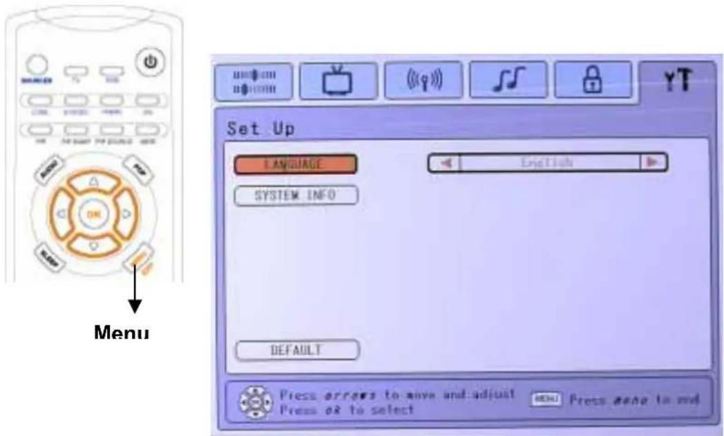
Set a language to suit your habit. Languages shall be defined by each region. Pressing MEMU button on the top of panel or via remote control to show an OSD menu. Choose Set Up tab to show the Language page and select available languages. (also see page 37 for the detail)
3. Input sources
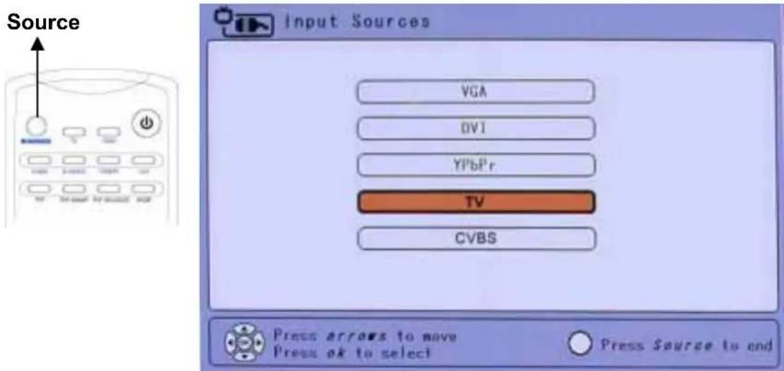
Choose a suitable video input sources for best image. Pressing SOURCES button on the top of panel or via remote control to show an Input Sources menu. Set TV for TV function or set Composite for AV function. (also see page 39 for the detail) Press the SOURCES button to end.
4.Set Tuner Input
4.1 NTSC system
Before using the built in TV tuner for the first time the following step must be completed. Please set TUNER INPUT to the appropriate RF system.
• Antenna: Select this for off-air use.
• CATV/ Japan CABLE: Select this if connected to the cable system.
- HRC/IRC: If connected to a cable system, see the documents that came from your service provider for more information.
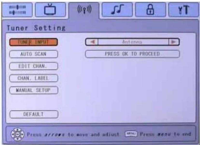
NOTE: If you are connecting to an external or internal antenna, "ANTENNA" is the correct choice. If you are connecting to a cable box "CATV" is the correct choice. Check with your local service
provider for detail. If set incorrectly, not all available channels will be viewable.
4.2 PAL system
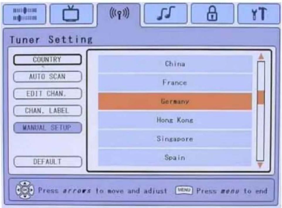
The PAL (Phase Alternation Line) is different from NTSC system that most be used in Europe and some of Asia area.
When you connect the VXP25 of PAL system, the TUNER SETTING Tab will display as following. Please choose one country that your location.
5. Auto-scan the TV channel
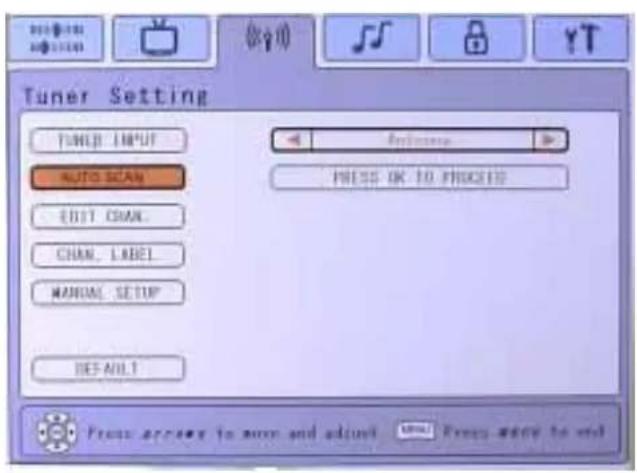
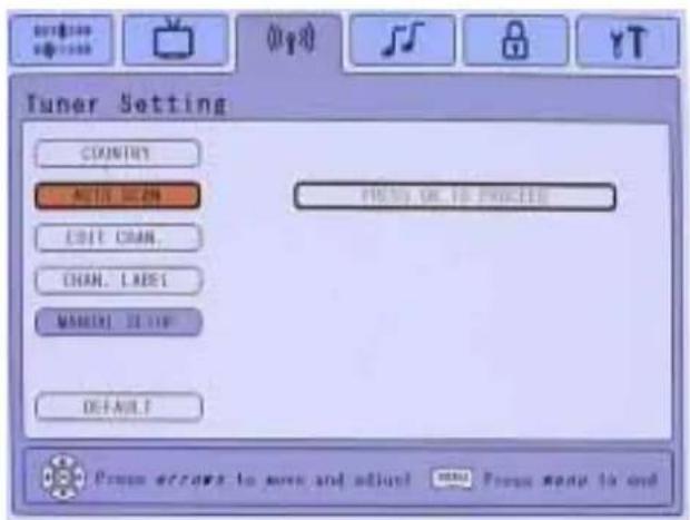
This function searches for and finds all available channels in your area.
First time you turn on the TV, you must automatically search all active channels. Pressing MENU button on the top of panel or via remote control to show an OSD menu. Choose AUTO SCAN page of Tuner Setting tab and pressing OK to scan channels.
5.2 PAL system 5.1 NTSC system
Using the On Screen Display (OSD)
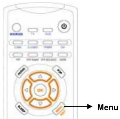
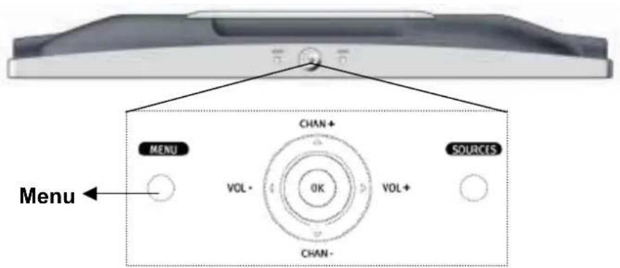
Use the buttons on the top panel or use the remote control to make all adjustments to the On Screen Display (OSD). The OSD controls are explained at the top of the next page and are defined in "Main Menu Controls" on page 19.
Remote Control
Top panel
Top Panel Shortcuts
Shortcuts allow quick access to commonly used functions without navigating through the OSD. The following shortcuts are available:
| Button Combinations Function | |
| MENU OSD Call / Dismiss | |
| UP / Down When OSD is active: OSD NavigationWhen OSD is NOT Active: Channel navigation | |
| Left / Right When OSD is active: OSD NavigationWhen OSD is NOT Active: Volume Control | |
| SOURCES | Open up Source Select Window (see page 39 for detail) |
| OK Acts as ENTER key within the OSD | |
| [OK](Hold for 0.5 Sec) | AUTO TUNE. Automatically adjusts Image Size, Position, and Phase in RGB mode. |
| [MENU] + [OK] + [SOURCES] +[RIGHT](Hold for 3.0 Sec) | System Reset.(Including Parental Control Password reset) |
| [MENU] + [LEFT](Hold for 5 Sec) | OSD LOCK TOGGLENote: Hold for 5 sec to dismiss |
| [MENU] + [RIGHT](Hold for 5 Sec) | POWER LOCKNote: Hold for 5 sec to dismiss |
Remote Controls
The N2700w remote control allows easy adjustment of all available options. The Remote Control is compatible with the LCD TV from up to 5m distance.
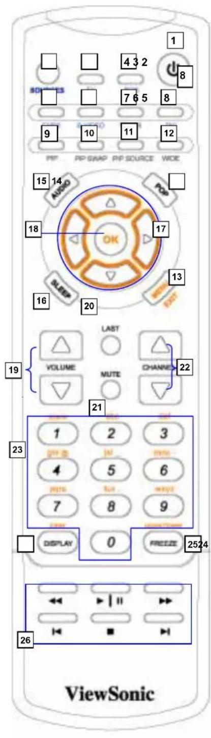
- Power :switch the power on/off
- Sources: Activates a menu listing all available input sources (see page 39 for detail)
- TV: Switches input to TV (if VXP25 is connected only)
- RGB: Switches input to the RGB Analog connection
- CVBS: Switches input to the Composite Analog connection (with VXP25 or VXP10 connected only)
- S-Video: Switches input to the S-Video connection
- YPbPr: Switches input to the YPbPr connection
- DVI: Switches input to the RGB Digital connection
- PIP: Toggles from small PIP, Large PIP, No PIP. The 4 way navigation will change the location of the PIP
- PIP Swap: Swap pictures from PIP to Full screen
- PIP Source: Rotate through all available PIP sources (see page 24 for detail)
12.WIDE: Toggle between WIDE1, WIDE2, and ZOOM 4X (This function is good to "Un-Letterbox" Letterboxed content). - Menu: Activates the OSD (see page 19 for detail)
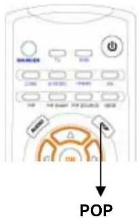
- POP: Activates the POP (see page 41 for detail)
- Audio: Activates a menu listing the possible audio sources (see page 40 for detail)
- Sleep: Activates or cancel the timer, which will turn the TV on/off. (see page 25 for detail)
- Arrow Up/down/ Lt/ Rt: Moves and adjusts selections in the OSD
- OK: Confirms selections with the remote and OSD
- Volume +/- :Controls volume levels
- Last: Tunes to the last channel
- Mute: Mutes activated audio source
- Channel -/+ : Changes descending channel
- 0-9: Inputs 0-9 for channel selections or OSD functions
- Display: Opens and closes the channel info
- Freeze: Freezes the frame. When this image has been frozen then the indicator will blinking.
- Reserved for future functionality.
NOTE: Additionally, when a VXP compatible adapter is installed, further utility is gained from the remote by allowing easy access to commonly used functions.
To adjust the screen image
- To display the OSD main menu, press MENU button of top panel or the MENU key of the remote control. User can use the four arrow keys to move the marker. Pressing MENU key when in the menu shall exit the OSD menu. (see page 15 for detail)
NOTE: All OSD menus and adjustment screens Time-out automatically after about 20 seconds.
-
The OSD is organized into "TABS" and "PAGES" pressing or scrolls through TABS. Pressing or navigates through the Pages.
-
After a Tab is selected, press button [OK], the functional page shall be displays.
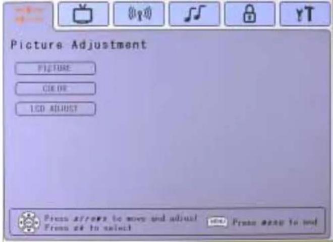
- Select a page and press button [OK]. A control screen like the one shown below appears.

- To save the adjustments and exit the marker, press button [Menu].
The following tips may help you optimize your LCD TV:
- Adjust your computer's graphic card so that it outputs a video signal 1280 x 720@ 60 Hz to the Display. (Look for instructions on “changing the refresh rate” in your graphic card's user guide.) If necessary, make small adjustments using H POSITION and V POSITION until the screen image is completely visible. (The black border around the edge of the screen should barely touch the illuminated “active area” of the NextVision LCD TV.)
Main Menu Controls
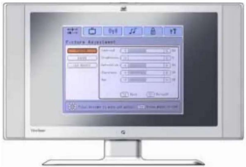
Function tabs include Picture adjustment, Display adjustment, Tuner Setting, Audio settings, Parental Lock and Setup. Press ← and → to choose function tab.
The selected Tab (Ex: Picture adjustment is shown) with includes multiple functions. (Ex: Picture, color, LCD Adjust are shown) Once a tab is selected by pressing OK then the functional page shall be displays. Each page shall have items that may be adjusted (Contrast being shown below).
NOTE: that the MARKER can be moved across the MAIN tabs horizontally. Please adjust the menu items shown below by using the up ↑ and down ↓ buttons.
Picture Adjustment Tab
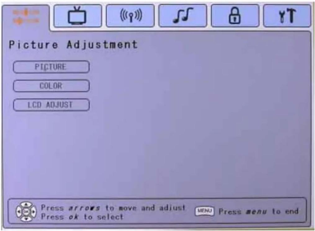
In the Picture adjustment main page, pressing OK then the functional page shall be displays.
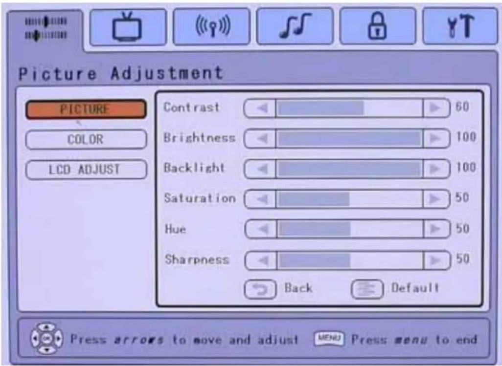
Picture Page
The Picture page allows adjustment or picture related items.
- ↑ and ↓ shall be used to navigate across the vertical page (Picture, Color, etc).
- Pressing OK shall invoke the selection (Contrast is shown).
- and keys shall be used to change the selected bar's value.
- ↑ and ↓ shall be used to navigate across the vertical lines (Contrast, Brightness, etc).
• Time out or MENU shall exit the OSD.
| Function Explanation | |
| CONTRAST | Adjusts the Contrast ratio of the image. |
| BRIGHTNESS | Adjusts the black-level (brightness) of the monitor. |
| BACKLIGHT | Adjusts the backlight of the monitor. |
| SATURATION | Adjusts the VIDEO COLOR SATURATION Level.a. This control is “Disabled” when a Full Screen PC Source is displayed.b. If a Full Screen PC Source and Video PIP is present, the control shall only affect the PIPC.Only present if compatible VXP adapter is detected. |
| HUE | Adjusts the VIDEO HUE Level. Only affects Full Screen Video and PIP Video Only.d. When FULL SCREEN PC is displayed, control shall be grayed out.e. Only present if compatible VXP adapter is detected. |
| SHARPNESS | For Full Screen Video adjusts the Video SHARPNESS.f. Has no effect on Full Screen PC Source.g. If PC + PIP Window, only affects PIP Source.h. Only present if compatible VXP adapter is detected |
| DEFAULT | Shall restore all functions to the factory default. Press Ok to take effect. |
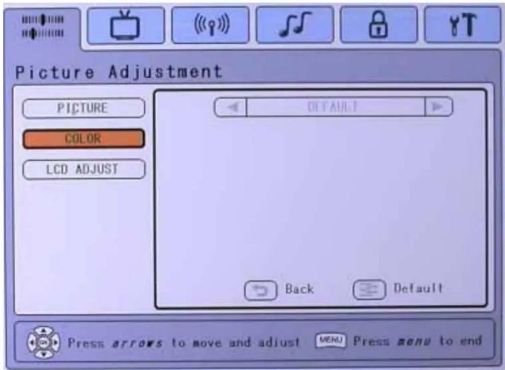
Color Page
- Move ↓ to the color page
- Pressing OK shall invoke the selection.
- and keys shall be used to change the selected bar's value (9300K, 6500K, etc).
• Time out or MENU shall exit the OSD.
| Function Explanation | |
| DEFAULT / COOL / STANDARD / WARM / USER COLOR | This control shall set the apparent “White” point of all displayed images.a. DEFAULT = Hi-Brightnessb. Cool = PRESET WHITE POINT. More blue bias.c. Standard = PRESET WHITE POINT. “TV” standard colord. Warm = PRESET WHITE POINT. More “Red” bias.e. User color: RGB controls appear on the user color is scrolled to. |
| DEFAULT | Resets the panel Color Temperature to “DEFAULT”. Press Ok to take effect. |
[NOTE]: These settings will be 'remembered' based on each active video input.
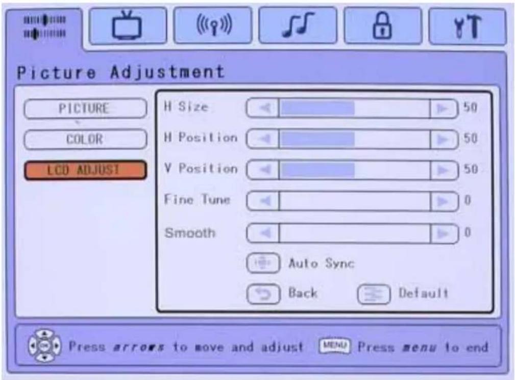
LCD Adjust Page
- Move ↓ to the LCD Adjust page
- Pressing OK shall invoke the selection (H. Size is shown)
- and keys shall be used to change the selected bar's value.
- ↑ and ↓ shall be used to navigate across the vertical lines (H. Size, H. Position, etc).
• Time out or MENU shall exit the OSD.
Function Explanation
| H SIZE This function will be active in PC mode. | |
| Allows the adjustment of Horizontal Size of the image. Normally not required to adjust as the monitor will automatically catch the correct setting. | |
| H POSITION This function will be active in PC mode. | |
| Allows the adjustment of the Horizontal Position of the image. Normally not required to adjust as the monitor will automatically catch the correct setting. | |
| V POSITION This function will be active in PC mode. | |
| Allows the adjustment of the Vertical Position of the image. Normally not required to adjust as the monitor will automatically catch the correct setting. | |
| FINE TUNE Allows the adjustment of random horizontal noise in the image. Normally not required to adjust as the monitor will automatically catch the correct setting. | |
| SMOOTHING The smoothing scroll will be appeared when the input sources is YPbPr mode. When the monitor is displaying a non-native (1280*720) signal. This control allows a Trade-ff between “smooth fonts” For Full Screen PC Source, acts as a ‘resolution smoothing’ filter for | |
| non-native resolution. (i.e. 640*480, 1024*768)There is 5 Settings to this Filter when in PC mode. 0 is no filtering, 5 is maximum filtering (more Blurry, but more filtering) | |
| AUTOSYNC | This function will be active in PC mode.Attempts to automatically fine tune. The image for best picture quality. For best result set display card to 1280x720@60Hz. |
| DEFAULT | Restores all settings to default. Press Ok to take effect. |
Display Adjustment Tab
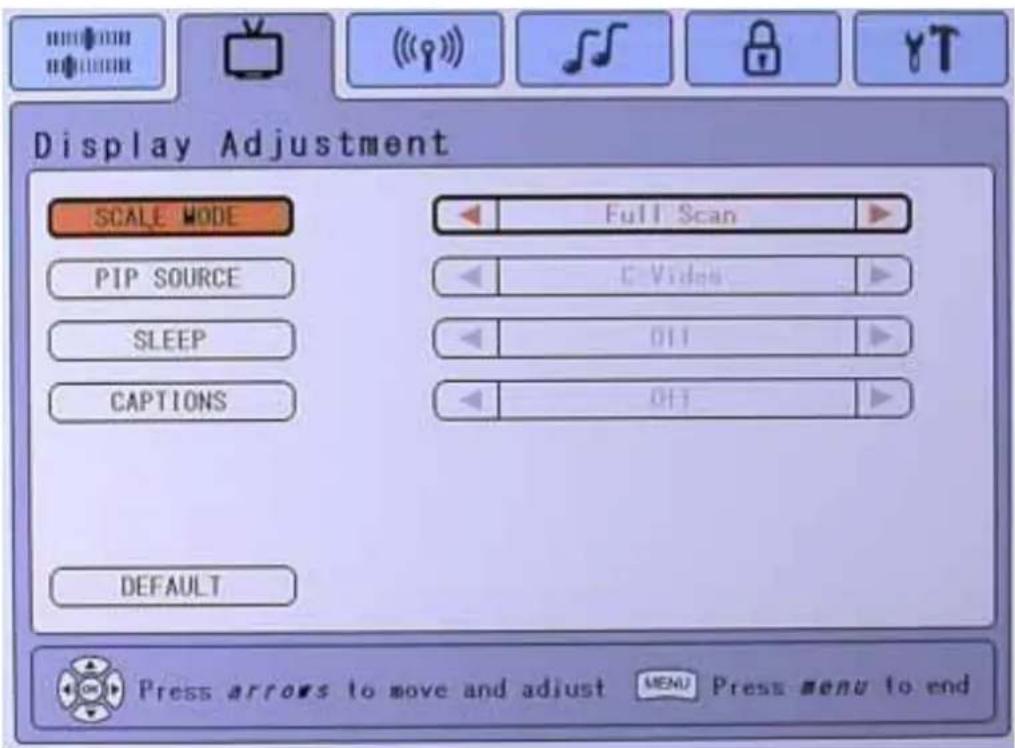
In the Display Adjustment Tab, pressing OK then the functional page shall be displays.
- Move ↑ and ↓ keys shall be used to navigate to the selection (Scale mode, PIP source, Sleep, Captions, Default)
- Pressing OK shall invoke the selection
- and shall be used to change the selected bar's value. (Full Scan, 1:1, etc.)
- ↑ and ↓ shall be used to navigate across the vertical lines (Full Scan, C-Video, etc)
• Time out or MENU shall exit the OSD.
Function Explanation
SCALE MODE
- These checkboxes determine how an incoming PC or video signal is scaled to be displayed on a panel.
a. Full Screen = Displays the incoming signal and scales the image to use ALL available pixels on the screen.
b. 1:1 = Displays the image in it's 'native' resolution using exactly a one to one correspondence in input vs. output pixels. A "Black Box" shall surround all non-used pixels.
c. Aspect Ratio = Scales the image as large as possible, but maintain the signal's correct aspect ratio. Non-used area of the screen shall be 'black-boxed'
PIP SOURCE
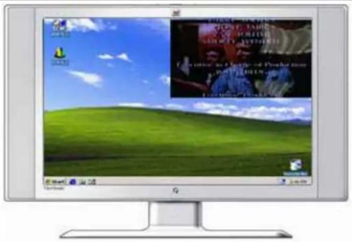
Picture in Picture (PIP) function can shows another channel or video source in 1/4 or 1/16 window superimposed in a corner of the screen. Defines the source from where the Picture in Picture (PIP) is to be displayed when activated by the Remotes "PIP" button. Requires connection of compatible VXP adapter and the input sources must be set in RGB and DVI mode.
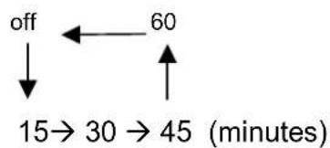
SLEEP Allows the user to select a preset amount of time before the system turns itself 'OFF' and put the monitor into DPMS State. Requires connection of compatible VXP adapter.
There are 15, 30, 45, 60 minutes sleeping time can be chosen and stop sleeping time the "off" value is selected.
flowchart
graph TD
    A["off"] --> B["15→30→45 (minutes)"]
    C["60"] <--_D["←"]
    E["↑"] --> F["↑"]
Allows the user to select the type (CC1, CC2, Text1, Text2) of closed caption required. Requires connection of compatible VXP adapter.
Returns this page back to factory default settings.
Tuner Setting Tab
(Requires connection of compatible VXP Adapter)
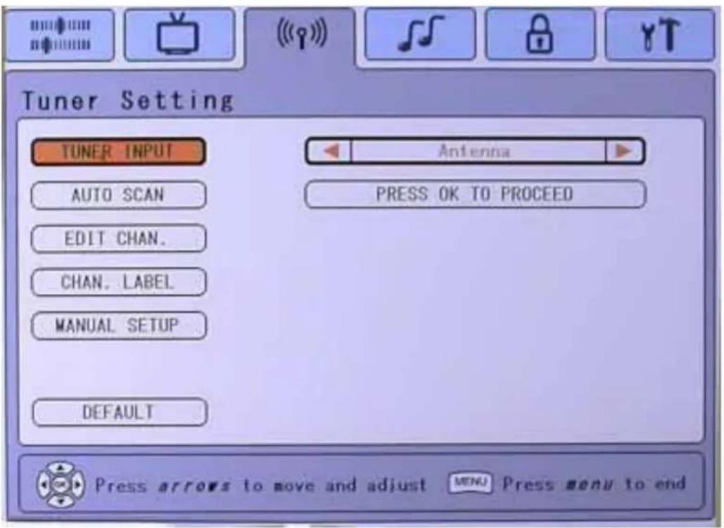
In the Tuner Setting Tab, pressing OK then the functional page shall be displays.
- Move ↑ and ↓ keys shall be used to navigate to the selection (Tuner Input, Auto Scan, Edit Chan, Chan. Label, Manual Setup).
- Pressing OK shall invoke the selection
- and shall be used to change the selected bar's value. (Antenna)
• ↑ and ↓ shall be used to navigate across the vertical lines
• Time out or MENU shall exit the OSD.
Function Explanation
| TUNER INPUT | Allows the user to select the type of signal applied to the TV INPUT. This controls options will vary by region. |
| 1. B/G, I, D/K, L shall be selectable under PAL system that most be used in Europe, China and Singapore area. | |
| 2. ANTENNA, CATV, HRC, IRC, Japan Cable shall be selectable under NTSC system that most be used in Asia and USA area. | |
| AUTO SCAN | If selected, initiates a Channel AutoScan. The LCD TV shall scan and find all ‘active’ channels. |
| DEFAULT | Restores all controls to default. |
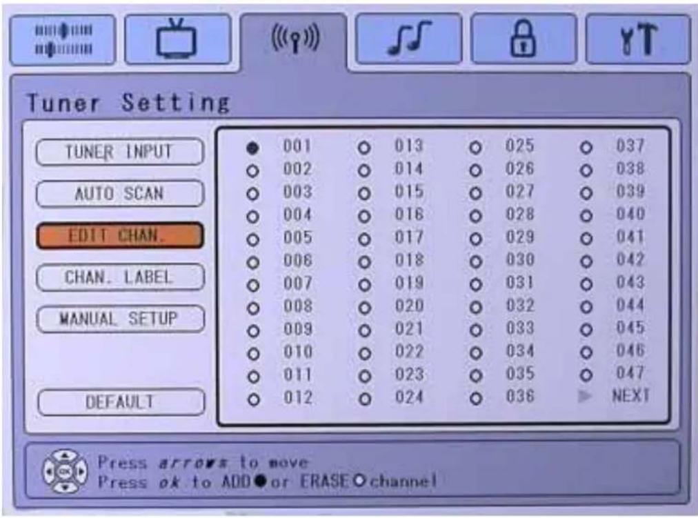
- Move ↓ to EDIT CHAN Page.
- Pressing OK shall invoke the selection
• ←, →, ↑ and ↓ keys shall be used to navigate to the selection - Pressing OK to Add or Erase channel.
• Time out or MENU shall exit the OSD.
Function Explanation
EDIT CHAN. Allows the user to add/erase the current channel to the internal database of active channels.
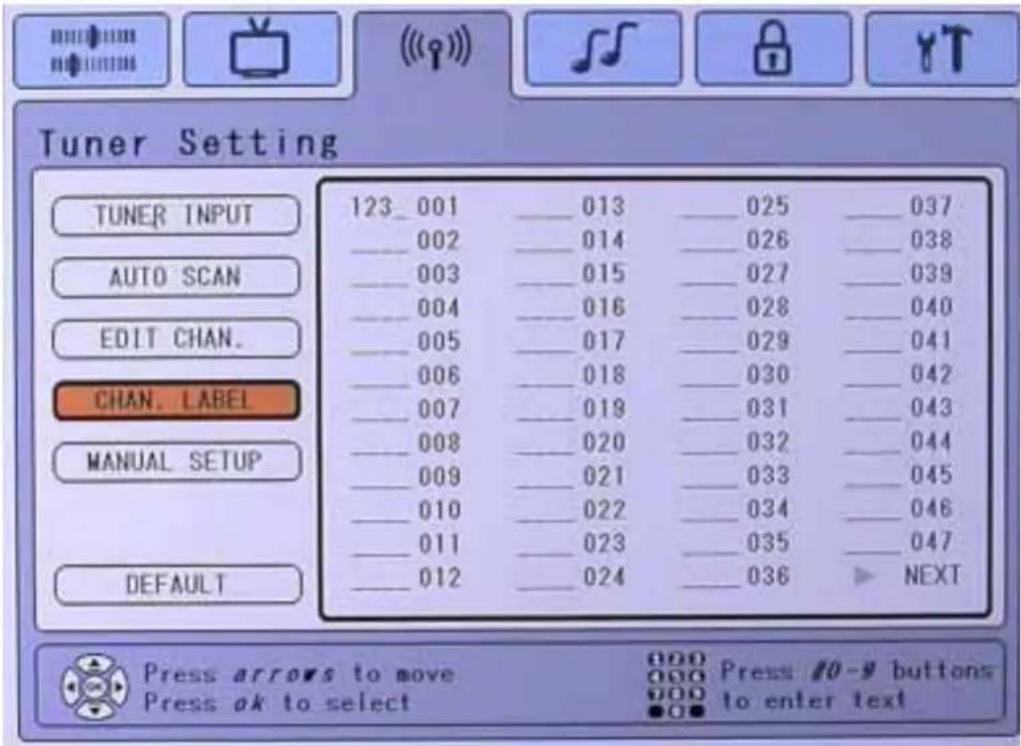
Chan Label Page
- Move ↓ to CHAN LABEL Page.
- Pressing OK shall invoke the selection
- , , and shall be used to navigate across the text field
- Pressing Ok shall invoke the channel label
- Pressing # 0\~9 buttons on remote control to enter numbers and letters.
- Pressing ok will bring you out so you can select the next channel label.
• Time out or MENU shall exit the OSD.
[NOTE]: Only present if VXP TV Adapter or similar adapter is detected.
Function Explanation
CHAN. LABEL The Channel Label allows the user to enter in the current channel's 4-Character that displayed as static text on top of page.
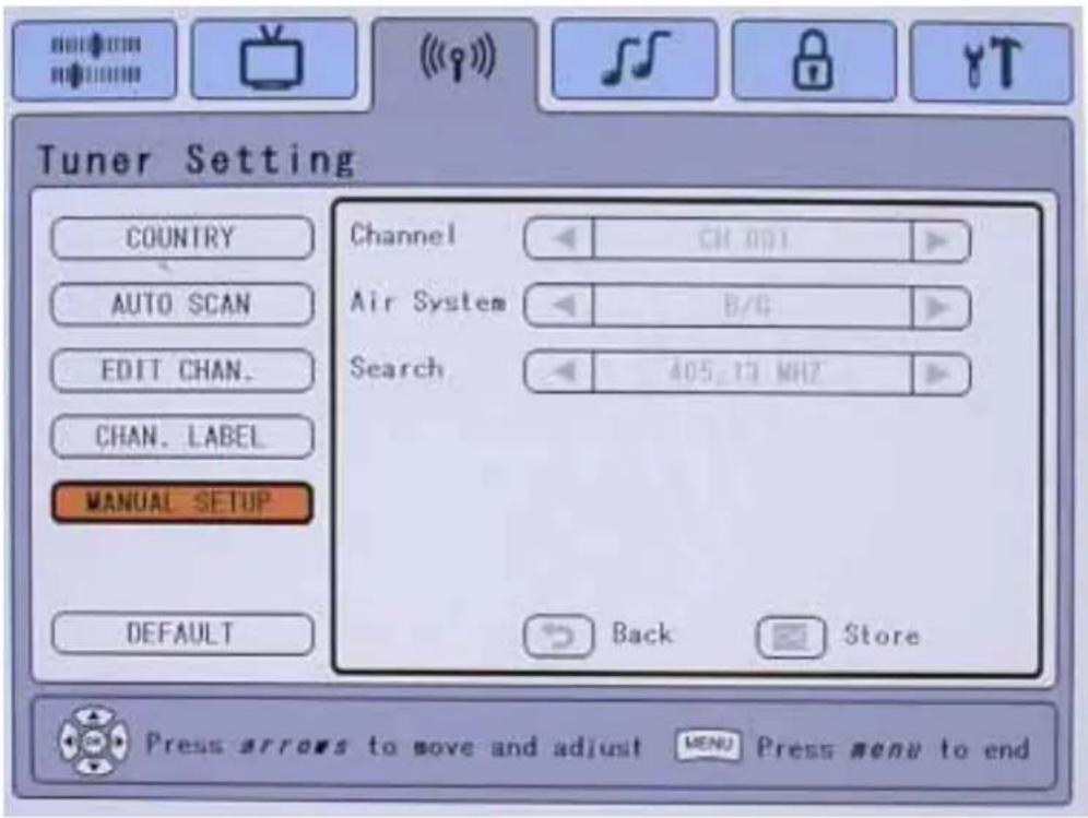
Manual Setup Page
NOTE: The Manual Setup Page shall be shown if you connect VXP 25 of PAL system.
- Move ↓ to Manual Setup Page.
- Pressing OK shall invoke the selection
- and shall be used to navigate across the available options
- ↑ and ↓ keys shall be used to navigate across the vertical lines
- Pressing Store to save the setting
• Time out or MENU shall exit the OSD.
Function Explanation
| CHANNEL | You can search channel |
| AIR SYSTEM | You can choose one air system type that controls options will vary by region. B/G, I, D/K, L shall be selectable in PAL system.Normally not required to adjust as the audio input will automatically to carry out. |
| SEARCH | Search automatically to catch the correct frequency |
Audio Settings Tab
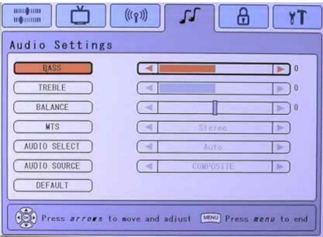
In the Audio Settings Tab, pressing OK then the functional page shall be displays.
Audio Settings Page
- Move and keys shall be used to navigate to the selection (Bass, Table, Balance, etc).
- Pressing OK shall invoke the selection
- and shall be used to change the selected bar's value.
• ↑ and ↓ shall be used to navigate across the vertical lines
• Time out or MENU shall exit the OSD.
NOTE: sound is determined by the video source
| Function Explanation | |
| BASS Audio BASS Control. Range of this control – 50 to +50 with 0 being (Default). | |
| TREBLE Audio Treble Control. Range of this control – 50 to +50 with 0 being (Default) . | |
| BALANCE Audio Balance Control. Range of this control – 50 to +50 with 0 being Nominal (Default) and Middle value. | |
| MTS(NTSC system) | If you connect the VXP25 of NTSC system, the MTS controller will be shown. Allows selecting MTS (Multi-channel Television on Sound) Mode, Stereo sound, Mono sound, or SAP (Secondary Audio Programs).SAP: listen to second language, supplementary commentary and other informationMay vary by region. Requires a compatible VXP adapter to be detected. |
| STEREO AUDIO (PAL system) | If you connect VXP25 of PAL system, the Stereo Audio controller will be shown. Allows selecting Stereo A/B sound and Mono sound.May vary by region. Requires a compatible VXP adapter to be detected |
| AUDIO SELECT | This selection allows the active audio source to be selected from the main window (AUTO - DEFAULT) or PIP. Selecting PIP allows the user to use his PC, but listen to audio from the PIP. Requires a compatible VXP adapter and PIP to be available. (see page 39 for detail) |
| AUDIO SOURCE | Choose audio source from TV, on board, Audio in and CVBS Selection. But you can not store the setting. |
| DEFAULT Restores this pages controls factory default settings: | |
Parental Lock Tab
(Requires compatible VXP adapter and compatible content. May not work in all areas)
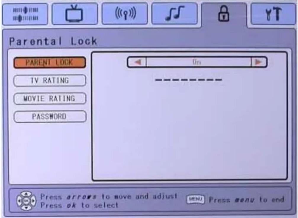
In the Parental Lock Tab, pressing OK then the functional page shall be displays.
Parental Lock Page
• → to OK password field
- Enter the password and press OK (unlock the parental control selections)
NOTE: When you forget your password, please press [OK] + [SOURCES] + [MENU]+[RIGHT] to reset the system and set a new password again.
Explanation
PARENTAL LOCK
The Parental Lock default is "off". Select "On" to set password then multi-functions will display including TV, rating, movie rating and password page.
After you set one password, you must key in password when you entry this page again. If you key in a wrong password the message "Password not match" will be shown.
Parental Lock Warning Messages
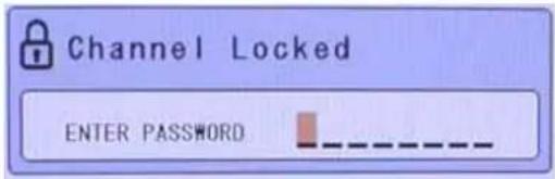
1.Channel Lock
This message would appear if the user tunes to a channel that is locked. You can bypass and unlock the channel immediately by entering your password. The channel will stay unlocked until the TV is power down.
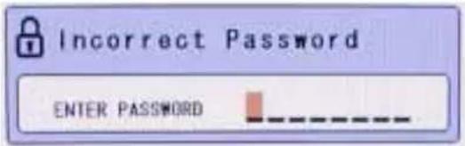
2.Incorrect Password
This message would appear if the user enters the incorrect password.
3.Channel Unlocked Confirmation
This message appears once the correct password has been entered and the channel has successfully unlocked. This message will time out after 3 seconds.

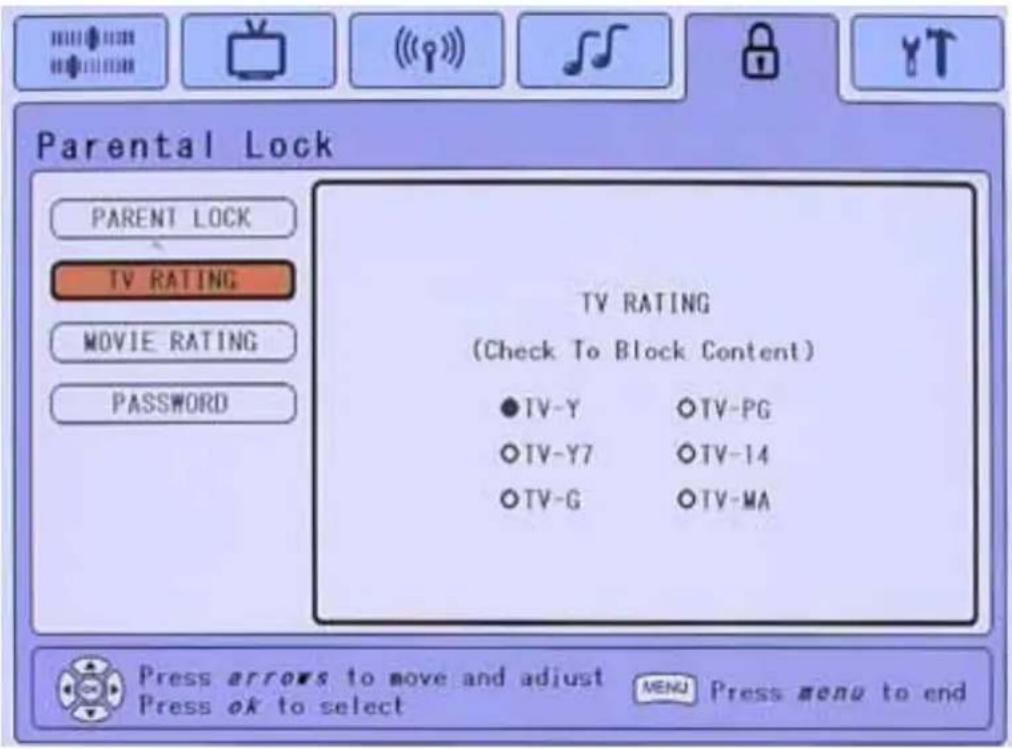
TV Rating Page
- Move to TV Rating Page and pressing OK shall invoke the selection
- , , and keys shall be used to navigate to the selection
- Pressing OK to Add or Erase item.
• Multiple selections are possible.
• Time out or MENU shall exit the OSD.
•
[NOTE]: This menu will appear if the Parental Lock is on.
Function Explanation
TV RATING Allows the user to select the TV rating of the Parental Control Connection.
1. TV-Y: Suggested for all children
2. TV-Y7: Directed to older children
3. TV-G: General audiences.
4. TV-PG: Parental guidance suggested
5. TV-14: Parental strongly cautioned
6. TV-MA: Mature audience only
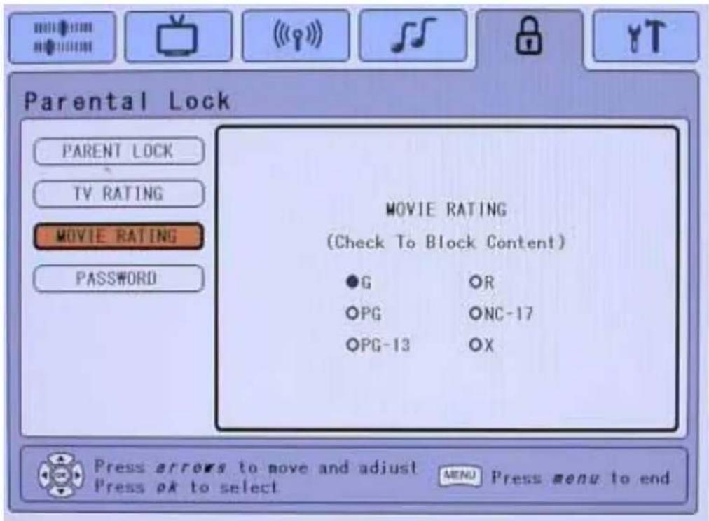
Movie Rating Page
- Move to Movie Rating Page and pressing OK shall invoke the selection
• ←, →, ↑ and ↓ keys shall be used to navigate to the selection - Pressing OK to Add or Erase item.
• Multiple selections are possible.
• Time out or MENU shall exit the OSD.
[NOTE]: This menu will appear if the Parental Lock is on.
If the "R" rating has been selected, the higher ratings like "NC-17" and "X" will automatically block.
Function Explanation
| MOVIE RATING | Allows the user to select the Movie Rating of the Parental Control function. Programs failing this test are ‘blue-screened’ out, with a message stating that the rating has exceeded the requirement.7. G: General audiences. All ages admitted8. PG: Parental guidance suggested. Some channels may inappropriate for children9. PG-13: Parents strongly cautioned. Some channels may not be suitable for children under 1310. R: Restricted. Under 17 requires accompanying parent or adult guardian (age varies in some jurisdictions)11. NC-17: No one 17 and under admitted12. X: a rating that has now been superseded by NC-17 |
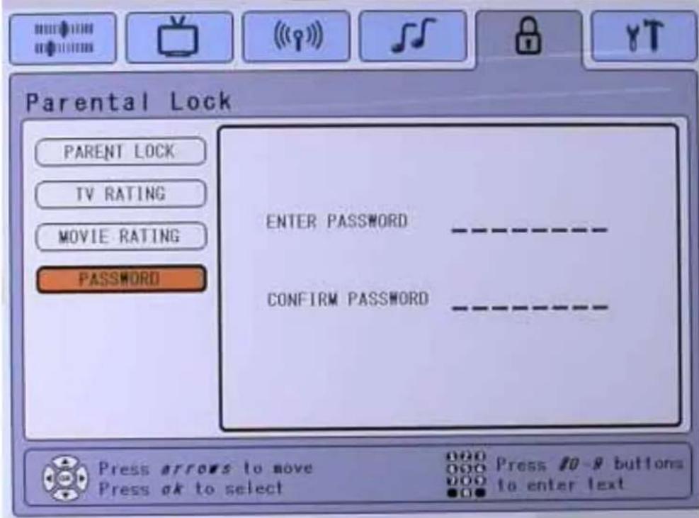
Password Page
- Move to Password Page and pressing OK shall invoke the selection
- Enter the new password and press OK.
- Reconfirm the new password and press OK.
• Completion of process shall exit the screen and save the new data. - Time out or MENU shall exit the OSD without saving any entered values.
NOTE: When you forget your password, please press [OK] + [SOURCES] + [MENU]+[RIGHT] to reset the system and set a new password again.
Function Explanation
PASSWORDS
Passwords are 8 Digits, and consist of numeric characters only entered in via the Remote Control only.
An entered password mismatch between the "NEW" Password and "CONFIRM PASSWORD" shall be rejected with an error message "Password not match".
Set Up Tab
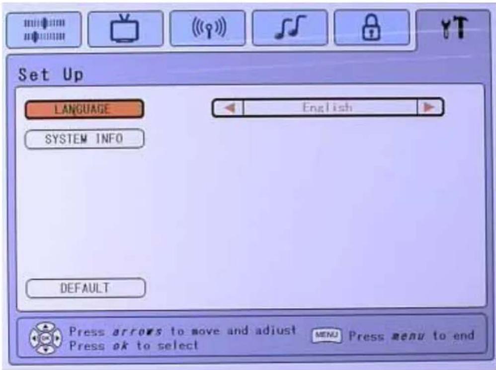
In the Set Up Tab, pressing OK then the functional page shall be displays.
Language Page
- Move ↑ and ↓ keys shall be used to navigate to the selection (Language, System info)
- Pressing OK shall invoke the selection
- and shall be used to change the selected bar's option (English, Spanish, etc.).
• Time out or MENU shall exit the OSD.
NOTE: Languages shall be defined by each region.
Function Explanation
LANGUAGE Shall select among available languages.
DEFAULT English is the default language.
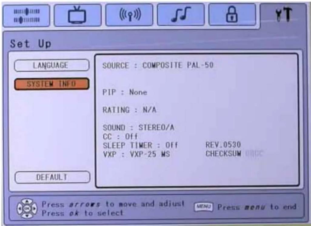
System Info Page
- This screen has no area for user operation, it is for informational purposes only and displays current system status information.
• Time out or MENU shall exit the OSD.
Function Explanation
SYSTEM INFO This screen shall display:
a. SOURCE: Active Source for which the main window is being displayed.
b. PIP Active Source. If no active PIP source this field shall return "NONE".
c. Rating: Should display the current program's rating. If none, display "N/A".
d. Audio Status. Valid values are "STEREO", "MONO", "SAP", or others depending on region.
e. CC: Closed Captioning Status. Valid Values "ON" or "OFF"
f. SLEEP TIMER: Either "OFF" or the Number of Minutes before shutdown.
g. VXP: Either "VXP 25", "VXP 10" if detected or "NONE" or "ERROR"
h. System version
Input sources
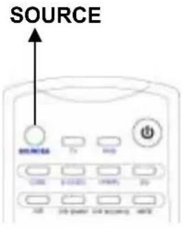
Press the SOURCE button via remote control to invoke the Audio Source Page. You can choose video input sources from VGA, DVI, YPbPr, TV and CVBS. If the image doesn't come in clearly, you may need to change the input signal type setting.
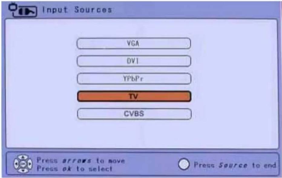
- ↑ and ↓ shall be used to navigate across the vertical items.
- Pressing OK shall invoke the selection.
• Time out or SOURCES shall exit the OSD.
Function Explanation
| VGA AN analog video source from computer input |
| DVI An digital video source from computer input |
| YPbPr A high resolution video input |
| TV For TV tuner connection. |
| CVBS For VCR or DVD player connection |
Audio Sources
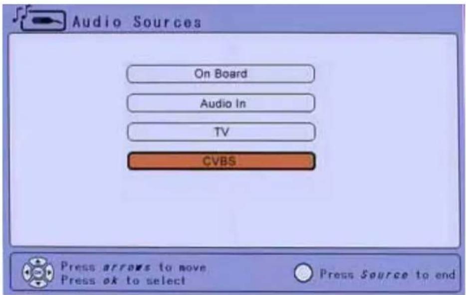
Press the AUDIO button via remote control to invoke the Audio Sources Page. You can choose audio input sources from On board, Audio in, TV and CVBS.
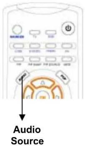
- ↑ and ↓ shall be used to navigate across the vertical items.
- Pressing OK shall invoke the selection.
• Time out or SOURCES shall exit the OSD.
Function Explanation
| ON BOARD Audio from PC |
| AUDIO IN Audio from HD Receiver or DVD player |
| TV TV audio |
| CVBS Audio from Video peripherals such as VCR, DVD player |
POP Screen
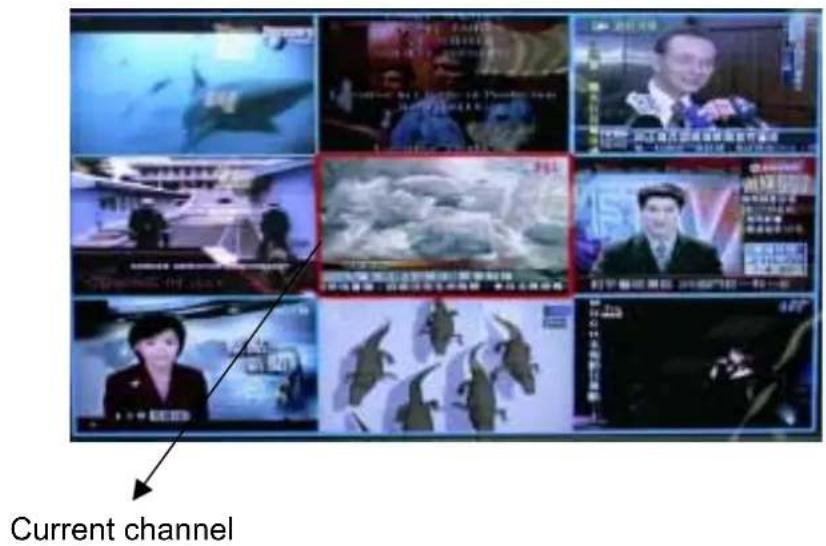
POP (picture outside picture) : Pressing POP button on the remote control to show additional pictures around on the screen that include current, go forward 4 channels and afterward 4 channels.
Other Information
Specifications
| LCD | Type | 27" (full 27" viewable diagonal area), TFT (Thin Film Transistor), Active Matrix WXGA LCD, 1280*720 RGB vertical stripe |
| Color Filter | Anti-Glare | |
| Viewing angles | Horizontal | +/- 85 |
| Vertical | +/- 85 | |
| Input signal | Video Sync | RGB analog or digital DVISeparate Sync f_h :30-82 kHz, fv:50-75 Hz |
| Compatibility | PC | Up to 1280 x 768 Non-interlaced (1280*720 preferred) |
| Macintosh | Power Macintosh up to 1280 x 768(1280*720 preferred) | |
| Resolution | Supported | 640x350 @ 70, 85Hz640x400 @ 70, 85Hz720x400 @ 70, 85Hz640x480 @ 60,75Hz800x600 @ 60,75Hz832x624 @ 60,75Hz1024x768@ 43i, 60,75 Hz1280x720 @ 60, 75 Hz |
| Recommended | 1280x720 @ 60, 75 Hz | |
| Power | Voltage | 100-240 VAC, 50/60 Hz (auto switch), 19V DC, 9.5A |
| Operating conditions | Temperature | 32° F to + 104° F (0° C to + 40° C) |
| Humidity | 10% to 90% (no condensation) | |
| Altitude | To 10,000 feet | |
| Storage conditions | Temperature | -4° F to + 140° F (-20° C to + 60° C) |
| Humidity | 10% to 90% (no condensation) | |
| Altitude | To 40,000 feet | |
| Dimensions | Physical | 786 mm (W) x 225 mm (H) x 526 mm (D)31" (W) x 8.9" (H) x 20.7" (D) |
| Weight | Net | 30.8 lb (14.0 kgs) |
| Regulations | cULus, TUV/GS, CB Report, CE, FCC-B, CCC, BSMI, GOST-R, PCBC, C-Tick, NOM, PSB, SASO | |
| Power saving modes | On | Normal |
| Active Off | <5W |
Compatibility
Suitable resolution for PC mode
| RESOLUTION Frequency | |
| 640x350 | 70Hz |
| 85Hz | |
| 640x400 | 70Hz |
| 85Hz | |
| 720x400 | 70Hz |
| 85Hz | |
| 60Hz | |
| 640x480 | 75Hz |
| 800x600 | 60Hz |
| 75Hz | |
| 832x624 | 60Hz |
| 75Hz | |
| 1024x768 | 43iHz |
| 60Hz | |
| 75Hz | |
| 1280x720 | 60Hz |
| 75Hz | |
| 1280x768 | 60Hz |
| 75Hz | |
Compatible SDTV/HDTV Modes:
| RESOLUTION Frequency | |
| 480i(30fps) | |
| 480P (60fps) (60Hz) | |
| 720P (60fps) (59 Hz) | |
| 1080i (30fps) | |
Compatible Video Formats on NTSC/PAL/SECAM Modes:
| Video Format | RF RGB DVI CVBS | SVHS | YPbPr/YCbCr | |||
| NTSC | VXP25 Yes Yes Yes | Yes Yes | ||||
| VXP10 Yes Yes Yes | No Yes | |||||
| PAL | VXP25 Yes Yes Yes | Yes Yes | ||||
| VXP10 Yes Yes Yes | No Yes | |||||
| SECAM | VXP25 Yes Yes Yes | Yes Yes | ||||
| VXP10 Yes Yes Yes | No Yes | |||||
Available Functions Related to Image Source
(# The function is available if PAL is detected)
(* it can not work for VXP 10), (! depend on resolution)
| RGB | DVI | YPbPr | TV | CVBS | |
| Picture Adjustment | V V V | V V | |||
| PICTURE | V V V | V V | |||
| Contrast | V V V | V V | |||
| Brightness | V V V | V V | |||
| Backlight | V V V | V V | |||
| Saturation | V V V | V V | |||
| Sharpness | V! V! | V V V | |||
| Hue | V V V | V V | |||
| COLOR | V V V | V V | |||
| LCD ADJUST | V V V | V V | |||
| H Size | V - - - | - | |||
| H Position | V - - - | - | |||
| V Position | V - - - | - | |||
| Fine Tune | V - V | - | |||
| Smooth | - - V | - | |||
| Auto Sync | V - - - | - | |||
| Display Adjustment | V V V | V V | |||
| SCALE MODE | V V V | V V | |||
| PIP SOURCE | V V V | V V | |||
| SLEEP | V V V | V V | |||
| CAPTIONS | V V V | V V | |||
| Tuner Setting | V* V* | V* V* V* | |||
| TUNER INPUT | V* V* | V* V* V* | |||
| AUTO SCAN | V* V* | V* V* V* | |||
| EDIT CHAN. | V* V* | V* V* V* | |||
| CHAN. LABEL | V* V* | V* V* V* | |||
| MANUAL SETUP | - - - - # | - | |||
| Channel | - - - - # | - | |||
| Air System | - - - - # | - | |||
| Search | - - - - # | - | |||
| Save | - - - - # | - | |||
| Audio Settings | V V V | V V | |||
| BASS | V V V | V V | |||
| TREBLE | V V V | V V | |||
| BALANCE | V V V | V V | |||
| MTS | V V V | V V | |||
| AUDIO SELECT | V V V | V V | |||
| AUDIO SOURCE | V V V | V V | |||
| Parental Lock | V V V | V V | |||
| PARENT LOCK | V V V | V V | |||
| TV RATING | V V V | V V | |||
| MOVIE RATING | V V V | V V | |||
| PASSWORD | V V V | V V | |||
| Set up | V V V | V V | |||
| LANGUAGE | V V V | V V | |||
| SYSTEM INFO | V V V | V V |
Troubleshooting
No power
• Make sure power button (or switch) is ON.
- Make sure A/C power cord is securely connected to the DC power supply and the power supply is firmly connected to the LCD TV.
- Plug another electrical device (like a radio) into the power outlet to verify that the outlet is supplying proper voltage.
Power is ON but no screen image
- Make sure the video cable supplied with the LCD TV is tightly secured to the video output port on the back of the computer. If the other end of the video cable is not attached permanently to the LCD TV, tightly secure it to the NextVision LCD TV.
- Adjust brightness and contrast.
- If you are using an Macintosh older than G3, you need a Macintosh adapter.
Wrong or abnormal colors
- If any colors (red, green, or blue) are missing, check the video cable to make sure it is securely connected. Loose or broken pins in the cable connector could cause an improper connection.
- Connect the LCD TV to another computer.
Control buttons do not work
- Press only one button at a time.
VXP problems
- The VXP adapter must be plugged in when the LCD TV is turned on. It is not "hot-pluggable".
Forget password
- When you forget your password, please press [OK] + [SOURCES] + [MENU]+[RIGHT] to reset the system.
Customer Support
For technical support or product service, see the table below or contact your reseller.
[NOTE]: You will need the product serial number.
| Country/Region | Web site T = TelephoneF = FAX | |
| United States | viewsonic.com/support | T: (800) 688-6688F: (909) 468-1202 |
| Canada | viewsonic.com/support | T: (800) 688-6688F: (909) 468-1202 |
| United Kingdom | viewsoniceurope.com | T: 0800 833 648F: (01293) 643910 |
| Europe, Middle, East, Baltic, countries, and North Africa | viewsoniceurope.com | Contact your reseller |
| Australia and New Zealand | viewson ic.com.au | T: +61 2 9929 3955F: +61 2 9929 8393 |
| Singapore/India and Southeast Asia | viewsonic.com.sg | T: 65 273 4018F: 65 273 1566 |
| Other Asia/Pacific countries | viewsonic.com.tw | T: 886 2 2246 3456F: 886 2 8242 3668 |
| South Africa | viewsonic.com/asia | T: 886 2 2246 3456F: 886 2 8242 3668 |
Cleaning the LCD TV
• MAKE SURE THE LCD TV IS TURNED OFF.
• NEVER APPLY ANY LIQUID DIRECTLY ONTO THE SCREEN OR CASE.
To clean the screen:
- Wipe the screen with a clean, soft, lint-free cloth. This removes dust and other particles.
- If still not clean, apply a small amount of non-ammonia, non-alcohol based glass cleaner onto a clean, soft, lint-free cloth, and wipe the screen.
To clean the case:
- Use a soft, dry cloth.
- If still not clean, apply a small amount of a non-ammonia, non-alcohol based, mild non-abrasive detergent onto a clean, soft, lint-free cloth, then wipe the surface.
Disclaimer
ViewSonic does not recommend the use of any ammonia or alcohol-based cleaners on the LCD TV screen or case. Some chemical cleaners have been reported to damage the screen and/or case of the LCD TV.
ViewSonic will not be liable for damage resulting from use of any ammonia or alcohol-based cleaners.
Limited Warranty
VIEWSONIC LCD Multimedia Display
What the warranty covers:
ViewSonic warrants its products to be free from defects in material and workmanship during the warranty period. If a product proves to be defective in material or workmanship during the warranty period, ViewSonic will, at its sole option, repair or replace the product with a like product. Replacement product or parts may include remanufactured or refurbished parts or components.
How long the warranty is effective:
ViewSonic® LCD displays are warranted for one (1) year for all parts including the light source and one (1) year for all labor from the date of the first consumer purchase.
Who the warranty protects:
This warranty is valid only for the first consumer purchaser.
What the warranty does not cover:
- Any product on which the serial number has been defaced, modified or removed.
-
Damage, deterioration or malfunction resulting from:
a. Accident, misuse, neglect, fire, water, lightning, or other acts of nature, unauthorized product modification, or failure to follow instructions supplied with the product.
b. Repair or attempted repair by anyone not authorized by ViewSonic.
c.Any damage of the product due to shipment.
d. Removal or installation of the product.
e.Causes external to the product, such as electrical power fluctuations or failure.
f. Use of supplies or parts not meeting ViewSonic's specifications.
g.Normal wear and tear.
h.Any other cause which does not relate to a product defect. -
Removal, installation, and set-up service charges.
How to get service:
- For information about receiving service under warranty, contact ViewSonic Customer Support. You will need to provide your product's serial number.
- To obtain service under warranty, you will be required to provide (a) the original dated sales slip, you're your name, (c) your address, (d) a description of the problem, and (e) the serial number of the product.
- Take or ship the product freight prepaid in the original container to an authorized ViewSonic service center or ViewSonic.
- For additional information or the name of the nearest ViewSonic service center, contact ViewSonic.
Limitation of implied warranties:
THERE ARE NO WARRANTIES, EXPRESS OR IMPLIED, WHICH EXTEND BEYOND THE DESCRIPTION CONTAINED HEREIN INCLUDING THE IMPLIED WARRANTY OF MERCHANTABILITY AND FITNESS FOR A PARTICULAR PURPOSE.
Exclusion of damages:
VIEWSONIC'S LIABILITY IS LIMITED TO THE COST OF REPAIR OR REPLACEMENT OF THE PRODUCT. VIEWSONIC SHALL NOT BE LIABLE FOR:
-
DAMAGE TO OTHER PROPERTY CAUSED BY ANY DEFECTS IN THE PRODUCT, DAMAGES BASED UPON INCONVENIENCE, LOSS OF USE OF THE PRODUCT, LOSS OF TIME, LOSS OF PROFITS, LOSS OF BUSINESS OPPORTUNITY, LOSS OF GOODWILL, INTERFERENCE WITH BUSINESS RELATIONSHIPS, OR OTHER COMMERCIAL LOSS, EVEN IF ADVISED OF THE POSSIBILITY OF SUCH DAMAGES.
-
ANY OTHER DAMAGES, WHETHER INCIDENTAL, CONSEQUENTIAL OR OTHERWISE.
-
ANY CLAIM AGAINST THE CUSTOMER BY ANY OTHER PARTY.
Effect of state law:
This warranty gives you specific legal rights, and you may also have other rights which vary from state to state. Some states do not allow limitations on implied warranties and/or do not allow the exclusion of incidental or consequential damages, so the above limitations and exclusions may not apply to you.
Sales outside the U.S.A. and Canada:
For warranty information and service on ViewSonic products sold outside of the U.S.A. and Canada, contact ViewSonic or your local ViewSonic dealer.
ViewSonic
LCD
MM
Warranty
(V1.0)
Release
Date:
12-17-
Appendix
Safety Guidelines
Warning: This device must be operated with the original power supply, part number: FSP180-1ADE11
CAUTION: The socket-outlet should be installed near the equipment and should be easily accessible.
CAUTION: Use a power cable that is properly grounded. Always use the appropriate AC cord that is certified for the individual country. Some examples are listed below:
| USA......UL | Switzerland .... SEV |
| Canada......CSA | Britain ...... BASE |
| Germany......VDE | Japan ...... PSE |
IMPORTANT NOTICE CONCERNING POWER CORD SELECTION
The power cord set for this unit has been enclosed and has been selected according to the country of destination and must be used to prevent electric shock. Use the following guidelines if it is necessary to replace the original cord set, or if the cord set is not enclosed.
The female receptacle of the cord set must meet EN-60320 requirements and may look like (Figure A1 below):

For the United States and Canada
In the United States and Canada the male plug is a NEMA5-15 style (Figure A2), UL Listed, and CSA Labeled. For units which are mounted on a desk or table, type SVT or SJT cord sets may be used. For units which sit on the floor, only SJT type cord sets may be used. The cord set must be selected according to the current rating for your unit. Please consult the table below for the selection criteria for power cords used in the United States and Canada.
| Cord Type $ize of Conductors in Cord Maximum Current Rating of Unit | |||
| SJT | 18 | AWG | 10 Amps |
| 16 AWG | 12 Amps | ||
| 14 AWG | 12 Amps | ||
| SVT | 18 | AWG | 10 Amps |
| 17 AWG | 12 Amps | ||
For European Countries
In Europe you must use a cord set which is appropriate for the receptacles in your country. The cord set is HARCertified, and a special mark that will appear on the outer sheath, or on the insulation of one of the inner conductors.
AC PLUG CORD PRECAUTIONS FOR THE UNITED KINGDOM
FOR YOUR SAFETY PLEASE READ THE FOLLOWING TEXT CAREFULLY.
IF THE FITTED MOULDED PLUG IS UNSUITABLE FOR THE SOCKET OUTLET THEN THE PLUG SHOULD BE CUT OFF AND DISPOSED OF SAFELY.
THERE IS A DANGER OF SEVERE ELECTRICAL SHOCK IF THE CUT OFF PLUG IS INSERTED INTO AN APPROPRIATE SOCKET.
If a new plug is to be fitted, please observe the wiring code as shown below.
If in any doubt, please consult a qualified electrician.
WARNING: THIS APPLIANCE MUST BE EARTHED.
IMPORTANT: The wires in this mains lead are coloured in accordance with the following code:
Green-and-Yellow: Earth
Blue: Neutral
Brown: Live
If the coloured wires of the mains lead of this appliance do not correspond with the coloured markings identifying the terminals in your plug, proceed as follows:
The wire which is coloured GREEN-AND-YELLOW must be connected to the terminal in the plug which is marked by the letter E or by the Earth symbol or coloured GREEN or GREEN-AND-YELLOW.
The wire which is coloured BLUE must be connected to the terminal in the plug which is marked with the letter N or coloured BLACK. The wire which is coloured BROWN must be connected to the terminal in the plug which is marked with the letter L or coloured RED.
If you have any questions concerning which proper power cord to use, please consult with the dealer from whom you have purchased the product.
Compliance Information for U.S.A.
This equipment has been tested and found to comply with the limits for a Class B digital device, pursuant to part 15 of the FCC Rules. These limits are designed to provide reasonable protection against harmful interference in a residential installation. This equipment generates, uses, and can radiate radio frequency energy, and if not installed and used in accordance with the instructions, may cause harmful interference to radio communications. However, there is no guarantee that interference will not occur in a particular installation. If this equipment does cause harmful interference to radio or television reception, which can be determined by turning the equipment off and on, the user is encouraged to try to correct the interference by one or more of the following measures:
• Reorient or relocate the receiving antenna.
- Increase the separation between the equipment and receiver.
- Connect the equipment into an outlet on a circuit different from that to which the receiver is connected
- Consult the dealer or an experienced radio/TV technician for help.
FCC Warning
To assure continued FCC compliance, the user must use grounded power supply cord and the provided shielded video interface cable with bonded ferrite cores. If a BNC cable is going to be used, use only a shielded BNC(5) cable. Also, any unauthorized changes or modifications not expressly approved by the party responsible for compliance could void the user's authority to operate this device.
CE Conformity for Europe

The device complies with the requirements of the EEC directive 89/336/EEC as
amended by 92/31/EEC and 93/68/EEC Art.5 with regard to "Electromagnetic
compatibility," and 73/23/EEC as amended by 93/68/EEC Art.13 with regard to "Safety."
ViewSonic Corporation

- NextVision™ Wide-Screen Entertainment Display
- Getting Started.... 12
- Main Menu Controls.... 19
- Other Information 42
- Appendix 49
- Product Registration
- For Your Records
- Product disposal at end of product life
- Installation
- Precautions
- Package Contents
- Quick Installation
- Remove one back panel cover
- Connect a (optional) TV tuner or Video Module.
- Connect VXP adapter to RF
- Connect AV
- 5.Audio Installation (optional)
- Connect power cord and AC/DC adapter
- Installation is almost complete, please re-attach the back panel. And follow the initial setup to get starting to watch TV or Video.
- Plug into AC power source (wall outlet)
- Installation with PC
- Remove rear panel cover
- Connect power cord and AC/DC adapter
- Connect video cable
- Turn ON LCD TV and computer
- Insert the ViewSonic Wizard CD into the computer's CD drive.
- Audio Installation (optional)
- Windows users: Set the timing mode to 1280 x 720 @ 60Hz
- Setting the Timing Mode (PC RGB Input)
- Choose a suitable video input sources for best image.
- Installation is complete. Enjoy your new ViewSonic, LCD TV.
- Getting Started
- Initial Setup
- Power on
- Set a language
- Input sources
- 4.Set Tuner Input
- NTSC system
- PAL system
- Auto-scan the TV channel
- Using the On Screen Display (OSD)
- Top Panel Shortcuts
- Remote Controls
- To adjust the screen image
- The following tips may help you optimize your LCD TV:
- Main Menu Controls
- Picture Adjustment Tab
- Picture Page
- Color Page
- LCD Adjust Page
- Display Adjustment Tab
- Function Explanation
- SCALE MODE
- PIP SOURCE
- Tuner Setting Tab
- Chan Label Page
- Manual Setup Page
- Audio Settings Tab
- Audio Settings Page
- Parental Lock Tab
- Parental Lock Page
- Explanation
- PARENTAL LOCK
- Parental Lock Warning Messages
- 1.Channel Lock
- 2.Incorrect Password
- 3.Channel Unlocked Confirmation
- TV Rating Page
- Movie Rating Page
- Password Page
- PASSWORDS
- Set Up Tab
- Language Page
- System Info Page
- Input sources
- Audio Sources
- POP Screen
- Other Information
- Compatibility
- Available Functions Related to Image Source
- Troubleshooting
- No power
- Power is ON but no screen image
- Wrong or abnormal colors
- Control buttons do not work
- VXP problems
- Forget password
- Customer Support
- Cleaning the LCD TV
- To clean the screen:
- To clean the case:
- Disclaimer
- Limited Warranty
- VIEWSONIC LCD Multimedia Display
- What the warranty covers:
- How long the warranty is effective:
- Who the warranty protects:
- What the warranty does not cover:
- How to get service:
- Limitation of implied warranties:
- Exclusion of damages:
- Effect of state law:
- Sales outside the U.S.A. and Canada:
- Appendix
- Safety Guidelines
- IMPORTANT NOTICE CONCERNING POWER CORD SELECTION
- For the United States and Canada
- For European Countries
- AC PLUG CORD PRECAUTIONS FOR THE UNITED KINGDOM
- Compliance Information for U.S.A.
- FCC Warning
- CE Conformity for Europe
Brand : VIEWSONIC
Model : VPW4255
Category : TV