
Wogglebug - Synthesizer Make Noise - Free user manual and instructions
Find the device manual for free Wogglebug Make Noise in PDF.


| Brand | Make Noise |
| Model | Wogglebug (Richter Wogglebug) |
| Product Type | Eurorack Synthesizer Module (Random Voltage Generator) |
| Width | 10 HP (approx. 2.0 in / 50.8 mm) |
| Depth | Not specified (typical Eurorack module depth ~30 mm) |
| Weight | Not specified (approx. 150 g) |
| Power Supply | +12V DC @ 50 mA, -12V DC @ 40 mA |
| Power Connector | Eurorack 16-pin ribbon cable (red stripe for -12V) |
| Audio Outputs | Smooth VCO (10Vpp, Shark's fin), Ring Mod (10Vpp, pulse), Woggle VCO (10Vpp, square) |
| CV Outputs | Stepped Random (10Vpp), Smooth CV (0-10V), Woggle CV (0-10V) |
| Gate/Clock Outputs | Burst Output (0-10V random gates), Clock Output (0-10V square) |
| Control Inputs | Ego Input (external S&H input, 10Vpp max), Influence Input (CV/audio, 0-10V), Speed CV Input (0-8V), External Clock Input |
| Panel Controls | Speed/Chaos, Ego/Id Balance, Woggle, Disturb Button, Speed/Chaos CV Attenuator, System Clock LED, Burst Activity LED, Internal Clock LED |
| Clock Range | Internal: 1 cycle per minute to ~200 Hz; External: any signal |
| Functions | Random voltage generation, Sample & Hold, Lag processing, Burst gate generation, Voltage-controlled VCOs, Digital ring modulation, Clock generation |
| Maintenance | Wipe with a dry cloth; avoid moisture and solvents |
| Safety | Disconnect power before installation; ensure correct polarity of ribbon cable |
| Warranty | 1 year from purchase (defects in materials/workmanship); contact Make Noise for RMA |
| Spare Parts & Repairability | Contact Make Noise support for service; typical module, repair possible by qualified technician |
| Included Accessories | Eurorack bus board connector cable, mounting screws (not listed but assumed) |
| Manual Language | English (manual available online) |
Frequently Asked Questions - Wogglebug Make Noise
User questions about Wogglebug Make Noise
0 question about this device. Answer the ones you know or ask your own.
Ask a new question about this device
Download the instructions for your Synthesizer in PDF format for free! Find your manual Wogglebug - Make Noise and take your electronic device back in hand. On this page are published all the documents necessary for the use of your device. Wogglebug by Make Noise.
USER MANUAL Wogglebug Make Noise
Make Noise warrants this product to be free of defects in materials or construction for a period of one year from the date of purchase (proof of purchase/invoice required).
Malfunction resulting from wrong power supply voltages, backwards or reversed eurorack bus board cable connection, abuse of the product or any other causes determined by Make Noise to be the fault of the user are not covered by this warranty, and normal service rates will apply.
During the warranty period, any defective products will be repaired or replaced, at the option of Make Noise, on a return-to-Make Noise basis with the customer paying the transit cost to Make Noise. Please contact technical@makenoisemusic.com for Return To Manufacturer Authorization.
Make Noise implies and accepts no responsibility for harm to person or apparatus caused through operation of this product.
Please contact technical@makenoisemusic.com with any questions, needs & comments, otherwise... go MAKE NOISE!
http://www.makenoisemusic.com
About This Manual:
Written by Tony Rolando Edited by Walker Farrell Illustrated by W.Lee Coleman
THANK YOU
Beta Analysts: Walker Farrell, Lee Coleman, Devin Booze, Richard Devine, Robert AA Lowe, Pete Speer
Special Thanks to Grant Richter for his genius and contributions to the world of synthesizers and for granting Make Noise permission to design a version of the Wogglebug!
Electrocution hazard!
Always turn the Eurorack case off and unplug the power cord before plugging or un-plugging any Eurorack bus board connection cable.
Do not touch any electrical terminals when attaching any Eurorack bus board cable.
The Make Noise Richter Wogglebug is an electronic music module requiring 50mA of +12VDC and 40 mA of -12VDC regulated voltages and a properly formatted distribution receptacle to operate. It must be properly installed into a Eurorack format modular synthesizer system case.
Go to http://www.makenoisemusic.com/ for examples of Eurorack Systems and Cases.
To install, find 10HP in your Eurorack synthesizer case, confirm proper installation of included eurorack bus board connector cable on backside of module (see picture below), plug the bus board connector cable into the Eurorack style bus board, minding the polarity so that the RED stripe on the cable is oriented to the NEGATIVE 12 Volt line on both the module and the bus board. On the Make Noise 6U or 3U Busboard, the negative 12 Volt line is indicated by the white stripe.

Please refer to your case manufacturers' specifications for location of the negative supply.
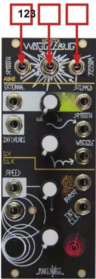
Audio:
- Smooth VCO Output: Shark's Fin wave audio rate signal controlled by the Ego Input, Ego/Id panel setting, Influence CV Input, and Speed/Chaos controls; 10Vpp.
- Ring-Mod Output: Pulse Wave Audio rate signal, ring modulated product of Smooth VCO, Woggle VCO and audio rate signal at the Influence Input (if present). It gets messy, real fast. The digital nature of the Ring-Mod circuit makes Simple waveforms (Pulse, Square, Triangle, Sine, Saw) almost necessary to achieve something remotely musical, but don't let that stop you from pumping Motown samples into this circuit! 10Vpp.
- Woggle VCO Output: Square Wave audio rate signal, controlled by Woggle panel control, Ego Input, Ego/Id Balance Control, Influence CV Input, and Clock Rate/Chaos controls; 10Vpp.

CV:
-
Ego/Id Balance Control: with nothing inserted at the Ego Input, sets the range of probable values. Turning this control CCW, the random values generated by the system tend to "cluster." With a signal applied to the Ego Input, it allows that external signal to be balanced with the internal signal source to generate random voltages.
-
Ego Input (external input for S&H): Signals applied here are injected directly to the uncertainty, beating heart of the Wogglebug. Accepts Control Voltages or Audio Rate signals; expects 10Vpp max.
-
Stepped Output: At lower Clock rates, the Stepped Random Voltage appears here: new value occurring at every clock pulse indicated by the blue System Clock LED. At higher (audio) clock rates, bit reduction effects may be achieved by inserting an audio signal into Ego Input and setting Ego/Id Balance full CCW; 10Vpp range.
-
Stepped Output Activity Window: visual indication of approximate Stepped Random Voltage value.
-
Influence Input: CV and/or Audio Signal input that performs the following duties: modulates frequency of SMOOTH and Woggle VCOs, inputs to the Ring-Mod circuit, and level shifts the Woggle CV signal. Responds 0V to 10V.
-
SMOOTH OUT: Smooth Control Voltage appears here, the smoothness of which is set by the Speed/Chaos Control; 0V to 10V.
-
Woggle Control: Sets how quickly (or slowly) the Woggle circuit is able to catch the Smooth/Stepped circuit. Clockwise slows the Woggle CV, counterclockwise speeds it up.
-
Woggle CV OUT: A of product of the Smooth/ Stepped CV, this voltage quivers, shakes, and chases after the heart of the system... always, and is smoothed by the Woggle panel control; 0V to 10V.
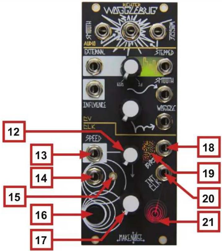
Panel Controls: (cont'd)
CLK:
-
Speed/Chaos CV Attenuator: unipolar attenuator for Speed CV Input. Normalled to 8V (see below).
-
Speed/Chaos CV Input: unipolar control signal input for Speed parameter. Normalled to +8V so that with nothing patched, the associated Speed CV attenuator will extend the internal clock generator range up to around 200hz; Range: 0V to +8V.
-
External Clock Input: any signal may be applied here, allowing for independent control of rate and smoothness.
-
System Clock LED: Displays rate of Sample and Hold clock. When a signal is applied to the External Clock Input, shows the rate of the incoming clock/rising edge. With nothing patched, mirrors the Internal clock.
-
Disturb Button: Direct control of the Sample and Hold circuit: pressing Samples; holding Holds.
-
Speed/Chaos Control: dual purpose control that sets the Rate of the Wogglebug Internal Clock generator & the lag processor feeding the Smooth CV circuit. Turning it CCW slows the system and smoothes its response. Turning it CW quickens the system with the Smooth CV response becoming jittery. Internal Clock generator range is 1 minute per cycle up to around 40hz (extended range pushes upper limit to around 200hz).
-
Burst Output: Square random gate signal, synced to the Clock and influenced by the Stepped, Smooth, and Woggle controls; 0 to +10V.
-
Burst Output Activity Window: Visual representation of random gates.
-
Clock Output: Square clock signal from the internal clock generator. Not influenced by signal at External Clock Input; 0V to +10V.
-
Internal clock LED: Displays rate of internal clock. NOT affected by External Clock Input.
Amongst other things, the Make Noise Wogglebug contains the following: 1 Voltage-Controlled Clock, 1 Sample & Hold, 2 Lag Processors, 1 Random Gate Burst Generator, and 2 VCO Digital Ring Mod: most of which are patchable via the instrument's panel in a system that is capable of CV and Audio Signal generation and processing.
While we have broken the Panel Controls & I/O description into Sections for explanation, please understand that ALL portions of the Wogglebug interact with each other. For example, changing the Ego/Id Balance will affect the Stepped, SMOOTH, and Woggle CVs, the SMOOTH VCO, Ring-Mod and Woggle VCO OUTs! The way that we like to think of the system is that the Woggle Circuit is chasing the SMOOTH/Stepped Circuit, which is being kicked in the ass by the Internal Clock. It is very possible to make patches and panel settings which lock up the Wogglebug, and thus the CV outputs will hang at the last voltage level while the VCOs will drone on almost unchanging. When this happens, adjusting just about any panel control will disturb and wake the Wogglebug. Finally, consider that many changes in the system are NOT immediate. This is because the Wogglebug is a complex feedback system where several sub-circuits are responding to each other.
IS THE WOGGLEBUG MY SYNTHESIZER'S ID MONSTER? SHOULD I BEWARE OF THE WOGGLEBUG? YES and maybe.
The Wogglebug is a random voltage generator, originally designed by Grant Richter of Wiard Synthesizers. The Wogglebug's purpose is to overtake the control voltages produced by your keyboard or sequencer during performance and give a voice to your synthesizer's ID. It is your synthesizer's ID MONSTER. A continuation of the Smooth and Stepped, fluctuating, Random Voltage Sources, pioneered by Don Buchla, the core of the circuit is based on the Buchla Model 265 "Source of Uncertainty" module, which many consider to be the most musical of all random voltage generators. Like the 265, the Wogglebug utilizes a lag processor (low frequency smoothing filter), a VCO, and a Sample & Hold in order to produce Stepped and Smooth (or lagged, slewed) Control Voltages in the range of 0 to 10 volts.
Grant's Wogglebug design expands on this system to include the otherworldly Woggle CVs (stepped voltages with decaying sinusoids at the edges), which must be heard in action to be truly appreciated. In a moment of considerable noise, Richter decided to tap into the sound sources at the uncertainly beating heart of the Wogglebug and bring them forth to the instrument's panel. He then figured a clever way to Ring Modulate these sounds and that too is on the panel of all Wogglebugs. Thus, the Wogglebug is a complete system: no external modules are required to Woggle; however, all voltage-controlled systems long to be tickled, bitten, plagued, and eventually, destroyed by the Wogglebug.
Tony fell in love with Grant's #3 circuit the moment his first Wogglebug came to life on an experimenter's breadboard. He built a few DIY Wogglebug #3, including the Ryan Williams designed clone PCB and was lucky enough to have used the Wiard Wogglebug #5 extensively. Now, we at Make Noise feel honored to be presenting this circuit as a Make Noise module.
The Make Noise Wogglebug is neither version #3 nor #5. In the truest spirit of Grant Richter, the Make Noise Wogglebug is not a clone. Instead, it is a tribute to all that Woggles and is an evolution of the original Richter design. Like the #3, the Make Noise Wogglebug is a single system; however, it improves upon the #3 by offering further functionality, such as an Influence Input to the Ring Mod circuit, the ability to directly inject a signal to the heart of the Wogglebug via the Ego Input, and a Random Gate Burst function: all of which have never appeared on any other Wogglebug. We also redesigned the Cluster circuit, and thus it has been renamed as Ego/Id Balance to reflect its further purposes, allowing for new functionality that has again, never existed with any other Wogglebug.
The new Richter Wogglebug has yet a few more tricks up its sleeve...
- A much more stable clock output with the widest frequency range yet seen on a Wogglebug. The clock now goes up to about 200Hz, allowing the Control Voltage and Gate Outputs to be heard directly as different flavors of analog and digital noise.
- In previous Wogglebugs, the clock had been locked to the internal Sample and Hold Circuit. Now, with the Richter Wogglebug, the clock can be freed by the independent External Clock Input or the Disturb Button. Regardless of what is happening at these control points, the Internal Clock Output will continue to run at the specified rate, keeping it open for use as a Master Clock at all times.
- The Disturb Button allows the Sample and Hold Circuit to be clocked manually: press to sample, hold to pause the CV outputs. When the Wogglebug is running fast, this can slow it down. When running slow or not at all, this kicks it in the ass and delivers the next set of random values.
- The Smooth VCO is a brand new waveform, Sharktooth.
- The Influence input has a greater effect on all parts of the Wogglebug's psyche than the previous Ring Mod input.
- The Burst output is more active and ALL portions of the Wogglebug are more responsive to control and touch.

Variation:
Try patching the Slewed version of the signal using the Wogglebug's Smooth CV Out, using MATHS EOR Gate to control the Sample Rate externally. Now the Clock Rate will set the Slew Rate independently of the Sample Rate.
Patch Example:
Pitch-to-Voltage (P.L.L.)
![graph TD A["Sequence from Rene's Qcv Output"] --> B["Woggle VCO "Follows" the Pitch of the DPO"] B --> C["Degree/Type of Following"] C --> D["Random Voltage that "Follows" the Pitch of the DPO"]](/content/2026/05/816908/images/90738ce25e47f96a8c007d553635e94f4f1bcc9bbbf0390a9f05fa9ab365ee70.jpg)
![graph TD A["Clock Rate"] --> B["Burst Rate"] B --> C["MODEL"] C --> D["PMBUS"] D --> E["MAX"] E --> F["MODBUS"] F --> G["MAX"] G --> H["LIMEL"] H --> I["OPTOMIX"] I --> J["LIMEL"] J --> K["OUT1"] K --> L["OUT2"] L --> M["LIMEL"] M --> N["OUT3"] N --> O["LIMEL"] O --> P["OUT4"] P --> Q["LIMEL"] Q -->…](/content/2026/05/816908/images/5b8949a4f0cb22661cfaee945b174345e819b42b760141beb5474ea903346641.jpg)
Patch Concept:
Patch Exciter
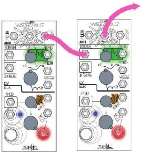
(Sound Source Not Depicted)
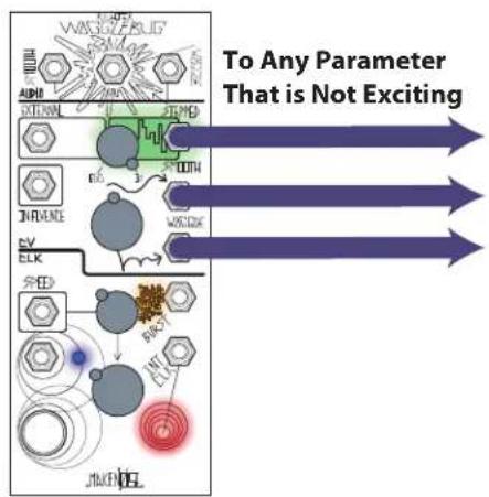
Patch Concept:
Dirty CV
(Sound Source Not Depicted)
![graph TD A["FUNCTION"] --> B["ENK"] B --> C["ENL"] C --> D["ENR"] D --> E["ENK"] E --> F["ENL"] F --> G["ENR"] G --> H["ENK"] H --> I["ENL"] I --> J["ENR"] J --> K["ENK"] K --> L["ENL"] L --> M["ENR"] M --> N["ENK"] N --> O["ENL"] O --> P["ENR"] P --> Q["ENK"] Q --> R["ENL"] R --> S["ENR"] S --> T["…](/content/2026/05/816908/images/5201bbdd20e396ca64922ef15e0920f9a3f9ad66836f44c76ee8af8feeac4516.jpg)
Patch Example:
Jittery Clock Concept
(Sound Source Not Depicted)

Variation:
For a Chaotic Clock, turn Speed Attenuator to about noon.
Patch Example:
Make Noise

Note:
Monitor any CV or Audio Output for different flavors of Noise.
Patch Example:
Lag Processor / Slew Limiter Concept (Sound Source Not Depicted)
![graph TD A["FUNCTION"] --> B["BRANS"] B --> C["PRESSURE PANTS"] C --> D["WASOLARUS"] D --> E["Slew Rate"] style A fill:#f9f,stroke:#333 style B fill:#ccf,stroke:#333 style C fill:#cfc,stroke:#333 style D fill:#fcc,stroke:#333 style E fill:#ffc,stroke:#333](/content/2026/05/816908/images/b25a8b2432c41dade85e85bfbb54432a6ac8bd1453c82464b327fc422c105c42.jpg)
Patch Concept:
Tame the Bug
(Sound Source Not Depicted)

Patch Concept:
Kick the Bug
(Sound Source Not Depicted)
![Attenuate at Destination(s) [PRESS]](/content/2026/05/816908/images/32c38241756c671681d3c1b9bfdbe138f4725f819e5b8e2a8505ad8011e8a01c.jpg)
Variation:
Turn the Speed Panel Control to 3 o'clock or greater. [PRESS] and [HOLD] the Disturb Button to "Kill" the Bug and the random voltages last generated will hang until release.
Patch Example: Bit Crush
![graph TD subgraph PhaO1 A["PHA O1"] --> B["ORI AMP"] B --> C["ORI AMP"] C --> D["ORI AMP"] D --> E["ORI AMP"] E --> F["ORI AMP"] F --> G["ORI AMP"] G --> H["ORI AMP"] H --> I["ORI AMP"] I --> J["ORI AMP"] J --> K["ORI AMP"] K --> L["ORI AMP"] L --> M["ORI AMP"] M --> N["ORI AMP"] N --> O["ORI AMP"]…](/content/2026/05/816908/images/5df8689b895c1dac8cf6c0d59c96ab1d9dda690e89d64c07543225d4fc6d7bdc.jpg)
Patch Example: Child Tones


Brand : Make Noise
Model : Wogglebug
Category : Synthesizer