
ES7001 - Loudspeaker MARANTZ - Free user manual and instructions
Find the device manual for free ES7001 MARANTZ in PDF.


| Product Type | Home Theater Speaker System |
| Brand | Marantz |
| Model | ES7001 |
| Dimensions (W x H x D) | 1080 x 153 x 144 mm |
| Weight | 12 kg |
| Power Supply | AC 230 V, 50/60 Hz |
| Power Consumption | 40 W (125 W max) |
| Standby Power | 0.8 W |
| Amplifier Type | 6-channel digital power amplifier |
| Virtual Surround Technology | OPSODIS (Optimal Source Distribution) |
| Decoding Formats | Dolby Digital, dts, AAC, PCM (32/44.1/48 kHz) |
| HDMI Version | 1.1 (2 inputs, 1 output) |
| Optical Digital Inputs | 3 (OPT IN 1/2/3) |
| Analog Audio Inputs | 2 (RCA stereo) |
| Subwoofer Output | 1 pre-out + 1 control out |
| Remote Control | RC002ES (with batteries) |
| Speaker Drivers | Tweeter 1.9 cm dome x2, Midrange 8 cm cone x2, Woofer 12 cm cone x2 |
| Cabinet Material | High-rigidity aluminum |
| Binaural Mode | Yes |
| Dolby Pro Logic II | Yes (Movie/Music/Off) |
| Night Mode | Yes (with Dolby Digital) |
| Auto Power-Off | Yes (after 5 min no signal) |
| Cleaning Instructions | Use soft lint-free cloth; mild detergent if needed |
| Warranty | Retain purchase receipt; contact local distributor |
Frequently Asked Questions - ES7001 MARANTZ
User questions about ES7001 MARANTZ
0 question about this device. Answer the ones you know or ask your own.
Ask a new question about this device
Download the instructions for your Loudspeaker in PDF format for free! Find your manual ES7001 - MARANTZ and take your electronic device back in hand. On this page are published all the documents necessary for the use of your device. ES7001 by MARANTZ.
USER MANUAL ES7001 MARANTZ
For warranty information, contact your local Marantz distributor.
RETAIN YOUR PURCHASE RECEIPT
Your purchase receipt is your permanent record of a valuable purchase. It should be kept in a safe place to be referred to as necessary for insurance purposes or when corresponding with Marantz.
IMPORTANT
When seeking warranty service, it is the responsibility of the consumer to establish proof and date of purchase. Your purchase receipt or invoice is adequate for such proof.
FOR U.K. ONLY
This undertaking is in addition to a consumer's statutory rights and does not affect those rights in any way.
FRANÇAIS
GARANTIE
The ES7001 is in conformity with the EMC directive and low-voltage directive.
€ Français
- Do not expose the equipment to rain, moisture, dripping or splashing.
- Do not remove the cover from the equipment.
- Do not insert anything into the equipment through the ventilation holes.
- Do not handle the mains cord with wet hands.
- Do not cover the ventilation with any items such as tablecloths, newspapers, curtains, etc.
- No naked flame sources, such as lighted candles, should be placed on the equipment.
- When disposing of used batteries, please comply with governmental regulations or environmental public instruction's rules that apply in your country or area.
- No objects filled with liquids, such as vases, shall be placed on the equipment.
- When the switch is in the OFF position, the equipment is not completely switched off from MAINS.
- The equipment shall be installed near the power supply so that the power supply is easily accessible.
- Do not expose the unit to excessive heat such as direct sunlight, fire or the like.
Français
AVERTISSEMENTS
Thank you for purchasing the Marantz Home Theater System.
Before using this unit, please read the User Guide carefully to ensure proper operation of the unit, and retain it together with the supplied warranty.
■ Accessories Check
Before use, check the below accessories were included in the package.
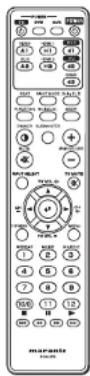
- Remote controller
- AAA-size batteries x 2
- User Guide (This manual)
A NOTE ABOUT RECYCLING

This product's packaging materials are recyclable and can be reused. This product and the accessories packed together are the applicable product to the WEEE directive except batteries.
Please dispose of any materials in accordance with your local recycling regulations.
When discarding the unit, comply with your local rules or regulations.
Batteries should never be thrown away or incinerated but disposed of in accordance with your local regulations concerning chemical wastes.
CONTENTS
FEATURES 2
BEFORE USING THIS UNIT 3
NAMES AND FUNCTIONS OF PARTS 5
FRONT PANEL 5
REAR PANEL 6
REMOTE CONTROLLER: RC002ES 7
CONNECTIONS....12
CONNECTING DIGITAL EQUIPMENT WITH THE OPTICAL CONNECTOR .... 12
CONNECTING ANALOG EQUIPMENT 13
CONNECTING DIGITAL EQUIPMENT EQUIPPED WITH THE HDMI
CONNECTOR....13
CONNECTING A SUBWOOFER 14
REMOTE CONTROL CONNECTIONS 14
INSTALLATION....15
BASIC OPERATIONS 16
TURNING ON THE UNIT 16
PLAYING THE INPUT SOURCE 16
SETTINGS 17
SETTING INSTALLATION HEIGHT OF SPEAKERS 17
SETTING THE NUMBER OF AUDIENCE 17
SETTING THE VIEWING/LISTENING DISTANCE 18
SETTING THE SUBWOOFER OUTPUT 18
SETTING THE BINAURAL MODE 19
SETTING THE DOLBY PRO LOGIC II MODE 19
SETTING MULTI-CHANNEL TV SOUND MODE 20
SETTING THE NIGHT MODE 20
SETTING THE DIMMER 20
RESETTING ITEMS TO FACTORY PRESET SETTINGS 21
TROUBLESHOOTING 21
SPECIFICATIONS 22
OTHERS 22
FEATURES
[MAIN FUNCTION]
● What is OPSODIS?
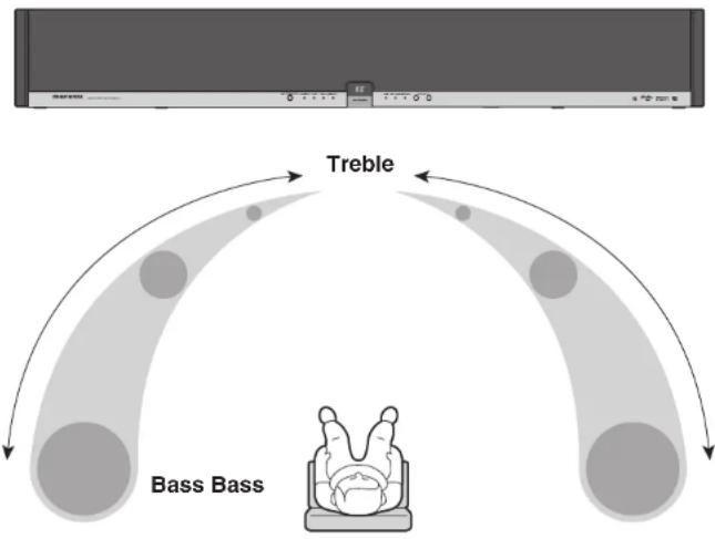
OPSODIS (Optimal Source Distribution) is a new virtual surround technology developed by the Institute of Sound and Vibration Research (ISVR) and Kajima Corporation.
OPSODIS technology has been united with Marantz's high-quality sound technology to realize a superior surround environment than ever before.
The ES7001 realizes reproduction of omni-directional sound only with the speakers built in this unit.
The ES7001 releases listeners from the conventional surround environment that has required complex installation of five or more speakers. As a result, installing the AV system in a room has little effect on their lifestyle or living environment.
[DIGITAL AMPLIFIER SECTION]
The unit incorporates a 6-channel digital power amplifier, allowing direct drive of the speakers' tweeter, midrange and woofer.
The digital audio signals are input to the digital amplifier of the unit through the optical digital and the HDMI connectors without digital-analog conversion.
[PWM PROCESSOR SECTION]
Using digital filters for cutoff frequency of the 6 channel digital power amplifier enables extreme filter precision that cannot be achieved with conventional analog filters, providing the OPSODIS effects more efficiently.
[POWER SUPPLY SECTION]
The R-core transformer is adopted for the power supply section of this unit. Thanks to the features of the R-core transformer—less leakage magnetic flux, less heat generation and quick response to overload variation—the unit produces a high quality and powerful sound.
[CABINET]
Adoption of high-rigidity aluminum for the cabinet of the unit provides a sophisticated stiff construction, allowing reproduction of beautiful crystalline sound.
[OTHER FEATURES]
● The OPT IN and HDMI IN connectors are compatible with Dolby Digital 5.1ch, dts and AAC audio inputs.
● Supports Dolby PL II feature for 2-channel signal input and for digital signal input.
- Binaural recording* sources can be reproduced through the front speaker.
* Binaural recording is a method of recording audio which uses two microphones mounted in the ears of a dummy head in the shape of the human head and ears.
Binaural recording can reproduce location of sound behind, ahead, above and below. It makes you feel a real sense of distance.
Normally, a dramatic binaural effect can be achieved only with headphones.
However, a similar or more stereophonic effect can be achieved by playback of a binaural recording source using this unit than that with headphones.
● The newest 32 bit DSP circuits adopted (one for decoding of Dolby, dts, ACC and PCM, and two dedicated for OPSODIS circuits)
FEATURES
● DOLBY
DO DOLBY
DIGITAL
Manufactured under license from Dolby Laboratories. "Dolby", "Pro Logic", the double-D symbol and "AAC" are trademarks of Dolby Laboratories.
AAC

AAC is a format of the MPEG2 standard. This features excellent high-compression encoding and high-quality sound, enabling reproduction of 2-channel stereo sound and 5.1-channel surround, and bilingual broadcast. The following is the patent numbers of this format.
5848391 5,291,557 5,451,954
5 400 433 5,222,189 5,357,594
5 752 225 5,394,473 5,583,962
5,274,740 5,633,981 5 297 236
4,914,701 5,235,671 07/640,550
5,579,430 08/678,666 98/03037
97/02875 97/02874 98/03036
5,227,788 5,285,498 5,481,614
5,592,584 5,781,888 08/039,478
08/211,547 5,703,999 08/557
08/894,844 5,299,238 5,299,239
5,299,240 5,197,087 5,490,170
5,264,846 5,268,685 5,375,189
5,581,654 5,548,574 5,717,821
08/937,950 05-183,988 08/506,729
08/576,495 08/392,756
● dts


Virtual
Manufactured under license under U.S. Patent No's: 5,451,942; 5,956,674; 5,974,380; 5,978,762; 6,487,535 & other U.S. and worldwide patents issued & pending. DTS is a registered trademark and the DTS logos, Symbol and DTS Virtual are trademarks of DTS, Inc. © 1996-2007 DTS, Inc. All Rights Reserved.
● OPSODIS

OPSODIS™
OPSODIS is a registered trademark of the OPSODIS LTD.
HDMI

HDMI, the HMI High-Definition
Multimedia Interface are trademarks or registered trademarks of HDMI Licensing LLC.
6
[Non-Text]
BEFORE USING
This section must be read before any connection is made to the mains supply.
■ Equipment mains working setting
Your Marantz product has been prepared to comply with the household power and safety requirements that exist in your area.
This unit can be powered by 120V AC only.
Copyright
Recording and playback of any material may require consent. For further information refer to the following:
– Copyright Act 1956
– Dramatic and Musical Performers Act 1958
– Performers Protection Acts 1963 and 1972
– Any subsequent statutory enactments and orders
■ Do Not Locate in the Following Places
To ensure long-lasting use, do not locate the unit where:
- Exposed to direct sunlight.
• Near to sources of heat such as heaters.
• Highly humid or poorly ventilated. - Dusty.
- Subjected to mechanical vibrations.
- On wobbly, inclined or otherwise unstable surfaces
- On a high place such as on a TV set
The ventilation holes are located at the rear of the unit. To ensure proper heat radiation, ensure the below clearance from walls and other equipment.
■ Keep Objects Off
Keep objects off the unit.
■ Do not touch hot spots during and immediately after use
During and immediately after use, the unit is hot in areas other than the controls and rear panel connection jacks. Do not touch hot spots and especially the rear panel. Contact with hot areas can cause burns.
■ Cautions on handling power cord
- Do not touch the power cord with wet hands.
- When disconnecting the power cord, always make sure that you take hold of the plug. Yanking out or bending the cord can damage it and/or cause electric shocks or a fire.
- Get into the habit of disconnecting the power plug before leaving home.
BEFORE USING
■ For use of Remote controller
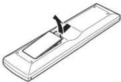
- Loading batteries
Before using the remote controller for the first time, load the batteries in the remote controller. The batteries provided are used to verify the operations of the remote controller only.
① Remove the battery cover.
natural_image
Line drawing of a remote control box with a handle and ventilation slots (no text or symbols)② Insert the batteries with correct +/- orientation.
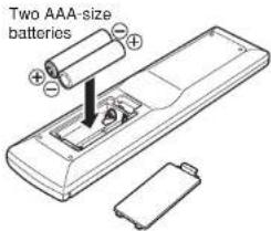
③ Close the battery cover until it clicks shut.
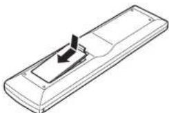
natural_image
Line drawing of a remote control casing with an arrow indicating left motion (no text or symbols)● Cautions on handling batteries
Misuse of the batteries can result in electrolyte leakage, rupturing, corrosion, etc.
Bear in mind the following points when using batteries.
- Remove the batteries from the remote controller if the unit is not going to be used for a prolonged period (a month or more).
- Do not use an old battery together with a new one.
- Insert the batteries while ensuring that their and poles are properly aligned with the corresponding markings on the remote controller.
- Batteries with the same shape may have different voltages. Do not use different types of batteries together.
- If electrolyte has leaked, thoroughly wipe the inside of the battery compartment, and then insert new batteries.
- When batteries which are no longer required are to be discarded, follow the directions (regulations) laid down by the local authorities in the area concerned for their disposal.
● Operatable range of Remote controller
Operate the unit with the remote controller within the range of the illustration below.
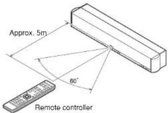
Cautions:
- Do not allow direct sunlight, an inverter fluorescent light or other strong source of light to shine onto the player's infrared receptor window. Otherwise, the operation of the remote controller may be disabled.
- Bear in mind that operating the remote controller may cause other devices operated by infrared rays to be operated by mistake.
- The remote controller cannot be operated if the space between the controller and the player's infrared receptor window is obstructed.
- Do not place any objects on top of the remote controller.
Doing so may cause one or more buttons to be held down which will cause the batteries to run down.
NAMES AND FUNCTIONS OF PARTS
FRONT PANEL
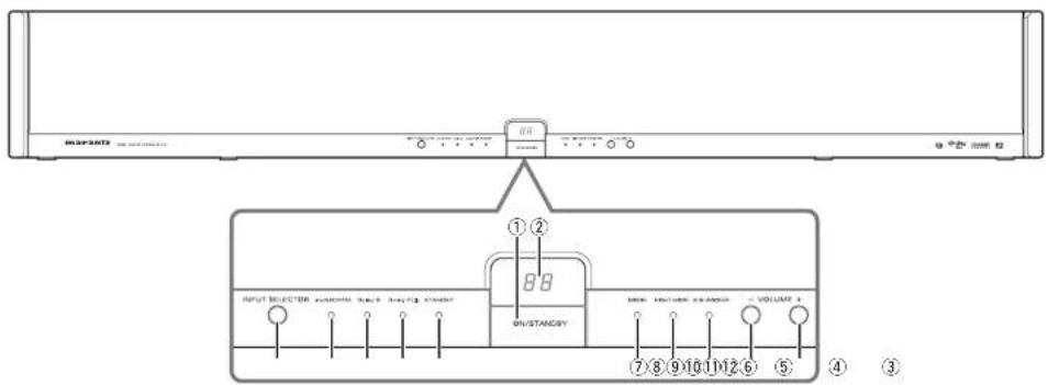
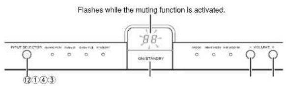
① ON/STANDBY button
Press this button to turn on the power. When it is pressed again, the unit goes into standby mode and the STANDBY indicator ⑧ lights.
② Display window
Normally, the volume level indication (00-60) is displayed.
③ VOLUME + button
Press this button to increase the volume. Keeping this button pressed increases the volume successively.
④ VOLUME - button
Press this button to decrease the volume. Keeping this button pressed decreases the volume successively.
⑤ SUB WOOFER Indicator
The indicator lights in green when subwoofer output is activated by pressing the SUBWOOFER button on the remote controller.
The indicator goes out when subwoofer output is set to off by pressing the SUBWOOFER button on the remote controller.
The subwoofer output is set to on and the indicator is lit as the factory-setting mode.
Note:
Before installing this unit, connect a commercially available or optional Marantz subwoofer with a built-in amplifier.
⑥ NIGHT MODE indicator
The indicator lights in green when the night mode function is activated.
The indicator goes out when the night mode function is canceled by pressing the NIGHT MODE button on the remote controller.
Note:
The night mode function can be activated only when the Dolby D (Digital) indicator is lit blue.
⑦ MODE indicator
The indicator lights in blue when the binaural mode is activated. The indicator goes out when the binaural mode is canceled by pressing the MODE button on the remote controller.
Note:
The binaural mode can be set when an audio source recorded in binaural mode is played.
⑧ STANDBY indicator
The indicator lights in red when the unit is in standby mode.
⑨ Dolby PL II indicator
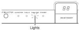
The indicator lights in green when 2-channel signal is input and the Dolby Pro Logic II mode is set to Pro Logic II MOVIE or Pro Logic II MUSIC.
When Dolby Pro Logic II mode is set to OFF by pressing the Dolby PL II button on the remote controller, this indicator goes out.
⑩ Dolby D indicator
When a Dolby digital signal is input, this indicator lights in blue.
⑪ dts/AAC/PCM indicator
The indicator lights in the following colors according to the format of digital signal input from the connected equipment:
dts signal: red
AAC signal: yellow
PCM signal: green
The indicator goes out when the A1 or A2 button on the remote controller is pressed to select an analog input signal.
⑫ INPUT SELECTOR button
Press this button to select the input source to be played.
Each press of the button changes the indication in the display window as shown below.
The factory-preset setting is "d1."
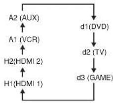
flowchart
graph TD
    A["A2 (AUX)"] --> D["d1(DVD)"]
    B["A1 (VCR)"] --> A
    C["H2(HDMI 2)"] --> A
    D --> E["d2 (TV)"]
    E --> F["d3 (GAME)"]
    F --> G
    G --> H["H1(HDMI 1)"]
    H --> A
NAMES AND FUNCTIONS OF PARTS
REAR PANEL
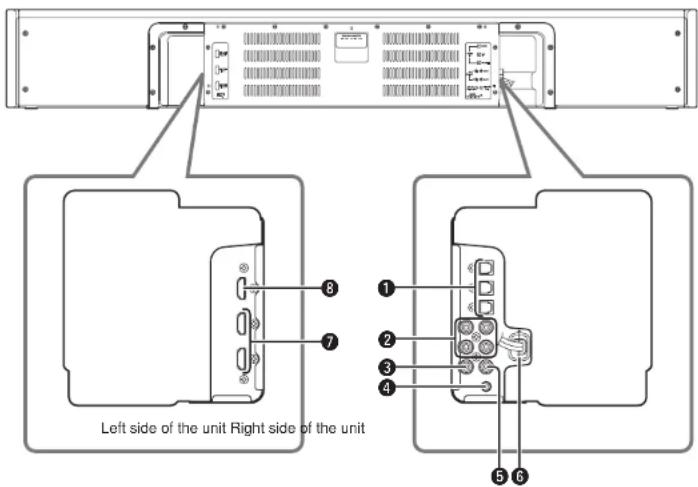
① OPT IN 1 (DVD)/2 (TV)/3 (GAME)
connectors
These connectors are used to connect to the optical digital output connectors on a DVD player, TV, video game console, etc.
- Connect a DVD player to the OPT IN 1 connector.
- Connect a TV to the OPT IN 2 connector.
- Connect a video game console to the OPT IN 3 connector.
Note:
When "d1", "d2" or "d3" is selected with the INPUT SELECTOR button on the unit and no signal is input from the connected equipment for five minutes, the unit automatically goes into standby mode.
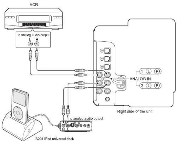
② ANALOG IN 1 (VCR)/2 (AUX) Jacks
These jacks are used to connect to the analog output jacks on a VCR and external player.
- Connect a VCR to the ANALOG IN 1 jacks. To select the input, press the A1 button on the remote controller.
- Connect an external player to the ANALOG IN 2 jacks. To select the input, press the A2 button on the remote controller.
③ SUB W. PREOUT jack
This jack is used to connect to the input jack of an external subwoofer with a built-in amplifier.
④ SUB W. CONTROL OUT jack
This jack is used to connect to the CONTROL IN jack of the optional Marantz SW7001 subwoofer with built-in amplifier. The connected subwoofer is turned on or goes into standby mode in conjunction with the operations of the unit.
Note:
To use the control function, turn on the power of the subwoofer.
⑤ REMOTE OUT Jack
This jack is used to connect other Marantz equipment such as a DVD player equipped with remote control jack.
Note:
When the Marantz DVD player or the IS201 iPod universal dock is located in a place where the infrared beam cannot be easily received, make a remote control connection. If you operate the remote controller pointed toward this unit, a received command signal is transmitted to the connected equipment.
⑥ AC power cord
Connect the cord to the wall outlet.
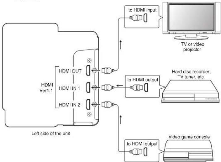
⑦ HDMI IN 1/2 connectors
These connectors are used to connect to the HDMI output of a hard disk recorder, TV tuner, video game console, etc. The HDMI IN/OUT connectors on the unit are compatible with Version 1.1.
⑧ HDMI OUT connector
This connector is used to connect to the HDMI input of a TV, video projector, etc. The HDMI IN/OUT connectors on the unit are compatible with Version 1.1.
Note:
The audio input to the HDMI jacks can be played back by this unit. In such case, audio signals are not output to the TV or projector.
NAMES AND FUNCTIONS OF PARTS
REMOTE CONTROLLER: RC002ES
■ Buttons used for this unit
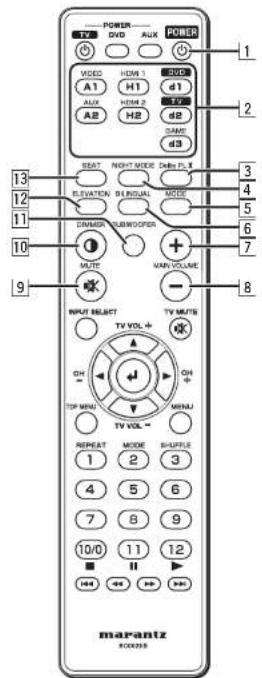
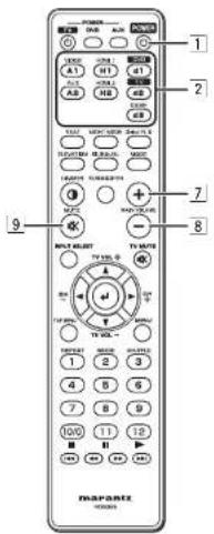
1 POWER button
Press this button to turn on the unit or to set it to standby mode.
2 | Input select buttons
These buttons are used to select the input source to be played. Press the input source button you want to play.
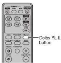
3 Dolby PL II button
Press this button to switch the Dolby Pro Logic II sound field environment. Each press switches among Pro Logic II MOVIE, Pro Logic II MUSIC and OFF.
Note:
This button functions when the analog input signal or 2-ch PCM input signal is selected.
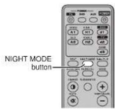
4 NIGHT MODE button
Press this button when you want to lower the volume of the source for cases such as movie viewing at night.
As the enhanced parts of the reproduced sound are suppressed in this mode, you can enjoy the sound without elevating the entire volume.
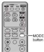
5 MODE button
Press this button to listen to the binaural recording source.
6 | BILINGUAL button
Press this button to switch the bilingual sound output from the TV when the unit receives a high-definition TV broadcast (AAC audio signal).
7 MAIN VOLUME + button
Press this button to increase the volume of the unit.
8 MAIN VOLUME – button
Press this button to decrease the volume of the unit.
9 MUTE button
Press this button to mute the sound temporarily. Press it again to restore the sound.
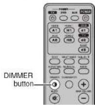
10 DIMMER button
Press this button to dim the display window.
11 SUBWOOFER button
This button is used to activate a commercially available or the Marantz SW7001 subwoofer with a built-in amplifier connected to the unit.
Note:
This function is activated at the factory. When no subwoofer is connected to the unit, press this button to turn off the indicator.
12 ELEVATION button
Press this button to switch the height of the unit installation position. "L" (lower than the TV position) or "H" (higher than the TV position) can be selected.
13 SEAT button
[For number of audience]
Press this button once to switch the number of the audience between "1P" (one person) and "2P" (two or more persons).
[For the viewing/listening distance]
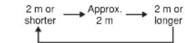
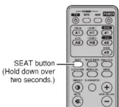
Hold down this button for over 2 seconds to switch the distance between the audience and the unit from among "2 m or shorter," "Approx. 2 m" and "2 m or longer."
Notes:
- When the audience is 2.5 m or farther away from the unit and the viewing/listening distance is set to "2 m or longer," the stereophonic effect of the unit may be reduced.
- When the audience is close 1.5 m or less to the unit and the viewing distance is set to "2 m or shorter," the stereophonic effect of the unit may be reduced.
NAMES AND FUNCTIONS OF PARTS
■ Buttons used for a TV
Notes:
- Before using the remote controller for a TV, set the preset code for the TV.
- For details on the operation of the TV, refer to the instruction manual supplied with the TV.
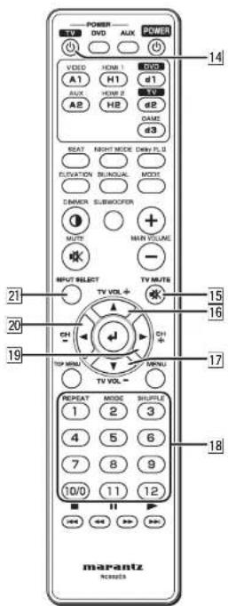
14 TV POWER button
Press this button to turn on the TV or to set it to standby mode.
15 TV MUTE button
Press this button to mute the TV sound temporarily. Press it again to restore the sound.
16 TV VOL + button
Press this button to increase the volume of the TV.
17 TV VOL - button
Press this button to decrease the volume of the TV.
18 Numeric (1-12) buttons
These buttons are used for direct TV channel selection.
19 CH (channel) + button
Press this button to scan forward through the TV channels.
20 CH (channel) - button
Press this button to scan reverse through the TV channels.
21| INPUT SELECT button
Press this button to switch between the TV broadcast and a video input.
■ Preset code setting
The remote control codes of TVs of manufacturers other than Marantz are preset in the supplied remote controller. To use the supplied remote controller for the TV of another manufacturer, enter the code in the remote controller.
-
Check the four-digit code number of your TV manufacturer in the preset code number lists shown below.
-
While holding down the TV POWER button 14 on the remote controller, press the Numeric buttons 18 to enter the four-digit manufacturer's code number.
Presetting the code number to the remote controller is complete.
Notes:
- Some of the preset codes in the lists may not be compatible with your TV.
- If your TV does not operate with the remote controller after entering the preset code, try to enter another code number of the manufacturer.
- Some of the functions of the TV may not be operable with the remote controller even after entering the code.
NAMES AND FUNCTIONS OF PARTS
■ TV preset code number lists
| Acer | 1141 |
| Admiral | 1002, 1009, 1089 |
| Aiko | 1059 |
| Aiwa | 1117, 1118 |
| Akai | 1001 |
| Amtron | 1023 |
| Anam | 1113 |
| Anam National | 1023, 1069, 1092 |
| AOC | 1003, 1024, 1049, 1127 |
| Audiovox | 1023 |
| Bell & Howell | 1009, 1025 |
| Benq | 1104, 1142 |
| Broksonic | 1003, 1097, 1098, 1113 |
| Celebrity | 1001 |
| Citizen | 1003, 1013, 1023 |
| 1026, 1059, 1063 | |
| Colortyme | 1003, 1043 |
| Contec | 1113 |
| Contec/Cory | 1023, 1045, 1047 |
| Craig | 1020, 1022, 1023, 1113 |
| Crown | 1023, 1067 |
| Curtis Mathes | 1003, 1013, 1025 |
| 1026, 1062, 1103, 1110 | |
| Daewoo | 1003, 1013, 1024, 1035 |
| 1036, 1059, 1084, 1101 | |
| Daytron | 1003, 1013, 1016 |
| Dimensia | 1103, 1110 |
| Dumont | 1003, 1010, 1153 |
| Electroband | 1001 |
| Electrohome | 1001, 1003, 1069, 1133 |
| Emerson | 1003, 1013, 1015, |
| 1020, 1021, 1022, 1023 | |
| 1025, 1038, 1044, 1045 | |
| 1048, 1055, 1061, 1094 | |
| 1096, 1099, 1101, 1113 | |
| Envision | 1003 |
| Fisher | 1025, 1051, 1091, 1160 |
| Fujitsu | 1038, 1124, 1125, 1155 |
| Funai | 1023, 1038, 1113 |
| Gateway | 1150 |
| GE | 1003, 1018, 1022, 1046 |
| 1054, 1069, 1085, 1103 | |
| 1110, 1113, 1133, 1136, 1153 | |
| Goldstar | 1003, 1013, 1024 |
| 1030, 1045, 1080 | |
| 1100, 1112, 1154 | |
| Hallmark | 1003 |
| Hlsense | 1116 |
| Hitachi | 1003, 1012, 1031, 1032 |
| 1037, 1041, 1045, 1047 | |
| 1065, 1068, 1082, 1088 | |
| 1094, 1139, 1140, 1145, 1159 | |
| Infi nity | 1067 |
| Janeil | 1134 |
| JBL | 1067 |
| JC Penney | 1003, 1013, 1018 |
| 1019, 1024, 1026 | |
| 1046, 1047, 1054 | |
| 1063, 1083, 1085 | |
| 1100, 1103, 1110 | |
| 1112, 1133, 1154 | |
| Jensen | 1003 |
| JVC | 1028, 1029, 1045 |
| 1047, 1050, 1060, 1065 | |
| Kawasho | 1001, 1003 |
| Kenwood | 1003 |
| Kloss Novabeam | 1023, 1056, 1057, 1134 |
| KTV | 1013, 1023, 1033 |
| 1034, 1073, 1099, 1113 | |
| LG | 1024, 1030 |
| M.Wards | 1002, 1009, 1038 |
| Magnavox | 1003, 1052, 1053 |
| 1056, 1057, 1063 | |
| 1067, 1081, 1106 | |
| Marantz | 1003, 1031, 1067, 1122 |
| Mitsubishi | 1003, 1024, 1051 |
| 1115, 1122, 1133 | |
| Motorola | 1014, 1069 |
| NEC | 1003, 1012, 1024, 1043, 1069 |
| NET-TV | 1137, 1150 |
| Orion | 1020, 1096 |
| Panasonic | 1017, 1067, 1069, 1095, 1111 |
| Philips | 1003, 1011, 1045, 1052 |
| 1054, 1056, 1057, 1058 | |
| 1063, 1067, 1069, 1106 | |
| Pioneer | 1003, 1018, 1037 |
| 1070, 1071, 1094 | |
| 1145, 1147, 1149 | |
| Plasmsync | 1135 |
| Portland | 1003, 1013, 1024, 1059 |
| Price Club | 1026 |
| Prism | 1018 |
| Proscan | 1004, 1005, 1006, 1007 |
| 1008, 1085, 1103, 1110 | |
| Proton | 1003, 1045 |
| Quasar | 1010, 1069, 1073, 1111, 1153 |
| Radio Shack | 1003, 1013, 1015, 1023, 1024, 1025, 1045 |
| 1100, 1103, 1110, 1113 | |
| RCA | 1003, 1004, 1005 |
| 1006, 1007, 1008 | |
| 1014, 1024, 1049, 1069 | |
| 1075, 1079, 1085, 1087 | |
| 1088, 1093, 1094, 1101 | |
| 1103, 1110, 1113,1153 | |
| Realistic | 1013, 1015, 1023, 1025 |
| 1045, 1100, 1103, 1110 | |
| Runco | 1010, 1153 |
| Sampo | 1150 |
| Samsung | 1003, 1013, 1024, 1026 |
| 1040, 1045, 1062, 1078 | |
| 1083, 1090, 1100, 1105, 1114 | |
| 1120, 1121, 1146, 1148, 1157 | |
| Sansui | 1119 |
| Sanyo | 1003, 1025, 1051, 1072 |
| 1077, 1091, 1156, 1157, 1158 | |
| Sharp | 1003, 1013, 1014 |
| 1015, 1045, 1055, 1064 | |
| 1066, 1076, 1089, 1123 | |
| Signature | 1009 |
| Sony | 1001, 1102, 1108 |
| Soundesign | 1003, 1023, 1038, 1063, 1113 |
| Starlite | 1023 |
| Supre-Macy | 1134 |
| Sylvania | 1003, 1039, 1042 |
| 1052, 1053, 1056, 1057 | |
| 1063, 1067, 1089, 1151 | |
| Symphonic | 1023, 1039, 1044 |
| Tandy | 1014 |
| Tatung | 1069 |
| Technics | 1018 |
| Techwood | 1003, 1019 |
| Teknika | 1003, 1009, 1013, 1023 |
| 1024, 1026, 1038, 1045 | |
| 1047, 1059, 1063, 1111, 1113 |
| Telecaption | 1074 |
| Toshiba | 1003, 1019, 1025 |
| 1026, 1042, 1074, 1098 | |
| 1107, 1111, 1135, 1136 | |
| Totevision | 1013 |
| Universal | 1046, 1054 |
| Video Concepts | 1113 |
| Viewsonic | 1006, 1022, 1109 |
| 1128, 1129, 1130, 1131 | |
| 1138, 1143, 1145, 1150 | |
| Wards | 1003, 1009, 1015 |
| 1024, 1038, 1044, 1046 | |
| 1052, 1054, 1056, 1057 | |
| 1067, 1086, 1103, 1110 | |
| White Westinghouse | 1101, 1001 |
| Yamaha | 1003, 1024 |
| Zenith | 1003, 1009, 1010 |
| 1132, 1144, 1153 |
NAMES AND FUNCTIONS OF PARTS
■ Before using the remote controller for Marantz products
-
Press the button specified for the equipment you want to operate.
-
DVD player: "d1" button on the remote controller
-
IS201: "A2" button on the remote controller
-
Operate the unit using the buttons described in the respective list.
Notes:
- For details on operation, please refer to the instruction manual supplied with the connected Marantz products.
- Some models may not operate with the remote controller supplied with this unit.
■ Buttons used for a Marantz DVD player
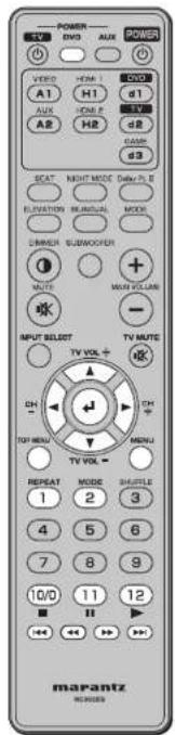
| DVD POWER button | Turns on the DVD or sets it to standby mode. |
| ▲ button | Moves the cursor up. |
| ▼ button | Moves the cursor down. |
| ◀ button | Moves the cursor left. |
| ▶ button | Moves the cursor right. |
| ◀ button | Executes the selected item. |
| TOP MENU button | Displays the top menu of a DVD disc. |
| MENU button | Displays the setting menu of a DVD player. |
| REPEAT button | Repeats playback of a chapter or disc. |
| MODE button | Selects the Super Audio CD sound mode. |
| ■ button | Stops playback. |
| ■ button | Pauses playback. |
| ▶ button | Starts playback. |
| ◀◀ button | Returns to the beginning of the current music or chapter. |
| ◀◀ button | Fast backward search |
| ▶▶ button | Fast forward search |
| ▶▶ button | Skips to the next music or chapter. |
NAMES AND FUNCTIONS OF PARTS
■ Buttons used for the Marantz IS201 iPod universal dock
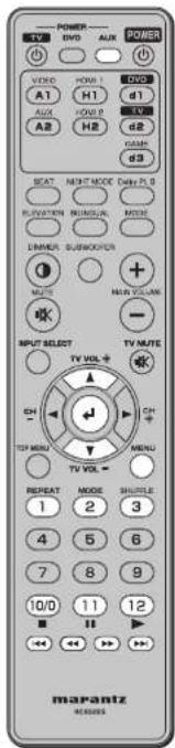
| AUX POWER button | Turns on the power of an iPod connected to the IS201 or sets it to standby mode. |
| ▲ button | Functions the same as turning the click wheel of an iPod counterclockwise.Note: The iPod volume cannot be adjusted. |
| ▼ button | Functions the same as turning the click wheel of an iPod clockwise.Note: The iPod volume cannot be adjusted. |
| ← button | Functions the same as the click wheel select button of an iPod. |
| MENU button | Functions the same as the click wheel menu button of an iPod. |
| REPEAT button | Switches the iPod repeat mode. (Track repeat → All repeat → Off) |
| MODE button | Switches the mode of the IS201 (OSD/LCD) |
| SHUFFLE button | Switches the iPod shuffle mode. (Track → Album → Off) |
| ■ button | Stops iPod playback. |
| ■ button | Pauses iPod playback. |
| ► button | Starts iPod playback. |
| ◄◄ button | Returns to the beginning of the current content by one press. Returns to the previous content by two successive presses. |
| ◄◄ button | Fast backward search |
| ►► button | Fast forward search |
| ►► button | Skips to the next content by one press. |
CONNECTIONS
Notes:
- Do not connect the AC power cords of the unit and connected equipment to the wall outlet before making all connections.
- Insert the connecting cable plugs firmly into the connectors. A loose connection may result in noise.
- Be sure to connect the L (left) channel to the white connector, and the R (right) channel to the red connector.
- Connect the input and output connectors correctly.
- Please refer to the respective instruction manual for connected equipment.
CONNECTING DIGITAL EQUIPMENT WITH THE OPTICAL CONNECTOR
• This unit is equipped with three optical digital inputs.
- Use the commercially available optical connecting cable for connection.
■ Connections
- Connect a DVD player to the OPT IN 1 connector on the unit.
The Marantz DVD player is assigned to the d1 button on the supplied remote controller, and the basic operations of the Marantz DVD player are enabled with the remote controller.
- Connect a TV to the OPT IN 2 connector on the unit.
A TV is assigned to the d2 button on the supplied remote controller, and the basic operations of the TV are enabled with the remote controller.
- Connect a video game console to the OPT IN 3 connector on the unit.
A video game console is assigned to the d3 button on the supplied remote controller.
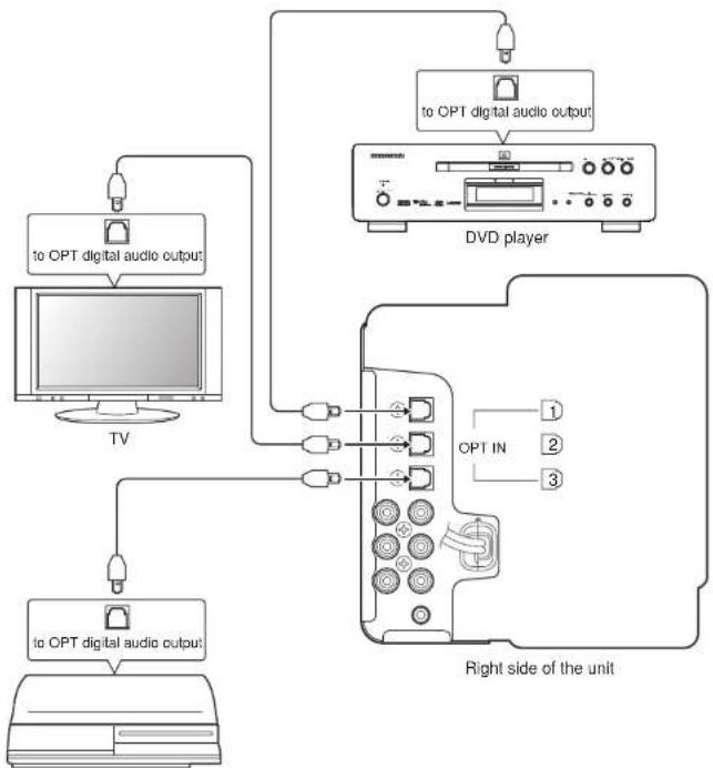
flowchart
graph TD
    A["TV"] --> B["to OPT digital audio output"]
    A --> C["to OPT digital audio output"]
    D["DVD player"] --> E["to OPT digital audio output"]
    D --> F["Right side of the unit"]
    G["Central Unit"] --> H["1"]
    G --> I["2"]
    G --> J["3"]
Video game console
CONNECTIONS
CONNECTING ANALOG EQUIPMENT
• This unit is equipped with two analog inputs.
- Use a commercially available RCA audio cable for connection.
■ Connections
- Connect a VCR to the ANALOG IN 1 connector on the unit.
A VCR is assigned to the A1 (VIDEO) button on the supplied remote controller. - Connect the IS201 iPod universal dock to the ANALOG IN 2 connector on the unit.
The IS201 is assigned to the A2 (AUX) button on the supplied remote controller, and the basic operations of the IS201 are enabled with the remote controller.
CONNECTING DIGITAL EQUIPMENT EQUIPPED WITH THE HDMI CONNECTOR
- This unit is equipped with two HDMI digital inputs and one HDMI digital output.
- Use a commercially available HDMI connecting cable for connection.
Note:
The audio input to the HDMI jacks can be played back by this unit. In such case, audio signals are not output to the TV or projector.
■ Connections
- Connect a hard disc recorder, etc. equipped with an HDMI connector to the HDMI IN 1 connector on the unit.
The connected equipment is assigned to the H1 button on the supplied remote controller. - Connect a video game console equipped with an HDMI connector to the HDMI IN 2 connector on the unit.
flowchart
graph TD
    A["Left side of the unit"] --> B["HDMI Ver1.1"]
    B --> C["HDMI OUT"]
    B --> D["HDMI IN 1"]
    B --> E["HDMI IN 2"]
    C --> F["to HDMI input"]
    D --> G["to HDMI output"]
    E --> H["to HDMI output"]
    F --> I["TV or video projector"]
    G --> J["Hard disc recorder, TV tuner, etc."]
    H --> K["Video game console"]
CONNECTIONS
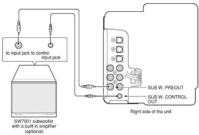
CONNECTING A SUBWOOFER
- For connection with the optional SW7001 subwoofer, use the connecting cable supplied with the SW7001.
- If the power of the SW7001 is turned on after connection, it will be turned on or goes into standby mode in conjunction with the operations of the unit. This function is not available with other manufacturers' subwoofers.
■ Connections
- Connect the SUB W. PREOUT jack on the unit to the input jack on the SW7001.
- Connect the SUB W. CONTROL OUT jack on the unit to the control input jack on the SW7001.
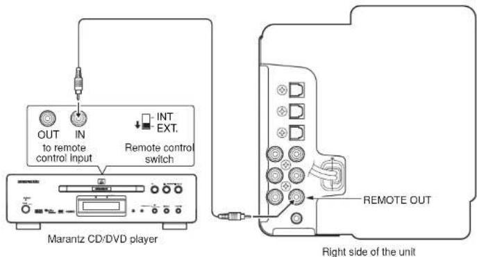
REMOTE CONTROL CONNECTIONS
- The REMOTE OUT jack is used for connection with the Marantz DVD player, etc. equipped with remote control output.
- When the Marantz DVD player or the IS201 is located in a place where the infrared beam cannot be easily received, make a remote control connection. When you operate the remote controller pointing toward this unit, a received command signal is transmitted to the connected equipment.
■ Connections
- Connect the Marantz DVD player to the REMOTE OUT jack on the unit using the remote control cable supplied with the player.
Note:
For this connection, set the remote control switch on the rear panel of the connected equipment to EXT.
INSTALLATION
■ Installing the unit
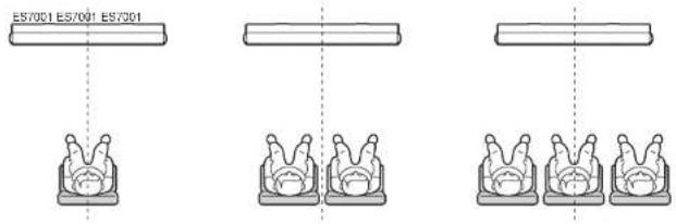
• Install the unit so that the center of the seat is aligned with the center of the unit.
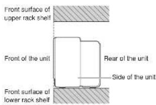
- When mounting the unit in a rack, align the front surface of the rack with the front of the unit.
Notes:
- The unit weighs 12 kg. Use commercially available wires, etc. to take measures to prevent the unit from falling due to vibration caused by earthquake or mishandling by children.
- Do not place the unit on the surface of an object generating heat such as a CRT-based TV.
• If the TV picture is blurred, install the unit apart from the TV.
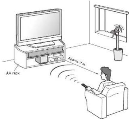
[To mount the unit in the optional AV rack]
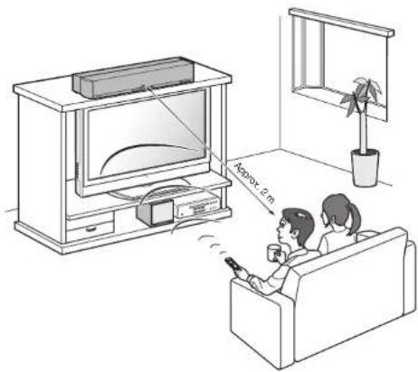
[To install the unit in a higher place than the connected TV]
natural_image
Illustration of a family watching TV in a living room, with a wall-mounted monitor and a window (no text or symbols)BASIC OPERATIONS
TURNING ON THE UNIT
- Turn on the power of the audio equipment connected to this unit. Set the input selector on the audio equipment to this unit.
- Connect the AC power cord to the wall outlet.
- Press the ON/STANDBY button ① on the unit or POWER button ① on the remote controller to turn on the power of the unit.
• Each time the button is pressed, the power of the unit is switched between on and standby mode.
■ Auto-power-off function
- If the power of the connected DVD player, TV, video game console, etc. is turned off and the power of the unit remains on, the unit automatically goes into standby mode.
- If no signal is input to this unit for five minutes with the input selector set to "DVD," "TV" or "GAME," the unit automatically goes into standby mode.
PLAYING THE INPUT SOURCE
The procedure for operating the unit for playback with a DVD player is described below as a representative example.
Check that the DVD player and the unit are correctly connected, referring to "Connections" in this Guide.
■ To play a DVD disc with the DVD player
- Turn on the power of the DVD player.
- Press the ON/STANDBY button ① on the unit or POWER button ① on the remote controller to turn on the unit.
- Press the INPUT SELECT button ⑫ on the unit repeatedly to select "d1" or the d1 button of the input select buttons ② on the remote controller.
- Load a disc into the DVD player and start playback.
- Adjust the volume with the VOLUME +/- buttons ③/④ on the unit or the MAIN VOLUME +/- buttons ⑦/⑧ on the remote controller.
■ Muting function
Press the MUTE button 9 on the remote controller to mute the sound temporarily. While the muting function is activated, the volume level indication flashes in the display window.
To restore the sound, press the MUTE button 9 or the MAIN VOLUME +/- buttons 7/8 on the remote controller, or the VOLUME +/- buttons 3/4 on the unit.
SETTINGS
The following setting items are available with this unit.
- Setting Installation Height of Speakers (page 17)
- Setting the number of audience (page 17)
- Setting the viewing/listening distance (page 18)
- Setting the subwoofer output (page 18)
- Setting the binaural mode (page 19)
- Setting the Dolby Pro LogicII (page 19)
- Mode setting multi-channel TV sound mode (page 20)
- Setting the night mode (page 20)
- Setting the dimmer (page 20)
- Resetting Items to factory preset settings (page 21)
SETTING INSTALLATION HEIGHT OF SPEAKERS
- This item is used to set the installation location (height) of the unit.
- Press the ELEVATION button on the remote controller to change the setting.
• Each time the button is pressed, the setting switches as described below. - This item is set at the factory as if the unit is installed in a lower place than the connected TV (mounted on the upper shelf of the optional RM7001 AV).
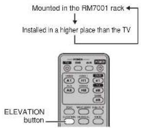
● When the unit is mounted in the RM7001 rack

● When the unit is installed in a higher place than the connected TV

SETTING THE NUMBER OF AUDIENCE
- This item is used to set whether you view/ listen to the source input to this unit alone or with multiple persons in a room.
- Press the SEAT button on the remote controller to switch to "2 or more persons."
- This item is set to "2 or more persons" at the factory.
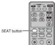
● When audience is one person
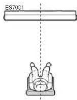
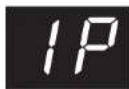
- When audience is two or more persons
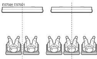
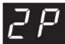
Note:
When there is a large audience, try both settings and select the setting which gives a better stereophonic effect.
SETTINGS
SETTING THE VIEWING/ LISTENING DISTANCE
- This item is used to set the distance between the unit and audience.
- Hold down the SEAT button on the remote controller for over two seconds to change the setting.
Each time you hold down the button for over two seconds while the viewing/listening distance indication is displayed in the display window, the setting switches as described below.
This item is set to "Approx. 2 m" at the factory.
● When the distance is shorter than 2 m

● When the distance is approximately 2 m
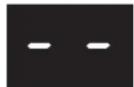
● When the distance is longer than 2 m

Notes:
- When the audience is 2.5 m or farther away from the unit with the viewing/listening distance set to "2 m or longer," the stereophonic effect of the speakers may be reduced.
- When the audience is close 1.5 m or less to the unit with the viewing/listening distance set to "2 m or shorter," the stereophonic effect of the speakers may be reduced.
SETTING THE SUBWOOFER OUTPUT
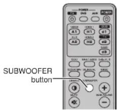
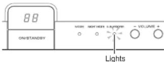
- Press the SUBWOOFER button on theremote controller when you use a commercially available or optional SW7001 subwoofer with a built-in amplifier so that the SUB WOOFER indicator lights. The subwoofer output is activated, enabling output of low-frequency sound from the connected subwoofer. The low-frequency sound from this unit is adjusted so that it does not overlap with that from the connected subwoofer.
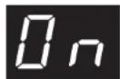
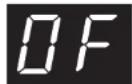
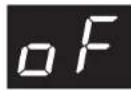
- To turn off the subwoofer output, press the SUBWOOFER button on the remote controller once to display the "On" indication in the display window, then press it again while the indication is displayed.
The indication in the display window changes to "OF" and the SUB WOOFER indicator goes out. The subwoofer output is set to off and low-frequency sound of the unit is restored.
- This setting is set to "On" at the factory.
- When the subwoofer output is set to on
● When the subwoofer output is set to off
Notes
- Be sure to set the subwoofer output to off when you do not use an external subwoofer. Optimum low-frequency sound is only output from the speakers built in the unit with the subwoofer output set to off.
- You cannot adjust the volume level of the connected subwoofer with this unit. Adjust it with the connected subwoofer.
SETTINGS
SETTING THE BINAURAL MODE
- Press the MODE button on the remote controller to listen to the audio source recorded in binaural mode.
• The MODE indicator lights in blue and the stereophonic effect of the sound source is reproduced especially realistically.
Note:
The binaural mode is automatically canceled when a sound source other than 2-channel PCM sound or analog sound is input.
SETTING THE DOLBY PRO LOGIC IIMODE
- This item is used to select the sound field environment produced by Dolby Pro Logic II.
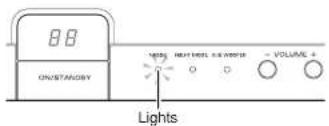
- When the unit is set to "PL II MOVIE" or "PL II MUSIC," the Dolby PL II indicator lights.
• Each time you press the Dolby PL II button on the remote controller, the sound field setting changes as follows:

● When "PL II MOVIE" is selected
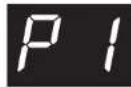
Stereophonic effect is obtained from the soundtrack of a stereo movie encoded by Dolby Surround.
● When "PL II MUSIC" is selected
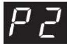
Stereophonic effect is obtained from a conventional stereo source such as a CD player, iPod, etc.
- When "OFF" is selected
The Dolby Pro Logic II mode is turned off. If the signal source is input from the ANALOG IN 1 (VCR) or 2 (AUX) jacks, or 2-channel digital signal is input when the Dolby Pro Logic II mode is set to "PL II MOVIE" or "PL II MUSIC," the setting is automatically switched to "PL II MOVIE" and the Dolby PL II indicator lights.
SETTINGS
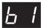
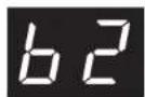
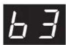
SETTING MULTI-CHANNEL TV SOUND MODE
- When the unit receives a high-definition broadcast (AAC signal), the AAC indicator lights in yellow.
In this case, you can select the output sound from the TV by pressing the BILINGUAL button on the remote controller.
• Each press of the button changes the sound as follows:
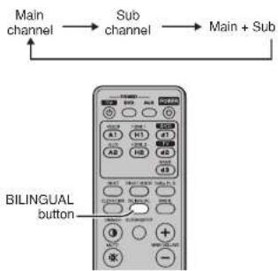
flowchart
graph LR
    A["Main channel"] --> B["Sub channel"]
    B --> C["Main + Sub"]
    D["BILINGUAL button"] --> E["Control panel with buttons, display, and function blocks"]
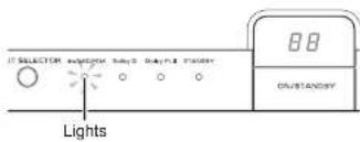
- When "Main channel" is selected
- When "Sub channel" is selected
- When "Main+Sub" is selected
Note:
Some broadcasts may not feature multi-channel audio (AAC signal).
SETTING THE NIGHT MODE
This mode is convenient for enjoying a movie, etc. at night. You can enjoy the playback sound without elevating the entire volume as only the enhanced parts of the sound are suppressed in this mode. Press the NIGHT MODE button on the remote controller to activate this mode. The NIGHT MODE indicator lights in green on the unit. The night mode is only available when the Dolby Digital indicator is lit in blue.
Note:
Since the night mode effect is set by the Dolby digital software, the desired effect may not be achieved with software that does not support the Dolby digital signal. This mode cannot be used when a dts, AAC or PCM signal is input.
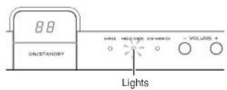
SETTING THE DIMMER
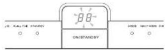
Press the DIMMER button on the remote controller to dim the display window of the unit. To cancel the dimmer mode, press the button again.
SETTINGS
TROUBLESHOOTING
RESETTING ITEMS TO FACTORY PRESET SETTINGS
To reset all the items that have been set to the factory preset settings (initial settings), hold down the ON/STANDBY button and VOLUME + button on the unit simultaneously for over 3 seconds while the power of the unit is on. After two seconds, the unit goes into standby mode, turns on again, then the settings are reset to their factory preset ones.
■ Initial settings of unit
Power ...... ON Input selector ...... DVD Display window ...... volume level indication Volume level ...... 00
■ Initial settings of setting items
Speaker installation height .... L (installed in a lower place than the connected TV) Number of audience ....2P (2 or more persons) Viewing/listening distance .... -- (2 m) Subwoofer .. On (subwoofer output activated) Binaural mode .... off Dolby PL II .... P1 (PL II MOVIE) Multi-channel broadcast ....b1 (main channel) Night mode .... off Dimmer .... normal brightness Muting .... off
■ Before considering it as a failure
In case of trouble with this component, first check the following before calling for service.
What seems to be a serious malfunction is often due to a simple operation mistake.
If the trouble is not fixed after making the following checks, contact the place of purchase, your nearest Marantz dealer, our customer service center, or our repair service center.
Power does not turn on.
- Is the power cord inserted into the wall outlet securely?
→ Plug in the power cord securely.
- Is the STANDBY indicator lit?
→ Press the POWER button on the remote controller.
No sound is heard from the speakers.
- Is input source selection with the INPUT SELECTOR buttons on the front panel correct?
→ Check that the input source is selected correctly.
- Are you operating the playback equipment correctly?
→ Refer to the instruction manual supplied with the playback equipment.
- Are the connecting cables between the unit and the playback equipment correctly connected?
→ Connect the connecting cables correctly.
- Is the muting function deactivated?
→ Set the muting function to off.
Noises appear while the CD or LD that contains dts signal is played.
- Is the playback equipment not connected to the ANALOG IN jacks on the unit?
→ Check that the playback equipment is equipped with digital output, and connect it to the digital input on this unit.
- Does the CD or LD support the dts signal output?
→ Refer to the instruction manual supplied with the playback equipment.
96 kHz PCM signal cannot be played.
- This unit is compatible with 32 kHz, 44.1 kHz and 48 kHz sampling frequencies.
→ Downsample the DVD player audio to 48 kHz.
■ About the Protective Circuit
This unit incorporates a protective circuit that protects the amplifier circuits and speaker system against damage.
As soon as the protective circuit works, the unit goes into standby mode and the STANDBY indicator flashes at the same time.
● For power-on
For 3 or 4 seconds after the power of the unit is turned on the protective circuit works and the sound is muted. Once the amplifier circuits are stabilized, the protective circuit is released and the sound is restored.
● For heat-up of the power amplifier
When the power amplifier of the unit heats up under the following conditions, the protective circuit works and the unit goes into the standby mode.
- The unit is kept used with excessive signal input, and the temperature of the main amplifier section exceeds the set operating temperature.
- Since the ventilation holes at the rear of the unit are blocked or the unit is installed in a narrow rack, the internal temperature of the unit exceeds the set operating temperature.
In this case, wait until the temperature is sufficiently lowered, then turn on the unit and operate it at a lower volume.
SPECIFICATIONS
● Audio power amplifier
Rated power output (20 Hz-20 kHz / THD = 0.05%)
.26
Maximum power output (1 kHz/JEITA)
30
Frequency characteristics
Analog input: ANALOG IN 1
20 Hz-20 kHz (± 3 dB)
Digital input: PCM 44.1 kHz
.20 Hz-20 kHz (± 3 dB)
S/N ratio: PCM 44.1 kHz
**********
● Decoding
Compatible playback signal formats
PCM audio (fs = 32 kHz, 44.1 kHz, 48 kHz)
DOLBY DIGITAL
dts
AAC
Binaural
● Power supply
Power requirements ..... AC 230 V, 50/60 Hz
Power consumption 40 W
..... 125 W (6Ω, 30 W x
Power consumption in standby mode ... 0.8 W
Input
OPT IN (optical digital) ....3 inputs
HDMI IN (Version 1.1) ......2 inputs
ANALOG IN 2 inputs (stereo)
●6Ω Output
HDMI OUT (Version 1.1) ...... 1 output
SUB W. PREOUT .... 1 output
REMOTE OUT 1 output
Speakers
Tweeter 1.9 cm dome x 2
100 Midrange 8 cm cone x 2
Woofer 12 cm cone x 2
● Dimensions (unit)
Width 1,080 mm
Height 153 mm
Depth 144 mm
Mass (unit) 12 kg
● Supplied accessories
Remote controller .... 1
AAA batteries 2
User Guide (this manual).... 1
outputs)
Note:
The speaker nets cannot be removed.

natural_image
Pure geometric diagram of a cylinder with no text, numbers, or symbols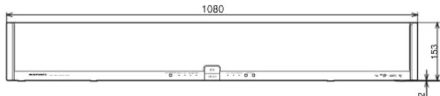
Specifications subject to change without prior notice.
OTHERS
The section describes the care and maintenance tasks that must be performed to optimize the operation of your Marantz component.
■ Cleaning of equipment external surfaces
The exterior finish of your unit will last indefinitely with proper care and cleaning. Never use scouring pads, steel wool, scourging powders or harsh chemical agents (e.g., lye solution), alcohol, thinner, benzine, insecticide or other volatile substances as these wil mar the finish of the equipment. Likewise, never use cloths containing chemical substances. If the equipment get dirty, wipe the external surfaces with a soft, lint-free cloth. If the equipment becomes heavily soiled:
- dilute some washing up liquid in water, in a ratio of one part detergent to six parts water.
- dip a soft, lint free in the solution and wring the it is damp.
- wipe the equipment with the damp cloth.
- dry the equipment by wiping it with a dry cloth.

■ Repairs
Only the most competent and qualified service technicians should be allowed to service the factory-trained warranty station personnel have the knowledge and special facilities needed for repair and calibration of this precision equipment. After the warranty period has expired, repairs will be performed for a charge if the equipment can be returned to normal operation.
In the event of difficulty, refer to your dealer or write directly to the nearest location to you that is listed on the Marantz Authorized Service Station list. If writing, please include the model and serial number of the equipment together with a full description of what you think is abnormal about the equipment's behaviour.
www.marantz.com
You can find your nearest authorized distributor or dealer on our website.
marantz®
is a registered trademark.
- RETAIN YOUR PURCHASE RECEIPT
- IMPORTANT
- FOR U.K. ONLY
- FRANÇAIS
- GARANTIE
- AVERTISSEMENTS
- ■ Accessories Check
- A NOTE ABOUT RECYCLING
- CONTENTS
- FEATURES
- [MAIN FUNCTION]
- [DIGITAL AMPLIFIER SECTION]
- [PWM PROCESSOR SECTION]
- [POWER SUPPLY SECTION]
- [CABINET]
- [OTHER FEATURES]
- ● DOLBY
- AAC
- ● dts
- ● OPSODIS
- HDMI
- BEFORE USING
- ■ Equipment mains working setting
- Copyright
- ■ Do Not Locate in the Following Places
- ■ Keep Objects Off
- ■ Do not touch hot spots during and immediately after use
- ■ Cautions on handling power cord
- ■ For use of Remote controller
- - Loading batteries
- ● Cautions on handling batteries
- ● Operatable range of Remote controller
- Cautions:
- NAMES AND FUNCTIONS OF PARTS
- ① ON/STANDBY button
- ② Display window
- ③ VOLUME + button
- ④ VOLUME - button
- ⑤ SUB WOOFER Indicator
- Note:
- ⑥ NIGHT MODE indicator
- ⑦ MODE indicator
- ⑧ STANDBY indicator
- ⑨ Dolby PL II indicator
- ⑩ Dolby D indicator
- ⑪ dts/AAC/PCM indicator
- ⑫ INPUT SELECTOR button
- ① OPT IN 1 (DVD)/2 (TV)/3 (GAME)
- connectors
- ② ANALOG IN 1 (VCR)/2 (AUX) Jacks
- ③ SUB W. PREOUT jack
- ④ SUB W. CONTROL OUT jack
- ⑤ REMOTE OUT Jack
- ⑥ AC power cord
- ⑦ HDMI IN 1/2 connectors
- ⑧ HDMI OUT connector
- REMOTE CONTROLLER: RC002ES
- POWER button
- | Input select buttons
- Dolby PL II button
- NIGHT MODE button
- MODE button
- | BILINGUAL button
- MAIN VOLUME + button
- MAIN VOLUME – button
- MUTE button
- DIMMER button
- SUBWOOFER button
- ELEVATION button
- SEAT button
- [For number of audience]
- [For the viewing/listening distance]
- Notes:
- ■ Buttons used for a TV
- TV POWER button
- TV MUTE button
- TV VOL + button
- TV VOL - button
- Numeric (1-12) buttons
- CH (channel) + button
- CH (channel) - button
- 21| INPUT SELECT button
- ■ Preset code setting
- ■ Before using the remote controller for Marantz products
- ■ Buttons used for a Marantz DVD player
- ■ Buttons used for the Marantz IS201 iPod universal dock
- CONNECTIONS
- CONNECTING DIGITAL EQUIPMENT WITH THE OPTICAL CONNECTOR
- ■ Connections
- CONNECTING ANALOG EQUIPMENT
- CONNECTING DIGITAL EQUIPMENT EQUIPPED WITH THE HDMI CONNECTOR
- CONNECTING A SUBWOOFER
- REMOTE CONTROL CONNECTIONS
- INSTALLATION
- ■ Installing the unit
- BASIC OPERATIONS
- TURNING ON THE UNIT
- ■ Auto-power-off function
- PLAYING THE INPUT SOURCE
- ■ To play a DVD disc with the DVD player
- ■ Muting function
- SETTINGS
- SETTING INSTALLATION HEIGHT OF SPEAKERS
- SETTING THE NUMBER OF AUDIENCE
- SETTING THE VIEWING/ LISTENING DISTANCE
- SETTING THE SUBWOOFER OUTPUT
- Notes
- SETTING THE BINAURAL MODE
- SETTING THE DOLBY PRO LOGIC IIMODE
- ● When "PL II MOVIE" is selected
- ● When "PL II MUSIC" is selected
- - When "OFF" is selected
- SETTING MULTI-CHANNEL TV SOUND MODE
- SETTING THE NIGHT MODE
- SETTING THE DIMMER
- TROUBLESHOOTING
- RESETTING ITEMS TO FACTORY PRESET SETTINGS
- ■ Initial settings of unit
- ■ Initial settings of setting items
- ■ Before considering it as a failure
- Power does not turn on.
- No sound is heard from the speakers.
- Noises appear while the CD or LD that contains dts signal is played.
- kHz PCM signal cannot be played.
- ■ About the Protective Circuit
- ● For power-on
- ● For heat-up of the power amplifier
- SPECIFICATIONS
- ● Audio power amplifier
- ● Decoding
- ● Power supply
- Input
- ●6Ω Output
- Speakers
- ● Dimensions (unit)
- ● Supplied accessories
- OTHERS
- ■ Cleaning of equipment external surfaces
- ■ Repairs
Brand : MARANTZ
Model : ES7001
Category : Loudspeaker