
NM-C110 - Security Camera MITSUBISHI - Free user manual and instructions
Find the device manual for free NM-C110 MITSUBISHI in PDF.


User questions about NM-C110 MITSUBISHI
0 question about this device. Answer the ones you know or ask your own.
Ask a new question about this device
Download the instructions for your Security Camera in PDF format for free! Find your manual NM-C110 - MITSUBISHI and take your electronic device back in hand. On this page are published all the documents necessary for the use of your device. NM-C110 by MITSUBISHI.
USER MANUAL NM-C110 MITSUBISHI
This unit complies with the requirements of the EC Directive 2004/108/EC, "EMC Directive". The requirements for the susceptibility according to EN 55024 and the requirements for interference according to EN 55022 are observed for the operation on residential areas, business, light industrial premises and in small scale enterprises, inside as well as outside of the building. All places of operation are characterized by their connection to the public low voltage power supply system.
Warning
This is class A product. In a domestic environment this product may cause radio Interference in which case the user may be required to take adequate measures.
natural_image
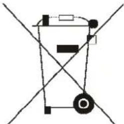
Pure electrical circuit lines without any symbolsNote: This symbol mark is for EU countries only. This symbol mark is according to the directive 2002/96/EC Article 10 Information for users and Annex IV, and/or to the directive 2006/66/EC Article 20 Information for end-users and Annex II.
Your MITSUBISHI ELECTRIC product is designed and manufactured with high quality materials and components which can be recycled and/or reused.
This symbol means that electrical and electronic equipment, batteries and accumulators, at their end-of life, should be disposed of separately from your household waste.
If a chemical symbol is printed beneath the symbol show above, this chemical symbol means that the battery or accumulator contains a heavy metal at a certain concentration. This will be indicated as follows: Hg: mercury (0.0005%), Cd: cadmium (0.002%), Pb: lead (0.004%)
In the European Union there are separate collection systems for used electrical and electronic products, batteries and accumulators.
Please, dispose of this equipment, batteries and accumulators correctly at your local community waste collection/recycling centre.
Please, help us to conserve the environment we live in!
IMPORTANT SAFEGUARDS
-
READ INSTRUCTIONS -- All the safety and operating instructions should be read before the appliance is operated.
-
RETAIN INSTRUCTIONS -- The safety and operating instructions should be retained for future reference.
-
CLEANING -- Unplug video monitor or equipment from the wall outlet before cleaning. Do not use liquid cleaners or aerosol cleaners. Use a damp cloth for cleaning.
-
ATTACHMENTS -- Do not use attachments not recommended by the video monitor or equipment manufacturer as they may result in the risk of fire, electric shock or injury to persons.
-
WATER AND MOISTURE -- Do not use video monitor or equipment near water - for example, near a bathtub, washbowl, kitchen sink, laundry tub, in a wet basement, or near a swimming pool or the like.
-
ACCESSORIES -- Do not place video monitor or equipment on an unstable cart, stand or table. The video monitor or equipment may fall causing serious injury to a child or adult and serious damage to the equipment. Wall or shelf mounting should follow the manufacturer's instructions and should use a mounting kit approved by the manufacturer.
6A. Video monitor or equipment and cart combinations should be moved with care. Quick stops, excessive force and uneven surfaces may cause the equipment and cart combination to overturn.
-
VENTILATION -- Slots and openings in the cabinet at the back or bottom are provided for ventilation and to ensure reliable operation of the video monitor or equipment and to protect it from overheating. These openings must not be blocked or covered. The openings should never be blocked by placing the video monitor or equipment on a bed, sofa, rug, or other similar surface. Video monitor or equipment should never be placed near or over a radiator or heat register. Video monitor or equipment should not be placed in a built-in installation such as a bookcase unless proper ventilation is provided.
-
POWER SOURCES -- Video monitor or equipment should be operated only from the type of power source indicated on the marking label. If you are not sure of the type of power supplied to your home, consult your video monitor or equipment dealer or local power company. For video monitor or equipment designed to operate from battery power refer to the operating instructions.
-
GROUNDING OR POLARIZATION -- This video monitor may be equipped with a polarized alternating - current line plug (a plug having one blade wider than the other). This plug will fit into the power outlet only one way. This is a safety feature. If you are unable to insert the plug fully into the outlet, try reversing the plug. If the plug should still fail to fit, contact your electrician to replace your obsolete outlet. Do not defeat the safety purpose of the polarized plug. Alternate Warnings - This video monitor is equipped with a three-wire grounding-type plug, a plug having a third (grounding) pin. This plug will only fit into a grounding-type power outlet. This is a safety feature. If you are unable to insert the plug into the outlet, contact your electrician to replace your obsolete outlet. Do not defeat the safety purpose of the grounding-type plug.
-
POWER CORDS -- Do not allow anything to rest on the power cord. Do not locate video monitor or equipment where the cord will be abused by persons walking on it.
-
HEED WARNINGS -- Follow all instructions marked on the video monitor or equipment.
-
LIGHTNING -- For added protection for video monitor or equipment during a lightning storm, or when it is left unattended and unused for long periods of time, unplug it from the wall outlet and disconnect the antenna or cable system. This will prevent damage to the video product due to lightning and power-line surges.
-
OVERLOADING --Do not overload wall outlets and extension cords as this can result in a risk of fire or electric shock.
-
OBJECT AND LIQUID ENTRY -- Never push objects of any kind into video monitor or equipment through openings as they may touch dangerous voltage points or short-out parts that could result in a fire or electric shock. Never spill liquid of any kind on the product.
-
SERVICING -- Do not attempt to service video monitor or equipment yourself as opening or removing covers may expose you to dangerous voltage or other hazards. Refer all servicing to qualified service personnel.
-
DAMAGE REQUIRING SERVICE -- Unplug video monitor or equipment from the wall outlet and refer servicing to qualified service personnel under the following conditions:
A. When the power-supply cord or the plug has been damaged.
B. If liquid has spilled or objects have fallen into the video product.
C. If the video product has been exposed to rain or water.
D. If the video product does not operate normally by following the operating instructions, adjust only those controls that are covered by the operating instructions as an improper adjustment of other controls may result in damage and will often require extensive work by a qualified technician to restore the video product to its normal operation.
E. If the video product has been dropped, or the cabinet damaged.
F. When the video product exhibits a distinct change in performance -- this indicates a need for service.
-
REPLACEMENT PARTS -- When replacement parts are required, be sure the service technician has used replacement parts specified by the manufacturer or that have the same characteristics as the original part. Unauthorized substitutions may result in fire, electric shock or other hazards.
-
SAFETY CHECK -- Upon completion of any service or repairs to this video product, ask the service technician to perform safety checks to determine that the video product is in proper operating condition.
-
FIELD INSTALLATION -- This installation should be made by a qualified service person and should conform to all local codes.
-
Don't remove the outer covering of this unit.
TABLE OF CONTENTS
1. Production Introduction ...... 1
1.1 Components ...... 1
1.2 NETWORK CAMERA'S External View and Port Description .... 1
1.2.1 Front View .... 1
1.2.2 Back View 2
1.2.3 Side View 2
1.2.4 Top View 2
2. NETWORK CAMERA Installation 3
2.1 Installation Order 3
2.2 Network Connection .... 3
2.2.1 NETWORK CAMERA IP Assignment 3
2.3 Audio Connection 4
2.4 Alarm Connection 4
2.5 Power Connection 4
2.6 Reset Button 4
2.7 Network Camera Fixation 4
3. Operation by Web Browser 5
3.1 Accessing the NETWORK CAMERA by Web Browser 5
3.2 Real-Time Monitoring 5
3.3 NETWORK CAMERA Setting 6
3.3.1 Video Setting 6
3.3.2 Audio Setting 9
3.3.3 Alarm Setting 10
3.3.4 System Setting 14
3.4 Help 23
4. Appendix ...... 24
4.1 Troubleshooting 24
4.2 Preventive Maintenance 24
4.3 Product Specifications 25
1. Product Introduction
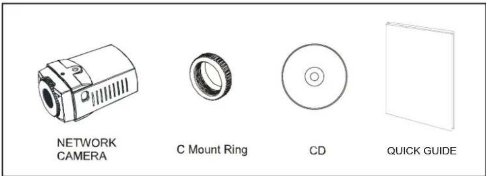
Unlike an analog camera, the NETWORK CAMERA enables users to easily see a real-time monitoring screen on Internet regardless of distance and locations, requiring no additional equipment. By using its dedicated program, many users are able to have an access to the NETWORK CAMERA at once or a single user can monitor various NETWORK CAMERAS at the same time. It also enables users to play, store and retrieve a monitoring image by using a PC. All the settings and real-time monitoring screens are also provided through an access to the web.
1.1 Components
1.2 NETWORK CAMERA'S External View and Port Description
1.2.1 Front View

natural_image
Top-down schematic of a circular mechanical component with concentric rings and mounting brackets (no text or symbols)1.2.2 Back View
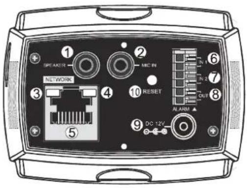
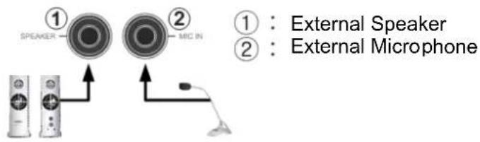
① : External Speaker
② : External Microphone
③ : LAN Operation Check LED
④ : LAN Connection Check LED
⑤ : RJ-45 Connector
⑥ : Alarm Input 1
⑦ : Alarm lutput2
⑧ : Alarm Output
⑨ : Power Input
⑩ : Reset Button
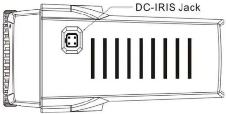
1.2.3 Side View
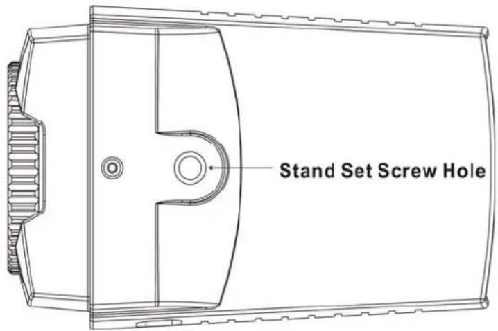
1.2.4 Top View
2. Network Camera Installation
2.1 Installation Order
Before operating this Network Camera, make sure to connect a network cable to power. Users can add an alarm cable or an audio cable there depending on what operation methods they choose.
As far as a camera-fixing stand is concerned, consult with an installer about its installation locations.
2.2 Network Connection
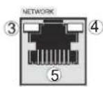
③ : LAN Operation Check LED
④ : LAN Connection Check LED
⑤ : RJ-45 Connection
The Network Camera supports the operation through the network. Therefore, it is necessary to connect a standard RJ-45 cable to it. Generally a cross cable is used for directly connection to PC, while a direct cable is used for connection to a hub.
2.2.1 Network Camera IP Assignment
Network Camera that is first connected to network basically has no IP address. So, it is necessary to allocate the IP address of network camera with an IP allocation program.
Open the program folder installed with the provided CD and execute "IP Setting Utility".
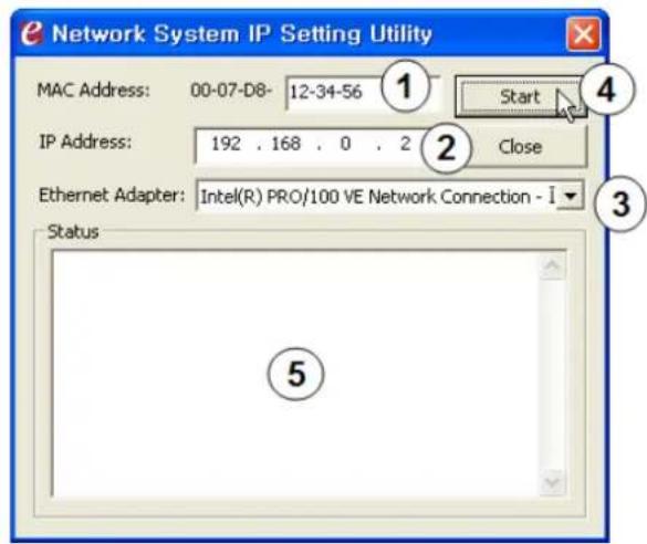
- MAC Address
- Enter MAC address of the product for IP input.
- IP Address
- Enter IP address to use.
- Ethernet Adapter
- In case there are several network cards, select a card to use for the operation of network camera.
- Start
- Allocate input IP to the network camera to use. When a completion message appears on
⑤Status window in several seconds or minutes, input completes its process. You can add additional IPs to other devices continuously.
2.3 Audio Connection
The NETWORK CAMERA enables users to send and receive a voice through the input/output module. Use it after connecting the port to the microphone and speaker, which have an amplifier function.
2.4 Alarm Connection
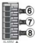
Users can control the alarm systems like a siren, an alarm and a warning light through two alarm inputs. For technical support necessary to use the alarm function, please contact the installer.
2.5 Power Connection
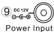
A stable power supply is required for the normal operation. The adapter with DC 12V/300mA or more is provided basically. It is recommended to use it along with an uninterruptible power supply (UPS) device regardless of its polarity.
2.6 Reset Button
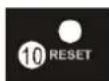
Reset Button
It connects the network camera in sources of electricity. When pressing reset buttons during 5 seconds, it starts a rebooting. When pressing reset buttons during 10 seconds, it starts a factory reset.
2.7 Network Camera Fixation
When it comes to the general installation of the Network Camera, users can fix the Network Camera on the stand by using a standard-sized screw hole on the top and bottom of the main body.
- Top Fixed Installation
: This method is mainly used to install a camera on the higher places away from the ground such as a ceiling or a dome camera stand.
●Bottom Fixed Installation
: This method is mainly used to install a camera on the close places to the ground like a wall or a general stand.
Besides there are many other methods to install a camera, but they differ slightly from each other according to installation places and operation methods. Therefore, please consult with the installer about the detailed installation methods.
3. Operation by Web Browser
3.1 Connecting the Network Camera by Web Browser
- Execute the Web Browser on the PC.
- Enter the camera address on the address window of the Web Brower and execute it. Ex) http://192.168.0.2/
(If the camera has no IP address or its IP address is wrong, users will fail to connect the camera. In this case, users will have to connect the camera by the Web Browser after entering the IP address with the IP Utility.) - If a security window for the ActiveX Controller installation appears, press the Confirm and install it.
- Refer to '2.2.1 Network Camera IP Assignment' section for detailed information.
- If it is not connected in the Internet, from the CD-ROM install the ActiveX Controller by manual operation.
- If it is not connected in the Internet, from the CD-ROM install the ActiveX Controller by manual operation.
3.2 Real-Time Monitoring
The monitoring screen comes in three screen modes like 640 X 480, 320 X 240, and 160 X 120. Users are allowed to select the most suitable one out of those modes. Please, adjust the mode in accordance with your PC specifications and monitoring purposes.
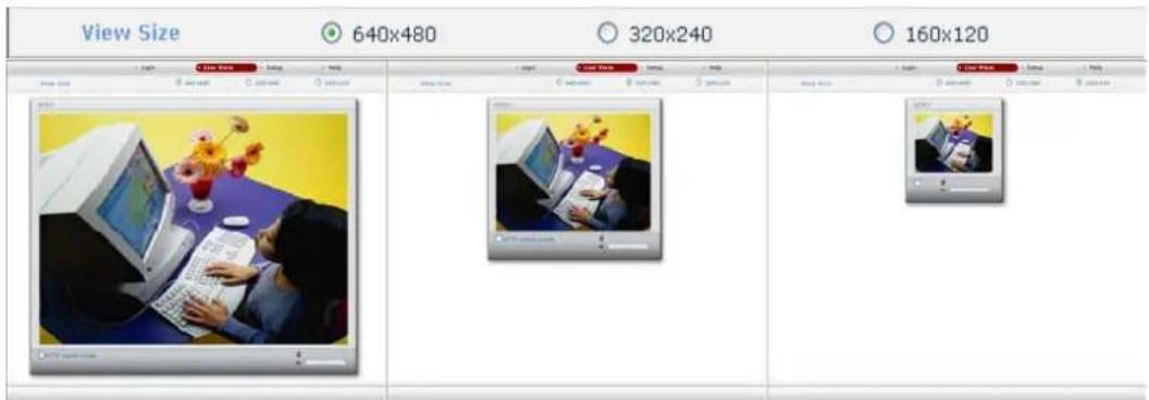
In case of real-time monitoring with the Web Browser, one NETWORK CAMERA will be connected to just one Web Browser. However, this case is not suitable for monitoring various screens at the same time. If users are to monitor various images at the same time, please contact your dealer.
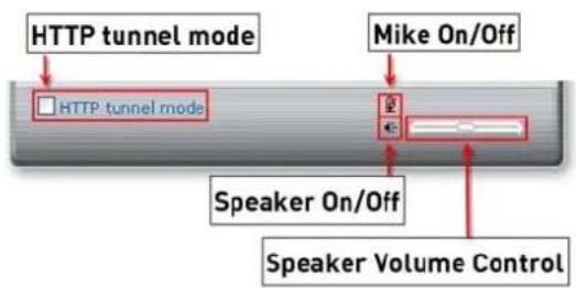
flowchart
graph TD
    A["HTTP tunnel mode"] --> B["HTTP tunnel mode"]
    C["Mike On/Off"] --> D["Speaker On/Off"]
    D --> E["Speaker Volume Control"]
□HTTP tunnel mode
When the screen is not indicated, check. (Notice: "unicast mode" only it is applied.)
If users are to control the volume of a microphone and speaker connected to a user PC, they should adjust the user PC volume regardless of the microphone and speaker volume control set in Network cameras.
3.3 NETWORK CAMERA Setting
Camera setting is divided into video, audio, alarm, and system settings. And the detailed screen will be provided for each setting.
3.3.1 Video Setting
The video setting is classified into Basic, MPEG-4, and Still Images. The Basic menu includes a setting menu for real-time monitoring. Its setting only is enough to complete a setting for viewing the monitoring screen. The detailed setting menu is able to perform screen sizing, filtering, compressibility, and brightness control.
Basic Setting
![Basic Image Appearance Resolution 640x480 Compression 2000 [×bps] Image Filter Strong Brightness 50 MPEG4 Video Stream Frame rate 30 Profile Simple Profile Bit-rate control Variable bit rate GOV size 30 [0 ... 60] Save Reset Help](/content/2026/05/816792/images/c382b598c058ec61eb9432f7cbaba8a55d2a39d11045e19e70f84ec3d95e08bf.jpg)
■ Image Appearance
Resolution
It enables users to determine a basic screen size when having an access through the Web Browser or PC program.
The screen size control comes in three modes like 640 X 480, 320 X 240, and 160 X 128. Users can reset the selected screen size anytime while monitoring the screen on a real-time basis.
Image filter
The image filter control enables users to reinforce the image quality in a strong or weak way. The default is "disabled."
Compression
When it is necessary to adjust a smooth transmission status according to network situations, users can increase the compressibility to carry out the network transmission stably. On the other hand, when it is necessary to maintain a detailed monitoring screen by enhancing the image quality, users can do so by decreasing the compressibility. In ease case, please adjust this function according to the network status and monitoring purposes. The default is 1500(Kbps).
Brightness
The screen brightness can be adjusted from 0 to 100 stages, and the default is 50. The brightness may differ depending on the equipment and PC monitor status.
■ MPEG4 Video Stream
Frame rate
Upon the real-time play, users should select a frame refresh rate per second. If the rate is high, the image will become smooth. On the other hand, if the rate is low, the image will not be natural but it can reduce a network load.
Bit-rate control
Variable bit rate (VBR): It refers to the type of using a variable bit rate (VBR). Increase a bit rate for the image with much motion, and decrease a bit rate for the image with little motion. The basic setting value is a VBR type.
Constant bit rate (CBR): Using a constant bit rate (CBR) may guarantee a stable play. However, if a large amount of data is not required, it may cause the waste of a transmission rate. If a large amount of data is required, it may cause the image quality to be decreased.
Profile
SP (Simple Profile) is available up to the CIF resolution and 384kbit/s.
ASP (Advanced Simple Profile) is available up to the 4CIF resolution and 8000kbit/s.
GOV size
The GOV size can be adjusted from 1 to 1000 stages, and the default is 30.
Enter the GOV (group of VOP) size. If users want to have a high quality of fast image one by one, please decrease the value. For the purpose of general monitoring, please do not change a basic value. Such act may cause a problem to the system performance. For the details of GOV setting, please contact the service center.
AE & AWB Setting
For more detailed settings, users can set the white balance and automatic exposure control. It is possible to designate the basic value according to the types of light or set it to a full automation mode.
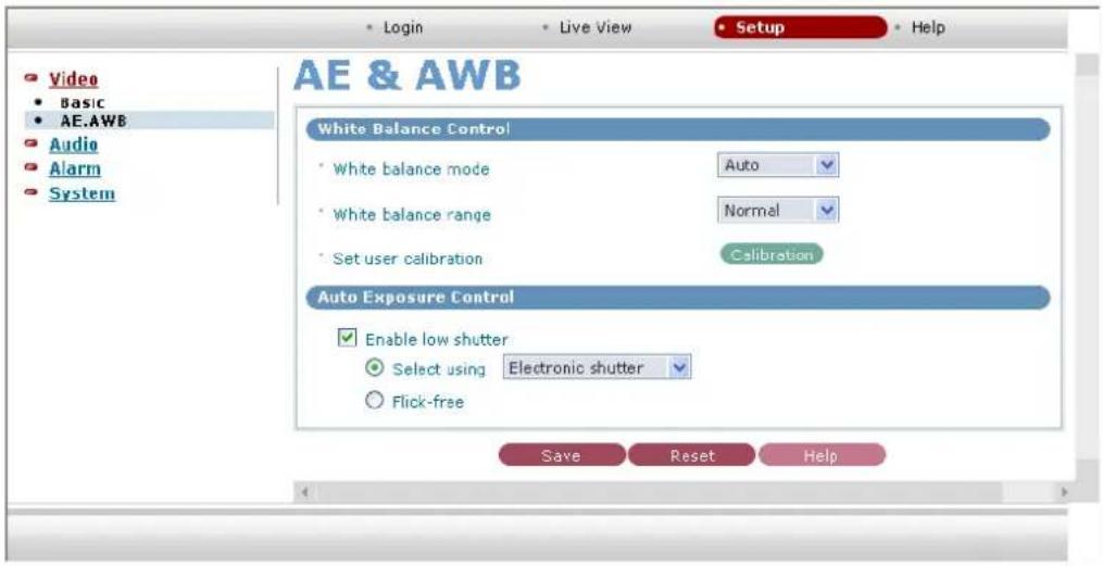
■ White Balance Control
White Balance Mode
When it comes to the White Balance Mode, users should select an illumination mode similar to that of general weather. Then, it can be set automatically. If users are not familiar with mode selection, please select the automatic mode.
White Balance range
This function is to prevent the White Balance from leaning to a certain color too much. If users want to prevent a certain color from getting thick too much at night or dark places, it would be effective to select the "Wide" mode. In general cases, please select the "Normal" mode. The default is "Normal" mode.
Set user calibration
Users are allowed to set the White Balance of their own. If users press the "Calibration" button after having a white background or a sheet of white paper in front of the NETWORK CAMERA, the White Balance will be adjusted.
■ Auto Exposure Control
Enable Low shutter : Users can use the Low Shutter mode in low light environments.
Select using
-Electronic shutter: For using manual lens.
-DC-IRIS: For using DC-IRIS lens.
Flicker-free : It removes flicker in the 50Hz power zone.( When it checks this, the shutter speed is fixed. So it uses 'Dc-Iris Lens', it promotes.)
3.3.2 Audio Setting
Basic Setting
Users can use a microphone and speaker by using the audio function.
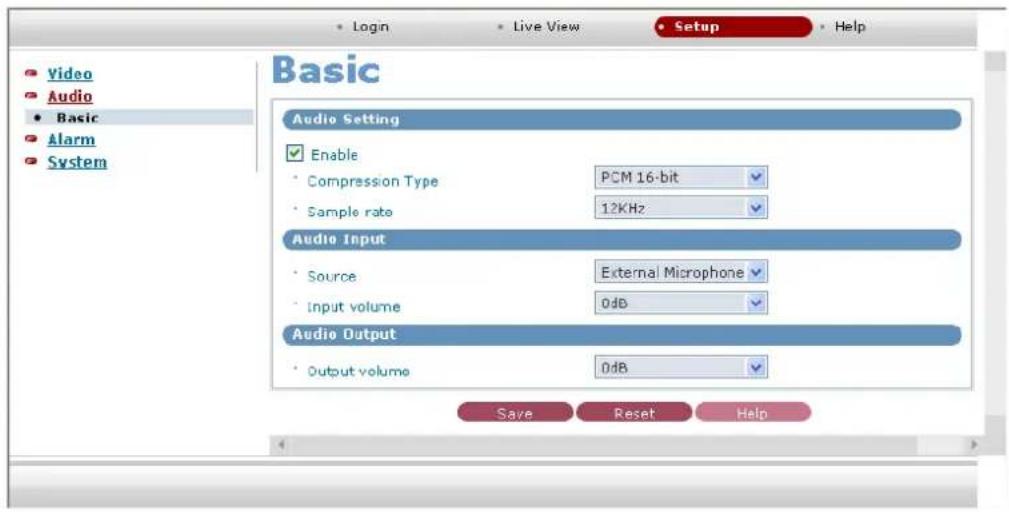
■ Audio Setting
Compression type
Users can increase a transmission rate or enhance a tone quality by selecting an audio compression mode. The PCM 16-bit implements the best tone quality, while the PCM 8-bit corresponds to that of radio sound.
Sample rate
If a sample rate is low, the tone quality will go down but the transmission rate will go up. If a sample rate is high, the tone quality will be better, but the transmission rate will drop. Please, adjust its rate in accordance with a network status or purposes.
Audio Input
Source
Users can select either MIC input or LINE input, but cannot use both at once.
Input Volume
Users can control the input volume by adjusting the microphone volume.
■ Audio Output
Output Volume
Users can control the output volume of the speaker connected to the NETWORK CAMERA.
3.3.3 Alarm Setting
Alarm In Setting
This function enables users to conduct the alarm input/output setting and event setting.
![Video Audio Alarm • Alarm In • Alarm Out • Event Setup System • Login • Live View • Setup • Help Alarm In Motion Detection Setting Enable • Sensitivity Very low • Motion dwell time 0 [0..6 sec] • Enable down fps Alarm IN Port 1 Setting Enable • Type NO • Alarm dwell time 50 [0..180] Alarm IN Port 2 Setting Enable • Type NO • Alarm dwell time 50 [0..180] Save Reset Help](/content/2026/05/816792/images/1d756e42096337e8b204324b697360b53643df111122db516cab4118f567635a.jpg)
■ Motion Detection Setting
Motion information is processed by splitting the screen into 64 areas. Each area can be selected by clicking with the mouse, and green point shown in the selected area. The area which uses the motion information as an event is shown green point, while the area which does not use the information is indicated empty.
Enable
Check this item when using the motion information.
-Sensitivity
This sets up the sensitivity for the motion detection.
-Motion dwelling time
This sets up the event dwelling time when a motion occurs. This can be set in the range of 0 \~ 6 seconds. When an event occurs, the motion icon at the upper right blinks in red for the preset time period. When another motion occurs during the motion event, the dwelling time is extended on the basis of the occurring time of the second event.
-Enable down FPS
This feature decreases frame rate to about 1 FPS when no motion event occurs, while operates with the frame rate set in this item when a motion event occurs.
■ Alarm IN Port 1 Setting
Type
Select the operation mode of the Alarm Input 1.
Select either 'N.O.(Normal Close)' or 'N.C.(Normal Open)'
Alarm dwelling time [0\~180]
Designate a running time for alarm occurrence. Select one out of 0 to 180 seconds.
■ Alarm IN Port 2 Setting
Type
Select the operation mode of the Alarm Input 2. Select either 'N.O.' or 'N.C.'
Alarm dwelling time [0\~180]
Designate a running time for alarm occurrence. Select one out of 0 to 180 seconds.
Alarm Out Setting
Upon the alarm occurrence, this function enables users to receive a mailing or ftp service to the mobile phones or mail address designated by users.
![Video Audio Alarm • Alarm In • Alarm Out • Event Setup System • Login • Live View • Setup • Help Alarm Out SMTP(EMail) Setting Enable • Sender admin@company.com • Receiver list emily@company.com ilexis@company.com taylor@company.com jessica@company.cc olivia@company.com grace@company.com destiny@company.com brooke@company.cc page@company.com irene@company.com • EMail test Test FTP & JPEG Setting • FTP Settings :: Enable • Server name or IP 133.155.26.36 Passive Mode • Port 21 • Remote directory \emergency\ • Lhasname admin Anonymous login • PasswordPassword •••••• • JPEG Settings : • Pre event Time: 0 [1~5 sec] FPS: 0 [1~2 fps] • Post event Time: 0 [1~15 sec] FPS: 0 [1~2 fps] Note) if "Time" and "FPS" are equal to 0, it mean that send only one JPG image on event. • Image size 320x240 • Color Color • Base name image.jpg • Additional suffix None Date/time Sequence number Save Reset Help](/content/2026/05/816792/images/079b6cebc57f90acaaddba80c9087b44f3cb05870e1ce7424eba6ccf0b6b51fc.jpg)
■ SMPT(eMail) Setting
Sender : Enter an eMail address to send a mail.
Receiver list: Enter up to 10 eMail addresses to receive a mail.
Email test: Enter an eMail address to test for sending a mail.
Tset button : Test for sending a mail with a value entered.
■ FTP & JPEG Setting
-FTP Settings
□ Enable
Checks to activate the FTP function.
Sender name or IP: Enters the FTP IP address or host name to be received.
Port: Enters the port number of FTP to be received.
Remote Directory: Enters the location for saving the file of FTP to be received.
Username: Enters the user's account when connecting to FTP.
Password: Enters the user password for connecting to FTP.
-JPEG Settings
Sets up the creation condition, screen size, color and name of JPEG file to be sent to FTP.
Pre event: Creates the JPEG file of chapter 1\~5 for 1\~2 seconds before the event is generated.
Post event: Creates the JPEG file of chapter 1\~15 for 1\~2 seconds after the event is generated.
Image size: Selects the size of JPEG file to be created among 160X120 and 320X240.
Color: Selects the color or B&W of JPEG file to be created.
Base name: Write in the basic name of file to be created.
Except for the basic name, It is possible to add supplementary names for discriminating multiple files.
Additional suffix: Selects one among date, time and the number of sequence created.
- None: Do not add supplementary names.
- Date Time: Adds the date and time when the file was created behind the basic name.
- Sequence: Adds the number in sequence of file creation behind the basic name.
Event Setup
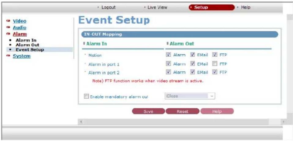
IN-OUT Mapping
By connecting the Alarm OUT operations to the events occurred from the Alarm IN, users can send an eMail or FTP Server.
Alarm IN - Alarm IN comes in Motion, Alarm in port 1 and Alarm in port 2.
Alarm OUT
Alarm: Operate the equipment connected to the Alarm OUT port to the events occurred from the Alarm IN.
eMail: Send an email to events occurred from the Alarm IN.
FTP: Sends the captured picture to FTP by the event which occurs from Alarm input. □Enable mandatory alarm out: Enable alarm control to open/close contact.
3.3.4 System Setting
Users Setting
This NETWORK CAMERA's Authority Policy
1. Anonymous User Access Permit Mode
This mode enables any anonymous users to have an access to the NETWORK CAMERA to monitor and set it.
2. Anonymous User Access Denial Mode
Upon selecting this mode, the NETWORK CAMERA operates in two authority groups. And it also requires a log-in process when users are to have an access to the NETWORK CAMERA to change a screen monitoring or setting.
1) Administrator Authority Group (admin)
It enables administrators to change the screen monitoring and setting of the NETWORK CAMERA. In addition, this authority allows only one user to have an access to the camera at once.
2) General User Authority Group (user)
It enables users to simply use a screen monitoring function. It disables users to change the NETWORK CAMERA setting but allows them to have a multiple access at the same time.
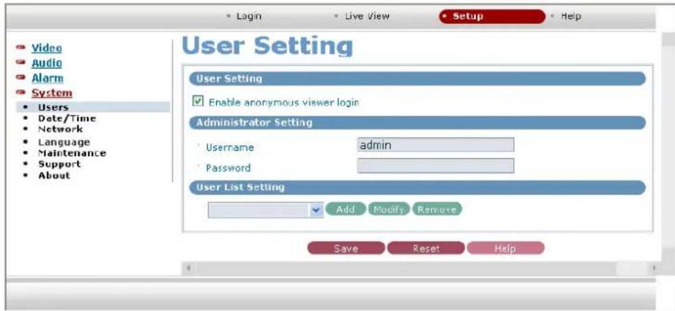
User setting
Enable anonymous viewer login: Check it when users do not want to use the camera without the user account.
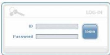
When using the user account, users have to try login at every access.
■ Admin Setting
User name: Enter a user name for the administrator use.
Password: Enter the password for the administrator use.
■ User List Setting
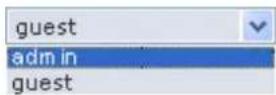
Show a registered user account.
-Add User
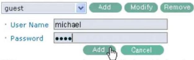
Enter a user name and password to be added, and register them by pressing the "Add" button.
-Modify User Information
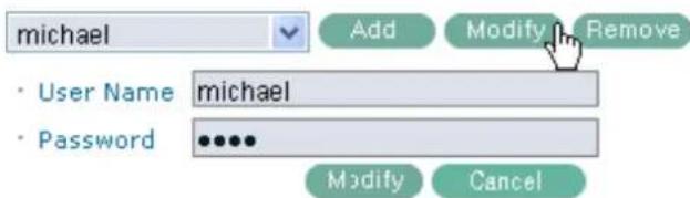
After selecting a user to be corrected and changing its name and password, press the 'modify' button to reflect the corrected information.
- Delete User Account

After selecting a user to be deleted, delete it by pressing the "Remove" button.
Date & Time Setting
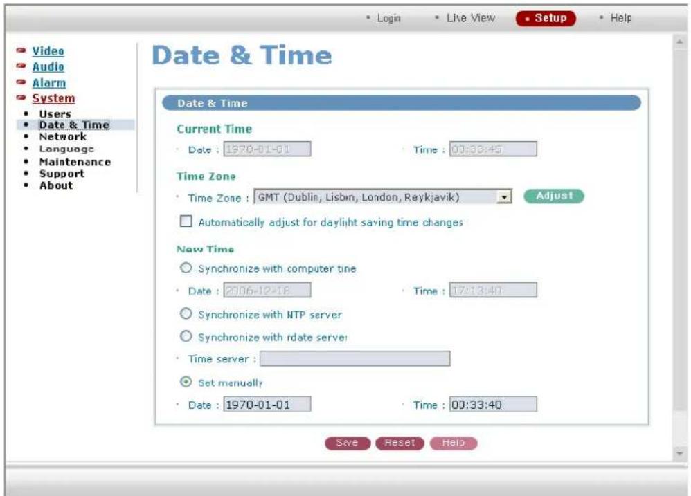
Date & Time
Current Time: Indicate a current time.
- Date: Indicate a current day, month, and year.
• Time: Indicate a current day, month, and year.
New Time
•Time Zone: Select a time zone to be used.
□Automatically adjust for daylight saving time changes:
Check it if users are to apply the Summer Time.
Time zone
◎Synchronize with computer time: Synchronize the time with that of a current user computer.
◎Synchronize with NTP server: Synchronize the time with that of the NTP server. Receive the time information from the NTP (RFC2030) server.
◎Synchronize with date server: Enter the Time Server address to be synchronized. Receive the time information from the Time Server that complies with the Time protocol (RFC868).
- Set manually: Users enter a current time directly.
- Date: Enter a current day, month, and year.
•Time: Enter a current day, month, and year.
Network Setting
Setting in regard to network can be executed. Settings for IP, DNS, Host Name, Port, and Network traffic can be established, along with setting for DDNS and RTP.
Basic Setting
Basic settings for IP, DNS, Host Name, and Port are possible, and possibly works as a adjustment role in reducing the overload of network bandwidth in use, by applying Network traffic capability.
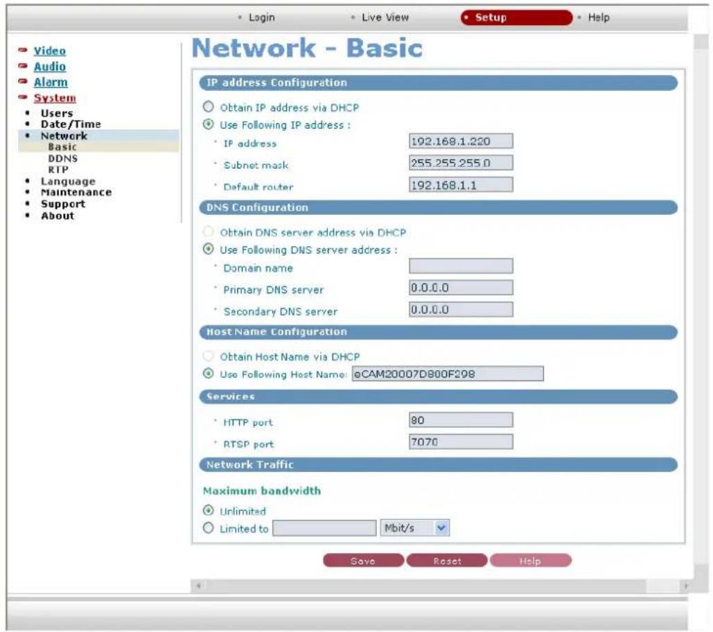
■ IP address Configuration
- Obtain IP address via DHCP: Obtain an IP through the DHCP automatically.
- Use Following IP address: Users enter a NETWORK CAMERA IP directly.
DNS Configuration
Obtain DNS server address via DHCP: Obtain the DNS information through the DHCP.
- Use Following DNS server address: Users enter the DNS information directly.
- Domain name: Enter a domain name to be used.
- Primary DNS server: Enter the first domain name server.
- Secondary DNS server: Enter the second domain name server address.
■ Host Name Configuration
Obtain Host Name via DHCP: Obtain a Network Camera name from the DHCP automatically.
- Use Following Host Name: Users enter a camera name directly.
Services
- HTTP port: Enter a port to receive a service through the HTTP. Default Port Number is '80'.
- RTSP port: Enter a port to receive a service through the RTSP. Default Port Number is '7070'.
■ Network traffic - Maximum bandwidth
Set a limitation on user network resources by designating the maximum bandwidth.
- Unlimited: Selected if not influenced by a network-related program or equipment without a limitation on the network bandwidth.
- Limited to: In case of sharing other network programs or equipment, it is possible to set a limitation on the maximum bandwidth in the unit of Mbit/s or kbit/s.
DDNS Setting
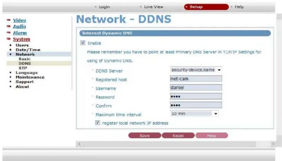
■ Internet Dynamic DNS
When using the high-speed Internet with the telephone or cable network, users can operate the NETWORK CAMERA even on the floating IP environment in which IPs are changed at every access.
Users should receive an account and password by visiting a DDNS service like "http://www.dyndns.com/."
□ Enable
Check to get DDNS service to be available.
- DDNS Server: Select the ddns server.
- Registered host: Enter a host address.
-Username: Enter an ID to access to the DDNS server. - Password: Enter a password to be used for accessing the DDNS server.
- Confirm: Enter a password again to confirm it.
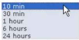
•Maximum time interval: Set a time interval to synchronize with the DDNS server.
- Register local network IP address: Register a NETWORK CAMERA IP address to the DDNS server.
RTP Setting
Have a setting for sending and receiving an audio or video on a real-time basis.
![Network - RTP Stream RTP after camera start-up Send to DHCP server IP VIEW Send to (Client) IP 0.0.0.0 Use RTP destination Port 5000 [1024..65532; even values only] Do not send Enable multi stream Send to secondary client ip 0.0.0.0 Use RTP destination port 5000 [1024..65532; even values only] Frame rate 10 fps Note) If you check multi stream function, MPEG profile will be changed to Advanced Simple Profile. RTSP/RTP Settings RTP destination IP Disable multicast Enable multicast: Multicast destination IP 0.0.0.0 [empty means self-generated] RTP port 5000 [1024..65532; even values only] RTP TTL 1 [1..255] Save Reset Help](/content/2026/05/816792/images/9f01211fe344c070f41f899c55aa81198e2f8b423c3dacc7374c745bca8eb840.jpg)
■ Stream RTP after Network Camera start-up
Enter a destination IP and Port to send stream automatically through the RTP while the Network Camera has booting.
- Send to DHCP server IP: Send stream to the DHCP server.
- Send to (Client) IP: Send stream to other certain destination addresses.
Use RTP destination Port: Available from 1024 to 65532, and the default is 5000.
- Do not send: Do not send a stream automatically.
□ Enable multi stream
Check it to send data for the purpose of saving them into an external extension storage right after the Network Camera operates.
-Send to secondary client ip: Enter an IP address of the external extension storage.
-Use RTP destination port: Enter a Port number of the external extension storage. The Port number to be used is [1024 \~ 65532].
-Frame rate: Indicate a frame rate that is sent to the external extension storage when the multi stream works.
Once the multi stream function is checked, the MPEG profile setting will be changed to the Advanced Simple Profile.
■ RTSP/RTP settings
Perform a multicast setting to send a video and audio to multiple users.
(Up to 10 users)
RTP destination IP
◎Disable Multicast: Do no use the multicast.
- Enable Multicast: Use the multicast.
Multicast destination IP: Enter an IP between 224.0.0.0 and 239.255.255.255. Although it is empty, an IP will be entered automatically.
RTP port: Enter a value between 1024 and 65532.
RTP TTL: Enter a value between 1 and 255. If a network status is smooth, enter a lower value. On the other hand, if a network status is poor, enter a higher value. When there are many Network cameras or users, a higher value may cause a heavy load to the network. For a detailed setting, please consult with a network manager.
Language
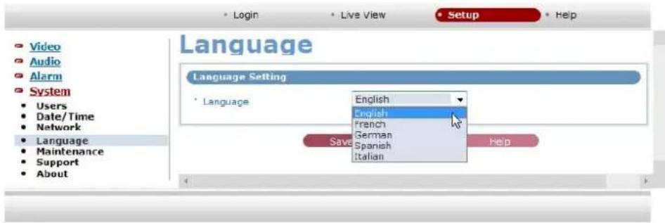
•Language
It will be able to select a user language. The type of language it will be able to select is the English, the French, the German, the Spanish and the Italian.
Maintenance
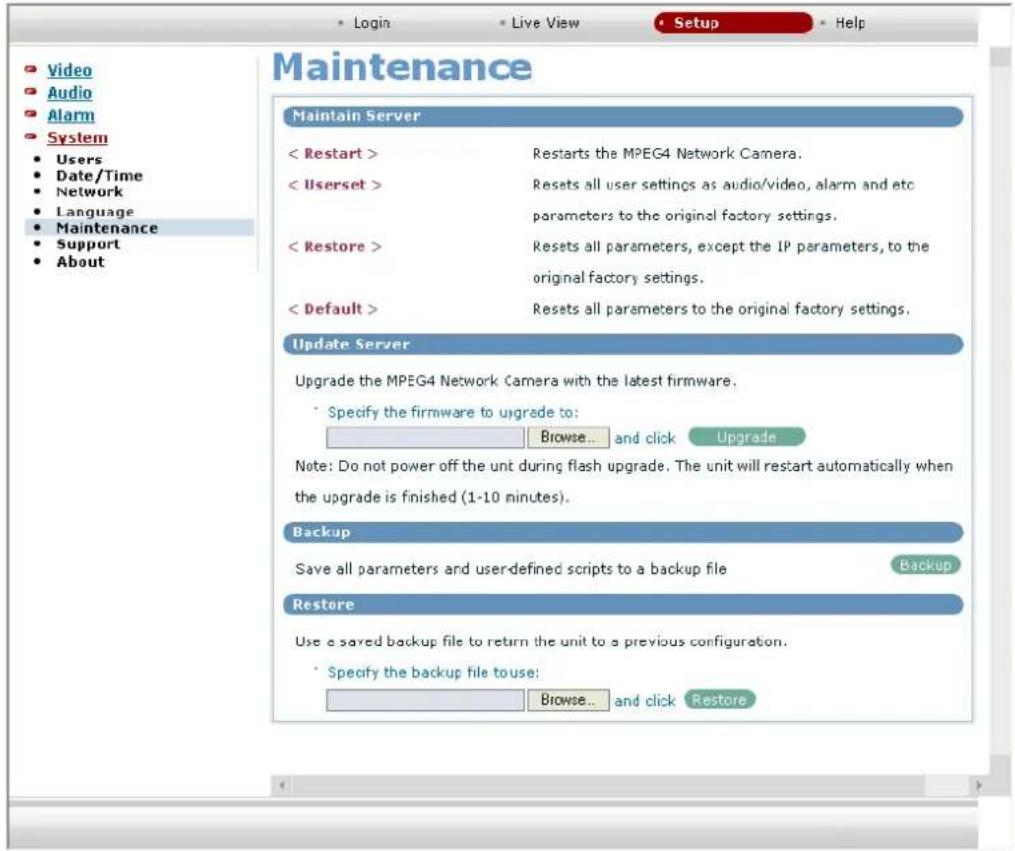
■ Maintain Server
< Restart > Restart the NETWORK CAMERA.
< Userset > Initialize a user setting value of audio/video, alarm, etc.
< Default >Restore all the setting values to a basic value.
■ Upgrade Server
Carry out the upgrade by importing an upgrade file and pressing the 'Upgrade' button. During the upgrade, do not turn off the power of the NETWORK CAMERA.
Backup
Save a setting value that users enter to the NETWORK CAMERA, to a user PC.
Restore
Import and apply a setting value saved to a user PC.
Program Support Information
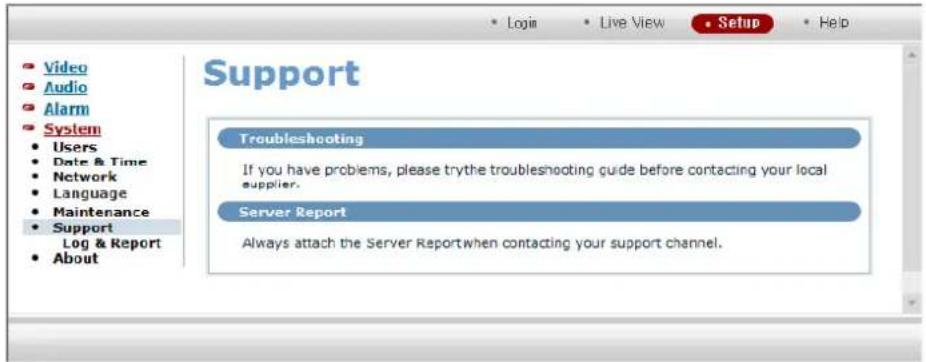
Troubleshooting
When problems occur during operation, please consult with an installer.
Server Report
If its support is requested, please attach a server report.
Log & Report
Users can check the system log and server report.
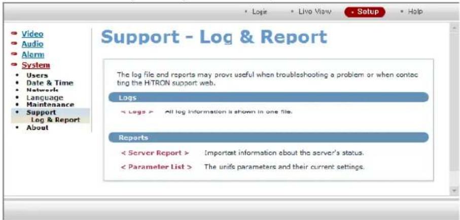
Logs
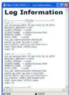
Users can check the log for Network Camera operation by clicking the < Logs >.
Reports
![Log Information Windows version=1.1-279 * - System information Linux version 2.4.18-1 (rodtimes korn32 breast b5) (p) * - Optime 15:17:03 up 5 days, 15:17, load average: 0.03, 0.01 * - Mounted filesystems dev/rot / ext2 ro w 0.0 none /pros/ptg/ no 0.0 none /dev/shm/trpfs ru 0.0 none /mp-trpfs ru 0.0 dev/mtdbook-5 mrdw/ rfa, radative 0.0 * - Running processes PID Id: vMizpa Stat Command 1 rst 266 S 2 rst 266 S 3 rst 1Wk [kshofrop_CPU] 4 rst 1Wk [kswapd] 5 rst 1Wk [ksh] 6 rst 1Wk [kupdated] 7 rst 1Wk [mtbook] 10 rst 266 S [fta-end] 90 rst 266 S [nmbcdlog] m 0](/content/2026/05/816792/images/a36633861fef9e7b8795c8ab1868cfb7f8376431b0461c4cbb59c3eeb76c59eb.jpg)
Users can check a server report by clicking the < Server Report >.
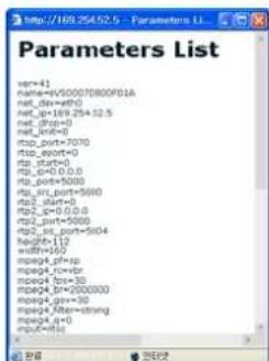
Users can check a parameter by clicking the < Parameter List >.
Program Information
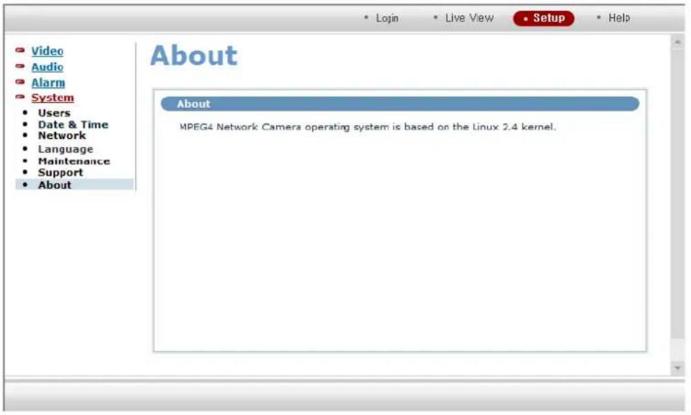
The following website will provide the support information for the NETWORK CAMERA system information and operation.
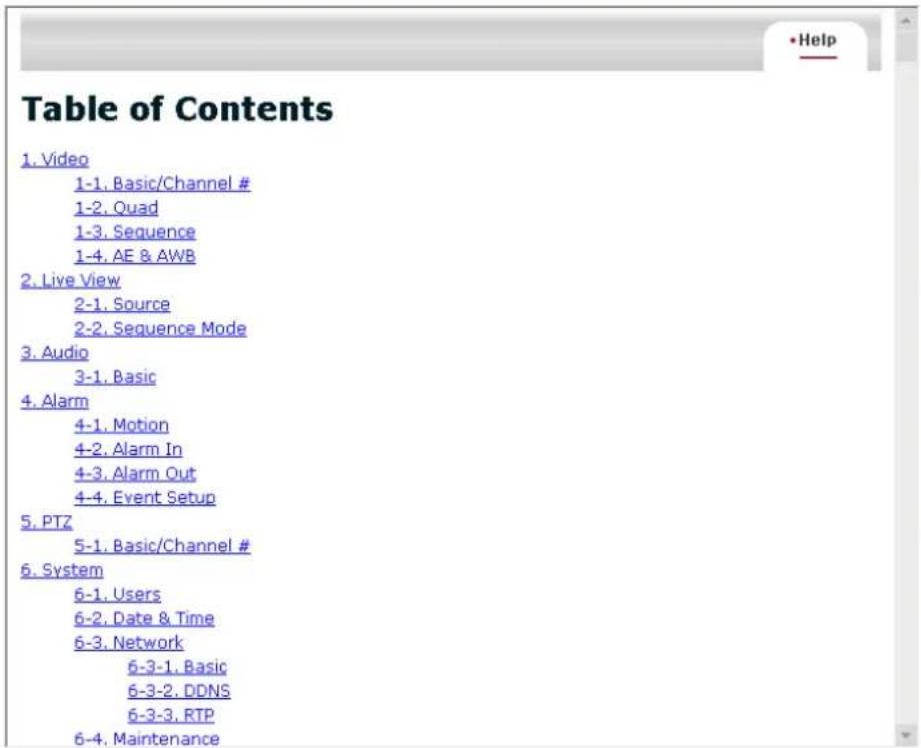
3.4 Help
The Help information window will be provided as a popup window so that users can open and read it without a need for log-in. It will offer a description on setting and Help page by which users can manipulate the Network Camera without a reference to the manual.
4. Appendix
4.1 Troubleshooting
If problems occur, verify the installation of the camera with the instructions in this manual and with other operating equipment. Isolate the problem to the specific piece of equipment in the system and refer to the equipment manual for further information.
| PROBLEM AREA TO CHECK | |
| No video | Verify that power is connected to all pieces of equipment in the system.Verify that the power switches are in the ON position.Check the video connections. (see page 4) |
| Poor video quality. | Check the latest Video Card Driver update of the user PC. |
| Frame rate decrease. | Change current value more lower resolution, compression rate and frame rate. |
| A connection is cut-off at short intervals. | Check network traffic and contact with network administrator. |
4.2 Preventive Maintenance
Preventive maintenance allows detection and correction of minor that faults before they become serious and cause equipment failure.
Every three-month, perform the following maintenance.
- Inspect all connection cables for deterioration or other damage.
- Clean components with a clean damp cloth.
- Verify that all the mounting hardware is secure.
4.3 Product Specifications
Video
Resolution 640 X 480 / 320 X 240 / 160 X 120
Frame rate Max 30 fps @ 640 X 480 resolution
CCD 1/4" Progressive scan R,G,B CCD sensor
Video compression MPEG4 SP and ASP
Compression option Variable bit rate / Constant bit rate
Lens mount C mount, CS mount
Video out RJ-45(1ea)
Audio
Codec PCM 16/8-bit, Full duplex
Mic in External mic in (ø 3.5 mm Jack 1ea)
Speaker out External speaker out (ø 3.5 mm Jack 1ea)
Alarm
Alarm in 2 inputs
Alarm out 1 output (relay)
Motion detection Adjustable with size, position, sensitivity and time
Alarm message transmission e-Mail, ftp
Network
Protocols UDP / TCP/IP / DHCP / HTTP / RTP / RTSP / SMTP /
DDNS
Ethernet 10Base-T/100Base-T
Interface
Connector RJ-45, UTP Cable
System Requirements for client S/W
Operation System Microsoft Windows 2000/XP
CPU Intel Pentium IV 2.0GHz or higher
Memory 512MB or more
VGA 1024 X 768, 32bit color DirectX 9.0c or higher
HDD 80GB or higher
Web browser Microsoft Internet Explorer version 6.0
Power
Power supply DC 12V, 3W
Control
Minimum illumination 1 Lux
Exposure Automatic DC iris / Electronic shutter / AGC
Shutter speed 1/100,000 \~ 1/30 sec
Low shutter 1/30 \~ 1/15 sec
White balance Automatic / Manual
Time
Real-Time Clock (RTC) 0.01 sec / 0.1 sec / 1 sec, minutes, hours, day, date, month, year and century
Other
Operating Temperature 0^ C \~ +45°C
Size 72.9W * 54H * 109.3D (mm)
Weight 290g
UK
Mitsubishi Electric Europe B.V.
UK Branch Office
Visual Information Systems Division
Travellers Lane Hatfield Herts AL10
8XB
Telephone: +44 (1707)-278 684
Fax: +44 (1707)-278 541
GERMANY
Mitsubishi Electric Europe B.V.
German Branch Office
Electric Visual Systems
Gothaer Str. 8 40880 Ratingen
Germany
Telephone: +49 (2102)-486 9250
Fax: +49 (2102)-486 7320
SPAIN
Mitsubishi Electric Europe B.V.
Spanish Branch Office
Ctra. De Rubi, 76-80 Apdo.420
French Branch Office
Italian Branch Office
Paracelso 12, 20041 Agrate Brianza, Italy
Telephone: +39 (039)-605 31
Fax: +39 (039)-605 3214
The Netherlands
Mitsubishi Electric Benelux
A Division of Mitsubishi Electric Europe
B.V.
A Division of Mitsubishi Electric Europe
B.V.
Westgate Business Park, Ballymount,
Dublin 24. Ireland
Telephone: +353 (1)-419 8800
Fax: +353 (1)-419 8895
- Warning
- IMPORTANT SAFEGUARDS
- TABLE OF CONTENTS
- Production Introduction ...... 1
- NETWORK CAMERA Installation 3
- Operation by Web Browser 5
- Appendix ...... 24
- Product Introduction
- Components
- NETWORK CAMERA'S External View and Port Description
- Front View
- Back View
- Side View
- Top View
- Network Camera Installation
- Installation Order
- Network Connection
- Network Camera IP Assignment
- Audio Connection
- Alarm Connection
- Power Connection
- Reset Button
- Reset Button
- Network Camera Fixation
- Operation by Web Browser
- Connecting the Network Camera by Web Browser
- Real-Time Monitoring
- NETWORK CAMERA Setting
- Video Setting
- Basic Setting
- ■ Image Appearance
- Resolution
- Image filter
- Compression
- Brightness
- ■ MPEG4 Video Stream
- Frame rate
- Bit-rate control
- Profile
- GOV size
- AE & AWB Setting
- ■ White Balance Control
- White Balance Mode
- White Balance range
- Set user calibration
- ■ Auto Exposure Control
- Select using
- Audio Setting
- ■ Audio Setting
- Audio Input
- ■ Audio Output
- Alarm Setting
- Alarm In Setting
- ■ Motion Detection Setting
- Enable
- -Sensitivity
- -Motion dwelling time
- -Enable down FPS
- ■ Alarm IN Port 1 Setting
- ■ Alarm IN Port 2 Setting
- Alarm Out Setting
- ■ SMPT(eMail) Setting
- ■ FTP & JPEG Setting
- Event Setup
- IN-OUT Mapping
- System Setting
- Users Setting
- Anonymous User Access Permit Mode
- Anonymous User Access Denial Mode
- 1) Administrator Authority Group (admin)
- 2) General User Authority Group (user)
- User setting
- ■ Admin Setting
- ■ User List Setting
- -Add User
- -Modify User Information
- - Delete User Account
- Date & Time Setting
- Date & Time
- Time zone
- Network Setting
- ■ IP address Configuration
- DNS Configuration
- ■ Host Name Configuration
- Services
- ■ Network traffic - Maximum bandwidth
- DDNS Setting
- ■ Internet Dynamic DNS
- □ Enable
- RTP Setting
- ■ Stream RTP after Network Camera start-up
- □ Enable multi stream
- ■ RTSP/RTP settings
- Language
- •Language
- Maintenance
- ■ Maintain Server
- ■ Upgrade Server
- Backup
- Restore
- Program Support Information
- Troubleshooting
- Server Report
- Log & Report
- Logs
- Reports
- Program Information
- Help
- Appendix
- Troubleshooting
- Preventive Maintenance
- Product Specifications
- Video
- Audio
- Alarm
- Network
- System Requirements for client S/W
- Power
- Control
- Time
- Other
- UK
- GERMANY
- SPAIN
- The Netherlands
Brand : MITSUBISHI
Model : NM-C110
Category : Security Camera