
NetVanta 5660 - Router Adtran - Free user manual and instructions
Find the device manual for free NetVanta 5660 Adtran in PDF.


| Product Type | Carrier Ethernet Services Router |
| Brand | Adtran |
| Model | NetVanta 5660 |
| Form Factor | 1U, 19-inch or 23-inch rack-mountable |
| Dimensions (H x W x D) | 1.72 in x 17.22 in x 11.5 in (4.37 cm x 43.74 cm x 29.21 cm) |
| Input Voltage | 48 VDC |
| Processor and Memory | 512 MB RAM, 128 MB Flash |
| Ethernet Interfaces | 5 Gigabit Ethernet: 4 combo (RJ-45/SFP) + 1 fiber-only SFP |
| Modular WAN Options | Quad/Octal SHDSL (Annex A/B), Quad VDSL2 (Annex A/B) |
| Routing Protocols | eBGP/iBGP, OSPF, RIP (v1/v2), GRE, IGMPv2, VRRP |
| Security Features | Stateful firewall, NAT, ACLs, IPSec VPN (optional), TACACS+, RADIUS |
| Management | AOS CLI, SNMPv3, SSH, Telnet, NTP, Syslog |
| Layer 3 QoS | Low Latency Queuing, WFQ, DiffServ, NetFlow 9 |
| Ethernet Features | IEEE 802.1Q VLAN, 802.1p, MEF 9/14, Q-in-Q |
| Fault and Performance Mgmt | IEEE 802.3ah EFM OAM, ITU-T Y.1731 CFM/PM |
| Operating Temperature | -25°C to 70°C (-13°F to 158°F) without AC PSU; 0°C to 40°C with AC |
| Relative Humidity | Up to 95% noncondensing |
| Agency Approvals | FCC Part 15 Class B, UL 60950-1, CE, RoHS |
| LED Indicators | STAT (status), FAN, and per Ethernet link/activity |
| Mounting Options | Rack, wall, or tabletop |
Frequently Asked Questions - NetVanta 5660 Adtran
User questions about NetVanta 5660 Adtran
0 question about this device. Answer the ones you know or ask your own.
Ask a new question about this device
Download the instructions for your Router in PDF format for free! Find your manual NetVanta 5660 - Adtran and take your electronic device back in hand. On this page are published all the documents necessary for the use of your device. NetVanta 5660 by Adtran.
USER MANUAL NetVanta 5660 Adtran
NetVanta 4660/5660 Hardware Installation Guide
17004660F1/F3 NetVanta 4660 Chassis
17005660F1 NetVanta 5660 Chassis
17406368F1 NetVanta Carrier Ethernet Quad SHDSL EFM Module, Annex A
17406368F3 NetVanta Carrier Ethernet Quad SHDSL EFM Module, Annex B
17806368F1 NetVanta Carrier Ethernet Octal SHDSL EFM Module, Annex A
17806368F3 NetVanta Carrier Ethernet Octal SHDSL EFM Module, Annex B
17406369F1 NetVanta Carrier Ethernet Quad VDSL2 EFM Module, Annex A
17406369F3 NetVanta Carrier Ethernet Quad VDSL2 EFM Module, Annex B
Trademarks
Any brand names and product names included in this manual are trademarks, registered trademarks, or trade names of their respective holders.
To the Holder of the Manual
The contents of this manual are current as of the date of publication. ADTRAN reserves the right to change the contents without prior notice.
In no event will ADTRAN be liable for any special, incidental, or consequential damages or for commercial losses even if ADTRAN has been advised thereof as a result of issue of this publication.
Software Licensing Agreement
Each ADTRAN product contains a single license for ADTRAN-supplied software. Pursuant to the Licensing Agreement, you may: (a) use the software on the purchased ADTRAN device only and (b) keep a copy of the software for backup purposes. This Agreement covers all software installed on the system, as well as any software available on the ADTRAN website. In addition, certain ADTRAN systems may contain additional conditions for obtaining software upgrades.

Changes or modifications to this unit not expressly approved by the party responsible for compliance could void the user's authority to operate the equipment.

901 Explorer Boulevard
P.O. Box 140000
Huntsville, AL 35814-4000
Phone: (256) 963-8000
Copyright © 2014 ADTRAN, Inc.
All Rights Reserved.
Printed in U.S.A.
Conventions

Notes provide additional useful information.

Cautions signify information that could prevent service interruption or damage to the equipment.

Warnings provide information that could prevent injury or endangerment to human life.
Safety Instructions
When using your telephone equipment, please follow these basic safety precautions to reduce the risk of fire, electrical shock, or personal injury:
- Do not use this product near water, such as a bathtub, wash bowl, kitchen sink, laundry tub, in a wet basement, or near a swimming pool.
- Avoid using a telephone (other than a cordless type) during an electrical storm. There is a remote risk of shock from lightning.
- Do not use the telephone to report a gas leak in the vicinity of the leak.
- Use only the power cord, power supply, and batteries indicated in the manual. Do not dispose of batteries in a fire. They may explode. Check with local codes for special disposal instructions.
- The socket-outlet shall be installed near the equipment and shall be easily accessible.
If any of the following conditions occur, unplug the product from the electrical outlet and replace the part or contact your qualified service personnel:
- The power cable, extension cable, or plug is damaged.
- An object has fallen into the product.
- The product has been exposed to water.
- The product has been dropped or damaged.
- The product does not operate correctly when you follow the operating instructions.

These units contain no user-serviceable parts. They should only be serviced by qualified service personnel.

Additional safety guidelines, such as Waste Electrical and Electronic Equipment (WEEE), are given in the document NetVanta Safety and Regulatory Information available online at http://supportforums.adtran.com.
Save These Important Safety Instructions
FCC-Required Information
FCC regulations require that the following information be provided in this manual:
- This equipment complies with Part 68 of Federal Communications Commission (FCC) rules and requirements adopted by America's Carriers Telecommunications Association (ACTA). Each registered interface has a label that contains, among other information, a product identifier in the format US:AAAEQ##TXXXX. If requested, provide this information to the telephone company.
- If this equipment causes harm to the telephone network, the telephone company may temporarily discontinue service. If possible, advance notification is given; otherwise, notification is given as soon as possible. The telephone company will advise the customer of the right to file a complaint with the FCC.
- The telephone company may make changes in its facilities, equipment, operations, or procedures that could affect the proper operation of this equipment. Advance notification and the opportunity to maintain uninterrupted service are given.
- If experiencing difficulty with this equipment, please contact ADTRAN for repair and warranty information. The telephone company may require this equipment to be disconnected from the network until the problem is corrected, or it is certain the equipment is not malfunctioning.
- This unit contains no user-serviceable parts.
- This equipment is designed to connect to the telephone network or premises wiring using an FCC-compatible modular jack, which is compliant with Part 68 and requirements adopted by ACTA.
- The following information may be required when applying to the local telephone company for leased line facilities:
| Part Number | RegistrationNumber Service Type | REN/SOC FIC USOC | |||
| 17406368F1 | US:HDCDLNAN7806368F1 SHDSL 9.0F Metallic RJ-48C | ||||
| 17806368F1 | |||||
| 17406369F1 | US:HDCDL01B7406369F1 | VDSL2 | 0.0B | 02LS2 | RJ-11 |
-
The ringer equivalence number (REN) is useful in determining the quantity of devices you may connect to your telephone line and still have all of those devices ring when your number is called. In most areas, the sum of the RENs of all devices should not exceed five. To be certain of the number of devices you may connect to your line as determined by the REN, call your telephone company to determine the maximum REN for your calling area.
-
This equipment may not be used on coin service provided by the telephone company. Connection to party lines is subject to state tariffs. Contact your state public utility commission or corporation commission for information.
FCC Radio Frequency Interference Statement
This equipment has been tested and found to comply with the limits for a Class A digital device, pursuant to Part 15 of the FCC rules. These limits are designed to provide reasonable protection against harmful interference when the equipment is operated in a commercial environment. This equipment generates, uses, and can radiate radio frequency energy and, if not installed and used in accordance with the instruction manual, may cause harmful interference to radio frequencies. Operation of this equipment in a residential area is likely to cause harmful interference in which case the user will be required to correct the interference at his own expense.
Electromagnetic Compatibility (EMC) Table
| NetVanta Module P/N and Name NetVanta 4660 NetVanta 5660 | ||
| 17406368F1 Carrier Ethernet Quad SHDSL EFM Module, Annex A FCC Part 15 | Class BEN 300 386 | FCC Part 15 Class BEN 300 386 |
| 17406368F3 Carrier Ethernet Quad SHDSL EFM Module, Annex B FCC Part 15 | Class BEN 300 386 | FCC Part 15 Class BEN 300 386 |
| 17806368F1 Carrier Ethernet Octal SHDSL EFM Module, Annex A FCC Part 15 | Class BEN 300 386 | FCC Part 15 Class BEN 300 386 |
| 17806368F3 Carrier Ethernet Octal SHDSL EFM Module, Annex B FCC Part 15 | Class BEN 300 386 | FCC Part 15 Class BEN 300 386 |
| 17406369F1 Carrier Ethernet Quad VDSL2 EFM Module, Annex A FCC Part 15 | Class BEN 300 386 | FCC Part 15 Class BEN 300 386 |
| 17406369F3 Carrier Ethernet Quad VDSL2 EFM Module, Annex B FCC Part 15 | Class BEN 300 386 | FCC Part 15 Class BEN 300 386 |
Industry Canada Compliance Information
This product meets the applicable Industry Canada technical specifications.
The Ringer Equivalence Number (REN) is an indication of the maximum number of devices allowed to be connected to a telephone interface. The termination of an interface may consist of any combination of devices subject only to the requirement that the sum of the RENs of all the devices not exceed five.
Canadian Emissions Requirements
This digital apparatus does not exceed the Class B limits for radio noise emissions from digital apparatus as set out in the interference-causing equipment standard entitled “Digital Apparatus,” ICES-003 of the Department of Communications.
Toll Fraud Liability
Be advised that certain security risks are inherent in the use of any telecommunications or networking equipment, including but not limited to, toll fraud, Denial of Service (DoS) attacks, loss or theft of data, and the unauthorized or illegal use of said equipment. ADTRAN OFFERS NO WARRANTIES, EITHER EXPRESSED OR IMPLIED, REGARDING THE PREVENTION, DETECTION, OR DETERRENCE OF TOLL FRAUD, NETWORKING ATTACKS, OR UNAUTHORIZED, ILLEGAL, OR IMPROPER USE OF ADTRAN EQUIPMENT OR SOFTWARE. THEREFORE, ADTRAN IS NOT LIABLE FOR ANY LOSSES OR DAMAGES RESULTING FROM SUCH FRAUD, ATTACK, OR IMPROPER USE, INCLUDING, BUT NOT LIMITED TO, HUMAN AND DATA PRIVACY, INTELLECTUAL PROPERTY, MATERIAL ASSETS, FINANCIAL RESOURCES, LABOR AND LEGAL COSTS. Ultimately, the responsibility for securing your telecommunication and networking equipment rests with you, and you are encouraged to review documentation regarding available security measures, their configuration and implementation, and to test such features as is necessary for your network.
Third-Party Software
The software included in this product contains copyrighted software that is licensed under the GNU General Public License (GPL). For a list of third-party software and their licenses, go to http://www.adtran.com/software/EULA. You can obtain the complete corresponding source code of such software components from ADTRAN for a period of three years after our last shipment of this product by sending a money order or check for \$5 to:
ADTRAN, Inc, P.O. Box 933638, Atlanta, GA 31193-3638
Please write GPL Source for product NetVanta 4660/5660 in the memo line of your payment.
This offer is valid to anyone in receipt of this information.
Service and Warranty
For information on the service and warranty of ADTRAN products, visit the Support section of the ADTRAN website at http://www.adtran.com.
Table of Contents
Introduction 15
Physical Description 16
Shipping Contents 16
NetVanta 4660/5660 Series Front Panel Design 17
LED Descriptions 18
Features and Specifications 19
NetVanta 4660 19
NetVanta 5660 19
Physical Interfaces 19
Security 20
DSL Features 21
Ethernet Features 21
Fault and Performance Management 21
Environment 22
Physical and Input Power 22
Agency Approvals 22
Option Modules 23
Network Modules 24
Unit Installation 30
Tools Required 30
Mounting Options 31
Connecting Ground to the Unit 33
Supplying Power to the Unit 33
Installing Network Modules 33
Appendix A. Connector Pin Definitions.... 35
Base Unit Pinouts 35
Network Module Pinouts 37
List of Figures
Figure 1. NetVanta 4660/5660 Series Front Panel Layout 17
Figure 2. NetVanta Carrier Ethernet Quad SHDSL EFM Module, Annex A 24
Figure 3. NetVanta Carrier Ethernet Quad SHDSL EFM Module, Annex B 25
Figure 4. NetVanta Octal SHDSL EFM Network Module, Annex A 26
Figure 5. NetVanta Carrier Ethernet Octal SHDSL EFM Module, Annex B 27
Figure 6. NetVanta Carrier Ethernet Quad VDSL2 EFM Module, Annex A 28
Figure 7. NetVanta Carrier Ethernet Quad VDSL2 EFM Module, Annex B 29
Figure 8. Wallmount Installation 32
Figure 9. Network Module Installation .... 34
List of Tables
Table 1. Front Panel Status LED Behaviors ..... 18
Table 2. NetVanta Carrier Ethernet Quad SHDSL EFM Module, Annex A LED Behaviors. . . . . . . . 24
Table 3. NetVanta Carrier Ethernet Quad SHDSL EFM Module, Annex B LED Behaviors.....25
Table 4. NetVanta Octal SHDSL EFM Network Module, Annex A LED Behaviors ..... 26
Table 5. NetVanta Carrier Ethernet Octal SHDSL EFM Module, Annex B LED Behaviors ..... 27
Table 6. NetVanta Carrier Ethernet Quad VDSL EFM Module, Annex A LED Behaviors ..... 28
Table 7. NetVanta Carrier Ethernet Quad VDSL2 EFM Module, Annex B LED Behaviors ..... 29
Table A-1. CONSOLE Port Pinouts 35
Table A-2. SFP Slot Pinouts 35
Table A-3. 1000Base-T Gigabit Ethernet Port Pinouts 36
Table A-4. T4 Port Pinouts 36
Table A-5. Quad SHDSL EFM Pinouts 37
Table A-6. Octal SHDSL EFM (Ports 1 through 4) Pinouts....37
Table A-7. Octal SHDSL EFM (Ports 5 through 8) Pinouts....37
Table A-8. Quad VDSL2 Pinouts 38
1. INTRODUCTION
This hardware installation guide describes the NetVanta 4660/5660 Series units' physical characteristics, lists their features and specifications, introduces basic functionality, and provides installation instructions in the following sections:
• Physical Description on page 16
• Features and Specifications on page 19
- Option Modules on page 23
• Unit Installation on page 30
For additional information on shipping contents, mounting options, network module installation, and power the unit, refer to the following sections:
• Shipping Contents on page 16
- Mounting Options on page 31
• Supplying Power to the Unit on page 33
• Installing Network Modules on page 33
For information on NetVanta 4660/5660 Series configuration for a specific application, refer to the configuration guides provided on the ADTRAN Support Community. For details on the command line interface (CLI), refer to the AOS Command Reference Guide. All other related documents are also available online at http://supportforums.adtran.com.
2. PHYSICAL DESCRIPTION
The NetVanta 4660 is an integrated Layer 2 and Layer 3 carrier Ethernet services router providing a universal edge device supporting any mix of Layer 3 IP Virtual Private Network (VPN), Layer 2 VPN (E-LINE/E-LAN), and Internet access services. The NetVanta 4660 eases the transition from Layer 3 IP VPN services delivered over TDM-based Point-to-Point Protocol (PPP) or Frame Relay circuits to Ethernet-based services delivered over broadband access networks (EoX, VDSL2, GPON, PPP over Ethernet (PPPoE)).
The NetVanta 5660 builds on the architecture of the NetVanta 4660 and is designed to allow service providers to provide Gigabit throughput for both Layer 2 and Layer 3 services. Service providers can deliver higher bandwidth services to their customers for mobile devices as well as reliable and fast connectivity for cloud-based applications.
All NetVanta 4660/5660s include an option module slot for future VDSL and SHDSL modules. There are four 10/100/1000Base-T combination (copper or small form factor pluggable (SFP)) local area network (LAN) interfaces – all with carrier Ethernet functionality – and one fiber-only interface.
In the event that a single EFM loop fails, the NetVanta 4660/5660 will continue to operate on the remaining loop, providing redundancy. Once the failed loop is operational again, the NetVanta 4660/5660 will automatically detect its availability and will automatically recover to the original configuration.
Network Modules Supported
The main base unit supports interchangeable network modules. The network modules currently available in this series include the following:
• Carrier Ethernet Quad SHDSL EFM Module, Annex A
- Carrier Ethernet Quad SHDSL EFM Module, Annex B
• Carrier Ethernet Octal SHDSL EFM Module, Annex A
• Carrier Ethernet Octal SHDSL EFM Module, Annex B
• Carrier Ethernet Quad VDSL2 EFM Module, Annex A
- Carrier Ethernet Quad VDSL2 EFM Module, Annex B
SFP Module Slots
The NetVanta 4660/5660 Series has five small form-factor pluggable (SFP) slots that accept a number of industry standard SFP modules. The SFP modules provide Gigabit Ethernet fiber connectivity for high-speed uplinks. For a list of supported SFP modules, visit the ADTRAN website at http://www.adtran.com.
Shipping Contents
Each NetVanta 4660/5660 Series units are shipped in their own cardboard shipping carton. Open each carton carefully, and avoid deep penetration into the carton with sharp objects.
After unpacking the unit, inspect it for possible shipping damage. If the equipment has been damaged in transit, immediately file a claim with the carrier and contact ADTRAN Customer Service (refer to the Support page on the ADTRAN website at http://www.adtran.com/support).
NetVanta 4660/5660 Series Domestic Shipping Contents
Domestic shipments of the NetVanta 4660/5660 Series include the following items:
• NetVanta 4660/5660 base unit
- Set of two 19-inch rack mounting brackets
- Set of 4 rubber mounting feet
- Six mounting screws
- Quick start guide
NetVanta 4660/5660 Series International Shipping Contents
International shipments of the NetVanta 4660/5660 Series include the following items:
• NetVanta 4660/5660 base unit
- Set of two ETSI/23-inch rack mounting brackets
- Set of 4 rubber mounting feet
- Six mounting screws
- Quick start guide
NetVanta 4660/5660 Series Front Panel Design
The NetVanta 4660/5660 Series front panel is shown below along with a description of all connectors and interfaces.

Figure 1. NetVanta 4660/5660 Series Front Panel Layout
Power Connector
The power connector, labeled 48VDC, provides connection for a 48 VDC power source. Please refer to Supplying Power to the Unit on page 33 for connection details.
Status LEDs
The STAT LED indicates the unit's status. The FAN LED reflects the status of the fan. The GIG 0/1 through GIG 0/5 LEDs reflect the status of the 10/100/1000Base-T Ethernet interfaces. See the Table 1 on page 18 for LED behaviors.
CONSOLE Interface
The CONSOLE interface is an EIA-232 serial port (DCE), which provides for local management and configuration (via a DB-9 female connector). See Table A-1 on page 35 for the CONSOLE interface pinouts.

Connection directly to an external modem requires a cross-over cable.
10/100/1000Base-T Ethernet Interfaces
The GIG 0/1 port consists of one SFP slot for connectivity over fiber. The status LED is located above the interface.
The GIG 0/2 through GIG 0/5 ports consist of one RJ-45 and one SFP slot for connectivity over fiber. (Use either the RJ-45 connector or the SFP slot. The fiber slot has precedence.) See Table A-3 on page 36 for the Ethernet interface pinouts. The status LEDs, are located above each interface.
1 PPS 50 ohm Phase Synchronization Measurement Interface
The phase synchronization interface, labeled 1 PPS OUT, provides a one pulse per second output which can be used to connect to measurement equipment.
• Period: 1 second +/-1 ppm
- Rise Time: 5 ns (maximum)
• Voh: 5.5 V (maximum), 1.2 V (minimum)
• Vol: 0.3 V (maximum), -0.3 V (minimum)
- Pulse Width: 200 ns (minimum), 500 ms (maximum), 10 us (typical)
Timing Interface
The RJ-45 interface, labeled T4, is provided for timing output in both T12 and E12 modes.
Option Slot
The option slot accepts a variety of network modules (refer to Option Modules on page 23).
LED Descriptions
The following table describes LED activity for the NetVanta 4660/5660 Series.
Table 1. Front Panel Status LED Behaviors
| LED Color Indication | ||
| STAT | Off Unit is not receiving power. | |
| Green (flashing) | The unit is powering up. On power up the STAT LED flashes rapidly for five seconds, during which time the user can escape to boot mode from the CONSOLE port. | |
| Green (solid) The power is on and self-test passed. | ||
| Red (solid) The power is on, but the self-test failed or the application code could not be booted. | ||
| STAT | Off Unit is not receiving power. | |
| FAN | Green (solid) Both fans are functioning properly. | |
| Amber (solid) Only one fan is functioning. | ||
| Red (solid) Neither fan is functioning. | ||
| GIG 0/1 through GIG 0/5 | Off Port is inactive or administratively disabled. | |
| Green (solid) The link is up. | ||
| Amber (flashing) There is activity on the link. | ||
3. FEATURES AND SPECIFICATIONS
NetVanta 4660
- Universal edge device supporting modular Layer 2/3 Carrier Ethernet services with Gigabit combo interfaces
NetVanta 5660
- Same functionality as the NetVanta 4660 with the addition of Gigabit line rate for both Layer 2 and Layer 3 routing
Physical Interfaces
Ethernet
- Four 10/100/1000Base-T dual copper or SFP and one fiber-only SFP for a total of five Gigabit Ethernet interfaces
– All ports included in chassis
– All Ethernet interfaces include carrier Ethernet functionality
- Full duplex
- RJ-45 connectors
• Supports 802.1q VLAN trunking
Modular WAN Options
• Quad SHDSL, Annex A and B
• Octal SHDSL, Annex A and B
• Quad VDSL2, Annex A and B
Processor and Memory
• RAM: 512 MB
- Flash: 128 MB
Protocols
• eBGP/iBGP
- Open Shortest Path First (OSPF)
- RIP (v1 and v2)
- GRE
• I G M P v 2
- Layer 3 Backup
- Multi-VRF CE
- PPP
• P P P o E
- PAP and CHAP
- Multihoming
• VRRP
Management and Utilities
- AOS command line interface (CLI)
- ADTRAN n-Command ® Managed Service Platform (MSP)
- Simple Network Management Protocol version 3 (SNMPv3)
- SYSLOG logging
- Telnet, craft/console port, SSH, ping, trace route, NTP
- TCL scripting
- Policy statistics
- Email alerts (SMTP)
LEDs
- Status
- F a n
• GIG 0/1 through GIG 0/5
Layer 3 Quality of Service (QoS)
- Low Latency Queuing, Weighted Fair Queuing (WFQ), and Class-based WFQ
- DiffServ packet marking and recognition
• Frame Relay fragmentation - Traffic monitoring (NetFlow 9)
Security
Firewall
• Stateful inspection firewall
• Denial of service (DoS) protection
- Access control lists (ACLs)
- Application level gateways (ALGs)
Network Address Translation
• Network address translation (NAT) (1:1, many:1) and 1:1 port translation
• NAT-compatible SIP ALG
Secure Management
- Multi-level access control
• TACACS+
• RADIUS AAA - SSH CLI and SSL GUI
Content Filtering
- Inherent URL filter
- Top website reports
- Integration with Websense®
Virtual Private Network (VPN) (Optional)
• IPSec Tunnel Mode: Tunnels 1,000
- Encryption: DES, 3DES, and AES
-
Authentication Mechanisms:
-
XAUTH Secure ID
- X.509 digital certificates
- DSS Signatures
– Preshared keys
DSL Features
- Variable rate bonding for the SHDSL loops
• Automatic failover and recovery - Plug-and-play automatic line detection
Ethernet Features
- IEEE 802.1p priority marking
- IEEE 802.1d dynamic/transparent bridging
- IEEE 802.1Q virtual local area network (VLAN) tagging
• IEEE 802.3u Ethernet
• MEF 9/14 certified EPL, EVPL
Ethernet Services Support
- Priority queuing of traffic based on VLAN priority
– Supports eight class of service (CoS) queues
- Per UNI port, CE VLAN ID (C-Tag) and/or CE VLAN P-bits, DSCP fields
- Single stack VLAN and double stack VLANs (Q-in-Q)
- Manipulation based on 802.1p and DSCP fields
- STAG TPID provisioning supports 802.1ad and 802.1Q standards
- Port-based service support
• Services Scale and Flexibility
- Configurable EtherType and TPID for service flexibility
- VLAN IDs 2 to 4090; EVC configurable in the range of 1 to 4090
- Ingress policers (tr3CM), CIR and EIR settings to 64 kbps granularity, configurable burst through EBS, CBS settings
– Egress shaping per port - Up to 8 shapers per interface
Fault and Performance Management
- IEEE 802.3ah EFM standard
• ITU-T Y.1731 CFM, PM
• IEEE 802.3ah Link OAM
• ITU-T Y.1731 CFM, PM
• Supports OAM management status and loopback messaging
• Network monitoring enhancements
Environment
- Operating Temperature without AC power supply: -25°C to 70°C (-13°F to 158°F)
- Operating Temperature with AC power supply: 0°C to 40°C (32°F to 104°F)
- Storage Temperature: -40°C to 85°C (-40°F to 185°F)
- Relative Humidity: Up to 95 percent, noncondensing
Physical and Input Power
- Chassis: 1U high, 19-inch or 23-inch rack mountable metal enclosure
- Dimensions: 1.72-inch H x 17.22-inch W x 11.5-inch D
- Input Voltage: 48 VDC
Agency Approvals
• FCC Part 15, Class B
• UL 60950-1, Second Edition
• EN 60950, Second Edition, A1, A11, A12
• AS/NZS 60950.1
• CSA C22.2 No. 60950-1, Second Edition
• C E M a r k
• ETSI 300
• R o H S
4. OPTION MODULES
The NetVanta 4660/5660 Series supports several option modules designed to meet a variety of networking requirements. The option modules include plug-in network modules.
Network modules are cards that plug directly into the option module slot located on the front of the base unit. These cards provide the following types of interfaces:
• NetVanta Carrier Ethernet Quad SHDSL EFM Module, Annex A (P/N 17406368F1) on page 24
• NetVanta Carrier Ethernet Quad SHDSL EFM Module, Annex B (P/N 17406368F3) on page 25
• NetVanta Carrier Ethernet Octal SHDSL EFM Module, Annex A (P/N 17806368F1) on page 26
• NetVanta Carrier Ethernet Octal SHDSL EFM Module, Annex B (P/N 17806368F3) on page 27
• NetVanta Carrier Ethernet Quad VDSL2 EFM Module, Annex A (P/N 17406369F1) on page 28
• NetVanta Carrier Ethernet Quad VDSL2 EFM Module, Annex B (P/N 17406369F3) on page 29
This section describes each module, providing individual card specifications and features. Refer to Appendix A on page 35 for pinout information. Installing Network Modules on page 33 provides information on card installation.
Network Modules
NetVanta Carrier Ethernet Quad SHDSL EFM Module, Annex A (P/N 17406368F1)
The NetVanta Carrier Ethernet Quad SHDSL EFM Module, Annex A (shown in Figure 2) provides a WAN-SHDSL EFM interface. See Table A-5 on page 37 for the Quad SHDSL EFM connector pinouts.
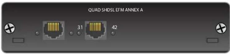
Figure 2. NetVanta Carrier Ethernet Quad SHDSL EFM Module, Annex A Features and Specifications
Operating Mode
• Line termination (CO)
• Network termination (CPE)
SHDSL Interface
• Four 2-wire eSHDSL loops
• Supported Standards: ITU-T G.991.2 Annex A
• IEEE 802.3ah EFM bonding
MEF compliant
Clock Source
• CPE Operating Mode: Network
• CO Operating Mode: Internal
Compliance
• EMC - see Electromagnetic Compatibility (EMC) Table on page 6.
- UL/CUL 60950-1
• ACTA/FCC Part 68
IC CS-03
- RoHS compliant
Environmental
- Operating Temperature: -25°C to 70°C (-13°F to 158°F)
• Storage Temperature: -40°C to 85°C ( -40°F to 185°F )
• Relative Humidity: Up to 95 percent, noncondensing
Physical
• Dimensions: 6.75-inch W x 6.59-inch D
Table 2. NetVanta Carrier Ethernet Quad SHDSL EFM Module, Annex A LED Behaviors
| LED Color Indication | ||
| SHDSL 1 through 4 | Off SHDSL loop is administratively shut down. | |
| Green (flashing) SHDSL loop is training. | ||
| Green (solid) SHDSL loop is trained and EFM group is established. | ||
| Amber (flashing) SHDSL loop is trained but EFM group is not established. | ||
| Amber (solid) SHDSL loop is in test. | ||
| Red (flashing) SHDSL loop is in handshake process. | ||
| Red (solid) SHDSL loop connection failure. | ||
NetVanta Carrier Ethernet Quad SHDSL EFM Module, Annex B (P/N 17406368F3)
The NetVanta Carrier Ethernet Quad SHDSL EFM Module, Annex B (shown in Figure 3) provides a WAN-SHDSL EFM interface. See Table A-5 on page 37 for the Quad SHDSL EFM connector pinouts.

Figure 3. NetVanta Carrier Ethernet Quad SHDSL EFM Module, Annex B Features and Specifications
Operating Mode
• Line termination (CO)
• Network termination (CPE)
SHDSL Interface
• Four 2-wire eSHDSL loops
• Supported Standards: ITU-T G.991.2
Annex B
• IEEE 802.3ah EFM bonding
- MEF compliant
Clock Source
• CPE Operating Mode: Network
• CO Operating Mode: Internal
Compliance
• EMC - see Electromagnetic Compatibility (EMC) Table on page 6.
• UL/CUL 60950-1
• AS/ACIF S043
• IEC 60950-1, Second Edition
• EN 60950-1, Second Edition
• AS/NZS 60950.1
- RoHS compliant
Environmental
- Operating Temperature: -25°C to 70°C (-13°F to 158°F)
- Storage Temperature: -40°C to 85°C (-40°F to 185°F)
- Relative Humidity: Up to 95 percent, noncondensing
Physical
• Dimensions: 6.75-inch W x 6.59-inch D
Table 3. NetVanta Carrier Ethernet Quad SHDSL EFM Module, Annex B LED Behaviors
| LED Color Indication | ||
| SHDSL 1 through 4 | Off SHDSL loop is administratively shut down. | |
| Green (flashing) SHDSL loop is training. | ||
| Green (solid) SHDSL loop is trained and EFM group is established. | ||
| Amber (flashing) SHDSL loop is trained but EFM group is not established. | ||
| Amber (solid) SHDSL loop is in test. | ||
| Red (flashing) SHDSL loop is in handshake process. | ||
| Red (solid) SHDSL loop connection failure. | ||
NetVanta Carrier Ethernet Octal SHDSL EFM Module, Annex A (P/N 17806368F1)
The NetVanta Carrier Ethernet Octal SHDSL EFM Module, Annex A (shown in Figure 4) provides a WAN-SHDSL EFM interface. See Table A-6 on page 37 and Table A-7 on page 37 for the Octal SHDSL EFM connector pinouts.

Figure 4. NetVanta Octal SHDSL EFM Network Module, Annex A Features and Specifications
Operating Mode
• Line termination (CO)
• Network termination (CPE)
SHDSL Interface
• Eight 2-wire eSHDSL loops
• Supported Standards: ITU-T G.991.2 Annex A
• IEEE 802.3ah EFM bonding
- MEF compliant
Clock Source
• CPE Operating Mode: Network
• CO Operating Mode: Internal
Compliance
• EMC - see Electromagnetic Compatibility (EMC) Table on page 6.
- UL/CUL 60950-1
• ACTA/FCC Part 68
- IC CS-03
- RoHS compliant
Environmental
- Operating Temperature: -25°C to 70°C (-13°F to 158°F)
• Storage Temperature: -40°C to 85°C ( -40°F to 185°F ) - Relative Humidity: Up to 95 percent, noncondensing
Physical
• Dimensions: 6.75-inch W x 6.59-inch D
Table 4. NetVanta Octal SHDSL EFM Network Module, Annex A LED Behaviors
| LED Color Indication | ||
| SHDSL 1 through 8 | Off SHDSL loop is administratively shut down. | |
| Green (flashing) SHDSL loop is training. | ||
| Green (solid) SHDSL loop is trained and EFM group is established. | ||
| Amber (flashing) SHDSL loop is trained but EFM group is not established. | ||
| Amber (solid) SHDSL loop is in test. | ||
| Red (flashing) SHDSL loop is in handshake process. | ||
| Red (solid) SHDSL loop connection failure. | ||
NetVanta Carrier Ethernet Octal SHDSL EFM Module, Annex B (P/N 17806368F3)
The NetVanta Carrier Ethernet Octal SHDSL EFM Module, Annex B (shown in Figure 5) provides a WAN-SHDSL EFM interface. See Table A-6 on page 37 and Table A-7 on page 37 for the Octal SHDSL EFM connector pinouts.

Figure 5. NetVanta Carrier Ethernet Octal SHDSL EFM Module, Annex B Features and Specifications
Operating Mode
• Line termination (CO)
• Network termination (CPE)
SHDSL Interface
• Eight 2-wire eSHDSL loops
• Supported Standards: ITU-T G.991.2 Annex B
• IEEE 802.3ah EFM bonding
- MEF compliant
Clock Source
• CPE Operating Mode: Network
• CO Operating Mode: Internal
Compliance
• EMC - see Electromagnetic Compatibility (EMC) Table on page 6.
- UL/CUL 60950-1
AS/ACIF S043
• IEC 60950-1, Second Edition
• EN 60950-1, Second Edition
• AS/NZS 60950.1
- RoHS compliant
Environmental
• Operating Temperature: -25°C to 70°C (-13°F to 158°F)
• Storage Temperature: -40°C to 85°C (-40°F to 185°F)
• Relative Humidity: Up to 95 percent, noncondensing
Physical
• Dimensions: 6.75-inch W x 6.59-inch D
Table 5. NetVanta Carrier Ethernet Octal SHDSL EFM Module, Annex B LED Behaviors
| LED Color Indication | ||
| SHDSL 1 through 8 | Off SHDSL loop is administratively shut down. | |
| Green (flashing) SHDSL loop is training. | ||
| Green (solid) SHDSL loop is trained and EFM group is established. | ||
| Amber (flashing) SHDSL loop is trained but EFM group is not established. | ||
| Amber (solid) SHDSL loop is in test. | ||
| Red (flashing) SHDSL loop is in handshake process. | ||
| Red (solid) SHDSL loop connection failure. | ||
NetVanta Carrier Ethernet Quad VDSL2 EFM Module, Annex A (P/N 17406369F1)
The NetVanta Carrier Ethernet Quad VDSL2 EFM Module, Annex A (shown in Figure 6) provides a WAN-VDSL interface. See Table A-8 on page 38 for the Quad VDSL2 connector pinouts.

Figure 6. NetVanta Carrier Ethernet Quad VDSL2 EFM Module, Annex A Features and Specifications
Operating Mode
• Line termination (CO)
• Network termination (CPE)
SHDSL Interface
• Four 2-wire VDSL loops
• Supported Standards: ITU-T G.991.2
Annex A
• IEEE 802.3ah EFM bonding
- MEF compliant
Clock Source
• CPE Operating Mode: Network
• CO Operating Mode: Internal
Compliance
• EMC - see Electromagnetic Compatibility (EMC) Table on page 6.
- UL/CUL 60950-1
• ACTA/FCC Part 68
- IC CS-03
- RoHS compliant
Environmental
- Operating Temperature: -25°C to 70°C (-13°F to 158°F)
- Storage Temperature: -40°C to 85°C (-40°F to 185°F)
- Relative Humidity: Up to 95 percent, noncondensing
Physical
• Dimensions: 6.75-inch W x 6.59-inch D
Table 6. NetVanta Carrier Ethernet Quad VDSL EFM Module, Annex A LED Behaviors
| LED Color Indication | ||
| SHDSL 1 through 4 | Off VDSL loop is administratively shut down. | |
| Green (flashing) VDSL loop is training. | ||
| Green (solid) VDSL loop is trained and EFM group is established. | ||
| Amber (flashing) VDSL loop is trained but EFM group is not established. | ||
| Amber (solid) VDSL loop is in test. | ||
| Red (flashing) VDSL loop is in handshake process. | ||
| Red (solid) VDSL loop connection failure. | ||
NetVanta Carrier Ethernet Quad VDSL2 EFM Module, Annex B (P/N 17406369F3)
The NetVanta Carrier Ethernet Quad VDSL2 EFM Module, Annex B (shown in Figure 7) provides a WAN-VDSL interface. See Table A-8 on page 38 for the Quad VDSL2 connector pinouts.

Figure 7. NetVanta Carrier Ethernet Quad VDSL2 EFM Module, Annex B Features and Specifications
Operating Mode
• Line termination (CO)
• Network termination (CPE)
SHDSL Interface
• Four 2-wire VDSL loops
• Supported Standards: ITU-T G.991.2 Annex B
• IEEE 802.3ah EFM bonding
- MEF compliant
Clock Source
• CPE Operating Mode: Network
• CO Operating Mode: Internal
Compliance
• EMC - see Electromagnetic Compatibility (EMC) Table on page 6.
- UL/CUL 60950-1
AS/ACIF S043
• IEC 60950-1, Second Edition
• EN 60950-1, Second Edition
• AS/NZS 60950.1
- RoHS compliant
Environmental
- Operating Temperature: -25°C to 70°C (-13°F to 158°F)
- Storage Temperature: -40°C to 85°C (-40°F to 185°F)
- Relative Humidity: Up to 95 percent, noncondensing
Physical
• Dimensions: 6.75-inch W x 6.59-inch D
Table 7. NetVanta Carrier Ethernet Quad VDSL2 EFM Module, Annex B LED Behaviors
| LED Color Indication | ||
| SHDSL 1 through 4 | Off VDSL loop is administratively shut down. | |
| Green (flashing) VDSL loop is training. | ||
| Green (solid) VDSL loop is trained and EFM group is established. | ||
| Amber (flashing) VDSL loop is trained but EFM group is not established. | ||
| Amber (solid) VDSL loop is in test. | ||
| Red (flashing) VDSL loop is in handshake process. | ||
| Red (solid) VDSL loop connection failure. | ||
5. UNIT INSTALLATION
The instructions and guidelines provided in this section cover hardware installation topics, such as mounting options, supplying power to the unit, and installing option cards. These instructions are presented as follows:
- Tools Required on page 30
- Mounting Options on page 31
• Supplying Power to the Unit on page 33
For information on configuring a specific application, refer to the configuration guides provided on the ADTRAN's Support Forum or the AOS Command Reference Guide.
WARNING
To prevent electrical shock, do not install equipment in a wet location or during a lightning storm.

- The NetVanta 4660/5660 Series is intended to be installed, maintained, and serviced by qualified service personnel only and should be installed in a restricted access location as described in UL/IEC 60950-1.
- Ethernet cables are intended for intrabuilding use only. Connecting an ADTRAN unit directly to Ethernet cables that run outside the building in which the unit is housed will void the user's warranty and could create a fire or shock hazard. To connect an ADTRAN unit to Ethernet cables that run outside the building, ADTRAN's Ethernet Port Protection Device (EPPD) (P/N 1700502G1) must be connected between the unit and the outside plant cable. Use of any Ethernet protector other than ADTRAN's for this purpose will void the user's warranty.

Electronic modules can be damaged by static electrical discharge. Before handling modules, put on an antistatic discharge wrist strap to prevent damage to electrical components. Place modules in antistatic packing material when transporting or storing. When working on modules, always place them on an approved antistatic mat that is electrically grounded.
Tools Required
The customer-provided tools required for the hardware installation of the NetVanta are:
- Ethernet cables
• Network cables (module dependent) - Phillips-head screwdriver (rackmount applications only)
- Drill and drill bit set (wallmount applications only)

To access the CLI of the NetVanta, you will also need a PC with terminal emulation software and a console port cable. Instructions on how to access the CLI are available in the quick start guide shipped with your unit or online at ADTRAN's Support Forum.
Mounting Options
The unit may be installed in rackmount, wallmount, or tabletop configurations. The following sections provide step-by-step instructions for rack mounting and wall mounting.
Rack Mounting the NetVanta
The NetVanta is a 1U-high, rack-mountable unit that can be installed in a 19-inch, 23-inch, or ETSI equipment rack. The following steps guide you in mounting the NetVanta into a rack.

- If installed in a closed or multi-unit rack assembly, the operating ambient temperature of the rack environment may be greater than room ambient temperature. Therefore, consideration should be given to installing the equipment in an environment compatible with the maximum ambient temperature specified by the manufacturer.
- Installation of the equipment in a rack should be such that the amount of air flow required for safe operation of the equipment is not compromised.
- Be careful not to compromise the stability of the equipment mounting rack when installing this product.
- Consideration should be given to the connection of the equipment to the supply circuit and the effect that overloading the circuit might have on overcurrent protection and supply wiring. Appropriate consideration of equipment nameplate ratings should be used when addressing this concern.
- Reliable grounding of rack-mounted equipment should be maintained. Particular attention should be given to supply connections other than direct connections to the branch circuit (e.g., use of power strips).
| Instructions for Rack Mounting the NetVanta | |
| Step | Action |
| 1 | Attach the appropriate rackmount brackets in the appropriate (either 19-inch, 23-inch, or ETSI) position using the supplied screws. |
| 2 To | allow proper grounding, scrape the paint from the rack around the mounting holes where the NetVanta will be positioned. |
| 3 Position the NetVanta in a stationary equipment rack allowing 1U space above the unit for ventilation. | |
| 4 Have an assistant hold the unit in position as you install two mounting bolts through the unit's brackets and into the equipment rack using a #2 Phillips-head screwdriver. | |
| 5 | Apply power to the unit (refer to Supplying Power to the Unit on page 33). |
Wall Mounting the NetVanta
By following these instructions exactly, the NetVanta can be safely mounted on the wall.

- To avoid damaging the unit, use only the screws included in the shipment when attaching mounting ears to the chassis.
- When wall mounting the NetVanta, care must be taken not to damage the power cord. Do not attach the power cord to the building surface or run it through walls, ceilings, floors, or openings in the building structure.
- The socket-outlet must be installed near the equipment and must be easily accessible.
| Instructions for Wall Mounting the NetVanta | |
| Step Action | |
| 1 Attach the 19-inch rack mounting brackets rotated 90 degrees so the rackmount tab (two screw holes) is parallel with the unit (see Figure 8 on page 32). | |
| 2 | Decide on a location for the NetVanta, keeping in mind that the unit needs to be mounted at or below eye-level so that the LEDs are viewable. The NetVanta 4660/5660 Series can only be wall mounted with the front panel facing upward (see Figure 8 on page 32). |
| 3 | Prepare the mounting surface by attaching a board (typically plywood, 3/4-inch to 1-inch thick) to a wall stud using #6 to #10 (2.5-inch or greater in length) wood screws.Important! Mounting to a stud ensures stability. Using sheetrock anchors may not provide sufficient long-term stability. |
| 4 | Have an assistant hold the unit in position as you install two #6 to #10 (1-inch or greater in length) wood screws through the unit's brackets and into the mounted board (see Figure 8 on page 32). |
| 5 | Proceed to the steps given in Connecting Ground to the Unit on page 33 and Supplying Power to the Unit on page 33. |

Figure 8. Wallmount Installation
Connecting Ground to the Unit
Connect the supplemental ground before connecting the power and signal connectors. Connect the unit to a reliable ground point using a minimum 18 AWG (0.75 mm sq.) ground wire and a UL listed closed loop connector that is suitable for the ground stud and wire size.
Supplying Power to the Unit
The NetVanta 4660/5660 Series connects to a 48 VDC power source. To power this unit, follow the steps below.

- Use a reliably grounded 48VDC SELV source.
- Use a branch circuit over-current protective device rated maximum 20 A.
- Use a power cable having a construction and wire size based on the branch overcurrent device suitable for the NEC or Authority Having Jurisdiction.
- This unit shall be installed in accordance with Articles 300 and 400 of NEC NFPA 70.
• Maximum recommended ambient operating temperature is 70 °C. - The maximum ambient operating temperature may be limited by the maximum operating temperature of the power supply used with the unit. Review the operating requirements for all devices during deployment to ensure the proper operating environment is maintained.
| Instructions for Powering the NetVanta 4660/5660 Series | |
| Step Action | |
| 1 | With the flat side up, insert the locking DC power plug into the receptacle labeled 48VDC on the front of the unit. You will hear a click indicating the connector is fully inserted and locked into the receptacle. |
| 2 | Insert the power cable into the appropriate receptacle on the adapter. |
| 3 | Insert the other end of the power cable into a properly grounded power source. |
Installing Network Modules
The network modules are installed into the front panel option module slot. The following table lists the installation steps. Also, see Figure 9 on page 34.
WARNING
For NetVanta modules with outside plant connections, ensure that all cables are removed from the module before installing or removing it from the NetVanta chassis.

- Electronic modules can be damaged by static electrical discharge. Before handling modules, put on an antistatic discharge wrist strap to prevent damage to electrical components. Place modules in antistatic packing material when transporting or storing. When working on modules, always place them on an approved antistatic mat that is electrically grounded.
• Always remove power from the unit prior to removing or installing a module. - Improper installation could result in damage to the modules.
| Instructions for Installing the Network Modules | |
| Step Action | |
| 1 Remove power from the unit. | |
| 2 Use a screwdriver to remove the cover plate from the option slot in the NetVanta base unit. | |
| 3 Slide the option module into the option slot until the module is firmly seated against the chassis (see Figure 9). | |
| 4 Secure the screws at both edges of the module using a screwdriver. | |
| 5 Connect the cables to the associated device(s). | |
| 6 Restore power to the unit. |

Figure 9. Network Module Installation
Your NetVanta unit is now ready to be configured and connected to the network. For information on configuration for a specific application, refer to the configuration guides provided online on ADTRAN's Support Forum For details on the CLI, refer to the AOS Command Reference Guide. All other related documents are also available online on ADTRAN's Support Forum.
APPENDIX A. CONNECTOR PIN DEFINITIONS
The following tables provide the pin assignments for the base unit and network interface modules (NIMs).
Base Unit Pinouts
Table A-1. CONSOLE Port Pinouts
| Pin Name Description | ||
| 1 DCD | Data Carrier Detect (output) | |
| 2 RD | Receive Data (output) | |
| 3 TD | Transmit Data (input) | |
| 4 DTR | Data Terminal Ready (input) | |
| 5 SG | Signal Ground | |
| 6 DSR | Data Set Ready (output) | |
| 7 | RTS Request to Send (input) | |
| 8 | CTS | Clear to Send (output) |
| 9 | — | Unused |
Table A-2. SFP Slot Pinouts
| Pin | Name | Pin | Name |
| 1 | TGND | 11 | RGND |
| 2 TX FAULT 12 | RX- | ||
| 3 | TX DISABLE | 13 | RX+ |
| 4 | MOD DEF(2) | 14 | RGND |
| 5 | MOD DEF(1) | 15 | VccR |
| 6 | MOD DEF(0) | 16 | VccT |
| 7 | RATE SELECT | 17 | TGND |
| 8 | LOS | 18 | TX+ |
| 9 | RGND | 19 | TX- |
| 10 | RGND | 20 | TGND |
Table A-3. 1000Base-T Gigabit Ethernet Port Pinouts
| Pin Name Description | |
| 1 TRD0+ Transmit/Receive Positive | |
| 2 TRD0- Transmit/Receive Negative | |
| 3 TRD1+ Transmit/Receive Positive | |
| 4 TRD2+ Transmit/Receive Positive | |
| 5 TRD2- Transmit/Receive Negative | |
| 6 TRD1- Transmit/Receive Negative | |
| 7 TRD3+ Transmit/Receive Positive | |
| 8 TRD3- Transmit/Receive Negative | |
Table A-4. T4 Port Pinouts
| Pin Name Description | ||
| 1-3 — Unused | ||
| 4 R | Transmit data toward the network-Ring | |
| 5 | T | Transmit data toward the network-Tip |
| 6 | — Unused | |
| 7 | GND | Ground |
| 8 | — Unused | |
Network Module Pinouts
Table A-5. Quad SHDSL EFM Pinouts
| Ports 1 and 2 Ports 3 and 4 | |||||
| Pin Name | Description Pin | Name Description | |||
| 1 T02 | Loop 2 - Tip 1 T04 | Loop 4 - Tip | |||
| 2 R02 | Loop 2 - Ring 2 R04 | Loop 4 - Ring | |||
| 3 | — | Unused | 3 | — | Unused |
| 4 T01 | Loop 1 - Tip 4 T03 | Loop 3 - Tip | |||
| 5 R01 | Loop 1 - Ring 5 R03 | Loop 3 - Ring | |||
| 6-8 | — Unused | 6-8 | — Unused | ||
Table A-6. Octal SHDSL EFM (Ports 1 through 4) Pinouts
| Ports 1 and 2 Ports 3 and 4 | |||||
| Pin Name | Description Pin | Name Description | |||
| 1 T02 | Loop 2 - Tip 1 T04 | Loop 4 - Tip | |||
| 2 R02 | Loop 2 - Ring 2 R04 | Loop 4 - Ring | |||
| 3 | — | Unused | 3 | — | Unused |
| 4 T01 | Loop 1 - Tip 4 T03 | Loop 3 - Tip | |||
| 5 R01 | Loop 1 - Ring 5 R03 | Loop 3 - Ring | |||
| 6-8 | — Unused | 6-8 | — Unused | ||
Table A-7. Octal SHDSL EFM (Ports 5 through 8) Pinouts
| Ports 5 and 6 Ports 7 and 8 | |||||
| Pin Name | Description Pin | Name Description | |||
| 1 T06 | Loop 6 - Tip 1 T08 | Loop 8 - Tip | |||
| 2 R06 | Loop 6 - Ring 2 R08 | Loop 8 - Ring | |||
| 3 | — | Unused | 3 | — | Unused |
| 4 T05 | Loop 5 - Tip 4 T07 | Loop 7 - Tip | |||
| 5 R05 | Loop 5 - Ring 5 R07 | Loop 7 - Ring | |||
| 6-8 | — Unused | 6-8 | — Unused | ||
Table A-8. Quad VDSL2 Pinouts
| Pin Name Description | |
| 1, 2 — Unused | |
| 3 Ring Ring lead of the 2-wire interface | |
| 4 Tip Tip lead of the 2-wire interface | |
| 5, 6 — Unused |


- NETVANTA 4660/5660 HARDWARE INSTALLATION GUIDE
- TRADEMARKS
- TO THE HOLDER OF THE MANUAL
- SOFTWARE LICENSING AGREEMENT
- CONVENTIONS
- SAFETY INSTRUCTIONS
- SAVE THESE IMPORTANT SAFETY INSTRUCTIONS
- FCC-REQUIRED INFORMATION
- FCC REGULATIONS REQUIRE THAT THE FOLLOWING INFORMATION BE PROVIDED IN THIS MANUAL
- FCC RADIO FREQUENCY INTERFERENCE STATEMENT
- INDUSTRY CANADA COMPLIANCE INFORMATION
- CANADIAN EMISSIONS REQUIREMENTS
- TOLL FRAUD LIABILITY
- THIRD-PARTY SOFTWARE
- SERVICE AND WARRANTY
- TABLE OF CONTENTS
- INTRODUCTION
- PHYSICAL DESCRIPTION
- FEATURES AND SPECIFICATIONS
- OPTION MODULES
- UNIT INSTALLATION
- APPENDIX A. CONNECTOR PIN DEFINITIONS
- LIST OF FIGURES
- LIST OF TABLES
- NETWORK MODULES SUPPORTED
- SFP MODULE SLOTS
- SHIPPING CONTENTS
- NETVANTA 4660/5660 SERIES DOMESTIC SHIPPING CONTENTS
- NETVANTA 4660/5660 SERIES INTERNATIONAL SHIPPING CONTENTS
- NETVANTA 4660/5660 SERIES FRONT PANEL DESIGN
- POWER CONNECTOR
- STATUS LEDS
- CONSOLE INTERFACE
- BASE-T ETHERNET INTERFACES
- PPS 50 OHM PHASE SYNCHRONIZATION MEASUREMENT INTERFACE
- TIMING INTERFACE
- OPTION SLOT
- LED DESCRIPTIONS
- NETVANTA
- PHYSICAL INTERFACES
- ETHERNET
- MODULAR WAN OPTIONS
- PROCESSOR AND MEMORY
- PROTOCOLS
- MANAGEMENT AND UTILITIES
- LEDS
- LAYER 3 QUALITY OF SERVICE (QOS)
- SECURITY
- FIREWALL
- NETWORK ADDRESS TRANSLATION
- SECURE MANAGEMENT
- CONTENT FILTERING
- VIRTUAL PRIVATE NETWORK (VPN) (OPTIONAL)
- DSL FEATURES
- ETHERNET FEATURES
- ETHERNET SERVICES SUPPORT
- FAULT AND PERFORMANCE MANAGEMENT
- ENVIRONMENT
- PHYSICAL AND INPUT POWER
- AGENCY APPROVALS
- NETWORK MODULES
- NETVANTA CARRIER ETHERNET QUAD SHDSL EFM MODULE, ANNEX A (P/N 17406368F1)
- OPERATING MODE
- SHDSL INTERFACE
- CLOCK SOURCE
- COMPLIANCE
- ENVIRONMENTAL
- PHYSICAL
- NETVANTA CARRIER ETHERNET QUAD SHDSL EFM MODULE, ANNEX B (P/N 17406368F3)
- NETVANTA CARRIER ETHERNET OCTAL SHDSL EFM MODULE, ANNEX A (P/N 17806368F1)
- NETVANTA CARRIER ETHERNET OCTAL SHDSL EFM MODULE, ANNEX B (P/N 17806368F3)
- NETVANTA CARRIER ETHERNET QUAD VDSL2 EFM MODULE, ANNEX A (P/N 17406369F1)
- NETVANTA CARRIER ETHERNET QUAD VDSL2 EFM MODULE, ANNEX B (P/N 17406369F3)
- WARNING
- TOOLS REQUIRED
- MOUNTING OPTIONS
- RACK MOUNTING THE NETVANTA
- WALL MOUNTING THE NETVANTA
- CONNECTING GROUND TO THE UNIT
- SUPPLYING POWER TO THE UNIT
- INSTALLING NETWORK MODULES
- BASE UNIT PINOUTS
- NETWORK MODULE PINOUTS
Brand : Adtran
Model : NetVanta 5660
Category : Router