
Keyloc - Audio/video converter KICKER - Free user manual and instructions
Find the device manual for free Keyloc KICKER in PDF.


| Product Type | 2-Channel DSP-Based Active Line Output Converter |
| Brand | KICKER |
| Model | KEYLOC |
| Dimensions (L x W x H) | 5-1/2 x 2-3/4 x 1-3/8 in (14 x 7.1 x 3.5 cm) |
| Frequency Response | 20 Hz – 20 kHz |
| Signal-to-Noise Ratio | > 90 dB (A-weighted, re: rated power) |
| Rated Output per Channel | 10V (1 kHz @ 14.4V, ≤ 1% THD+N) |
| Input Sensitivity (LO) | 250 mV – 10V (60Ω load) |
| Input Sensitivity (HI) | 1V – 40V |
| Power Requirement | +12V DC, 2A fuse (must be installed within 18 in of power source) |
| Remote Turn-On | DC offset detection (2.5V–6V) or dedicated remote input; provides 12V/100mA remote output |
| Auto Setup | Automatic detection and correction of factory EQ, time delay, and all-pass filters |
| EQ Correction | Up to ±12 dB boost/cut, Q 0.5–10 |
| Time Delay Defeat | 0.06 ms – 10 ms accuracy |
| All-Pass Filter Defeat | Up to 3 filters per channel, Q 0.5–3.5 |
| Frequency Detection | Passive detection mode with Low (20–200 Hz), Mid (200–2 kHz), High (2–20 kHz) indicators |
| Warranty | 2 years from date of original purchase (with receipt); 3 months for refurbished/B goods |
| Mounting | Behind dash or in climate-controlled passenger compartment; 4 screws (7/64 in bit, #8 screws supplied) |
| Safety Warnings | Requires 4 in (10 cm) ventilation; hearing damage risk; avoid clipping and over-powering |
| Maintenance | No user serviceable parts inside; reset via menu; clean with dry cloth only |
Frequently Asked Questions - Keyloc KICKER
User questions about Keyloc KICKER
0 question about this device. Answer the ones you know or ask your own.
Ask a new question about this device
Download the instructions for your Audio/video converter in PDF format for free! Find your manual Keyloc - KICKER and take your electronic device back in hand. On this page are published all the documents necessary for the use of your device. Keyloc by KICKER.
USER MANUAL Keyloc KICKER
Signal Restoration......11
Line-Output Conversion ..... 14
Troubleshooting ..... 15
Warranty 17
IMPORTANT SAFETY WARNING
PROLONGED CONTINUOUS OPERATION OF AN AMPLIFIER, SPEAKER, OR SUBWOOFER IN A DISTORTED, CLIPPED OR OVER-POWERED MANNER CAN CAUSE YOUR AUDIO SYSTEM TO OVERHEAT, POSSIBLY CATCHING FIRE AND RESULTING IN SERIOUS DAMAGE TO YOUR COMPONENTS AND/OR VEHICLE. AMPLIFIERS REQUIRE UP TO 4 INCHES (10CM) OPEN VENTILATION. SUBWOOFERS SHOULD BE MOUNTED WITH AT LEAST 1 INCH (2.5CM) CLEARANCE BETWEEN THE FRONT OF THE SPEAKER AND ANY SURFACE. KICKER PRODUCTS ARE CAPABLE OF PRODUCING SOUND LEVELS THAT CAN PERMANENTLY DAMAGE YOUR HEARING! TURNING UP A SYSTEM TO A LEVEL THAT HAS AUDIBLE DISTORTION IS MORE DAMAGING TO YOUR EARS THAN LISTENING TO AN UNDISTORTED SYSTEM AT THE SAME VOLUME LEVEL. THE THRESHOLD OF PAIN IS ALWAYS AN INDICATOR THAT THE SOUND LEVEL IS TOO LOUD AND MAY PERMANENTLY DAMAGE YOUR HEARING. PLEASE USE COMMON SENSE WHEN CONTROLLING VOLUME.
In addition to providing you with a preamp-level signal for use with aftermarket amplifiers, the KEYLOC revolutionizes the audio installation and tuning process by automatically detecting the available frequency response for an input signal, and detecting and defeating factory EQ, time-delay or single all-pass filter.
This DSP-powered dynamo strips the factory audio of coloration and filters, while correcting and maximizing available frequencies. This allows you to get to the important work of tuning your audio system with the ease and confidence that come from knowing you're working with a clean signal.
With a simple, step-by-step detection and calibration process, your aftermarket installs are about to get a lot easier, with results you can hear!
Specifications
Model: KEYLOC
Rated Output per channel
1KHz @ 14.4V, ≤ 1% THD+N 10V
Length [in, cm] 5-1/2, 14
Height [in, cm] 1-3/8, 3.5
Width [in, cm] 2-3/4, 7.1
Frequency Response 20Hz–20kHz
Signal-to-Noise Ratio >90dB, A-weighted, re: rated power
Input Sensitivity Lo: 250mV–10V - Fixed 60Ω Load
Hi: 1V-40V

natural_image
Black and white warning symbol showing a device crossed out by a diagonal line with sun in the background (no text or symbols)Mounting
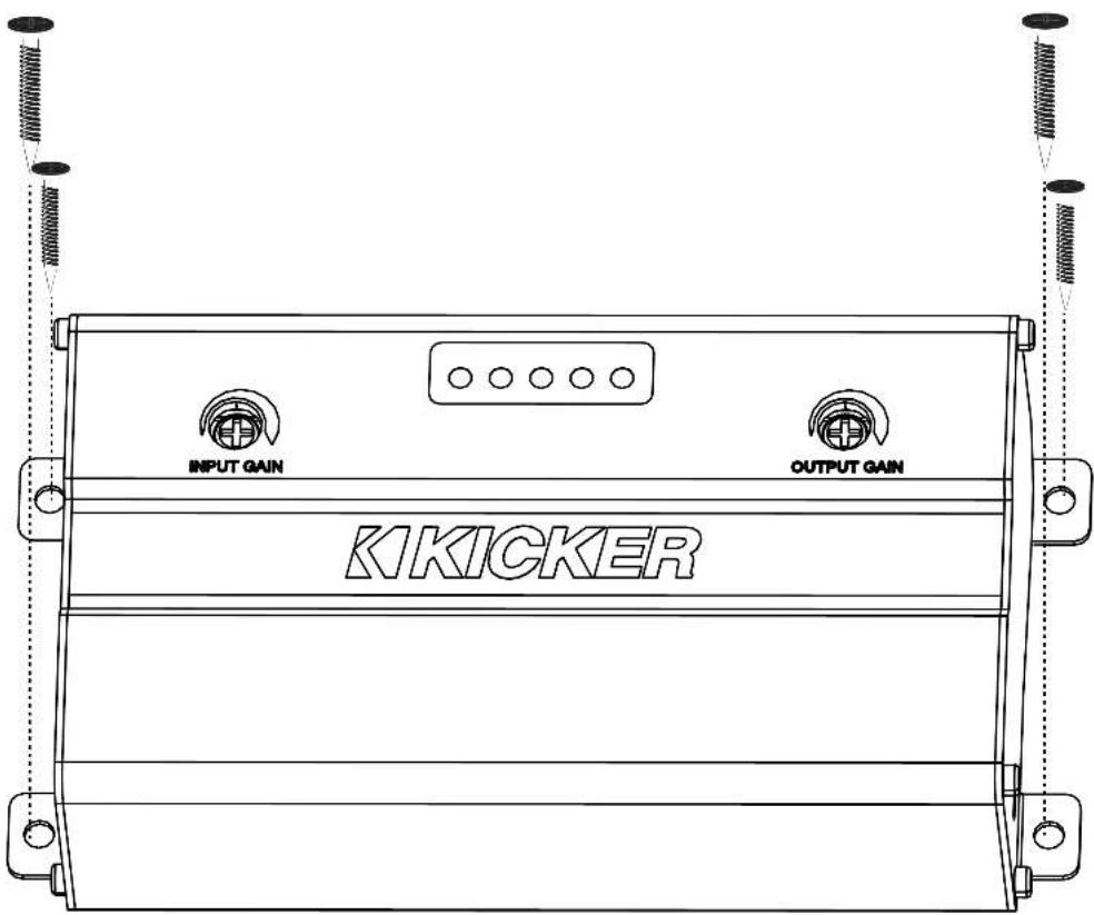
Choose a structurally sound location to mount the KEYLOC. Make sure there are no items behind the area where the screws will be driven. If possible, mount the KEYLOC behind the dash or in the climate-controlled passenger compartment. Drill four holes using a 7/64" (3mm) bit and use the supplied #8 screws to mount.
Wiring
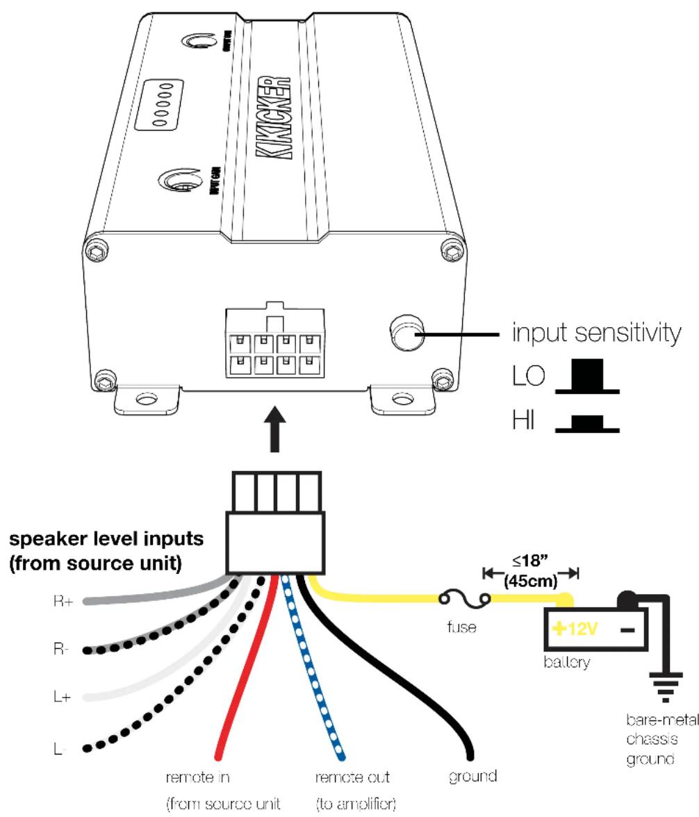
Disconnect the vehicle's battery to avoid an electrical short. Then connect the ground wire to the KEYLOC. Make the ground wire short, 24" (60cm) or less, and connect it to a paint-and-corrosion-free, solid, metal area of the vehicle's chassis. Keep the audio signal cable away from factory wiring harnesses and other power wiring. If you need to cross this wiring, cross it at a 90 degree angle. Connect your source units speaker outputs to the KEYLOC speaker inputs. When interfacing into factory speaker wires it is recommended to splice and solder, If you need to use wire taps make sure you use proper sized wire taps to ensure a solid connection.
If your head unit has a remote output you can connect this to the remote input of the KEYLOC. If your head unit does not have a remote output, the KEYLOC can use the DC offset that is present on the speaker outputs of most factory head units. To measure for DC offset, connect your multimeter's negative lead to the vehicle's chassis ground, the positive lead to the speaker wire you are interfacing with, and set the multimeter to 'DC volts'. When the source unit you're using is on, you should see DC voltage from between 2.5V–6V. The KEYLOC will sense this DC offset to turn on, and output 12V on its own remote output (up to 100mA) to turn on your aftermarket amplifier(s).
Test the output voltage of the audio source before selecting the input level setting. In general, if your input signal is coming from the source unit, use the LO Level Input Sensitivity setting. If your input signal is coming from a factory amplifier, use the HI Level Input Sensitivity setting. The LO range can accept
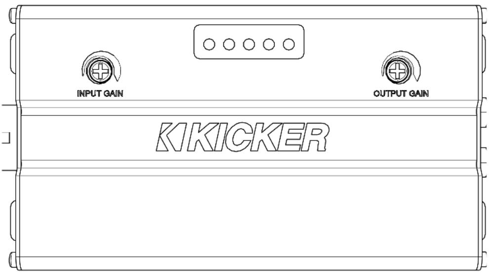
125mV-10V. The HI range can accept 1V – 40 V. The KEYLOC can output up to 10V of preamp RCA level output, adjustable with the Output Gain knob.
In the LO range, there is a 60Ω load for use with newer smart radios that shut off their outputs if they do not detect a speaker. If there is a need to load a source unit that has an output voltage greater than 10V, please use the KISLOAD products instead of the KEYLOC's built in load resistors.
Install a 2A fuse between the KEYLOC and battery. The fuse should be within 18" (45cm) of the power source and in-line with the harness' yellow power cable, which is connected to the KEYLOC. Connect the preamp-level RCA outputs to your amplifier.
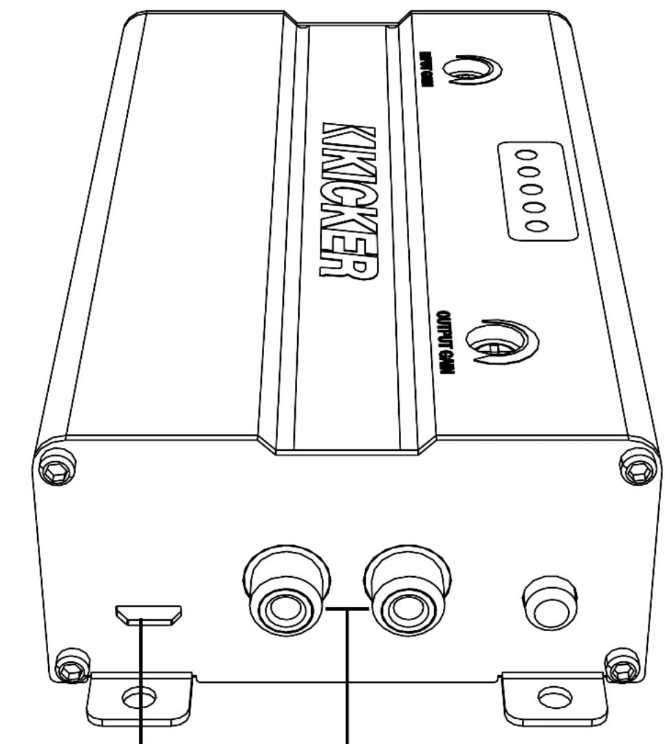
USB for internal use only
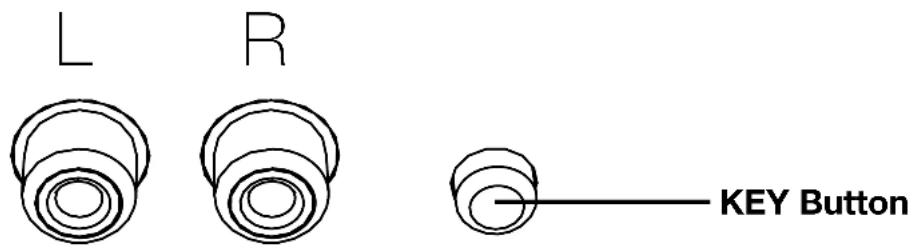
RCA Outputs (to amplifier)
The KEYLOC is a 2-channel DSP based active line output converter with the following features.
Automatic Turn-on: DC offset remote input turn-on, and remote output turn-on (100mA) to turn on other products.
Frequency Response Correction: Smooths frequency response of two channels from your source unit via EQ correction. It can fix EQs with Qs ranging from 0.5-10 with up to +/- of 12dB of boost or cut.
Factory Time Delay Defeat: Ranging from .06mS – 10mS, the algorithm is accurate down to .06mS.
ALL-Pass Filter Defeat: The KEYLOC can correct up to three all-pass filters on one channel. The All-pass filters can have a Q ranging from 0.5–3.5, as long as they do not interact with the other All-Pass filter's phase.
Passive Frequency Detection: Before running the KEYLOC setup process, it is in passive frequency detection mode. You can use this mode to detect what band of frequencies are available on the given speaker outputs that the KEYLOC is connected to.
Signal Identification
The KEYLOC will help you identify the correct OEM wires to which you should connect using the following steps:
- Turn the Input Gain on the KEYLOC all the way down.
- Turn the audio source up to at least 1/2 volume.
- Play the Pink Noise track from
https://www.kicker.com/test-tones - Turn the Input Gain up slowly until Low, Mid, and High LEDs begin to light up.
The Low, Mid, and High LEDs will turn on to indicate the frequency range that has been detected. They will alternately blink for left and right channels every half second. If both channels are the same, the LED(s) will be solid. The LED that lights up first will be the best application for the signal you are currently receiving. The more gain you must add to light up the remaining LEDs, the less signal is available for those applications.
Status LEDs
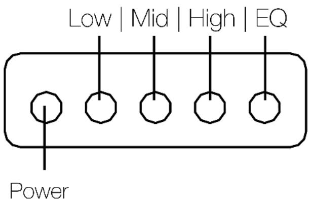
Frequency Detection
Low
20Hz-200Hz
Mid
200Hz-2kHz
High
2kHz-20kHz
Signal Restoration
Once the KEYLOC has been wired and mounted, you're ready to analyze and repair the signal from your source unit. Visit https://www.kicker.com/test-tones and download the GainMatchSweep, Noisefloor and FullTest test tracks, using the appropriate file type for your signal source. These are custom audio files that, when played from your source unit to the KEYLOC, will allow the KEYLOC to determine what frequency, coloration, and staging corrections to make.
During the key process if you accidentally push the KEY button before playing the Noise floor track, the KEYLOC will have an error and all LEDs will flash. You must then press the KEY button to exit the KEY process. You will need to re-enter the KEY process to start again if you do this.
Automatic Setup:
- Verify the input gain of the KEYLOC is turned all the way down. Set the Source unit to 3/4 volume or right before it starts to clip.
- Press and hold the KEY Button for 8 seconds. You will see the LEDs sweep from 1 – 4 and then 4 – 1.
Release the KEY Button and LED 1 will light up, LEDs 2 – 4 will be off. - Play track: GainMatchSweep from the source unit.
- Turn the KEYLOC input gain knob up, watching LEDs 3 and 4, until either starts to blink.
- Turn the KEYLOC input gain knob down until both LEDs stop blinking. Wait for 10 seconds to verify the
LEDS have stopped blinking.
- Stop track: GainMatchSweep, then play track: Noise floor
- Press the KEY Button. LED 1 will begin to blink. When the Noise floor is detected, LED1 will stop blinking and LED2 will start blinking.
- Play track: FullTest. While the track is running you will see the LEDs progress from LED1 to LED4. The FullTest track is 22 minutes long, however most corrections will only take between three to eight minutes.
- The LEDs will begin to flash once the KEYLOC has collected enough data and is processing the test results.
- The LEDs will sweep back and forth when the algorithm has completed, and audio will begin passing. Press the KEY button to exit the set-up mode.
- LED 4 will turn on to indicate the EQ correction is running. LEDs 1 – 3 will light up to indicate the available frequency ranges.
To toggle the EQ correction ON/OFF, press the KEY button once. If LED4 is ON, EQ correction is on. If LED 4 is OFF, EQ correction is off.
To reset to factory: Enter the main menu by pressing and holding the KEY button for 6 seconds. You will see the LEDs sweep from 1 – 4. Release the KEY Button and LED 1 will light up. Click the KEY button until LED 3 is illuminated, then hold the KEY button until all LEDs are illuminated. Release the KEY button and the unit will restart. Your KEYLOC is now reset back to factory.
Error Codes:
If the power LED and any combination of LEDs begin to blink, it indicates an error in the setup process. press the KEY button to reset the device.
LEDs 1, 2, 3, 4 - ON
Unable to find the noise floor. This indicates there is too much signal, or it is too noisy. This usually happens when the Noise Floor track is not playing before beginning Step 7.
LEDs 2, 3, 4 - or 1, 3, 4 - ON
Unable to interpret frequency response. This usually indicates the input is clipping or it is too noisy.
Navigating the Menu:
After the Auto setup process has completed, you'll be able to navigate the KEYLOC menu using the KEY button and LEDs. To enter the menu, press and hold the KEY button for 4 seconds. You will see the LEDS sweep 1-4 - release the KEY button. Quick-press the KEY button to cycle through the menu options:
LED1 - Allpass or Time-Delay defeat ON/OFF
Solid: Time-Delay correction is active
Blinking: Time-delay/allpass defeated
Press and hold the KEY button for 2 seconds to toggle defeat ON/OFF
LED2 - Gain Match Status
LED 2 indicates Left/Right Channel gain matching status.
Solid: On
Blinking: Off
LED3 - Reset KEYLOC
Hold the KEY button for 10 seconds
LED4 - Exit the Menu
Hold the KEY button for 1 second to exit the menu
Line-Output Conversion
After Auto Setup is complete, use the Output Gain to match the output voltage of the KEYLOC to the input sensitivity voltage of your amplifier. If you're not using gain match capable electronics or a voltmeter/multimeter, listening for audible distortion is always the next best way to set your gain.
Sending a high voltage signal to your amplifier when possible is always the best practice. To set the Output Gain, turn the KEYLOC Output Gain and the input gain of your amplifier all the way down. With audio playing, turn the KEYLOC Output Gain up until you have achieved your desired volume level or you begin to hear distortion, then reduce the Output Gain until it's gone.
Troubleshooting
If the KEYLOC becomes frozen or stuck during algorithmic calculation, does not appear to be working, or gives an error code, check the obvious things first such as blown fuses, poor or incorrect wiring connections, incorrect setting of gain controls, etc.
Tips for SETUP:
-
If you have issues getting a smoothed EQ response on an Real-Time Analysis, go back and check the INPUT GAIN match of the KEYLOC. If there are tall peaking filters in your analysis, it can take two or three sweeps of the GAIN MATCH track to ensure you have gain-matched with your device (wait 10 – 15 seconds to make sure the gain match LEDs are not flashing). If you're still seeing an issue where the frequency response is not being smoothed, it is suggested to turn the input gain down \~1/4 of a turn and run the KEYLOC setup process again.
-
If the issue persists, it is very likely that you are clipping the outputs of your audio source. Use the GAIN SWEEP track and an oscilloscope to verify that the signal coming into the KEYLOC is not clipping. If it is turn down the volume on the source unit.
-
In most systems, you will not be using a fully active DSP after the KEYLOC. In these cases, you would likely want to turn off the All pass/Time delay defeat for the best stereo imaging. See page 13.
-
To keep the noise floor (hiss) low, we have designed the KEYLOC to not add more than 18db of gain to any one frequency. In most applications, this should return the frequency response you back to a linear response of +/- 1.5dB in the frequency bandwidth you are using.
-
During the key process if you accidentally push the KEY button before playing the NOISE FLOOR track, the KEYLOC will have an error and all LEDs will flash. You must then press the KEY button to exit the KEY process. You will need to re-enter the KEY process to start again.
No power? With a Volt Ohm Meter (VOM) check the following: ①+12 volt power terminal (should read +12V to +16V) ② Remote turn-on terminal (should read +12V to +16V) ③ Check for reversed power and ground connections ④ Ground terminal, for proper conductivity.
Power on, no signal? Check the following: ① RCA connections ② Test audio source signal, either with a "known good" output device or other means.
No or low output? ① Check the balance and fader controls on source unit. ② Check the RCA (or speaker input) and speaker output connections. ③ Check the volume level on your source unit, to include the volume level of any connected phones or MP3 players.
KEYLOC frozen or stuck in operating procedure? ① Cycle the power
② Reset the remote ③ Reset the KEYLOC
Alternator noise-whining sound with engine's RPM? ①Check for damaged RCA (or speaker input) cable ②Check the routing of RCA (or speaker input) cable ③Check the source unit for proper grounding ④Check the gain settings and turn them down if they are set too high.
CAUTION: When jump starting the vehicle, be sure that connections made with jumper cables are correct. Improper connections can result in blown fuses as well as the failure of other critical systems in the vehicle.
If you have more questions about the installation or operation of your new KICKER product, see the Authorized KICKER Dealer where you made your purchase. For more advice on installation, click on the SUPPORT tab on the KICKER homepage, www.KICKER.com. Choose the TECHNICAL SUPPORT tab, choose the subject you are interested in, and then download or view the corresponding information. Please E-mail support@KICKER.com or call Technical Services (405) 624-8583 for unanswered or specific questions.
When purchased from an Authorized KICKER Dealer, KICKER warrants this product to be free from defects in material and workmanship under normal use for a period of TWO (2) YEARS from date of original purchase with receipt. If this product is identified as "Refurbished" or "B Goods", the warranty is limited to a period of THREE (3) MONTHS from the date of original purchase. In all cases you must have the original receipt. Should service be necessary under this warranty for any reason due to manufacturing defect or malfunction during the warranty period, KICKER will repair or replace (at its discretion) the defective merchandise with equivalent merchandise. Warranty replacements may have cosmetic scratches and blemishes. Discontinued products may be replaced with more current equivalent products. This warranty is valid only for the original purchaser and is not extended to owners of the product subsequent to the original purchaser. Any applicable implied warranties are limited in duration to a period of the express warranty as provided herein beginning with the date of the original purchase at retail, and no warranties, whether express or implied, shall apply to this product thereafter. Some states do not allow limitations on implied warranties; therefore, these exclusions may not apply to you. This warranty gives you specific legal rights; however you may have other rights that vary from state to state.
WHAT TO DO IF YOU NEED WARRANTY OR SERVICE:
Defective merchandise should be returned to your local Authorized Stillwater Designs (KICKER) Dealer for warranty service. Assistance in locating an Authorized Dealer can be found at www.KICKER.com or by contacting Stillwater Designs directly. You can confirm that a dealer is authorized by asking to see a current authorized dealer window decal.
If it becomes necessary for you to return defective merchandise directly to Stillwater Designs (KICKER), call the KICKER Customer Service Department at (405) 624-8510 for a Return Merchandise Authorization (RMA) number. Package only the defective items in a package that will prevent shipping damage, and return to:
Stillwater Designs, 3100 North Husband St, Stillwater, OK 74075
The RMA number must be clearly marked on the outside of the package. Please return only defective components. The return of functioning items increases your return freight charges. Non-defective items will be returned freightcollect to you. For example, if a subwoofer is defective, only return the defective subwoofer, not the entire enclosure. Include a copy of the original receipt with the purchase date clearly visible, and a “proof-of-purchase” statement listing the Customer’s name, Dealer’s name and invoice number, and product purchased. Warranty expiration on items without proof-of-purchase will be determined from the type of sale and manufacturing date code. Freight must be prepaid; items sent freight-collect, or COD, will be refused.
WHAT IS NOT COVERED?
This warranty is valid only if the product is used for the purpose for which it was designed. It does not cover:
o Damage due to improper installation
o Subsequent damage to other components
o Damage caused by exposure to moisture, excessive heat, chemical cleaners, and/or UV radiation
o Damage through negligence, misuse, accident or abuse. Repeated returns for the same damage may be considered abuse
o Any cost or expense related to the removal or reinstallation of product
o Speakers damaged due to amplifier clipping or distortion
o Items previously repaired or modified by any unauthorized repair facility
o Return shipping on non-defective items
o Products with tampered or missing barcode labels
o Products with tampered or missing serial numbers
o Products returned without a Return Merchandise Authorization (RMA) number
o Products purchased from an UNAUTHORIZED dealer
o Freight Damage
o The cost of shipping product to KICKER
o Service performed by anyone other than KICKER
HOW LONG WILL IT TAKE?
KICKER strives to maintain a goal of one week turnaround for all electronics (amplifiers, crossovers, equalizers, etc.) returns. Delays may be incurred if lack of replacement inventory or parts is encountered. Failure to follow these steps may void your warranty. Any questions can be directed to the KICKER Customer Service Department at (405) 624-8510. Contact your International KICKER dealer or distributor concerning specific procedures for your country's warranty policies.
KICKER® KEYLOC™
Customer Information Card | Tarjeta de Información | Carte Info | Infokarte
KICKER
keycscb20
Beer Music Enthusiest,
Thank you and congruities on your purchase of the KICKH-K-Y! GO! This DSP powered Line Co Converter promises to
revolutionize the audio installation process in your vehicle. Using state of the art algorithm, to analyze the output of your factory source.
unl, you can tell the EQ curve of your
audio signal, restore lost bases, defeat sil-pass filters or factory time delay, and identify
available frequency ranges. This provides you with a clean, flat sign for use with KICKER amplifiers and signal processors, giving you
the power to shape your music in any form of fashion on you desire.
Scoorely
Steve Iroy President/CEO
Steve Rby Presidents/OFO
Chère/Cher audopole
Steve By President/CEO
Scan here for
owner's manual
Escanee aquí para
The KEYLOC can help you identify the correct OEM wires to which you should connect. Wire the KEYLOC as shown, then use the following steps:
-
Turn the Input Gain on the KEYLOC all the way down. 2. Turn the audio source up to at least 1/2 volume.
-
Play the Pink Noise track. 4. Turn the Input Gain up slowly until Low, Mid, and High LEDs begin to light up.
The LED that lights up first will be the best application for the signal you are currently receiving. The more gain you must add to light up the remaining LEDs, the less signal is available for those applications.
Remote In Remote Out Ground
Operation: Once the KEYLOC has been wired and mounted, it's time to analyze and repair the signal from your source unit. Visit https://www.kicker.com/test-tones-and-download the appropriate file type for your signal source GainMatchSweep, Noisefloor and FullTest test tracks. These are custom audio files that, when played from your source unit to the KEYLOC, will allow the KEYLOC to determine what frequency, coloration, and staging corrections to make.
- Verify the input gain of the KEYLOC is turned all the way down. Set the Source unit to 3/4 volume or right before it starts to clip.
- Press and hold the KEY Button for 8 seconds. You will see the LEDs sweep from 1 - 4 and then 4 - 1. Release the KEY Button and LED 1 will light up, LEDs 2 - 4 will be off.
- Play track: GainMatchSweep from the source unit.
- Turn the KEYLOC input gain knob up, watching LEDs 3 and 4, until either starts to blink.
- Turn the KEYLOC input gain knob down until both LEDs stop blinking. Wait for 10 seconds to verify the LEDs have stopped blinking.
- Stop track: GainMatchSweep, then play track: Noise floor
- Press the KEY Button. LED 1 will begin to blink. When the Noise floor is detected, LED1 will stop blinking and LED2 will start blinking.
- Play track: FullTest. While the track is running you will see the LEDs progress from LED1 to LED4. The FullTest track is 22 minutes long, however most corrections will only take between three to eight minutes.
- The LEDs will begin to flash once the KEYLOC has collected enough data and is processing the test results.
- The LEDs will sweep back and forth when the algorithm has completed, and audio will begin passing. Press the KEY button to exit the set-up mode.
- LED 4 will turn on to indicate the EQ correction is running. LEDs 1 – 3 will light up to indicate the available frequency ranges.
To toggle the EQ correction ON/OFF, press the KEY button once. If LED4 is ON, EQ correction is on. If LED 4 is OFF, EQ correction is off.
To reset to factory: Enter the main menu by pressing and holding the KEY button for 6 seconds. You will see the LEDs sweep from 1 - 4. Release the KEY Button and LED 1 will light up. Click the KEY button until LED 3 is illuminated, then hold the KEY button until all LEDs are illuminated. Release the KEY button and the unit will restart. Your KEYLOC is now reset back to factory.
- IMPORTANT SAFETY WARNING
- Specifications
- Model: KEYLOC
- Mounting
- Wiring
- Signal Identification
- Frequency Detection
- Low
- Mid
- High
- Signal Restoration
- Automatic Setup:
- Error Codes:
- LEDs 1, 2, 3, 4 - ON
- LEDs 2, 3, 4 - or 1, 3, 4 - ON
- Navigating the Menu:
- LED1 - Allpass or Time-Delay defeat ON/OFF
- LED2 - Gain Match Status
- LED3 - Reset KEYLOC
- LED4 - Exit the Menu
- Line-Output Conversion
- Troubleshooting
- Tips for SETUP:
- WHAT TO DO IF YOU NEED WARRANTY OR SERVICE:
- WHAT IS NOT COVERED?
- HOW LONG WILL IT TAKE?
- KICKER® KEYLOC™
- Customer Information Card | Tarjeta de Información | Carte Info | Infokarte
- KICKER
Brand : KICKER
Model : Keyloc
Category : Audio/video converter