
Vigor 3910 - Firewall Draytek - Free user manual and instructions
Find the device manual for free Vigor 3910 Draytek in PDF.


| Product Type | Multi-WAN Security Router (Firewall) |
| Model | Vigor 3910 |
| WAN Interfaces | 2 x SFP+ (10G/1G), 2 x 2.5GBase-T (2.5G/1G/100M/10M), 4 x GbE (1G/100M/10M) – configurable as WAN or LAN (P5-P8) |
| LAN Interfaces | 4 x GbE (P9-P12) fixed LAN, plus up to 8 configurable WAN/LAN ports |
| USB Ports | 2 x USB 2.0 |
| Console Port | 1 x RJ45 console |
| VPN Tunnels | Up to 100 concurrent tunnels; supports IPSec, PPTP, L2TP, L2TP over IPSec, OpenVPN, WireGuard, SSL VPN |
| VPN Performance | Hardware-based VPN acceleration with AES/DES/3DES encryption |
| Firewall Features | SPI (Stateful Packet Inspection), DoS/DDoS defense, spoofing defense, URL/content filtering, IM/P2P blocking |
| Content Security Management (CSM) | App enforcement, URL content filter, web content filter, DNS filter |
| Bandwidth Management | Session limits, bandwidth limits, QoS, application QoS |
| User Management | User-based authentication (Web, Alert Tool, Telnet), quotas (time/data), landing page, hotspot web portal |
| Routing | Static route, policy-based load balancing, OSPF, BGP, fast routing |
| High Availability | Active/standby HA with config sync |
| Central Management | Management of DrayTek APs and switches via built-in controller |
| Management Interfaces | Web UI (HTTP/HTTPS), Telnet, SNMP, TR-069, SSH |
| Operating Temperature | +5°C to +40°C |
| Humidity | Not specified (typical 10-90% non-condensing) |
| Power Supply | Internal power supply, 100-240V AC (typical), power consumption not specified |
| Form Factor | 1U rack-mountable (brackets included) or desktop with rubber feet |
| Warranty | 2 years from date of purchase |
Frequently Asked Questions - Vigor 3910 Draytek
User questions about Vigor 3910 Draytek
0 question about this device. Answer the ones you know or ask your own.
Ask a new question about this device
Download the instructions for your Firewall in PDF format for free! Find your manual Vigor 3910 - Draytek and take your electronic device back in hand. On this page are published all the documents necessary for the use of your device. Vigor 3910 by Draytek.
USER MANUAL Vigor 3910 Draytek
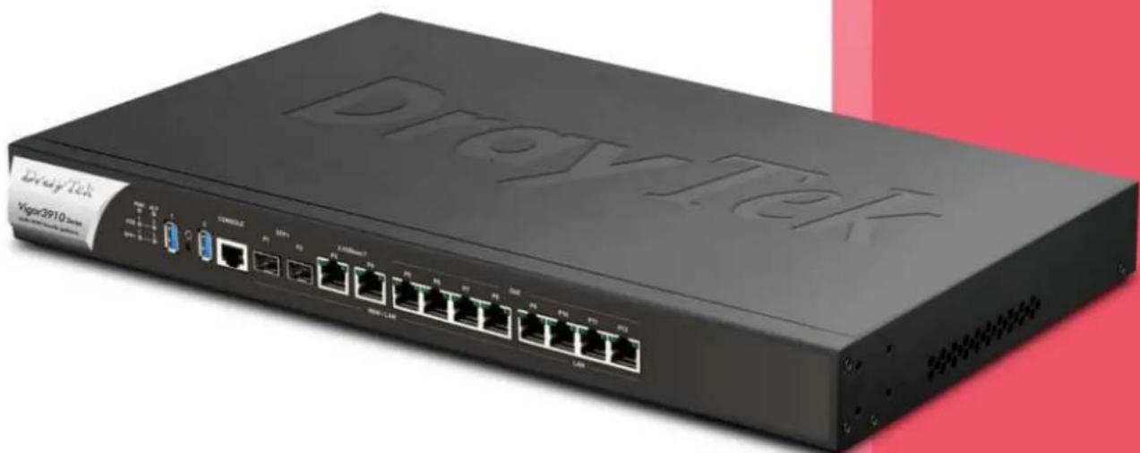
Multi-WAN Security Router
natural_image
Exterior view of a black ProxyTek network switch with multiple Ethernet ports and I/O ports (no readable text or symbols beyond branding)USER'S GUIDE
Vigor3910 Series Multi-WAN Security Router
User's Guide
Version: 1.61
Firmware Version: V4.3.2.5
(For future update, please visit DrayTek web site)
Date: January 29, 2024
Copyrights
© All rights reserved. This publication contains information that is protected by copyright. No part may be reproduced, transmitted, transcribed, stored in a retrieval system, or translated into any language without written permission from the copyright holders.
Trademarks
The following trademarks are used in this document:
● Microsoft is a registered trademark of Microsoft Corp.
● Windows 8, 10, 11 and Explorer are trademarks of Microsoft Corp.
● Apple and Mac OS are registered trademarks of Apple Inc.
● Other products may be trademarks or registered trademarks of their respective manufacturers.
Safety Instructions
- Read the installation guide thoroughly before you set up the router.
- The router is a complicated electronic unit that may be repaired only be authorized and qualified personnel. Do not try to open or repair the router yourself.
- Do not place the router in a damp or humid place, e.g. a bathroom.
● The router should be used in a sheltered area, within a temperature range of +5 to +40 Celsius. - Do not expose the router to direct sunlight or other heat sources. The housing and electronic components may be damaged by direct sunlight or heat sources.
- Do not deploy the cable for LAN connection outdoor to prevent electronic shock hazards.
- Do not power off the device when saving configurations or firmware upgrades. It may damage the data in a flash. Please disconnect the Internet connection on the device before powering it off when a TR-069/ ACS server manages the device.
- Keep the package out of reach of children.
- When you want to dispose of the router, please follow local regulations on conservation of the environment.
Warranty
We warrant to the original end user (purchaser) that the router will be free from any defects in workmanship or materials for a period of two (2) years from the date of purchase from the dealer. Please keep your purchase receipt in a safe place as it serves as proof of date of purchase. During the warranty period, and upon proof of purchase, should the product have indications of failure due to faulty workmanship and/or materials, we will, at our discretion, repair or replace the defective products or components, without charge for either parts or labor, to whatever extent we deem necessary tore-store the product to proper operating condition. Any replacement will consist of a new or re-manufactured functionally equivalent product of equal value, and will be offered solely at our discretion. This warranty will not apply if the product is modified, misused, tampered with, damaged by an act of God, or subjected to abnormal working conditions. The warranty does not cover the bundled or licensed software of other vendors. Defects which do not significantly affect the usability of the product will not be covered by the warranty. We reserve the right to revise the manual and online documentation and to make changes from time to time in the contents hereof without obligation to notify any person of such revision or changes.
Table of Contents
Part I Installation....1
I-1 Introduction ...... 2
I-1-1 Indicators and Connectors .... 3
I-2 Hardware Installation 5
I-2-1 Installing Vigor Router 5
I-2-2 Rack-Mounted Installation....6
I-3 Accessing Web Page 7
I-4 Changing Password....9
I-5 Dashboard.... 10
I-5-1 Virtual Panel 11
I-5-2 Quick Access for Common Used Menu 12
I-5-3 GUI Map 13
I-5-4 Web Console 14
I-5-5 Config Backup 14
I-5-6 Manual Download.... 15
I-5-7 Logout.... 15
I-5-8 Online Status.... 16
I-5-8-1 Physical Connection....16
I-5-8-2 Virtual WAN 18
I-6 Quick Start Wizard 19
I-6-1 For WAN1 (Fiber) 20
I-6-2 For WAN3 (Ethernet - 2.5G)....27
I-6-3 For WAN5\~WAN8 (Etherent) 34
I-7 Service Activation Wizard 41
I-8 Registering Vigor Router.... 43
I-9 VPN Client Wizard 46
I-10 VPN Server Wizard 53
Part II Connectivity ....63
II-1 Port Setup 64
II-2 WAN 65
Web User Interface 66
II-2-1 General Setup 66
II-2-2 Internet Access....71
II-2-2-1 Details Page for PPPoE....73
II-2-2-2 Details Page for Static or Dynamic IP....76
II-2-2-3 Details Page for IPv6 - Offline in Ethernet WAN....80
II-2-2-4 Details Page for IPv6 - PPP 80
II-2-2-5 Details Page for IPv6 - TSPC....81
II-2-2-6 Details Page for IPv6 - AICCU 83
II-2-2-7 Details Page for IPv6 - DHCPv6 Client 85
II-2-2-8 Details Page for IPv6 - Static IPv6....86
II-2-2-9 Details Page for IPv6 - 6in4 Static Tunnel 87
II-2-2-10 Details Page for IPv6 - 6rd 90
II-2-3 Multi-VLAN 92
II-2-4 WAN Budget....96
II-2-4-1 General Setup 96
II-2-4-2 Status 99
II-3 LAN 100
Web User Interface....102
II-3-1 General Setup 102
II-3-1-1 Details Page for LAN1 - Ethernet TCP/IP and DHCP Setup.... 103
II-3-1-2 Details Page for IP Routed Subnet 106
II-3-1-3 Details Page for LAN1 - IPv6 Setup.... 108
II-3-1-4 DHCP Server Option 112
II-3-2 VLAN 113
II-3-3 Bind IP to MAC 115
II-3-4 Port Mirror/Packet Capture.... 118
II-3-5 Wired 802.1x 120
II-3-6 PPPoE Server 122
II-4 NAT 123
Web User Interface 124
II-4-1 Port Redirection.... 124
II-4-2 DMZ Host 128
II-4-3 Open Ports 131
II-4-4 Port Triggering.... 133
II-4-5 Fast NAT 137
II-4-6 ALG....138
II-5 Applications 139
Web User Interface 141
II-5-1 Dynamic DNS 141
II-5-2 LAN DNS / DNS Forwarding 146
II-5-3 DNS Security 150
II-5-3-1 General Setup 150
II-5-3-2 Domain Diagnose.... 151
II-5-4 Schedule....152
II-5-5 RADIUS/TACACS+ 155
II-5-5-1 External RADIUS.... 155
II-5-5-2 Internal RADIUS 157
II-5-5-3 External TACACS+.... 160
II-5-6 Active Directory/ LDAP 161
II-5-6-1 General Setup 161
II-5-6-2 Active Directory / LDAP Profiles 162
II-5-7 UPnP 163
II-5-8 IGMP....165
II-5-8-1 General Setting 165
II-5-8-2 Working Status 166
II-5-9 Wake on LAN 167
II-5-10 SMS / Mail Alert Service.... 168
II-5-10-1 SMS Alert 168
II-5-10-2 Mail Alert 169
II-5-11 Bonjour 170
II-5-12 High Availability 173
II-5-12-1 General Setup.... 173
II-5-12-2 Config Sync 175
II-5-13 Local 802.1X General Setup 177
II-5-14 Smart Action 179
Application Notes 181
A-1 How to Implement the LDAP/AD Authentication for User Management? ..... 181
A-2 How to use DrayDDNS? 184
II-6 Routing....189
Web User Interface 190
II-6-1 Static Route 190
II-6-2 Load-Balance /Route Policy 195
II-6-2-1 General Setup 195
II-6-2-2 Diagnose for Route Policy 201
II-6-3 Fast Routing 205
II-6-4 OSPF 206
II-6-5 BGP 208
II-6-4-1 Basic Settings.... 209
II-6-4-2 Static Network 210
Application Notes 211
A-1 How to Customize a Secure Route between VPN Router and Remote Router by Using
Route Policy 211
Part III VPN 215
III-1 VPN and Remote Access.... 216
Web User Interface 216
III-1-1 Remote Access Control.... 217
III-1-1-1 Remote Access Control Setup 217
III-1-2 Bind to WAN 218
III-1-2 PPP General Setup 219
III-1-3 SSL General Setup....221
III-1-4 IPsec General Setup 222
III-1-5 IPsec Peer Identity 225
III-1-6 VPN Matcher Setup.... 227
III-1-7 OpenVPN 229
III-1-7-1 OpenVPN Server Setup 229
III-1-7-2 Client Config.... 232
III-1-7-3 Import Certificate 233
III-1-8 WireGuard 234
III-1-9 Remote Dial-in User 235
III-1-10 LAN to LAN....242
III-1-11 VPN Trunk Management 252
III-1-12 Connection Management 257
Application Notes 259
A-1 How to Build a LAN-to-LAN VPN Between Remote Office and Headquarter via IPsec Tunnel (Main Mode).... 259
III-2 Certificate Management.... 264
Web User Interface 265
III-2-1 Local Certificate 265
III-2-2 Trusted CA Certificate 270
III-2-3 Certificate Backup 273
III-2-4 Self-Signed Certificate.... 274
Part IV Security 275
IV-1 Firewall....276
Web User Interface 278
IV-1-1 General Setup 278
IV-1-2 Filter Setup.... 283
IV-1-3 Defense Setup 293
IV-1-3-1 DoS Defense 293
IV-1-3-2 Spoofing Defense.... 296
IV-1-4 Diagnose 296
Application Notes 299
A-1 How to Configure Certain Computers Accessing to Internet 299
IV-2 CSM (Central Security Management).... 302
Web User Interface 303
IV-2-1 APP Enforcement Profile 303
IV-2-2 URL Content Filter Profile 305
IV-2-3 Web Content Filter Profile.... 309
IV-2-4 DNS Filter Profile 312
Application Notes 314
A-1 How to Create an Account for MyVigor 314
A-2 How to Block Facebook Service Accessed by the Users via Web Content Filter / URL Content Filter 318
A-3 How to use APP Enforcement to block application like Facebook, YouTube or TeamViewer? 323
Part V Management ....327
V-1 System Maintenance 328
Web User Interface 329
V-1-1 System Status 329
V-1-2 TR-069 331
V-1-2-1 ACS and CPE Settings.... 331
V-1-2-2 Reporting Configuration.... 333
V-1-2-3 Export Parameters.... 335
V-1-3 Administrator Password 336
V-1-4 User Password.... 339
V-1-5 Login Page Greeting 342
V-1-6 Configuration Backup.... 344
V-1-7 Configuration Export 346
V-1-8 Webhook 347
V-1-9 Syslog/Mail Alert 348
V-1-10 Time and Date.... 351
V-1-11 SNMP 352
V-1-12 Management 354
V-1-13 Self-Signed Certificate 359
V-1-14 Reboot System.... 361
V-1-15 Firmware Upgrade 362
V-1-16 Internal Service User List 363
V-1-17 Dashboard Control 364
V-1-18 Max Connection 364
V-2 Bandwidth Management 365
Web User Interface 366
V-2-1 Sessions Limit 366
V-2-2 Bandwidth Limit 368
V-2-3 Quality of Service 370
V-2-4 APP QoS 376
V-3 User Management 377
Web User Interface 378
V-3-1 General Setup 378
V-3-2 User Profile 380
V-3-3 User Group.... 385
V-3-4 User Online Status 386
V-3-5 PPPoE User Online Status 387
Application Notes 388
A-1 How to authenticate clients via User Management 388
A-2 How to use Landing Page Feature 397
V-4 Hotspot Web Portal 401
Web User Interface 401
V-4-1 Profile Setup.... 401
V-4-1-1 Login Method 402
V-4-1-2 Steps for Configuring a Web Portal Profile.... 403
V-4-2 Users Information.... 419
V-4-2-1 User Info 419
V-4-2-2 Database Setup.... 421
V-4-3 Quota Management 423
V-4-4 PIN Generator 426
V-4-4-1 PIN Status 426
V-4-4-2 PIN Generator 427
V-4-4-3 PIN Voucher 428
Application Notes 430
A-1 How to allow users login to Vigor's Hotspot with their social media accounts (e.g.,
Facebook & Google) 430
A-2 How to allow hotspot clients to get login PIN code via SMS?...... 438
V-5 Central Management (AP) 446
Web User Interface 447
V-5-1 Dashboard.... 447
V-5-2 Status 448
V-5-3 WLAN Profile.... 449
V-5-4 AP Maintenance.... 454
V-5-5 Traffic Graph 455
V-5-6 Event Log 456
V-5-7 Total Traffic 457
V-5-8 Station Number 457
V-5-9 Load Balance 458
V-6 Central Management (Switch) 460
Web User Interface 461
V-6-1 Status 461
V-6-1-1 Switch Status 461
V-6-1-2 Switch Hierarchy 463
V-6-1-3 Detailed Info.... 464
V-6-1-4 TR069 Setting.... 465
V-6-2 Profile 466
V-6-3 Group 469
V-6-4 Maintenance.... 471
V-6-5 Alert and Log....472
V-6-5-1 Alert Setup.... 472
V-6-5-2 Switch and Port Setup 473
V-6-6 Database Setup 475
V-6-7 Support List 476
V-7 Central Management (External Devices).... 477
Part VI Others....479
VI-1 Objects Settings.... 480
Web User Interface 481
VI-1-1 IP Object 481
VI-1-2 IP Group....484
VI-1-3 IPv6 Object.... 485
VI-1-4 IPv6 Group 487
VI-1-5 Service Type Object....488
VI-1-6 Service Type Group 490
VI-1-7 Keyword Object.... 492
VI-1-8 Keyword Group 494
VI-1-9 File Extension Object 495
VI-1-10 SMS/Mail Service Object 497
VI-1-11 Notification Object....502
VI-1-12 String Object 504
VI-1-13 Country Object 505
VI-1-14 Objects Backup/Restore 507
Application Notes 508
A-1 How to Send a Notification to Specified Phone Number via SMS Service in WAN Disconnection 508
VI-2 USB Application 512
Web User Interface 513
VI-2-1 USB General Settings....513
VI-2-2 USB User Management 513
VI-2-3 File Explorer 515
VI-2-4 USB Device Status.... 517
VI-2-5 Temperature Sensor 519
Part VII Troubleshooting ....521
VII-1 Diagnostics 522
Web User Interface 523
VII-1-1 Dial-out Triggering....523
VII-1-2 Routing Table....524
VII-1-3 ARP Cache Table 525
VII-1-4 IPv6 Neighbour Table 526
VII-1-5 DHCP Table.... 527
VII-1-6 NAT Sessions Table 528
VII-1-7 DNS Cache Table 529
VII-1-8 Ping Diagnosis 530
VII-1-9 Data Flow Monitor 532
VII-1-10 Port Mirror/Packet Capture 534
VII-1-11 Traffic Graph 537
VII-1-12 VPN Graph....538
VII-1-13 Trace Route 540
VII-1-14 Syslog Explorer....541
VII-1-15 IPv6 TSPC Status 542
VII-1-16 High Availability Status 543
VII-1-17 Authentication Information 545
VII-1-18 DoS Flood Table 546
VII-1-19 Route Policy Diagnosis 547
VII-1-20 Debug Logs....549
VII-2 Checking If the Hardware Status Is OK or Not 550
VII-3 Checking If the Network Connection Settings on Your Computer Is OK or Not.... 551
VII-4 Pinging the Router from Your Computer 554
VII-5 Checking If the ISP Settings are OK or Not.... 556
VII-6 Backing to Factory Default Setting If Necessary 557
VII-7 Contacting DrayTek 559
Part VIII DrayTek Tools ....561
VIII-1 SmartVPN Client....562
VIII-1-1 DrayTek Android-based SmartVPN APP for the establishment of SSL VPN connection 562
VIII-1-2 How to Use SmartVPN Android APP to Establish SSL VPN Tunnel?...... 563
Part IX Telnet Commands....567
Accessing Telnet of Vigor3910 568
Part I Installation

This part will introduce Vigor router and guide to install the device in hardware and software.
I-1 Introduction
This is a generic International version of the user guide. Specification, compatibility and features vary by region. For specific user guides suitable for your region or product, please contact local distributor.
Vigor3910 Series, a broadband router, integrates IP layer QoS, NAT session/bandwidth management to help users control works well with large bandwidth.
By adopting hardware-based VPN platform and hardware encryption of AES/ DES/ 3DES, the router increases the performance of VPN greatly and offers several protocols (such as IPSec/ PPTP/ L2TP) with up to 100 VPN tunnels.
The object-based design used in SPI (Stateful Packet Inspection) firewall allows users to set firewall policy easily. CSM (Content Security Management) provides users control and management in IM (Instant Messenger) and P2P (Peer to Peer) more efficiency than before. By the way, DoS/ DDoS prevention and URL/ Web content filter strengthen the security outside and control inside.
Object-based firewall is flexible and allows your network be safe.
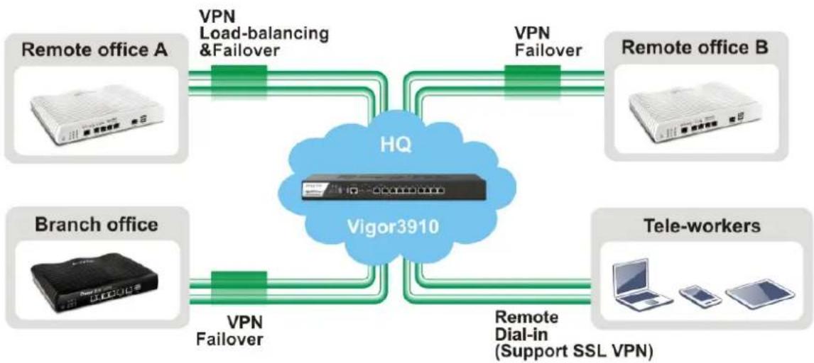
flowchart
graph TD
    A["Remote office A"] -->|VPN Load-balancing & Failover| B["HQ"]
    C["Remote office B"] -->|VPN Failover| B
    D["Branch office"] -->|VPN Failover| B
    E["Tele-workers"] -->|Remote Dial-in (Support SSL VPN)| B
    B --> F["Vigor3910"]
I-1-1 Indicators and Connectors
Before you use the Vigor router, please get acquainted with the LED indicators and connectors first.

| LED Status Explanation | ||
| PWR | On | The router is powered on. |
| Off | The router is powered off. | |
| ACT | Blinking | The system is active. |
| Off | The system is hanged. | |
| USB | On | The USB device is installed and ready. |
| Off | No USB device is installed. | |
| SFP+ | On | The fiber connection is established. |
| Blinking | The data is transmitting. | |
| Off | No fiber connection is established or the system is hanged. | |
| P3~P12 | On (Left) | The Ethernet link is established on corresponding port. |
| Off (Left) | No Ethernet link is established. | |
| Blinking (L) | The data is transmitting. | |
| On (Right) | The Ethernet link is established on corresponding port with 1G Mbps or above. | |
| Off (Right) | The Ethernet link is established on corresponding port with less than 1G Mbps. | |
| DMZ | LeftLED(Green) | On The port is connected. | |
| Off The port is disconnected. | |||
| Blinking The data is transmitting. | |||
| RightLED(Green) | On The port is connected with 1000Mbps. | ||
| Off The port is connected with 10/100Mbps. | |||
| LAN | LeftLED | On The port is connected. | |
| Off The port is disconnected. | |||
| Blinking The data is transmitting. | |||
| RightLED | On The port is connected with 1000Mbps. | ||
| Off The port is connected with 10/100Mbps | |||
| WAN1~WAN4 | LeftLED | On The port is connected. | |
| Off The port is disconnected. | |||
| Blinking The data is transmitting. | |||
| RightLED | On The port is connected with 1000Mbps. | ||
| Off The port is connected with 10/100Mbps | |||

| Interface Description | |
| USB1 / USB2 Connector for the USB device. | |
| Console Provided for technician use. | |
| SFP+(P1~P2) | Connector for SFP module with the rate of 10G/ 1G bps. |
| 2.5GBase-T(P3~P4) | Connector for remote network devices or local network devices (WAN/ LAN) with the rate of 2.5G/ 1G/ 100M/ 10M bps. |
| GbE P5~P8 Connectors for remote network devices or local network devices (WAN/ LAN) with the rate of 1G/ 100M/ 10M bps. | |
| GbE P9~P12 | Connector for local network devices (LAN) with the rate of 1G/ 100M/ 10M bps. |
 | The Factory Reset button is used to restore the default settings. Turn on the router (ACT LED is blinking). Press the hole and keep for more than 5 seconds. When you see the ACT LED begins to blink rapidly than usual, release the button. Then the router will restart with the factory default configuration. |
 | Connector for a power cord.ON/ OFF - Power switch. |
I-2 Hardware Installation
I-2-1 Installing Vigor Router
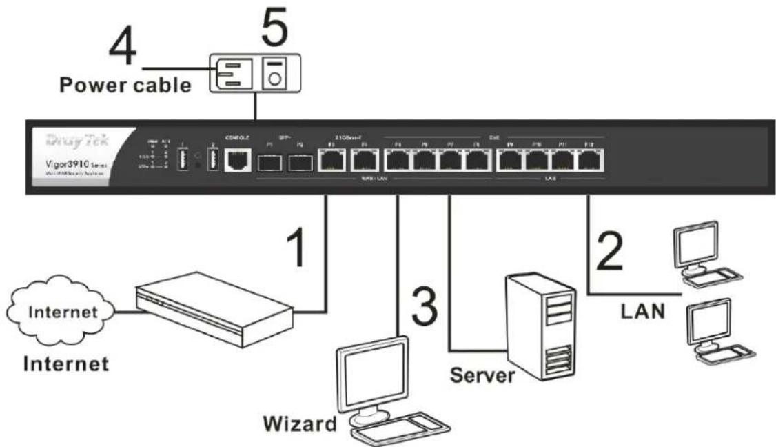
Before starting to configure the router, you have to connect your devices correctly.
- Connect a modem to any WAN port of Vigor3910 with Ethernet cable (RJ-45) to access Internet.
- Connect the other end of the cable (RJ-45) to the Ethernet port on your computer (that device also can connect to other computers to form a small area network). The LAN LED for that port on the front panel will light up.
- Connect a server/router (depends on your requirement) to any WAN port of Vigor3910 with Ethernet cable (RJ-45). The WAN LED will light up.
- Connect the power cord to Vigor3910's power port on the rear panel, and the other side into a wall outlet.
- Power on the device by pressing down the power switch on the rear panel. The PWR LED should be ON.
- The system starts to initiate. After completing the system test, the ACT LED will light up and start blinking.
Below shows an outline of the hardware installation for your reference.
flowchart
graph TD
    A["Power cable"] --> B["1"]
    B --> C["2"]
    C --> D["3"]
    D --> E["4"]
    E --> F["5"]
    G["Internet"] --> H["1"]
    I["Internet"] --> J["3"]
    K["Server"] --> L["2"]
    M["Computer"] --> N["LAN"]
    O["Wizard"] --> P["1"]
    Q["COM/CLZ"] --> R["1"]
    S["SPV"] --> T["1"]
    U["1100bit-F"] --> V["1"]
    W["16"] --> X["16"]
    Y["16"] --> Z["16"]
    AA["16"] --> AB["16"]
    AC["16"] --> AD["16"]
I-2-2 Rack-Mounted Installation
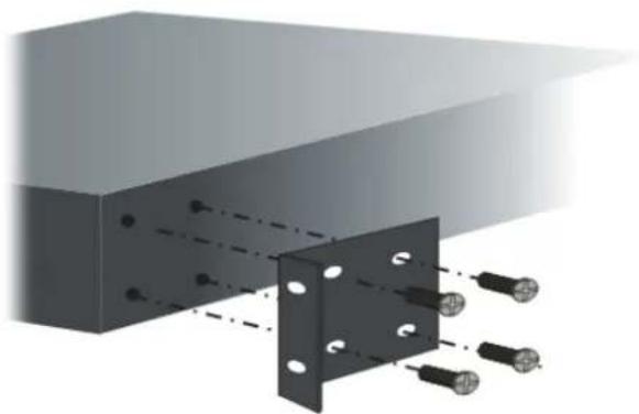
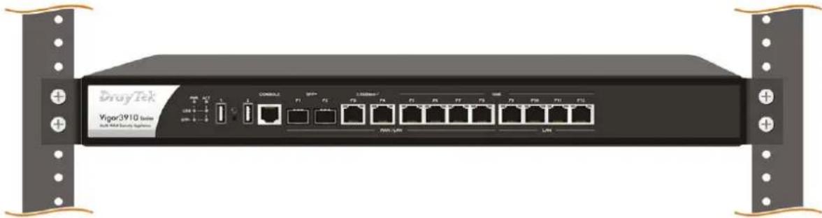
The Vigor3910 Series can be mounted on the wall by using standard brackets shown below.

Attach the brackets to the chassis of a rack. The second bracket attaches the other side of the chassis.
natural_image
3D diagram of a structural assembly with two black components and multiple bolts, no text or symbols presentAfter the bracket installation, the Vigor3910 Series chassis can be installed in a rack by using four screws for each side of the rack.
natural_image
Front view of a network switch device labeled 'Vigor3910 Series' with ports and connectors (no readable text beyond branding)Desktop Type Installation
Rubber pads are included with the Vigor3910 Series. These rubber pads improve the air circulation and decrease unnecessary rubbing on the desktop.
I-3 Accessing Web Page
- Make sure your PC connects to the router correctly.
You may either simply set up your computer to get IP dynamically from the router or set up the IP address of the computer to be the same subnet as the default IP address of Vigor router 192.168.1.1. For the detailed information, please refer to the later section - Trouble Shooting of the guide.
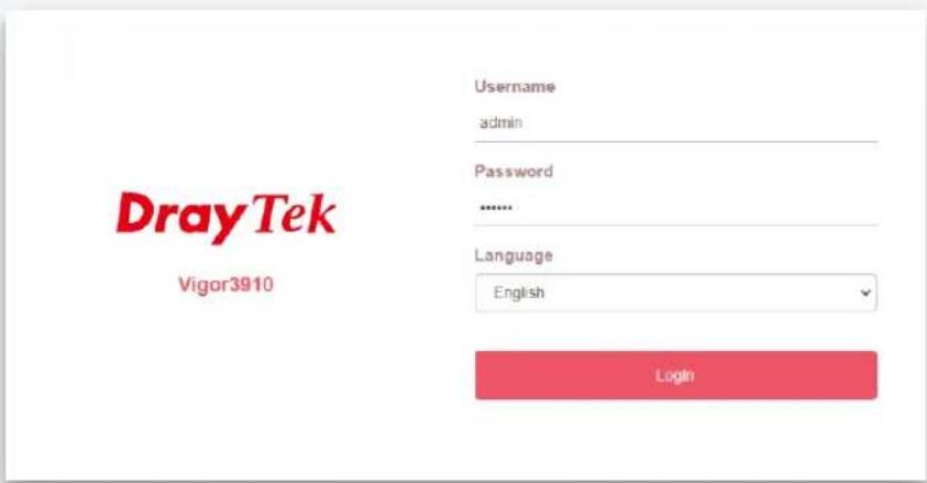
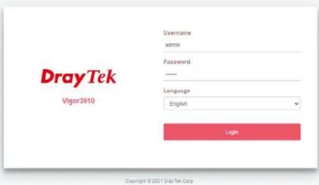
- Open a web browser on your PC and type http://192.168.1.1. The following window will be open to ask for username and password.
Copyright © 2021 DrayTek Corp
- Please type "admin/admin" as the Username/Password and click Login.

Info
If you fail to access to the web configuration, please go to "Trouble Shooting" for detecting and solving your problem.
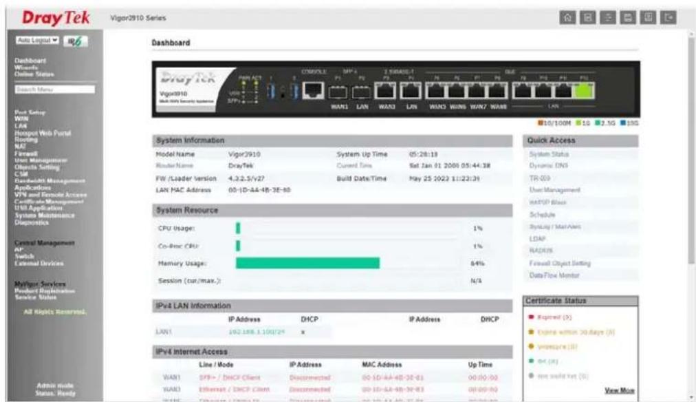
- Now, the Main Screen will appear.

Info
The home page will be different slightly in accordance with the type of the router you have.
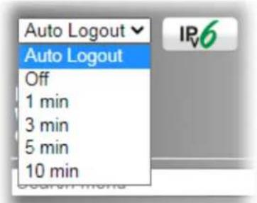
- The web page can be logged out according to the chosen condition. The default setting is Auto Logout, which means the web configuration system will logout after 5 minutes without any operation. Change the setting for your necessity.
I-4 Changing Password
Please change the password for the original security of the router.
-
Open a web browser on your PC and type http://192.168.1.1. A pop-up window will open to ask for username and password.
-
Please type "admin/admin" as Username/Password for accessing into the web user interface with admin mode.
-
Go to System Maintenance page and choose Administrator Password.
System Maintenance >> Administrator Password
Administrator Password
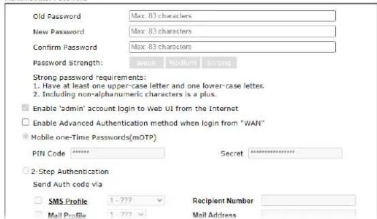
- Enter the login password (the default is "admin") on the field of Old Password. Type New Password and Confirm Password. Then click OK to continue.

Info
The maximum length of the password you can set is 23 characters.
- Now, the password has been changed. Next time, use the new password to access the Web user interface for this router.

Info
Even the password is changed, the Username for logging onto the web user interface is still "admin".
I-5 Dashboard
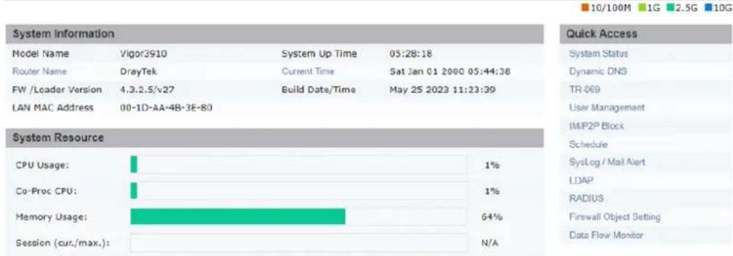
Dashboard shows the connection status including System Information, IPv4 Internet Access, IPv6 Internet Access, Interface (physical connection), Security and Quick Access.
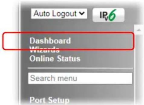
Click Dashboard from the main menu on the left side of the main page.
A web page with default selections will be displayed on the screen. Refer to the following figure:
Dashboard



I-5-1 Virtual Panel
On the top of the Dashboard, a virtual panel (simulating the physical panel of the router) displays the physical interface connection. It will be refreshed every five seconds. When you move and click the mouse cursor on LAN, or WAN, related web setting page will be open for you to configure if required.
Dashboard

| Port Color | Description | |
| LAN | Black LAN port is disconnected. | |
| Orange LAN port is connected at 10/100 Mbps. | ||
| Green LAN port is connected at 1 Gbps. | ||
| WAN | Black WAN port is disconnected. | |
| Orange WAN port is connected at 10/100 Mbps. | ||
| Green WAN port is connected at 1 Gbps. | ||
For detailed information about the LED display, refer to I-1-1 LED Indicators and Connectors.
I-5-2 Quick Access for Common Used Menu
All the menu items can be accessed and arranged orderly on the left side of the main page for your request. However, some important and common used menu items which can be accessed in a quick way just for convenience.
Look at the right side of the Dashboard. You will find a group of common used functions grouped under Quick Access.
The function links of System Status, Dynamic DDNS, TR-069, User Management, IM/ P2P Block, Schedule, Syslog/ Mail Alert, LDAP, RADIUS, Firewall Object Setting and Data Flow Monitor are displayed here. Move your mouse cursor on any one of the items and click on it. The corresponding setting page will be open immediately.
Dashboard
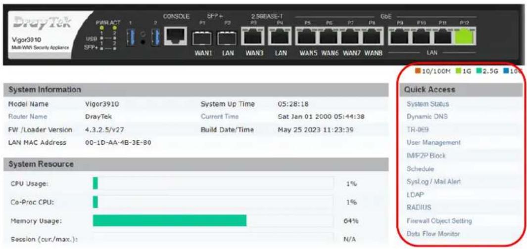
Besides, LAN, IP Routed Subnet, WAN interfaces, VPN security settings such as Remote Dial-in User and LAN to LAN also can be accessed on this page easily. Scroll down the page to find them and move your mouse cursor on the item to open the configuration web page.
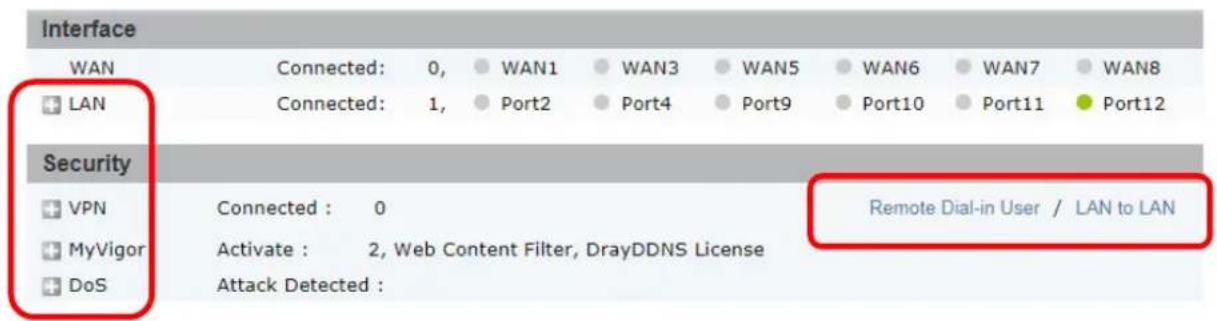
Note that there is a plus ( ) icon located on the left side of VPN/LAN. Click it to review the LAN connection(s) used presently.
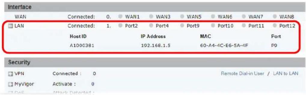
All of the hosts (including wireless clients) displayed with Host ID, IP Address and MAC address indicates that the traffic would be transmitted through LAN port(s) and then the WAN port. The purpose is to perform the traffic monitor of the host(s).
I-5-3 GUI Map



All the functions the router supports are listed with table clearly in this page. Users can click the function link to access into the setting page of the function for detailed configuration. Click the icon on the top of the main screen to display all the functions.
GUI Map
| Dashboard | Certificate Management | ||
| Online Status | Local Certificate | ||
| Physical Connection | Trusted CA Certificate | ||
| Virtual WAN | Certificate Backup | ||
| Port Setup | Self-Signed Certificate | ||
| WAN | SSL VPN | ||
| General Setup | General Setup | ||
| Internet Access | User Account | ||
| Multi-VLAN | USB Application | ||
| WAN Budget | USB General Settings | ||
| LAN | USB User Management | ||
| General Setup | File Explorer | ||
| VLAN | USB Disk Status | ||
| Bind IP to MAC | System Maintenance | ||
| Port Mirror/Packet Capture | System Status | ||
| PPPoE Server | TR-069 | ||
| Hotspot Web Portal | Administrator Password | ||
| Profile Setup | User Password | ||
| Quota Management | Login Page Greeting | ||
| Routing | Configuration Backup | ||
| Static Route | Configuration Export | ||
| Load-Balance/Route Policy | SysLog / Mail Alert | ||
| OSPF | Time and Date | ||
| BGP | SNMP | ||
| NAT | Management | ||
| Port Redirection | Self-Signed Certificate | ||
| DMZ Host | Reboot System | ||
| Open Ports | Firmware Upgrade | ||
| Port Triggering | Internal Service User List | ||
| ALG | Dashboard Control | ||
| Firewall | NAT Sessions | ||
I-5-4 Web Console
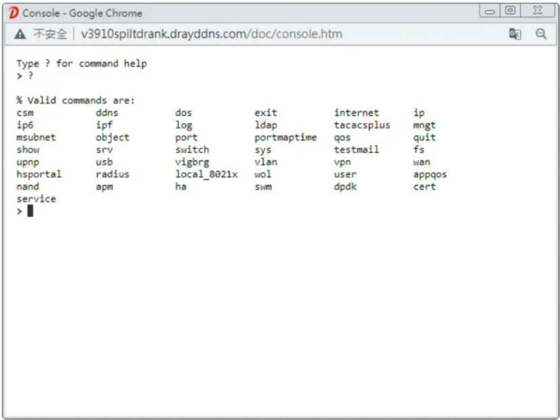
It is not necessary to use the telnet command via DOS prompt. The changes made by using web console have the same effects as modified through web user interface. The functions/ settings modified under Web Console also can be reviewed on the web user interface.
Click the Web Console icon on the top of the main screen to open the following screen.
I-5-5 Config Backup
There is one way to store current used settings quickly by clicking the Config Backup icon. It allows you to backup current settings as a file. Such configuration file can be restored by using System Maintenance>>Configuration Backup.
Simply click the icon on the top of the main screen.
I-5-6 Manual Download


Manual Download
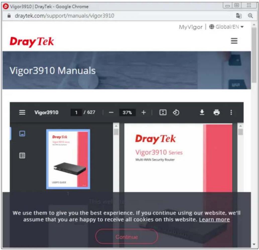
Click this icon to open online user's guide of Vigor router. This document offers detailed information for the settings on web user interface.
I-5-7 Logout


logout
Click this icon to exit the web user interface.
I-5-8 Online Status
Dashboard
Wizards
Online Status
Physical Connection
Virtual WAN
Search menu
I-5-8-1 Physical Connection
Such page displays the physical connection status such as LAN connection status, WAN connection status, ADSL information, and so on.
Physical Connection for IPv4 Protocol
Online Status
| Physical Connection | |||||
| IPv4 | IPv6 | ||||
| LAN Status | |||||
| IP Address | TX Packets | RX Packets | Router PrimaryDNS: | Router SecondaryDNS: | |
| 192.168.1.1 | 260,444 | 128,959 | 8.8.8.8 | 8.8.4.4 | |
| WAN 1 Status | |||||
| Enable | Line | Name | Mode | Up Time | |
| Yes | Ethernet | DHCP Client | 00:00:00 | ||
| IP | GW IP | TX Packets | TX Rate(Bps) | RX Packets | RX Rate(Bps) |
| --- | --- | 0 | 0 | 0 | 0 |
| WAN 3 Status | |||||
| Enable | Line | Name | Mode | Up Time | |
| Yes | Ethernet | DHCP Client | 00:00:00 | ||
| IP | GW IP | TX Packets | TX Rate(Bps) | RX Packets | RX Rate(Bps) |
| --- | --- | 0 | 0 | 0 | 0 |
| WAN 5 Status | |||||
| Enable | Line | Name | Mode | Up Time | |
| Yes | Ethernet | DHCP Client | 00:00:00 | ||
| IP | GW IP | TX Packets | TX Rate(Bps) | RX Packets | RX Rate(Bps) |
| --- | --- | 0 | 0 | 0 | 0 |
| WAN 6 Status | |||||
| Enable | Line | Name | Mode | Up Time | |
| Yes | Ethernet | DHCP Client | 00:00:00 | ||
| IP | GW IP | TX Packets | TX Rate(Bps) | RX Packets | RX Rate(Bps) |
| --- | --- | 0 | 0 | 0 | 0 |
| WAN 7 Status | |||||
| Enable | Line | Name | Mode | Up Time | |
| Yes | Ethernet | DHCP Client | 00:00:00 | ||
| IP | GW IP | TX Packets | TX Rate(Bps) | RX Packets | RX Rate(Bps) |
| --- | --- | 0 | 0 | 0 | 0 |
| WAN 8 Status | |||||
| Enable | Line | Name | Mode | Up Time | |
| Yes | Ethernet | DHCP Client | 00:00:00 | ||
| IP | GW IP | TX Packets | TX Rate(Bps) | RX Packets | RX Rate(Bps) |
| --- | --- | 0 | 0 | 0 | 0 |
Physical Connection for IPv6 Protocol
Online Status
| Physical Connection | System Uptime: 6days 7:14:46 | |||
| IPv4 | IPv6 | |||
| LAN Status | ||||
| IP Address | ||||
| FE80::21D:AAFF:FE4B:3E90/64 (Link) | ||||
| TX Packets | RX Packets | TX Bytes | RX Bytes | |
| 2,360 | 1,288 | 184,088 | 113,150 | |
| WAN1 IPv6 Status | ||||
| Enable | Mode | Up Time | ||
| No | Offline | --- | ||
| IP | Gateway IP | |||
| --- | --- | |||
| WAN3 IPv6 Status | ||||
| Enable | Mode | Up Time | ||
| No | Offline | --- | ||
| IP | Gateway IP | |||
| --- | --- | |||
| WAN5 IPv6 Status | ||||
| Enable | Mode | Up Time | ||
| No | Offline | --- | ||
| IP | Gateway IP | |||
| --- | --- | |||
| WAN6 IPv6 Status | ||||
| Enable | Mode | Up Time | ||
| No | Offline | --- | ||
| IP | Gateway IP | |||
| --- | --- | |||
| WAN7 IPv6 Status | ||||
| Enable | Mode | Up Time | ||
| No | Offline | --- | ||
| IP | Gateway IP | |||
| --- | --- | |||
| WAN8 IPv6 Status | ||||
| Enable | Mode | Up Time | ||
| No | Offline | --- | ||
| IP | Gateway IP | |||
| --- | --- | |||
Detailed explanation (for IPv4) is shown below:
| Item | Description |
| LAN Status Primary DNS-Displays the primary DNS server address for WAN interface.Secondary DNS -Displays the secondary DNS server address for WAN interface.IP Address-Displays the IP address of the LAN interface.TX Packets-Displays the total transmitted packets at the LAN interface.RX Packets-Displays the total received packets at the LAN interface. | |
| WAN1 to WAN8 Status Enable - Yes in red means such interface is available but not enabled. Yes in green means such interface is enabled.Line - Displays the physical connection (VDSL, ADSL, or Ethernet) of this interface.Name - Display the name of the router. | |
| Mode - Displays the type of WAN connection (e.g., PPPoE).Up Time - Displays the total uptime of the interface.IP - Displays the IP address of the WAN interface.GW IP - Displays the IP address of the default gateway.TX Packets - Displays the total transmitted packets at the WAN interface.TX Rate - Displays the speed of transmitted octets at the WAN interface.RX Packets - Displays the total number of received packets at the WAN interface.RX Rate - Displays the speed of received octets at the WAN interface. | |
Detailed explanation (for IPv6) is shown below:
| Item | Description |
| LAN Status IP Address- Displays the IPv6 address of the LAN interface. TX Packets-Displays the total transmitted packets at the LAN interface. RX Packets-Displays the total received packets at the LAN interface. TX Bytes - Displays the speed of transmitted octets at the LAN interface. RX Bytes - Displays the speed of received octets at the LAN interface. | |
| WAN1 to WAN8 IPv6 Status Enable - No in red means such interface is available but not enabled. Yes in green means such interface is enabled. No in red means such interface is not available. Mode - Displays the type of WAN connection (e.g., TSPC). Up Time - Displays the total uptime of the interface. IP - Displays the IP address of the WAN interface. Gateway IP - Displays the IP address of the default gateway. | |

Info
The words in green mean that the WAN connection of that interface is ready for accessing Internet; the words in red mean that the WAN connection of that interface is not ready for accessing Internet.
I-5-8-2 Virtual WAN
Such page displays the virtual WAN connection information.
Virtual WAN are used by TR-069 management, VoIP service and so on.
The field of Application will list i-9 the purpose of such WAN connection.
I-6 Quick Start Wizard
Quick Start Wizard can help you to deploy and use the router easily and quickly. Go to Wizards>>Quick Start Wizard. The first screen of Quick Start Wizard is entering login password. After typing the password, please click Next.
Wizards >> Quick Start Wizard
Enter login password
Please enter an alpha-numeric string as your Password (Max 83 characters)
Old Password
New Password
Confirm Password
Password Strength:
Strong password requirements:
-
Have at least one upper-case letter and one lower-case letter.
-
Including non-alphanumeric characters is a plus.
Hint: If you want to keep the password unchanged, leave the password blank and press "Next" button to skip this process.
< Back
Next>
Finish
Cancel
On the next page as shown below, please select the WAN interface that you use. If fiber is used, please choose WAN1/WAN2; if Ethernet is used, please choose WAN3 \~WANx. Then click Next for next step.
Quick Start Wizard
WAN Interface
WAN Interface:
Display Name:
Physical Mode:
Physical Type:
WAN3
MK-Tina
Ethernet
Auto negotiation ▼
< Back
Next>
Finish
Cancel
Fiber WAN and Etherent WAN will bring up different configuration page. Refer to the following for detailed information.
I-6-1 For WAN1 (Fiber)
WAN1 can be configured for physical mode of SFP+ (Fiber connection).
Quick Start Wizard
WAN Interface
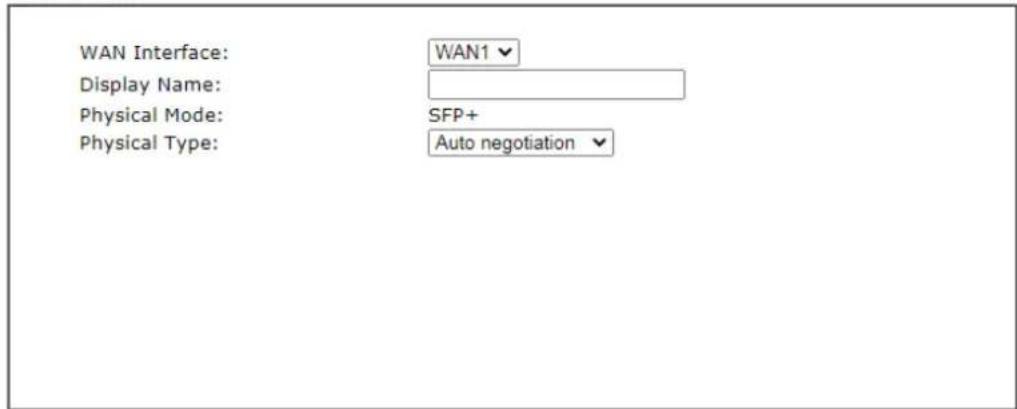

Available settings are explained as follows:
| Item | Description |
| Display Name Enter a name | for the router. |
| Physical Type This setting will vary based on the Physical Mode.In general,Auto negotiation is suggested. | |
On the next page as shown below, please select the appropriate Internet access type according to the information from your ISP. For example, you should select PPPoE mode if the ISP provides you PPPoE interface. Then click Next for next step.
Ethernet WAN1 - PPPoE
- Choose WAN1 as the WAN Interface. Click the Next button. The following page will be open for you to specify Internet Access Type.
Quick Start Wizard
Connect to Internet
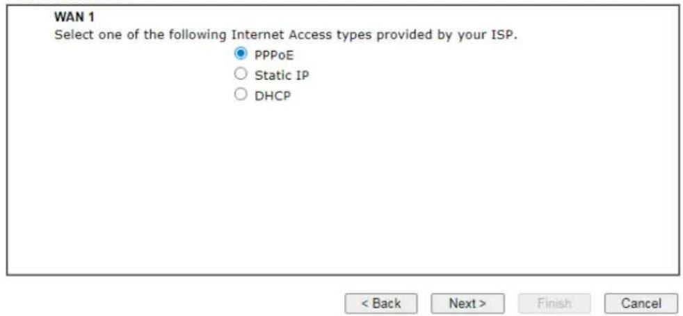
- Click PPPoE as the Internet Access Type to get the following page.
Quick Start Wizard
PPPoE Client Mode
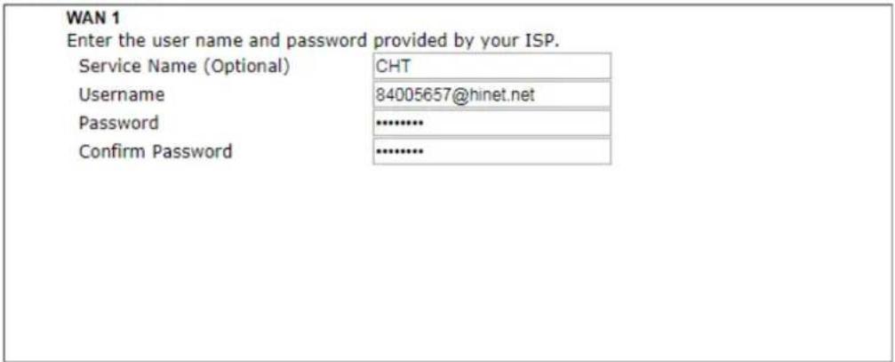

Available settings are explained as follows:
| Item | Description |
| Service Name(Optional) | Enter the description of the specific network service. |
| Username Assign a sp | specific valid user name provided by the ISP.Note: The maximum length of the user name you can set is 63 characters. |
| Password Assign a val | id password provided by the ISP.Note: The maximum length of the password you can set is 62 characters. |
| Confirm Password Re-enter the password. | |
| Back Click it to return to previous setting page. | |
| Next Click it to get into the next setting page. | |
| Cancel Click it to give up the quick start wizard. | |
- Please manually enter the Username/ Password provided by your ISP. Click Next for viewing summary of such connection.
Quick Start Wizard
Please confirm your settings:
WAN Interface: WAN1 Physical Mode: SFP+ Internet Access: PPPoE
Click Back to modify changes if necessary. Otherwise, click Finish to save the current settings and restart the Vigor router.

- Click Finish. A page of Quick Start Wizard Setup OK!!! will appear. Then, the system status of this protocol will be shown.
Quick Start Wizard Setup OK!
- Now, you can enjoy surfing on the Internet.
Ethernet WAN1 - Static IP
- Choose WAN1 as the WAN Interface. Click the Next button. The following page will be open for you to specify Internet Access Type.
Quick Start Wizard
Connect to Internet
WAN 1
Select one of the following Internet Access types provided by your ISP.
○ PPPoE
Static IP
○ DHCP

- Click Static IP as the Internet Access type to get the following page.
Quick Start Wizard
Static IP Client Mode
WAN 1
Enter the Static IP configuration provided by your ISP.
WAN IP
190.168.3.100
Subnet Mask
255.255.255.0
Gateway
192.168.3.1
Primary DNS
8.8.8.8
Secondary DNS
8.8.4.4
(optional)

Available settings are explained as follows:
| Item | Description |
| WAN IP Enter the IP address. | |
| Subnet Mask Enter the subnet mask. | |
| Gateway Enter the IP address of gateway. | |
| Primary DNS Enter the primary IP address for the router. | |
| Secondary DNS Enter the secondary IP address for necessity in the future. | |
| Back Click it to return to previous setting page. | |
| Next Click it to get into the next setting page. | |
| Cancel Click it to give up the quick start wizard. | |
- Please Enter the IP address information originally provided by your ISP. Then click Next for next step.
Quick Start Wizard
Please confirm your settings:
WAN Interface:
WAN1
Physical Mode:
SFP+
Internet Access:
Static IP
Click Back to modify changes if necessary. Otherwise, click Finish to save the current settings and restart the Vigor router.

- Click Finish. A page of Quick Start Wizard Setup OK!!! will appear. Then, the system status of this protocol will be shown.
Quick Start Wizard Setup OK!
- Now, you can enjoy surfing on the Internet.
Ethernet WAN1 - DHCP
- Choose WAN1 as the WAN Interface. Click the Next button. The following page will be open for you to specify Internet Access Type.
Quick Start Wizard
Connect to Internet
WAN 1
Select one of the following Internet Access types provided by your ISP.
○ PPPoE
○ Static IP
DHCP

- Click DHCP as the Internet Access type to get the following page.
Quick Start Wizard
DHCP Client Mode
WAN 1
If your ISP requires you to enter a specific host name or specific MAC address, please enter it in.
Host Name
MAC


Available settings are explained as follows:
| Item | Description |
| Host Name Enter the name of the host. | Note: The maximum length of the host name you can set is 39 characters. |
| MAC Some Cable service providers specify a specific MAC address for access authentication. In such cases you need to enter the MAC address. | |
| Back Click it to return to previous setting page. | |
| Next Click it to get into the next setting page. | |
Cancel Click it to give up the quick start wizard.
- After finished the settings above, click Next for viewing summary of such connection.
Quick Start Wizard
Please confirm your settings:
WAN Interface: WAN1
Physical Mode: SFP+
Internet Access: DHCP
Click Back to modify changes if necessary. Otherwise, click Finish to save the current settings and restart the Vigor router.

- Click Finish. A page of Quick Start Wizard Setup OK!!! will appear. Then, the system status of this protocol will be shown.
Quick Start Wizard Setup OK!
- Now, you can enjoy surfing on the Internet.
I-6-2 For WAN3 (Ethernet - 2.5G)
WAN3 shall be used for connection with rate 2.5G.
Quick Start Wizard
WAN Interface

Available settings are explained as follows:
| Item | Description |
| Display Name Enter a name | for the router. |
| Physical Type This setting will vary based on the Physical Mode.In general,Auto negotiation is suggested. | |
On the next page as shown below, please select the appropriate Internet access type according to the information from your ISP. For example, you should select PPPoE mode if the ISP provides you PPPoE interface. Then click Next for next step.
Ethernet WAN3 - PPPoE
- Choose WAN3 as the WAN Interface. Click the Next button. The following page will be open for you to specify Internet Access Type.
Quick Start Wizard
Connect to Internet
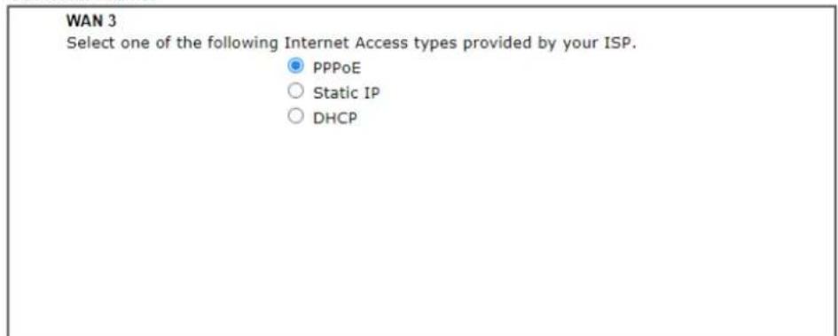

- Click PPPoE as the Internet Access Type to get the following page.
Quick Start Wizard
PPPoE Client Mode
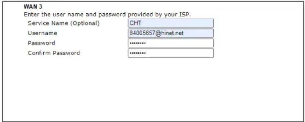

Available settings are explained as follows:
| Item | Description |
| Service Name(Optional) | Enter the description of the specific network service. |
| Username Assign a sp | specific valid user name provided by the ISP.Note:The maximum length of the user name you can set is 63 characters. |
| Password Assign a val | id password provided by the ISP.Note:The maximum length of the password you can set is 62 characters. |
| Confirm Password Re | enter the password. |
| Back Click it to return | to previous setting page. |
| Next Click it to get into | to the next setting page. |
| Cancel Click it to give | up the quick start wizard. |
- Please manually enter the Username/ Password provided by your ISP. Click Next for viewing summary of such connection.
Quick Start Wizard
Please confirm your settings:
WAN Interface:
WAN3
Physical Mode:
Ethernet
Internet Access:
PPPoE
Click Back to modify changes if necessary. Otherwise, click Finish to save the current settings and restart the Vigor router.
< Back
Next>
Finish
Cancel
- Click Finish. A page of Quick Start Wizard Setup OK!!! will appear. Then, the system status of this protocol will be shown.
Quick Start Wizard Setup OK!
- Now, you can enjoy surfing on the Internet.
Ethernet WAN3 - Static IP
- Choose WAN3 as the WAN Interface. Click the Next button. The following page will be open for you to specify Internet Access Type.
Quick Start Wizard
Connect to Internet
WAN 3
Select one of the following Internet Access types provided by your ISP.
○ PPPoE
Static IP
DHCP
< Back
Next >
Finish
Cancel
- Click Static IP as the Internet Access type to get the following page.
Quick Start Wizard
Static IP Client Mode
WAN 3
Enter the Static IP configuration provided by your ISP.
WAN IP
172.16.21.77
Subnet Mask
255.255.255.0
Gateway
172.16.21.1
Primary DNS
8.8.8.8
Secondary DNS
8.8.4.4
(optional)
< Back
Next >
Finish
Cancel
Available settings are explained as follows:
| Item | Description |
| WAN IP Enter the IP address. | |
| Subnet Mask Enter the subnet mask. | |
| Gateway Enter the IP address of gateway. | |
| Back Click it to return to previous setting page. | |
| Next Click it to get into the next setting page. | |
| Cancel Click it to give up the quick start wizard. | |
- Please enter the IP address information originally provided by your ISP. Then click Next for next step.
Quick Start Wizard
Please confirm your settings:
WAN Interface:
WAN3
Physical Mode:
Ethernet
Internet Access:
Static IP
Click Back to modify changes if necessary. Otherwise, click Finish to save the current settings and restart the Vigor router.

- Click Finish. A page of Quick Start Wizard Setup OK!!! will appear. Then, the system status of this protocol will be shown.
Quick Start Wizard Setup OK!
- Now, you can enjoy surfing on the Internet.
Wireless WAN3 - DHCP
- Choose WAN3 as the WAN Interfac. Click the Next button. The following page will be open for you to specify Internet Access Type.
Quick Start Wizard
Connect to Internet
WAN 3
Select one of the following Internet Access types provided by your ISP.
○ PPPoE
○ Static IP
DHCP

- Click DHCP as the Internet Access type to get the following page.
Quick Start Wizard
DHCP Client Mode
WAN 3
If your ISP requires you to enter a specific host name or specific MAC address, please enter it in.
Host Name
MAC


Available settings are explained as follows:
| Item | Description |
| Host Name Enter the name of the host. | Note: The maximum length of the host name you can set is 39 characters. |
| MAC Some Cable service providers specify a specific MAC address for access authentication. In such cases you need to enter the MAC address. | |
| Back Click it to return to previous setting page. | |
| Next Click it to get into the next setting page. | |
Cancel Click it to give up the quick start wizard.
- After finished the settings above, click Next for viewing summary of such connection.
Quick Start Wizard
Please confirm your settings:
WAN Interface:
WAN3
Physical Mode:
Ethernet
Internet Access:
DHCP
Click Back to modify changes if necessary. Otherwise, click Finish to save the current settings and restart the Vigor router.

- Click Finish. A page of Quick Start Wizard Setup OK!!! will appear. Then, the system status of this protocol will be shown.
Quick Start Wizard Setup OK!
- Now, you can enjoy surfing on the Internet.
I-6-3 For WAN5\~WAN8 (Etherent)
WAN5\~WAN8 can be configured for physical mode of Ethernet.
Quick Start Wizard
WAN Interface
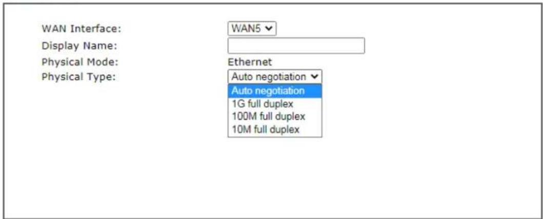

Available settings are explained as follows:
| Item | Description |
| Display Name Enter a name | for the router. |
| Physical Type This setting will vary based on the Physical Mode.In general, Auto negotiation is suggested. | |
On the next page as shown below, please select the appropriate Internet access type according to the information from your ISP. For example, you should select PPPoE mode if the ISP provides you PPPoE interface. Then click Next for next step.
Ethernet WAN5 - PPPoE
- Choose WAN5 as the WAN Interface. Click the Next button. The following page will be open for you to specify Internet Access Type.
Connect to Internet
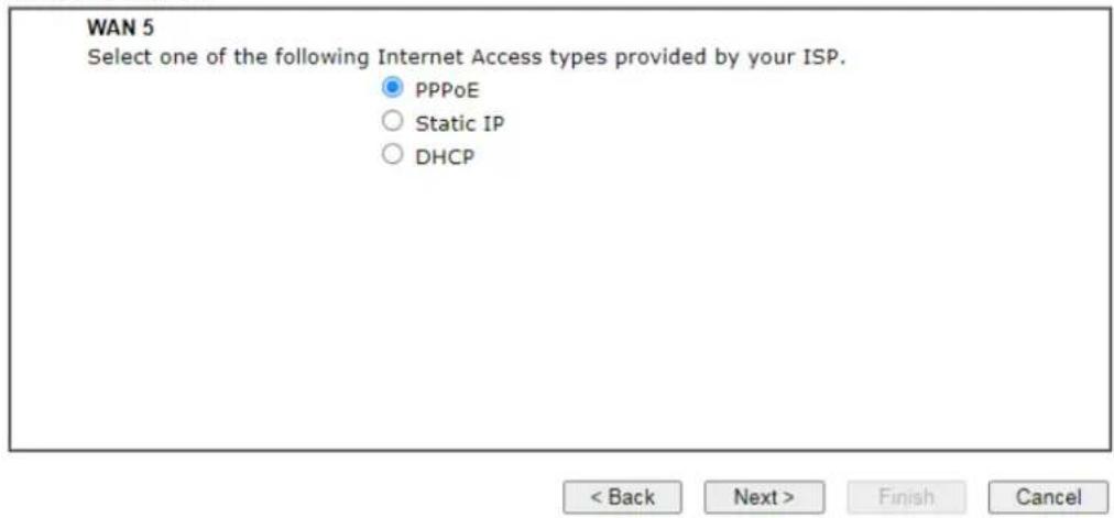
- Click PPPoE as the Internet Access Type to get the following page.
Quick Start Wizard
PPPoE Client Mode
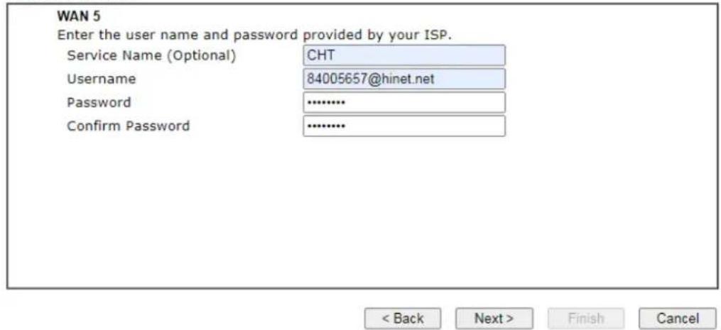
Available settings are explained as follows:
| Item | Description |
| Service Name(Optional) | Enter the description of the specific network service. |
| Username Assign a sp | specific valid user name provided by the ISP.Note: The maximum length of the user name you can set is 63 characters. |
| Password Assign a val | id password provided by the ISP.Note: The maximum length of the password you can set is 62 characters. |
| Confirm Password Re-enter the password. | |
| Back Click it to return | to previous setting page. |
| Next Click it to get into the next setting page. | |
| Cancel Click it to give | up the quick start wizard. |
- Please manually enter the Username/ Password provided by your ISP. Click Next for viewing summary of such connection.
Quick Start Wizard
Please confirm your settings:
WAN Interface:
WAN5
Physical Mode:
Ethernet
Internet Access:
PPPoE
Click Back to modify changes if necessary. Otherwise, click Finish to save the current settings and restart the Vigor router.
< Back
Next>
Finish
Cancel
- Click Finish. A page of Quick Start Wizard Setup OK!!! will appear. Then, the system status of this protocol will be shown.
Quick Start Wizard Setup OK!
- Now, you can enjoy surfing on the Internet.
Ethernet WAN5 - Static IP
- Choose WAN5 as the WAN Interface. Click the Next button. The following page will be open for you to specify Internet Access Type.
Quick Start Wizard
Connect to Internet
WAN 5
Select one of the following Internet Access types provided by your ISP.
○ PPPoE
Static IP
DHCP

- Click Static IP as the Internet Access type to get the following page.
Quick Start Wizard
Static IP Client Mode
WAN 5
Enter the Static IP configuration provided by your ISP.
WAN IP
Subnet Mask
Gateway
Primary DNS
Secondary DNS
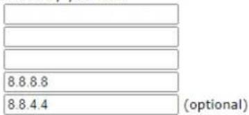

Available settings are explained as follows:
| Item | Description |
| WAN IP Enter the IP address. | |
| Subnet Mask Enter the subnet mask. | |
| Gateway Enter the IP address of gateway. | |
| Back Click it to return to previous setting page. | |
| Next Click it to get into the next setting page. | |
| Cancel Click it to give up the quick start wizard. | |
- Please enter the IP address information originally provided by your ISP. Then click Next for next step.
Quick Start Wizard
Please confirm your settings:
WAN Interface:
WAN5
Physical Mode:
Ethernet
Internet Access:
Static IP
Click Back to modify changes if necessary. Otherwise, click Finish to save the current settings and restart the Vigor router.

- Click Finish. A page of Quick Start Wizard Setup OK!!! will appear. Then, the system status of this protocol will be shown.
Quick Start Wizard Setup OK!
- Now, you can enjoy surfing on the Internet.
Wireless WAN5 - DHCP
- Choose WAN5 as the WAN Interfac. Click the Next button. The following page will be open for you to specify Internet Access Type.
Quick Start Wizard
Connect to Internet
WAN 5
Select one of the following Internet Access types provided by your ISP.
○ PPPoE
○ Static IP
DHCP

- Click DHCP as the Internet Access type to get the following page.
Quick Start Wizard
DHCP Client Mode
WAN 5
If your ISP requires you to enter a specific host name or specific MAC address, please enter it in.
Host Name
MAC


Available settings are explained as follows:
| Item | Description |
| Host Name Enter the name of the host. | |
| MAC Some Cable service providers specify a specific MAC address for access authentication. In such cases you need to enter the MAC address. | |
| Back Click it to return to previous setting page. | |
| Next Click it to get into the next setting page. | |
Cancel Click it to give up the quick start wizard.
- After finished the settings above, click Next for viewing summary of such connection.
Quick Start Wizard
Please confirm your settings:
WAN Interface:
WAN5
Physical Mode:
Ethernet
Internet Access:
DHCP
Click Back to modify changes if necessary. Otherwise, click Finish to save the current settings and restart the Vigor router.

- Click Finish. A page of Quick Start Wizard Setup OK!!! will appear. Then, the system status of this protocol will be shown.
Quick Start Wizard Setup OK!
- Now, you can enjoy surfing on the Internet.
I-7 Service Activation Wizard
Service Activation Wizard can guide you to activate WCF service (Web Content Filter) with a quick and easy way. For the Service Activation Wizard is only available for admin operation, therefore, please type “admin/admin” on Username/Password while Logging into the web user interface.
Service Activation Wizard is a tool which allows you to use trial version of WCF directly without accessing into the server (MyVigor) located on http://myvigor.draytek.com. For using Web Content Filter Profile, please refer to later section Web Content Filter Profile for detailed information.
Now, follow the steps listed below to activate WCF feature for your router.

Info Such function is available only for Admin Mode.
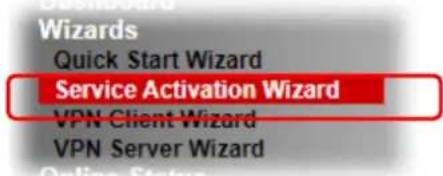
- Open Wizards>>Service Activation Wizard.
- The screen of Service Activation Wizard will be shown as follows. You can activate the Web content filter services and/or DDNS service at the same time or individually. When you finish the selection, please click Next.
Service Activation Wizard
Select the service type that you want to activate
Activation Date: 2021-04-19
Web Content Filter(WCF) Service :

Dynamic DNS(DDNS) Service :

Domain Name : 2019101610520701 .drayddns.com


Info
● BPjM is web content filter (WCF) for German Speaking users. It is ideal for your family to provide more Internet security for youngsters.
● Cryan 30-day trial is WCF which offers 30-day trial period.
- DT-DDNS, developed by DrayTek, offers one year free charge service of dynamic DNS service for internal use.
- Setting confirmation page will be displayed as follows, please click Activate.
Service Activation Wizard
Please confirm your settings
Sevice Type : Trial version Sevice Activated : Web Content Filter (BPjM)
Please click Back to re-select service type you to activate.


Info
The service will be activated and applied as the default rule configured in Firewall>>General Setup.
- The web page will display the service that you have activated according to your selection(s).
I-8 Registering Vigor Router
You have finished the configuration of Quick Start Wizard and you can surf the Internet at any time. Now it is the time to register your Vigor router to MyVigor website for getting more service. Please follow the steps below to finish the router registration.
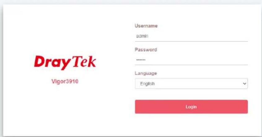
1 Please login the web configuration interface of Vigor router by typing "admin/admin" as User Name / Password.
Copyright © 2021 DrayTek Corp
2 Click Support Area>>Production Registration from the home page.
Support Area Product Registration Service Status
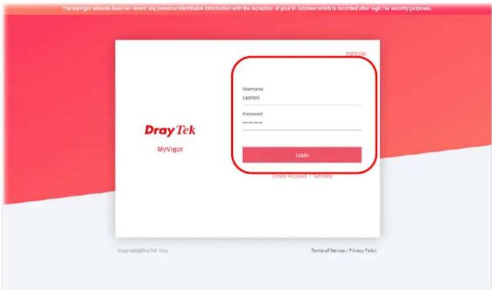
3 A Login page will be shown on the screen. Please type the account and password that you created previously. And click Login.

Info
If you haven't an accessing account, please refer to section Creating an Account for MyVigor to create your own one. Please read the articles on the Agreement regarding user rights carefully while creating a user account.
4 The following page will be displayed after you logging in MyVigor. Type a nickname for the router, then click Submit.
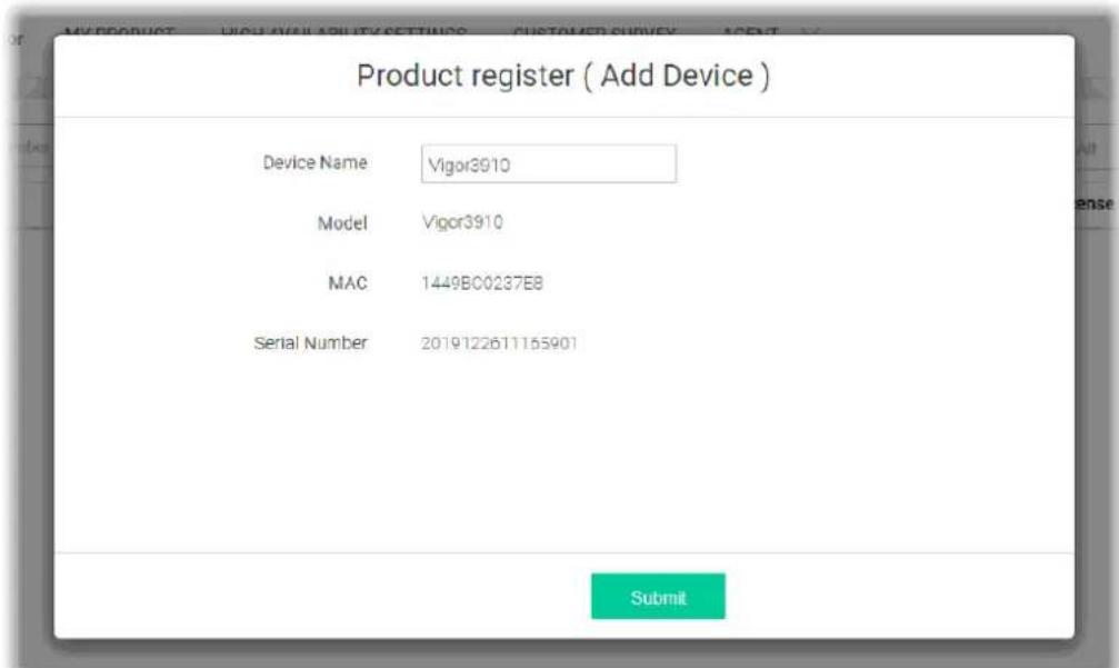
5 When the following page appears, your router information has been added to the database. Your router has been registered to myvigor website successfully.
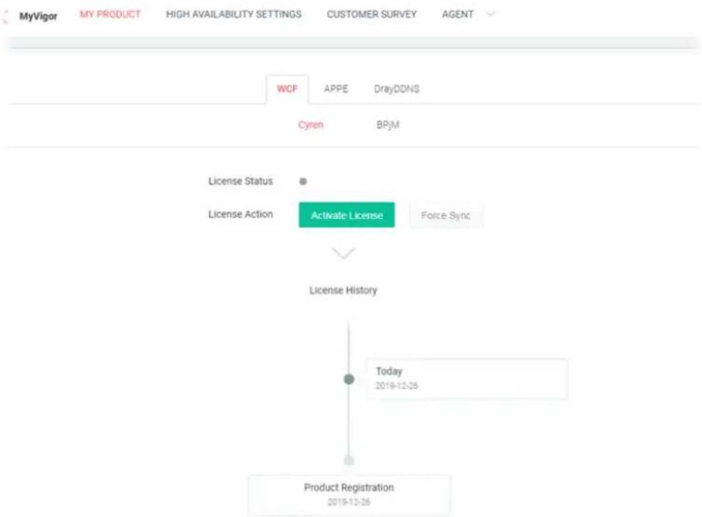
flowchart
graph TD
    A["License Status"] --> B["License Action"]
    B --> C["Activate License"]
    C --> D["Force Sync"]
    D --> E["License History"]
    E --> F["Today 2019-12-26"]
    F --> G["Product Registration 2019-12-26"]
6 Clicking MYPRODUCT for viewing the general information of the registered router on MyVigor website.
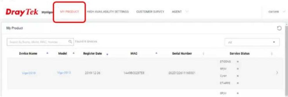
I-9 VPN Client Wizard
The VPN Client Wizard will configure the router as a client to connect to a remote VPN server using a LAN-to-LAN VPN tunnel. The wizard will guide you through the setup process.
- On the menu bar, click on Wizards, and then VPN Client Wizard.
VPN Client Wizard
Choose VPN Establishment Environment
Please choose a LAN-to-LAN Profile:
1 x ???
< Back Next > Finish Cancel
Available settings are explained as follows:
| Item | Description |
| Please choose a LAN-to-LAN Profile | The profile used to store this tunnel configuration.Selecting an index that has already been setup previously will result in the existing setup getting overwritten by the wizard. |
- When you finish the mode and profile selection, please click Next to open the following page.
VPN Client Wizard
VPN Connection Setting
Security Ranking:
Very High
IPsec XAuth
IPsec IKEv2 EAP (only for NAT Mode)
L2TP over IPSec
OpenVPN (AES256)
High
IPSec IKEv1/IKEv2
SSL
OpenVPN (AES128)
Medium
PPTP (Encryption)
Low
L2TP / PPTP (None Encryption)
OpenVPN (None Encryption)
LAN-to-LAN VPN Client Mode Selection:
Select VPN Type:
Throughput Ranking:
Very High
L2TP / PPTP (None Encryption)
High
IPSec IKEv2/EAP/IKEv1/XAuth
OpenVPN (UDP None Encryption)
Medium
L2TP over IPSec / PPTP (Encryption)
OpenVPN (UDP)
OpenVPN (TCP None Encryption)
Low
SSL/OpenVPN (TCP)
Route Mode
PPTP (Encryption)
Note:
- Please use Route Mode for typical LAN-to-LAN tunnels.
- If the remote network is only expecting a single client or IP and is not configured to route the subnet then select
NAT Mode - If you are unsure of your configuration select Route Mode.
< Back
Next>
Finish
Cancel
Available settings are explained as follows:
| Item | Description |
| LAN-to-LAN Client Mode Selection | Route Mode - All traffic between the local network and the remote network bear the originating IP addresses. Select this if the VPN server can establish routes to handle inter-LAN traffic routing.NAT Mode - The VPN client (local router) uses a single IP address assigned by the VPN server (remote router) and uses NAT to keep track of the connections. Select this if the VPN server expects only one IP address on the local network to communicate with the remote network. |
| Select VPN Type Select | a VPN protocol for the LAN-to-LAN tunnel. Different VPN protocols offer different levels or security and performance. |

Info
The following descriptions for VPN Type are based on the Route Mode specified in LAN-to-LAN Client Mode Selection.
If you have selected PPTP (None Encryption) or PPTP (Encryption), the following configuration screen appears.
VPN Client Wizard
VPN Client PPTP Encryption Settings
| Profile Name | ??? |
| VPN Dial-Out Through | WAN1 First |
| □ Always on | |
| Server IP/Host Name for VPN(e.g. draytek.com or 123.45.67.89) | |
| Username | ??? |
| Password | |
| Remote Network IP | 0.0.0.0 |
| Remote Network Mask | 255.255.255.0 / 24 |
| Local Network IP | 192.168.1.1 |
| Local Network Mask | 255.255.255.0 / 24 |
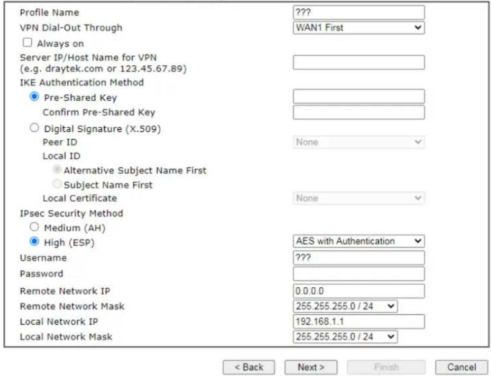
If you have selected IPsec, the following configuration screen appears.
VPN Client Wizard
VPN Client IPsec Settings
| Profile Name | ??? |
| VPN Dial-Out Through | WAN1 First |
| □ Always on | |
| Server IP/Host Name for VPN(e.g. draytek.com or 123.45.67.89) | |
| IKE Authentication Method | |
| ● Pre-Shared Key | |
| Confirm Pre-Shared Key | |
| ○ Digital Signature (X.509) | |
| Peer ID | None |
| Local ID | |
| ● Alternative Subject Name First | |
| ○ Subject Name First | |
| Local Certificate | None |
| IPsec Security Method | |
| ○ Medium (AH) | |
| ● High (ESP) | AES with Authentication |
| Remote Network IP | 0.0.0.0 |
| Remote Network Mask | 255.255.255.0 / 24 |
| Local Network IP | 192.168.1.1 |
| Local Network Mask | 255.255.255.0 / 24 |

If you have selected SSL/L2TP, the following configuration screen appears.
VPN Client Wizard
VPN Client L2TP Settings

If you have selected L2TP over IPsec (Nice to Have) or L2TP over IPsec (Must), the following configuration screen appears.
VPN Client Wizard
VPN Client L2TP over IPsec (Nice to Have) Settings
If you have selected OpenVPN, the following configuration screen appears.
VPN Client OpenVPN Encryption Settings
| Profile Name | ??? |
| VPN Dial-Out Through | WAN1 First |
| Import OpenVPN config file | 選擇檔案 未選擇任何檔案 |
| □ Always on | |
| Username | ??? |
| Password | Max: 128 characters |
| Local Network IP | 192.168.1.1 |
| Local Network Mask | 255.255.255.0 / 24 |

Available settings are explained as follows:
| Item | Description |
| Profile Name Name that identifies this profile. The maximum length of the Profile Name is 10 characters. | |
| VPN Dial-Out Through | The WAN interface to be used for dialing out to establish the VPN tunnel.WANx First - The Router first attempts to establish the VPN tunnel using this WAN interface. When that is unsuccessful, it will attempt to use other WAN interfaces.WANx Only - The Router will establish the VPN tunnel using this WAN interface only. |
| Always On If selected, | the router will maintain the VPN connection. |
| Server IP/Host Name for VPN | Enter the IP address or hostname of the server of the remote VPN server. |
| IKE Authentication Method | IKE Authentication Method to be used. Choose between Pre-shared Key and Digital Signature (X.509).Pre-shared KeyPre-Shared Key- Specify a key for IKE authentication.Confirm Pre-Shared Key-Confirm the pre-shared key.Digital Signature (X.509)Peer ID - Select Peer ID from the dropdown list. Peer IDs are managed using VPN and Remote Access >> IPsec Peer Identity.Local ID - Select Alternative Subject Name First or Subject Name First.Local Certificate - Select a certificate from the dropdown list. Local certificates are managed using Certificate Management >> Local Certificate. |
| IPsec Security Method | Medium - Authentication Header (AH) means data will be authenticated, but not be encrypted. By default, this optionis active.High - Encapsulating Security Payload (ESP) means payload (data) will be encrypted and authenticated. You may select encryption algorithm from Data Encryption Standard (DES), Triple DES (3DES), and AES. |
| Import OpenVPN config file | Select to import an OpenVPN configuration file from a specified OpenVPN server (e.g., Vigor router, PC, other VPN provider and etc.) onto to Vigor router.Later, as a VPN client, this router can access into VPN server via the username and password. |
| Username | This field is used to authenticate for connection when you select PPTP or L2TP with or without IPsec policy above.The length of the user name is limited to 11 characters. |
| Password | This field is used to authenticate for connection when you select PPTP or L2TP with or without IPsec policy above.The length of the password is limited to 11 characters. |
| Remote Network IP Please enter one LAN IP address (according to the real location of the remote host) for building VPN connection. | |
| Remote Network Mask | Please enter the network mask (according to the real location of the remote host) for building VPN connection. |
| Local Network IP Enter | the local network IP for TCP / IP configuration. |
| Local Network Mask Enter | the local network mask for TCP / IP configuration. |
- After you have entered all the required information, click Next to proceed to the confirmation page. The confirmation page shows a summary of all the settings. If you need to make adjustments to the settings, click Back to return to the previous page. Otherwise, select one of the following actions and click Finish to save the changes to the LAN-to-LAN VPN profile.
VPN Client Wizard
Please confirm your settings
| LAN-to-LAN Index: | 1 |
| Profile Name: | Marketing1 |
| VPN Connection Type: | L2TP over IPsec (Nice to Have) |
| VPN Dial-Out Through: | WAN1 First |
| Always on: | Yes |
| Server IP/Host Name: | 172.16.3.8 |
| IKE Authentication Method: | Pre-Shared Key |
| IPsec Security Method: | AES with Authentication |
| Remote Network IP: | 172.16.3.100 |
| Remote Network Mask: | 255.255.255.0 |
| Local Network IP: | 192.168.1.1 |
| Local Network Mask: | 255.255.255.0 |
< Back Next > Finish Cancel
Available settings are explained as follows:
| Item | Description |
| Go to the VPN Connection Management | Proceed to VPN and Remote Access>>Connection Management to manage VPN sessions. |
| Do another VPN Client Wizard Setup | Rerun the VPN Client Wizard to configure another LAN-to-LAN VPN profile. |
| View more detailed configuration | Open this profile in VPN and Remote Access>>LAN to LAN to make additional configuration changes. |
I-10 VPN Server Wizard
The VPN Server Wizard can be used to set the router up as a server that accepts inbound VPN connections from a VPN server using a LAN-to-LAN VPN tunnel.
Site-to-Site (LAN-to-LAN)
- A connection between two router's LAN networks.
- Allows employees in branch offices and head office to share the same network resources.

flowchart
graph LR
    A["Local Network 192.168.1.0/24"] --> B["Network"]
    B --> C["Internet"]
    C --> D["Remote Network 172.16.2.0/24"]
    B --> E["VPN Tunnel"]
    E --> D
Remote Access (Remote Dial-in)
- A connection between the remote host and router's LAN network. The host will use an IP address in the local subnet.
- Allows employees to access the company's internal resources when they are traveling.

flowchart
graph LR
    A["Local Network 192.168.1.0/24"] --> B["Network"]
    B --> C["Internet\nVPN Tunnel"]
    C --> D["Remote Host 192.168.1.100"]
The wizard will guide you step by step through the setup process.
- On the menu bar, click on Wizards, and then VPN Server Wizard.
VPN Server Wizard
Choose VPN Establishment Environment
![VPN Server Mode Selection: Site to Site VPN (LAN-to-LAN) Please choose a LAN-to-LAN Profile: [Index] [Status] [Name] Please choose a Dial-in User Accounts: [Index] [Status] [Name] Allowed Dial-in Type: PPTP IPsec IPsec XAuth L2TP with IPsec Policy None SSL Tunnel OpenVPN Tunnel](/content/2026/05/813922/images/32983b93dbc6ff21eedfd0c61c1aee032cb8bb7d7ccf7cc1385a3572d2e041c4.jpg)

Available settings are explained as follows:
| Item | Description |
| VPN Server Mode Selection | Type of VPN Server to be configured.Site to Site VPN (LAN-to-LAN) - Configures the VPN server for inbound connections from other routers.Remote Dial-in User (Teleworker) - Configures VPN server for inbound connections from remote users. |
| Please choose a LAN-to-LAN Profile | If the VPN Server Mode selected was Site to Site VPN (LAN-to-LAN), choose a LAN-to-LAN profile to store this configuration. |
| Please choose a Dial-in User Accounts | If the VPN Server Mode selected was Remote Dial-in User (Teleworker), choose a Dial-in user profile to store this configuration. |
| Allowed Dial-in Type | Select all VPN protocols that are allowed for this LAN-to-LAN Profile or Dial-in User Account.Different Dial-in Type will lead to different configuration page. In addition, adjustable items for each dial-in type will be changed according to the VPN Server Mode (Site to Site VPN and Remote Dial-in User) selected. |
- After making the choices for the server profile, please click Next.
- The following dialog box appears, reminding you to not configure IPsec fields if the remote location has a dynamic IP address.
192.168.1.1
If you are using IPsec Main mode and the remote VPN gateway has a dynamic IP address, please don't setup "PeerIP" or "Peer ID" fields, and don't tick "IPsec Authentication". Instead, please go to the VPN and Remote Access >> IPsec General Setup page to setup a common preshared key.
确定
Click OK to dismiss the dialog box and proceed to the next page.
If you have chosen to configure a LAN-to-LAN VPN profile, proceed to step 4.
If you have chosen to configure a Remote Dial-in User VPN profile, proceed to step 5.
- The Site to Site VPN (LAN-to-LAN) configuration page appears as follows if you have selected PPTP/SSL.
VPN Server Wizard
VPN Authentication Setting
Profile Name
PPTP / SSL Tunnel Authentication
Username
Password
Peer IP/VPN Client IP
Site to Site Information
Remote Network IP
Remote Network Mask
Local Network IP
Local Network Mask
???
???
0.0.0.0
255.255.255.0 / 24
192.168.1.1
255.255.255.0/24
< Back
Next>
Finish
Cancel
If you have selected PPTP & IPsec & L2TP (three types) or PPTP & IPsec (two types) or L2TP with Policy (Nice to Have/Must), the following configuration screen appears.
VPN Server Wizard
VPN Authentication Setting
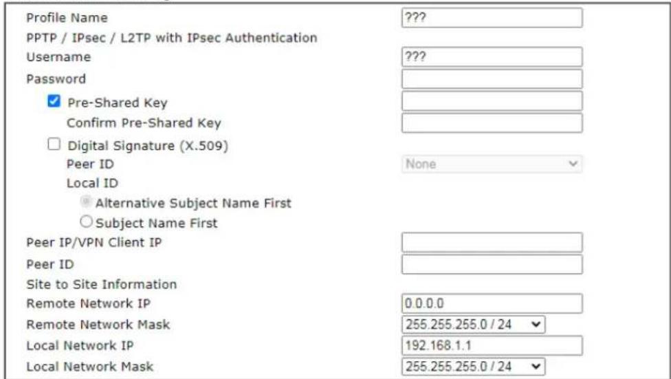

If you have selected IPsec, the following configuration screen appears.
VPN Server Wizard
VPN Authentication Setting
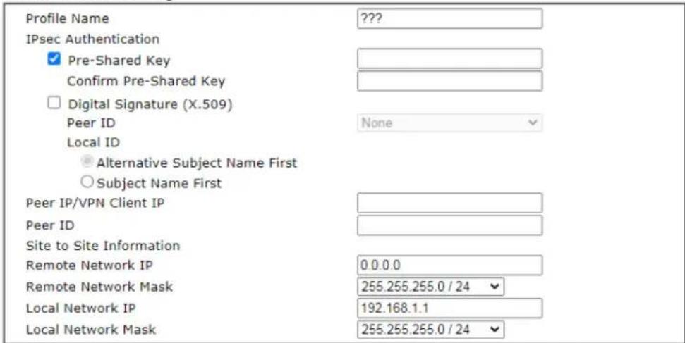

If you have selected OpenVPN, the following configuration screen appears.
VPN Server Wizard
VPN Authentication Setting
| Profile Name | ??? |
| OpenVPN Tunnel Authentication | |
| Username | ??? |
| Password | Max: 128 characters |
| Peer IP/VPN Client IP | |
| Site to Site Information | |
| Remote Network IP | 0.0.0.0 |
| Remote Network Mask | 255.255.255.0 / 24 |
| Local Network IP | 192.168.1.1 |
| Local Network Mask | 255.255.255.0 / 24 |
OpenVPN General Setup
| Certificates Setup | ||
| Generated certificates | Root Certificate: | None |
| Server Certificate: | None | |
| Client Certificate: | None | |
| Trust Certificate: | None | |
| Generate | ||
| Note:OpenVPN authentication is based on certificates.You may either generate new (by clicking "Generate" button) or upload existing certificates to the following path:1. Upload Server Certificate to Certificate Management >> Local Certificate2. Upload Trusted Certificate to Certificate Management >> Trusted CA Certificate | ||

Available settings are explained as follows:
| Item | Description |
| Profile Name Name to | identify this VPN profile. |
| User Name Used by the | remote LAN to establish a VPN connection.The length of the user name is limited to 11 characters. |
| Password Used by the | remote LAN to establish a VPN connection.The length of the password is limited to 11 characters. |
| IPsec / IPsec XAuth / L2TP with IPsec / SSL Tunnel Authentication | |
| Pre-Shared Key For PPTP / IPsec / IPsec XAuth / L2TP with IPsec / SSL Tunnel authentication, you have to configure a pre-shared key and/or digital signature.Note that, if the remote client has a dynamic IP address, do not enable any of the settings (PSK / Digital Signature) in this section. Instead, configure the global IPsec settings by using VPN and Remote Access>>IPsec General Setup.Pre-Shared Key - Select to enter an IPsec Pre-shared Key specific to this profile. The length of the PSK is limited to 64 | |
| characters. Confirm Pre-Shared Key - Re-enter the Pre-shared Key again to confirm. | |
| Digital Signature (X.509) | Digital Signature (X.509) - Select to enable X.509 digital signature. Peer ID - Select a predefined X.509 digital signature as the Peer ID. Peer IDs must be configured first using VPN and Remote Access>>IPsec Peer Identity. Local ID - Specifies whether the Subject Name or the Alternative Subject Name of the X.509 Peer ID is to be checked first. Select either Alternative Subject Name First or Subject Name First. |
| Peer IP/VPN Client IP | Enter the WAN IP address or VPN client IP address for the remote client. If values are specified, only connections coming from the specified IP address and/or having the specified Peer ID will be accepted. |
| Peer ID Enter the ID name for the remote client. The maximum length of the peer ID is 47 characters. If the values are specified, only connections coming from the specified IP address and/or having the specified Peer ID will be accepted. | |
| Site to Sit Information | |
| Remote Network IP | Enter the IP address of the remote network. |
| Remote Network Mask | Enter the subnet mask of the remote network. |
| Local Network IP Enter | the local network IP for TCP / IP configuration. |
| Local Network Mask Enter the local network mask for TCP / IP configuration. | |
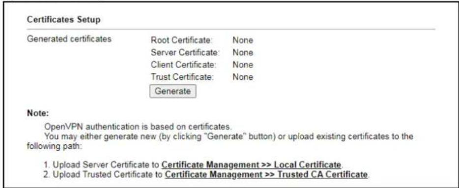
| OpenVPN General Setup | Generate - Click to generate certificate for OpenVPN authentication. Or upload an existing certificate from Local Certificate or Trusted CA Certificate page. |
- The Remote Dial-in User (Teleworker) VPN configuration page appears as follows if you have selected PPTP/SSL.
VPN Server Wizard
VPN Authentication Setting
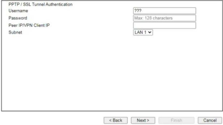
If you have selected IPsec XAuth/L2TP with IPsec Policy (None), the following configuration screen appears.
VPN Server Wizard
VPN Authentication Setting
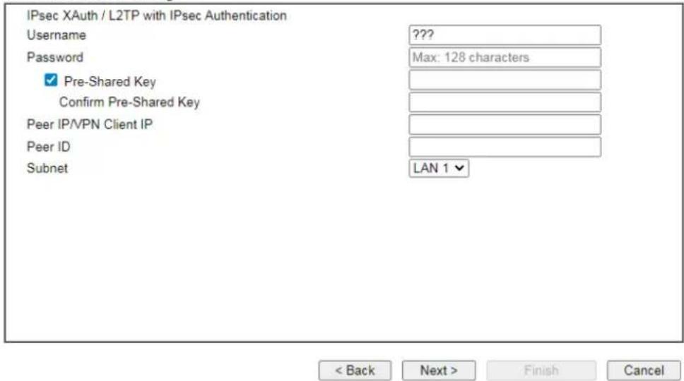
If you have selected IPsec XAuth/L2TP with IPsec Policy (Nice to Have)/L2TP with IPsec Policy (Must), the following configuration screen appears.
VPN Server Wizard
VPN Authentication Setting
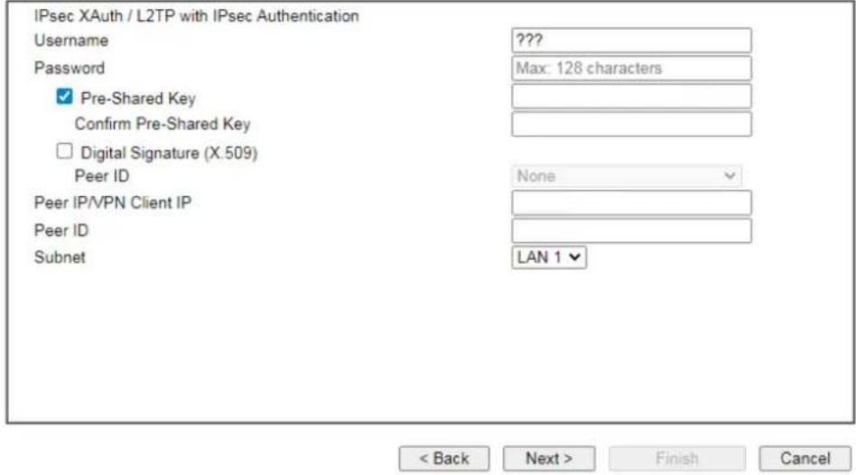
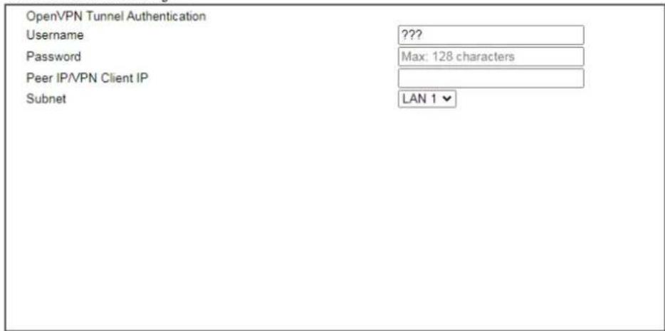
If you have selected OpenVPN Tunnel, the following configuration screen appears.
VPN Server Wizard
VPN Authentication Setting
OpenVPN General Setup

Available settings are explained as follows:
| Item | Description |
| User Name Used by the | remote LAN to establish a VPN connection.The length of the user name is limited to 11 characters. |
| Password Used by the | remote LAN to establish a VPN connection.The length of the password is limited to 11 characters. |
| IKEv1/IKEv2 / IPsec XAuth / L2TP with IPsec /SSL Tunnel Authentication | |
| Pre-Shared Key For IKEv1/ IKEv2 / IPsec / IPsec XAuth / L2TP with IPsec / SSLTunnel authentication, you have to configure a pre-shared key and/or digital signature.Note that, if the remote client has a dynamic IP address, do not enable any of the settings (PSK / Digital Signature) in this section. Instead, configure the global IPsec settings by using VPN and Remote Access>>IPsec General Setup.Pre-Shared Key - Select to enter an IPsec Pre-shared Key specific to this profile. The length of the PSK is limited to 64 characters.Confirm Pre-Shared Key - Re-enter the Pre-shared Key again to confirm. | |
| Digital Signature(X.509) | Digital Signature (X.509) - Select to enable X.509 digital signature.Peer ID - Select a predefined X.509 digital signature as the Peer ID. Peer IDs must be configured first using VPN and Remote Access>>IPsec Peer Identity. |
| Peer IP/VPN Client IP | Enter the WAN IP address or VPN client IP address for the remote client.If values are specified, only connections coming from the specified IP address and/or having the specified Peer ID will be accepted. |
| Peer ID Enter the ID name for the remote client.The maximum length of the peer ID is 47 characters.If the values are specified, only connections coming from the specified IP address and/or having the specified Peer ID will be accepted. | |
| Subnet Select an interface. | |
| OpenVPN General Setup | Generate - Click to generate certificate for OpenVPN authentication. Or upload existing certificates from Local Certificate or Trusted CA Certificate page. |
- After finishing the configuration, click Next to proceed to the confirmation page.
Please Confirm Your Settings
| VPN Environment: | Site to Site VPN (LAN-to-LAN) |
| Index: | 1 |
| Profile Name: | test |
| Username: | ppendss |
| Allowed Service: | IPsec XAuth+L2TP+L2TP with IPsec Policy |
| Peer IP/VPN Client IP: | 172.16.3.99 |
| Peer ID: | testfor |
| Remote Network IP: | 172.16.3.190 |
| Remote Network Mask: | 255.255.255.0 |
| Local Network IP: | 192.168.1.1 |
| Local Network Mask: | 255.255.255.0 |
| < Back | Next > | Finish | Cancel |
Available settings are explained as follows:
| Item | Description |
| Go to the VPN Connection Management | Proceed to VPN and Remote Access>>Connection Management to manage VPN sessions. |
| Do another VPN Server Wizard Setup | Rerun the VPN Server Wizard to configure another LAN-to-LAN VPN profile. |
| View more detailed configuration | Open this profile in VPN and Remote Access>>LAN to LAN to make additional configuration changes. |
- Click Finish to save the profile, or Back to make changes, or Cancel to exit the wizard without saving.
Part II Connectivity

WAN

LAN

NAT

Applications

Routing
It means wide area network. Public IP will be used in WAN.
It means local area network. Private IP will be used in LAN.
Local Area Network (LAN) is a group of subnets regulated and ruled by router. The design of network structure is related to what type of public IP addresses coming from your ISP.
When the data flow passing through, the Network Address Translation (NAT) function of the router will dedicate to translate public/private addresses, and the packets will be delivered to the correct host PC in the local area network.
DNS, LAN DNS, IGMP, WOL, RADIUS, ...
Static Route, Load-Balance/Route Policy, OSPF, BGP
II-1 Port Setup
This page is used for configuring transmission rate for LAN and WAN ports respectively.
Due to hardware restriction, the speed of P3 is the same as the speed of P4. So whenever P3 is changed, P4 is changed too and vice versa.
Port Setup



Note:
- The same color, the same group. Members of the same group get modified together
- Please review WAN Active Mode after setting
- Given the speed of P3/P4 is "Auto" and P3/P4 are both connected, then the link speed of P4 will be set to the link speed of P3
Available settings are explained as follows:
| Item | Description |
| Port Display the physical ports on Vigor router. | |
| Function P1 ~ P8 - These ports are switchable between WAN and LAN ports. | |
| Speed P1 ~ P2 - Available options include Auto, 10G FD, 2.5G FD, 1G FD and 1G AN.P3 ~ P4 - Available options include Auto, 2.5G AN, 1G AN and 100M AN. Due to the hardware limitation, the speed for P4 is the same as P3.P5 ~ P12- Available options include Auto, 1G AN, 100M AN, and 10M AN. | |
It allows users to access Internet.
Basics of Internet Protocol (IP) Network
IP means Internet Protocol. Every device in an IP-based Network including routers, print server, and host PCs, needs an IP address to identify its location on the network. To avoid address conflicts, IP addresses are publicly registered with the Network Information Centre (NIC). Having a unique IP address is mandatory for those devices participated in the public network but not in the private TCP/IP local area networks (LANs), such as host PCs under the management of a router since they do not need to be accessed by the public. Hence, the NIC has reserved certain addresses that will never be registered publicly. These are known as private IP addresses, and are listed in the following ranges:
From 10.0.0.0 to 10.255.255.255
From 172.16.0.0 to 172.31.255.255
From 192.168.0.0 to 192.168.255.255
What are Public IP Address and Private IP Address
As the router plays a role to manage and further protect its LAN, it interconnects groups of host PCs. Each of them has a private IP address assigned by the built-in DHCP server of the Vigor router. The router itself will also use the default private IP address: 192.168.1.1 to communicate with the local hosts. Meanwhile, Vigor router will communicate with other network devices through a public IP address. When the data flow passing through, the Network Address Translation (NAT) function of the router will dedicate to translate public/private addresses, and the packets will be delivered to the correct host PC in the local area network. Thus, all the host PCs can share a common Internet connection.
Get Your Public IP Address from ISP
In ADSL deployment, the PPP (Point to Point)-style authentication and authorization is required for bridging customer premises equipment (CPE). Point to Point Protocol over Ethernet (PPPoE) connects a network of hosts via an access device to a remote access concentrator or aggregation concentrator. This implementation provides users with significant ease of use. Meanwhile it provides access control, billing, and type of service according to user requirement.
When a router begins to connect to your ISP, a serial of discovery process will occur to ask for a connection. Then a session will be created. Your user ID and password is authenticated via PAP or CHAP with RADIUS authentication system. And your IP address, DNS server, and other related information will usually be assigned by your ISP.
Web User Interface
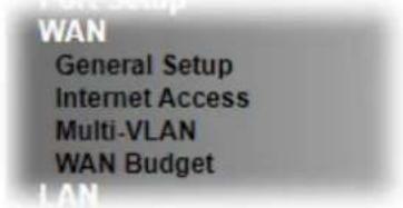
II-2-1 General Setup
This section will introduce some general settings of Internet and explain the connection modes for WAN1\~WAN8 in details.
This router supports multiple-WAN function. It allows users to access Internet and combine the bandwidth of the multiple WANs to speed up the transmission through the network. Each WAN port can connect to different ISPs, Even if the ISPs use different technology to provide telecommunication service (such as DSL, Cable modem, etc.). If any connection problem occurred on one of the ISP connections, all the traffic will be guided and switched to the normal communication port for proper operation. Please configure WAN# settings.
This webpage allows you to set general setup for WAN# respectively.
WAN >> General Setup
| Index | Enable | Physical Mode/Type | Bandwidth(Kbps) DownLink/UpLink | Latency | Jitter | Pkt.Loss | Active Mode | Load Balance |
| WAN1 | √ | Fiber/Auto negotiation / P1 | - / - | - | - | - | Always On | √ |
| WAN3 | √ | Ethernet/Auto negotiation / P3 | 4 / 28 | 18.2 ms | 1.8 ms | 0% | Always On | √ |
| WAN5 | √ | Ethernet/Auto negotiation / P5 | - / - | - | - | - | Always On | √ |
| WAN6 | √ | Ethernet/Auto negotiation / P6 | - / - | - | - | - | Always On | √ |
| WAN7 | √ | Ethernet/Auto negotiation / P7 | - / - | - | - | - | Always On | √ |
| WAN8 | √ | Ethernet/Auto negotiation / P8 | - / - | - | - | - | Always On | √ |
Load Balance Setup Advanced
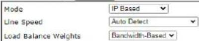
Note:
Latency, jitter, and packet-loss require setting Link Condition Detection in each WAN setting page.
OK Cancel
Available settings are explained as follows:
| Item | Description |
| Index (WAN1 ~WAN8) | Click the WAN interface link under Index to access into the WAN configuration page. |
| Enable Check the box to enable this WAN interface. | |
| Physical Mode / Type | Display the physical mode, physical type, and LAN port of this WAN interface. |
| Line Speed(Kbps)DownLink/UpLink | Display the downstream and upstream rate of this WAN interface. |
| Active Mode Display whether this WAN interface is Active device or backup device.Always On - WAN is always enabled. | |
| Backup (WAN#)- Display the backup WAN interface for this WAN when it is disabled. | |
| Load Balance V means the function of load balance for such WAN interface is enabled. | |
| Load Balance Setup | Advanced- Load Balance for the traffic of STUN, google STUN, and SIP are disabled in default to prevent from conflict. The following dialog allows you to define protocol, port and name for the traffic not to be applied with load balance. That is, when an item is enabled (checked), it might not be affected by load balance.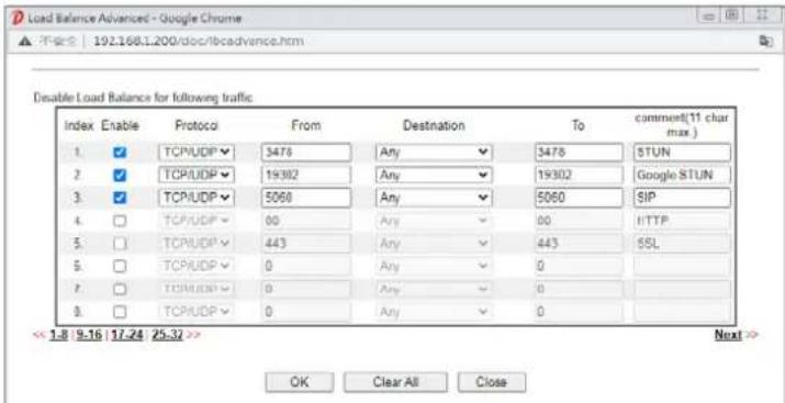 |
| Mode | IP Based - The same source / destination IP pair w the same WAN interface as policy. It is the default setting.Session Based- All of the WAN interfaces will be used (as out-going WAN) for passing through new sessions to get better transmission speed. Though good speed test result for throughput might be reached; however, some web site may not open smoothly, especially the site need authentication, e.g., FTP.If you have no strong demand about speed test result, keep default settings as IP based. |
| Line Speed This option is available for multiple-WAN for getting enough bandwidth for each WAN port. If you know the practical bandwidth for your WAN interface, please choose the setting of According to Line Speed. Otherwise, please choose Auto Detect to let the router reach the best load balance. | |
| Load Balance Weights There are four weight types for choosing to meet your request.Custom- You can distribute the usage ratio for each WAN interface by setting weights for bandwidth, latency, jitter, and packet loss respectively.Load Balance Weights CustomUpload BandwidthWeight: Low Download BandwidthWeight: Low Low LatencyWeight: Low Low JitterWeight: Low Less Packet LossWeight: Low High | |
| ● Upload / Download Bandwidth - The higher the weight is, the WAN interface with higher bandwidth will get higher usage.● Low Latency - It defines the time taken by Vigor router when sending the packets to the IP set in Link Condition Detection. The higher the weight is, the WAN interface with lower latency will get higher usage.● Low Jitter - It defines the change rate of latency. For stable session, small jitter value will be better. The higher the weight is, the WAN interface with lower jitter will get higher usage.● Less Packet Loss - It defines the proportion that packets will be discarded before arriving at the IP set in Link Condition Detection. The higher the weight is, the WAN interface with lower packet loss will get higher usage.Bandwidth-Based - The load balance weight for each WAN will be executed according to line speed setting (DownLink/ UpLink Rate). This is default setting.Quality-Based - The load balance weight for each WAN will be executed according to the transmission rate, latency time and the jitter time.Reliability-Based - The load balance weight for each WAN will be executed according to line speed and packet loss value. Usually, the WAN interface with low packet loss will have the higher ratio to be used. |

Info
In default, each WAN port is enabled.
After finished the above settings, click OK to save the settings.
To configure WAN interface settings, click the WAN# link to open the following page.
WAN 3
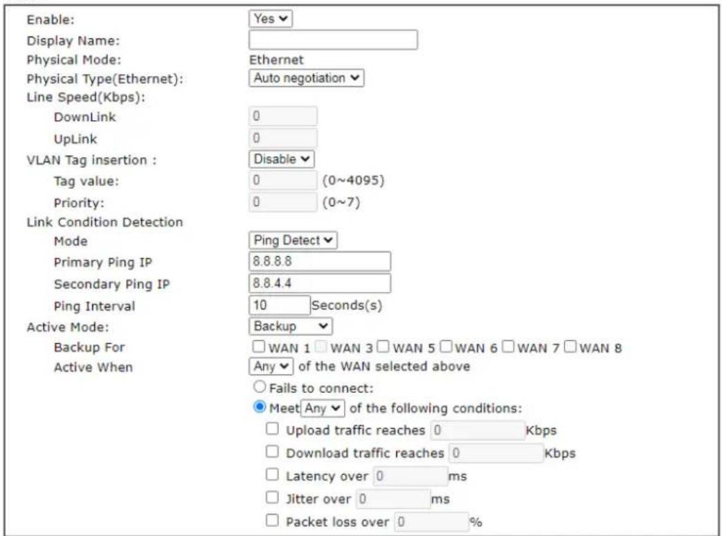
Note:
The line speed setting of WAN interface is available only when According to Line Speed is selected as the Load Balance Mode.

Available settings are explained as follows:
| Item | Description |
| Enable | Choose Yes to invoke the settings for this WAN interface.Choose No to disable the settings for this WAN interface. |
| Display Name Type the description for such WAN interface. | |
| Physical Mode Display the physical mode of such WAN interface. | |
| Physical Type | You can change the physical type for WAN or choose Auto negotiation for determined by the system. |
| Line Speed | If your choose According to Line Speed as the Load Balance Mode, please type the line speed for downloading and uploading for such WAN interface. The unit is kbps. |
| VLAN Tag insertion Such feature is offered to the user with the environment supporting IEEE_802.1ad. In which, service is used for outer tag; customer is used for inner tag.It is available only when Ethernet is selected as Physical Mode.Disable - Disable the function of VLAN with tag.Enable -Enable the function of VLAN with tag.The router will add specific VLAN number to all packets on the WAN while sending them out.Please Enter the tag value and specify the priority for the | |
| packets sending by WAN1.Tag value - Enter the value as the VLAN ID number.The range is form 0 to 4095.Priority - Enter the packet priority number for such VLAN. The range is from 0 to 7. | |
| Link Condition Detection | In order for the system to detect the latency, jitter, and packet-loss status for each WAN interface, you have to specify the IP transmitting data through the interface.Mode - Choose Ping Detect, Http Detect, or Disable as detection mode. If Ping Detect or Http Detect is selected, you have to configure the following option.Primary Ping IP - Enter an IP address.Secondary Ping IP - Enter an IP address.Ping Interval - Set a time interval (unit:second) for the system to ping the IP address specified above. |
| Active Mode | Always On - Choose Always On to make this WAN connection being activated always.Backup - Choose it to make this WAN connection as a backup connection.Backup For - Specify the WAN interface by checking the WAN box. This WAN will be the backup WAN for the selected WAN interface(s).Active When - Set the condition for backup connection.Any/All - This WAN will be activated when any/ all master WAN interface(s),Fails to connectMeet All/Any of the following conditions - When the upload traffic, download traffic, latency, jitter and/ or packet loss of active WAN reaches the traffic threshold (specified here), the backup WAN will be enabled automatically to share the overloaded data traffic. |
After finished the above settings, click OK to save the settings.
II-2-2 Internet Access
For the router supports multi-WAN function, the users can set different WAN settings for Internet Access. Due to different Physical Mode for WAN interface, the Access Mode for these connections also varies. Refer to the following figures.
WAN >> Internet Access
Internet Access
| Index | Display Name | Physical Mode / Port | Access Mode | ||
| WAN1 | SFP+ / P1 | Static or Dynamic IP | Details Page | IPv6 | |
| WAN3 | Ethernet / P3 | PPPoE | Details Page | IPv6 | |
| WAN5 | Ethernet / P5 | Static or Dynamic IP | Details Page | IPv6 | |
| WAN6 | Ethernet / P6 | Static or Dynamic IP | Details Page | IPv6 | |
| WAN7 | Ethernet / P7 | Static or Dynamic IP | Details Page | IPv6 | |
| WAN8 | Ethernet / P8 | Static or Dynamic IP | Details Page | IPv6 | |
DHCP Client Option
Available settings are explained as follows:
| Item | Description |
| Index Display the WAN interface. | |
| Display Name It shows the name of the WAN1 ~ WAN8 that entered in general setup. | |
| Physical Mode / Port It shows the physical connection for WAN(Ethernet) / port number according to the real network connection. | |
| Access Mode Use the drop down list to choose a proper access mode. The details page of that mode will be popped up. If not, click Details Page for accessing the page to configure the settings. | |
| Details Page This button will open different web page (based on IPv4) according to the access mode that you choose in WAN interface.Note that Details Page will be changed slightly based on physical mode. | |
| IPv6 | This button will open different web page (based on Physical Mode) to setup IPv6 Internet Access Mode for WAN interface. If IPv6 service is active on this WAN interface, the color of “IPv6” will become green. |
| DHCP Client Option | This button allows you to configure DHCP client options. DHCP packets can be processed by adding option number and data information when such function is enabled and configured. |
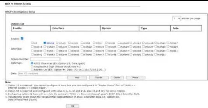
Enable - Check the box to enable the function of DHCP Option. Each DHCP option is composed by an option number with data. For example,
Option number:100
Data: abcd
When such function is enabled, the specified values for DHCP option will be seen in DHCP reply packets.
Interface - Specify the WAN interface(s) that will be overwritten by this function. WAN13 \~ WAN52 can be located under WAN>>Multi-VLAN.
Option Number - Type a number for such function.
DataType - Choose the type (ASCII or Hex) for the data to be stored.
Data - Type the content of the data to be processed by the function of DHCP option.

Info
If you choose to configure option 61 here, the detailed settings in WAN>>Interface Access will be overwritten.
II-2-2-1 Details Page for PPPoE
To choose PPPoE as the accessing protocol of the Internet, please select PPPoE from the WAN>>Internet Access >>WAN3 page. The following web page will be shown.
WAN >> Internet Access
WAN 3
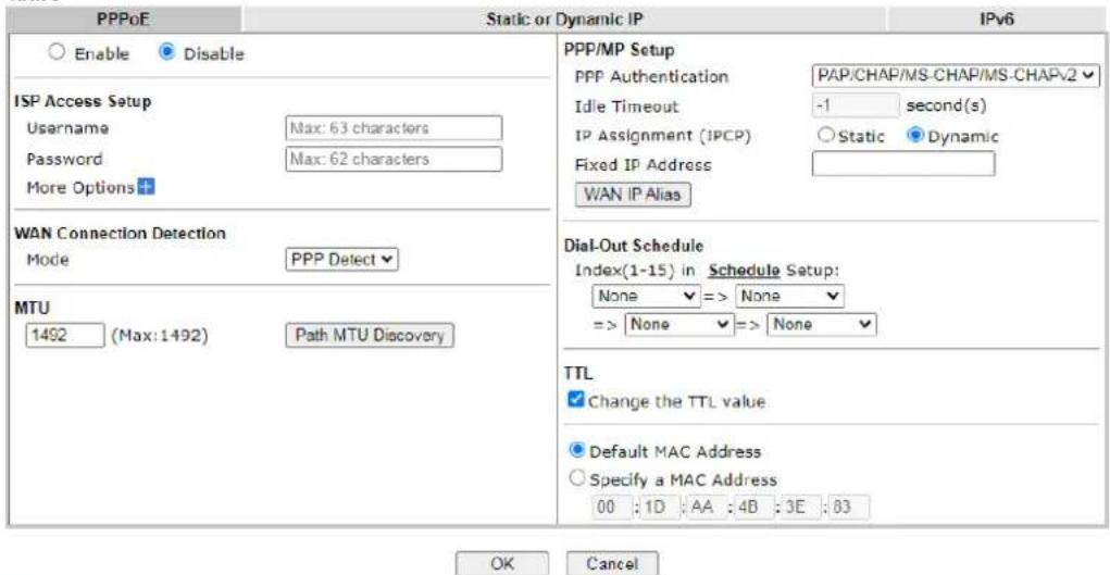
Note:
VPN feature may be affected when the value of MTU is changed, please also check your value of VPN MSS in VPN and Remote Access >> PPP General Setup or VPN and Remote Access >> IPsec General Setup page.
We recommend to put the same decreased value on VPN MSS. For example, reducing the MTU from 1500 -> 1400, then it will need to reduct 100 from MSS value.
Available settings are explained as follows:
| Item | Description |
| Enable/Disable | Enable or disable PPPoE access mode. |
| ISP Access Setup Enter your | allocated username, password and authentication parameters according to the information provided by your ISP.Usage - Username provided by the ISP for PPPoE authentication.Password - Password provided by the ISP for PPPoE authentication.More Options -Service Name (Optional) - Sets the PPP service name tag. Required by some ISPs. Leave blank unless instructed otherwise by your ISP. |
| WAN Connection Detection | Configures how the WAN connection is monitored.Mode - Choose ARP Detect or Ping Detect for the system to execute for WAN detection.ARP Detect - The router broadcasts an ARP request every 5 seconds. If no response is received within 30 seconds, the WAN connection is deemed to have failed.Ping Detect - The router sends an ICMP (Internet Control Message Protocol) echo request every second to the host, whose address is specified in the Ping IP field, to verify the WAN connection. If the remote host does not respond within 30 seconds, the WAN connection is deemed to have failed.If you choose Ping Detect as the detection mode, you have to enter required settings for the following items.Primary/Secondary Ping IP - Enter Primary or Secondary IP address in this field for pinging.Ping Gateway IP - Enable this setting to use current WAN gateway IP address for pinging.With the IP address(es) pinging, Vigor router can check if the WAN connection is on or off.TTL (Time to Live) - Time To Live, the maximum allowed number of hops to the ping destination. Valid values range from 1 to 255.Ping Interval - Enter the interval for the system to execute the PING operation.Ping Retry - Enter the number of times that the system is allowed to execute the PING operation before WAN disconnection is judged. |
| MTU Maximum Transmission | Unit, the size of the largest packet, in bytes, that can be transmitted to the WAN. The maximum value is 1500. For PPPoE connections, there is always an 8-byte overhead, so the maximum valid MTU value for PPPoE is 1492.Path MTU Discovery - Use this feature to determine the optimal MTU size for the WAN.Click Path MTU Discovery to open the following dialog.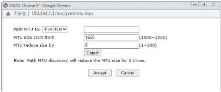 Path MTU to - Select Host / IP, for an IPv4 address or Host / IPv6, for an IPv6 address, and then enter the IP address in the textbox.MTU size start from - Determine the starting point value of the packet.MTU reduce size by - Number of octets by which to decrease the 1500-byte MTU. Start with a 0 value for the reduce size and click the Detect button. If the message Fail is returned, increase the MTU reduce size and try again. Repeat until you see the message Success, indicating that the optimal MTU size has been reached.Detect - Click it to detect a suitable MTU value.Accept - After clicking it, the detected value will be displayed in the field of MTU. Path MTU to - Select Host / IP, for an IPv4 address or Host / IPv6, for an IPv6 address, and then enter the IP address in the textbox.MTU size start from - Determine the starting point value of the packet.MTU reduce size by - Number of octets by which to decrease the 1500-byte MTU. Start with a 0 value for the reduce size and click the Detect button. If the message Fail is returned, increase the MTU reduce size and try again. Repeat until you see the message Success, indicating that the optimal MTU size has been reached.Detect - Click it to detect a suitable MTU value.Accept - After clicking it, the detected value will be displayed in the field of MTU. |
| PPP/MP Setup PPP Authentication | - The protocol used for PPP authentication.PAP only - Only PAP (Password Authentication Protocol) is used.PAP/CHAP/MS-CHAP/MS-CHAPv2 - Both PAP and CHAP (Challenge-Handshake Authentication Protocol) can be used for PPP authentication. Router negotiates with the PPTP or L2TP server to determine which protocol to use.Idle Timeout - Set the timeout for breaking down the Internet after passing through the time without any action.Assignment (IPCP) - Configure the router according to how your ISP allocates WAN IP address(es) to you.Static - ISP has assigned a fixed WAN IP address, which is to be entered below in Fixed IP Address.Dynamic - WAN IP address is dynamically allocated.Fixed IP Address - Enter a fixed IP address.WAN IP Alias - Click to enter multiple WAN IP addresses assigned by your ISP.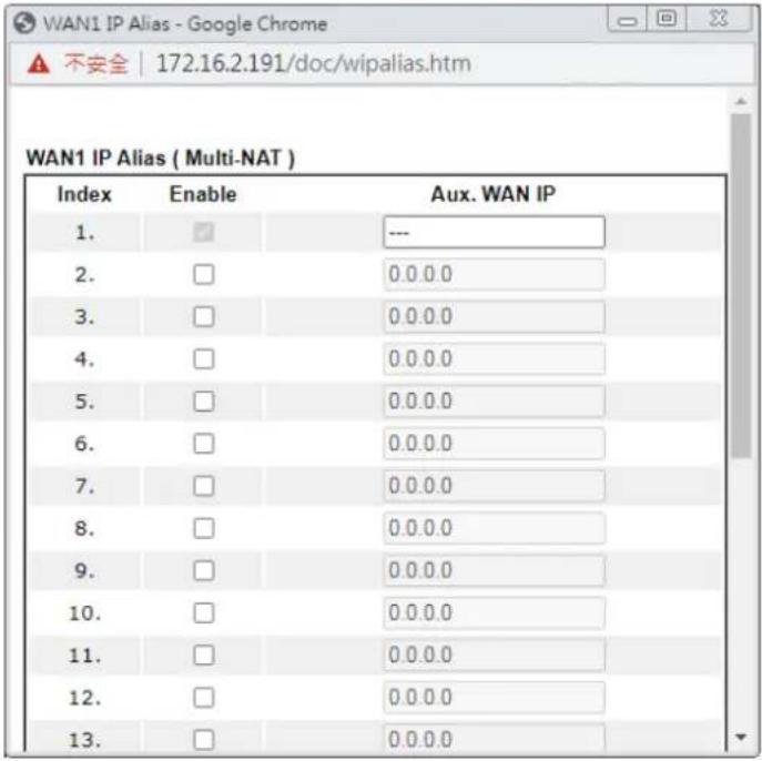 |
| Dial-Out Schedule Specify up to 4 time schedule entries to enable or disable the WAN. All the schedules can be set previously inApplications >> Schedule web page and you can use the number that you have set in that web page. | |
| TTL Change the TTL value - Enable or disable the TTL (Time to Live) for a packet transmitted through Vigor router.If enabled - TTL value will be reduced (-1) when it pass through Vigor router. It will cause the client, accessing Internet through Vigor router, be blocked by certain ISP when TTL value becomes "0".If disabled - TTL value will not be reduced. Then, when a packet passes through Vigor router, it will not be cancelled. That is, the client who sends out the packet will not be blocked by ISP. | |
| MAC Default MAC Address - Use the default MAC address for the WAN Ethernet port.Specify a MAC Address - Specify a MAC address for the WAN | |
| Ethernet port. Select this option if your ISP authenticates by MAC addresses. | |
After finishing all the settings here, please click OK to activate them.
II-2-2-2 Details Page for Static or Dynamic IP
For static IP mode, you usually receive a fixed public IP address or a public subnet, namely multiple public IP addresses from your DSL or Cable ISP service providers. In most cases, a Cable service provider will offer a fixed public IP, while a DSL service provider will offer a public subnet. If you have a public subnet, you could assign an IP address or many IP address to the WAN interface.
To use Static or Dynamic IP as the accessing protocol of the internet, please click the Static or Dynamic IP tab. The following web page will be shown.
WAN >> Internet Access
WAN 3
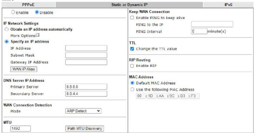
Note:
VPN feature may be affected when the value of MTU is changed, please also check your value of VPN MSS in VPN and Remote Access >> PPP General Setup or VPN and Remote Access >> IPsec General Setup page. We recommend to put the same decreased value on VPN MSS. For example, reducing the MTU from 1500 -> 1400, then it will need to reduct 100 from MSS value.
Available settings are explained as follows:
| Item | Description |
| Enable/Disable | Enable or disable Static or Dynamic IP access mode. |
| IP Network Settings | Obtain an IP address automatically - The router receives IP configuration information from a DHCP server.More Options - Click to set more options.Router Name- Used by some ISPs. Contact your ISP for the appropriate values.Domain Name -Used by some ISPs. Contact your ISP for the appropriate values.Enable DHCP Client Identifier* - Used by some ISPs that authenticates using DHCP Client Identifier (Option 61). To enable, tick this box and fill out theUsernameand Passwordfields below.Specify an IP address -Use the IP address, Subnet Mask andGateway values specified below.IP Address -WAN IP address assigned by the ISP.Subnet Mask -WAN subnet mask.Gateway IP Address - IP address of the WAN Gateway.WAN IP Alias - Click to enter multiple WAN IP addresses assigned by your ISP. |
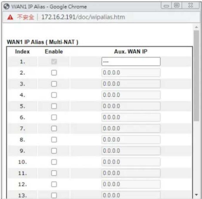 | |
| DNS Server IP Address | Primary IP Address - IP address of primary DNS server.Secondary IP Address - IP address of secondary DNS server. |
| WAN Connection Detection | Configures how the WAN connection is monitored.Mode - Choose ARP Detect, Ping Detect,Always On or Strict ARP Detectfor the system to execute for WAN detection.ARP Detect- The router broadcasts an ARP request every 5 seconds. If no response is received within 30 seconds, the WAN connection is deemed to have failed.Ping Detect- The router sends an ICMP (Internet Control Message Protocol) echo request every second to the host, whose address is specified in the Ping IP field, to verify the WAN connection. If the remote host does not respond within 30 seconds, the WAN connection is deemed to have failed.Always On- The router assumes the WAN connection is always active.If you choose Ping Detectas the detection mode, you have to enter required settings for the following items.Primary/Secondary Ping IP - Enter Primary or Secondary IP address in this field for pinging.Ping Gateway IP - Enable this setting to use current WAN gateway IP address for pinging.With the IP address(es) pinging, Vigor router can checkif the WAN connection is on or off.TTL (Time to Live) - Time To Live, the maximum allowed number of hops to the ping destination. Valid values range from 1 to 255.Ping Interval - Enter the interval for the system to execute the PING operation.Ping Retry - Enter the number of times that the system is allowed to execute the PING operation before WAN disconnection is judged. |
| MTU Maximum Transmission | Unit, the size of the largest packet, in bytes, that can be transmitted to the WAN. The maximum value is 1500. For PPPoE connections, there is always an 8-byte overhead, so the maximum valid MTU value for PPPoE is 1492.Path MTU Discovery - Use this feature to determine the optimal MTU size for the WAN.Click Path MTU Discovery to open the following dialog.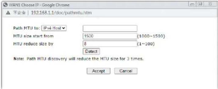 Path MTU to - Select Host / IP, for an IPv4 address or Host / IPv6, for an IPv6 address, and then enter the IP address in the textbox.MTU size start from - Determine the starting point value of the packet.MTU reduce size by - Number of octets by which to decrease the 1500-byte MTU. Start with a 0 value for the reduce size and click the Detect button. If the message Fail is returned, increase the MTU reduce size and try again. Repeat until you see the message Success, indicating that the optimal MTU size has been reached.Detect - Click it to detect a suitable MTU value.Accept - After clicking it, the detected value will be displayed in the field of MTU. Path MTU to - Select Host / IP, for an IPv4 address or Host / IPv6, for an IPv6 address, and then enter the IP address in the textbox.MTU size start from - Determine the starting point value of the packet.MTU reduce size by - Number of octets by which to decrease the 1500-byte MTU. Start with a 0 value for the reduce size and click the Detect button. If the message Fail is returned, increase the MTU reduce size and try again. Repeat until you see the message Success, indicating that the optimal MTU size has been reached.Detect - Click it to detect a suitable MTU value.Accept - After clicking it, the detected value will be displayed in the field of MTU. |
| Keep WAN Connection | Enable PING to keep alive - If selected, ping a WAN host to maintain the connection. If unselected, ping to keep WAN alive is disabled.PING to the IP - IP address of host to be pinged.PING Interval - Number of minutes to wait before sending a ping request to the WAN host. |
| TTL Change the TTL value | - Check the box to enable the TTL(Time to Live) for a packet transmitted through Vigor router.If enabled - TTL value will be reduced (-1) when it passes through Vigor router. It will cause the client, accessing Internet through Vigor router, be blocked by certain ISP when TTL value becomes “0”.● If disabled - TTL value will not be reduced. Then, when a packet passes through Vigor router, it will not be cancelled. That is, the client who sends out the packet will not be blocked by ISP. |
| RIP Routing Routing Information Protocol is abbreviated as RIP(RFC1058).If selected, the router can exchange routing information with other routers. | |
| MAC Address Default MAC Address - Use the default MAC address for the WAN Ethernet port.Specify a MAC Address - Specify a MAC address for the WAN Ethernet port. Select this option if your ISP authenticates by MAC addresses. | |
After finishing all the settings here, please click OK to activate them.
II-2-2-3 Details Page for IPv6 – Offline in Ethernet WAN
When Offline is selected, the IPv6 connection will be disabled.
WAN >> Internet Access

WAN 1
| PPPoE | Static or Dynamic IP | IPv6 |
| Internet Access Mode | ||
| Connection Type | Offline | ✓ |

II-2-2-4 Details Page for IPv6 – PPP
IPv6 WAN address is assigned along with the IPv4 WAN address during PPPoE negotiation. This IPv6 access mode requires that the IPv4 uses PPPoE.
WAN >> Internet Access

WAN 1
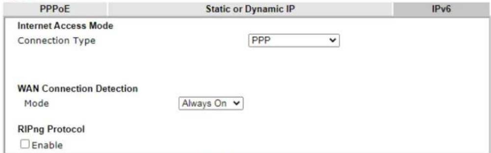
Note: IPv4 WAN setting should be PPPoE / PPPoA client.

Available settings are explained as follows:
| Item | Description |
| WAN Connection Detection | Configures how the WAN connection is monitored. Mode - Choose Ping Detect or Always On for the system to execute for the WAN detection.● Ping Detect - The router sends an ICMP (Internet Control Message Protocol) echo request every second to the host, whose address is specified in the Ping IP field, to verify the WAN connection. If the remote host does not respond within 30 seconds, the WAN connection is deemed to have failed.● Always On - The router assumes the WAN connection is always active.If you choose Ping Detect as the detection mode, you have to enter required settings for the following items.● Ping IP/Hostname - Enter IP address in this field forpinging.●TTL (Time to Live) - Time To Live, the maximum allowed number of hops to the ping destination. Valid values range from 1 to 255. |
| RIPng Protocol RIPng (RIP next generation) offers the same functions and benefits as IPv4 RIP v2. | |
Below shows an example for successful IPv6 connection based on PPP mode.
Online Status
| Physical Connection | System Uptime: 0:2:32 | |||
| IPv4 | IPv6 | |||
| LAN Status | ||||
| IP Address | ||||
| 2001:B010:7300:201:21D:AAFF:FEA6:2568/64 (Global) | ||||
| FE80::21D:AAFF:FEA6:2568/64 (Link) | ||||
| TX Packets | RX Packets | TX Bytes | RX Bytes | |
| 7 | 4 | 690 | 328 | |
| WAN2 IPv6 Status | >> Drop PPP | |||
| Enable | Mode | Up Time | ||
| Yes | PPP | 0:02:08 | ||
| IP | Gateway IP | |||
| 2001:B010:7300:201:21D:AAFF:FEA6:256A/128 (Global) | FE80::90:1A00:242:AD52 | |||
| FE80::1D:AAFF:FEA6:256A/128 (Link) | ||||
| DNS IP | ||||
| 2001:B000:168::1 | ||||
| 2001:B000:168::2 | ||||
| TX Packets | RX Packets | TX Bytes | RX Bytes | |
| 7 | 9 | 544 | 1126 | |

Info
At present, the IPv6 prefix can be acquired via the PPPoE mode connection which is available for the areas such as Taiwan (hinet), the Netherlands, Australia and UK.
II-2-2-5 Details Page for IPv6 – TSPC
Tunnel setup protocol client (TSPC) is an application which could help you to connect to IPv6 network easily.
Please make sure your IPv4 WAN connection is OK and apply one free account from hexago (http://gogonet.gogo6.com/page/freenet6-account) before you try to use TSPC for network connection. TSPC would connect to tunnel broker and requests a tunnel according to the specifications inside the configuration file. It gets a public IPv6 IP address and an IPv6 prefix from the tunnel broker and then monitors the state of the tunnel in background.
After getting the IPv6 prefix and starting router advertisement daemon (RADVD), the PC behind this router can directly connect to IPv6 the Internet.
WAN 1
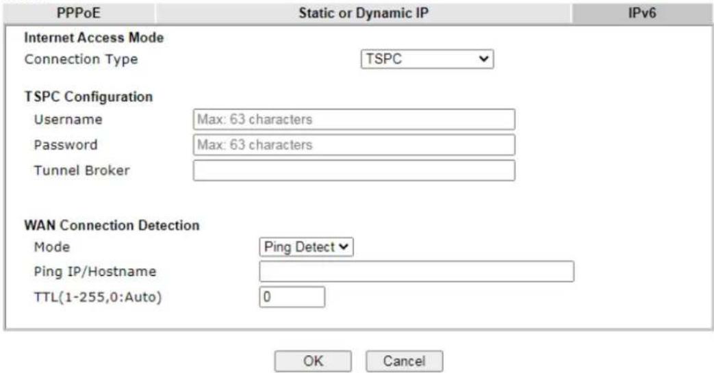
Available settings are explained as follows:
| Item | Description |
| Username Type the name obtained from the broker. It is suggested for you to apply another username and password for http://gogonet.gogo6.com/page/freenet6-account.The maximum length of the name you can set is 63 characters. | |
| Password Enter the password assigned with the user name. | |
| Tunnel Broker | Enter the address for the tunnel broker IP, FQDN or an optional port number. |
| WAN Connection Detection | Configures how the WAN connection is monitored.Mode - Choose Ping Detect or Always On for the system to execute for the WAN detection.Ping Detect - The router sends an ICMP (Internet Control Message Protocol) echo request every second to the host, whose address is specified in the Ping IP field, to verify the WAN connection. If the remote host does not respond within 30 seconds, the WAN connection is deemed to have failed.Always On - The router assumes the WAN connection is always active.If you choose Ping Detect as the detection mode, you have to enter required settings for the following items.Ping IP/Hostname - Enter IP address in this field for pinging.TTL (Time to Live) - Time To Live, the maximum allowed number of hops to the ping destination. Valid values range from 1 to 255. |
After finished the above settings, click OK to save the settings.
II-2-2-6 Details Page for IPv6 – AICCU
WAN >> Internet Access

WAN 1
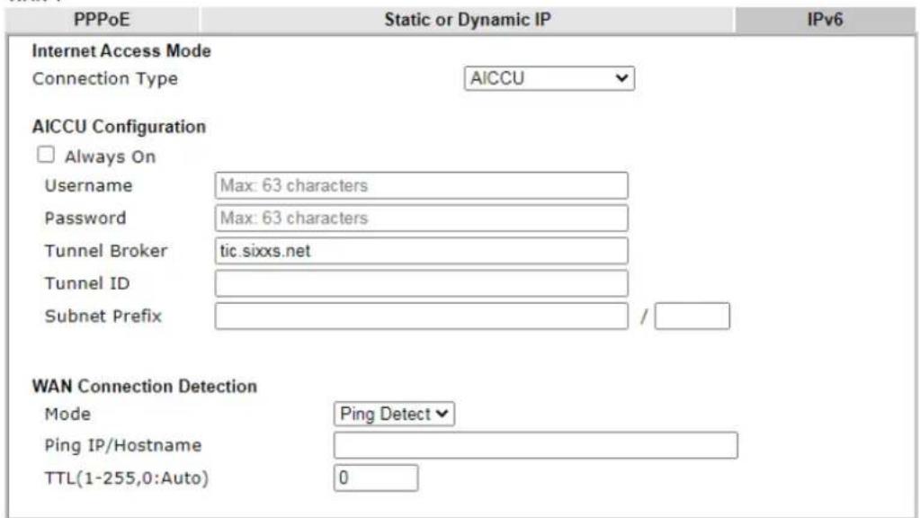
Note: If "Always On" is not enabled, AICCU connection would only retry three times.

Available settings are explained as follows:
| Item | Description |
| Always On | If selected, always attempt to reconnect if connection is lost.If unselected, reconnect up to 3 times if connection is lost. |
| Username Login Username. | Enter the name obtained from the broker. Please apply new account at http://www.sixxs.net/. It is suggested for you to apply another username and password. |
| Password Login Password. | Enter the password. |
| Tunnel Broker Address of the tunnel broker. The server can provide IPv6 tunnels to sites or end users over IPv4.Enter the address for the tunnel broker IP, FQDN or an optional port number. | |
| Tunnel ID One user account | may have several tunnels. And, each tunnel shall have one specified tunnel ID (e.g., T115394).Type the ID offered by Tunnel Broker. |
| Subnet Prefix Type the subnet prefix address obtained from service provider.The maximum length of the prefix you can set is 128 characters. | |
| WAN Connection Detection | Configures how the WAN connection is monitored. Mode - Choose Ping Detect or Always On for the system to execute for the WAN detection.● Ping Detect - The router sends an ICMP (Internet Control Message Protocol) echo request every second to the host, whose address is specified in the Ping IP field, to verify the WAN connection. If the remote host does not respond within 30 seconds, the WAN connection is deemed to have failed.● Always On - The router assumes the WAN connection is always active.If you choose Ping Detect as the detection mode, you have to enter required settings for the following items.● Ping IP/Hostname - Enter an IP address in this field for pinging.● TTL (Time to Live) - Time To Live, the maximum allowed number of hops to the ping destination. Valid values range from 1 to 255. |
After finished the above settings, click OK to save the settings.
II-2-2-7 Details Page for IPv6 – DHCPv6 Client
DHCPv6 client mode would use DHCPv6 protocol to obtain IPv6 address from server.
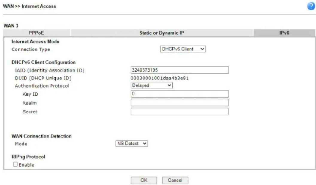
Available settings are explained as follows:
| Item | Description |
| DHCPv6 Client Configuration | IAID - Type a number as IAID.DUID - Display the DHCP unique ID used by such WAN interface.Authentication Protocol - Such protocol will be used for the client to be authenticated by DHCPv6 server before accessing into Internet. There are three types can be specified,Reconfigure Key, Delayed and None. In general, the default setting is None.Reconfigure Key - During the connection process, DHCPv6 server will authenticate the client automatically.Delayed - During the connection process, DHCPv6 server will authenticate and identify the client based on the key ID, realm and secret information specified in these fields.Key ID - Type a value (range from 1 to 65535) which will be used to generate HMAC-MD5 value.Realm - The name (1 to 31 characters) typed here will identify the key which generates HMAC-MD5 value.Secret - Type a text (1 to 31 characters) as s a unique identifier for each client on each DHCP server. |
| WAN Connection Detection | Configures how the WAN connection is monitored.Mode - Choose Always On, Ping Detect or NS Detect for the system to execute for WAN detection.Ping Detect - The router sends an ICMP (Internet Control Message Protocol) echo request every second to the host, whose address is specified in the Ping IP field, to verify the WAN connection. If the remote host does not respond within 30 seconds, the WAN connection isdeemed to have failed.● Always On - The router assumes the WAN connection is always active.● NS Detect - The router verifies connectivity by issuing Neighbor Solicitation packets.If you choose Ping Detect as the detection mode, you have to enter required settings for the following items.● Ping IP/Hostname - Enter an IP address in this field for pinging.● TTL (Time to Live) -Time To Live, the maximum allowed number of hops to the ping destination. Valid values range from 1 to 255. |
| RIPng Protocol RIPng (RIP next generation) offers the same functions and benefits as IPv4 RIP v2. | |
After finished the above settings, click OK to save the settings.
II-2-2-8 Details Page for IPv6 – Static IPv6
This type allows you to setup static IPv6 address for WAN interface.
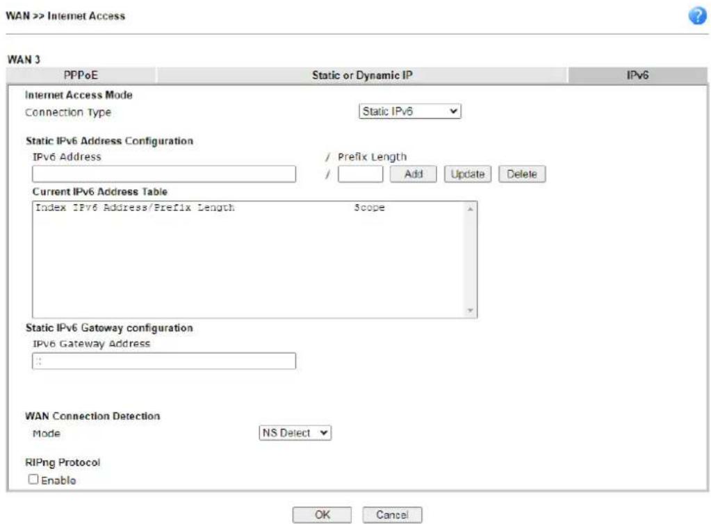
Available settings are explained as follows:
| Item | Description |
| Static IPv6 Address Configuration | IPv6 Address - WAN IPv6 address assigned by the ISPPrefix Length - Length of the IPv6 prefix.Add - Click this button to add the values in the IPv6 Address and Prefix Length fields to the IPv6 address table.Update - Click it to modify an existed entry.Delete - To remove an IPv6 address, select it by clicking onthe entry in the Current IPv6 Address Table, then click the Delete button. |
| Current IPv6 Address Table | Display current interface IPv6 address. |
| Static IPv6 Gateway Configuration | IPv6 Gateway Address - IPv6 address of the ISP gateway. |
| WAN Connection Detection | Configures how the WAN connection is monitored.Mode - Choose Always On, Ping Detect or NS Detect for the system to execute for WAN detection.Ping Detect - The router sends an ICMP (Internet Control Message Protocol) echo request every second to the host, whose address is specified in the Ping IP field, to verify the WAN connection. If the remote host does not respond within 30 seconds, the WAN connection is deemed to have failed.Always On - The router assumes the WAN connection is always active.NS Detect - The router verifies connectivity by issuing Neighbor Solicitation packets.If you choose Ping Detect as the detection mode, you have to enter required settings for the following items.Ping IP/Hostname - Enter an IP address in this field for pinging.TTL (Time to Live) -Time To Live, the maximum allowed number of hops to the ping destination. Valid values range from 1 to 255. |
| RIPng Protocol RIPng (RIP next generation) offers the same functions and benefits as IPv4 RIP v2. | |
After finished the above settings, click OK to save the settings.
II-2-2-9 Details Page for IPv6 – 6in4 Static Tunnel
This type allows you to setup 6in4 Static Tunnel for WAN interface.
Such mode allows the router to access IPv6 network through IPv4 network.
However, 6in4 offers a prefix outside of 2002::0/16. So, you can use a fixed endpoint rather than anycast endpoint. The mode has more reliability.
WAN 1
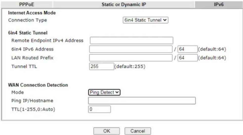
Available settings are explained as follows:
| Item | Description |
| 6in4 Static Tunnel | Remote Endpoint IPv4 Address - WAN IPv6 address assigned by the tunnel provider.6in4 IPv6 Address - WAN IPv6 address and prefix length assigned by the tunnel provider.LAN Routed Prefix - LAN IPv6 address prefix and prefix length.Tunnel TTL - Time to live value, which is the maximum number of hops allowed to the endpoint. |
| WAN Connection Detection | Configures how the WAN connection is monitored.Mode - Choose Always On or Ping Detect for the system to execute for WAN detection.Ping Detect - The router sends an ICMP (Internet Control Message Protocol) echo request every second to the host, whose address is specified in the Ping IP field, to verify the WAN connection. If the remote host does not respond within 30 seconds, the WAN connection is deemed to have failed.Always On - The router assumes the WAN connection is always active.If you choose Ping Detect as the detection mode, you have to enter required settings for the following items.Ping IP/Hostname - Enter an IP address in this field for pinging.TTL (Time to Live) -Time To Live, the maximum allowed number of hops to the ping destination. Valid values range from 1 to 255. |
After finished the above settings, click OK to save the settings.
Below shows an example for successful IPv6 connection based on 6in4 Static Tunnel mode.
Online Status
| Physical Connection | System Uptime: 0day 0:4:16 | |||
| IPv4 | IPv6 | |||
| LAN Status | ||||
| IP Address | ||||
| 2001:4DD0:FF00:83E4:21D:AAFF:FE83:11B4/64 (Global) | ||||
| FE80::21D:AAFF:FE83:11B4/64 (Link) | ||||
| TX Packets | RX Packets | TX Bytes | RX Bytes | |
| 14 | 80 | 1244 | 6815 | |
| WAN1 IPv6 Status | ||||
| Enable | Mode | Up Time | ||
| Yes | 6in4 Static Tunnel | 0:04:07 | ||
| IP | Gateway IP | |||
| 2001:4DD0:FF10:83E4::2131/64 (Global) | --- | |||
| FE80::C0A8:651D/128 (Link) | ||||
| TX Packets | RX Packets | TX Bytes | RX Bytes | |
| 3 | 26 | 211 | 2302 | |
II-2-2-10 Details Page for IPv6 – 6rd
This type allows you to setup 6rd for WAN interface.
WAN >> Internet Access

WAN 1
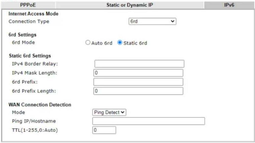

Available settings are explained as follows:
| Item | Description |
| 6rd Settings | Auto 6rd- Used in conjunction with DHCPv4, the router automatically provisions IPv6 using option 212.Static 6rd- IPv6 configuration information is manually entered. |
| Static 6rd Settings IPv4 Border Relay - Enter the IPv4 addresses of the 6rd Border Relay for a given 6rd domain.IPv4 Mask Length - Number of high-order bits that are identical in the IPv4 addresses within the 6rd domain. These bits are excluded when constructing the 6rd delegated prefix.It may be any value between 0 and 32.6rd Prefix - Enter the 6rd IPv6 address.6rd Prefix Length - Enter the IPv6 prefix length for the 6rd IPv6 prefix in number of bits. | |
| WAN Connection Detection | Configures how the WAN connection is monitored.Mode - Choose Always On or Ping Detectfor the system to execute for WAN detection.Ping Detect- The router sends an ICMP (Internet Control Message Protocol) echo request every second to the host, whose address is specified in the Ping IP field, to verify the WAN connection. If the remote host does not respond within 30 seconds, the WAN connection is deemed to have failed.Always On- The router assumes the WAN connection isalways active.If you choose Ping Detect as the detection mode, you have to enter required settings for the following items.Ping IP/Hostname - Enter an IP address in this field for pinging.TTL (Time to Live) -Time To Live, the maximum allowed number of hops to the ping destination. Valid values range from 1 to 255. |
After finished the above settings, click OK to save the settings.
Below shows an example for successful IPv6 connection based on 6rd mode.
Online Status
| Physical Connection | System Uptime: 0day 0:9:15 | |||
| IPv4 | IPv6 | |||
| LAN Status | ||||
| IP Address | ||||
| 2001:E41:A865:1D00:21D:AAFF:FE83:11B4/64 (Global) | ||||
| FE80::21D:AAFF:FE83:11B4/64 (Link) | ||||
| TX Packets | RX Packets | TX Bytes | RX Bytes | |
| 15 | 113 | 1354 | 18040 | |
| WAN1 IPv6 Status | ||||
| Enable | Mode | Up Time | ||
| Yes | 6rd | 0:09:06 | ||
| IP | Gateway IP | |||
| 2001:E41:A865:1D01:21D:AAFF:FE83:11B5/128(Global) | --- | |||
| FE80::C0A8:651D/128 (Link) | ||||
| TX Packets | RX Packets | TX Bytes | RX Bytes | |
| 13 | 29 | 967 | 2620 | |
II-2-3 Multi-VLAN
Multi-VLAN lets you configure multiple VLAN groups.
Channel 1 to 8 have the following fixed assignments and cannot be altered.
Channels 13 through 52 can be configured as virtual WANs.
General
The system allows you to set up to eight channels used as multi-VLAN.
WAN >> Multi-VLAN
Multi-VLAN
| Channel | Display Name | Enable | WAN Type | VLAN Tag | Port-based Bridge |
| 1 | Ethernet(WAN1) | None | |||
| 3 | Ethernet(WAN3) | None | |||
| 5 | Ethernet(WAN5) | None | |||
| 6 | Ethernet(WAN6) | None | |||
| 7 | Ethernet(WAN7) | None | |||
| 8 | Ethernet(WAN8) | None | |||
| 13. WAN13 | Ethernet(WAN1) | None | Enable P2 P4 P9 P10 P11 P12 | ||
| 14. WAN14 | Ethernet(WAN1) | None | Enable P2 P4 P9 P10 P11 P12 | ||
| 15. WAN15 | Ethernet(WAN1) | None | Enable P2 P4 P9 P10 P11 P12 | ||
| 16. WAN16 | Ethernet(WAN1) | None | Enable P2 P4 P9 P10 P11 P12 | ||
| 17. WAN17 | Ethernet(WAN1) | None | Enable P2 P4 P9 P10 P11 P12 | ||
| 18. WAN18 | Ethernet(WAN1) | None | Enable P2 P4 P9 P10 P11 P12 | ||
| 19. WAN19 | Ethernet(WAN1) | None | Enable P2 P4 P9 P10 P11 P12 | ||
| 20. WAN20 | Ethernet(WAN1) | None | Enable P2 P4 P9 P10 P11 P12 | ||
| 21. WAN21 | Ethernet(WAN1) | None | Enable P2 P4 P9 P10 P11 P12 | ||
| 22. WAN22 | Ethernet(WAN1) | None | Enable P2 P4 P9 P10 P11 P12 | ||
| 23. WAN23 | Ethernet(WAN1) | None | Enable P2 P4 P9 P10 P11 P12 | ||
| 24. WAN24 | Ethernet(WAN1) | None | Enable P2 P4 P9 P10 P11 P12 | ||
| 25. WAN25 | Ethernet(WAN1) | None | Enable P2 P4 P9 P10 P11 P12 | ||
| 26. WAN26 | Ethernet(WAN1) | None | Enable P2 P4 P9 P10 P11 P12 | ||
| 27. WAN27 | Ethernet(WAN1) | None | Enable P2 P4 P9 P10 P11 P12 |
Available settings are explained as follows:
| Item | Description |
| Channel Display the number | of each channel.Channels 1~8 are used by the Internet Access web user interface and can not be configured here.Channels 13 ~ 52 are configurable. |
| Enable Display whether the | settings in this channel are enabled (checked) or not (unchecked). |
| WAN Type | Displays the physical medium that the channel will use. |
| VLAN Tag | Displays the VLAN tag value that will be used for the packets traveling on this channel. |
| Port-based Bridge The network | work traffic flowing on each channel will be identified by the system via their VLAN Tags. Channels using the same WAN type may not configure the same VLAN tag value.Enable - Check this box to enable the port-based bridge function on this channel.P2 ~ P12 - Check the box(es) to build bridge connection on LAN. |
Click any index (13\~52) to get the following web page:
WAN >> Multi-VLAN >> Channel 13
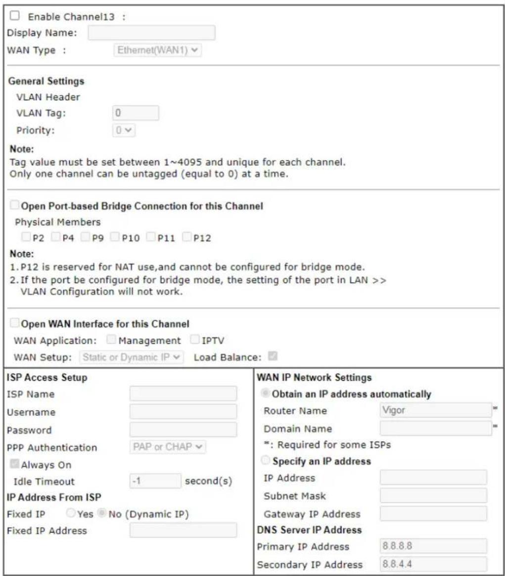

Available settings are explained as follows:
| Item | Description |
| Enable Channel 13~52 | Enable - Click it to enable the configuration of this channel. Disable -Click it to disable the configuration of this channel. |
| WAN Type | The connections and interfaces created in every channel may select a specific WAN type to be built upon. In the Multi-VLAN application, only the Ethernet WAN type is available. The user will be able to select the physical WAN interface the channel shall use here. |
| General Settings VLAN Tag | - Type the value as the VLAN ID number. Valid settings are in the range from 1 to 4095. The network traffic flowing on each channel will be identified by the system viatheir VLAN Tags. Channels using the same WAN type may not configure the same VLAN tag value.Priority- Choose the number to determine the packet priority for such VLAN. The range is from 0 to 7. |
| Open Port-based Bridge Connection for this Channel | If selected, bridge this channel to one or more LAN ports.Physical Members- If selected, a channel is bridged to this LAN port.Note: LAN port P1 is reserved for NAT use and cannot be selected for bridging. |
| Open WAN Interface for this Channel | If selected, NAT (Network Address Translation) will be applied to this channel to create a virtual WAN. The virtual WAN carries the same number as the channel itself.WAN Application- The intended usage of this channel.Management- The router can be managed using the web-based configuration, telnet and TR-069 via this channel.IPTV - IGMP packets can be sent to IPTV servers on this channel.WAN Setup- The WAN access method of this channel.Available options are PPPoE/ PPPoA and Static or Dynamic IP.PPPoE/PPPoA- When PPPoE/ PPPoA is selected, the ISP Access Setup and IP Address From ISP settings are available for configuration, and will be used to establish the WAN connection.Static or Dynamic IP- When Static or Dynamic IP is selected, the WAN IP Network Settings and DNS Server IP Address settings are available for configuration, and will be used to establish the WAN connection. |
| ISP Access Setup Enter your | allocated username, password and authentication parameters according to the information provided by your ISP.Usage- Name provided by the ISP for PPPoE/ PPPoA authentication. Maximum length is 62 characters.Password- Password provided by the ISP for PPPoE/ PPPoA authentication. Maximum length is 62 characters.PPP Authentication-The protocol used for PPP authentication.PAP only- Only PAP (Password Authentication Protocol) is used.PAP or CHAP- Both PAP and CHAP (Challenge-Handshake Authentication Protocol) can be used for PPP authentication. Router negotiates with the PPTP or L2TP server to determine which protocol to use.Always On- If selected, the router will maintain the PPPoE/ PPPoA connection.Idle Timeout- Maximum length of time, in seconds, of idling allowed (no traffic) before the connection is dropped.IP Address from ISP- Specifies how the WAN IP address of the channel configured.Fixed IPYes- IP address entered in the Fixed IP Address field will be used as the IP address of the virtual WAN.No- Virtual WAN IP address will be assigned by the ISP's PPPoE/ PPPoA server.● Fixed IP Adders - Enter an IP address. |
| WAN IP Network Settings | Obtain an IP address automatically – Select this option if the router is to receive IP configuration information from a DHCP server.● Router Name – Sets the value of DHCP Option 12, which is used by some ISPs.● Domain Name – Sets the value of DHCP Option 15, which is used by some ISPs.Specify an IP address – Select this option to manually enter the IP address.● IP Address – Enter the IP address.● Subnet Mask – Enter the subnet mask.● Gateway IP Address – Enter gateway IP address.DNS Server IP Address - Enter the primary IP address for the router if you want to use Static IP mode. If necessary, Enter secondary IP address for necessity in the future. |
After finished the above settings, click OK to save the settings and return to previous page.
II-2-4 WAN Budget
This function is used to determine the data traffic volume for each WAN interface respectively to prevent overcharges for data transmission by the ISP. Please note that the Quota Limit and Billing cycle day of month settings will need to be configured correctly first in order for some period calculations to be performed correctly.
The WAN Budget feature allows you to conveniently keep track of Internet traffic volume. You can:
- set up calendar cycles to monitor;
- limit your Internet usage according to your ISP's quota;
- set up action(s) to take when the quota is exceeded.
II-2-4-1 General Setup
WAN >> WAN Budget
| General Setup | Status | ||||
| Index | Enable | Quota | When quota exceeded | Time cycle | Duration |
| WAN1 | 0MB/0MB | 0/00/00 00:00~0/00/00 00:00 | |||
| WAN2 | 0MB/0MB | 0/00/00 00:00~0/00/00 00:00 | |||
| WAN3 | 0MB/0MB | 0/00/00 00:00~0/00/00 00:00 | |||
| WAN4 | 0MB/0MB | 0/00/00 00:00~0/00/00 00:00 | |||
| WAN5 | 0MB/0MB | 0/00/00 00:00~0/00/00 00:00 | |||
| WAN6 | 0MB/0MB | 0/00/00 00:00~0/00/00 00:00 | |||
| WAN7 | 0MB/0MB | 0/00/00 00:00~0/00/00 00:00 | |||
| WAN8 | 0MB/0MB | 0/00/00 00:00~0/00/00 00:00 | |||
Note:
-
The budget traffic information provided here is for reference only, please consult your ISP for the actual traffic usage and charges.
-
When hardware acceleration function is used, the monitored WAN traffic of Ethernet WAN interfaces may be slightly inaccurate.

| Item | Description |
| Index The WAN port. | Click to configure WAN Budget for a particular WAN. |
| Enable | v - WAN Budget is enabled on this WAN.x - WAN Budget is disabled on this WAN. |
| Quota | The current cycle's Internet usage is expressed as x/y where x is the cumulative usage and y is the upper limit. For example, 100MB/200MB means the usage thus far in this cycle is 100MB, and the upper limit is 200MB. |
| When quota exceeded Actions to be taken once the quota is reached.Shutdown - WAN will be disabled.Mail Alert - Email will be sent to the administrator. | |
| Time cycle Reset frequency of the usage data.Monthly - The Monthly option in the Criterion and Action tab was used to set up the usage quota.User Defined: The User Defined option in the Criterion and Action tab was used to set up the usage qota. | |
Duration Start and end timestamps of the current cycle.
Click WAN1 (to WAN8) link to open the following web page.
WAN >> WAN Budget
WAN 1
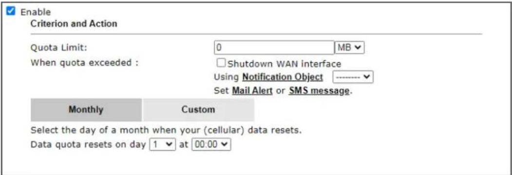
Note:
- Please make sure the Time and Date of the router is configured.
- SMS message and mail will be sent when the usage reaches 95% and 100% of quota.
OK
Cancel
Available settings are explained as follows:
| Item | Description |
| Enable When selected, WAN | Budget is enabled for this WAN. |
| Quota Limit Enter the data | traffic quota allowed for such WAN interface.There are two unit (MB and GB) offered for you to specify. |
| When quota exceeded Check the box(es) as the condition(s) for the system to perform when the traffic has exceeded the budget limit.Shutdown WAN interface - All the outgoing traffic through such WAN interface will be terminated.Using Notification Object - The system will send out a notification based on the content of the notification object.Set Mail Alert - The system will send out a warning message to the administrator when the quota is running out. However, the connection charges will be calculated continuously.Set SMS message - The system will send out SMS message to the administrator when the quota is running out. | |
| Monthly Some ISP might apply for the network limitation based on the traffic limit per month. This setting is to offer a mechanism of resetting the traffic record every month.Monthly CustomSelect the day of a month when your (cellular) data resets.Data quota resets on day 1 at 00:00Data quota resets on day ... - You can determine the starting day in one month. | |
| Custom | This setting allows the user to define the billing cycle according to his request. The WAN budget will be reset with |
an interval of billing cycle.
Monthly is default setting. If long period or a short period is required, use Custom. The period of cycle duration is between 1 day and 60 days. You can determine the cycle duration by specifying the days and the hours. In addition, you can specify which day of today is in a cycle.
Use Cycle in hours -
Monthly
Custom
Use Cycle in hours
○ Use Cycle in days
Usage counter resets at the beginning of each cycle.
Cycle duration : 1 ▼ days and 0 ▼ hours
Today is day 1 √ in the cycle.
- Cycle duration: Specify the days and hours to reset the traffic record. For example, 7 means the whole cycle is 7 days; 20 means the whole cycle is 20 days. When the time is up, the router will reset the traffic record automatically.
- Today is day – Specify the day in the cycle as the starting point which Vigor router will reset the traffic record. For example, “3” means the third day of the cycle duration.
Use Cycle in days -
Monthly
Custom
○ Use Cycle in hours
Use Cycle in days
Usage counter resets at the beginning of each cycle.
Cycle duration : 1 √ days.
Today is day 1 in the cycle and data quota resets at 00:00
- Cycle duration: Specify the days to reset the traffic record. For example, 7 means the whole cycle is 7 days; 20 means the whole cycle is 20 days. When the time is up, the router will reset the traffic record automatically.
- Today is day - Specify the day and time for data quota rest in the cycle as the starting point which Vigor router will reset the traffic record. For example, "3" means the third day of the cycle duration.
After finished the above settings, click OK to save the settings.
II-2-4-2 Status
The status page displays the status WAN budget, including the duration and the usage.
WAN >> WAN Budget
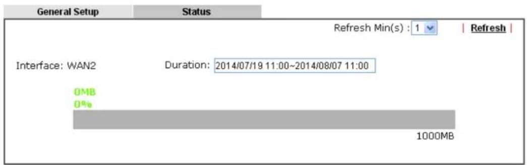
If the WAN budget is exhausted, a lock will be displayed on the page if Shutdown WAN interface is selected. Which means no data transmission will be carried out. Moreover, the system will send out a warning message to the administrator if Mail Alert is selected. Or, the system will send out SMS message to the administrator if SMS message is selected.
WAN >> WAN Budget
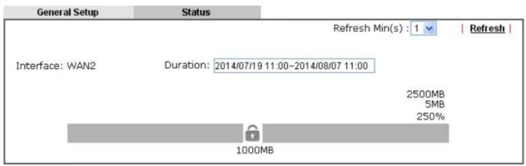
II-3 LAN
A LAN(Local Area Network) comprises a collection of LAN clients, which are networked devices on your premises. A LAN client can be a computer, a printer, a Voice-over-IP (VoIP) phone, a mobile phone, a gaming console, an Internet Protocol Television (IPTV), etc, and can have either a wired (using Ethernet cabling) or wireless (using Wi-Fi) network connection.
LAN clients within the same LAN are normally able to communicate with one another directly, as they are peers to one another, unless measures, such as firewalls or VLANs, have been put in place to restrict such access. Nowadays the most common LAN firewalls are implemented on the LAN client itself. For example, Microsoft Windows since Windows XP and Apple OS X have built-in firewalls that can be configured to restrict traffic coming in and going out of the computer. VLANs, on the other hand, are usually set up using network switches or routers.
To communicate with the hosts outside of the LAN, LAN clients have to go through a network gateway, which in most cases is a router that sits between the LAN and the ISP network, which is the WAN. The router acts as a director to ensure traffic between the LAN and the WAN reach their intended destinations.
IP Address
On most broadband networks, the ISP assigns a single WAN IP address to the subscriber. All LAN clients have to share this WAN IP address when accessing the Internet. To achieve this, a technique called Network Address Translation (NAT) is used. Under NAT, a private block of IP addresses is assigned to the LAN clients, which communicate with WAN hosts through the router, also known as the gateway.
On outgoing traffic to the WAN, the router makes note that a LAN client has attempted to reach a WAN host, and forwards the request to the intended WAN recipient.
On traffic incoming to the LAN from a WAN host, the router checks its records to see if a matching outstanding request from a LAN client to this WAN host exists, and if so, forwards it to the LAN client. Otherwise, the traffic is dropped.
There are 3 distinct blocks of IPv4 address that are reserved for use as private IP addresses on a LAN.
| Name | IP Address | Number of Available Addresses | Largest Subnet Mask |
| 24-bit Block | 1 | 0.0.0.0 to 10.255.255.255 | 16,777,216 |
| 20-bit Block | 1 | 72.16.0.0 to 172.31.255.255 | 1,048,576 |
| 16-bit Block | 1 | 92.168.0.0 to 192.168.255.255 | 65,536 |
The default beginning IP Address of LAN 1 is 192.168.1.1, and the Subnet Mask is 255.255.255.0, for a total of 254 assignable IP addresses, from 192.168.1.1 to 192.168.1.254. The final IP address of the selected range is reserved for routing and cannot be assigned to a LAN client.
In most cases, the default IP address block should work satisfactorily. However, there are situations where you need to select a different address block, such as when you need to communicate with other LANs that already use the same address block.
Private IP addresses can be assigned automatically to LAN clients using Dynamic Host Configuration Protocol (DHCP), or manually assigned. The DHCP server can either be the router (the most common case), or a separate server, that hands out IP addresses to DHCP clients.
Alternatively, static IP addresses can be manually configured on LAN clients as part of their network settings. No matter how IP addresses are configured, it is important that no two devices get the same IP address. If both DHCP and static assignment are used on a network, it is important to exclude the static IP addresses from the DHCP IP pool. For example, if your LAN uses the 192.168.1.x subnet and you have 20 DHCP clients and 20 static IP clients, you could configure 192.168.1.10 as the Start IP Address, 50 as the IP Pool Counts (enough for the current number of DHCP clients, plus room for future expansion), and use addresses greater than 192.168.1.100 for static assignment.
Web User Interface
To begin configuring the LAN settings, select LAN>>General Settings from the menu bar of the Web UI.
LAN
General Setup
VLAN
Bind IP to MAC
Port Mirror/Packet Capture
Wired 802.1X
PPPoE Server
Hot corn/Coal/Diesel
II-3-1 General Setup
This page provides you the general settings for LAN. Click LAN to open the LAN settings page and choose General Setup.
There are several subnets provided by the router which allow users to divide groups into different subnets (LAN2 - LAN100). In addition, different subnets can link for each other by configuring Inter-LAN Routing. At present, LAN1 setting is fixed with NAT mode only. LAN2 - LAN50 can be operated under NAT or Route mode. IP Routed Subnet can be operated under Route mode.
LAN 1 is always enabled and is used as the default subnet. LANs 2 to 100 are subnets to be used in conjunction with Virtual LANs (VLANs). Each VLAN can be configured to allow or disallow communication with other VLANs using the Inter-LAN Routing matrix.
To configure a subnet, select its Details Page button to bring up the LAN Details Page.
LAN >> General Setup
General Setup
| Index | Description | Enable | DHCP | IP Address | ||
| LAN 1 | 3910_Carrie | V | - | 192.168.1.100 | Details Page | IPv6 |
| IP Routed Subnet | ☐ | ☐ | 192.168.0.1 | Details Page | ||
DHCP Server Option
Note:
- Please enable LAN 2 - 100 on LAN >> VLAN page before configure them.
☐ Force router to use "DNS server IP address" settings specified in LAN1
Inter-LAN Routing
| Subnet | LAN 1 | LAN 2 | LAN 3 | LAN 4 | LAN 5 | LAN 6 | LAN 7 | LAN 8 | LAN 9 | LAN 10 | LAN 11 | LAN 12 | LAN 13 | LAN 14 | LAN 15 | LAN 16 | LAN 17 | LAN 18 |
| LAN1 | ||||||||||||||||||
| LAN2 | ||||||||||||||||||
| LAN3 | ||||||||||||||||||
| LAN4 | ||||||||||||||||||
| LAN5 | ||||||||||||||||||
| LAN6 |
OK
Available settings are explained as follows:
| Item | Description |
| General Setup | Allow to configure settings for each subnet respectively.Index - Display all of the LAN items.Enable - Basically, LAN1 status is enabled in default. LAN2 -LAN50 and IP Routed Subnet can be configured after enabling via LAN>>VLAN.DHCP- LAN1 is configured with DHCP in default. If required, please check the DHCP box for each LAN.IP Address - Display the IP address for each LAN item. Such information is set in default and you can not modify it.Details Page - Click it to access into the setting page. Each LAN will have different LAN configuration page. Each LAN must be configured in different subnet.IPv6 - Click it to access into the settings page of IPv6. |
| DHCP Server Options DHCP | packets can be processed by adding option number and data information when such function is enabled.For detailed information, refer to later section. |
| Force router to use “DNS Server IP address”... | Force Vigor router to use DNS servers configured in LAN port instead of DNS servers given by the Internet Access server (PPPoE, PPTP, L2TP or DHCP server). |
| Inter-LAN Routing Check the | box to link two or more different subnets (LAN and LAN).Inter-LAN Routing allows different LAN subnets to be interconnected or isolated.It is only available when the VLAN functionality is enabled.Refer to section II-3-2 VLAN on how to set up VLANs.In the Inter-LAN Routing matrix, a selected checkbox means that the 2 intersecting LANs can communicate with each other. |
When you finish the configuration, please click OK to save and exit this page.

Info
To configure a subnet, select its Detials Page button to bring up the LAN Details Page.
II-3-1-1 Details Page for LAN1 – Ethernet TCP/IP and DHCP Setup
This page has two tabs, LAN Ethernet TCP/IP and DHCP Setup, which sets up the IPv4 LAN environment, and LAN IPv6 Setup, which sets up the IPv6 environment.
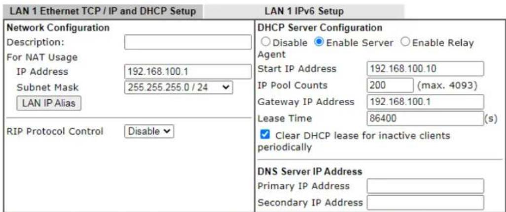
Note: Change IP Address or Subnet Mask in Network Configuration will also change HA LAN1 Virtual IP to the same domain IP.
OK
Available settings are explained as follows:
| Item | Description | ||
| Network Configuration For | NAT Usage,IP Address- This is the IP address of the router. (Default: 192.168.1.1).Subnet Mask- The subnet mask, together with the IP Address field, indicates the maximum number of clients allowed on the subnet. (Default: 255.255.255.0/ 24).LAN IP Alias-Such feature allows specifying multiple gateways (under a switch) with different WAN interfaces for accessing the Internet via the Vigor router. | ||
| LAN 1 IP Alias - Google Chrome不安全 | 192.168.1.1/doc/lanipalias.htm | |||
| LAN 1 IP AliasIndex Enable LAN IP Output Interface1. □ None √2. □ None √3. □ None √4. □ None √5. □ None √Note:1. LAN IP Alias only applies to muti-gateway usage. When a LAN host set its gateway as LAN IP Alias, Vigor Router will route the host's packets through the specified Output Interface.2. Route Policy has a higher priority than the LAN IP Alias Output Interface setting.OK Clear All Cancel | |||
| RIP Protocol Control,Enable -When Enabled, the router will attempt to exchange | |||
| routing information with neighbouring routers using the Routing Information Protocol. | |||
| DHCP Server Configuration | DHCP stands for Dynamic Host Configuration Protocol. The router by factory default acts a DHCP server for your network so it automatically dispatches related IP settings to any local user configured as a DHCP client. It is highly recommended that you leave the router enabled as a DHCP server if you do not have a DHCP server for your network.If you want to use another DHCP server in the network other than the Vigor Router's, you can let Relay Agent help you to redirect the DHCP request to the specified location.Disable- Disables the built-in DHCP server on the router.Enable Server- Enables the built-in DHCP server on the router.Start IP Address- The beginning LAN IP address that is given out to LAN DHCP clients.IP Pool Counts- The maximum number of IP addresses to be handed out by DHCP. The default value is 200. Valid range is between 1 and 1021. The actual number of IP addresses available for assignment is the IP Pool Counts, or 1021 minus the last octet of the Start IP Address, whichever is smaller.Gateway IP Address- The IP address of the gateway, which is the host on the LAN that relays all traffic coming into and going out of the LAN. The gateway is normally the router, and therefore the Gateway IP Address should be identical to the IP Address in the Network Configurationsection above.Lease Time- The maximum duration DHCP-issued IP addresses can be used before they have to be renewed.Clear DHCP lease for inactive clients periodically- If selected, the router sends ARP requests recycles IP addresses previously assigned to inactive DHCP clients to prevent exhaustion of the IP address pool.Note:When Clear DHCP lease for inactive clients periodically is enabled, router will do the following:Check activities of DHCP clients by ARP requests every minute when the available DHCP IP addresses are less than 30Clear DHCP lease when the client is not responding ARP replies.Enable Relay Agent- When selected, all DHCP requests are forwarded to a DHCP server outside of the LAN subnet, and whose address is specified in the DHCP Server IP Address field.DHCP Server IP Address- IP Address of the DHCP server to which DHCP requests from LAN clients are forwarded. | ||
| DNS Server IP Address DNS | stands for Domain Name System. Every Internet host must have a unique IP address, also they may have a human-friendly, easy to remember name such as www.yahoo.com. The DNS server converts the user-friendly name into its equivalent IP address.When these fields are populated, they will be used as the IP addresses of the DNS server information in DHCPv6 responses, overriding the ISP-supplied DNS server addresses. | ||
| Primary IP Address -You must specify a DNS server IP address here because your ISP should provide you with usually more than one DNS Server.Secondary IP Address - You can specify secondary DNS server IP address here because your ISP often provides you more than one DNS Server.The default DNS Server IP address can be found via Online Status:Online Status | |||
| Physical Connection | System Uptime: 22:22:45 | ||
| IPv4 | IPv6 | ||
| LAN Status | Primary DNS: 8.8.8.8 | Secondary DNS: 8.8.4.4 | |
| IP Address | TX Packets | RX Packets | |
| 192.168.1.1 | 0 | 41533 | |
| If both the Primary IP and Secondary IP Address fields are left empty, the router will assign its own IP address to local users as a DNS proxy server and maintain a DNS cache.If the IP address of a domain name is already in the DNS cache, the router will resolve the domain name immediately. Otherwise, the router forwards the DNS query packet to the external DNS server by establishing a WAN (e.g. DSL/Cable) connection. | |||
| Physical Connection | System Uptime: 22:22:45 | ||
| IPv4 | IPv6 | ||
| LAN Status | Primary DNS: 8.8.8.8 | Secondary DNS: 8.8.4.4 | |
| IP Address | TX Packets | RX Packets | |
| 192.168.1.1 | 0 | 41533 | |
When you finish the configuration, please click OK to save and exit this page.
II-3-1-2 Details Page for IP Routed Subnet
LAN >> General Setup
TCP/IP and DHCP Setup for IP Routed Subnet
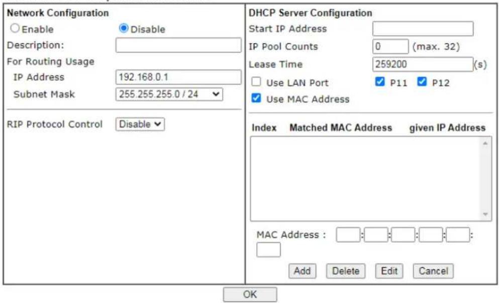
Available settings are explained as follows:
| Item | Description |
| Network Configuration | Enable/Disable - Click Enable to enable such configuration; click Disable to disable such configuration.For Routing Usage,IP Address - This is the IP address of the router. (Default: 192.168.1.1).Subnet Mask - The subnet mask, together with the IP Address field, indicates the maximum number of clients allowed on the subnet. (Default: 255.255.255.0/ 24).RIP Protocol Control,Enable - When Enabled, the router will attempt to exchange routing information with neighbouring routers using the Routing Information Protocol. |
| DHCP Server Configuration | DHCP stands for Dynamic Host Configuration Protocol. The router by factory default acts a DHCP server for your network so it automatically dispatch related IP settings to any local user configured as a DHCP client. It is highly recommended that you leave the router enabled as a DHCP server if you do not have a DHCP server for your network.Start IP Address - Enter a value of the IP address pool for the DHCP server to start with when issuing IP addresses. If the 1st IP address of your router is 192.168.1.1, the starting IP address must be 192.168.1.2 or greater, but smaller than 192.168.1.254.IP Pool Counts - Enter the maximum number of PCs that you want the DHCP server to assign IP addresses to. The default is 50 and the maximum is 253.Lease Time - Enter the time to determine how long the IP address assigned by DHCP server can be used.Use LAN Port - Specify an IP for IP Route Subnet. If it is enabled, DHCP server will assign IP address automatically for the clients coming from P11 and/ or P12. Please check the box of P11 and P12.Use MAC Address - Check such box to specify MAC address.MAC Address: Enter the MAC Address of the host one by one and click Add to create a list of hosts which can be assigned, deleted or edited from above pool. Set a list of MAC Address for 2^nd DHCP server will help router to assign the correct IP address of the correct subnet to the correct host. So those hosts in 2^nd subnet won't get an IP address belonging to 1^st subnet.Add - Enter the MAC address in the boxes and click this button to add.Delete - Click it to delete the selected MAC address.Edit - Click it to edit the selected MAC address.Cancel - Click it to cancel the job of adding, deleting and editing. |
When you finish the configuration, please click OK to save and exit this page.
II-3-1-3 Details Page for LAN1 – IPv6 Setup
There are two configuration pages for LAN1, Ethernet TCP/IP and DHCP Setup (based on IPv4) and IPv6 Setup. Click the tab for each type and refer to the following explanations for detailed information. Below shows the settings page for IPv6.
LAN >> General Setup
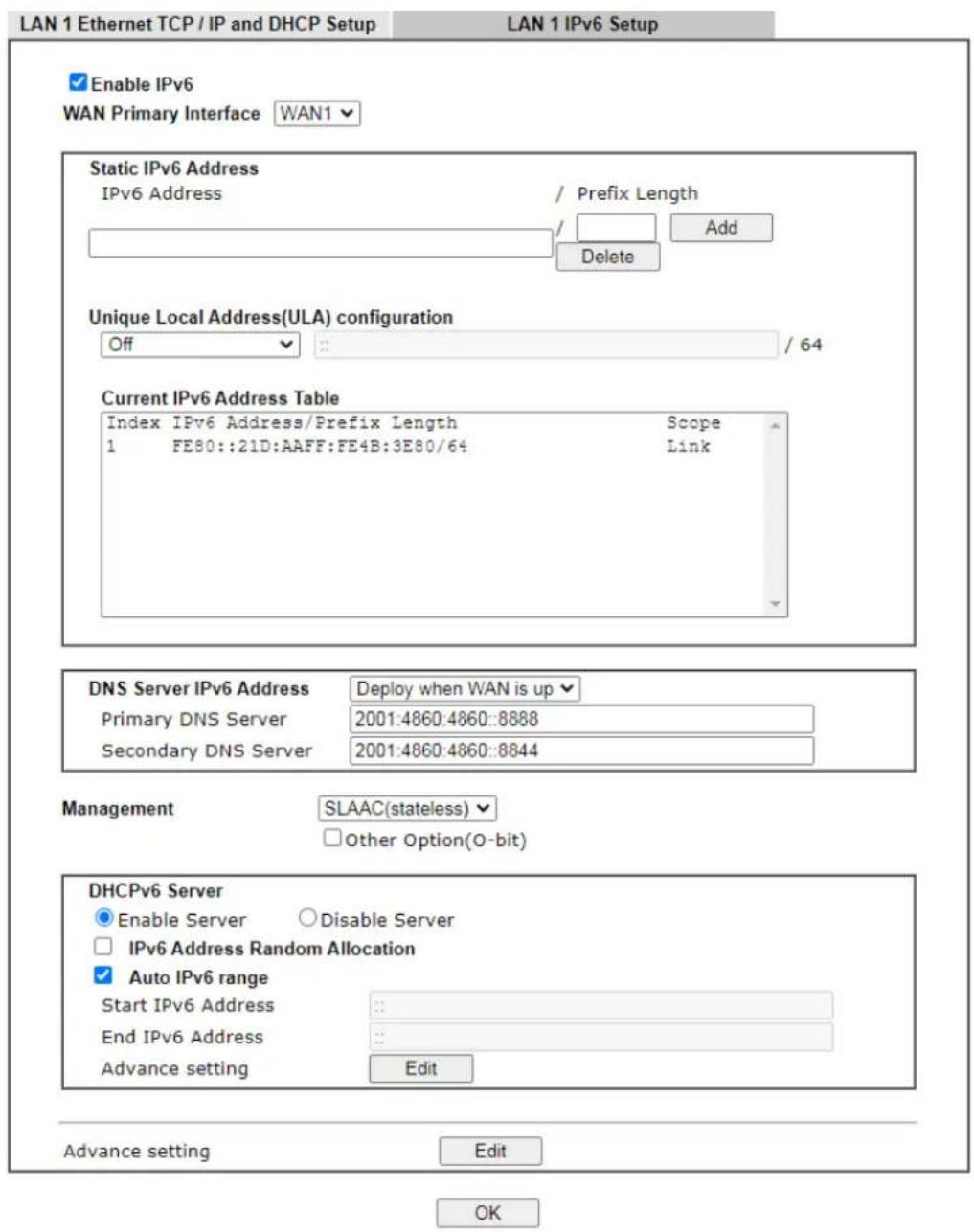
It provides 2 daemons for LAN side IPv6 address configuration. One is SLAAC(stateless) and the other is DHCPv6 Server (Stateful).
Available settings are explained as follows:
| Item | Description |
| Enable IPv6 Enables or disables IPv6 on the LAN. | |
| WAN Primary Interface Select the WAN to be used for IPv6 traffic. | |
| Static IPv6 Address Enter | Pv6 Address and Prefix length to be added, or click an existing IPv6 address to be deleted in the Current IPv6 Address Table below and the values will be automatically copied over.IPv6 Address-Type static IPv6 address for LANPrefix Length - Enter the fixed value for prefix length.Add - Click it to add a new entry.Delete - Click it to remove an existed entry. |
| Unique Local Address (ULA) configuration | Unique Local Addresses (ULAs) are private IPv6 addresses assigned to LAN clients.Off - ULA is disabled.Manually ULA Prefix - LAN clients will be assigned ULAs generated based on the prefix manually entered.Auto ULA Prefix - LAN clients will be assigned ULAs using an automatically-determined prefix. |
| Current IPv6 Address Table | Display current used IPv6 addresses. |
| DNS Server IPv6 Address Deploy when WAN is up - The RA (router advertisement) packets will be sent to LAN PC with DNS server information only when network connection by any one of WAN interfaces is up.Enable - The RA (router advertisement) packets will be sent to LAN PC with DNS server information no matter WAN connection is up or not.Primary DNS Sever - Enter the IPv6 address for Primary DNS server.Secondary DNS Server -Type another IPv6 address for DNS server if required.Disable - DNS server will not be used. | |
| Management | Configures the Managed Address Configuration flag (M-bit) in Route Advertisements.Off - No configuration information is sent using Route Advertisements.SLAAC(stateless) - M-bit is unset.DHCPv6(stateful) - M-bit is set, which indicates to LAN clients that they should acquire all IPv6 configuration information from a DHCPv6 server. The DHCPv6 server can either be the one built into the Vigor2860, or a separate DHCPv6 server.Other Option (O-bit) - When selected, the OtherConfiguration flag is set, which indicates to LAN clients that IPv6 configuration information besides LAN IPv6 addresses is available from a DHCPv6 server.Setting the M-bit (see Management above) has the same effect as implicitly setting the O-bit, as DHCPv6 supplies all IPv6 configuration information, including what is indicated as available when the O-bit is set. |
| Other Option(O-bit) | When selected, theOther Configurationflag is set, which indicates to LAN clients that IPv6 configuration information besides LAN IPv6 addresses is available from a DHCPv6 server.Setting the M-bit (seeManagementabove) has the same effect as implicitly setting the O-bit, as DHCPv6 supplies all IPv6 configuration information, including what is indicated as available when the O-bit is set. |
| DHCPv6 Server Enable Server | -Click it to enable DHCPv6 server. DHCPv6Server could assign IPv6 address to PC according to the Start/ End IPv6 address configuration.Disable Server -Click it to disable DHCPv6 server.IPv6 Address Random Allocation - Check it to assign the DHCPv6 IP address randomly to prevent the attacks from the IPv6 reconnaissance techniques.Auto IPv6 range - When selected, the router’s built-in DHCPv6 server decides the LAN IPv6 address range to be used. When deselected, LAN IPv6 addresses given out will be within the range as specified in theStart IPv6 AddressandEnd IPv6 Address.Start IPv6 Address / End IPv6 Address -Enter the start and end address for IPv6 server.Advance setting - Click theEditbutton to bring up the IPv6 Advanced Settings page.LAN >> General Setup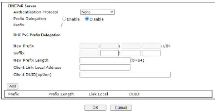 |
| Advance setting The Advanced Settings page has additional settings for Router Advertisement and enabling multiple WANs for IPv6 traffic. | |
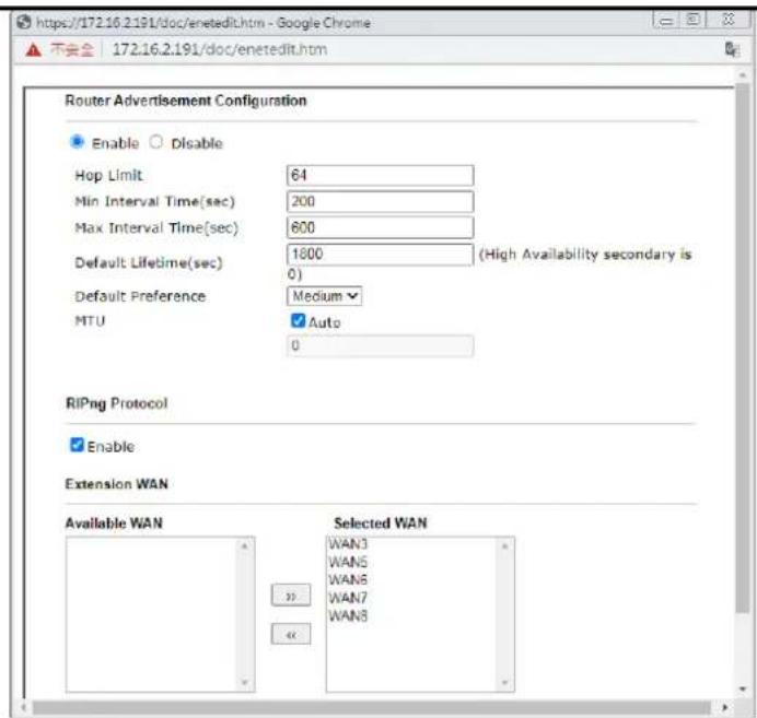
Router Advertisement Configuration - Click Enable to enable router advertisement server. The router advertisement daemon sends Router Advertisement messages, specified by RFC 2461, to a local Ethernet LAN periodically and when requested by a node sending a Router Solicitation message. These messages are required for IPv6 stateless auto-configuration.
Disable - Click it to disable router advertisement server.
Hop Limit - The value is required for the device behind the router when IPv6 is in use. Default value of hop limit field in Route Advertisement messages.
Min/Max Interval Time (sec) - Minimum/ Maximum time, in seconds, between unsolicited multicast route advertisement messages sent by the RA server.
Default Lifetime (sec) - Time, in seconds, that the router is to be used as the default router.
Default Preference - Default preference value (Low, Medium, High) of the router sent in route advertisement messages.
MTU - It means Max Transmit Unit for packet. If Auto is selected, the router determines the MTU value to send in route advertisement messages.
RIPng Protocol - RIPng (RIP next generation) offers the same functions and benefits as IPv4 RIP v2.
Extension WAN - In addition to the default WAN used for IPv6 traffic specified in the WAN Primary Interface in the LAN IPv6 Setup page, additional WANs can be selected to carry IPv6 traffic by enabling them in the Extension WAN section.
Available WAN - Additional WANs available but not currently selected to carry IPv6 traffic.
Selected WAN - Additional WANs selected to carry IPv6 traffic.
After making changes on the Advance setting page, click the OK button to retain the changes and return to the LAN IPv6 Setup page. Be sure to click OK on the LAN IPv6 Setup page or else changes made on the Advance setting page will not be saved.
II-3-1-4 DHCP Server Option
DHCP Options can be configured by clicking the Advanced button on the LAN General Setup screen.
LAN >> General Setup
DHCP Server Customized Status
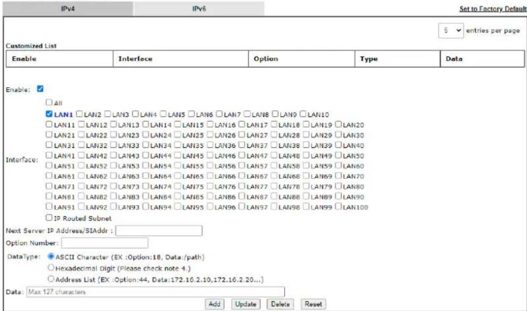
Available settings are explained as follows:
| Item | Description |
| Customized List Shows all the DHCP options that have been configured in the system. | |
| Enable If selected, DHCP option entry is enabled.If unselected, DHCP option entry is disabled. | |
| Interface LAN interface(s) to which this entry is applicable. | |
| Next Server IPAddress/SIAddr | Overrides the DHCP Next Server IP address (DHCP Option 66) supplied by the DHCP server. |
| Option Number DHCP option number (e.g., 100). | |
| DataType Type of data in the Data field:ASCII Character - A text string. Example: / path.Hexadecimal Digit - A hexadecimal string. Valid characters are from 0 to 9 and from a to f. Example: 2f70617468.Address List - One or more IPv4 addresses, delimited by commas. | |
| Data Data of this DHCP option. | |
| Add To add a DHCP option entry modeled after an existing entry,click the model entry in Customized List. The data entry fields will be populated with values from the model entry.After making all necessary changes for the new entry, click Add to create it. | |
| Update To modify an existing DHCP option entry, click on it inCustomized List. The data entry fields will be populated with the current values from the entry. After making all | |
| necessary changes, clickUpdateto save the changes. | |
| Delete | To delete a DHCP option entry, click on it inCustomized List, and then clickDelete. |
| Reset Clear the current settings. | |
II-3-2 VLAN
Virtual Local Area Networks (VLANs) allow you to subdivide your LAN to facilitate management or to improve network security.
Select LAN>>VLAN from the menu bar of the Web UI to bring up the VLAN Configuration page.
Tagged VLAN
The tagged VLANs (802.1q) can mark data with a VLAN identifier. This identifier can be carried through an onward Ethernet switch to specific ports. The specific VLAN clients can also pick up this identifier as it is just passed to the LAN. You can set the priorities for LAN-side QoS. You can assign each of VLANs to each of the different IP subnets that the router may also be operating, to provide even more isolation. The said functionality is tag-based multi-subnet.
LAN >> VLAN Configuration
VLAN Configuration
Settings in this page only applied to LAN port but not WAN port.
Available settings are explained as follows:
| Item | Description |
| Enable Enables or disables VLAN functionality. | |
| VLAN# Virtual LANs. | |
| LAN Port P2 - P12 - Physical | Ethernet ports on the router. Select the LAN port(s) to group them under the selected VLAN. |
| Subnet Select a LAN subnet | from LAN 1 to LAN 100 to make the selected VLAN mapping to the specified subnet only. |
| VLAN Tag | Enable - Select to enable 802.1Q tagging on this VLAN.The router will add specific VLAN number to all packets on the LAN while sending them out.Please enter the tag value and specify the priority for the packets sending by LAN.VID - VLAN Identifier. Valid values are form 0 to 4095. VIDs must be unique.Priority - Valid values are from 0 to 7, where 1 has the lowest priority, followed by 0, and finally from 2 to 7 in increasing order of priority. |
| Permit untagged device in P12 to access router | Select to allow untagged hosts connected to LAN port P12 to access the router. In case you have incorrectly configured VLAN functionality, you will still be able to access the router via the Web UI, and telnet and SSH shells to adjust the configuration. |
Inter-LAN Routing
The Vigor router supports up to 99 VLANs. Each VLAN can be set up to use one or more of the Ethernet ports and wireless LAN Service Set Identifiers (SSIDs). Within the grid of VLANs (horizontal rows) and LAN interfaces (vertical columns),
● all hosts within the same VLAN (horizontal row) are visible to one another
● all hosts connected to the same LAN or WLAN interface (vertical column) are visible to one another if
- they belong to the same VLAN, or
- they belong to different VLANs, and inter-LAN routing (LAN>>General Setup) between them is enabled (see below).
LAN >> General Setup
General Setup
| Index | Description | Enable | DHCP | IP Address | ||
| LAN 1 | V | V | 192.168.100.1 | Details Page | IPv6 | |
| IP Routed Subnet | ☐ | ☐ | 192.168.0.1 | Details Page |
DHCP Server Option
Note:
Please enable LAN 2 - 100 on LAN >> VLAN page before configure them.
☐ Force router to use "DNS server IP address" settings specified in LAN1
Inter-LAN Routing
| Subnet | LAN 1 | LAN 2 | LAN 3 | LAN 4 | LAN 5 | LAN 6 | LAN 7 | LAN 8 | LAN 9 | LAN 10 | LAN 11 | LAN 12 | LAN 13 | LAN 14 | LAN 15 | LAN 16 | LAN 17 | LAN 18 |
| LAN 1 | ||||||||||||||||||
| LAN 2 | ||||||||||||||||||
| LAN 3 | ||||||||||||||||||
| LAN 4 | ||||||||||||||||||
| LAN 5 | ||||||||||||||||||
| LAN 6 |
OK
Inter-LAN Routing allows different LAN subnets to be interconnected or isolated. It is only available when the VLAN functionality is enabled. In the Inter-LAN Routing matrix, a selected checkbox means that the 2 intersecting LANs can communicate with each other.
Vigor router features a hugely flexible VLAN system. In its simplest form, each of the Gigabit LAN ports can be isolated from each other, for example to feed different companies or departments but keeping their local traffic completely separated.
II-3-3 Bind IP to MAC
This function is used to bind the IP and MAC address in LAN to have a strengthening control in network. With the Bind IP to MAC feature you can reserve LAN IP addresses for LAN clients. Each reserved IP address is associated with a Media Access Control (MAC) address.
Click LAN and click Bind IP to MAC to open the setup page.
LAN >> Bind IP to MAC
Bind IP to MAC
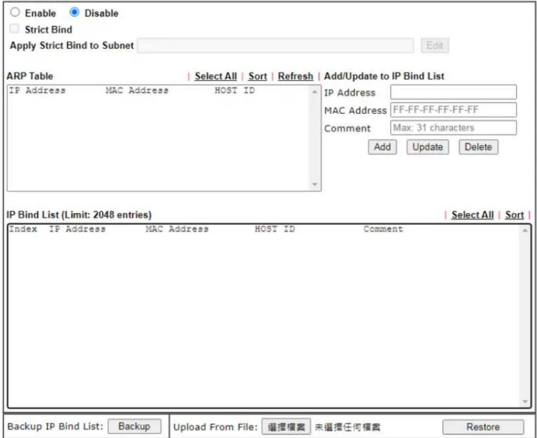
Available settings are explained as follows:
| Item | Description |
| Enable MAC addresses that have an IP address assigned on this page will receive that IP address through DHCP. | |
| Disable | MAC address-to-IP address bindings configured on this page are ignored by the DHCP server when assigning IP addresses through DHCP. |
| Strict Bind Check the box to block the connection of the IP/ MAC which is not listed in IP Bind List.LAN clients will be assigned IP addresses according to the MAC-to-IP address associations on this page. LAN client whose MAC address has not been bound to an IP address will be denied network access. | |
Note: Before selecting Strict Bind, make sure at least one valid MAC address has been bound to an IP address. Otherwise no LAN clients will have network access, and it will not be possible to connect to the router to make changes to its configuration.Apply Strict Bind to Subnet - Choose the subnet(s) for applying the rules of Bind IP to MAC.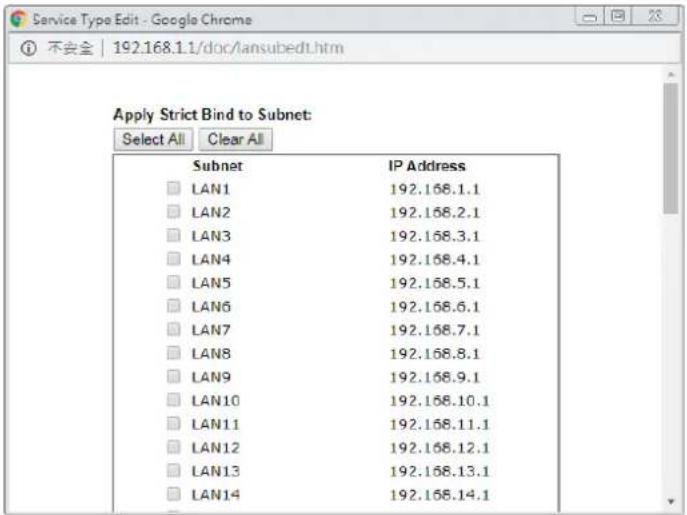 | |
| ARP Table This table is the | LAN ARP table of this router. The information for IP and MAC will be displayed in this field. Each pair of IP and MAC address listed in ARP table can be selected and added to IP Bind List by clicking Add below. |
| Select All Select all entries | in the ARP Table for manipulation. |
| Sort Sort the entries in the | ARP Table by IP address. |
| Refresh Refresh the screen | to reflect the current state of the ARP table. |
| Add / Update to IP Bind List | IP Address - Enter the IP address to be associated with a MAC address.Mac Address - Enter the MAC address of the LAN client's network interface.Comment - Optional comment field to identify this IP Address - MAC Address pair. |
| Add | It allows you to add the one you choose from the ARP table or the IP/ MAC address typed in Add and Edit to the table of IP Bind List. |
| Update It allows you to edit | and modify the selected IP address and MAC address that you create before. |
| Delete | You can remove any item listed in IP Bind List. Simply click and select the one, and click Delete. The selected item will be removed from the IP Bind List. |
| IP Bind List | It displays a list for the IP bind to MAC information. |
| Backup IP Bind List | Click Backup and enter a filename to back up IP Bind List to a file. |
| Upload From File | Click Browse... to select an IP Bind List backup file. Click Restore to restore the backup and overwrite the existing list. |

Info
Before you select Strict Bind, you have to bind one set of IP/MAC address for one PC. If not, no one of the PCs can access into Internet. And the web user interface of the router might not be accessed.
When you finish the configuration, click OK to save the settings.
II-3-4 Port Mirror/Packet Capture
The LAN Port Mirror function allows network traffic of select LAN ports to be forwarded to another LAN port for analysis. This is useful for enforcing policies, detecting unauthorized access, monitoring network performance, etc.
Select LAN>>LAN Port Mirror from the menu bar of the Web UI to bring up the LAN Port Mirror configuration page.
If selecing "Continuously Send All Packets to Mirror Port", the setting page will be shown as follows:
LAN >> Port Mirror/Packet Capture
Continuously Send All Packets to Mirror Port
○ Download .pcap
Available settings are explained as follows:
| Item | Description |
| Continuously Send All Packets to Mirror Port | Select to send all packets to mirror port. |
| Enable/Disable Select Enable | to activate the function.Select Disable to cancel the function. |
| Mirror Port One and only one | port is selected as the mirror port, to which traffic is to be forwarded. |
| Mirrored Tx Port Port(s) whose outbound traffic will be forwarded to the mirror port. | |
| Mirrored Rx Port | Port(s) whose inbound traffic will be forwarded to the mirror port. |
| OK Save the settings. | |
If selecing "Download .pcap", the setting page will be shown as follows:
LAN >> Port Mirror/Packet Capture
○ Continuously Send All Packets to Mirror Port Download .pcap
| P1 WAN1 | P2 LAN | P3 WAN3 | P4 LAN | P5 WAN5 | P6 WAN6 | P7 WAN7 | P8 WAN8 | P9 LAN | P10 LAN | P11 LAN | P12 LAN | |
| Mirror Port | ||||||||||||
| Mirrored Tx Port | ||||||||||||
| Mirrored Rx Port |
Status: Idle
Setting ○ Capture All Packets
Capture with Filter
Duration 60 (seconds)
Filter Settings

Available settings are explained as follows:
| Item | Description |
| Download .pcap If it is selected, the packets from the specified mirror port can be downloaded for analysis. | |
| Mirror Port One and only one port is selected as the mirror port, to which traffic is to be forwarded. | |
| Mirrored Tx Port Port(s) whose outbound traffic will be forwarded to the mirror port. | |
| Mirrored Rx Port | Port(s) whose inbound traffic will be forwarded to the mirror port. |
| Setting Capture All Packets - All packets will be captured for analysisCapture with Filter - Only the packets filtered by ICMP, TCP, UDP, or TCP/ UDP will be captured for analysis. | |
| Duration Set a period of time for Vigor router to capture the packets. | |
| Filter Settings | It is available only when Capture with Filter is selected.Protocol - Filter the packet by using Any, ICMP, TCP, UDP, and TCP/ UDP.IP Address - Filter the packet by IP address. If Customized IP is selected, please enter an IP address in the entry box.Port - It is available when TCP, UDP, or TCP/ UDP is selected as the Protocol. Select Any or Customize Port. If Customize Port is selected, please enter a port number in the entry box. |
| Start Click to begin the packet capturing. | |
| Diagnostics >> Port Mirror/Packet Capture | |||
| Continuously Send All Packets to Mirror PortDownload .pcap | |||
| P1WAN1 | P2WAN2 | ||
| Mirror Port | |||
| Mirrored Tx Port | ✓ | ✓ | |
| Mirrored Rx Port | ✓ | ✓ | |
| Status: CapturingSetting Capture All Packets Capture with FilterDuration 60 (seconds)Start Stop Down! | |||
| Stop Click to terminate the scanning job. | |||
| Download | Click to download the packet capture result as a file with the file format,.pcap. | ||
After finishing all the settings here, please click OK to save the configuration.
II-3-5 Wired 802.1x
Wired 802.1X provides authentication for clients wishing to connect to the LAN by Ethernet. Only one client can be authenticated on each LAN port.
Select LAN>>Wired 802.1X from the menu bar of the Web UI to bring up the Wired 802.1X configuration page.
LAN >> Wired 802.1X
Wired 802.1X
LAN 802.1X:
Enable
Authentication Type: External RADIUS
802.1X ports:
□ p9
□P10
□P11
□P12
Note:
- 802.1X enabled LAN ports only support a single attached device using EAPOL authentication. To authenticate multiple devices through a LAN port you need an 802.1X-capable switch. Then configure 802.1X on the attached switch instead.
- Please configure External RADIUS or Local 802.1X for authentication.
- Authentication by External RADIUS supports PEAP, EAP-TLS and EAP-TTLS.
OK
Available settings are explained as follows:
| Item | Description |
| Enable Check the box to enable LAN 802.1x function. | |
| Authentication Type | External RADIUS - An external RADIUS server is to be used for 802.1X authentication. Go to Applications >> RADIUS / TACACS+>>External RADIUS to specify the RADIUS server.Local 802.1X - Use the user database on the router toauthenticate clients. Go toUser Management >> User Profileto set up users by entering user names, passwords and ensure that Local 802.1X service is enabled for the profiles. |
| 802.1X ports 802.1X authentication will be available for the selected LAN ports. | |
After finishing all the settings here, please click OK to save the configuration.
II-3-6 PPPoE Server
LAN users can access into Internet through built-in PPPoE server on Vigor router. PPPoE server is a mechanism which can authenticate LAN users (configured in User Management>>User Profile) and prevent ARP attack completely.
LAN >> PPPoE Server
PPPoE Server

OK
Available settings are explained as follows:
| Item | Description |
| PPPoE Server Enable - Activate the built-in PPPoE Server. | ate the built-in PPPoE Server. |
| Disable - Disable the built-in PPPoE Server. | |
| Primary DNS / Secondary DNS | Type the IP address(es) of Primary / Secondary DNS server for PPPoE Client(s) in LAN. |
II-4 NAT
Most ISPs allocate one WAN IP address to each subscriber. In order to simultaneously connect multiple devices to the Internet, a technique called Network Address Translation is employed.
Usually, the router serves as an NAT (Network Address Translation) router. NAT is a mechanism that one or more private IP addresses can be mapped into a single public one. Public IP address is usually assigned by your ISP, for which you may get charged. Private IP addresses are recognized only among internal hosts.
When the outgoing packets destined to some public server on the Internet reach the NAT router, the router will change its source address into the public IP address of the router, select the available public port, and then forward it. At the same time, the router shall list an entry in a table to memorize this address/ port-mapping relationship. When the public server response, the incoming traffic, of course, is destined to the router's public IP address and the router will do the inversion based on its table. Therefore, the internal host can communicate with external host smoothly.
The benefit of the NAT includes:
- Save cost on applying public IP address and apply efficient usage of IP address. NAT allows the internal IP addresses of local hosts to be translated into one public IP address, thus you can have only one IP address on behalf of the entire internal hosts.
● Enhance security of the internal network by obscuring the IP address. There are many attacks aiming victims based on the IP address. Since the attacker cannot be aware of any private IP addresses, the NAT function can protect the internal network.

Info
On NAT page, you will see the private IP address defined in RFC-1918. Usually we use the 192.168.1.0/24 subnet for the router. As stated before, the NAT facility can map one or more IP addresses and/or service ports into different specified services. In other words, the NAT function can be achieved by using port mapping methods.
Web User Interface
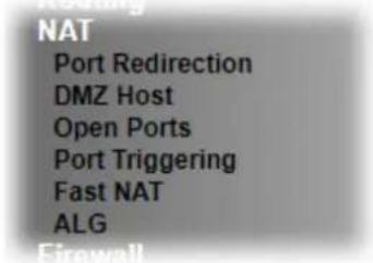
II-4-1 Port Redirection
Port Redirection is usually set up for server related service inside the local network (LAN), such as web servers, FTP servers, E-mail servers etc. Most of the case, you need a public IP address for each server and this public IP address/ domain name are recognized by all users. Since the server is actually located inside the LAN, the network well protected by NAT of the router, and identified by its private IP address/ port, the goal of Port Redirection function is to forward all access request with public IP address from external users to the mapping private IP address/ port of the server.
Most ISPs allocate one WAN IP address to each subscriber. In order to simultaneously connect multiple devices to the Internet, a technique called Network Address Translation is employed.
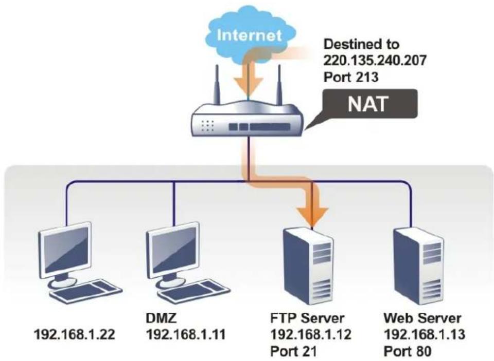
flowchart
graph TD
    A["Internet"] --> B["NAT"]
    B --> C["DMZ 192.168.1.22"]
    B --> D["DMZ 192.168.1.11"]
    B --> E["FTP Server 192.168.1.12 Port 21"]
    B --> F["Web Server 192.168.1.13 Port 80"]
    G["Destined to 220.135.240.207 Port 213"] --> B
The port redirection can only apply to incoming traffic.
To use this function, please go to NAT page and choose Port Redirection web page. The Port Redirection Table provides 520 port-mapping entries for the internal hosts.
| Port Redirection | 50 rules per page | Set to Factory DefaultClear selected | ||||||
| Index | Enable | Service Name | WAN Interface | Protocol | Public Port | Source IP | Private IP | Select |
| 1. | √ | test636 | ALL | TCP | 2780 | Any | 192.168.13.10 | □ |
| 2. | □ | ALL | Any | □ | ||||
| 3. | □ | ALL | Any | □ | ||||
| 4. | □ | ALL | Any | □ | ||||
| 5. | □ | ALL | Any | □ | ||||
| 6. | □ | ALL | Any | □ | ||||
| 7. | □ | ALL | Any | □ | ||||
| 8. | □ | ALL | Any | □ | ||||
| 9. | □ | ALL | Any | □ | ||||
| 10. | □ | ALL | Any | □ | ||||
| 11. | □ | ALL | Any | □ | ||||
| 12. | □ | ALL | Any | □ | ||||
Each item is explained as follows:
| Item | Description |
| Index Click to view and edit details of the rule. | |
| Enable Select to enable the port redirection rule. | |
| Service Name User-entered name that identifies the rule. | |
| WAN Interface WAN interface(s) to which this rule applies. A particular WAN interface or ALL interfaces. | |
| Protocol The protocol to which this rule applies, TCP or UDP. | |
| Public Port The port or range of WAN ports that is redirected by this rule. | |
| Source IP The IP object of the source IP. | |
| Private IP | The LAN IP address(es) to which the traffic is redirected. |
| Backup Click it to backup the configuration of port redirection settings. | |
| Restore Click it to restore the configuration of port redirection settings. Before clicking, make sure upload the configuration file onto Vigor router. | |
Press any number under Index to access into next page for configuring port redirection.
Index No. 1
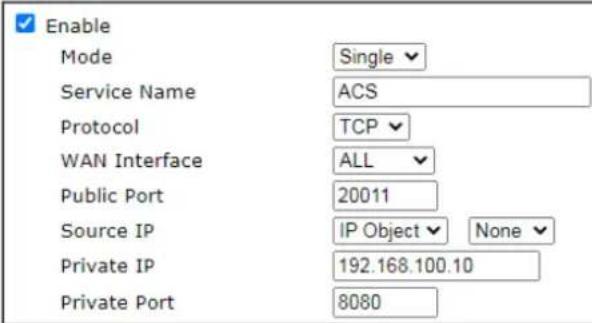
Note:
In "Range" Mode the End IP will be calculated automatically once the Public Port and Start IP have been entered.

Available settings are explained as follows:
| Item | Description |
| Enable | Select to enable the port redirection setting. |
| Mode Allows a single port or | a range of ports to be redirected.Single - redirects one single port.Range - redirects a contiguous range of ports. |
| Service Name Enter the description of the specific network service. | |
| Protocol The protocol to which this rule applies, TCP or UDP. | |
| WAN Interface WAN interface(s) to which this rule applies.WAN # - Traffic from the selected WAN interface will be redirected.ALL - Traffic from all WAN interfaces will be redirected. | |
| Public Port | Specify which port can be redirected to the specified Private IP and Port of the internal host. If you choose Range as the port redirection mode, you will see two boxes on this field.Enter the required number on the first box (as the starting port) and the second box (as the ending port). |
| Source IP IP Object - Use the drop down list to specify an IP object profile.IP Group - Use the drop down list to specify an IP group profile. | |
| Private IP | The LAN IP address or range of IP addresses to which the traffic is redirected. In the case of a range, only the beginning IP address needs to be entered. The ending IP address will automatically be derived from the number of public ports. |
| Private Port The port on each LAN client to which the traffic will be directed to. | |
After finishing all the settings here, please click OK to save the configuration.
Note that the router has its own built-in services (servers) such as Telnet, HTTP and FTP etc. Since the common port numbers of these services (servers) are all the same, you may need to reset the router in order to avoid confliction.
For example, the built-in web user interface in the router is with default port 80, which may conflict with the web server in the local network, http://192.168.1.13:80. Therefore, you need to change the router's http port to any one other than the default port 80 to avoid conflict, such as 8080. This can be set in the System Maintenance >>Management Setup. You then will access the admin screen of by suffixing the IP address with 8080, e.g., http://192.168.1.1:8080 instead of port 80.
System Maintenance >> Management


II-4-2 DMZ Host
As mentioned above, Port Redirection can redirect incoming TCP/UDP or other traffic on particular ports to the specific private IP address/port of host in the LAN. However, other IP protocols, for example Protocols 50 (ESP) and 51 (AH), do not travel on a fixed port. Vigor router provides a facility DMZ Host that maps ALL unsolicited data on any protocol to a single host in the LAN. Regular web surfing and other such Internet activities from other clients will continue to work without inappropriate interruption. DMZ Host allows a defined internal user to be totally exposed to the Internet, which usually helps some special applications such as Netmeeting or Internet Games etc.

flowchart
graph TD
    A["Internet"] --> B["NAT"]
    B --> C["DMZ 192.168.1.22"]
    B --> D["FTP Server 192.168.1.12 Port 21"]
    B --> E["Web Server 192.168.1.13 Port 80"]
    A --> F["Destination: 220.135.240.207\nProtocol: Any\nPort: Any"]
The security properties of NAT are somewhat bypassed if you set up DMZ host. We suggest you to add additional filter rules or a secondary firewall.
Click DMZ Host to open the following page. You can set different DMZ host for each WAN interface. Click the WAN tab to switch into the configuration page for that WAN.
NAT >> DMZ Host Setup
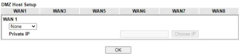
Available settings are explained as follows:
| Item | Description |
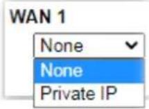 | Enables or disables DMZ host.None - Disables DMZ host function.Private IP - Allows WAN traffic to be sent to a specific LAN IP address. |
| Private IP | If Private IP mode has been selected, click the Choose IP button to select a LAN IP address. |
| Choose IP | Click this button and then a window will automatically pop up, as depicted below. The window consists of a list of private IP addresses of all hosts in your LAN network. Select one private IP address in the list to be the DMZ host.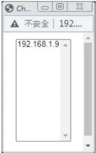 When you have selected one private IP from the above dialog, the IP address will be shown on the screen. Click OK to save the setting. When you have selected one private IP from the above dialog, the IP address will be shown on the screen. Click OK to save the setting. |
DMZ Host for other WAN interface is slightly different with WAN1. Active True IP selection is available for WAN1 only.
See the following figure.
NAT >> DMZ Host Setup

If you previously have set up WAN Alias for PPPoE or Static or Dynamic IP mode in WAN2 interface, you will find them in Aux. WAN IP for your selection.
NAT >> DMZ Host Setup
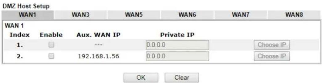
Available settings are explained as follows:
| Item | Description |
| Enable Check to enable the | DMZ Host function. |
| Private IP Enter the private | IP address of the DMZ host, or click Choose PC to select one. |
| Choose IP | Click this button and then a window will automatically pop up, as depicted below. The window consists of a list of private IP addresses of all hosts in your LAN network. Select one private IP address in the list to be the DMZ host.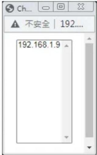 When you have selected one private IP from the above dialog, the IP address will be shown on the screen. Click OK to save the setting. When you have selected one private IP from the above dialog, the IP address will be shown on the screen. Click OK to save the setting. |
After finishing all the settings here, please click OK to save the configuration.
II-4-3 Open Ports
The Open Ports function allows inbound traffic from specific ports on WAN interfaces to be forwarded to LAN clients. Unlike Port Redirection, LAN client ports cannot be remapped and must remain identical to the opened ports on the WAN interface.
It allows you to open a range of ports for the traffic of special applications.
The common application of Open Ports includes P2P application (e.g., BT, KaZaA, Gnutella, WinMX, eMule, and others), Internet Camera, etc. Ensure that you keep the application involved up-to-date to avoid falling victim to any security exploits.
NAT >> Open Ports
| Open Ports Setup50 rules per page Set to Factory Default Clear selected | ||||||
| Index | Enable | Comment | WAN Interface | Source IP | Local IP Address | select |
| 1. | □ | Any | □ | |||
| 2. | □ | Any | □ | |||
| 3. | □ | Any | □ | |||
| 4. | □ | Any | □ | |||
| 5. | □ | Any | □ | |||
| 6. | □ | Any | □ | |||
| 7. | □ | Any | □ | |||
| 8. | □ | Any | □ | |||
| 9. | □ | Any | □ | |||
| 10. | □ | Any | □ | |||
| 11. | □ | Any | □ | |||
| 12. | □ | Any | □ | |||
| 13. | □ | Any | □ | |||
| 14. | □ | Any | □ | |||
Available settings are explained as follows:
| Item | Description |
| Index | Indicate the relative number for the particular entry (1 to 260) that you want to offer service in a local host. Click to view and edit the rule. |
| Enable Select the box to enable the open port rule. | |
| Comment User-entered label that identifies the rule. | |
| WAN Interface The WAN port(s) whose incoming traffic will be forwarded to a LAN client. | |
| Aux. WAN IP Display the IP alias setting used by such index.If no IP alias setting exists, this field will not appear. | |
| Source IP The IP object of the source IP. | |
| Local IP Address | LAN client to receive the forwarded WAN traffic. |
To add or edit port settings, click one index number on the page. The index entry setup page will pop up. In each index entry, you can specify 10 port ranges for diverse services.
Index No. 1
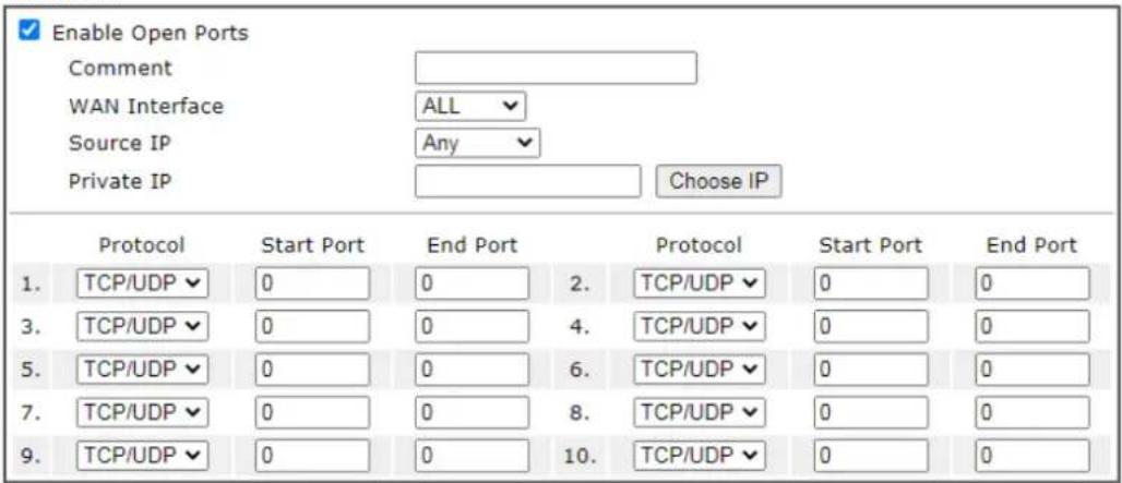

Available settings are explained as follows:
| Item | Description |
| Enable Open Ports Select to enable this rule. | |
| Comment User-entered label that identifies the rule. | |
| WAN Interface The WAN port(s) whose incoming traffic will be forwarded to a LAN client. Select from a specific WAN interface WAN1 to WAN6, or choose ALL to apply the rule to all WAN interfaces. | |
| WAN IP Specify the WAN IP address that will be used for this entry.This setting is available when WAN IP Alias is configured. | |
| Source IP Any - Any IP can be used as the source IP.IP Object - Use the drop down list to specify an IP object profile.IP Group - Use the drop down list to specify an IP group profile. | |
| Private IP IP address of LAN client to receive the forwarded WANtraffic. Click Choose IP to select.Choose IP - Click this button and, subsequently, a window having a list of private IP addresses of local hosts will automatically pop up. Select the appropriate IP address of the local host in the list. | |
| Protocol The protocol(s) to which this rule applies.TCP - forward only TCP traffic.UDP - forward only UDP traffic.TCP/UDP - forward both TCP and UDP traffic. | |
| Start Port The port number of the starting port to be forwarded. | |
| End Port The port number of the ending port to be forwarded. If only one port is to be forwarded, enter the same port number as the Start Port. | |
After finishing all the settings here, please click OK to save the configuration.
NAT >> Open Ports
| Open Ports Setup50 rules per page | Set to Factory Default | |||||
| Index | Enable | Comment | WAN Interface | Source IP | Local IP Address |
| 1. | √ | CARR_1 | ALL | Any | 192.168.1.9 |
| 2. | □ | Any | |||
| 3. | □ | Any | |||
| 4. | □ | Any | |||
| 5. | □ | Any | |||
| 6. | □ | Any | |||
| 7. | □ | Any | |||
II-4-4 Port Triggering
If you run programs that function as server applications where they expect to receive unsolicited traffic from the WAN, you can set up rules in Port Triggering to detect LAN-to-WAN traffic initiated by those programs, and automatically open up WAN ports to accept incoming traffic and forward it to the LAN client running the server applications.
Port Triggering is a variation of open ports function.
The key difference between "open port" and "port triggering" is:
- Once the OK button is clicked and the configuration has taken effect, "open port" keeps the ports opened forever.
- Once the OK button is clicked and the configuration has taken effect, "port triggering" will only attempt to open the ports once the triggering conditions are met.
- The duration that these ports are opened depends on the type of protocol used. The "default" durations are shown below and these duration values can be modified via telnet commands.
TCP: 86400 sec.
UDP: 180 sec.
IGMP: 10 sec.
TCP WWW: 60 sec.
TCP SYN: 60 sec.
Port Triggering
Set to Factory Default
| Index | Enable | Comment | Triggering Protocol | Source IP | Triggering Port | Incoming Protocol | Incoming Port |
| 1. | Any | ||||||
| 2. | Any | ||||||
| 3. | Any | ||||||
| 4. | Any | ||||||
| 5. | Any | ||||||
| 6. | Any | ||||||
| 7. | Any | ||||||
| 8. | Any | ||||||
| 9. | Any | ||||||
| 10. | Any | ||||||
| 11. | Any | ||||||
| 12. | Any | ||||||
| 13. | Any | ||||||
| 14. | Any | ||||||
| 15. | Any | ||||||
| 16. | Any | ||||||
| 17. | Any | ||||||
| 18. | Any | ||||||
| 19. | Any | ||||||
| 20. | Any |


OK
Cancel
Available settings are explained as follows:
| Item | Description |
| Index Rule number. Click to | view or modify rule settings. |
| Enable Select to enable the | Port Triggering rule. |
| Comment User-entered label that identifies the rule. | |
| Triggering Protocol The protocol(s) of the outgoing traffic that this rule monitors.TCP- monitor only TCP traffic.UDP- monitor only UDP traffic.TCP/UDP- monitor both TCP and UDP traffic. | |
| Source IP The IP object of the source IP. | |
| Triggering Port Display the port of the triggering packets. | |
| Incoming Protocol Display the protocol for the incoming data of such triggering profile.The protocol(s) of the incoming traffic.TCP-open port(s) to TCP traffic.UDP- open port(s) to UDP traffic.TCP/UDP- open port(s) to both TCP and UDP traffic. | |
| Incoming Port Display the port for the incoming data. | |
| Incoming traffic from the WAN destined for these port numbers be forwarded to the LAN client that triggered the rule. | |
Click the index number link to open the configuration page.
NAT >> Port Triggering
No. 1
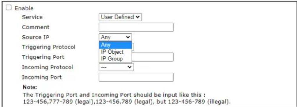

Available settings are explained as follows:
| Item | Description |
| Enable Select to enable rule. | |
| Service | Select from list of predefined service, or User Defined to manually configure triggering and incoming protocols and ports. |
| Comment Enter the text to memorize the application of this rule. | |
| Source IP Any - Any IP can be used as the source IP.IP Object - Use the drop down list to specify an IP object profile.IP Group - Use the drop down list to specify an IP group profile. | |
| Triggering Protocol The protocol(s) of the outgoing traffic that this rule monitors.TCP - monitor only TCP traffic.UDP - monitor only UDP traffic.TCP/UDP - monitor both TCP and UDP traffic. | |
| Triggering Port Outgoing traffic destined for these port numbers will trigger the opening WAN ports to incoming traffic.Enter the port or port range for such triggering profile. | |
| Incoming Protocol The protocol(s) of the incoming traffic.TCP-open port(s) to TCP traffic.UDP- open port(s) to UDP traffic.TCP/UDP- open port(s) to both TCP and UDP traffic.Select the protocol (TCP, UDP or TCP/UDP) for the incoming data of such triggering profile. | |
| Incoming Port | Incoming traffic from the WAN destined for these port numbers be forwarded to the LAN client that triggered therule.Enter the port or port range for the incoming packets. |
After finishing all the settings here, please click OK to save the configuration.
Open Port and Port Triggering Compared
| Port Triggering Open Port | |
| Ports are opened when the triggering condition is met. | Ports are always open on the WAN interface. |
| Opened ports will be closed after predefined durations have elapsed.Default duration values vary depending on the protocol and traffic content:TCP (all TCP ports, except those that pass HTTP and HTTPS traffic): 86400 secondsUDP: 180 secondsTCP WWW (TCP ports that engage in HTTP and HTTPS communication): 60 secondsTCP SYN: 60 seconds (SYN packets expire after 60 seconds)These values can be changed by using the command line interface (telnet or SSH). |
II-4-5 Fast NAT
This function allows for establishing a network connection with a built-in acceleration engine. Time can be saved and CPU usage can be reduced.
NAT >> Fast Routing / NAT
Fast Routing / NAT
□ Inter-LAN Fast Routing
□ LAN/WAN Fast NAT
Usage:
- Use hardware fast path to help establish connections with the same source and destination ip.
- Enable this function to reduce connection time and cpu usage.
Note:
Session limit and firewall port related settings may not work properly.
OK
Available settings are explained as follows:
| Item | Description |
| Inter-LAN Fast Routing | If enabled, the routing connection will be accelerated. |
| LAN/WAN Fast NAT If enabled, the NAT connection will be accelerated. | |
II-4-6 ALG
ALG means Application Layer Gateway. There are two methods provided by Vigor router, RTSP (Real Time Streaming Protocol) ALG and SIP (Session Initiation Protocol) ALG, for processing the packets of voice and video.
RTSP ALG makes RTSP message, RTCP message, and RTP packets of voice and video be transmitted and received correctly via NAT by Vigor router.
However, SIP ALG makes SIP message and RTP packets of voice be transmitted and received correctly via NAT by Vigor router.
NAT >> ALG
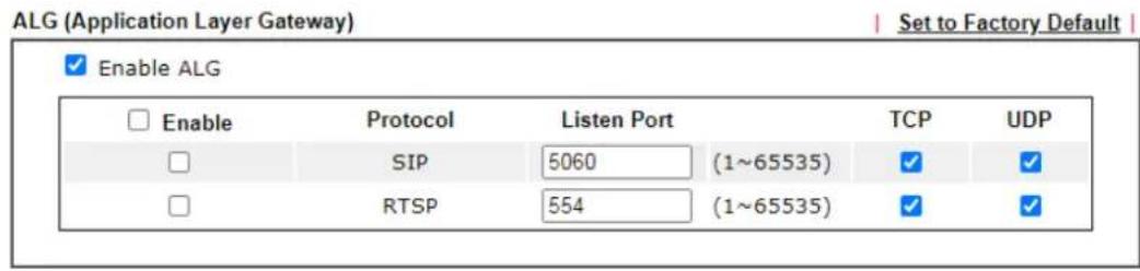
OK
Available settings are explained as follows:
| Item | Description |
| Enable ALG Check to enable | such function. |
| Listen Port Type a port number for SIP or RTSP protocol. | |
| TCP Check the box to make | correspond protocol message packet from TCP transmit and receive via NAT. |
| UDP Check the box to make | correspond protocol message packet from UDP transmit and receive via NAT. |
II-5 Applications
Dynamic DNS
Most ISPs assigns dynamic WAN IP addresses to their customers. Dynamic IP addresses presents challenges to users who would like to accept remote connections to their LANs from the Internet, as service could be disrupted due to the IP address changing without notice. By setting up service with a Dynamic DNS (DDNS) provider, and configuring Dynamic DNS updates on the Vigor router, you can have reliable access to your network by means of an easy-to-remember domain address that resolves to the most current WAN IP address.
The Vigor router supports a wide range of DDNS providers, such as DynDNS, No-IP.com, DtDNS, and ChangeIP. Please contact the DDNS provider of your choice to set up service before configuring DDNS on the router.
LAN DNS / DNS Forwarding
LAN DNS allows the network administrator to override standard DNS resolutions for selecting domain addresses. The router will respond to queries on matched domain addresses with custom IP addresses.
DNS Forwarding allows the network administrator to forward DNS queries to different DNS servers based on the domain name.
LAN DNS and DNS Forwarding only affect DNS queries that are sent to the WAN through the router. DNS queries that are directed to a DNS server on the LAN will not be intercepted by the router.
Schedule
The Vigor router has a built-in clock which can update itself manually or automatically by means of Network Time Protocols (NTP). As a result, you can not only schedule the router to dialup to the Internet at a specified time, but also restrict Internet access to certain hours so that users can connect to the Internet only during certain hours, say, business hours. The schedule is also applicable to other functions.
RADIUS/TACACS+
Remote Authentication Dial-In User Service (RADIUS) is a security authentication client/server protocol that supports authentication, authorization and accounting, which is widely used by Internet service providers. It is the most common method of authenticating and authorizing dial-up and tunneled network users.
The built-in RADIUS client feature enables the router to assist the remote dial-in user or a wireless station and the RADIUS server in performing mutual authentication. It enables centralized remote access authentication for network management.
LDAP /Active Directory Setup
Lightweight Directory Access Protocol (LDAP) is a communication protocol for using in TCP/IP network. It defines the methods to access distributing directory server by clients, work on directory and share the information in the directory by clients. The LDAP standard is established by the work team of Internet Engineering Task Force (IETF).
As the name described, LDAP is designed as an effect way to access directory service without the complexity of other directory service protocols. For LDAP is defined to perform, inquire and modify the information within the directory, and acquire the data in the directory securely, therefore users can apply LDAP to search or list the directory object, inquire or manage the active directory.
UPnP
The Vigor supports UPnP (Universal Plug and Play), which is a suite of network protocols that simplifies network configuration. Applications and network devices on the LAN, that support UPnP, may request the router to modify its settings to allow NAT Traversal, so that WAN hosts can connect to them directly.
Examples of applications and devices that support UPnP include file-sharing applications such as uTorrent, Vuze and eMule, gaming consoles such as the Sony PlayStations 3 and 4 Xbox 360 and Xbox One, media streaming applications such as Plex and XBMC, and messaging and calling applications such as Skype. To find out if a certain application or network device supports or requires UPnP, please consult its user manual or check with its vendor.
Wake on LAN
Using the Wake on LAN (WoL) feature, LAN clients that support WoL can be powered on or resume from sleep over the network, without the need for physical access to the device.
In order for LAN clients to be able to woken from sleep or off states, the network interface card must be configured to monitor Wake-on-LAN messages. Consult the documentation of the LAN client for details on setting up its network interface for Wake on LAN.
Web User Interface
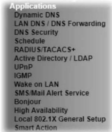
II-5-1 Dynamic DNS
Enable the Function and Add a Dynamic DNS Account
To begin configuring Dynamic DNS, from the main menu, navigate to Applications, and select Dynamic DNS. The Dynamic DNS main configuration screen appears:
Applications >> Dynamic DNS Setup
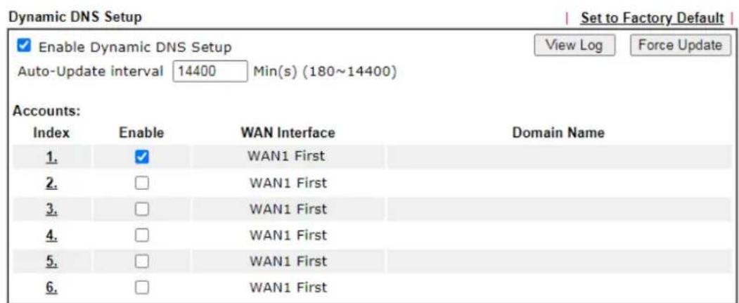

Available settings are explained as follows:
| Item | Description |
| Enable Dynamic DNS Setup | Select to enable DDNS function. |
| Set to Factory Default Click | to clear all profiles to factory settings. |
| View Log | Select to display the most recent DDNS update messages. |
| Force Update | Click to connect immediately to DDNS servers to update IP address information. |
| Auto-Update interval | The frequency, in minutes, at which the router connects to DDNS servers to update IP address information. |
| Index Click to bring up the configuration page of the DDNS profile. | |
| Enable Check the box to enable such account. | |
| WAN Interface | Shows the WAN interface associated with the DDNS profile. |
| Domain Name Shows the domain name with which the profile is associated. | |
After clicking on the index number, the detail configuration screen for the DDNS profile appears:
Applications >> Dynamic DNS Setup >> Dynamic DNS Account Setup
Index : 1
![Enable Dynamic DNS Account WAN Interface Service Provider Service Type Domain Name Login Name Password □ Wildcards □ Backup MX Mail Extender Determine WAN IP Let's Encrypt certificate Status Auto Renew WAN 1 First dyn.com (www.dyn.com) Dynamic faeallen3910 drayddns.com Max: 64 characters Max: 64 characters Max: 63 characters WAN IP Signed [Valid To: Oct 20 16:59:58 2022 GMT+08:00]](/content/2026/05/813922/images/9d931043409a79cc67dd19bb4a6c54e3501005e216f3317f7ddc4e3043fa15c6.jpg)
Note:
- The Create function of Let's Encrypt certificate works only when the current profile has been stored.
- WAN IP must be public IP when create Let's Encrypt certificate.
OK Clear Cancel
If User-Defined is specified as the service provider, the web page will be changed slightly as follows:
Index:1
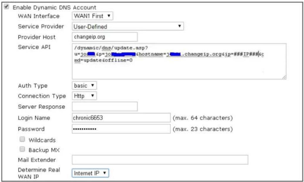
OK
Clear
Cancel
Available settings are explained as follows:
| Item | Description |
| Enable Dynamic DNS Account | Select to enable this DDNS profile. |
| WAN Interface | Select the WAN interface to monitor for IP address changes.WANx First - The specified WAN interface will be examined first. If it is online, its IP address will be used in the DDNS update.WANx Only - Only the specified WAN interface will be examined. If the WAN interface is online, its IP address will be used in the DDNS update. Otherwise no update will be performed for this DDNS profile. |
| Service Provider | Select the DDNS provider. If your DDNS provider is not listed, selectUser-Definedand manually configure the profile.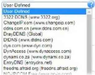 Provider Host - Enter the IP address or the domain name of the host which provides related service.Note that such option is available when Customized is selected as Service Provider.Service API - Enter the API information obtained from DDNS server.Note that such option is available when Customized isselected as Service Provider.(e.g:/dynamic/ dns/ update.asp?u=j0***&p=j0*******&hostname=j****.changeip.org&ip=###IP###&cmd=update&offline=0)Auth Type- Two types can be used for authentication.Basic-Username and password defined later can be shown from the packets captured.URL-Username and password defined later can be shown in URL.(e.g., http://ns1.vigordns.com/ ddns.php?username=xxxx&password=xxxx&domain=xxxx.vigordns.com)Note that such option is available when Customized is selected as Service Provider.Connection Type- There are two connection types (HTTP and HTTPS) to be specified. Note that such option is available when Customized is selected as Service Provider.Server Response- Type any text that you want to receive from the DDNS server.Note that such option is available when Customized is selected as Service Provider.If other service provider is selected, you have to configure Service Type, Domain Name, Login Name and Password.Service Type- Select the service type that matches that of your DynDNS account. If you are unsure which service type to select, try Dynamic first. This options is applicable to DynDNS only.Domain Name- The domain and subdomain to be updated. Provider Host - Enter the IP address or the domain name of the host which provides related service.Note that such option is available when Customized is selected as Service Provider.Service API - Enter the API information obtained from DDNS server.Note that such option is available when Customized isselected as Service Provider.(e.g:/dynamic/ dns/ update.asp?u=j0***&p=j0*******&hostname=j****.changeip.org&ip=###IP###&cmd=update&offline=0)Auth Type- Two types can be used for authentication.Basic-Username and password defined later can be shown from the packets captured.URL-Username and password defined later can be shown in URL.(e.g., http://ns1.vigordns.com/ ddns.php?username=xxxx&password=xxxx&domain=xxxx.vigordns.com)Note that such option is available when Customized is selected as Service Provider.Connection Type- There are two connection types (HTTP and HTTPS) to be specified. Note that such option is available when Customized is selected as Service Provider.Server Response- Type any text that you want to receive from the DDNS server.Note that such option is available when Customized is selected as Service Provider.If other service provider is selected, you have to configure Service Type, Domain Name, Login Name and Password.Service Type- Select the service type that matches that of your DynDNS account. If you are unsure which service type to select, try Dynamic first. This options is applicable to DynDNS only.Domain Name- The domain and subdomain to be updated. |
| Login Name The login name of the DDNS account. | |
| Password The password of the DDNS account. | |
| Wildcard and Backup MX The Wildcard and Backup MX (Mail Exchange) features are not supported for all Dynamic DNS providers. You could get more detailed information from their websites. | |
| Mail Extender If the mail server is defined with another name, please enter the name in this area. Such mail server will be used as backup mail exchange. | |
| Determine WAN IP | If a Vigor router is installed behind any NAT router, you can enable such function to locate the real WAN IP.When the WAN IP used by Vigor router is private IP, this function can detect the public IP used by the NAT router and use the detected IP address for DDNS update.There are two methods offered for you to choose:WAN IP- The IP address of the router's WAN interface will be used.Internet IP- The real public IP address will be used.Select this option if the IP address assigned to the router's WAN interface is not the actual external IP address. |
| Let's Encrypt certificate Create - Click it to generate a certificate issued by Let's Encrypt for applying to such DDNS account.Auto Renew- Check the box to make the system update the | |
| certificate automatically. | |
Click OK to save changes, Clear to clear all settings, or Cancel to discard changes and return to the main DDNS screen.
DrayDDNS Settings
DrayDDNS, a new DDNS service developed by DrayTek, can record multiple WAN IP (IPv4) on single domain name. It is convenient for users to use and easily to set up. Each Vigor Router is available to register one domain name.
Choose DrayTek Global as the service provider, the web page will be displayed as follows:
Applications >> Dynamic DNS Setup >> Dynamic DNS Account Setup
Index : 1
![Enable Dynamic DNS Account Service Provider DrayDDNS (Global) View Log Status [Status:Activated][Provider:DT-DDNS] [Start Date:2022-05-18 Expire Date:2023-05-18] Domain Name vivian3910 drayddns.com Sync domain Determine WAN IP WAN IP IPv4 IPv6 WAN Interfaces WAN1 WAN3 WAN4 WAN5 WAN6 WAN7 WAN8 Alias IP in Service Status Setup WAN 3 Only Connection Type Http Let's Encrypt certificate Status Signed [Valid To: Feb 18 15:55:04 2023 GMT+08:00] Auto Renew](/content/2026/05/813922/images/da53d35522ba2bc135cc710cfc0163f45a1fdb79ea010c4cf5c0aa04964af37b.jpg)
Note:
- The Create function of Let's Encrypt certificate works only when the current profile has been stored.

Available settings are explained as follows:
| Item | Description |
| Enable Dynamic DNS Account | Check this box to enable the current account. If you did check the box, you will see a check mark appeared on the Active column of the previous web page in step 2). |
| Service Provider | Choose DrayTek Global as the service provider. |
| Status Display if the license is activtaed or not. | |
| Domain Name The domain and subdomain to be updated. | |
| Determine WAN IP | If a Vigor router is installed behind any NAT router, you can enable such function to locate the real WAN IP.When the WAN IP used by Vigor router is private IP, this function can detect the public IP used by the NAT router and use the detected IP address for DDNS update.There are two methods offered for you to choose:WAN IP - If it is selected and the WAN IP of Vigor router is private, DDNS update will take place right away.Internet IP - If it is selected and the WAN IP of Vigor router is private, it will be converted to public IP before DDNS update takes place. |
| WAN Interfaces WANx | - While connecting, the router will use WANx as the channel for such account. |
| Let's Encrypt certificate | Auto Renew - Check the box to make the system update the certificate automatically. |
Disable the Function and Clear all Dynamic DNS Accounts
In the DDNS setup menu, uncheck Enable Dynamic DNS Setup, and push Clear All button to disable the function and clear all accounts from the router.
Delete a Dynamic DNS Account
In the DDNS setup menu, click the Index number you want to delete and then push Clear All button to delete the account.
DDNS updates take place when:
- The router is powered on or rebooted.
- The public IP address of any WAN interface changes.
- The online status of a WAN interface changes (going from online to offline or vice versa).
● The DDNS function is changed from disabled to enabled.
● A DDNS entry is modified and enabled. - The Auto-Update Interval has elapsed.
Procedures for Setting up a Dynamic DNS Entry
- Contact the dynamic DNS provider of your choice and have service set up. Most DDNS providers accept signups on their websites. Service could be provided free of charge or for a fee.
- Create a DDNS entry on the router by selecting the appropriate DDNS provider and enter the account information.
- Make sure that both the DDNS entry and the DDNS feature are enabled on the router.
- Click the View Log button on the DDNS main page to bring up the update log.
- Examine the update log to make sure the update was successful.
- If the update was not successful, verify the DDNS entry to make sure the settings are entered correctly.
II-5-2 LAN DNS / DNS Forwarding
The LAN DNS lets the network administrators host servers with privacy and security. When the network administrators of your office set up FTP, Mail or Web server inside LAN, you can specify specific private IP address (es) to correspondent servers. Thus, even the remote PC is adopting public DNS as the DNS server, the LAN DNS resolution on Vigor3910 Series will respond the specified private IP address.
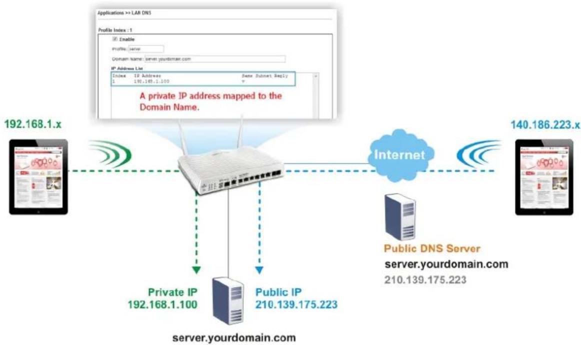
flowchart
graph TD
    A["Server"] -->|192.168.1.100| B["Router"]
    C["Public IP"] -->|210.139.175.223| B
    D["Internet"] -->|140.186.223.x| E["Server"]
    F["Public DNS Server"] -->|server.yourdomain.com 210.139.175.223| B
    G["Private IP"] -->|192.168.1.100| B
    H["IP Address List"] --> I["IP Address: 190.168.1.100"]
    J["Profile Index : 1"] --> K["Enable"]
    L["Domain Name: server.yourdomain.com"] --> M["IP Address List"]
    N["A private IP address mapped to the Domain Name."] --> B
To start configuring LAN DNS or DNS Forwarding, from the main menu, click Applications, followed by LAN DNS / DNS Forwarding.
Applications >> LAN DNS / DNS Forwarding

LAN DNS Resolution / Conditional DNS Forwarding
Set to Factory Default
| Index | Enable | Profile | Domain Name | Type | DNS Server |
| 1. | - | ||||
| 2. | - | ||||
| 3. | - | ||||
| 4. | - | ||||
| 5. | - | ||||
| 6. | - | ||||
| 7. | - | ||||
| 8. | - | ||||
| 9. | - | ||||
| 10. | - |
<< 1.10 | 11.20 | 21.30 | 31.40 | 41.50 | 51.60 | 61.70 | 71.80 | 81.90 | 91.100 | 101.110 | 111.120 >>
OK
Each item is explained as follows:
| Item | Description |
| Set to Factory Default Click | to clear all profiles to factory settings. |
| Index | Click to bring up the configuration page for the profile. |
| Enable Select to enable this | profile. |
| Profile Shows the name of the | profile. |
| Domain Name Shows the domain name configured for the profile. | |
| Type | Display the type (LAN DNS or DNS Forwarding) of the profile. |
| DNS Server DNS server to which DNS queries for the specified domain name will be forwarded. | |
To configure a LAN DNS profile, click on its index to bring up the configuration page.
Profile Index : 1
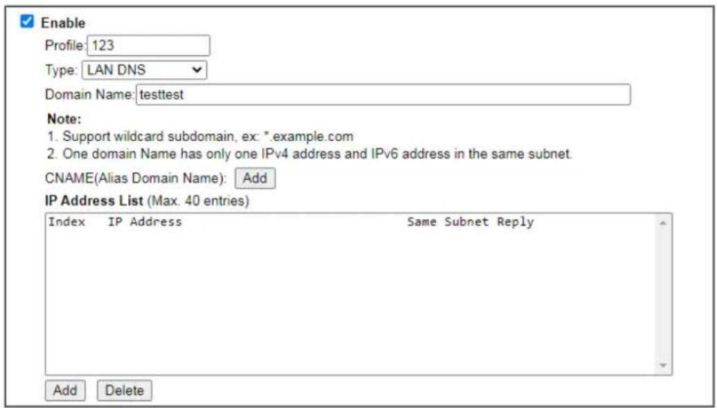

Available settings are explained as follows:
| Item | Description |
| Enable Select to enable this | profile. |
| Profile Enter a name to identify this profile. | Note: If you type a name here for LAN DNS and click OK to save the configuration, the name also will be applied to conditional DNS forwarding automatically. |
| Type Choose LAN DNS or LAN | Forwarding. |
| If LAN DNS is selected Domain Name - Enter the domain name for the router to look for in DNS queries to intercept and reply to. Wildcards in the form of asterisks (*) can be used to match a domain level. For example, *.draytek.com will match domain names such as www.draytek.com and ftp.draytek.com, whereas www.draytek.* will match domain names such as www.draytek.com and www.draytek.co.uk.CNAME - Click Add to add an domain name alias for the domain name. Click Delete next to an alias entry to delete it.IP Address List - The IP address listed here will be used for mapping with the domain name specified above. In general, one domain name maps with one IP address. If required, you can configure two IP addresses mapping with the same domain name.Add -Click Add to bring up the Add IP Address dialog box: | |
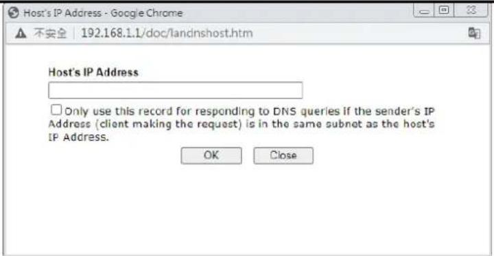 | |
| Host's IP Address - Enter the IP address to be returned in response to a DNS query for the configured domain names and aliases.Only use this record.... - Select to use this IP address only if the IP address of the source of the DNS query belongs to the same subnet as the host IP address entered above.After changes have been made, click OK to save and dismiss the dialog box, or Close to discard the changes and dismiss the dialog box.Delete-To delete an IP address, click on it and then click Delete. | |
| If DNS Forwarding is selected | Domain Name - Enter the domain name for the router to look for in DNS queries to intercept and reply to. Wildcards in the form of asterisks (*) can be used to match a domain level. For example, *.draytek.com will match domain names such as www.draytek.com and ftp.draytek.com, whereas www.draytek.* will match domain names such as www.draytek.com and www.draytek.co.uk.DNS Server IP Address - Enter the IP address of the DNS server you want to use for DNS forwarding. |
To save changes made to the LAN DNS profile, click OK. To clear the profile and restore the factory default blank values, click Clear.
II-5-3 DNS Security
Domain Name System Security Extensions (DNSSEC) protects against DNS-based attacks by authenticating DNS responses from DNS resolvers.
The DNS servers must support DNS security validation for the feature to function properly. To configure DNS security, from the main menu, click Applications, followed by DNS Security.
II-5-3-1 General Setup
All of WAN interfaces of Vigor router can be configured with DNS Security enabled respectively.
Applications >> DNS Security

DNS Security
| General Setup | Domain Diagnosis | Refresh | ||
| Interface | Enable | Primary DNS | Secondary DNS | Bogus DNS Reply |
| WAN1 | □ | --- | --- | Drop▼ |
| WAN3 | √ | 192.168.188.1 | 8.8.8.8 | Pass▼ |
| WAN4 | □ | --- | --- | Pass▼ |
| WAN5 | □ | --- | --- | Pass▼ |
| WAN6 | □ | --- | --- | Pass▼ |
| WAN7 | □ | --- | --- | Pass▼ |
| WAN8 | □ | --- | --- | Pass▼ |
Note:

The DNS server supports DNSSEC

The DNS server does not support DNSSEC, function may not work as expected even if it is enabled
OK
Available settings are explained as follows:
| Item | Description |
| Interface The WAN interface | name for which DNS security is to be configured. |
| Enable Select to enable DNS | security for this WAN Interface. |
| Primary DNS | Shows the primary DNS server IP address in effect for this WAN. |
| Secondary DNS Shows the secondary DNS server IP address in effect for this WAN. | |
| Bogus DNS Reply | Show action to be taken for DNS responses that fail authentication. Choose Pass or Drop.Pass - Pass DNS result.Drop - Do not pass DNS result. |
Press OK to save changes.
II-5-3-2 Domain Diagnose
While using the Domain Diagnose feature, you can check to see if the router's DNS security function is working properly, or whether a given domain is secured by DNS security. Note that DNS Security has to be first enabled or the test results would not be meaningful.
Application >> DNS Security

DNS Security
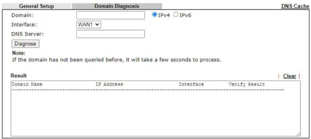
Available settings are explained as follows:
| Item | Description |
| Domain Enter domain address to be diagnosed.Select the type of IP address to be looked up.IPv4 - looks up A records.IPv6 - looks up AAAA records. | |
| Interface Select the WAN port to be used for the lookup. | |
| DNS Server | Enter the IPv4 address of the DNS server to be used for the lookup. |
| Diagnose Click to begin DNS lookup. | |
| Result | The history of domain diagnosis is shown in the Result panel. |
II-5-4 Schedule
Time schedules can be created and used with router features that support them, so that those features can be turned on and off automatically at preconfigured times.
Applications >> Schedule
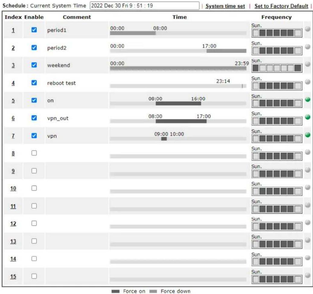
bar
| Index | Enable | Comment | Time | Frequency | | :--- | :--- | :--- | :--- | :--- | | 1 | ✓ | period1 | 00:00 - 08:00 | Sun. | | 2 | ✓ | period2 | 00:00 - 17:00 | Sun. | | 3 | ✓ | weekend | 00:00 - 23:59 | Sun. | | 4 | ✓ | reboot test | 23:14 | Sun. | | 5 | ✓ | on | 08:00 - 16:00 | Sun. | | 6 | ✓ | vpn_out | 08:00 - 17:00 | Sun. | | 7 | ✓ | vpn | 09:00 - 10:00 | Sun. | | 8 | □ | | | Sun. | | 9 | □ | | | Sun. | | 10 | □ | | | Sun. | | 11 | □ | | | Sun. | | 12 | □ | | | Sun. | | 13 | □ | | | Sun. | | 14 | □ | | | Sun. | | 15 | □ | | | Sun. | Schedule: Current System Time; Date: Fri 9:51:19; System time set; Set to Factory Default; Frequency; Legend: Force on, Force down.Available settings are explained as follows:
| Item | Description |
| Current System Time Shows | the current time of the router. |
| System time set | Click to navigate to System Maintenance >> Time and Date to set the system time and date. |
| Set to Factory Default Reset | all schedules to factory default values. |
| Index Shows the index number of the schedule entry. | |
| Enable Select to enable the schedule; clear to disable it. | |
| Comment Shows the name given to the schedule. | |
| Time Shows the start and end times of the schedule. The time interval of the schedule is indicated in dark grey. | |
| Frequency Shows the days of the week configured for the schedule.Selected days are shown in dark grey.- If it lights in green, it means such schedule is active. | |
To configure a schedule, click on its index to bring up the settings page.
Applications >> Schedule
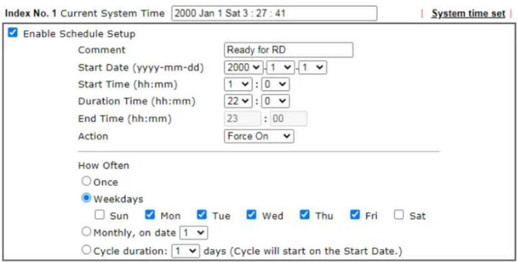
Note:
Comment can only contain A-Z a-z 0-9, . {} - _ ( ) ^ \$ ! \~ ' |

Available settings are explained as follows:
| Item | Description |
| Enable Schedule Setup Select to enable the schedule; clear to disable it. | |
| Comment Name to identify this schedule entry. | |
| Start Date (yyyy-mm-dd) The date when the entry comes into effect. | |
| Start Time (hh:mm) | The time when the schedule is triggered. See the How Often setting below for details. |
| Duration Time (hh:mm) How long the action lasts when the scheduled is triggered. | |
| End Time (hh:mm) It will be calculated automatically when Start Time and Duration Time are configured well. | |
| Action Action to take when the schedule is triggered. | |
| How Often How frequently the schedule is triggered. | |
| ● Monthly, on date - The router will only execute the action applied such schedule on the date (1 to 28) of a month. ● Cycle duration - Type a number as cycle duration. Then, any action applied such schedule will be executed per several days. For example, “3” is selected as cycle duration. That means, the action applied such schedule will be executed every three days since the date defined on the Start Date. | |
To save changes made to the Schedule, click OK. To clear the schedule and restore the factory default blank values, click Clear. To cancel the changes and return to the main Schedule page, click Cancel.
Example
Suppose you want to control the PPPoE Internet access connection to be always on (Force On) from 9:00 to 18:00 for whole week. Other time the Internet access connection should be disconnected (Force Down).
Office
Hour:
(Force On)


Mon - Sun 9:00 am to 6:00 pm
- Make sure the PPPoE connection and Time Setup is working properly.
- Configure the PPPoE always on from 9:00 to 18:00 for whole week.
- Configure the Force Down from 18:00 to next day 9:00 for whole week.
- Assign these two profiles to the PPPoE Internet access profile. Now, the PPPoE Internet connection will follow the schedule order to perform Force On or Force Down action according to the time plan that has been pre-defined in the schedule profiles.
II-5-5 RADIUS/TACACS+
Remote Authentication Dial-In User Service (RADIUS) is a security authentication client/server protocol that supports authentication, authorization, and accounting, which is widely used in enterprise networks. It is the most common authentication method to manage the clients' access to the wireless network, the Internet and the VPN.
The router supports external TACACS+ and internal and external RADIUS servers for user authentication. To configure TACACS+ or RADIUS servers, from the Main Menu select Applications >> RADIUS/TACACS+.
II-5-5-1 External RADIUS
The built-in RADIUS client feature enables the router to assist the remote dial-in user or a wireless station and the RADIUS server in performing mutual authentication. It enables centralized remote access authentication for network management.
Vigor router can be operated as a RADIUS client. This web page is used to configure settings for external RADIUS server. Then LAN users of Vigor router will be authenticated and accounted by such server for network application.
Select External RADIUS to configure the router to use an external RADIUS server for user authentication.
Applications >> RADIUS/TACACS+
| External RADIUS | Internal RADIUS | External TACACS+ | ||
| Index | Enable | Comments | Primary Server | Secondary Server |
| 1. | ||||
| 2. | ||||
| 3. | ||||
| 4. | ||||
Default Profile Profile 1 RADIUS Request Interval 2 sec (2\~30)

| RADIUS Server Status Log | |||
| Profile | 1▼ | | Refresh | | Clear | |
| Item | Description |
| Enable Select to enable the | profile. |
| Comment Displays the comment of the profile. | |
| Primary Server Displays the | IP address of the primary server. |
| Secondary Server Display the | IP address of the secondary server. |
| Default Profile Select one of | the profiles as the default profile for user authentication. |
| RADIUS Request Interval Set | a timeout value for the router waiting for a response from the RADIUS server. If no response, Vigor router will send the authentication request again. |
RADIUS Server Status Log Display the record of current status of RADIUS server.
Click any index number to open the following page. It is used to configure settings for external RADIUS server. Then users of the Vigor router will be authenticated by this server for the network application.
Applications >> RADIUS/TACACS+ >> Profile 1
Enable this profile
Enable Accounting
Comments:
Primary Server
Primary Server
Secret
Authentication Port
Accounting Port
Disconnect Message Port
Interim Update Interval
Retry
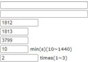
Secondary Server
Secondary Server
Secret
Authentication Port
Accounting Port
Disconnect Message Port
Interim Update Interval
Retry
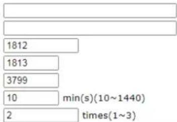
Note:
If RADIUS server has specified Interim Update Interval value(Acct-Interim-Interval), Vigor Router will follow the interval that the RADIUS server provides and ignore the Interim Update Interval setting here.

Available settings are explained as follows:
| Item | Description |
| Enable this profile Check to | enable RADIUS client profile.Comment - Enter a brief description for this profile. |
| Enable Accounting After checking it, Vigor router supports the accounting feature (available seconds for using, quantity of RX/ TX data) for external RADIUS server. Any client tries to access the Internet shall be authenticated and accounted by an external RADIUS server.Accounting Port -The UDP port number that the RADIUS server is using. The default value is 1813, based on RFC 2138.Disconnect Message Port - Set a port number for listening the RADIUS disconnection message.Interim Update Interval - Set a time interval for sending the accounting request to the RADIUS server. | |
Applications >> RADIUS/TACACS-> >> Profile 1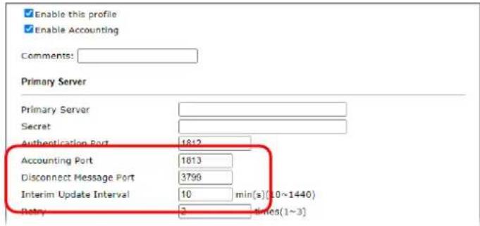 | |
| Primary Server Primary Server | - Enter the IP address of RADIUS server.Secret - The RADIUS server and client share a secret that is used to authenticate the messages sent between them. Both sides must be configured to use the same shared secret. The maximum length of the shared secret you can set is 36 characters.Authentication Port - The UDP port number that the RADIUS server is using. The default value is 1812, based on RFC 2138.Retry - Set the number of attempts to perform reconnection with RADIUS server. If the connection (with the Primary Server) still fails, stop the connection attempt and begin to make connection with the secondary server. |
| Secondary Server Secondary Server | - Enter the IP address of RADIUS server.Secret - The RADIUS server and client share a secret that is used to authenticate the messages sent between them. Both sides must be configured to use the same shared secret. The maximum length of the shared secret you can set is 36 characters.Authentication Port - The UDP port number that the RADIUS server is using. The default value is 1812, based on RFC 2138.Retry - Set the numberof attempts to perform reconnection. If the connection (with the Secondary Server) still fails, stop the connection attempt. The client authentication would be determined as "failed". |
To save changes on the page, click OK. To discard changes, click Cancel. To reset all settings to blank, click Clear.
II-5-5-2 Internal RADIUS
Except for being a built-in RADIUS client, Vigor router also can be operated as a RADIUS server which performs security authentication by itself. This page is used to configure settings for internal RADIUS server. Then users of Vigor router will be authenticated by Vigor router directly.
Select Internal RADIUS to configure the router's built-in RADIUS server.
Applications >> RADIUS/TACACS+
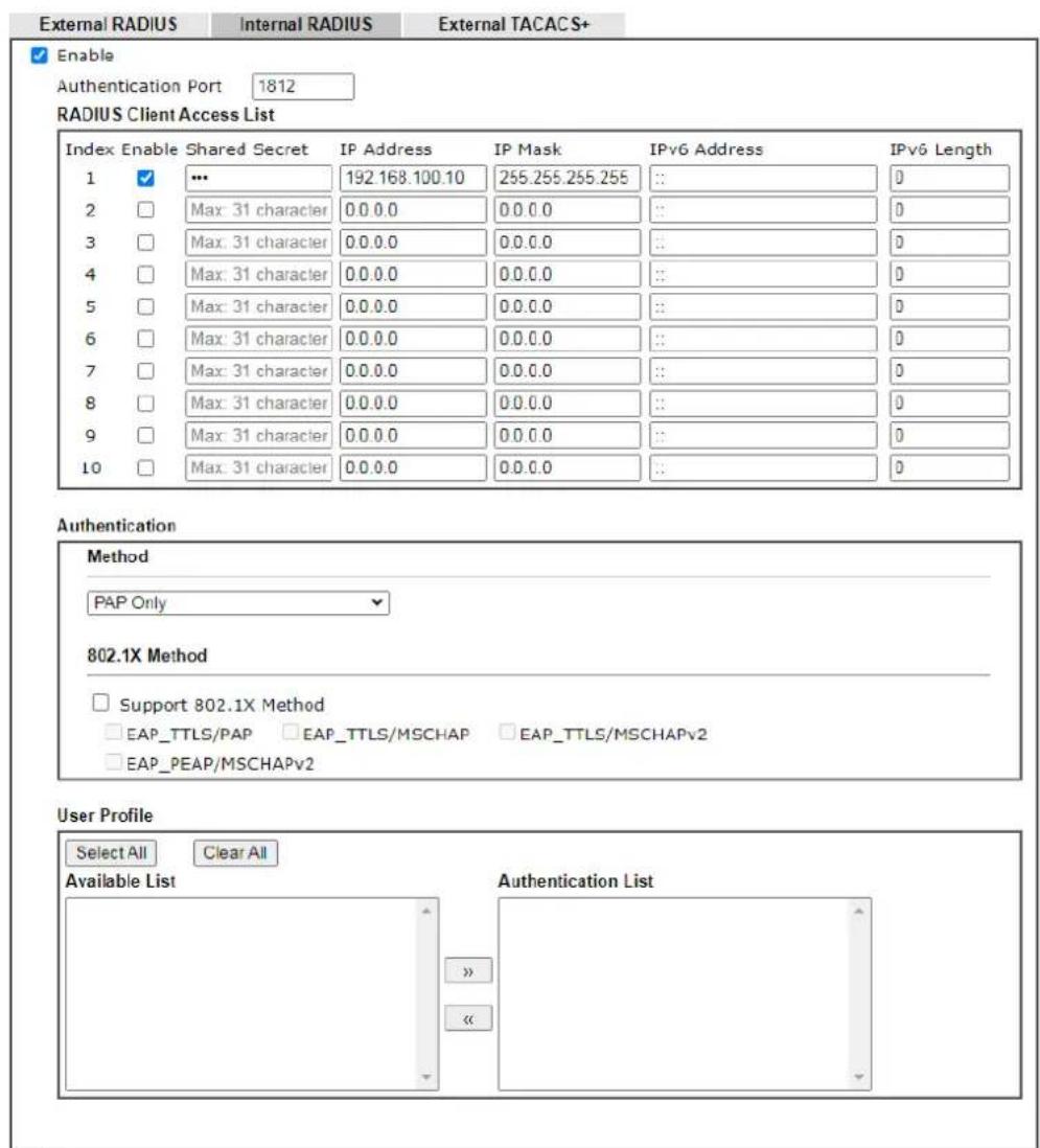
Note:
1. Only the user profiles which is enabled in User Management >> User Profile will be listed here, and it shows in the System Maintenance >> Internal Service User List.
2.RADIUS Client Access List is first match.

Available settings are explained as follows:
| Item | Description |
| Enable Select to enable the | router's internal RADIUS server. |
| Authentication Port The UDP port for authentication message. | |
| RADIUS Client Access List | Only clients that meet the criteria configured in the access list are allowed to access the RADIUS server. Index - The index number of the client entry. Enable - Select to enable this client entry. Shared Secret - A text string that is known to both the router's RADIUS server and the RADIUS client that is used to authenticate messages sent between them. Maximum length is 36 characters. IP Address - Enter the base address of the IP block.IP Mask - Enter the IP mask to configure the size of the IP block.IPv6 Address - Enter the base address of the IPv6 block.IPv6 Length - Enter the prefix length of the IPv6 block. |
| Authentication Configures the authentication settings.Specify the way to authenticate the client.PAP - Only the Password Authentication Protocol will be used to validate users.PAP/CHAP/MS-CHAP/MS-CHAPv2 - PAP, CHAP(Challenge-Handshake Authentication Protocol), and Microsoft versions of CHAP can be used to validate users.Support 802.1X Method - The built in RADIUS server offered by Vigor router can act as the AAA server. Select to enable 802.1X support. | |
| User Profile | During the process of security authentication, user account and user password will be required for identity authentication. Before configuring such page, create at least one user profile in User Management>>User Profile first.Select All - Click to move all user profiles under the Available List to the Authentication List.Clear All- Click to remove all user profiles from the Authentication List.Available List - User profiles (created in User Management >> User Profile) that have not been added to the authentication list.Authentication List - User profiles (created in User Management >> User Profile) that have been added to the authentication list. Users can log in using these profiles. |
To add a User Profile to the RADIUS server, select it under Available List, then click the >> button. To remove a User Profile from the RADIUS server, select it under Selected Authentication List, then click the << button.
To save changes on the page, click OK. To discard changes, click Cancel. To reset all settings to blank, click Clear.
II-5-5-3 External TACACS+
It means Terminal Access Controller Access-Control System Plus. It works like RADIUS does. Click the External TACACS+ to open the following page:
Applications >> RADIUS/TACACS+
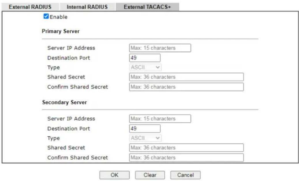
Available settings are explained as follows:
| Item | Description |
| Enable Select to enable the | use of an external TACACS+ server. |
| Primary Server / Secondary Server | Two external TACACS+ servers are allowed to set in this page.The secondary TACACS+ server will be used as a backup server when the primary TACACS+ server is down. |
| Server IP Address The IP address of the TACACS+ server. | |
| Destination Port | The port used by the TACACS+ server. Port 49 is most common. |
| Shared Secret A text string that is known to both the TACACS+ server and client (the router) that is used to authenticate messages sent between them. Maximum length is 36 characters. | |
| Confirm Shared Secret Enter the shared secret again for verification. | |
To save changes on the page, click OK. To discard changes, click Cancel. To reset all settings to blank, click Clear.
II-5-6 Active Directory/ LDAP
Lightweight Directory Access Protocol (LDAP) is an industry-standard protocol for maintaining and accessing directory information on a network. When used in conjunction with a Vigor router, LDAP can be used to authenticate VPN connection attempts.
Active Directory (AD) is a directory service from Microsoft that supports LDAP queries.
To configure Active Directory or LDAP settings, from the Main Menu select Applications >> Active Directory /LDAP.
II-5-6-1 General Setup
To configure the settings for the LDAP server, select General Setup.
Applications >> Active Directory / LDAP
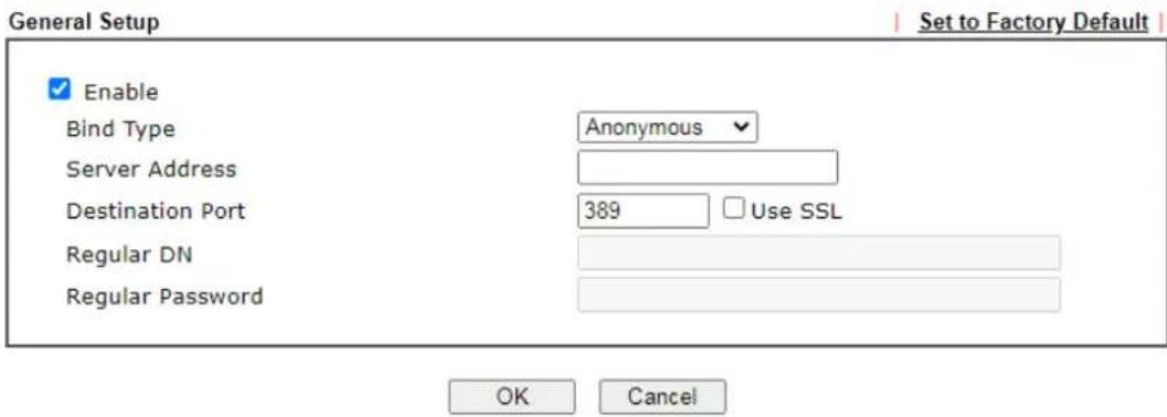
Active Directory / LDAP Profiles
| Index | Name | Distinguished Name |
| 1. | ||
| 2. | ||
| 3. | ||
| 4. | ||
| 5. | ||
| 6. | ||
| 7. | ||
| 8. |
Available settings are explained as follows:
| Item | Description |
| Enable Select to enable LDAP client. | If enabled, the LDAP profiles will be available for configuration. |
| Bind Type Select from one | of 3 bind types:Simple Mode - Initiate bind operation (authentication) without performing user search. This mode can be used when all users belong to the same branch in the LDAP structure.Anonymous - Bind anonymously, without supplying the distinguished name (DN) and password, and perform usersearch. This mode can be used when not all users belong to the same branch and the server allows anonymous searches.● Regular Mode - Same as Anonymous mode, except that the DN and password are sent to the server. This mode can be used when not all users belong to the same branch and the server does not allow anonymous searches.For the regular mode, you'll need to Enter the Regular DN and Regular Password. |
| Server Address The network address of the LDAP server. | |
| Destination Port The network port that the LDAP server listens on. The default ports are 389 for unsecured connections and 636 for LDAPS (LDAP over SSL) connections. | |
| Use SSL Select to use Secure Sockets Layer (SSL) for LDAP traffic. | |
| Regular DN | Enter the LDAP Distinguished Name for authentication if Bind Type is set to Regular Mode. |
| Regular Password | Enter the LDAP Password for authentication if Bind Type is set to Regular Mode. |
| Active Directory / LDAP Profiles | Up to 8 LDAP profiles can be created. These profiles would be used with User Management for different purposes in management. |
To save changes on the page, select OK; to discard changes, select Cancel.
II-5-6-2 Active Directory / LDAP Profiles
Up to 8 LDAP profiles can be created. These profiles would be used with User Management for different purposes in management.
To configure an LDAP profile, click on its index to show the following settings page.
Applications >> Active Directory /LDAP>>Server Profiles
Index No. 1
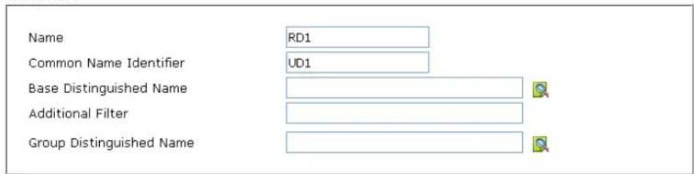
Note:
Please type in your additional filter for BaseDN search request. For example, "gidNumber=500" for OpenLDAP, and "msNPAIowDialin=TRUE" for AD.

Available settings are explained as follows:
| Item | Description |
| Name Name that identifies | this profile. Maximum length is 19 characters. |
| Common Name Identifier | The common name attribute, which is typically “cn” in most LDAP configurations. |
| Base Distinguished Name | The starting point of user search in the LDAP directory, for example, dc=draytek,dc=com. - click this icon to display a list of valid DNs in the LDAP directory. |
| Additional Filter Additional filter to be applied to the search request to identify eligible users. For example, - “OpenLDAP: (gidNumber=500)” Here group ID 500 is the group of dial-in users. - “ActiveDirectory: (msNPAIlowDialin=TRUE)” The msNPAIlowDialin attribute indicates that the user has permission to dial in remotely. | |
| Group Distinguished Name | The base DN of the tree in the LDAP directory that contains groups, for example, ou=groups,dc=draytek,dc=com. - click this icon to display a list of valid DNs in the LDAP directory. |
To save changes on the page, select OK; to discard changes, select Cancel.
II-5-7 UPnP
To configure UPnP settings, from the Main Menu select Applications >> UPnP.
Applications >> UPnP
UPnP

Note:
- To allow NAT pass-through to a UPnP enabled client the connection control service must also be enabled.
- CAUTION: due to vulnerabilities CVE-2020-12695, UPnP is not considered safe to use. Use it at your own risk.
OK Clear Cancel
Available settings are explained as follows:
| Item | Description |
| Enable UPNP Service Select | to enable UPnP. |
| Default WAN Select the WAN | port on which ports will be opened in response to UPnP commands. |
| Enable Connection Control Service | Select to enable the connection control service. |
| Enable Connection Status Service | Select to enable the connection status service. |
To save changes on the page, select OK; to discard changes, select Cancel; to revert all settings to the factory default, select Clear.
The reminder as regards concern about Firewall and UPnP:
Can't work with Firewall Software
Enabling firewall applications on your PC may cause the UPnP function not working properly. This is because these applications will block the accessing ability of some network ports.
Security Considerations
Activating UPnP allows any application or network devices to open ports on the WAN side to allow connections to the LAN, which could compromise network security. Also if UPnP applications or network devices malfunction or terminate abnormally, the opened ports may remain open indefinitely, and thus increasing the chance of it getting exploited by malicious parties.
If you do not have applications or network devices which requires UPnP, you are advised to disable UPnP.

Info
UPnP is required for some applications such as PPS, Skype, eMule...and etc. If you are not familiar with UPnP, it is suggested to turn off this function for security.
II-5-8 IGMP
Internet Group Management Protocol (IGMP) is an IPv4 communication protocol for establishing multicast group memberships.
To configure IGMP settings, from the Main Menu select Applications >> IGMP.
II-5-8-1 General Setting
Applications >> IGMP
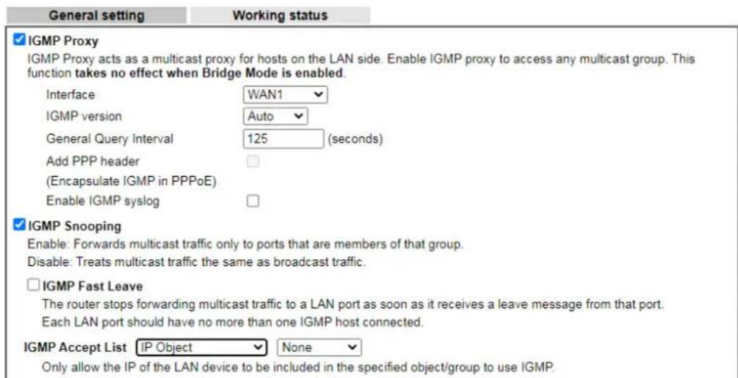

Available settings are explained as follows:
| Item | Description |
| IGMP Proxy Check this box to enable this function. The application of multicast will be executed through WAN / PVC/ VLAN port. In addition, such function is available in NAT mode. Interface - Specify an interface for packets passing through. IGMP version - At present, two versions (v2 and v3) are supported by Vigor router. Choose the correct version based on the IPTV service you subscribe. General Query Interval - Vigor router will periodically check which IP obtaining IPTV service by sending query. It might cause inconvenience for client. Therefore, set a suitable time (unit: second) as the query interval to limit the frequency of query sent by Vigor router. Add PPP header - Check this box if the interface type for IGMP is PPPoE. It depends on the specifications regulated by each ISP. If you have no idea to enable or disable, simply contact your ISP providers. Enable IGMP syslog - Check the box to store the IGMP status ontot Syslog. | |
| IGMP Snooping Select to enable IGMP Snooping so that multicast traffic are forwarded to IGMP clients that have joined a multicast group. | |
| IGMP Fast Leave This option is shown only when IGMP Snooping is enabled.Select to enable IGMP Fast Leave.Normally when the router receives a “leave” message from an IGMP host, it will send a last member query message to see if there are still members within the multicast group.When Fast Leave is enabled, multicast for a group is immediately terminated when the last host in that group sends a “leave” message. | |
| IGMP Accept List Select IP Object or IP Group.Only the IP of the LAN device within the IP object / IP group will be allowed to use IGMP. | |
To save changes on the page, select OK; to discard changes, select Cancel.
II-5-8-2 Working Status
Displays a list of active multicast groups.
Applications >> IGMP
| General setting | Working status | ||||||
| Multicast Group Table | |||||||
| Index | Group ID | P2 | P4 | P9 | P10 | P11 | P12 |
IGMP Device Table
| Index | MAC Address | IP Address | Interface | IGMP Version |
Available settings are explained as follows:
| Item | Description |
| Refresh Click to reload the | Multicast Group Table with the latest information. |
| Index Index number of the multicast group. | |
| Group ID ID port of the multicast group, which is within the IP range reserved for IGMP, 224.0.0.0 through 239.255.255.254. | |
| P2 to P12 LAN ports that have IGMP hosts joined to this multicast group. | |
II-5-9 Wake on LAN
Using the Wake on LAN (WoL) feature, LAN clients that support WoL can be powered on or resume from sleep over the network, without the need for physical access to the device.
In order for LAN clients to be able to wake from sleep or off states, the network interface card must be configured to monitor Wake-on-LAN messages. Consult the documentation of the LAN client for details on setting up its network interface for Wake on LAN.
If you wish to be able to select the IP address of the Wake-on-LAN client, its MAC address must first be bound to a static IP address using the Bind IP to MAC function.
To configure Wake on LAN settings, from the Main Menu select Applications >> Wake on LAN.
Applications >> Wake on LAN
Wake on LAN
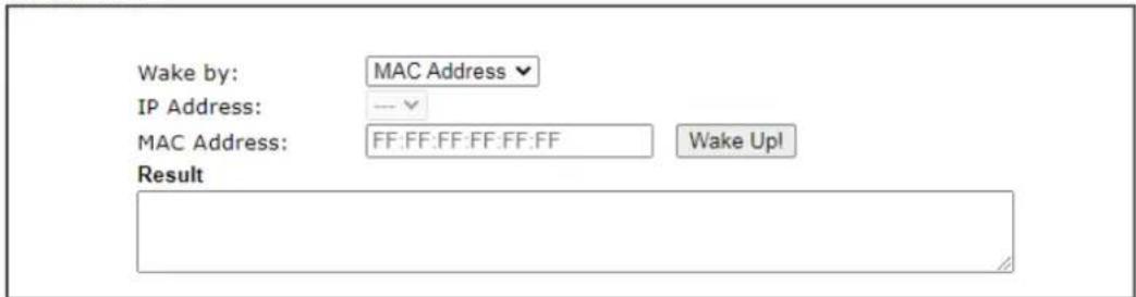
Note:
Wake on LAN integrates with Bind IP to MAC function; only bound PCs can wake up through IP.
Available settings are explained as follows:
| Item | Description |
| Wake by The type of address | of the LAN client to be woken up.If you choose Wake by MAC Address, you have to Enter the correct MAC address of the host in MAC Address boxes.If you choose Wake by IP Address, you have to choose the correct IP address. |
| IP Address The IP addresses | that have been configured in Firewall>>Bind IP to MAC will be shown in this drop down list.Select the IP address of the LAN client. |
| MAC Address Enter the MAC | address of the LAN client. |
| Wake Up Click to send Wake | -on-LAN message to the specified LAN client. |
| Result Result of the transmission of the Wake-on-LAN message. | |
II-5-10 SMS / Mail Alert Service
You can set up SMS or mail profiles for the router to send events or alerts to designated recipients. Up to 10 SMS profiles and 10 mail profiles can be configured.
II-5-10-1 SMS Alert
To configure SMS alert profiles, select the SMS Alert tab.
Applications >> SMS / Mail Alert Service
| SMS Alert | Mail Alert | Set to Factory Default | ||||||
| Index | Enable | SMS Provider | Recipient Number | Notify Profile | Schedule(1-15) | |||
| 1 | 1 - ??? | 1 - ??? | None | √ | None | √ | ||
| 2 | 1 - ??? | 1 - ??? | None | √ | None | √ | ||
| 3 | 1 - ??? | 1 - ??? | None | √ | None | √ | ||
| 4 | 1 - ??? | 1 - ??? | None | √ | None | √ | ||
| 5 | 1 - ??? | 1 - ??? | None | √ | None | √ | ||
| 6 | 1 - ??? | 1 - ??? | None | √ | None | √ | ||
| 7 | 1 - ??? | 1 - ??? | None | √ | None | √ | ||
| 8 | 1 - ??? | 1 - ??? | None | √ | None | √ | ||
| 9 | 1 - ??? | 1 - ??? | None | √ | None | √ | ||
| 10 | 1 - ??? | 1 - ??? | None | √ | None | √ | ||
Note:
All the SMS Alert profiles share the same "Sending Interval" setting if they use the same SMS Provider.

Available settings are explained as follows:
| Item | Description |
| Set to Factory Default Click | to clear all SMS alert profiles. |
| Enable Select the checkbox | to enable the profile. |
| SMS Provider Select the profile of the SMS provider to be used. To set up or modify SMS provider profiles, click the hyperlink SMS Provider to go to Objects Setting >> SMS/ Mail Service Object. | |
| Recipient Number Enter the recipient's SMS number. | |
| Notify Profile Select the notification profile to be used. To set up or modify notification object profiles, click the hyperlink Notify Profile to go to Objects Setting >> Notification Object. | |
| Schedule (1-15) | Enter up to 2 schedule profile indexes. To set up or modify schedule profiles, click the hyperlink Schedule(1-15) to go to Applications >> Schedule. |
After finishing all the settings here, please click OK to save the configuration.
II-5-10-2 Mail Alert
To configure mail alert profiles, select the SMS Alert tab.
Application >> SMS / Mail Alert Service
| SMS Alert | Mail Alert | Set to Factory Default | ||||
| Index | Enable | Mail Service | Mail Address | Notify Profile | Schedule(1-15) | |
| 1 | 1 - ??? √ | 1 - ??? √ | None √ | None √ | ||
| 2 | 1 - ??? √ | 1 - ??? √ | None √ | None √ | ||
| 3 | 1 - ??? √ | 1 - ??? √ | None √ | None √ | ||
| 4 | 1 - ??? √ | 1 - ??? √ | None √ | None √ | ||
| 5 | 1 - ??? √ | 1 - ??? √ | None √ | None √ | ||
| 6 | 1 - ??? √ | 1 - ??? √ | None √ | None √ | ||
| 7 | 1 - ??? √ | 1 - ??? √ | None √ | None √ | ||
| 8 | 1 - ??? √ | 1 - ??? √ | None √ | None √ | ||
| 9 | 1 - ??? √ | 1 - ??? √ | None √ | None √ | ||
| 10 | 1 - ??? √ | 1 - ??? √ | None √ | None √ | ||
Note:
All the Mail Alert profiles share the same "Sending Interval" setting if they use the same Mail Server.

Available settings are explained as follows:
| Item | Description |
| Set to Factory Default Click | to clear all mail alert profiles. |
| Enable Select the checkbox | to enable the profile. |
| Mail Service Select the profi | le of the mail provider to be used. To set up or modify a mail provider profile, click the hyperlink Mail Service to go to Objects Setting >> SMS/ Mail Service Object. |
| Mail Address Enter the recipient's email address. | |
| Notify Profile Select the not | ification profile to be used. To set up or modify a notification object profile, click the hyperlink Notify Profile to go to Objects Setting >> Notification Object. |
| Schedule (1-15) | Enter up to 2 schedule profile indexes. To set up or modify schedule profiles, click the hyperlink Schedule(1-15) to go to Applications >> Schedule. |
After finishing all the settings here, please click OK to save the configuration.
II-5-11 Bonjour
Bonjour is Apple's implementation of zero-configuration networking (Zeroconf), a technology that allows automatic discovery and configuration of network devices and services. Bonjour is built into OS X, and versions for Windows PCs can be downloaded without charge from Apple's website.
Without Bonjour, routers, computers, and other network peripherals would require manual configuration of network settings such as IP addresses and port numbers, which could be complex and cumbersome. By enabling Bonjour on the Vigor router, users only need to know the name of the router in order to set up connectivity between LAN devices, and the router and the peripherals that are connected to it.
To enable the Bonjour service, click Application>>Bonjour to open the following page. Check the box(es) of the server service(s) that you want to share to the LAN clients.
Available settings are explained as follows:
| Item | Description |
| Enable Bonjour Service Select to enable the Bonjour service on the router. The rest of the checkboxes will be enabled for selection when this checkbox has been selected. | |
| HTTP Server | Select to allow the router's HTTP server to be discovered via Bonjour. |
| Telnet Server Select to allow the router's telnet server to be discovered via Bonjour. | |
| SSH Server | Select to allow the router's SSH server to be discovered via Bonjour. |
Below shows an example for applying the bonjour feature that Vigor router can be used as the FTP server.
- Here, we use Firefox and DNSSD to discover the service in such case. Therefore, just ensure the Bonjour client program and DNSSD for Firefox have been installed on the computer.

- Open the web browse, Firefox. If Bonjour and DNSSD have been installed, you can open the web page (DNSSD) and see the following results.

DNSSD for Firefox
![Browser Configuration Options Diagnostic Information Interface Name Type Domain Service Info 2 DS1010Plus _http_tcp local Select a service on the left to view further details. 2 DS1010Plus(WebDAV) _http_tcp local 2 HP LaserJet 1300 _jpp_tcp local 2 tctseng-virtual-machine _udisks-sah_tcp local 2 tctseng-virtual-machine [00:0c:29.78:bc:24] _workstation_tcp local 2 tomkao-desktop [00:0c:29.25:09.5d] _workstation_tcp local](/content/2026/05/813922/images/649b521542967b99e0c954a5b8f1fc90a1ef99186a88e6de74aed899c990092a.jpg)
- Open System Maintenance>>Management. Type a name (e.g., DrayTek) as the Router Name and click OK.
| System Maintenance >> Management | ? |
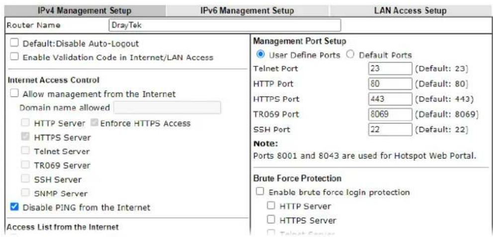
- Next, open Applications>>Bonjour. Check the service that you want to use via Bonjour.
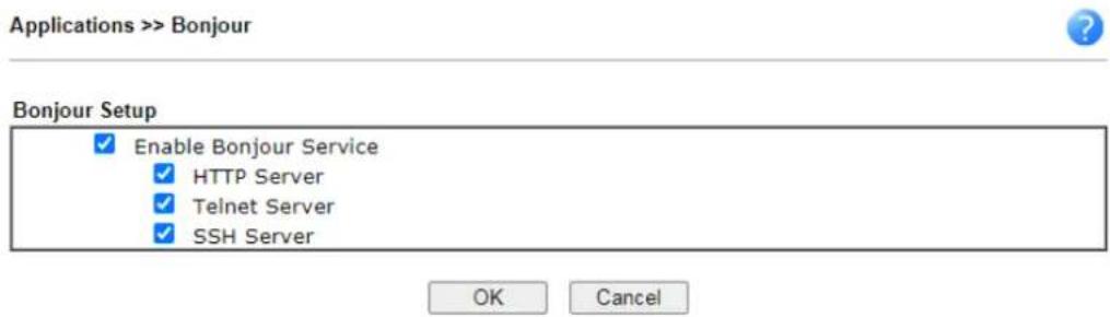
- Open the DNSSD page again. The available items will be changed as the follows. It means the Vigor router (based on Bonjour protocol) is ready to be used as a printer server, FTP server, SSH Server, Telnet Server, and HTTP Server.
DNSSD for Firefox
![Interface Name Type Domain Service Info 2 DS1010Plus _http_tcp. local Select a service on the left to view further details. 2 DS1010Plus(WebDAY) _http_tcp. local 2 HP LaserJet 1300 _pp_tcp. local 2 Vigor Router _ftp_tcp. local 2 Vigor Router _http_tcp. local 2 Vigor Router _printer_tcp. local 2 Vigor Router _ash_tcp. local 2 Vigor Router _telnet_tcp. local 2 tctseng-virtual-machine _udisks-ssh_tcp. local 2 tctseng-virtual-machine [00.0c:29:70:bc:24] _workstation_tcp. local 2 tomkao-desktop [00.0c:29:26:09:5d] _workstation_tcp. local](/content/2026/05/813922/images/967eaaf773842143cc29708de8414a34e3e092f87f3130bdd10fe7a16780168a.jpg)
- Now, any page or document can be printed out through Vigor router (installed with a printer).
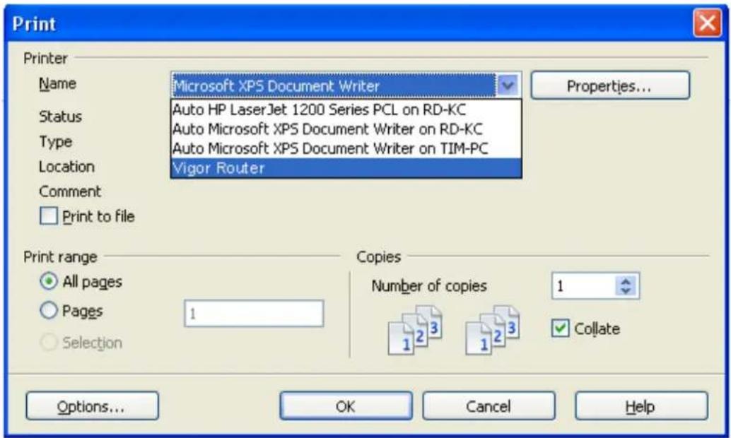
II-5-12 High Availability
The High Availability (HA) feature of the router provides redundancy of network resources, and reduces downtime in case of component failure. The level of sophistication of HA is determined by availability requirements and tolerance of system interruptions. Systems that provide near full-time availability typically have redundant hardware and software.
The HA of the Vigor3910 Series is designed to avoid single points-of-failure. When failures occur, the failover process transfers the network load handled by the failed component (the primary router) to the backup component (the secondary router), and the availability of network resources are preserved and partially failed transactions are recovered. In a matter of seconds the system returns to normal operation.
In order to set up High Availability, at least 2 DrayTek routers have to be configured in the following manner:
● Enable High Availability on both the primary and secondary routers.
- Set a high priority ID on the primary router, and a lower priority ID on the secondary router.
- Configure identical redundancy methods, group IDs, and authentication keys on both routers.
- Set the management interface of both routers to the same subnet.
- Enable virtual IP on both routers for each subnet in use. Make sure the virtual IPs are identical on both routers.
II-5-12-1 General Setup
Open Applications>>High Availability to bring up the configuration page to configure High Availability.
Applications >> High Availability

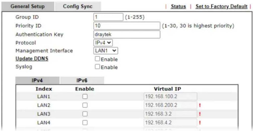
Available settings are explained as follows:
| Item | Description |
| Enable High Abailability Select to enable HA function. | |
| Redundancy Method Select | the redundancy method for high availability.Hot-Standby -Such method is suitable when there is only one ISP account.When this method is selected,During normal operation the secondary router will be idling. When the primary router fails to operate normally, the secondary router(s) will take over.WAN settings of the primary and secondary routers are identical.Note:When Hot-Standby is used, the wireless LAN function on secondary router will be “disabled” directly. Clients can not connect to the secondary router any more.Active-Standby -This method is suitable when there are multiple simultaneously active ISP connections. When this method is selected,All WANs on the secondary routers can be up at the same time. LANs that are not configured under high availability can be routed to secondary routers.WAN settings of primary and secondary routers are independently configured.Config Sync may be enabled to synchronize most configuration settings between the primary and secondary routers.All routers must be set to the same redundancy method. |
| Group ID Enter a value (1~255). | |
| Priority ID Enter a value (1~30). | |
| Authentication Key Enter an authentication key up to 31 characters long. This is used to encrypt the DARP (DrayTek Address Redundancy Protocol) traffic to guard against malicious attacks. | |
| Protocol Select the IP protocol to be used for DARP. | |
| Management Interface Select the interface to be used for DARP negotiation between routers. Only interfaces which are enabled in LAN>>General Setup are available for selection.However, LAN1 is always enabled. | |
| Update DDNS | Select Enable to update the DDNS server for secondary devices when the primary router fails. |
| Syslog | Select Enable to have syslog record HA activity. |
| LAN1 ~ LAN50 Enable - Check the box to enable the interface. | |
| Virtual IP - Display the default IP address for each LAN. If required, modify the IP address for the LAN port device. | |
When you finish the configuration, please click OK to save and exit this page.
II-5-12-2 Config Sync
The synchronization of configuration between high availability routers is configured here.
Applications >> High Availability
□ Enable High Availability Redundancy Method Active-Standby
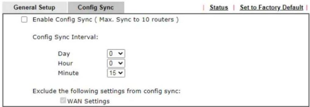
Note:
This feature requires that both routers are the same series, and the High Availability must be enabled for Config Sync to operate.

Available settings are explained as follows:
| Item | Description |
| Enable Config Sync (Max. Sync to 10 routers) | Select to enable configuration synchronization.All routers to be synchronized must have this checkbox selected.Note that config sync can be enabled byHot-Standbyredundancy method only. |
| Config Sync Interval Day / | Hour /Minute- The primary router will synchronize its configuration with secondary routers at every specified time interval. |
| Exclude the following settings from config sync | This setting is available when the Redundancy Method is set toHot Standby.Select the configuration settings to be excluded from synchronization. |
When you finish the configuration, please click OK to save and exit this page.
When the configuration method is set to "Hot Standby", the following settings will not be synchronized:
- WAN (user selectable)
• LAN -
LAN IPv6
-
router name
- admin and user passwords.
Example:
Take the following picture as an example. The upper Vigor3910 is regarded as primary device, the lower Vigor3910 is regarded as secondary device. When primary Vigor3910 Series is broken down, the secondary device could replace the primary role to take over all jobs as soon as possible. However, once the primary device is working again, the secondary device would be changed to original role to stand by.
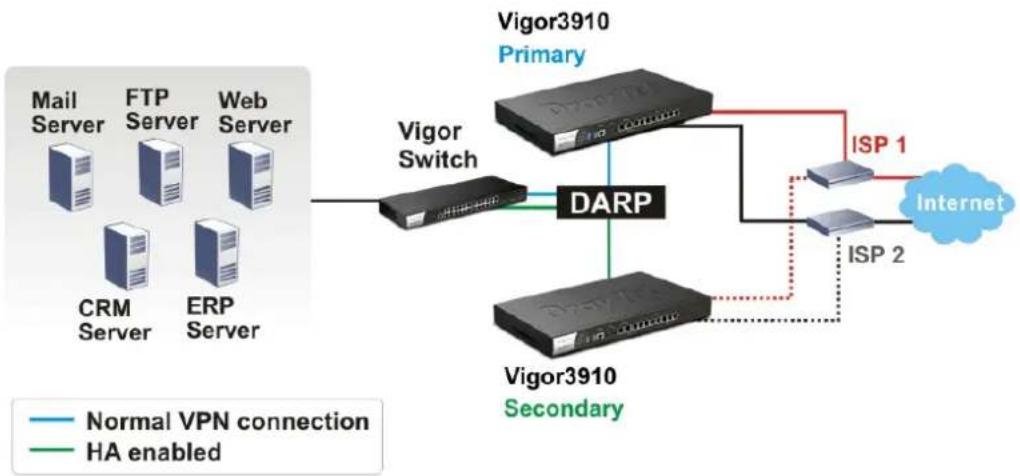
flowchart
graph TD
    A["Mail Server"] --> B["Vigor Switch"]
    C["FTP Server"] --> B
    D["Web Server"] --> B
    E["CRM Server"] --> B
    F["ERP Server"] --> B
    B --> G["DARP"]
    G --> H["Vigor3910 Primary"]
    G --> I["Vigor3910 Secondary"]
    H --> J["ISP 1"]
    I --> K["ISP 2"]
    J --> L["Internet"]
    K --> L
    style A fill:#f9f,stroke:#333
    style C fill:#f9f,stroke:#333
    style D fill:#f9f,stroke:#333
    style E fill:#f9f,stroke:#333
    style F fill:#f9f,stroke:#333
    style G fill:#ccf,stroke:#333
    style H fill:#ccf,stroke:#333
    style I fill:#ccf,stroke:#333
    style J fill:#dfd,stroke:#333
    style K fill:#dfd,stroke:#333
    style L fill:#dfd,stroke:#333
II-5-13 Local 802.1X General Setup
You may configure the built-in 802.1X server here. The local 802.X server can be used to authenticate wired and wireless LAN clients.
Applications >> Local 802.1X General Setup
Local 802.1X General Setup
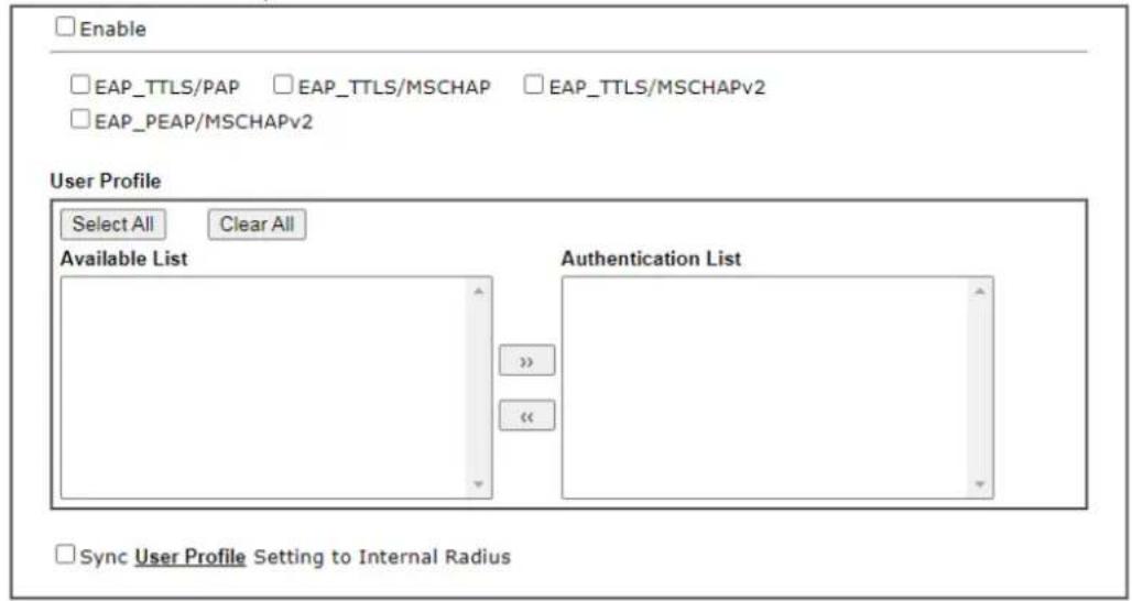
Note:
1. Only the user profiles which is enabled in User Management >> User Profile will be listed here.
2. Wired 802.1X used the same User Profile as its identity and password.

Available settings are explained as follows:
| Item | Description |
| Enable Select it to enable the built-in 802.1X server.At present, such feature can be used for wireless and wired 802.1x authentication. | |
| User Profile | Select All - Click to add all User Profiles to the 802.1X server.All profiles will appear under the Authentication List.Clear All - Remove all user profiles from the 802.1X server.All profiles will appear under Available List. |
| Sync User Profile .... | Make the enabling/ disabling setting for both Internal RADIUS and Local 802.1X synchronize for all of the user profiles (User Management>>User Profile).For example, if Local 802.1x is configured as Enabled (checked), the Internal RADIUS will be configured as Enabled too.3. Internal ServicesInternal RADIUSLocal 802.1XNote:Internal Services means the account and password of this user profile can be used by other application.OKRefreshClearCancelIf Local 802.1X is configured as Disabled (unchecked), theInternal RADIUS will be changed as Disabled too, even if it is enabled previously.3. Internal ServicesInternal RADIUS Local 802.1XNote:Internal Services means the account and password of this user profile can be used by other application.OK Refresh Clear Cancel |
| OK Click it to save the settings. | |
| Cancel Click it to give up all settings configuration. | |
When you finish the configuration, please click OK to save and exit this page.
II-5-14 Smart Action
Smart Action allows you to run some tasks (e.g., sending alerts, mails, or removing a VPN profile) automatically at a specified date, a cycle time, or a specified situation. Vigor user can pre-configure up to 64 profiles to manage different tasks.
Applications >> Smart Action
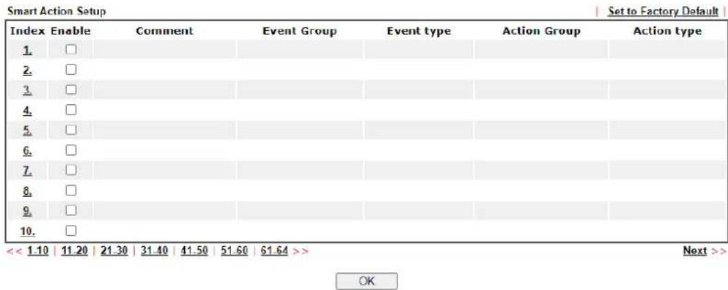
To configure a profile, click on its index to show the following settings page.
Applications >> Smart Action
Profile Index : 1
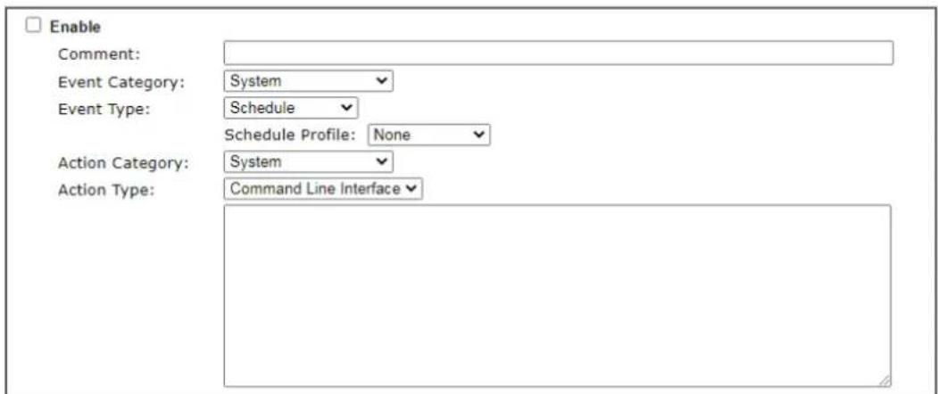
Note:
1. Comment can not contain characters \~ ! @ # \$ % ^ & " ( ) ' " { } | ;
2. If use CLI, user can put two or more commands on the same line separated by the semicolon
3. If use Webhook POST Content, only JSON format be accepted

Available settings are explained as follows:
| Item | Description |
| Enable Select to enable this function. | |
| Comment Describe the name/ focus of this profile. | |
| Event Category Select an event (e.g., System). | |
| Event Type Select an event type. | |
| Schedule - Specify an schedule profile to perform the job based on conditions determined by the action category and | |
| action type. Schedule Profile - Use the drop-down list to select a profile. If there is no schedule defined previously, click [Create New] to set a new schedule. Date and Time - Set the year, month, day, hour and minute to perform the job. CPU Usage - When the usage of the CPU reaches the threshold, a job based on the conditions set below will be performed. Usage threshold - Select a value. Memory Usage - When the usage of the memory reaches the threshold, a job based on the conditions set below will be performed. Usage threshold - Select a value. | |
| Action Category | Select an action category to set the corresponding action type. System Remote Dial-in User Lan-to-Lan |
| Action Type Available settings vary based on the selected action category. To perform a CLI or send out an e-mail, select System as the Action Category. Command Lint Interface - Put two or more commands on the same line separated by a semicolon. Mail Alert -Send an alert mail to a recipient. - Email Notification Object - Select an object. - Recipient - Enter the e-mail address of the recipient. - Subject - Enter the title of the e-mail. To enable, disable or terminate the VPN connection by the remote dial-in user, select Remote Dial-in User as the Action Category. Enable Profile - Enable the remote dial-in user profile. Disable Profile - Disable the selected remote dial-in user profile. Drop Connection - Terminate VPN connection for the selected remote dial-in user profile. To enable, disable or terminate the VPN connection by the LAN to LAN profile, select Lan-to-Lan as the Action Category, Enable Profile - Enable the LAN to LAN profile. Disable Profile - Disable the selected LAN to LAN profile. Drop Connection - Terminate VPN connection for the selected LAN to LAN profile. | |
When you finish the configuration, please click OK to save and exit this page.
Application Notes
A-1 How to Implement the LDAP/AD Authentication for User Management?
For simplifying the configuration of LDAP authentication for User Access Management, we implement "Group" feature.
There is no need to pre-configure user profile for each user on Vigor router anymore. We only need to configure the Groups DN, then the Vigor router (e.g., Vigor 2860 series) can pass the authentication to LDAP server with the pre-defined Group path.
Below shows the configuration steps:
-
Access into the web user interface of the Vigor router.
-
Open Applications>>Active Directory /LDAP to get the following page for configuring LDAP related settings.
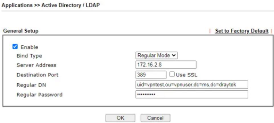
There are three types of bind type supported:
- Simple Mode – Just simply do the bind authentication without any search action.
- Anonymous – Perform a search action first with Anonymous account then do the bind authentication.
- Regular Mode- Mostly it is the same with anonymous mode. The different is that, the server will firstly check if you have the search authority.
For the regular mode, you'll need to type in the Regular DN and Regular Password.
- Create LDAP server profiles. Click the Active Directory /LDAP tab to open the profile web page and click any one of the index number link.
If we have two groups "RD1" and "SHRD" on LDAP server, we can configure two LDAP server profiles with different Group Distinguished Name.
Index No. 1
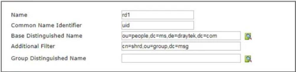
Note:
Please type in your additional filter for BaseDN search request. For example, "gidNumber=500" for OpenLDAP, and "msNPAIowDialin=TRUE" for AD.

and
Applications >> Active Directory /LDAP>>Server Profiles
Index No. 2
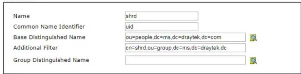
Note:
Please type in your additional filter for BaseDN search request. For example, "gidNumber=500" for OpenLDAP, and "msNPAIowDialin=TRUE" for AD.

-
Click OK to save the settings above.
-
Open User Management>>General Setup. Select User-Based as the Mode option.
User Management >> General Setup
General Setup
Mode Selection:
○ Rule-Based is a management method based on IP address. Administrator may set different firewall rules to different IP address.
User-Based is a management method based on user profiles. Administrator may set different firewall rules to different user profiles.
Notice for User-Based mode:
- In User-Based mode, Active Rules in Firewall will be applied to all LAN clients, packets that matches the Active Rules will be blocked or pass immediately, no user authentication is required.
- Only Inactive Rules in Firewall can be set for individual user profile. In User-Based mode, packets that do not match Active Rules will need authentication, and the Inactive Rule applied to the specific user profile will then take effect.
Authentication page:
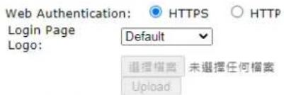
Login Page Greeting
☐ Display IP address on the dialog box pops up after successful login.
- Then open VPN and Remote Access>>PPP General Setup to check the profile(s) that will be authenticated with LDAP server.
VPN and Remote Access >> PPP General Setup
PPP General Setup
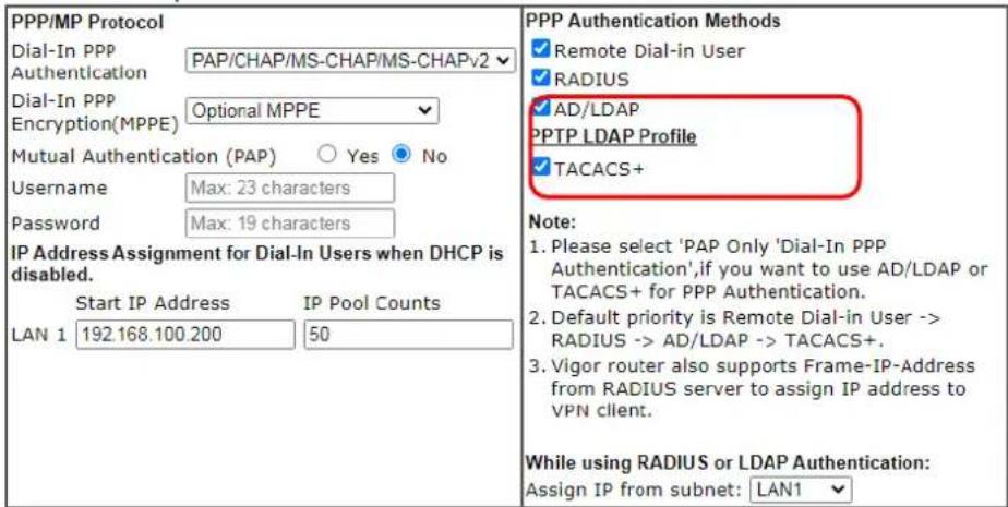
OK
After above configurations, users belong to either "rd1" or "shrd" group can access Internet after inputting their credentials on LDAP server.
A-2 How to use DrayDDNS?
Vigor router supports various DDNS service providers, user can set up user-defined profile to update the DDNS even the service provider is not on the list. Now, DrayTek starts to support our own DDNS service - DrayDDNS. We will provide a domain name for each Vigor router, this single domain name can record IP addresses of all WAN.
Set up DrayDDNS on DrayOS Router
- Go to Applications >> Dynamic DNS Setup. Enable Dynamic DNS Setup.
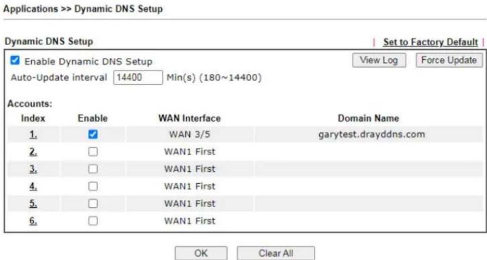
- Go to Wizards >> Service Activation Wizard page, wait for the router to connect to MyVigor server, then:
(a) Select DT-DDNS.
(b) Enter the desired Domain Name.
(c) Make sure you have read the License Agreement. Check I have read and accept the above Agreement, then click Next.
Service Activation Wizard
Select the service type that you want to activate
Activation Date : 2018-01-18
Web Content Filter(WCF) Service :
BPJM
License Agreement
This is a web content filter that is provided by the German government. It is a free service without any guarantee and will expire one year after activation. You may re-activate the service after expiry.
Cyren 30-Days Free Trial
License Agreement
This is a worldwide web content filter service. The free trail license can only be used once. At the end of the free trail period you may purchase the official one-year Cyren Web Content Filter from an authorized DrayTek reseller.
APP Enforcement(APPE) Service :
DT-APPE
License Agreement
Upgrade APPE Signature automatically.
Dynamic DNS(DDNS) Service :
DT-DDNS
License Agreement
This is a Dynamic Domain Name Service that is provided by DrayTek company. It is a free service will expire 1 year after activation. You may re-active the service after expiry.
Domain Name : domo .drayddns.com

have read and accept the above Agreement. (Please check this box).
Next>
Cancel
- Confirm the information, then click Activate.
Service Activation Wizard
Please confirm your settings
Sevice Type : Trial version
Sevice Activated : Dynamic DNS ( demo.drayddns.com )
Please click Back to re-select service type you to activate.
< Back
Activate
Cancel
- MyVigor server will reply with the service activation information.
DrayTek Service Activation
| Service Name | Start Date | Expire Date | Status |
| Web Content filter | --- | --- | Not Activated |
| APP Enforcement | --- | --- | Not Activated |
| DDNS | 2018-01-18 | 2019-01-18 | DT-DDNS |
Please check if the license fits with the service provider of your signature. To ensure normal operation for your router, update your signature again is recommended.
Copyright © DrayTek Corp. All Rights Reserved.
- Vigor router will contact with MyVigor server, then get the DrayDDNS license as well as the domain name back, and create the DDNS profile automatically. Please go to Applications >> Dynamic DNS Setup page to make sure the router has created the DDNS profile.
Applications >> Dynamic DNS Setup
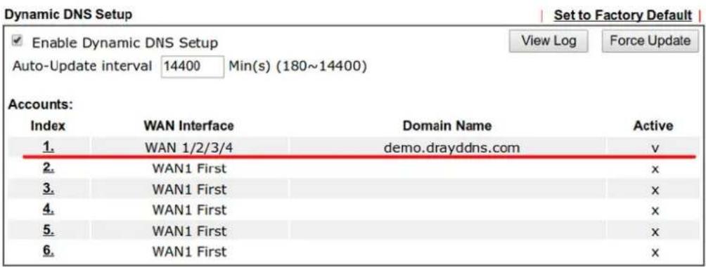

Note that, if your router does not get the domain after you activating the license, it may due to the router does not trigger the process, which to connect and get the license from MyVigor server. You may reboot the router to trigger the process.
Modify DrayDDNS Domain Name
Currently, only the domain name is allowed to be modified MyVigor website. We will need to register the router to MyVigor server, and log in to MyVigor website to modify it.
- Please visit https://myvigor.draytek.com/ or go to Applications >> Dynamic DNS Setup >> DrayDDNS profile and click Edit domain.
Index : 1
![Enable Dynamic DNS Account Service Provider DrayDDNS (Global) Status Activated [Start Date:2018-01-19 Expire Date:2019-01-19] Domain Name demo drayddns.com Edit domain Determine WAN IP WAN IP IPv4 IPv6 WAN Interfaces WAN 1 WAN 2 WAN 3 WAN 4 OK Clear Cancel](/content/2026/05/813922/images/860e6d10aa8fdac6632be9fa3d6c7d58c87a00945e972ac09d13b44b24bae46d.jpg)
- Log in to MyVigor Website, choose the profile, then click Edit DDNS settings.
My Information - My Products
Device Information
Device Name: FAE2000
Serial Number: 2016 0205
Model: Vigor2860 Series
Rename Transfer Back
Device's Service
Expired License
| Service | Provider | Action | Status | Start Date | Expired Date | Note |
| WCF | BPJM | Activate | On | - | - | - |
| WCF | Cyren | Trial | On | - | - | - |
| APPE | DT-APPE | Activate | On | - | - | - |
| DDNS | DT-DDNS | Renew | On | 2018-01-19 | 2019-01-19 | Edit DDNS settings |
- Input the desired Domain name and click Update.
Edit DDNS Settings
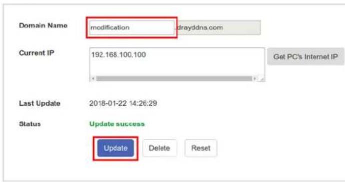
- Vigor router will get the modified domain name when the it performs next DDNS updating. We can click Sync domain to accelerate this process.
Index : 1
![Enable Dynamic DNS Account Service Provider DrayDDNS (Global) Status Activated [Start Date:2018-01-19 Expire Date:2019-01-19] Domain Name demo .drayddns.com Sync domain Determine WAN IP WAN IP IPv4 IPv6 WAN Interfaces WAN 1 WAN 2 WAN 3 WAN 4](/content/2026/05/813922/images/1811d0aeaec7b38b79404d6aa074a9662135aa3d37bc0e0d81318cc200c4e253.jpg)

- After few seconds, the router will get the new domain name and print it on the profiles list.
Applications >> Dynamic DNS Setup
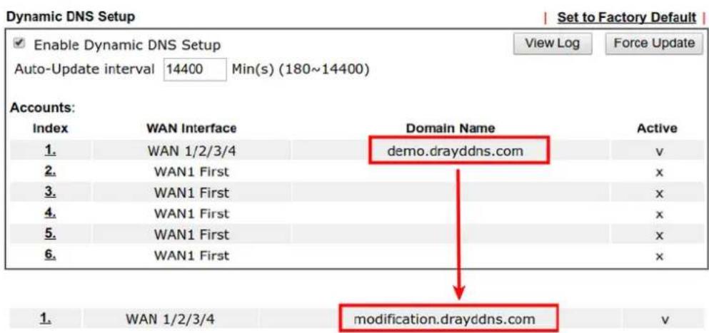
II-6 Routing
Route Policy (also well known as PBR, policy-based routing) is a feature where you may need to get a strategy for routing. The packets will be directed to the specified interface if they match one of the policies. You can setup route policies in various reasons such as load balance, security, routing decision, and etc.
Through protocol, IP address, port number and interface configuration, Route Policy can be used to configure any routing rules to fit actual request. In general, Route Policy can easily reach the following purposes:
Load Balance
You may manually create policies to balance the traffic across network interface.
Specify Interface
Through dedicated interface (WAN/ LAN/ VPN), the data can be sent from the source IP to the destination IP.
Address Mapping
Allows you specify the outgoing WAN IP address (es) for an internal private IP address or a range of internal private IP addresses.
Priority
The router will determine which policy will be adopted for transmitting the packet according to the priority of Static Route and Route Policy.
Failover to/Failback
Packets will be sent through another Interface or follow another Policy when the original interface goes down (Failover to). Once the original interface resumes service (Failback), the packets will be returned to it immediately.
Other routing
Specify routing policy to determine the direction of the data transmission.

Info
For more detailed information about using policy route, refer to SUPPORT >> TECH SUPPORT >>FAQs on www.draytek.com.
Web User Interface
Routing
Static Route
Load-Balance/Route Policy
Fast Routing
OSPF
BGP
II-6-1 Static Route
Go to Routing >> Static Route. You can create static routes so that traffic to specific IP addresses go through a particular LAN or WAN.
The Static Route Setup screen has separate tabs for IPv4 and IPv6. Select the appropriate tab to begin.
II-6-1-1 Static Route for IPv4
Routing >> Static Route
| IPv4 | IPv6 | Set to Factory Default | View Routing Table | ||
| Index | Enable | Destination Address | Mask | Gateway | Interface |
| 1. | |||||
| 2. | |||||
| 3. | |||||
| 4. | |||||
| 5. | |||||
| 6. | |||||
| 7. | |||||
| 8. | |||||
| 9. | |||||
| 10. | |||||
| 11. | |||||
| 12. | |||||
| 13. | |||||
Available settings are explained as follows:
| Item | Description |
| Set to Factory Default Clear | all of the settings and return to factory default settings. |
Viewing Routing Table Displays the routing table for your reference. Diagnostics >> View Routing Table 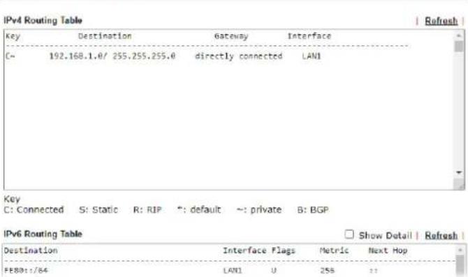 | |
| Index | The number (1 to 300) under Index allows you to open next page to set up static route. |
| Enable Enables or disables the static route. | |
| Destination Address Beginning destination address. | |
| Mask Subnet mask of the destination address. | |
| Gateway IP address of the gateway, which is the host that the traffic needs to go through to reach the destination. | |
| Interface The LAN or WAN that should be used to contact the gateway. | |
| Backup | Click it to backup the configuration of static route settings. |
| Restore Click it to restore the configuration of static route settings.Before clicking, make sure upload the configuration file onto Vigor router. | |
Add Static Routes to Private and Public Networks
Here is an example (based on IPv4) of setting Static Route in Main Router so that user A and B locating in different subnet can talk to each other via the router. Assuming the Internet access has been configured and the router works properly:
- use the Main Router to surf the Internet.
● create a private subnet 192.168.10.0 using an internal Router A (192.168.1.2)
● create a public subnet 211.100.88.0 via an internal Router B (192.168.1.3).
● have set Main Router 192.168.1.1 as the default gateway for the Router A 192.168.1.2.
Before setting Static Route, user A cannot talk to user B for Router A can only forward recognized packets to its default gateway Main Router.
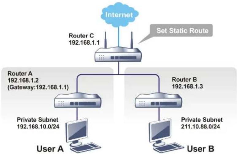
flowchart
graph TD
    A["Internet"] --> B["Router C 192.168.1.1"]
    B --> C["Router A 192.168.1.2 (Gateway:192.168.1.1)"]
    B --> D["Router B 192.168.1.3"]
    C --> E["User A"]
    C --> F["Private Subnet 192.168.10.0/24"]
    D --> G["User B"]
    D --> H["Private Subnet 211.10.88.0/24"]
    B --> I["Set Static Route"]
- Go to LAN page and click General Setup, select 1st Subnet as the RIP Protocol Control. Then click the OK button.

Info
There are two reasons that we have to apply RIP Protocol Control on 1st Subnet. The first is that the LAN interface can exchange RIP packets with the neighboring routers via the 1st subnet (192.168.1.0/24). The second is that those hosts on the internal private subnets (ex. 192.168.10.0/24) can access the Internet via the router, and continuously exchange of IP routing information with different subnets.
- Click the LAN >> Static Route and click on the Index Number 1. Check the Enable box. Please add a static route as shown below, which regulates all packets destined to 192.168.10.0 will be forwarded to 192.168.1.2. Click OK.
Routing >> Static Route Setup
Index No. 1
Enable
Destination IP Address
Subnet Mask
Gateway IP Address
Network Interface
192.168.10.0
255.255.255.255/32
192.168.1.2
LAN1
Note:
WAN7, WAN8, WAN9 are PVCs or VLANs that can be configured on the Multi-PVC/VLAN page.

Available settings are explained as follows:
| Item | Description |
| Enable Enables or disables the static route. | |
| Destination IP Address | Beginning destination address. Enter an IP address as the destination of the static route. |
| Subnet Mask Subnet mask of the destination address. Enter the subnet mask for the static route. | |
| Gateway IP Address Enter the IP address of the gateway, which is the host that the traffic needs to go through to reach the destination. | |
| Network Interface | Use the drop down list to specify an interface for such static route. The LAN or WAN that should be used to contact the gateway. |
- Return to Static Route Setup page. Click on another Index Number to add another static route as show below, which regulates all packets destined to 211.100.88.0 will be forwarded to 192.168.1.3. Click OK.
Routing >> Static Route Setup
Index No. 2

Note:
WAN7, WAN8, WAN9 are PVCs or VLANs that can be configured on the Multi-PVC/VLAN page.

- Go to Diagnostics and choose Routing Table to verify current routing table.
Diagnostics >> View Routing Table
| Key | Destination | Gateway | Interface |
| S~ | 192.168.10.0/ 255.255.255.255 | via 192.168.1.2 | LAN1 |
| C~ | 192.168.1.0/ 255.255.255.0 | directly connected | LAN1 |
| S~ | 211.100.88.0/ 255.255.255.255 | via 192.168.1.3 | LAN1 |
II-6-1-2 Static Route for IPv6
You can set up to 300 profiles for IPv6 static route. Click on a route index on the IPv6 tab to configure an IPv6 static route.
Routing >> Static Route Setup
| IPv4 | IPv6 | Set to Factory Default | View IPv6 Routing Table | |
| Index | Enable | Destination Address | Gateway | Interface |
| 1. | ||||
| 2. | ||||
| 3. | ||||
| 4. | ||||
| 5. | ||||
| 6. | ||||
| 7. | ||||
Available settings are explained as follows:
| Item | Description |
| Set to Factory Default Clear | all of the settings and return to factory default settings. |
| Viewing IPv6 Routing Table | Displays the routing table for your reference. |
| Index | The number (1 to 300) under Index allows you to open next page to set up static route. |
| Enable Enables or disables the static route. | |
| Destination Address Beginning destination address. | |
Click any underline of index number to get the following page.
Routing >> Static Route Setup
Index No. 1


Available settings are explained as follows:
| Item | Description |
| Enable Enables or disables the static route. | |
| Destination IPv6 Address / Prefix Len | Beginning destination address and the number of bits in the subnet mask of the destination IPv6 address.Enter the IP address with the prefix length for this entry. |
| Gateway IPv6 Address IP address of the gateway, which is the host that the traffic needs to go through to reach the destination. | |
| Network Interface The LAN | or WAN that should be used to contact the gateway. |
When you finish the configuration, please click OK to save and exit this page.
II-6-2 Load-Balance /Route Policy
The Load-Balance/ Route Policy feature gives you control over how different types of outbound traffic are routed, through any of the LANs, WANs or VPNs. The policy set in Load-Balance/ Route Policy always has higher priority than Default Route and Auto Load Balance set in WAN >> Internet Access, and always has lower priority than the Firewall Rules. Administrator may also define a priority to this policy.
II-6-2-1 General Setup
To add, delete or modify load balance or route policies, select Routing >> Load-Balance / Route Policy from the menu bar.
Routing >> Load-Balance/Route Policy

| Index | Enable | Comment | Protocol | Interface | Priority | Source | Destination | Dest Port | Move Up | Move Down |
| 1 | □ | Any | WAN1 | 200 | Any | Any | Any | Down | ||
| 2 | □ | Any | WAN1 | 200 | Any | Any | Any | UP | Down | |
| 3 | □ | Any | WAN1 | 200 | Any | Any | Any | UP | Down | |
| 4 | □ | Any | WAN1 | 200 | Any | Any | Any | UP | Down | |
| 5 | □ | Any | WAN1 | 200 | Any | Any | Any | UP | Down | |
| 6 | □ | Any | WAN1 | 200 | Any | Any | Any | UP | Down | |
| 7 | □ | Any | WAN1 | 200 | Any | Any | Any | UP | Down | |
| 8 | □ | Any | WAN1 | 200 | Any | Any | Any | UP | Down | |
| 9 | □ | Any | WAN1 | 200 | Any | Any | Any | UP | Down | |
| 10 | □ | Any | WAN1 | 200 | Any | Any | Any | UP | Down |
<< 1.10 | 11.20 | 21.30 | 31.40 | 41.50 | 51.60 | 61.70 | 71.80 | 81.90 | 91.100 | 101.110 | 111.120 | 121.130 | 131.140 | 141.150 | 151.160 | 161.
170 | 171.180 | 181.190 | 191.200 | 201.210 | 211.220 | 221.230 | 231.240 | 241.250 >> Next >>
○ Wizard Mode: most frequently used settings in three pages
Advance Mode: all settings in one page
Note:
The policies in blue are SD-WAN related, and can only be edited via ACS.
OK
Available settings are explained as follows:
| Item | Description |
| Rules per page The number | of rules to display on a single page. |
| Set to Factory Default Clear | the settings of all Load-Balance and Route Policy rules. |
| Index Rule index. Click to bring up the configuration page of the rule. | |
| Enable Select to enable this rule. | |
| Protocol Protocol(s) to which this rule applies. | |
| Interface LAN, IP Routed Subnet, WAN or VPN interface that the traffic described by this rule is to be directed. | |
| Priority The priority of this rule. | |
| Source The beginning and ending source IP addresses. | |
| Destination The beginning and ending destination IP addresses. | |
| Dest Port The beginning and ending destination port number. | |
| Move UP/Move Down Click to shift priority of rule up/ down by one. | |
| Wizard Mode | The setup wizard will present the most-commonly used rule settings in three steps. |
| Advance Mode All the rule settings will be shown on one configuration page. |
If Wizard Mode is selected, you will be guided through the configuration process in three steps. Only the most commonly used settings will be shown.
-
Click the Wizard Mode radio button.
-
Click Index 1. The setting page will appear as follows:
Routing >> Load-Balance/Route Policy
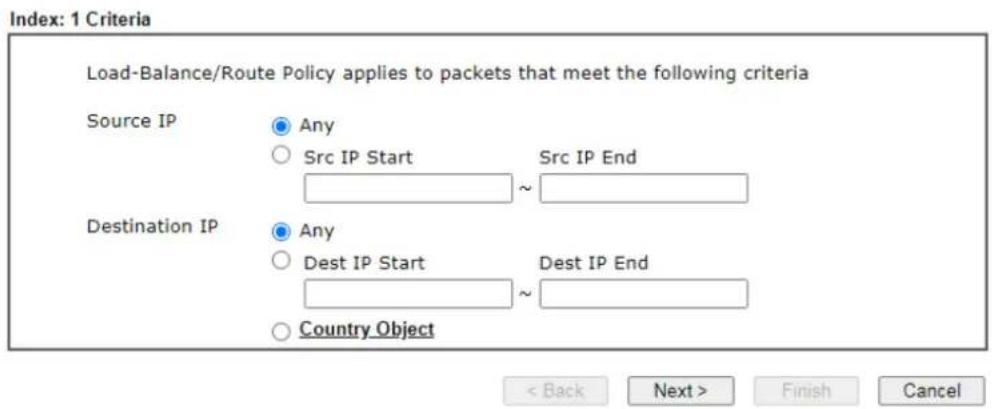
Available settings are explained as follows:
| Item | Description |
| Source IP | Source IP addresses to which this rule is to be applied.Any - This rule applies to all source IP addresses.Src IP Start, Src IP End - This rule applies to the specified range of source IP addresses. If there is only one source IP address, enter the address in both the Start and End fields. |
| Destination IP Destination IP addresses to which this rule is to be applied.Any - This rule applies to all destination IP addresses.Dest IP Start, Dest IP End - This rule applies to the specified range of destination IP addresses. If there is only one destination IP address, enter the address in both the Start and End fields.Country Object - Specify a country object. All the IPs coming from the country (countries) specified in the object will be passed through the WAN interface. | |
- Click Next to get the following page.
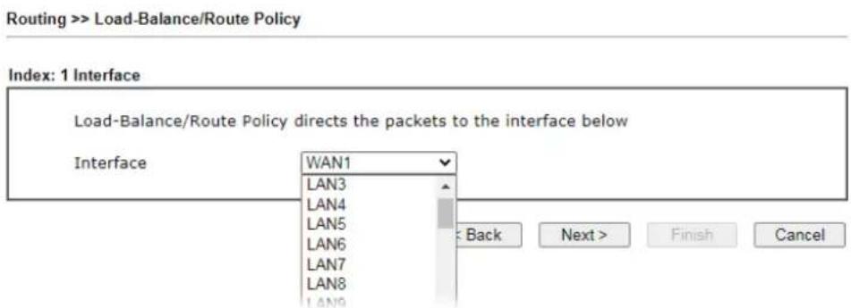
Available settings are explained as follows:
| Item | Description |
| Interface | You can select an interface from one of the following: WAN, LAN, VPN, and IP Routed Subnet. Packets match with the above criteria will be transferred to the interface chosen here. Select an interface from the list. |
- Specify an interface and click Next. The following page will appear only if you choose WAN1 \~WAN7 as Interface.
Routing >> Load-Balance/Route Policy
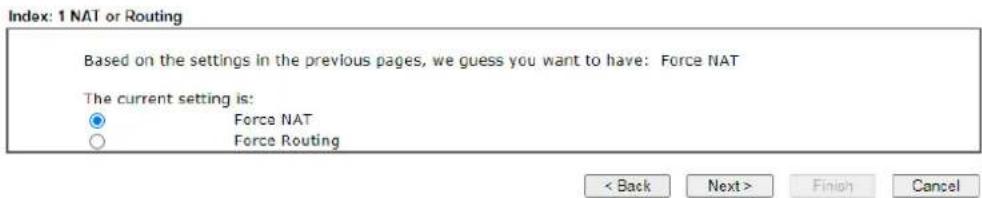
Available settings are explained as follows:
| Item | Description |
| Force NAT /Force Routing | It determines which mechanism that the router will use to forward the packet to WAN. |
- After choosing the mechanism, click Next to get the summary page for reference.
Load-Balance/Route Policy
Index: 1 Configuration Summary
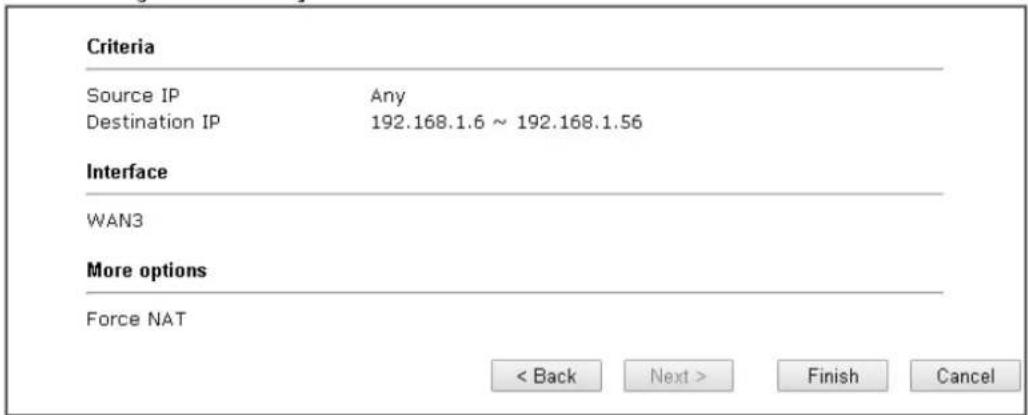
- If there is no error, click Finish to complete wizard setting. To make changes, click Back to return to the previous pages. To discard all changes, click Cancel.
If Advance Mode is selected, you will be presented with a single page with all the configurable settings for the rule.
- Click the Advance Mode radio button.
- Click Index 2 to access into the following page.
Index: 1
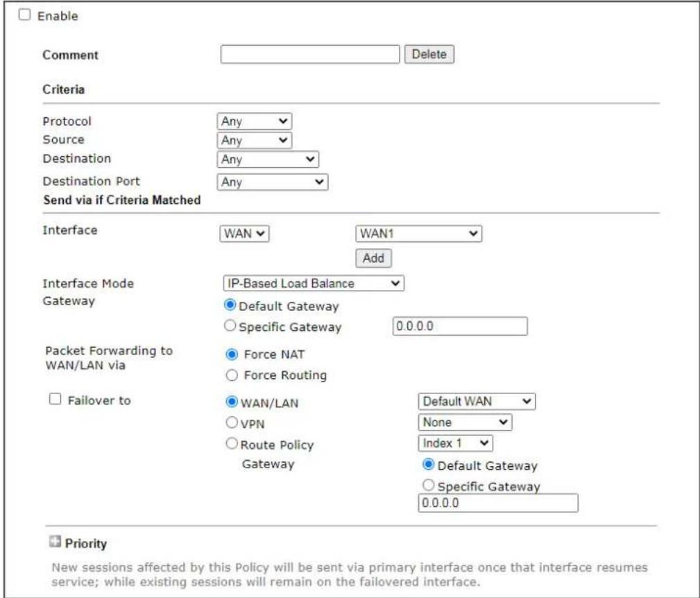

Available settings are explained as follows:
| Item | Description |
| Enable | Select to enable rule and unlock all fields for configuration. |
| Comment Type a brief | explanation for such profile. |
| Criteria | Router examines outgoing LAN traffic to find the first rule whose criteria are satisfied.Protocol - Use the drop-down menu to choose a proper protocol for the WAN interface.Source - Source IP addresses to which this rule is to be applied.Any - This rule applies to all source IP addresses.IP Range -This rule applies to the specified range of source IP addresses.- Start - Enter an address as the starting IP for such profile.- End - Enter an address as the ending IP for such profile.IP Subnet - This rule applies to source IP addresses defined by the specified network IP address and subnet mask.- Network - Enter an IP address here.- Mask - Use the drop down list to choose a suitable mask for the network.● IP Object / IP Group - Use the drop down list to choose a preconfigured IP object/ group.Destination - Destination IP addresses to which this rule is to be applied.● Any - This rule applies to all source IP addresses.● IP Range -This rule applies to the specified range of destination IP addresses.- Start - Enter an address as the starting IP for such profile.- End - Enter an address as the ending IP for such profile.● IP Subnet - This rule applies to destination IP addresses defined by the specified network IP address and subnet mask.- Network - Enter an IP address here.- Mask - Use the drop down list to choose a suitable mask for the network.● Domain Name - Specify a domain name as the destination.- Select - Click it to choose an existing domain name defined in Objects Setting>>String Object.- Delete - Remove current used domain name.- Add - Create a new domain name as the destination.● IP Object / IP Group - Use the drop down list to choose a preconfigured IP object/ group.● Country Object - Use the drop dwon list to choose a preconfigured object. Then all IPs within that country will be treated as the destination IP.Destination Port - Destination port numbers to which this rule is to be applied. As only TCP and UDP protocols use port numbers, this setting does not apply to the ICMP protocol.● Any - This rule applies to all destination ports.● Dest Port Range - This rule applies to the specified range of destination ports.- Start - Enter the destination port start for the destination IP.- End - Enter the destination port end for the destination IP. If this field is blank, it means that all the destination ports will be passed through the WAN interface. |
| Send via if Criteria Matched | If criteria are matched, the traffic will be sent to the designated interface and gateway.Interface - Packets match with the above criteria will be transferred to the interface chosen here. Select an interface from the list (WAN/ LAN: A WAN or LAN interface; VPN: A Virtual Private Network).Interface Mode - It is available if WAN is selected as the Interface.● IP Based Load Balance - The same source / destination IP pair will select the same WAN interface as policy. It is the default setting.● Session Based Load Balance - All of the WAN interfaces will be used (as out-going WAN) for passing through new sessions to get better transmission speed. Though good speed test result for throughput might be reached; however, some web site may not open smoothly, especially the site need authentication, e.g., FTP.If you have no strong demand about speed test result, keep default settings as IP based.Gateway- Select a gateway.● Default Gateway- Traffic will be sent to the default gateway address of the specified interface.● Specific Gateway- Traffic will be sent to the specified gateway address instead of the default gateway address.Packet Forwarding to WAN/LAN via- When you choose LAN/WAN (e.g., WAN1) as the Interface for packet transmission, you have to specify the way the packet forwarded to.● Force NAT- The source IP address will not be used to connect to the remote destination. Network Address Translation (NAT) will be used, where a common IP address will be used.● Force Routing- The source IP address will be preserved when connecting to the remote destination.Failover to- If the interface specified above loses connection, traffic can be forwarded to an alternate interface or be scrutinized by an alternate route policy.● WAN/LAN- Use the drop down list to choose an interface as an auto failover interface.● VPN- Use the drop down list to choose a VPN tunnel as a failover tunnel.● Route Policy- Use the drop down list to choose an existed route policy profile.● Gateway- The failed-over traffic can be sent to the Default Gateway of the alternate interface/ route policy, or a Specific Gateway at the specified IP address.Failback- When Failover tooption is enabled, Administrator could also enable Failbackto clear the existing session on Failover interface and return to the original interface immediately once the original interface resume its service. When Failback is not enabled, the router will only stop sending packets via the Failover interface when the existing sessions are cleared, and this might take a long time because some application will keep sending packet once a while. Therefore, Failback option is recommended if Administrator wants the traffic to go via the primary interface as soon as possible. |
| Priority Specifies the priority of the rule in relation to other rules.Lowering the priority value increases the priority of the rule, and vice versa. Routes in the routing table have a priority value of 150, whereas the default routes have a priority value of 250.The default priority value of Load Balance/ Route Policy rules is 200. To change the priority, move the slider or enter a | |
value.
- When you finish the configuration, please click OK to save and exit this page.
Routing >> Load-Balance/Route Policy

| Index | Enable | Comment | Protocol | Interface | Priority | Src IP Start | Src IP End | Dest IP Start | Dest IP End | Dest Port Start | Dest Port End | Move Up | Move Down |
| 1 | Any | WAN1 | 200 | Any | Any | Any | Any | Any | Any | Down | |||
| 2 | test | TCP/UDP | WAN1 | 200 | 172.16.0.0 | 172.16.255.255 | 192.168.1.61 | 192.168.1.66 | Any | Any | UP | Down | |
| 3 | Any | WAN1 | 200 | Any | Any | Any | Any | Any | Any | UP | Down | ||
| 4 | Any | WAN1 | 200 | Any | Any | Any | Any | Any | Any | UP | Down | ||
| 5 | Any | WAN1 | 200 | Any | Any | Any | Any | Any | Any | UP | Down | ||
| 6 | Any | WAN1 | 200 | Any | Any | Any | Any | Any | Any | UP | Down | ||
| 7 | Any | WAN1 | 200 | Any | Any | Any | Any | Any | Any | UP | Down | ||
| 8 | Any | WAN1 | 200 | Any | Any | Any | Any | Any | Any | UP | Down | ||
| 9 | Any | WAN1 | 200 | Any | Any | Any | Any | Any | Any | UP | Down | ||
| 10 | Any | WAN1 | 200 | Any | Any | Any | Any | Any | Any | UP | Down |
| << 1.10 | 11.20 | 21.30 | 31.40 | 41.50 | 51.60 | 61.70 | 71.80 | 81.90 | 91.100 | 101.110 | 111.120 | 121.130 | 131.140 | 141. |
| 150 | 151.160 | 161.170 | 171.180 | 181.190 | 191.200 | 201.210 | 211.220 | 221.230 | 231.240 | 241.250 | >> |

- Wizard Mode: most frequently used settings in three pages
- Advance Mode: all settings in one page
OK
II-6-2-2 Diagnose for Route Policy
The Diagnose function allows you to determine how a specific type of traffic from a host to a destination will be routed, and which routes, route policies and load balance rules match the criteria of the traffic.
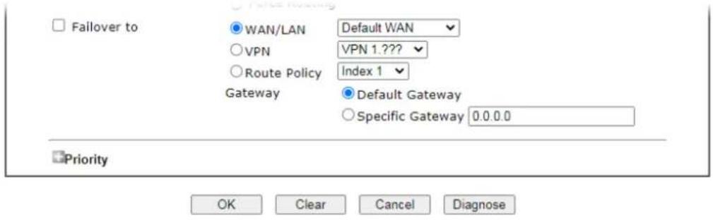
Click Diagnose.
Analyze a single packet
Select this mode to make Vigor router analyze how a single packet will be sent by a route policy.
Diagnostics >> Route Policy Diagnosis
Test how the packets will be routed

Analyze a single packet
○ Analyze multiple packets by uploading an input file
Packet Information
| Protocol | Any | ✓ |
| Src IP | Specify an IP | 192.168.1.1 |
| Dst IP | Specify an IP | 8.8.8.8 |
| Dst Port | Any Port | ✓ |
Analyze
Available settings are explained as follows:
| Item | Description |
| Packet Information Specify | the nature of the packets to be analyzed by Vigor router.Protocol - Specify a protocol for diagnosis.Src IP - IP address of host where the traffic originates.Specify an IP - One source IP address.Any IP- Source IP address is not specified.Subnet/IP Routed Subnet - Any source IP address on the specified subnet.Dst IP - IP address of the destination host.Specify an IP - One destination IP address.Any IP - Destination IP address is not specified.Dst Port - Number of port to which the traffic is sent. This setting is only applicable to UDP and TCP protocols. Use the drop down list to specify the destination port.Analyze - Click to analyze and display routes, route policies and load balance rules with matching criteria. If required, click export analysis to export the result as a file. |
The following shows an analysis example. The packet matched the criteria of one route policy.
Test how the packets will be routed
Mode ● Analyze a single packet ○ Analyze multiple packets by uploading an input file
Packet Information
| Protocol | Any | |
| Src IP | Specify an IP | 192.168.100.2 |
| Dst IP | Specify an IP | 172.16.2.191 |
| Dst Port | Any Port |
Analyze
Analysis

flowchart
graph LR
    A["the packet"] --> B["LAN"]
    B --> C["Vigor3910"]
    C --> D["The packet was sent via WAN5 according to the Static route '172.16.2.0/255.255.255.0 WAN5'"]
Matched Route
| Matched | Priority |
| 172.16.2.0/255.255.255.0 WANS | 150 |
Matched Policy
| Matched | Priority | failovered |
| Route Policy 2 | 200 | No |
Analyze multiple packets by uploading an input file
Diagnostics >> Route Policy Diagnosis

Test how the packets will be routed
Mode ○ Analyze a single packet ● Analyze multiple packets by uploading an input file
Input File
選擇檔案 未選擇任何檔案
( download an example input file)
Analyze
Available settings are explained as follows:
| Item | Description |
| Input File Browse - Click to | browse folder structure and select an input file.Download and example input file - Click to download a sample input file (blank “.csv” file). Then, click the Browse button to select that blank “.csv” file for saving the result of analysis. |
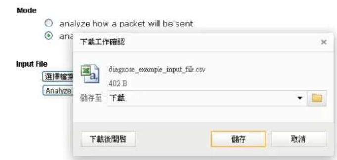
Analyze - After selecting input file, click to start the analysis process. Click the export button to export the result as a file.
Note that the analysis was based on the current "load-balance/route policy" settings, we do not guarantee it will be 100% the same as the real case.
The following shows the analysis of the sample input file. The matched routes and policies are highlighted in green. The Final Result column shows the outcome.
Diagnostics >> Route Policy Diagnosis

Test how the packets will be routed
Mode ○ Analyze a single packet ● Analyze multiple packets by uploading an input file
Input File
選擇欄點 表量選擇任何欄點
( download an example input file) Analyze
Analysis
export
| Input Packet Information | Matched Route | Matched Policy | Final Result | ||||||||
| Profile | Proto | Src IP | Dst IP | Dst Port | Route | Priority | Policy | Priority | failedered | Interface | Reason |
| LA-branch | ICMP | 192.168.1.10 | 10.10.10.10 | Any | No Match | N/A | No Match | N/A | No | (null) | The packet was dropped because neither "route" or "policy" was matched |
| NY-branch | TCP | 192.168.1.20 | 20.20.20.20 | 5060 | No Match | N/A | No Match | N/A | No | (null) | The packet was dropped because neither "route" or "policy" was matched |
| No Match | The packet was dropped because | ||||||||||
II-6-3 Fast Routing
This function allows for establishing a network connection with a built-in acceleration engine. Time can be saved and CPU usage can be reduced.
Available settings are explained as follows:
Routing >> Fast Routing / NAT
Fast Routing / NAT
□ Inter-LAN Fast Routing
□ LAN/WAN Fast NAT
Usage:
- Use hardware fast path to help establish connections with the same source and destination ip.
- Enable this function to reduce connection time and cpu usage.
Note:
Session limit and firewall port related settings may not work properly.
OK
| Item | Description |
| Inter-LAN Fast Routing | If enabled, the routing connection will be accelerated. |
| LAN/WAN Fast NAT If enabled, the NAT connection will be accelerated. | |
II-6-4 OSPF
OSPF(Open Shortest Path First), running within the AS, is a routing protocol based on IP protocol. It uses the algorithm of SPF (Shortest Path First) to calculate the route metric. It is suitable for large network and complicated data exchange. Vigor3910 supports up to OSPF version 2(only for IPv4).
The Autonomous System (AS) used in OSPF can be divided into several areas. Usually, Area 0 will be used as OSPF backbone which distributing the routing information among areas.
When you need faster convergence than distance vector, want to support much larger networks or want to have less susceptible to bad routing information, you can enable OSPF feature to fit your request. Note that both routers must support OSPF function at the same time to build the OSPF connection.
Open Routing >> OSPF to get the following page.
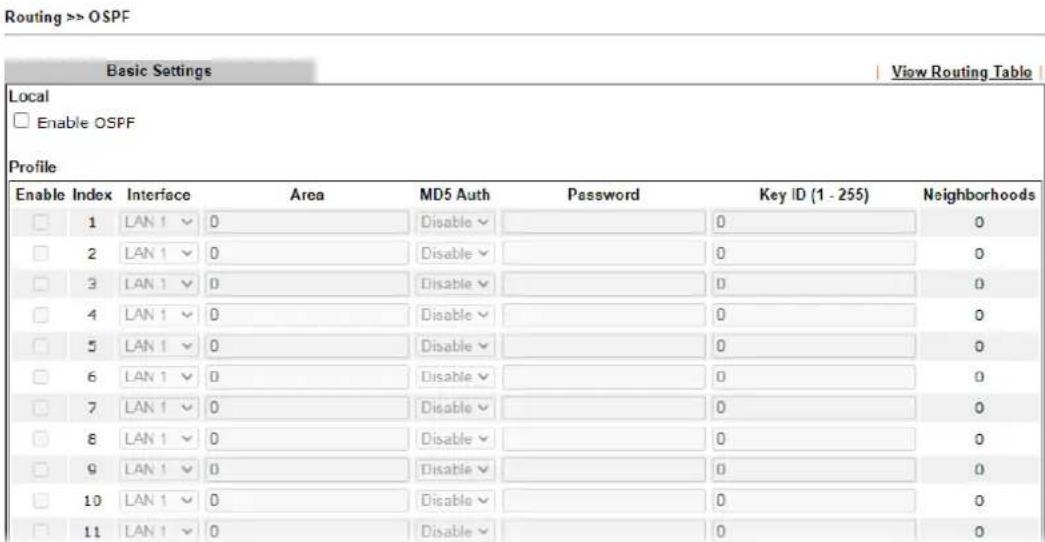
Available settings are explained as follows:
| Item | Description |
| Local | |
| Enable OSPF Check the box to enable the function. | |
| Profile | |
| Enable Check it to enable and configure an OSPF profile. | |
| Index 1 to 64 indicates profile 1 to profile 64. | |
| Interface | Choose a LAN / WAN interface to apply the settings configured for this profile. |
| Area An AS will be divided into several areas. Each area must be assigned with a dedicated number. | |
| MD5 Auth Enable/ disable the MD5 authentication mechanism for such profile. | |
| Password | Enter characters as the password for MD5 authentication. |
| Key ID (1-255) Specify the IP address of such Vigor router.Such ID will help Vigor router to be identified in an autonomous system. However, if no address is specified, | |
| then an IP address of the active interface will be used by system automatically. | |
| Neighborhoods | Displays current neighbors status in BGP routing environment. |
When you finish the configuration, please click OK to save and exit this page.
II-6-5 BGP
BGP means Border Gateway Protocol. It is a standardized exterior gateway protocol which can exchange routing and reachability information between autonomous systems (AS) on Internet.
The protocol TCP is used by two routers supporting BGP for data transmission. They can exchange the BGP routing information for each other. A BGP router is the “neighbor” of other BGP routers. Define the IP address, AS number for the router is essential for TCP connection of BGP routing information exchange.
AS, the abbreviation of Autonomous System, is a group interconnected with multiple IP addresses. Each AS shall be assigned with one AS number (ASN). The ASN is a unique identifier for AS to distinguish each network group in the whole interconnected network. It can be operated by one or several ISPs and follows the routing policies made by ISP.
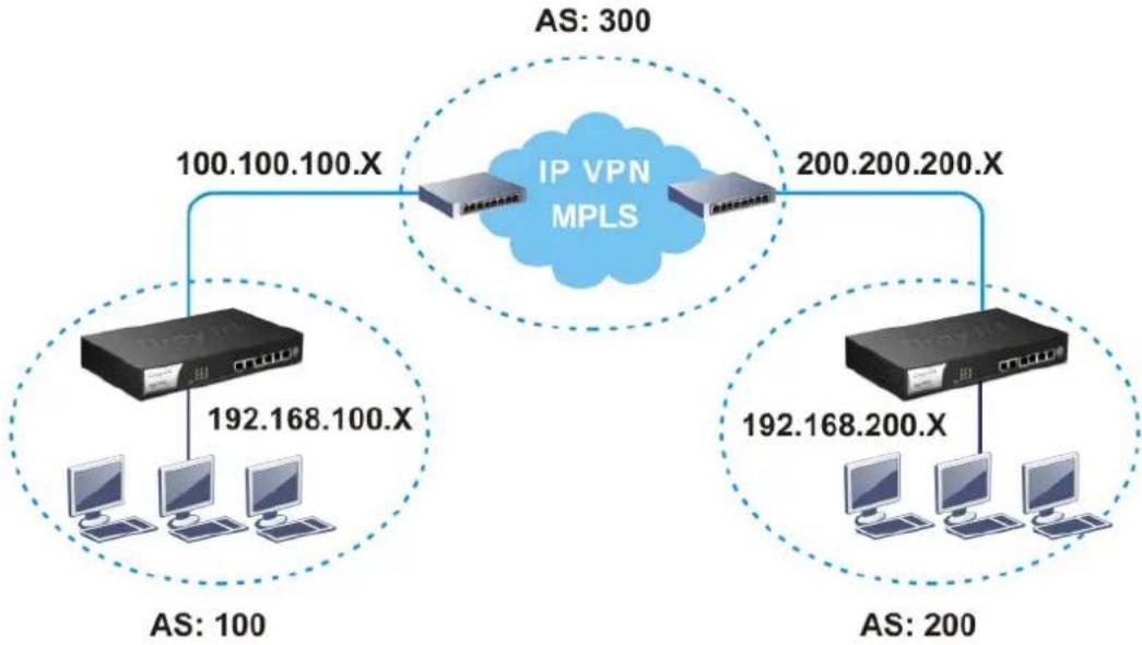
flowchart
graph TD
    A["IP VPN MPLS"] -->|100.100.100.X| B["Host 1"]
    A -->|200.200.200.X| C["Host 2"]
    B --> D["Computer 1"]
    B --> E["Computer 2"]
    B --> F["Computer 3"]
    C --> G["Computer 4"]
    C --> H["Computer 5"]
    style A fill:#f9f,stroke:#333
    style B fill:#ccf,stroke:#333
    style C fill:#ccf,stroke:#333
    style D fill:#dfd,stroke:#333
    style E fill:#dfd,stroke:#333
    style F fill:#dfd,stroke:#333
    style G fill:#dfd,stroke:#333
    style H fill:#dfd,stroke:#333
II-6-4-1 Basic Settings
Set general settings for for local router and neighboring routers.
Routing >> BGP
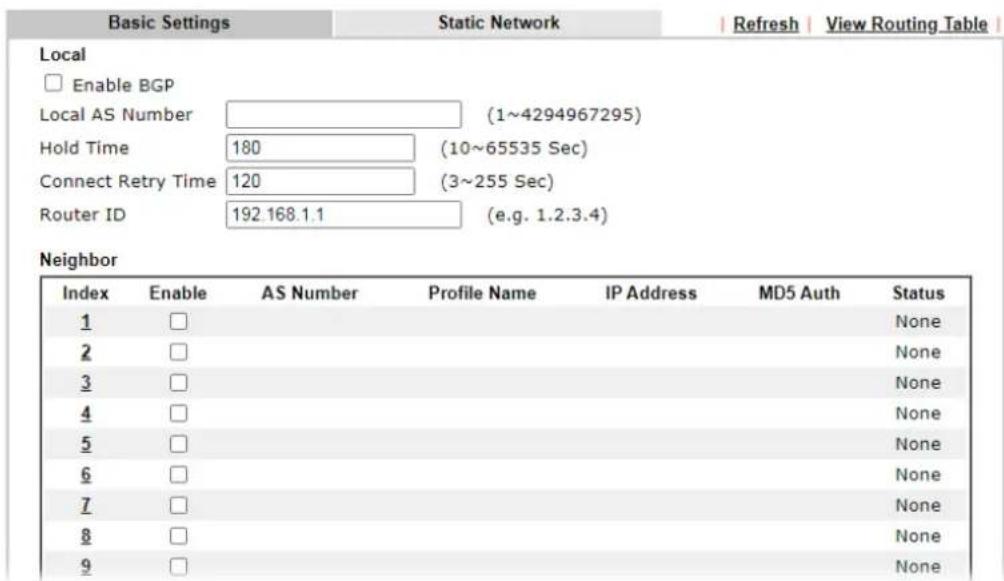
Available settings are explained as follows:
| Item | Description |
| Local | |
| Enable BGP Check the box to enable basic BGP function for local router. | |
| Local AS Number Set the AS number for local router. | |
| Hold Time Set the time interval (in seconds) to determine the peer is dead when the router is unable to receive any keepalive message from the peer within the time. | |
| Connect Retry Time | If the router fails to connect to neighboring router, it requires a period of time to reconnect.Set the time interval to do reconnection. |
| Router ID Specify the LAN subnet for the router. | |
| Neighbor | |
| Index Click the index number link to configure neighbor profile. | |
| Enable Check the box to enable the basic BGP function for neighboring router. | |
| AS Number Display the AS Number for neighboring router. | |
| Profile Name Display the name of the neighboring profile. | |
| IP Address Display the IP address specified for the neighboring profile. | |
| MD5 Auth Display the status (enable or disable) of MD5 Auth. | |
| Status | Display the connection status for local router and neighboring router. |
When you finish the configuration, please click OK to save and exit this page.
II-6-4-2 Static Network
This page allows you to configure up to eight neighboring routers for exchanging the routing information with the local router.
Routing >> BGP
| Basic Settings | Static Network | | View Routing Table | | |
| Select | Index | IP Address | Subnet Mask |
| □ | 1 | 255.255.255.254 / 31 ▼ | |
| □ | 2 | 255.255.255.254 / 31 ▼ | |
| □ | 3 | 255.255.255.254 / 31 ▼ | |
| □ | 4 | 255.255.255.254 / 31 ▼ | |
| □ | 5 | 255.255.255.254 / 31 ▼ | |
| □ | 6 | 255.255.255.254 / 31 ▼ | |
| □ | 7 | 255.255.255.254 / 31 ▼ | |
| □ | 8 | 255.255.255.254 / 31 ▼ | |
| □ | 9 | 255.255.255.254 / 31 ▼ | |
| □ | 10 | 255.255.255.254 / 31 ▼ | |
| □ | 11 | 255.255.255.254 / 31 ▼ | |
| □ | 12 | 255.255.255.254 / 31 ▼ | |
| □ | 13 | 255.255.255.254 / 31 ▼ | |
| □ | 14 | 255.255.255.254 / 31 ▼ | |
Available settings are explained as follows:
| Item | Description |
| Select Check the box to enable the configuration for the selected index entry. | |
| IP Address Enter the IP address for a router. | |
| Subnet Mask Choose the mask value for the IP address. | |
Application Notes
A-1 How to Customize a Secure Route between VPN Router and Remote Router by Using Route Policy
Example 1:
In the following figure, a LAN to LAN VPN tunnel is built between DrayTek VPN router (e.g., Vigor3910 Series) and the remote router. Firewall Router can receive all of the traffic coming from remote PC which wants to access into Internet; and send back the packets to Remote Router through VPN Router.
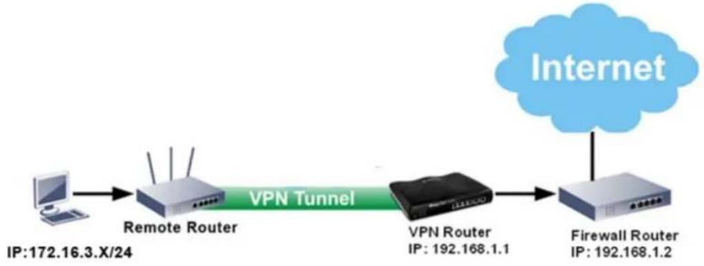
flowchart
graph LR
    A["Computer"] --> B["Remote Router"]
    B --> C["VPN Tunnel"]
    C --> D["VPN Router"]
    D --> E["Firewall Router"]
    F["Internet"] --> E
    style F fill:#f9f,stroke:#333
- Establish a VPN tunnel between VPN Router and the Remote Router.
- Change to default route for the router located in Remote Router.
- Access into the web user interface of the router in VPN Router. Then, open Routing >> Load-Balance / Route Policy and click Advance Mode.
Routing >> Load-Balance/Route Policy

| Index Enable Comment Protocol Interface Priority Src IP Start Src IP End Dest IP Start Dest IP End | |||||||||||||
| 1 | □ | Any | WAN5 | 200 | Any | Any | 192.168.18.18 | 192.168.18.18 | Any | Any | Down | ||
| 2 | □ | Any | WAN3 | 200 | Any | Any | Any | Any | Any | Any | UP | Down | |
| 3 | □ | Any | WAN1 | 200 | Any | Any | Any | Any | Any | Any | UP | Down | |
| 4 | □ | Any | WAN1 | 200 | Any | Any | Any | Any | Any | Any | UP | Down | |
| 5 | □ | Any | WAN1 | 200 | Any | Any | Any | Any | Any | Any | UP | Down | |
| 6 | □ | Any | WAN1 | 200 | Any | Any | Any | Any | Any | Any | UP | Down | |
| 7 | □ | Any | WAN1 | 200 | Any | Any | Any | Any | Any | Any | UP | Down | |
| 8 | □ | Any | WAN1 | 200 | Any | Any | Any | Any | Any | Any | UP | Down | |
| 9 | □ | Any | WAN1 | 200 | Any | Any | Any | Any | Any | Any | UP | Down | |
| 10 | □ | Any | WAN1 | 200 | Any | Any | Any | Any | Any | Any | UP | Down | |
| << 1-10 | 11-20 | 21-30 | 31-40 | 41-50 | 51-60 | 61-70 | 71-80 | 81-90 | 91-100 | 101-110 | 111-120 | 121-130 | 131- |
| 140 | 141-150 | 151-160 | 161-170 | 171-180 | 181-190 | 191-200 | 201-210 | 211-220 | 221-230 | 231-240 | 241- Next >> |
| 250 >> |
○ Wizard Mode: most frequently used settings in three pages
Advance Mode: all settings in one page
OK
- Click any Index number link (e.g., 1 in this case). Configure the settings as follows.
Routing >> Load-Balance/Route Policy
Index: 1
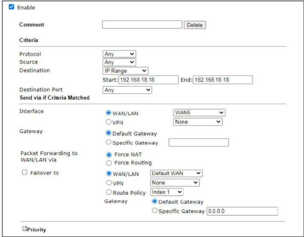

Now, if you want such route policy will be applied by Vigor router with higher priority, please adjust the value of Priority for such route policy. In general, default route is specified with the lowest priority for it value is fixed as "250". And Routes in Routing Table are fixed as "150". You can adjust the value for such route policy with lower value, e.g., 100 to ensure it will be applied to packets transmission with the highest priority.
- After finished the above settings, click OK to save the configuration.
Routing >> Load-Balance/Route Policy

| Index Enable Comment Protocol Interface Priority Src IP Start End | Src IP Start End | Src IP End | Dest IP Start | Dest IP End | Dest Port Start | Dest Port End | Move Up | Move Down | |||||
| 1 | ☐ | Any | WAN5 | 200 | Any | Any | 192.168.18.18 | 192.168.18.18 | Any | Any | Down | ||
| 2 | ☐ | Any | WAN3 | 200 | Any | Any | Any | Any | Any | Any | UP | Down | |
| 3 | ☐ | Any | WAN1 | 200 | Any | Any | Any | Any | Any | Any | UP | Down | |
| 4 | ☐ | Any | WAN1 | 200 | Any | Any | Any | Any | Any | Any | UP | Down | |
| 5 | ☐ | Any | WAN1 | 200 | Any | Any | Any | Any | Any | Any | UP | Down | |
| 6 | ☐ | Any | WAN1 | 200 | Any | Any | Any | Any | Any | Any | UP | Down | |
| 7 | ☐ | Any | WAN1 | 200 | Any | Any | Any | Any | Any | Any | UP | Down | |
| 8 | ☐ | Any | WAN1 | 200 | Any | Any | Any | Any | Any | Any | UP | Down | |
- To route the packets coming from the Firewall Router back to the remote router, access into the web user interface of the Firewall Router. Then, set "192.168.1.1/24" as the gateway IP address and set "172.16.3.0/24" as the destination IP address.
Example 2:
Below shows a scenario that local users behind Vigor router A want to access into a remote service (e.g., YouTube) which is blocked or restricted by local Service Provider in area with restrictions. A policy route can be created by the side of Router A to break through the Internet censorship circumvention.

flowchart
graph LR
    A["LAN1 /NAT"] -->|LAN1 GW: 168.95.98.254<br>WAN2 GW: 172.16.1.1<br>WAN3 GW: 27.244.84.241| B["Internet"]
    B --> C["Service provider in area with restrictions"]
    C --> D["Remote VPN Server LAN IP: 191.168.171.1/24"]
    D --> E["PC"]
    D --> F["IPTV Bind IP to MAC 192.168.1.10"]
A VPN tunnel has been established between Router A and router B.
- Access into the web user interface of Router A.
- Open Routing >> Load-Balance/Route Policy and click Advance Mode.
- Click any index number (e.g., #1 in this case).
- In the following web page, check Enable; type "192.168.1.10" as Src IP Range; type "213.57.89.100" as the Destination IP for the remote VPN server; and choose VPN as the Interface setting.
Routing >> Load-Balance/Route Policy
Index: 1
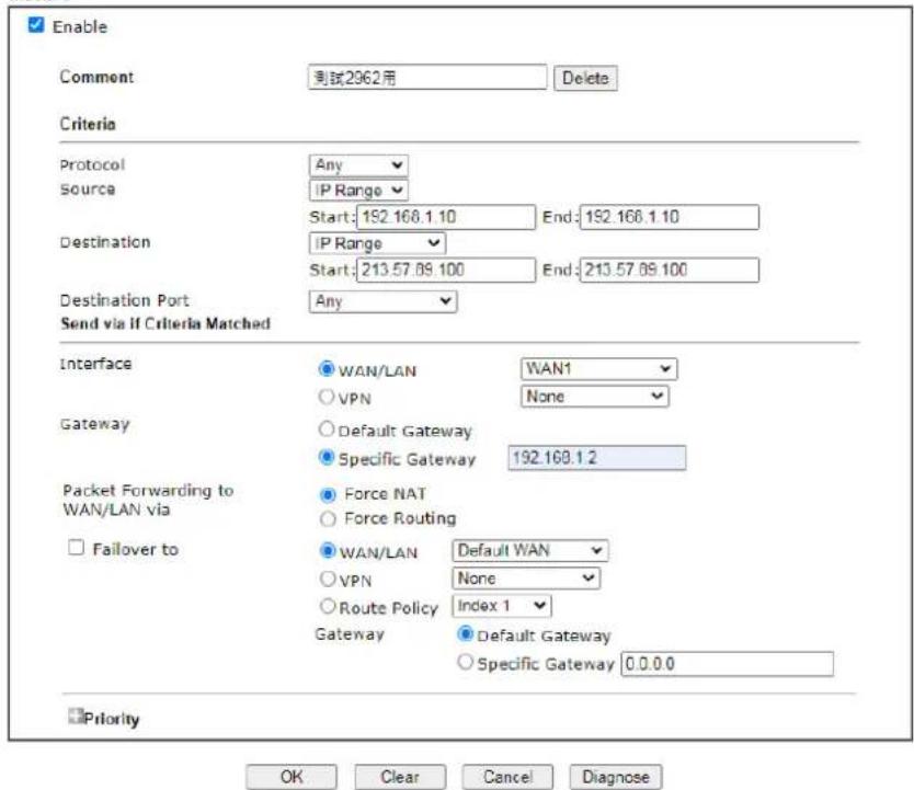
- Click OK to save the settings.
This page is left blank.
Part III VPN

VPN

SSL VPN

Certificate Management
A Virtual Private Network (VPN) is the extension of a private network that encompasses links across shared or public networks like the Internet. In short, by VPN technology, you can send data between two computers across a shared or public network in a manner that emulates the properties of a point-to-point private link.
It is a form of VPN that can be used with a standard Web browser.
A digital certificate works as an electronic ID, which is issued by a certification authority (CA). It contains information such as your name, a serial number, expiration dates etc., and the digital signature of the certificate-issuing authority so that a recipient can verify that the certificate is real. Here Vigor router support digital certificates conforming to standard X.509.
III-1 VPN and Remote Access
A Virtual Private Network (VPN) is the extension of a private network that encompasses links across shared or public networks like the Internet. In short, by VPN technology, you can send data between two computers across a shared or public network in a manner that emulates the properties of a point-to-point private link.
The VPN built is suitable for:
● Communication between home office and customer
- Secure connection between Teleworker, staff on business trip and main office
● Exchange data between remote office and main office
● POS between chain store and headquarters
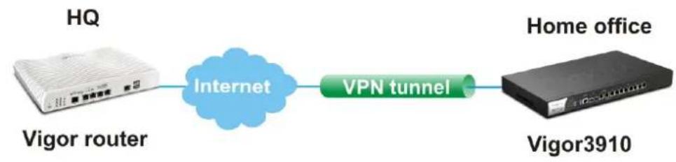
flowchart
graph LR
    A["HQ"] -->|Internet| B["Vigor router"]
    B --> C["VPN tunnel"]
    C --> D["Home office"]
    D --> E["Vigor3910"]

flowchart
graph LR
    A["HQ"] --> B["Internet"]
    C["Vigor router"] --> B
    B --> D["VPN tunnel"]
    B --> E["VPN tunnel"]
    D --> F["Tele-worker 1"]
    E --> G["Tele-worker 2"]
Web User Interface
(3) 10.14.15.16
VPN and Remote Access
Remote Access Control
PPP General Setup
SSL General Setup
IPsec General Setup
IPsec Peer Identity
VPN Matcher Setup
OpenVPN
WireGuard
Remote Dial-in User
LAN to LAN
VPN TRUNK Management
Connection Management
III-1-1 Remote Access Control
Enable the necessary VPN service as you need. If you intend to run a VPN server inside your LAN, you should disable the VPN service of Vigor Router to allow VPN tunnel pass through, as well as the appropriate NAT settings, such as DMZ or open port.
III-1-1-1 Remote Access Control Setup
VPN and Remote Access >> Remote Access Control
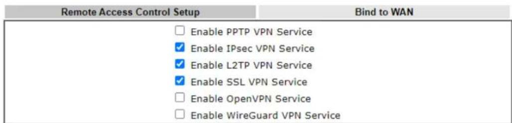
Note:
To allow VPN pass-through to a separate VPN server on the LAN, disable any services above that use the same protocol and ensure that NAT Open Ports or Port Redirection is also configured.

| Item | Description |
| Enable PPTP VPN Service | This is the one of the earliest VPN protocols and is natively supported by all Microsoft Windows versions since Windows 95, all Android devices, iOS devices before version 10, and Mac OS X before version 10.12. It is easy to set up, has low overhead, and moderately secure. |
| Enable IPSec VPN Service | This is a network protocol that encrypts traffic between two network locations. Windows, by means of Windows Firewall, natively supports IPsec tunnels between endpoints with static IP addresses. For computers with dynamically-assigned IP addresses, DrayTek provides the SmartVPN client . |
| Enable L2TP VPN Service | This is a tunneling protocol used in VPNs. It does not encrypt network traffic unless used in conjunction with IPsec. |
| Enable SSL VPN Service | This type of VPN uses Secure Sockets Layer (SSL) and Transport Layer Security (TLS), which are also used to encrypt traffic to and from websites. Since SSL and TLS work on top of TCP and UDP, which are the most common internet protocols, they are less likely to be have issues with firewalls and gateways. |
| Enable OpenVPN Service | OpenVPN is an open-source VPN technique and could authenticate each other using pre-shared secret keys, certificates, or username/ password. |
| Enable WireGuard VPN Service | WireGuard is a secure, fast, and modern open-source VPN Protocol. This type of VPN connection is made by exchanging public keys and intends to be considerably more performant than OpenVPN. |
To save changes on the page, select OK; to discard changes, select Cancel; to clear settings on this page and revert to default settings, select Clear.
III-1-2 Bind to WAN
Select the WAN interfaces to accept PPTP VPN, IPsec VPN, L2TP VPN, inbound SSL VPN, OpenVPN and WireGuard connections.
VPN and Remote Access >> Remote Access Control
| Remote Access Control Setup | Bind to WAN | ||||||
| PPTP VPN Service | WAN1 | WAN3 | WAN5 | WAN6 | WAN7 | WAN8 | |
| IPsec VPN Service | WAN1 | WAN3 | WAN5 | WAN6 | WAN7 | WAN8 | |
| L2TP VPN Service | WAN1 | WAN3 | WAN5 | WAN6 | WAN7 | WAN8 | |
| SSL VPN Service | WAN1 | WAN3 | WAN5 | WAN6 | WAN7 | WAN8 | |
| OpenVPN Service | WAN1 | WAN3 | WAN5 | WAN6 | WAN7 | WAN8 | |
| WireGuard Service | WAN1 | WAN3 | WAN5 | WAN6 | WAN7 | WAN8 | |
| OK | Clear | Cancel |
III-1-2 PPP General Setup
This page allows configuration of Point-to-Point Protocol (PPP) used by PPTP and L2TP VPN connections. From the Main Menu select VPN and Remote Access >> PPP General Setup to bring up the following configuration page.
VPN and Remote Access >> PPP General Setup
PPP Gonoral Setup
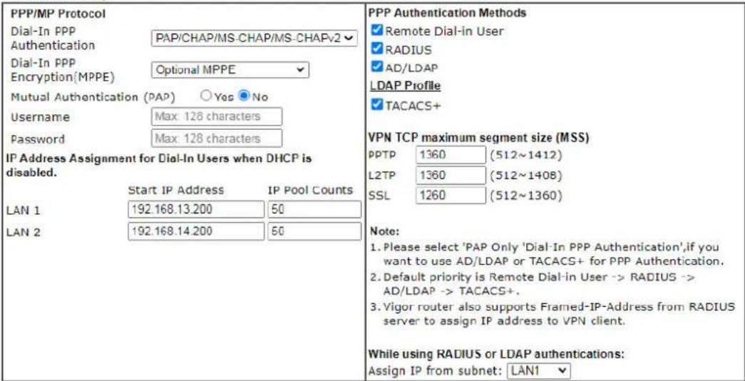
OK
Available settings are explained as follows:
| Item | Description |
| Dial-In PPP Authentication | PAP Only - Authenticate dial-in users using the PAP protocol only.PAP/CHAP/MS-CHAP/MS-CHAPv2 - Attempt to authenticate dial-in users using various CHAP protocols, and if the remote VPN client fails to authenticate, fall back to PAP. |
| Dial-In PPP Encryption (MPPE) | Specifies if PPP encryption (MPPE) is to be used for dial-in VPN connections.Optional MPPE - MPPE is optional. If the VPN client supports MPPE, PPP data will be encrypted.Require MPPE (40/128bits) - Require PPP encryption for dial-in VPN connections. Both 40- and 128-bit encryption schemes are allowed. The remote dial-in user will use 40-bit to perform encryption prior to using 128-bit for encryption. In other words, if 128-bit MPPE encryption method is not available, then 40-bit encryption scheme will be applied to encrypt the data.Maximum MPPE - Require 128-bit PPP encryption for all dial-in VPN connections. |
| Mutual Authentication (PAP) | Specifies if mutual authentication is to be used. Some VPN peers (e.g., certain Cisco routers) require bi-directional authentication used for providing stronger security.When mutual authentication is enabled,Username and Password fields should also be populated using values fromthe VPN peer. The maximum lengths of these fields are 23 and 19 characters, respectively.Yes - Enable mutual authentication.No - Disable mutual authentication. |
| IP Address Assignment for Dial-In Users | LAN1 - When the router's DHCP server is disabled, the router will assign IP addresses to dial-in VPN users starting with the IP address specified in Start IP Address. The total number of dial-in VPN IP addresses to be given out is specified in IP Pool Counts.LAN# will be available if it is enabled. Refer to LAN>>General Setup for enabling the LAN interface. |
| PPP Authentication Methods | The credentials to be used for PPP authentication will be obtained from the selected sources, in the following order:Remote Dial-in User - The usernames and passwords in VPN and Remote Access >> Remote Dial-in User section will be used.RADIUS - An external RADIUS server is to be used for authentication. Please be sure to set up the RADIUS server in Applications >> RADIUS/ TACACS+ section.AD/LDAP - An Active Directory/ LDAP server is to be used for authentication. Please be sure to configure AD and LDAP settings in Applications >> Active Directory/ LDAP.TACACS+ - A TACACS+ server is to be used for authentication. Please be sure to set up the RADIUS server in Applications >> RADIUS/ TACACS+ section. |
| PPTP LDAP Profile | Configured LDAP profiles will be listed under such item.Simply check the one you want to enable the PPP authentication by LDAP server profiles.However, if there is no profile listed, simply click the link of PPTP LDAP Profile to create/ add some new LDAP profiles you want. |
| VPN TCP maximum segment size (MSS) | Set the maximum segment size (MSS) for different VPN types.Please specify the MSS values for each type to avoid packets cut by MTU during the data transmission period via the IPsec VPN connection. |
| While using Radius or LDAP Authentication | When the dial-in VPN user is authenticated using credentials from the Remote Dial-in User section, an IP address from the LAN specified in the user profile will be assigned. When the user is authenticated using credentials from other sources (RADIUS, AD, TACACS+), the assigned IP address will be drawn from the address pool of the LAN specified here. |
After finishing all the settings here, please click OK to save the configuration.
III-1-3 SSL General Setup
SSL VPN (Secure Sockets Layer virtual private network) is a form of VPN that encrypts traffic using SSL, which is the same technology used on secured websites. Because of SSL's prominence as an encryption protocol on the Internet, most networks have few restrictions on SSL traffic, and as a result SSL VPN is more likely to work when other VPN technologies experience difficulties due to obstacles such as firewalls and Network Address Translation (NAT).
In short,
- It is not necessary for users to preinstall VPN client software for executing SSL VPN connection.
- There are less restrictions for the data encrypted through SSL VPN in comparing with traditional VPN.
This page determines the general configuration for SSL VPN Server and SSL Tunnel.
VPN and Remote Access >> SSL General Setup
SSL General Setup


Available settings are explained as follows:
| Item | Description |
| Bind to WAN Select the WAN | AN interfaces to accept inbound SSL VPN connections. |
| Port | The port to be used for SSL VPN server. This is separate from the management port (HTTPS Port) which is configured in System Maintenance>>Management. The default setting is 443. |
| Server Certificate Specify | the certificate to be used for SSL connections. Select a certificate from imported or generated certificates on the router, or choose Self-signed to use the router's built-in default certificate. The selected certificate can be used in SSL VPN server and HTTPS Web Proxy. |
To save changes on this page, select OK; to discard changes, select Cancel.
III-1-4 IPsec General Setup
In IPsec General Setup, there are two major parts of configuration.
There are two phases of IPsec.
- Phase 1: negotiation of IKE parameters including encryption, hash, Diffie-Hellman parameter values, and lifetime to protect the following IKE exchange, authentication of both peers using either a Pre-Shared Key or Digital Signature (x.509). The peer that starts the negotiation proposes all its policies to the remote peer and then remote peer tries to find a highest-priority match with its policies. Eventually to set up a secure tunnel for IKE Phase 2.
- Phase 2: negotiation IPsec security methods including Authentication Header (AH) or Encapsulating Security Payload (ESP) for the following IKE exchange and mutual examination of the secure tunnel establishment.
There are two encapsulation methods used in IPsec, Transport and Tunnel. The Transport mode will add the AH/ ESP payload and use original IP header to encapsulate the data payload only. It can just apply to local packet, e.g., L2TP over IPsec. The Tunnel mode will not only add the AH/ ESP payload but also use a new IP header (Tunneled IP header) to encapsulate the whole original IP packet.
Authentication Header (AH) provides data authentication and integrity for IP packets passed between VPN peers. This is achieved by a keyed one-way hash function to the packet to create a message digest. This digest will be put in the AH and transmitted along with packets. On the receiving side, the peer will perform the same one-way hash on the packet and compare the value with the one in the AH it receives.
Encapsulating Security Payload (ESP) is a security protocol that provides data confidentiality and protection with optional authentication and replay detection service.
VPN IKE/IPsec General Setup
(Dial-in settings for Remote Dial-In users and LAN-to-LAN VPN Client with Dynamic IP.)
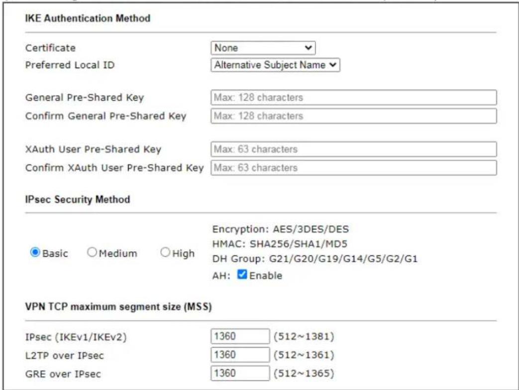

Available settings are explained as follows:
| Item | Description |
| IKE Authentication Method | This usually applies to those are remote dial-in user or node (LAN-to-LAN) which uses dynamic IP address and IPsec-related VPN connections such as L2TP over IPsec and IPsec tunnel. There are two methods offered by Vigor router for you to authenticate the incoming data coming from remote dial-in user, Certificate (X.509) and Pre-Shared Key.Certificate - X.509 certificates can be used for IKE authentication. To set up certificates on the router, go to the Certificate Management section.Preferred Local ID - Specify the preferred local ID information (Alternative Subject Name First or Subject Name First) for IPsec authentication while the client is using the general setting (without a specific Peer IP or ID in the VPN profile).General Pre-Shared Key- Define the PSK key for general authentication.Confirm General Pre-Shared Key- Re-enter the characters to confirm the pre-shared key.XAuth User Pre-Shared Key - Define the PSK key for IPsec XAuth authentication.Confirm XAuth User Pre-Shared Key- Re-enter thecharacters to confirm the pre-shared key for IPsec XAuth authentication.Note: Any packets from the remote dial-in user which does not match the rule defined inVPN and Remote Access>>Remote Dial-In Userwill be applied with the method specified here. |
| IPsec Security Method | Available methods includeBasic, Mediumand High. Each method offers different encryption, HMAC and DH Group.Basic- Authentication Header (AH) means data will be authenticated, but not be encrypted. By default, this option is active.Medium- When this option is selected, the Authentication Header (AH) protocol can be used to provide authentication to IPsec traffic.High- When this option is selected, the Encapsulating Security Payload (ESP) protocol can be used to provide authentication and encryption to IPsec traffic. Three encryption standards are supported for ESP: DES, 3DES and AES, in ascending order of security. |
| VPN TCP maximum segment size (MSS) | Set the maximum segment size (MSS) for different VPN types. Please specify the MSS values for each type to avoid packets cut by MTU during the data transmission period via the IPsec VPN connection. |
After finishing all the settings here, please click OK to save the configuration.
III-1-5 IPsec Peer Identity
This screen allows creating profiles of subject alternative names (SANs) and distinguished names/ subject names that can be used for IPsec peer authentication in LAN-to-LAN or remote user dial-in VPN connections.
VPN and Remote Access >> IPsec Peer Identity
| Index | Enable | Name | Index | Enable | Name |
| 1. | √ | bb | 17. | □ | ??? |
| 2. | □ | ??? | 18. | □ | ??? |
| 3. | □ | ??? | 19. | □ | ??? |
| 4. | □ | ??? | 20. | □ | ??? |
| 5. | □ | ??? | 21. | □ | ??? |
| 6. | □ | ??? | 22. | □ | ??? |
| 7. | □ | ??? | 23. | □ | ??? |
| 8. | □ | ??? | 24. | □ | ??? |
| 9. | □ | ??? | 25. | □ | ??? |
| 10. | □ | ??? | 26. | □ | ??? |
| 11. | □ | ??? | 27. | □ | ??? |
| 12. | □ | ??? | 28. | □ | ??? |
| 13. | □ | ??? | 29. | □ | ??? |
| 14. | □ | ??? | 30. | □ | ??? |
| 15. | □ | ??? | 31. | □ | ??? |
| 16. | □ | ??? | 32. | □ | ??? |
Available settings are explained as follows:
| Item | Description |
| Set to Factory Default Click it to clear all indexes. | |
| Index Click the index number of the profile the view or edit its settings. | |
| Enable Check to enable the profile. | |
| Name User-entered name that identifies the profile. | |
The following setup screen is shown after a profile index has been clicked.
VPN and Remote Access >> IPsec Peer Identity
Profile Index : 1
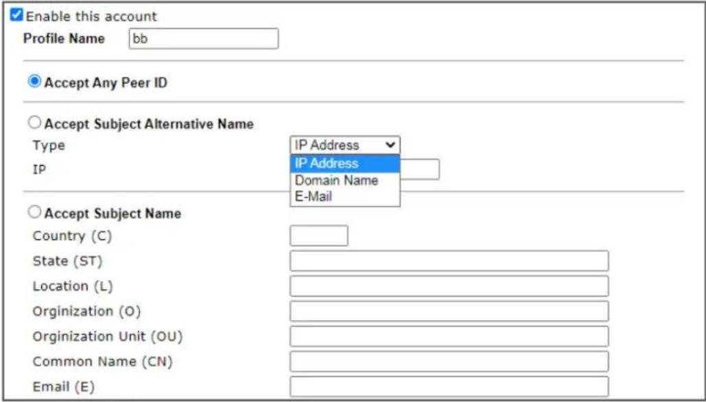

Available settings are explained as follows:
| Item | Description |
| Enable this account Check to enable such account profile. | |
| Profile Name A name that allows you to identify this profile. The maximum length of the name you can set is 32 characters. | |
| Accept Any Peer ID When this option is selected, the router accepts any subject alternative name or subject name as valid, regardless of the type and value. | |
| Accept Subject Alternative Name | When this option is selected, the router accepts the type and value of the specified subject alternative name as valid authentication. Supported subject alternative types are IP Address, Domain Name and E-Mail. |
| Accept Subject Name When this option is selected, the router performs peer authentication by matching the values of the different subject name fields. These fields include Country (C), State (ST), Location (L), Organization (O), Organization Unit (OU), Common Name (CN), and Email (E). | |
To save changes on the page, select OK; to discard changes, select Cancel; to clear settings on this page and revert to default settings, select Clear.
III-1-6 VPN Matcher Setup
Normally, to establish VPN connection, at least one peer must have a public IP address. The VPN Matcher server can help two Draytek routers behind NAT establish a secure VPN tunnel for data transmission between each other. Refer to the following figure.
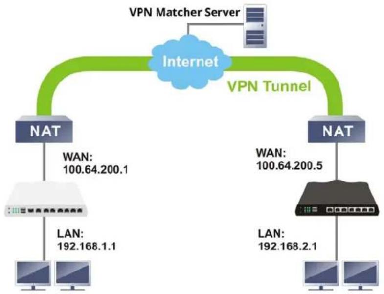
flowchart
graph TD
    A["Internet"] --> B["NAT"]
    A --> C["NAT"]
    B --> D["LAN: 192.168.1.1"]
    C --> E["LAN: 192.168.2.1"]
    F["VPN Matcher Server"] --> A
    G["VPN Tunnel"] --> A
    H["WAN: 100.64.200.1"] --> B
    I["WAN: 100.64.200.5"] --> C
There is one limitation for the VPN connection. Both routers must be behind a cone NAT, but not symmetric NAT.
Go to VPN and Remote Access>>VPN Matcher Setup to open the following page.
VPN and Remote Access >> VPN Matcher Setup

Available settings are explained as follows:
| Item | Description |
| Enable / Disable | Click to enable / disable the function of VPN Matcher Setup. |
| VPN Matcher Server The IP | address of the DrayTek VPN Matcher server is defined as "vpn-matcher.draytek.com" with the port nubmer "31503". |
| Router List Key | Enter the authentication key for finding a Vigor router with the same group of this device from the VPN matcher server. Then set a VPN link between Vigor routers on both ends viaVPN wizard. |
| OK Click to save the settings. | |
| STUN Server | Detect - Click to check if the NAT used by Vigor router is core NAT or not. If not, no VPN can be established. |
| Group Device List Get List | After entering the Authkey above, click to get available Vigor router which is within the same group as this device. |
III-1-7 OpenVPN
The OpenVPN protocol utilizes public keys, certificates, and usernames and passwords to authenticate the client. Traffic is carried over secure channels built upon industry-standard SSL/ TLS encryption protocols.
With integrating of OpenVPN, Vigor router can help users to achieve more robust, reliable and secure private connections for business needs.
OpenVPN offers a convenient way for users to build a VPN between the local end and the remote end. There are two advantages of OpenVPN:
- It can be operated on different systems such as Windows, Linux, and MacOS.
- Based on the standard protocol of SSL encryption, OpenVPN can provide you with a scalable client/server mode, permitting multi-client to connect to a single OpenVPN Server process over a single TCP or UDP port.
In terms of credentials, the administrator can choose to let the router generate the certificates, or import certificates issued by third-party certificate authorities (CAs). When the router generates the certificates, it acts as the root CA to issue the trusted CA certificates (stored under Certificate Management >> Trusted CA Certificate), which are used to generate the server and client certificates used by OpenVPN (stored under Certificate Management >> Local Certificate). If, however, a certificate issued by a third-party CA is used, both the CA's certificate and the issued certificate need to be imported to the router in the Trusted CA Certificate and Local Certificate sections, respectively.
III-1-7-1 OpenVPN Server Setup
OpenVPN requires the use of certificates. Before establishing OpenVPN connection, general settings for OpenVPN service shall be configured first.
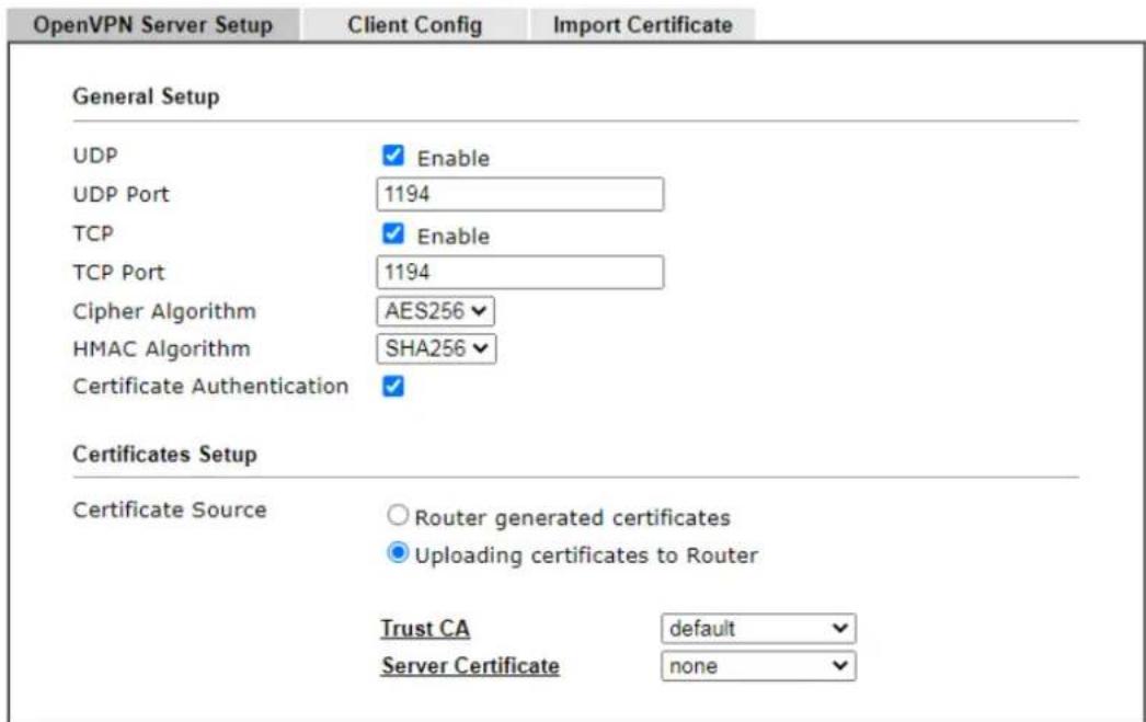
Note: OpenVPN on Vigor Router only support TUN device interface currently. So please setup corresponding configurations on the client side.
OK
Available settings are explained as follows:
| Item | Description |
| General Setup | |
| UDP | Enable - Select checkboxOpenVPN connections.UDP Port - Enter the UDP port number. |
| TCP | Enable - Select checkbcOpenVPN connections.TCP Port - Enter the TCP port number. |
| Cipher Algorithm Select the | desired cipher algorithm. Two encryption algorithms are supported: AES128 and AES256. AES256 is more secure than AES128 but may result in lower performance because it incurs higher computational overhead. |
| HMAC Algorithm HMAC stands | ds for Hash-based Message Authentication Code. It is used to validate the data integrity and authenticity of the VPN data.Select the desired HMAC hash algorithm. Two hash algorithms, SHA1 and SHA256, are supported. SHA256 is preferred as it is more robust and reliable than SHA1. |
| Certificate Authentication | Select this checkbox if you would like to validate that the client certificate was issued by a trusted CA. |
| Certificate Setup | |
| Certificate Source Select a | source for the certificate to be used for OpenVPN. |
| Router generated certificates - Router-generated certificates that will be used for OpenVPN.GENERATE- Click to generate a certificate.Delete all certificates- Click to remove all certificates generated by the router. Uploading certificates to Router- Third-party certificates will be used for OpenVPN.Trust CA- Use the dropdown list to select a trusted CA certificate that has already been uploaded to the router. To upload Trusted CA certificates to the router, click the Trust CA label and you will be taken to the Certificate Management >> Trusted CA Certificate page to perform the operation.Server Certificate- Use the dropdown list to select a server certificate that has already been uploaded to the router. To upload server certificates to the router, click the Server Certificate label and you will be taken to the Certificate Management >> Local Certificate page to perform the operation. |
After finishing all the settings here, please click OK to save the configuration.
III-1-7-2 Client Config
On this page, you can create and export the configuration required for a remote OpenVPN client to connect to the router.
VPN and Remote Access >> OpenVPN

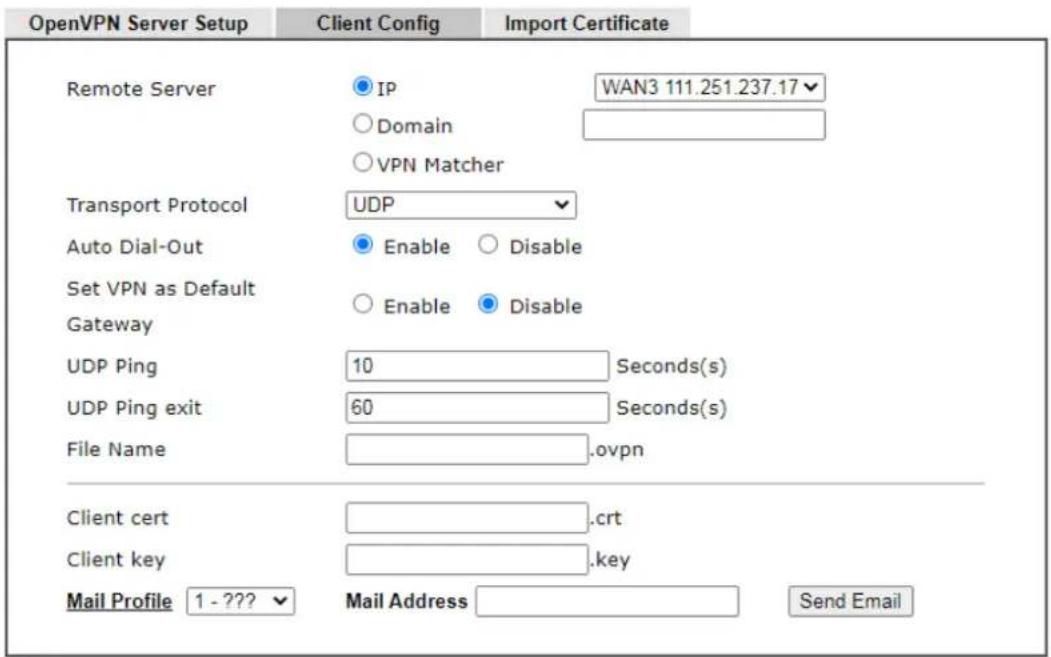
Note:
- Please make sure the Client cert and the Client key are located in the same folder with .ovpn file.
- Please make sure that WAN can be used as OpenVPN server.
Export
Available settings are explained as follows:
| Item | Description |
| Remote Server The OpenVPN | N client will use the IP address or domain name to connect to the router. Select either IP or Domain.IP - The OpenVPN configuration file will use the numeric IP address as the server address.Domain - The OpenVPN configuration file will use the domain as the server address. You need to ensure that the domain resolves to the IP address of a router WAN port.VPN Matcher - The OpenVPN configuration file will use the IP address / URL of VPN matcher server as the remote server. |
| Transport Protocol Select UDP or TCP for the protocol to be used by the OpenVPN client to connect to the router. | |
| Auto Dial-Out Enable - If selected, the remote client can auto-dial to this Vigor router to build an OpenVPN tunnel.Disable - Select to disable the function. | |
| Set VPN as Default Gateway | Enable - If selected, the Vigor router will be treated as a "default" gateway for OpenVPN clients. The OpenVPN client will redirect all the traffic to the Vigor router via theOpenVPN tunnel.Disable - Select to disable the function. |
| UDP Ping | Ping remote device over the UDP control channel, if no packets have been sent for the number of seconds configured here. |
| UDP Ping exit Let OpenVPN | exit after the seconds set here if no reception of a ping or other packet from the remote device. |
| File Name Enter the filename | of the configuration file to be downloaded from the router. |
| Client cert Enter the filename | of the client certificate obtained from 3rd party provider. |
| Client key Enter the filename | of the private key obtained from the 3rd party provider. |
| Mail Profile Use the drop down list to specify a mail profile.Mail Address - Enter the mail address to receive the notification mail.Send Email - Click to send out the mail. | |
| Export | Click this button to download the settings on this page as a file, which can be imported into a VPN client to establish OpenVPN connections. |
III-1-7-3 Import Certificate
On this page, you can import the certificate from other places for a remote OpenVPN client to connect to the router.
VPN and Remote Access >> OpenVPN

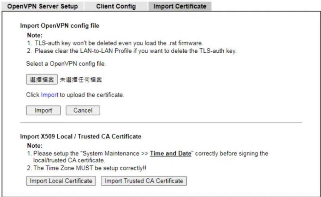
Available settings are explained as follows:
| Item | Description |
| Select an OpenVPN config file | Browse - Click to select a file.Import - Click to import a configuration file. |
| Import Local Certificate Click to access into Local Certificate page for importing a certificate. | |
| Import Trusted CA Certificate | Click to access into Trusted CA Certificate page for importing a certificate. |
III-1-8 WireGuard
WireGuard, at present, is a secure, fast, easy, simple and modern open-source VPN Protocol. By using state-of-the-art cryptography, WireGuard can build a VPN simply by exchanging private and public keys between VPN servers (e.g., Vigor router) and VPN clients (e.g., SmartVPN Client).
VPN and Remote Access >> WireGuard
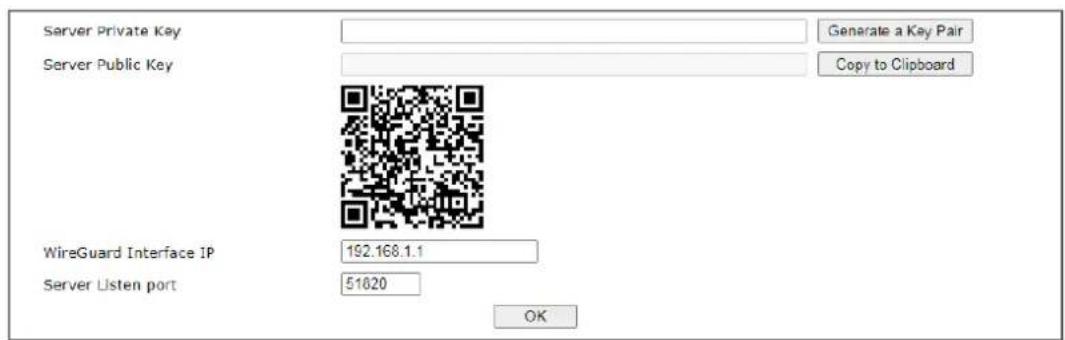
Available settings are explained as follows:
| Item | Description |
| Server Private Key Displays | the private key generated.Generate a Key Pair - Generate keys for the VPN server. |
| Server Public Key It is required to be configured in the WireGuard VPN client router.After clicking Generate a Key Pair, the public key and a QR code representing the public key will be shown on this page.Copy to Clipboard - Click to save the keys as a text file. | |
| WireGuard Interface IP | Enter an IP address. Vigor router's LAN IP can be used as the WireGuard interface IP. |
| Server Listen Port Enter a port number for WireGuard VPN server.The default number is 51820. | |
To save changes on the page, select OK; to discard changes, select Cancel.
III-1-9 Remote Dial-in User
You can manage remote access by maintaining a table of remote user profiles, so that users can be authenticated via VPN connection. Remote dial-in user profiles can be set up on this screen.
VPN and Remote Access >> Remote Dial-in User

| Remote Access User Accounts: | | Set to Factory Default | | ||||||
| View: All Online Offline | Search | ||||||
| Index | Enable | User | Status | Index | Enable | User | Status |
| 1. | ☐ | ??? | --- | 17. | ☐ | ??? | --- |
| 2. | ☐ | ??? | --- | 18. | ☐ | ??? | --- |
| 3. | ☐ | ??? | --- | 19. | ☐ | ??? | --- |
| 4. | ☐ | ??? | --- | 20. | ☐ | ??? | --- |
| 5. | ☐ | ??? | --- | 21. | ☐ | ??? | --- |
| 6. | ☐ | ??? | --- | 22. | ☐ | ??? | --- |
| 7. | ☐ | ??? | --- | 23. | ☐ | ??? | --- |
| 8. | ☐ | ??? | --- | 24. | ☐ | ??? | --- |
| 9. | ☐ | ??? | --- | 25. | ☐ | ??? | --- |
| 10. | ☐ | ??? | --- | 26. | ☐ | ??? | --- |
| 11. | ☐ | ??? | --- | 27. | ☐ | ??? | --- |
| 12. | ☐ | ??? | --- | 28. | ☐ | ??? | --- |
| 13. | ☐ | ??? | --- | 29. | ☐ | ??? | --- |
| 14. | ☐ | ??? | --- | 30. | ☐ | ??? | --- |
| 15. | ☐ | ??? | --- | 31. | ☐ | ??? | --- |
| 16. | ☐ | ??? | --- | 32. | ☐ | ??? | --- |
| << 1-32 | 33-64 | 65-96 | 97-128 | 129-160 | 161-192 | 193-224 | 225-256 | 257-288 | 289-320 | 321- Next >> |
| 352 | 353-384 | 385-416 | 417-448 | 449-480 | 481-500 >> |

Download Smart VPN Client:

Smart VPN Client for Windows

Smart VPN Client for Mobile (Android/iOS)

Smart VPN Client for MacOS
Available settings are explained as follows:
| Item | Description |
| Set to Factory Default Click | to clear all remote-dial-in user profiles. |
| View | All - Click it to display the all of the user accounts.Online - Click it to display the online user accounts.Offline - Click it to display the offline user accounts. |
| Index Click the index number | of the profile the view or edit itssettings. |
| Enable Check to enable the | user profile. |
| User | Display the username for the specific dial-in user of the LAN-to-LAN profile. The symbol ??? represents that the profile is empty. |
| Status Shows the LAN subnet | and IP address assignment method.Example: LAN1-DHCP means that the IP address of the VPN connection will be drawn from the DHCP pool of the LAN1 subnet.The color of the status indicates the current state of the profile:Green - Profile is being used by a dial-in VPN connection.Red - Profile is not being used.Black - Profile is disabled. |
| Backup | Click Backup to save the configuration. |
| Restore | Click Select to choose a configuration file. Then click Restore to apply the file. |
To save changes on the page, select OK; to discard changes, select Cancel.
The following setup screen is shown after a profile index has been clicked.
VPN and Remote Access >> Remote Dial-in User
Index No. 1
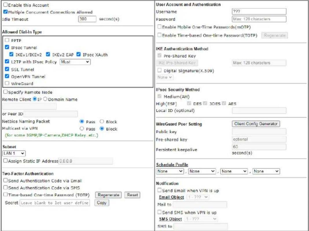
Note:
- Username can not contain characters " and 11
- When your are trying to use OpenVPN tunnel and the router is behind NAT, you may have to enable the VPN-Matcher feature to bypass the NAT.
- VPN-Matcher can only be used behind Cone NAT.
- WireGuard VPN Protocol doesn't support passing Netbios or Multicast packets.

Available settings are explained as follows:
| Item | Description |
| User account and Authentication | Enable this account - Select to enable this profile to be used by remote dial-in users.Multiple Concurrent Connections Allowed - If enabled, multiple VPN clients can connect the VPN server with the username/ password set on this profile.Idle Timeout - Allowed idle time before the router disconnects the VPN connection. Default timeout value is 300 seconds. |
| Allowed Dial-In Type Select | all VPN protocols allowed for this profile.For L2TP, specify how IPsec should be applied. Options are:None- IPsec cannot be used with L2TP connections.Nice to Have- IPsec is preferred but not mandatory for L2TP connections.Must- IPsec is required when establish L2TP connections.Specify Remote Node- The IP address of the remote VPN client (Remote Client IP) or the Peer ID (used in IKE aggressive mode) can be optionally specified. The router will reject the connection if either of these values are entered in the profile but the remote client does not pass the value, or passes the wrong value.Netbios Naming Packet - Specifies whether to allow NetBIOS naming packets to traverse through the VPN tunnel.Pass- Click it to have an inquiry for data transmission between the hosts located on both sides of VPN Tunnel while connecting.Block- When there is conflict occurred between the hosts on both sides of VPN Tunnel in connecting, such function can block data transmission of Netbios Naming Packet inside the tunnel.Multicast via VPN - Specifies whether to allow multicast packets to traverse through the VPN tunnel.Pass- Click this button to let multicast packets pass through the router.Block- This is default setting. Click this button to let multicast packets be blocked by the router. |
| Subnet The VPN client will receive an IP address from the DHCP pool or IP address range specified in IP Address Assignment for Dial-In Users for the selected LAN subnet.Assign Static IP Address - Alternatively, a static IP address can be set by selecting the Assign Static IP Address checkbox. | |
| Two-Factor Authentication | When a remote dal-in user tries to log in Vigor router from the VPN, he/ she has to pass the two-factor authentication.Send Authentication Code via Email - Select to send the authentication code via an e-mail. The e-mail address can be specified in the field of Mail to under the Notification area.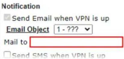 Send Authentication Code via SMS - Select to send the authentication code via an SMS. The telephone number can be specified in the field ofSMS to under theNotification area. Send Authentication Code via SMS - Select to send the authentication code via an SMS. The telephone number can be specified in the field ofSMS to under theNotification area.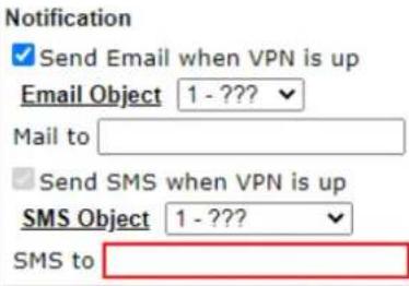 Time-based One-time Password (TOTP) - Select to display a secret generated by Vigor router.Regenerate- Click to regenerate a new secret and corresponding QR code.Reset- Click to clear the secret.Secret- Displays a 32 digit-secret number generated by Vigor router. Correspondign code also will be shown in this area. Time-based One-time Password (TOTP) - Select to display a secret generated by Vigor router.Regenerate- Click to regenerate a new secret and corresponding QR code.Reset- Click to clear the secret.Secret- Displays a 32 digit-secret number generated by Vigor router. Correspondign code also will be shown in this area.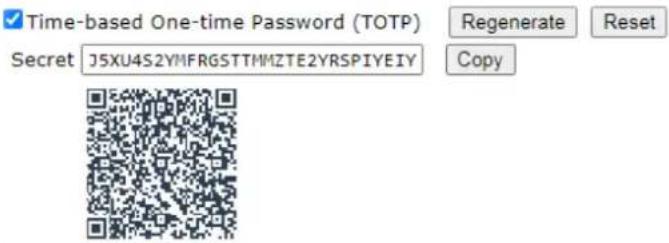 Copy- Click to copy the secret. 但要做甚麼? Copy- Click to copy the secret. 但要做甚麼? |
| User Account and Authentication | User Name- Used for PPTP, L2TP or SSL Tunnel dial-in type. The length of the name is limited to 23 characters.Password- Used for PPTP, L2TP or SSL Tunnel dial-in type. The length of the password is limited to 19 characters.Enable Mobile One-Time Passwords (mOTP) - Select to enable one-time passwords (Mobile-OTP). Enter the PIN Code and Secret. DrayTek's SmartVPN client has built-in support for mOTP. Third-party mOTP clients can be used to generate passwords when using other VPN clients. For more information on mOTP, visit Mobile-OTP's homepage.PIN Code- Enter the code for authentication (e.g, 1234).Secret- Use the 32 digit-secret number generated by mOTP in the mobile phone (e.g., e759bb6f0e94c7ab4fe6).Enable Time-based One-time Password (TOTP) - Please make sure the time zone of your router is correct. Then, install Google Authenticator APP on your cell phone. Openthe APP to scan the QR code on this page. A one-time password will be shown on your phone.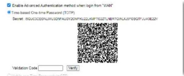 In the filed of Validation Code, enter the one-time password and click Verify. In the filed of Validation Code, enter the one-time password and click Verify.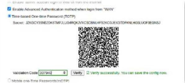 Now, the configuration is finished. You will be asked to enter the 2FA code on the after passing the username and password authentication. Now, the configuration is finished. You will be asked to enter the 2FA code on the after passing the username and password authentication.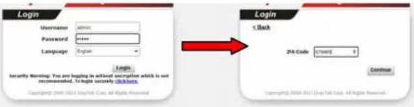 |
| IKE Authentication Method | Pre-Shared Key - This checkbox is available when Remote Client IP or Peer ID is specified. Check the checkbox and click IKE Pre-shared Key to enter an IKE PSK (1~63 characters) that will be used only for this profile.Digital Signature (X.509) - To enable authentication using X.509 Peer IDs, check the checkbox then select an X.509 profile. X.509 profiles can be configured in VPN and Remote Access >> IPsec Peer Identity. |
| IPsec Security Method Select all the IPsec protocols that are allowed to be used for this profile.Medium-Authentication Header (AH) means data will be authenticated, but not be encrypted. By default, this option is invoked. You can uncheck it to disable it.High (ESP) - High-Encapsulating Security Payload (ESP) means payload (data) will be encrypted and authenticated. You may select encryption algorithm from Data Encryption Standard (DES), Triple DES (3DES), and AES.Local ID (Optional)- Specify a local ID to be used when establishing a LAN-to-LAN VPN connection using IKE aggressive mode. | |
| WireGuard Peer Setting Configure the settings for VPN client (peer).Client Config Generator - Click to pop-up the configuration window. | |
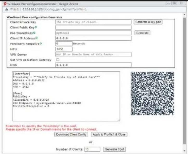 Client Private Key / Client Public Key - Click the Generate a key pair button to generate the private and public keys. The keys will be shown on the corresponding fields.Pre-Shared Key - Displays the value generated by clicking the Generate button.Client IP Address - Enter the static IP address assigned to the client.Persistent Keepalive - Default is 60 seconds. If the peer is behind a NAT or a firewall, use the default setting.MTU - Enter the value. The default is 1412.VPN Server - Enter the public IP address or domain name of Vigor router.Set VPN as Default Gateway - If required, select the box to configure this VPN as the default gateway.DNS - Enter the IP address (e.g., 8.8.8.8) of the DNS server.A QR code will be generated according to the settings configured in this pop-up window. Then, download the x.conf file by clicking Download Client Config and Apply to Profiles & Close.Public Key - Displays the value generated by clicking Client Config Generator.Pre-shared Key - Displays the value generated by clicking Client Config Generator.Persistent Keepalive - Default is 60 seconds. If the peer is behind a NAT or a firewall, use the default setting. Client Private Key / Client Public Key - Click the Generate a key pair button to generate the private and public keys. The keys will be shown on the corresponding fields.Pre-Shared Key - Displays the value generated by clicking the Generate button.Client IP Address - Enter the static IP address assigned to the client.Persistent Keepalive - Default is 60 seconds. If the peer is behind a NAT or a firewall, use the default setting.MTU - Enter the value. The default is 1412.VPN Server - Enter the public IP address or domain name of Vigor router.Set VPN as Default Gateway - If required, select the box to configure this VPN as the default gateway.DNS - Enter the IP address (e.g., 8.8.8.8) of the DNS server.A QR code will be generated according to the settings configured in this pop-up window. Then, download the x.conf file by clicking Download Client Config and Apply to Profiles & Close.Public Key - Displays the value generated by clicking Client Config Generator.Pre-shared Key - Displays the value generated by clicking Client Config Generator.Persistent Keepalive - Default is 60 seconds. If the peer is behind a NAT or a firewall, use the default setting. | |
| Schedule Profile Set the VPN connection to work at certain time interval only.You may choose up to 4 schedules out of the 15 schedules pre-defined in Applications >> Schedule setup. The default setting of this field is blank and the function will always work. | |
| Notification Send Email when VPN is up - An e-mail will be sent to the user defined in Email Object when VPN is connected and up.Mail to - Enter an email address.Send SMS when VPN is up - An SMS will be sent to the user defined in SMS Object when VPN is connected and up. | |
● SMS to - Enter a phone number.
To save changes on the page, select OK; to discard changes, select Cancel; to clear settings on this page and revert to default settings, select Clear.
III-1-10 LAN to LAN
This section allows you to configure up to 500 LAN-to-LAN VPN connection profiles.
LAN-to-LAN connections can be configured to allow dial-in only, dial-out only, or both dial-in and dial-out.
The following figure shows the summary table according to the item (All/ Trunk) selected for View.
VPN and Remote Access >> LAN to LAN

LAN-to-LAN Profiles:
| View: All Online Offline Trunk | Search | ||||||||
| Index | Enable | Name | Remote Network | Status | Index | Enable | Name | Remote Network | Status |
| 1 | ☐ | ??? | --- | 17 | ☐ | ??? | --- | ||
| 2 | ☐ | ??? | --- | 18 | ☐ | ??? | --- | ||
| 3 | ☐ | ??? | --- | 19 | ☐ | ??? | --- | ||
| 4 | ☐ | ??? | --- | 20 | ☐ | ??? | --- | ||
| 5 | ☐ | ??? | --- | 21 | ☐ | ??? | --- | ||
| 6 | ☐ | ??? | --- | 22 | ☐ | ??? | --- | ||
| 7 | ☐ | ??? | --- | 23 | ☐ | ??? | --- | ||
| 8 | ☐ | ??? | --- | 24 | ☐ | ??? | --- | ||
| 9 | ☐ | ??? | --- | 25 | ☐ | ??? | --- | ||
| 10 | ☐ | ??? | --- | 26 | ☐ | ??? | --- | ||
| 11 | ☐ | ??? | --- | 27 | ☐ | ??? | --- | ||
| 12 | ☐ | ??? | --- | 28 | ☐ | ??? | --- | ||
| 13 | ☐ | ??? | --- | 29 | ☐ | ??? | --- | ||
| 14 | ☐ | ??? | --- | 30 | ☐ | ??? | --- | ||
| 15 | ☐ | ??? | --- | 31 | ☐ | ??? | --- | ||
| 16 | ☐ | ??? | --- | 32 | ☐ | ??? | --- | ||

Change default route to None
☐ Pass packets from LAN in Routing mode to VPN
√ Pass Packets to WAN when VPN disconnects

[XXXXXX:This Dial-out profile has already joined for VPN Load Balance Mechanism]
[XXXXXX:This Dial-out profile has already joined for VPN Backup Mechanism]
[XXXXXX:This Dial-out profile does not join for VPN TRUNK]
Available settings are explained as follows:
| Item | Description |
| Set to Factory Default Click | to clear all indexes. |
| View | All - Shows all LAN-to-LAN Trunk - Shows all Trunk profiles (see VPN and Remote Access >> VPN TRUNK Management). |
| Index Click the index number of the profile to view or edit its settings. | |
| Enable Check to enable the LAN-to-LAN VPN profile. | |
| Name | Display the name of the LAN-to-LAN profile. The symbol ??? represents that the profile is empty. |
| Remote Network Display the name of the remote network. | |
| Status Shows the status of the profile. Online - LAN-to-LAN VPN is connected. Offline - LAN-to-LAN VPN is disconnected. --- - Profile is disabled. | |
| Change default route to Select a profile as the default route. | |
| Pass packets from LAN in Routing mode to VPN | If enabled, the packets from routing LAN will pass through the VPN tunnel. |
| Pass Packets to WAN when VPN disconnects | If enabled, the packets can pass through via NAT when the VPN disconnects. |
| Backup | Click Backup to save the configuration. |
| Restore | Click Select to choose a configuration file. Then click Restore to apply the file. |
The following figure shows profiles joined into VPN Load Balance and VPN Backup mechanism.
VPN and Remote Access >> LAN to LAN
LAN-to-LAN Profiles:

[XXXXXX:This Dial-out profile has already joined for VPN Load Balance Mechanism]
[XXXXXX:This Dial-out profile has already joined for VPN Backup Mechanism]
If there is no profile joined yet, this page will be shown as follows:
VPN and Remote Access >> LAN to LAN
LAN-to-LAN Profiles:

[XXXXXX:This Dial-out profile has already joined for VPN Load Balance Mechanism]
[XXXXXX:This Dial-out profile has already joined for VPN Backup Mechanism]
To edit each profile, click each index to edit each profile.
- The setup screen is shown after a profile index has been clicked. There are 6 sections: Common Settings, Dial-Out Settings, Dial-In Settings, Tunnel Settings, 6in4 Settings and TCP/IP Network Settings.
VPN and Remote Access >> LAN to LAN
Profile Index : 1
Common Settings

Dial-Out Settings
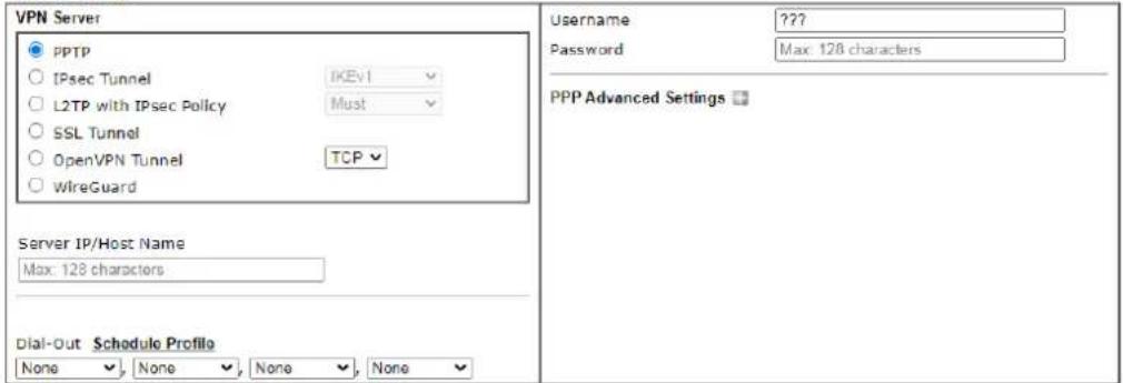
Dial-In Settings
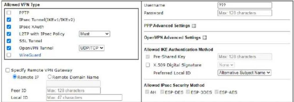
Tunnel Settings

TCP/IP Network Settings


Available settings are explained as follows:
| Item | Description |
| Common Settings | |
| Common Settings Enable | this profile - Check here to activate this profile.Profile Name - Specify a name for the profile of the LAN-to-LAN connection.Call Direction - Specify the allowed call direction of this LAN-to-LAN profile. Four choices are available for connection |
| mode:Both- Profile is to be used to initiate (dial out) or accept (dial in) connections.Dial-Out- Profile is to be used to initiate outgoing connections.Dial-In- Profile is to be used to accept incoming connections.GRE Tunnel- Connection is by means of a GRE tunnel.Dial-Out Through- Use the drop down menu to choose a proper WAN interface for this profile. This setting is useful for dial-out only.WANx First- While connecting, the router will use WANx as the first channel for VPN connection. If WANx fails, the router will use another WAN interface instead.WANx Only- While connecting, the router will use WANx as the only channel for VPN connection.WAN1 Only: Only establish VPN if WAN2 down- If WAN2 failed, the router will use WAN1 for VPN connection.WAN2 Only: Only establish VPN if WAN1 down- If WAN1 failed, the router will use WAN2 for VPN connection.Always On- Select this option to maintain an always on dial-out connection.Idle Timeout- The router will close connection if no activity is observed in the VPN connection for this many seconds. Default value is 300 seconds.Quality Monitoring/Keep Alive- Select this option to keep the VPN connection for the feature of SD-WAN quality monitoring.Netbios Naming Packet- Specifies whether to allow NetBIOS naming packets to traverse through the VPN tunnel.Pass- click it to have an inquiry for data transmission between the hosts located on both sides of VPN Tunnel while connecting.Block- When there is conflict occurred between the hosts on both sides of VPN Tunnel in connecting, such function can block data transmission of Netbios Naming Packet inside the tunnel.Multicast via VPN- Specifies whether to allow multicast packets to traverse through the VPN tunnel.Pass- Click this button to let multicast packets pass through the router.Block- This is default setting. Click this button to let multicast packets be blocked by the router. | |
| Dial-Out Settings | |
| VPN Server Select the IP | VPN protocol to be used. |
| Server IP/Host Name IP | address or DNS host name of remote VPN host. |
| Dial-Out Schedule Profile | Connect and disconnect according to schedule profiles. The default setting of this field is blank and the function will always work. |
| User Name Enter a username for establishing VPN connection. | |
| Password Enter the password for establishing VPN connection. | |
| If PPTP /L2TP with IPsec Policy /SSL Tunnel /is selected as VPN Server | PPP Advanced Settings - Click it to expand the advanced settings for PPP.PPP Authentication -PAP Only - Authenticate dial-in users using the PAP protocol only. PAP/ CHAP/ MS-CHAP/ MS-CHAPv2 -Attempt to authenticate dial-in users using various CHAP protocols, and if the remote VPN client fails to authenticate, fall back to PAP.VJ compression - Specifies whether to enable Van Jacobson (VJ) header compression, which improves throughput on slow connections.Request IP Address - Enter the IP address. |
| If IPsec/ L2TP with IPsec Policy(Must/Nice to Have) is selected as VPN Server | IKE Phase 1 Settings - Select from Main mode and Aggressive mode. The ultimate outcome is to exchange security proposals to create a protected secure channel.Main mode is more secure than Aggressive mode since more exchanges are done in a secure channel to set up the IPsec session. However, the Aggressive mode is faster. The default value in Vigor router is Main mode.Authentication - Digital Signature(X.509)- Peer ID - Select one of the predefined Profiles set in VPN and Remote Access >>IPsec Peer Identity.- Local ID - Use Alternative Subject Name or Subject Name of local certificate as local ID.- Local Certificate - Select one of the profiles set in Certificate Management>>Local Certificate.Authentication - Pre-Shared Key- Pre-Shared Key - Input 1-128 characters as pre-shared key.- Local ID - Enter local IKE identity to send in the exchange to establish IPsec connection.proposal Encryption - Use Auto/ AES/ 3DES/ DES for packet encryption.proposal ECDH Group - Specify a group if Auto is not selected as proposal Encryption.proposal Authentication - Select SHA256 or SHA1 for packet authentication.Force UDP Encapsulation - Select to make UDP encapsulation forcefully. All IPsec packets will be encapsulated with UDP header.IKE Phase 2 Settings - Specify the security protocol, proposal encryption and proposal authentication.Security Protocol - AH (Medium) means data will be authenticated, but not be encrypted. By default, this option is active. ESP (High) means payload (data) will be encrypted and authenticated.Proposal Encryption - Use AES/ 3DES encryption algorithm and apply MD5 or SHA-1 authentication algorithm.Proposal Authentication - Select All, SHA or None.IKE Advanced Settings - Specify the key life of each IKE phase, network ID, etc.IKE phase 1 key lifetime- For security reason, thelifetime of key should be defined. The default value is 28800 seconds. You may specify a value in between 900 and 86400 seconds.IKE phase 2 key lifetime- For security reason, the lifetime of key should be defined. The default value is 3600 seconds. You may specify a value in between 600 and 86400 seconds.Phase 2 Network ID - This is optional. Change the source IP address of VPN traffic to the specified IP address for NAT mode selected on TCP/IP Network Settings field.Enable Perfect Forward Secret (PFS) - The IKE Phase 1 key will be reused to avoid the computation complexity in phase 2. The default value is inactive this function.Ping to Keep Alive - Select to enable the function of PING to keep alive.PING Target IP - Enter the IP address to keep alive. |
| If OpenVPN Tunnel is selected as VPN Server | OpenVPN Advanced Settings - Click to set the advanced settings for OpenVPN.Cipher Algorithm - Select an algorithm for encrypting the packets via OpenVPN.HMAC Algorithm - Select an algorithm for authenticating the packets via OpenVPN.Client Certificate - Select a client certificate or self-signed a new certificate or DrayDDNS certificate.Trust CA - Select a trust CA certificate.Compress - Select a method to compress the packets to reduce the bandwidth usage while transferring the compressed packets.TLS - auth - Select On to use the TLS authentication method. Related key information can be checked by clicking View.Import OpenVPN config file - An OpenVPN config file from other Vigor router can be imported and apply to this router.Select File - Select a file from your hard disk.Import - Click to upload the selected config file to this Vigor router. |
| If WireGuard with is selected as VPN Server | Click WireGuard to set the advanced settings.[Interface] - Configure the settings for Vigor router.Generate a Key Pair - Click to generate a key pair (including private key and public key).Copy to Clipboard - Click to copy the key pair to clipboard.Address - Enter an IP address that Vigor should use to access the remote VPN network.[Peer] - Configure the settings for the client (peer).Public Key - Enter the Public key of the Peer VPN server.Pre-Shared Key - Click Generate to generate the pre-shared key.Keepalive - Default is 60 seconds. |
| Dial-In Settings | |
| Allowed VPN Type | Select permissible VPN protocols for dial-in connections.PPTP - Allow the remote dial-in user to make a PPTP VPN connection through the Internet. You should set the User Name and Password of remote dial-in user below.IPsec Tunnel(IKEv1/IKEv2)- Allow the remote dial-in user to trigger an IPsec VPN connection through Internet.IPsec XAuthL2TP with IPsec Policy - Allow the remote dial-in user to make a L2TP VPN connection through the Internet. You can select to use L2TP alone or with IPsec. Select from below:- None - Do not apply the IPsec policy. Accordingly, the VPN connection employed the L2TP without IPsec policy can be viewed as one pure L2TP connection.- Nice to Have - Apply the IPsec policy first, if it is applicable during negotiation. Otherwise, the dial-in VPN connection becomes one pure L2TP connection.- Must - Specify the IPsec policy to be definitely applied on the L2TP connection.SSL Tunnel- Allow the remote dial-in user to trigger an SSL VPN connection through Internet.OpenVPN TunnelWireGuard - A pop-up window with detailed settings will be shown on the screen. Enter the values if required. |
| Specify Remote VPN Gateway | You can specify the IP address of the remote dial-in user or peer ID (should be the same with the ID setting in dial-in type) by checking the box. Also, you should further specify the corresponding security methods on the right side.If you uncheck the checkbox, the connection type you select above will apply the authentication methods and security methods in the general settings.Usage - This field is applicable when you select PPTP or L2TP with or without IPsec policy above. The length of the name is limited to 11 characters.Password - This field is applicable when you select PPTP or L2TP with or without IPsec policy above. The length of the password is limited to 11 characters. |
| PPP Advanced Settings | Click it to expand the advanced settings for PPP.VJ Compression - Specifies whether to enable Van Jacobson header compression, which improves throughput on slow connections.Assign Peer IP Address - Enter the IP address of the peer. |
| OpenVPN Advanced Settings | Cipher Algorithm - Select an algorithm for encrypting the packets via OpenVPN.HMAC Algorithm - Select an algorithm for authenticating the packets via OpenVPN. |
| Allowed IKE Authentication Method | This section is available when IPsec tunnel is selected as the dial-out protocol. Available options are IKE Pre-shared key and X.509 digital signature.Pre-Shared Key - To use a pre-shared key, select this radio-button and then click the IKE Pre-Shared Key button to enter the PSK.X.509 Digital Signature - To use an X.509 digital signature, select this radio button and then select an X.509 IPsec Peer Identity profile. To enable authentication using X.509 Peer IDs. X.509 profiles can be configured inVPN and Remote Access >> IPsec Peer Identity.Local ID - Select whether to first match Subject Alternative Name or Subject Name during authentication.-Alternative Subject Name - The alternative subject name (configured inCertificate Management>>Local Certificate) will be inspected first.-Subject Name - The subject name (configured inCertificate Management>>Local Certificate) will be inspected first. |
| Allowed IPsec Security Method | This setting is available when IPsec Tunnel is selected as the dial-out protocol.AH- Authentication Header (AH) means data will be authenticated, but not be encrypted. Select to use Authentication Header protocol. By default, this option is active.ESP-DES/ESP-3DES/ESP-AES - Encapsulating Security Payload (ESP) means payload (data) will be encrypted and authenticated. You may select encryption algorithm from Data Encryption Standard (DES), Triple DES (3DES), and AES. |
| Tunnel Settings | |
| Enable IPsec Dial-Out function GRE over IPsec | Check this box to verify data and transmit data in encryption with GRE over IPsec packet after configuring IPsec Dial-Out setting. Both ends must match for each other by setting same virtual IP address for communication. |
| Logical Traffic | Such technique comes from RFC2890. Define logical traffic for data transmission between both sides of VPN tunnel by using the characteristic of GRE. Even hacker can decipher IPsec encryption, he/she still cannot ask LAN site to do data transmission with any information. Such function can ensure the data transmitted on VPN tunnel is really sent out from both sides. This is an optional function. However, if one side wants to use it, the peer must enable it, too. |
| Tunnel Local IP | Enter the virtual IP for router itself for verified by peer. |
| Tunnel Remote IP | Enter the virtual IP of peer host for verified by router. |
| TCP/IP Network Settings | |
| Local Network The default value is 0.0.0.0, which means the Vigor router will get a PPP IP address from the remote router during the IPCP negotiation phase. If the PPP IP address is fixed by remote side, specify the fixed IP address here. Do not change the default value if you do not select PPTP or L2TP.IP / Mask - Display the local network IP and mask for TCP / IP | |
| configuration. You can modify the settings if required. | |
| Remote Network The default value is 0.0.0.0, which means the Vigor router will get a remote Gateway PPP IP address from the remote router during the IPCP negotiation phase. If the PPP IP address is fixed by remote side, specify the fixed IP address here. Do not change the default value if you do not select PPTP or L2TP.IP/ Mask - Add a static route to direct all traffic destined to this Remote Network IP Address/ Remote Network Mask through the VPN connection. For IPsec, this is the destination clients IDs of phase 2 quick mode. | |
| More Remote Subnet Click to bring up a dialog box to enter additional static routes for subnets destined for the remote network.More Remote SubnetW2Y6] | |
| Mode | If the remote network only allows one IP address for the local network, select NAT; otherwise, selectRouting. |
| When the Mode is set to Routing | WhenRoutingis selected, the available fields in the TCP/IP Network Settings section will be shown as:Translate Local Network- Check the box to enable the function. Add a static route to direct all traffic destined to more Remote Network IP Addresses/ Remote Network Mask through the VPN connection. This is usually used when you find there are several subnets behind the remote VPN router.Type- There are two types (Translate Whole Subnet, Translate Specific IP) for you to choose.WhenTranslate Whole Subnetis selected asType, available settings are listed as below:TypeTranslate Whole SubnetLocal SubnetLAN1Translated IP192.168.1.0More Local SubnetLocal NetworkLAN1Translated to0.0.0.0AddDeleteEdit-Local Subnet- Select the LAN whose IP addresses are to be translated.-Translated IP- Specify an IP address.-More Local Subnet- Click it to add more subnets. WhenTranslate Specific IPis selected asType, available settings are listed as below: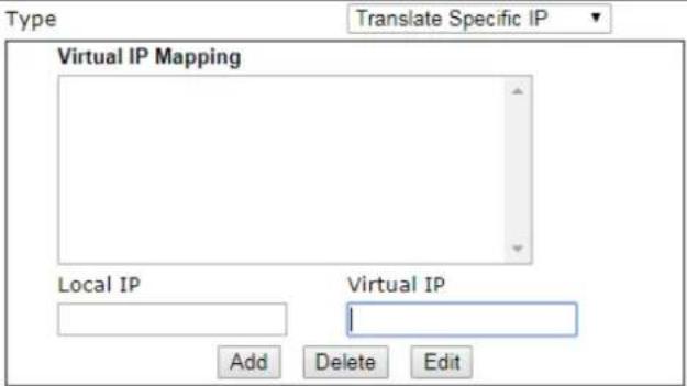 -Virtual IP Mapping- A pop up dialog will appear for you to specify the local IP address and the mapping virtual IP address. -Virtual IP Mapping- A pop up dialog will appear for you to specify the local IP address and the mapping virtual IP address. |
| When the Mode is set to NAT | When NATis selected, the available fields in the TCP/IP Network Settings section will be shown as:RIP via VPN- Specifies the direction of Routing Information Protocol (RIP) packets. Available options are:TX/ RX Both - can transmit or receive RIP packetsTX Only - can only transmit but not receive RIP packetsRX Only - can only receive but not transmit RIP packetsDisable - RIP is disabled.Change Default Route to this VPN tunnel- Select this option to direct all traffic that is not LAN-bound to this VPN tunnel. This option is functional when there is only one active WAN. |
- To save changes on the LAN to LAN profile page, select OK; to reset the entire page to blank, select Clear; to discard changes, select Cancel.
III-1-11 VPN Trunk Management
A VPN Trunk combines TWO LAN-to-LAN VPN tunnels to provide VPN Backup or VPN Load Balance functionalities.
VPN Backup
VPN Backup provides redundant, uninterrupted VPN connectivity by constantly monitoring the health of a VPN tunnel, and fails over to the secondary VPN tunnel when the primary tunnel fails.
In a Backup VPN Trunk, only one of the two LAN-to-LAN VPN tunnels is connected at any given time. When one tunnel fails, the router will automatically start up and direct all VPN traffic destined for the trunk to the other tunnel.
VPN Load Balance
VPN Load Balance increases the bandwidth of a LAN-to-LAN connection by combining and load balancing two tunnels, with the option to direct traffic to specific tunnels by originating address, destination address or port.
In a Load Balance VPN Trunk, both LAN-to-LAN VPN tunnels are simultaneously connected. The router first attempts to match the traffic to a load balance policy rule and send it down the tunnel specified in the matching rule. Traffic not matched to any policy will be load balanced in a round-robin fashion, and the traffic ratio between the two tunnels is either determined automatically by the router or specified by the user.
In order to set up a VPN Trunk, 2 LAN-to-LAN VPN profiles must have been configured first. For details on the configuration of LAN-to-LAN VPN tunnels, see section V-1-10 LAN to LAN. When the 2 LAN-to-LAN VPN profiles are ready, follow the steps below to set up a VPN Trunk.
Creating a VPN Trunk
To create a new VPN Trunk, configure the General Setup section first.
![Backup Profile List Set to Factory Default Note: [Active:NO] The LAN-to-LAN Profile is disabled or under Dial-In(Call Direction) at present. No. Status Name Member1(Active)Type Member2(Active)Type Advanced](/content/2026/05/813922/images/05a9061ba53580eb17dbec6a60007dff1223032a7ddc72c220dfbaff7a92a834.jpg)
![Load Balance Profile List Set to Factory Default Note: [Active:NO] The LAN-to-LAN Profile is disabled or under Dial-In(Call Direction) at present. No. Status Name Member1(Active)Type Member2(Active)Type Advanced](/content/2026/05/813922/images/6c25816ce5fdb7c5a367ab1ae594d28557185a9ff85c7432b21b6f7afbf90e9c.jpg)

Add Update Delete
Available settings are explained as follows:
| Item | Description |
| General Setup Status - Enable or disable the VPN Trunk.● Enable - Select this to enable this VPN trunk.● Disable - Select this to disable this VPN trunk.Profile Name - Enter a name to identify this VPN Trunk profile.Member 1/Member2 - Select LAN-to-LAN VPN profiles to be the first and second members of this VPN Trunk.Active Mode - Select the operation mode of the VPN Trunk.Backup / Load Balance - Select this to set up a Backup / Load Balance VPN Trunk.Add - Select it to add a VPN Trunk Profile using the entered information.Update - Select it to save the changes to the Status (Enable or Disable), profile name, member1 or member2.Delete - Select it to delete the selected VPN TRUNK profile. The corresponding members (LAN-to-LAN profiles) grouped in the deleted VPN TRUNK profile will be released and that profiles in LAN-to-LAN will be displayed in black. | |
Configuring, Modifying or Deleting a VPN Trunk
To configure or modify a VPN Trunk, go to the Profile List section that corresponds to the type of the VPN trunk (Backup or Load Balance).
VPN and Remote Access >> VPN TRUNK Management

![Backup Profile List Set to Factory Default Note: [Active:NO] The LAN-to-LAN Profile is disabled or under Dial-In(Call Direction) at present. No. Status Name Member1(Active)Type Member2(Active)Type Advanced](/content/2026/05/813922/images/e07101dd6f32b70478067468c931d4834ca4aba5c559a20b052749c554b480f6.jpg)
![Load Balance Profile List Set to Factory Default Note: [Active:NO] The LAN-to-LAN Profile is disabled or under Dial-In(Call Direction) at present. No. Status Name Member1(Active)Type Member2(Active)Type Advanced](/content/2026/05/813922/images/9f9d10a7f2813a52c18b82a0a52441b89169d7f3586e1544d471e05ae69614c6.jpg)


Available settings are explained as follows:
| Item | Description |
| Backup Profile List andLoad Balance Profile List | Set to Factory Default - Removes all VPN Trunk profiles in the Profile List.No. - The index number of VPN profile.Status - Shows whether the VPN Trunk is enabled or disabled.v - VPN Trunk is enabled.x - VPN Trunk is disabled.Name - The user-entered name that identifies the trunk profile.Member1 (Active) Type / Member2 (Active) Type - Shows the profile index, whether it is enabled or disabled, and the VPN protocol of the 2 LAN-to-LAN VPN profiles.Example: 1(YES)PPTP - the trunk member is set to use the first profile which is currently enabled and uses the PPTP protocol.Advanced - To configure advanced settings of a VPN Trunkprofile, select its name from the dropdown list and click Advanced. |
| Advanced for Backup Profile List | If a Backup Profile was selected, the following Advanced Settings screen appears: 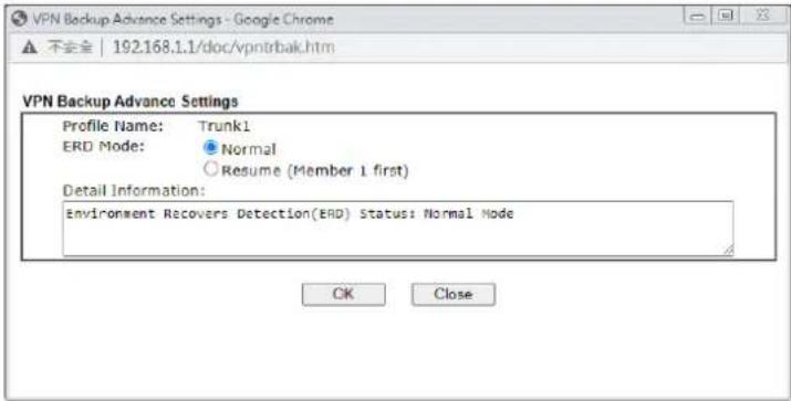 Profile Name - User-defined name that identifies this profile.ERD Mode - Sets the Environment Recovery Detection (ERD) mode. Normal - Both VPN tunnels have equivalent priority. Resume - Member 1 and Member 2 VPN tunnels are primary and secondary connections, respectively. The router will always attempt to use Member 1 first, and only fail over to Member 2 if Member 1 is down.Detail Information - Provides a detailed explanation of the ERD mode.To save Advanced Settings for the profile, select OK; to close without saving changes, select Close. Profile Name - User-defined name that identifies this profile.ERD Mode - Sets the Environment Recovery Detection (ERD) mode. Normal - Both VPN tunnels have equivalent priority. Resume - Member 1 and Member 2 VPN tunnels are primary and secondary connections, respectively. The router will always attempt to use Member 1 first, and only fail over to Member 2 if Member 1 is down.Detail Information - Provides a detailed explanation of the ERD mode.To save Advanced Settings for the profile, select OK; to close without saving changes, select Close. |
| Advanced for Load Balance Profile List | If a Load Balance Profile was selected, the following Advanced Settings screen appears: 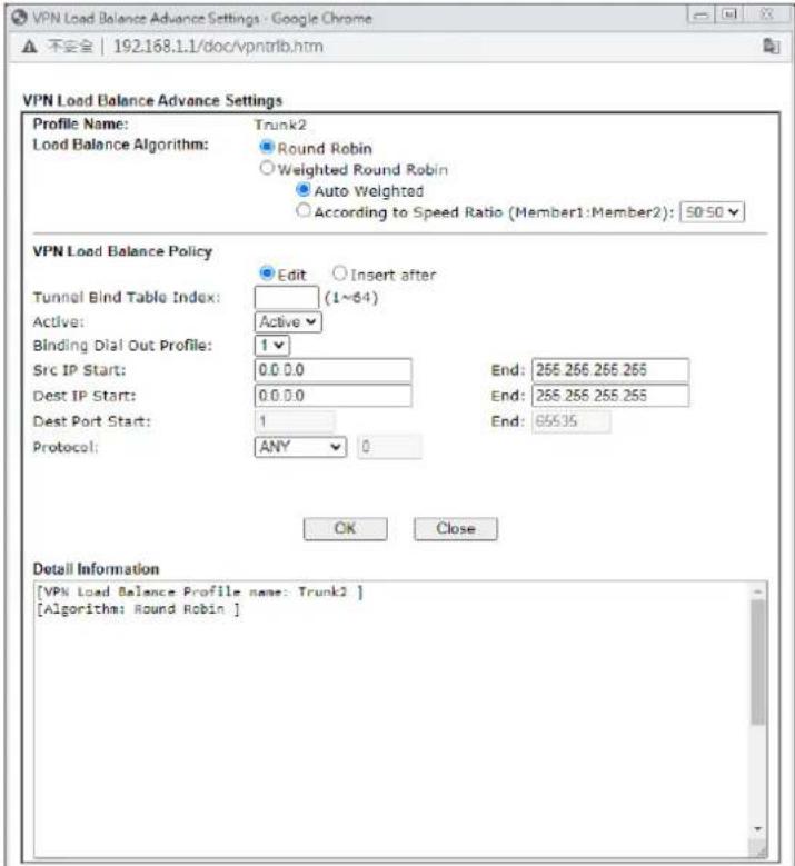 Profile Name - User-defined name that identifies thisprofile.Load Balance Algorithm - Configures how load balancing is performed.● Round Robin - All outgoing connections that do not match to any load balance policy are evenly distributed between the tunnels.● Weighted Round Robin -- All outgoing connections that do not match to any load balance policy are distributed between the tunnels based on a ratio that is either automatically determined by the router (Auto Weighted), or specified by the user (According to Speed Ratio).VPN Load Balance Policy - This section allows the modification or addition of load balance policy profiles.Edit / Insert After - Select Edit to modify the existing load balance profile with index specified in Tunnel Bind Table Index, or Insert After to insert a new load balance profile immediately after the index position specified in Tunnel Bind Table Index.Tunnel Bind Table Index- 64 Binding tunnel tables are provided by this device. In Edit mode, the profile that matches this index will be updated.In Insert After mode, a new profile will be inserted immediately after the policy having this index.Active - Includes Active and Clear. In which,● Active - All information will be saved into a load balance profile.● Clear - The profile with index matching Tunnel Bind Table Index will be deleted.Binding Dial Out Profile - The LAN-to-LAN VPN tunnel to which traffic matching this policy will be sent.Scr IP Start /End- Specify source IP addresses as starting point and ending point.Dest IP Start/End - Specify the target IP addresses as starting point and ending point.Dest Port Start /End- Specify the target port range if the protocol is TCP or UDP.Protocol - Specify the protocol of the traffic.Detail Information - Shows all the information about the Load Balance profile.To save Advanced Settings for the profile, select OK; to close without saving changes, select Close. Profile Name - User-defined name that identifies thisprofile.Load Balance Algorithm - Configures how load balancing is performed.● Round Robin - All outgoing connections that do not match to any load balance policy are evenly distributed between the tunnels.● Weighted Round Robin -- All outgoing connections that do not match to any load balance policy are distributed between the tunnels based on a ratio that is either automatically determined by the router (Auto Weighted), or specified by the user (According to Speed Ratio).VPN Load Balance Policy - This section allows the modification or addition of load balance policy profiles.Edit / Insert After - Select Edit to modify the existing load balance profile with index specified in Tunnel Bind Table Index, or Insert After to insert a new load balance profile immediately after the index position specified in Tunnel Bind Table Index.Tunnel Bind Table Index- 64 Binding tunnel tables are provided by this device. In Edit mode, the profile that matches this index will be updated.In Insert After mode, a new profile will be inserted immediately after the policy having this index.Active - Includes Active and Clear. In which,● Active - All information will be saved into a load balance profile.● Clear - The profile with index matching Tunnel Bind Table Index will be deleted.Binding Dial Out Profile - The LAN-to-LAN VPN tunnel to which traffic matching this policy will be sent.Scr IP Start /End- Specify source IP addresses as starting point and ending point.Dest IP Start/End - Specify the target IP addresses as starting point and ending point.Dest Port Start /End- Specify the target port range if the protocol is TCP or UDP.Protocol - Specify the protocol of the traffic.Detail Information - Shows all the information about the Load Balance profile.To save Advanced Settings for the profile, select OK; to close without saving changes, select Close. |
| Add Select it to add a VPN Trunk Profile using the entered information. | |
| Update Make modifications as necessary in the General Setup section.Select it to save the changes to the Status (Enable or Disable), profile name, member1 or member2. | |
| Delete Select it to remove the VPN TRUNK profile.The corresponding members (LAN-to-LAN profiles) grouped in the deleted VPN TRUNK profile will be released and that profiles in LAN-to-LAN will be displayed in black. | |
III-1-12 Connection Management
You can find the summary table of all VPN connections. You may disconnect any VPN connection by clicking Drop button. You may also aggressively Dial-out by using Dial-out Tool and clicking Dial button.
VPN and Remote Access >> Connection Management

VPN Connection Status

□No subpaging □No auto refreshing
\~\~\~\~\~\~: Data is encrypted. \~\~\~\~\~\~: Data isn't encrypted. \~\~\~\~\~\~: Waiting Client 2FA.
Available settings are explained as follows:
| Item | Description |
| Refresh Click to manually reload the page to refresh VPN connection information. | |
Dial-out Tool The Dial-out Tool section can be used to initiate outgoing LAN-to-LAN VPN sessions.General Mode - It lists all LAN-to-LAN VPN profiles that do not belong to enabled VPN Trunk profiles.To manually dial a LAN-to-LAN VPN profile, select it from the combo box, and click the Dial button to the right. The VPN connection built by General Mode does not support VPN backup function.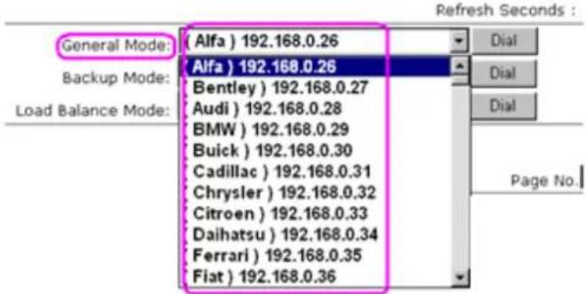 Backup Mode - It lists all Backup VPN Trunk profiles. To manually dial a Backup VPN Trunk profile, select it from the combo box, and click the Dial button to the right. The VPN connection built by Backup Mode supports VPN backup function.General Mode: (Alfa) 192.168.0.26DalBackup Mode: (VpnBackup) 192.168.2.103DalLoad Balance Mode: (VpnBackup) 192.168.2.103DalLoad Balance Mode - It lists all Load Balance VPN Trunk profiles. To manually dial a Load Balance VPN Trunk profile, Backup Mode - It lists all Backup VPN Trunk profiles. To manually dial a Backup VPN Trunk profile, select it from the combo box, and click the Dial button to the right. The VPN connection built by Backup Mode supports VPN backup function.General Mode: (Alfa) 192.168.0.26DalBackup Mode: (VpnBackup) 192.168.2.103DalLoad Balance Mode: (VpnBackup) 192.168.2.103DalLoad Balance Mode - It lists all Load Balance VPN Trunk profiles. To manually dial a Load Balance VPN Trunk profile, | |
| select it from the combo box, and click theDialbutton to the right.Dial- Click this button to execute dial out function. If the connect is successfully made, it will show up in the VPN Connection Status section below. | |
| VPN Connection Status VPN | - Displays the VPN profile number and the profile name.Type- Displays the VPN protocol used for the connectionRemote IP- Displays the remote IP address of the VPN connection.Virtual Network- Displays the IP subnet used by the VPN connection.Tx Pkts- Displays the number of packets that have been transmitted through the VPN connection.Tx Rate(Bps)- Displays the current upstream speed of the VPN connection.Rx Pkts- Displays the number of packets that have been received through the VPN connection.Rx Rate(Bps)- Displays the current downstream speed of the VPN connection.UpTime- Displays the elapsed time of the VPN connection.Drop- Click this button to disconnect this VPN connection. |
Application Notes
A-1 How to Build a LAN-to-LAN VPN Between Remote Office and Headquarter via IPsec Tunnel (Main Mode)
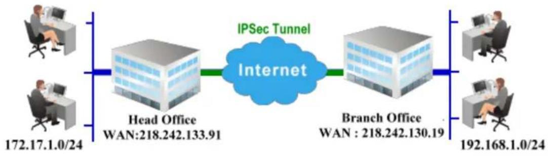
flowchart
graph LR
    A["Head Office<br>WAN:218.242.133.91"] --> B["Internet"]
    C["Branch Office<br>WAN: 218.242.130.19"] --> B
    D["Client 172.17.1.0/24"] --> A
    E["Client 192.168.1.0/24"] --> C
    F["Client 172.17.1.0/24"] --> D
    G["Client 192.168.1.0/24"] --> E
    H["Client 172.17.1.0/24"] --> I["Client 192.168.1.0/24"]
Configuration on Vigor Router for Head Office
- Log into the web user interface of Vigor router.
- Open VPN and Remote Access>>LAN to LAN to create a LAN-to-LAN profile. The following settings are for a permanent VPN connection.
VPN and Remote Access >> LAN to LAN

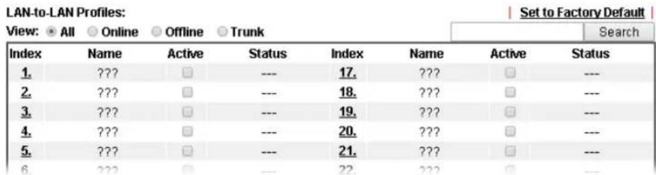
- Click any index number to open the configuration page. Type a name which is easy for identification for such profile (in this case, type VPN Server), and check the box of Enable This Profile. For Vigor router will be set as a server, the call direction shall be set as Dial-in and set 0 as Idle Timeout.
VPN and Remote Access >> LAN to LAN
Profile Index : 1
- Common Settings
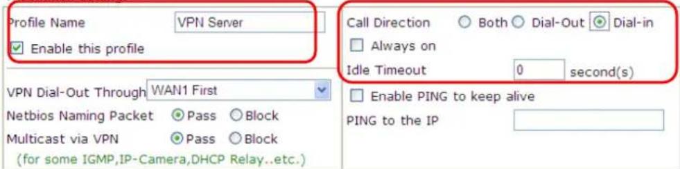
-
Dial-Out Settings
-
Now navigate to the next section, Dial-In Settings to check PPTP, IPsec Tunnel and L2TP boxes. Check the box of Specify Remote... and type the Peer VPN Server IP (e.g., 218.242.130.19 in this case). Press the IKE Pre-Shared Key button to set the PSK; and select Medium (AH) or High (ESP) as the security method.
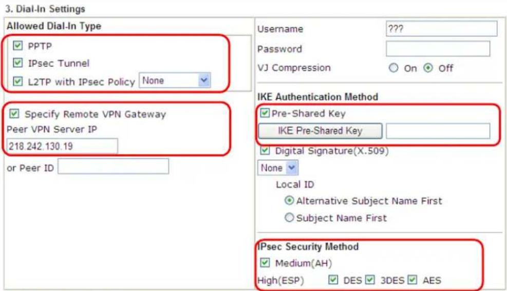
-
Gre over IPsec Settings
-
Continue to navigate to the TCP/IP Network Settings for setting the LAN IP for remote side.

- Click OK to save the settings.
- Open VPN and Remote Access>>Connection Management to check the dial-in connection status (from branch office).
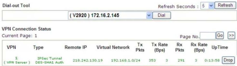
xxxxxxxx: Data is encrypted. xxxxxxxx: Data isn't encrypted.
Configuration on Vigor Router for Branch Office
- Log into the web user interface of Vigor router.
- Open VPN and Remote Access>>LAN to LAN to create a LAN-to-LAN profile. The following settings are for a permanent VPN connection.
VPN and Remote Access >> LAN to LAN

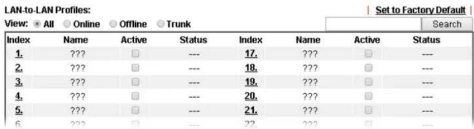
- Click any index number to open the configuration page. Type a name which is easy for identification for such profile (in this case, type VPN Client), and check the box of Enable This Profile. For such Vigor router will be set as a client, the call direction shall be set as Dial-out. Check the box of Always on for a permanent VPN connection.
VPN and Remote Access >> LAN to LAN
Profile Index : 1
- Common Settings
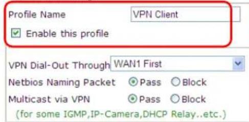
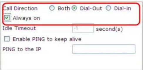
-
Dist Out Settings
-
Now navigate to the next section, Dial-Out Settings to select the IPsec Tunnel service and type the remote server IP/host name (e.g., 218.242.133.91, in this case). Press the IKE Pre-Shared Key button to set the PSK; and select Medium (AH) or High (ESP) as the security method.
2. Dial-Out Settings
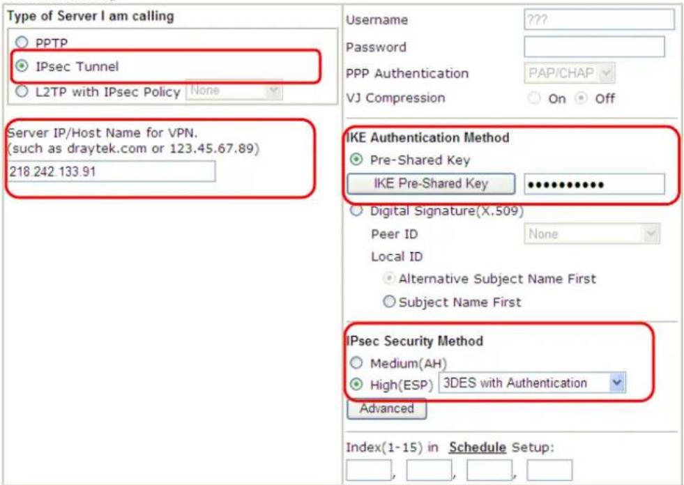
- Continue to navigate to the TCP/IP Network Settings for setting the LAN IP for the remote side.
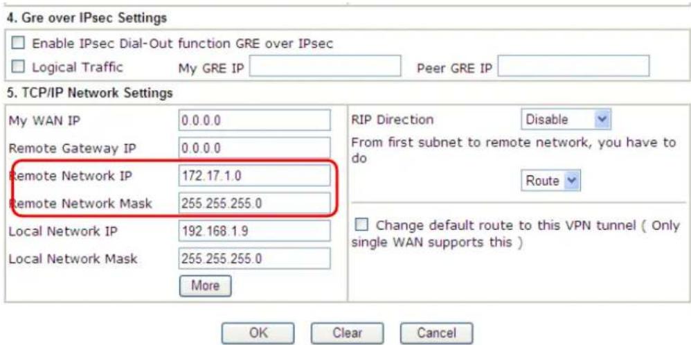
-
Click OK to save the settings.
-
Open VPN and Remote Access>>Connection Management to check the dial-in connection status (from head office).
VPN and Remote Access >> Connection Management

VPN Connection Status
Current Page: 1
| VPN | Type | Remote IP | Virtual Network | Tx Pkts | Tx Rate (Bps) | Rx Pkts | Rx Rate (Bps) | UpTime |
| 1 (VPN Client) | IPSec Tunnel DES-SHA1 Auth | 218.242.133.91 | 172.17.1.0/24 | 8 | 3 | 132 | 36 0:6:41 | Drop |
xxxxxxxxx : Data is encrypted.
xxxxxxxx : Data isn't encrypted.
III-2 Certificate Management
A digital certificate is an electronic document issued by a certification authority (CA) to an entity to prove ownership of a public key. It contains identifying information including the issued-to-party's name, a serial number, expiration dates etc., and the digital signature of the certificate-issuing authority so that a recipient can verify that the certificate is real. Vigor router supports digital certificates that conform to the X.509 standard.
In this section, you can generate and manage local digital certificates, and import trusted CA certificates. Be sure that the system time is correct on the router so that certificates will not be erroneously considered to be invalid because of an incorrect system time falling outside of the certificate's valid time period. The easiest way to accomplish this is by periodically synchronizing the system time to a Network Time Protocol (NTP) server.
Web User Interface
Certificate Management
Local Certificate
Trusted CA Certificate
Certificate Backup
Self-Signed Certificate
III-2-1 Local Certificate
You can generate, import or view local certificates on this page.
Certificate Management >> Local Certificate
X509 Local Certificate Configuration
| Name | Subject | Status | Modify | |
| DrayDDNS (Global) | /CN=faeallen3910.drayddns.com | OK | View | Delete |
| --- | --- | --- | View | Delete |
| --- | --- | --- | View | Delete |
Note:
- Please setup the "System Maintenance >> Time and Date" correctly before signing the local/trusted CA certificate.
- The Time Zone MUST be setup correctly!!
GENERATE IMPORT REFRESH
Available settings are explained as follows:
| Item | Description |
| Name Displays the Name that identifies the certificate. | |
| Subject Displays the Subject Name entries of the certificate. | |
| Status Displays the status of the certificate. Status is one of Requesting. | |
| Modify View - Click to view details about the certificate. A screen that looks like the following will be displayed, showing the Subject Name, Subject Alternative Name, and the certificate content. | |
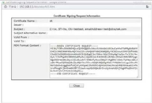 Delete - Click to remove the certificate. Delete - Click to remove the certificate. | |
| Generate | Click to fill out details about a certificate, and start the generation process. |
| Import Click to update an | existing certificate. |
| Refresh Click to refresh the | page to display the latest certificate information. |
GENERATE
Use this screen to submit a request to your root CA to generate a certificate.
Certificate Management >> Local Certificate
Generate Certificate Signing Request
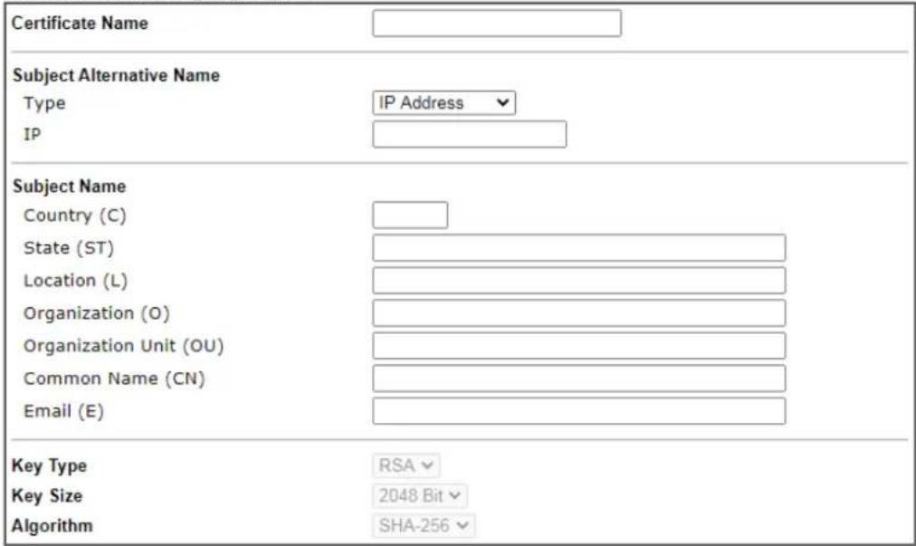
Generate
Available settings are explained as follows:
| Item | Description |
| Certificate Name Name that identifies the certificate. | |
| Type Select the type of Subject Alternative Name and enter its value. | |
| Country (C) Country in which your organization is located. | |
| State (ST) State or province where your organization is located. | |
| Location (L) City where you're your organization is located. | |
| Organization (O) Legal name of your organization. | |
| Organization Unit (OU) | Department within your organization that you wish to be associated with this certificate. |
| Common Name (CN) | Fully-qualified domain name / WAN IP that will be used to reach your server. |
| Email (E) Email address of the entry. | |
| Key Type Key type is hard set to RSA. | |
| Key Size Choose between 1024 and 2048 bit. | |
| Algorithm Choose between SHA-1 and SHA-256. | |
| Generate Click to submit generate request to the CA server. | |

Info
Please be noted that "Common Name" must be configured with rotuer's WAN IP or domain name.
After clicking the Generate button, you will be taken back to the main Local Certificate screen, showing the certificate request in progress:
Certificate Management >> Local Certificate
X509 Local Certificate Configuration
| Name | Subject | Status | Modify | |
| server | /C=TW/ST=Hsinchu/L=Hsinchu/O... | Requesting | View | Delete |
| --- | --- | --- | View | Delete |
| --- | --- | --- | View | Delete |

IMPORT
Vigor router allows you to generate a certificate request and submit it the CA server, then import it as "Local Certificate". If you have already gotten a certificate from a third party, you may import it directly. The supported types are PKCS12 Certificate and Certificate with a private key.
Click this button to import a saved file as the certification information. There are three types of local certificate supported by Vigor router.
Import X509 Local Certificate
Upload Local Certificate
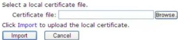
Upload PKCS12 Certificate
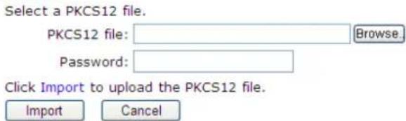
Upload Certificate and Private Key
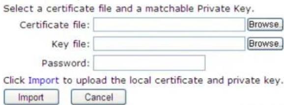
Available settings are explained as follows:
| Item | Description |
| Upload Local Certificate | Certificate file - Click Browse to select a local certificate file.Import - Click to import selected certificate file to router.Cancel - Click to return to the main Local Certificate screen.If you have done well in certificate generation, the Status of the certificate will be shown as “OK”.Import X509 Local CertificateCongratulation!Local Certificate has been imported successfully.Please click Back to view the certificate.X509 Local Certificate ConfigurationName Subject Status Modifydraytekdemo /O=Draytek/OU=Draytek Sales/... OK View Delete.... --- --- --- View Delete.... --- --- --- View DeleteGENERATE IMPORT REFRESH |
| Upload PKCS12 Certificate | It allows users to import the certificate whose extensions are usually .pfx or .p12. And these certificates usually need passwords.Note that PKCS12 is a standard for storing private keys and certificates securely. It is used in (among other things) Netscape and Microsoft Internet Explorer with their import and export options.PKCS12 file - Click Browse to select a PKCS12 certificate file.Password - Enter the password associated with the certificate and key files.Import - Click to import selected certificate file to router.Cancel - Click to return to the main Local Certificate screen. |
| Upload Certificate and Private Key | It is useful when users have separated certificates and private keys. And the password is needed if the private key is encrypted.Certificate file - Click Browse to select a local certificate file.Key file -Password - Enter the password associated with the certificate and key files.Import - Click to import selected certificate file to router.Cancel - Click to return to the main Local Certificate screen. |
If the import was successful, you will see the following confirmation screen:
Import X509 Local Certificate
Congratulation!
Local Certificate has been imported successfully.
Please click Back to view the certificate.
X509 Local Certificate Configuration
| Name | Subject | Status | Modify | |
| draytekdemo | /O=Draytek/OU=Draytek Sales/... | OK | View | Delete |
| --- | --- | --- | View | Delete |
| --- | --- | --- | View | Delete |

REFRESH
Click this button to refresh the information listed below.
III-2-2 Trusted CA Certificate
Trusted CA certificate lists three sets of trusted CA certificate. In addition, you can build a RootCA certificate if required.
When the local client and remote client are required to make certificate authentication (e.g., IPsec X.509) for data passing through SSL tunnel and avoiding the attack of MITM, a trusted root certificate authority (Root CA) will be used to authenticate the digital certificates offered by both ends.
However, the procedure of applying digital certificate from a trusted root certificate authority is complicated and time-consuming. Therefore, Vigor router offers a mechanism which allows you to generate root CA to save time and provide convenience for general user. Later, such root CA generated by DrayTek server can perform the issuing of local certificate.

Info
Root CA can be deleted but not edited. If you want to modify the settings for a Root CA, please delete the one and create another one by clicking Create Root CA.
You can create, import and view root and trusted certificate authority certificates on this screen.
Certificate Management >> Trusted CA Certificate
X509 Trusted CA Certificate Configuration
| Name | Subject | Status | Modify |
| --- | --- | Create Root CA | |
| Trusted CA-1 | --- | --- | View Delete |
| Trusted CA-2 | --- | --- | View Delete |
| Trusted CA-3 | --- | --- | View Delete |
Note:
- Please setup the "System Maintenance >> Time and Date" correctly before you try to generate a RootCA!!
- The Time Zone MUST be setup correctly!!
IMPORT
REFRESH
Available settings are explained as follows:
| Item | Description |
| Name Name that identifies the certificate. | |
| Subject | Shows the Subject Name of the certificate. |
| Status Displays the status of the certificate. | |
| Modify Create Root CA - Click to fill out details about a certificate, and start the generation process.View - Click to view details of the certificate. | |
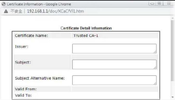 Delete - Click to delete the certificate. Delete - Click to delete the certificate. | |
| Import Click to import an existing certificate. | |
| Refresh Click to refresh the page to display the latest certificate information. | |
Creating a RootCA
Click Create Root CA to open the following page.
Certificate Management >> Root CA Certificate
Generate Root CA
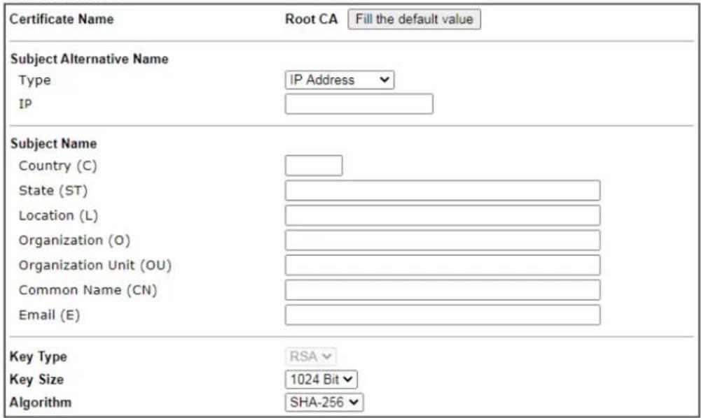
Generate
Available settings are explained as follows:
| Item | Description |
| Certificate Name Display | the name of root CA.Fill the default value - Click to enter the default value for this Root CA. |
| Type Select the type of Subject Alternative Name and enter its value. | |
| Country (C) Country in which your organization is located. | |
| State (ST) State or province where your organization is located. | |
| Location (L) City where you're your organization is located. | |
| Organization (O) Legal name of your organization. | |
| Organization Unit (OU) | Department within your organization that you wish to be associated with this certificate. |
| Common Name (CN) | Fully-qualified domain name / WAN IP that will be used to reach your server. |
| Email (E) Email address of the entry. | |
| Key Type Key type is hard set to RSA. | |
| Key Size Choose between 1024 and 2048 bit. | |
| Algorithm Choose between SHA-1 and SHA-256. | |
| Generate Click to submit generate request to the CA server. | |
Importing a Trusted CA
To import a pre-saved trusted CA certificate, please click IMPORT to open the following window.
Certificate Management >> Trusted CA Certificate
Import X509 Trusted CA Certificate
Select a trusted CA certificate file.

Click Import to upload the certification.
Import Cancel
Available settings are explained as follows:
| Item | Description |
| Browse Click Browse to select a local certificate file. | |
| Import Click to import selected certificate file to router. The one you imported will be listed on the Trusted CA Certificate window. | |
| Cancel Click to return to the main Trusted CA Certificate screen. | |
III-2-3 Certificate Backup
You can back up Local and Trusted CA certificates on the router to a file.
Certificate Management >> Certificate Backup
Certificate Backup / Restoration
Backup

Restoration
Select a backup file to restore.
選擇檔案 未選擇任何檔案
Decrypt password:
Click Restore to upload the file.
Available settings are explained as follows:
| Item | Description |
| Backup | |
| Encrypt password / Confirm password | Enter the password with which you wish to encrypt the certificate. |
| Backup Click to download | the certificate. |
| Restoration | |
| Select a backup file to restore | Click Browse to select the backup file you wish to restore. |
| Decrypt password Enter the password that was used to encrypt the certificates. | |
| Restore Click to retrieve the certificate. | |
III-2-4 Self-Signed Certificate
A self-signed certificate is a unique identification for the device (e.g., Vigor router) which generates the certificate by itself to ensure the router security. Such self-signed certificate is signed with its own private key.
The self-signed certificate will be applied in SSL VPN, HTTPS, and so on. In addition, it can be created for free by using a wide variety of tools.
Certificate Management >> Self-Signed Certificate
Self-Signed Certificate Information
| Certificate Name : | self-signed |
| Issuer : | C=TW, ST=HsinChu, L=HuKou, O=DrayTek Corp., OU=DrayTek Support, CN=Vigor Router |
| Subject : | C=TW, ST=HsinChu, L=HuKou, O=DrayTek Corp., OU=DrayTek Support, CN=Vigor Router |
| Subject Alternative Name : | DNS:www.draytek.com |
| Valid From : | Jun 15 12:38:44 2022 GMT+02:00 |
| Valid To : | Jul 15 12:38:44 2023 GMT+02:00 |
| PEM Format Content : |
Click Regenerate to open the Regenerate Self-Signed Certificate window. Enter all requested information including certificate name (used to differentiate different certificates), subject alternative name type and relational settings for subject name. Then click GENERATE.
Part IV Security

Firewall
While the broadband users demand more bandwidth for multimedia, interactive applications, or distance learning, security has been always the most concerned. The firewall of the Vigor router helps to protect your local network against attack from unauthorized outsiders. It also restricts users in the local network from accessing the Internet.

CSM
CSM is an abbreviation of Central Security Management which is used to control IM/ P2P usage, filter the web content and URL content to reach a goal of security management.
IV-1 Firewall
Basic
A network firewall monitors traffic travelling between networks, with the ability to selectively allow or block traffic using a predefined set of security rules. This helps to maintain the integrity of networks by stopping unauthorized access and the exchange of sensitive information.
Firewall Facilities
LAN users are provided with secured protection by the following firewall facilities:
- User-configurable IP filter (Call Filter/ Data Filter).
● Stateful Packet Inspection (SPI): tracks packets and denies unsolicited incoming data - Selectable Denial of Service (DoS) / Distributed DoS (DDoS) attacks protection
Data Filter
All traffic, both incoming and outgoing, that does not trigger a PPP connection attempt (either because a PPP connection is not necessary, or the required PPP connection has already been established) is checked against the Data Filter, and will be allowed or blocked according to the rules configured within.
The following flowcharts show how the router treats incoming traffic and outgoing traffic respectively.
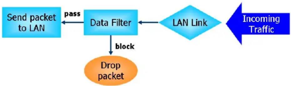
flowchart
graph TD
    A["Send packet to LAN"] -->|pass| B["Data Filter"]
    B -->|block| C["Drop packet"]
    C --> D["LAN Link"]
    D --> E["Incoming Traffic"]
Stateful Packet Inspection (SPI)
Stateful inspection is a firewall architecture that works at the network layer. Unlike legacy static packet filtering, which examines a packet based on the information in its header, stateful inspection builds up a state machine to track each connection traversing all interfaces of the firewall and makes sure they are valid. The stateful firewall of Vigor router not only examines the header information also monitors the state of the connection.
Denial of Service (DoS) Defense
DoS attacks are categorized into two types: flooding-type attacks and vulnerability attacks. Flooding-type attacks attempts to exhaust system resources while vulnerability attacks attempts to paralyze the system by exploiting vulnerabilities of protocols or operation systems.
Vigor's DoS Defense functionality detects DoS attacks and mitigates their damage by inspecting every incoming packet, and malicious packets will be blocked. If Syslog is enabled, alert messages will also be sent. Abnormal traffic flow such as flood and port scan attacks that exceed allowable thresholds are also blocked.
The below shows the attack types that DoS/ DDoS defense function can detect:
- SYN flood attack
- UDP flood attack
- ICMP flood attack
- Port Scan attack
- IP options
- Land attack
- Smurf attack
-
Trace route
-
SYN fragment
- Fraggle attack
- TCP flag scan
- Tear drop attack
- Ping of Death attack
- ICMP fragment
- Unassigned Numbers
Web User Interface
Below shows the menu items for Firewall.
Firewall
General Setup
Filter Setup
Defense Setup
Diagnose
IV-1-1 General Setup
General Setup Page
Such page allows you to enable / disable Call Filter and Data Filter, determine general rule for filtering the incoming and outgoing data.
Firewall >> General Setup
General Setup
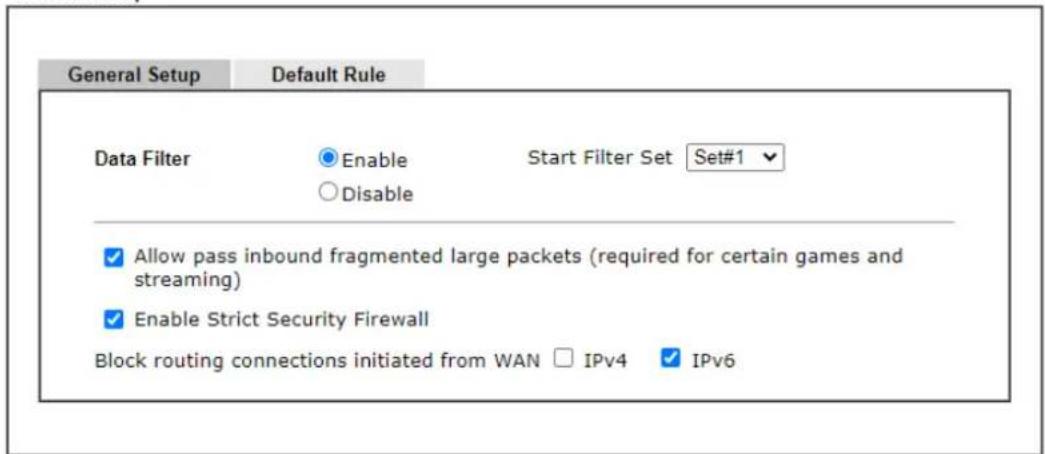
Note:
Packets are filtered by firewall functions in the following order:
- Data Filter Sets and Rules 2. Block routing connections initiated from WAN 3. Default Rule
OK Cancel
This will not backup the detail setting of Quality of Service and Schedule.
Available settings are explained as follows:
| Item | Description |
| Data Filter | Select Enable to activate the Data Filter function, and then choose a Start Filter Set. |
| Allow pass inbound fragmented large... | Certain games and video streaming service use fragmented UDP packets to transfer data. Enabling this option allows these applications to function properly.If this option is not enabled, the router will attempt to reassemble fragmented packets up to a certain value (e.g., 15xx~2102) kilobytes long. Packets larger than the certain value will be discarded.If this option is enabled, the router always passes fragmented packets without reassembling them, regardless of the size of the packet. |
| Enable Strict Security Firewall | If this option and the Web Content Filter (WCF) are both enabled, web traffic will be blocked if the WCF server fails to respond to lookup requests. |
| Block routing connections initiated from WAN | IPv6 - IPv6 does not make use of Network Address Translation (NAT), so all LAN hosts receive public IPv6 IP addresses that are exposed to the WAN. Enable this option to block WAN hosts from connecting to LAN hosts using IPv6.IPv4 - For LAN hosts receiving WAN IPv4 addresses using the IP routed subnet, enable this option to prevent WAN hosts from connecting to LAN hosts. This option has no effect on LAN hosts on private LAN subnets. |
| Backup Firewall | Click Backup to save the firewall configuration. |
| Restore Firewall | Click Select to choose a firewall configuration file. Then click Restore to apply the file. |
To save changes on the page, click OK. To discard changes, click Cancel.
Traffic is filtered by firewall functions in the following order:
- Data Filter Sets and Rules
- Block connections initiated from WAN
- Default Rule
Default Rule Page
This page allows you to choose filtering profiles including QoS, User Management, APP Enforcement, URL Content Filter, Web Content Filter and DNS Filter for data transmission via Vigor router.
The default rule applies to all traffic that is not constrained by other filters or rules.
Firewall >> General Setup
General Setup
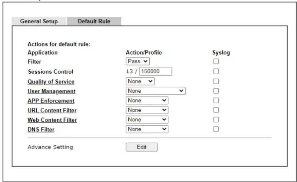

Note:
This will not backup the detail setting of Quality of Service and Schedule.
Available settings are explained as follows:
| Item | Description |
| Filter | Select Pass or Block for the packets that do not match with the filter rules. When the setting is Block, all other fields on the page are disabled because they are not applicable. |
| Sessions Control The current number of sessions is shown before the slash,followed by the maximum number of concurrent sessions allowed, which is configurable. The default maximum is 60000, which is also the upper limit of the value. | |
| Quality of Service Choose one of the QoS rules to be applied as firewall rule.For detailed information of setting QoS, please refer to the related section later. | |
| User Management | This setting is only available when Rule-Based is selected in User Management>>General Setup. The default firewall rule will be applied to the selected user or user group. Refer to the chapter on User Management for more details on the feature.● None- User Management does not apply to the defaultrule.User Object-The default rule only applies to the selected user.[Create New User]- Select this to create a new user.User Group: The default rule only applies to the selected User Group.[Create New Group]- Select this to create a new user group.ALL- The default rule applies to all defined users.Create New User or Create New Group item will appear for you to click to create a new one if there is no user profile or group profile existed.Syslog - Select to allow User Management to log messages in Syslog. |
| APP Enforcement Select an | APP Enforcement profile for application blocking, or None to disable APP Enforcement for the Default Rule.Select [Create New] from the dropdown list to create a new profile. Refer to the chapter on APP Enforcement for more details on the feature.Syslog - Select to allow APP Enforcement to log messages in Syslog. |
| URL Content Filter | Select a URL Content Filter profile to be used, or None to disable URL Content Filter for the Default Rule. Select [Create New] from the dropdown list to create a new profile. Refer to the chapter on URL Content Filter for more details on the feature.Syslog - Select to allow URL Content Filter to log messages in Syslog. Logging action is configured at the profile level in CSM>>URL Content Filter Profile, Log. |
| Web Content Filter Select a | Web Content Filter profile to be used, or None to disable Web Content Filter for the Default Rule. Select [Create New] from the dropdown list to create a new profile.Syslog - Select to allow Web Content Filter to log messages in Syslog. Logging action is configured at the profile level in the Web Content Filter Profile Table section in CSM>>Web Content Filter Profile, Log. |
| DNS Filter | Select the DNS Filter profile to be used, or None to disable DNS Filter for the Default Rule. Select [Create New] from the dropdown list to create a new profile.Syslog - Select to allow DNS Filter to log messages in Syslog. Logging action is configured at the profile level in the DNS Filter Profile Table section in CSM>>DNS Filter Profile, SysLog. |
| Advance Setting | Click Edit to open the configuration window for Advanced Settings. However, it is recommended to use the default settings. |
Firewall >> General Setup
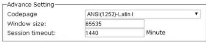

Codepage - Sets the codepage used by the URL content filter to match URLs against keywords in profiles. Choosing the appropriate codepage can increase the accuracy of the URL Content Filter. The default value is ANSI 1252 Latin I. If the setting is None, no decoding of URL will be performed.
If you are unsure of which codepage to use, please start the Syslog application, and the recommended codepage will be shown in the Codepage Information tab in the Setup dialog box.
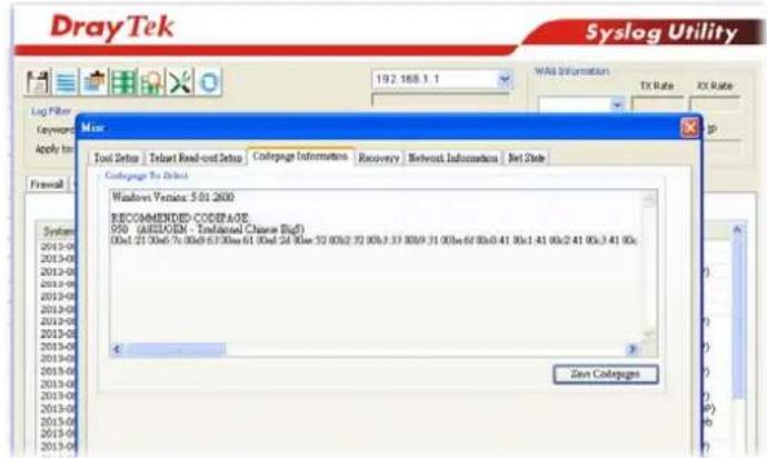
Window size - Sets the TCP window size as described in RFC 1323. Valid values are from 0 to 65535. The more the value is, the better the performance will be. However, if the network is not stable, small value will be proper.
Session timeout - Sets the timeout sessions are allowed to idle before they are removed from the system.
After finishing all the settings here, please click OK to save the configuration.
IV-1-2 Filter Setup
Click Firewall and click Filter Setup to bring up the setup page.
Firewall >> Filter Setup

| Set | Comments | Set | Comments |
| 1. | Default Call Filter | 26. | |
| 2. | Default Data Filter | 27. | |
| 3. | 28. | ||
| 4. | 29. | ||
| 5. | 30. | ||
| 6. | 31. | ||
| 7. | 32. | ||
| 8. | 33. | ||
| 9. | 34. | ||
| 10. | 35. | ||
| 11. | 36. | ||
| 12. | 37. | ||
| 13. | 38. | ||
| 14. | 39. | ||
| 15. | 40. | ||
| 16. | 41. | ||
| 17. | 42. | ||
| 18. | 43. | ||
| 19. | 44. | ||
| 20. | 45. | ||
| 21. | 46. | ||
| 22. | 47. | ||
| 23. | 48. | ||
| 24. | 49. | ||
| 25. | 50. |
To edit a filter set, click on its set number. The following Filter Set page will be shown. Each filter set contains up to 30 rules.
Firewall >> Filter Setup >> Edit Filter Set
Filter Set 1
Comments: Default Call Filter
| Rule | Enable | Comments | Direction | Src IP | Dst IP | Service Type | Action | CSM | Move Up | Move Down |
| 1 | Block NetBios | LAN/RT/VPN->WAN | Any | Any | TCP/UDP, Port: from 137~139 to any | Block Immediately | Down | |||
| 2 | LAN/RT/VPN->WAN | Any | Any | Any | Pass Immediately | UP | Down | |||
| 3 | LAN/RT/VPN->WAN | Any | Any | Any | Pass Immediately | UP | Down | |||
| 4 | LAN/RT/VPN->WAN | Any | Any | Any | Pass Immediately | UP | Down | |||
| 5 | LAN/RT/VPN->WAN | Any | Any | Any | Pass Immediately | UP | Down | |||
| 6 | LAN/RT/VPN->WAN | Any | Any | Any | Pass Immediately | UP | Down | |||
| 7 | LAN/RT/VPN->WAN | Any | Any | Any | Pass Immediately | UP | Down | |||
| 8 | LAN/RT/VPN->WAN | Any | Any | Any | Pass Immediately | UP | Down | |||
| 9 | LAN/RT/VPN->WAN | Any | Any | Any | Pass Immediately | UP | Down |
Available settings are explained as follows:
| Item | Description |
| Rule To edit the filter rule, | click the filter rule number (1 ~ 30) to bring up the Edit Filter Rule page. See the following section for details on the Edit Filter Rule page. |
| Enable Select to enable the | filter rule. |
| Comments | Optional comment entered in the settings page to identify the rule. |
| Direction Displays the direction of packet. | |
| Src IP / Dst IP Displays the IP address of source / destination. | |
| Service Type Displays the type and port number of the packet. | |
| Action Displays the packets to be passed / blocked. | |
| CSM Displays the content security managed | |
| Move Up/Down | Use Up or Down link to change the order of the filter rules. |
| Next Filter Set | Select the filter set for the firewall to process after the current filter set, or None if the current filter set is the last one to be processed. Be careful not to create a loop when setting next filter sets. |
| Wizard Mode | Allow to configure frequently used settings for filter rule via several setting pages. |
| Advance Mode | Allow to configure detailed settings of filter rule. |
To use Wizard Mode, simple do the following steps:
- Click the Wizard Mode radio button.
- Click Index 1. The setting page will appear as follows:
Firewall >> Edit Filter Set >> Edit Filter Rule Wizard
Filter Set 1 Rule 1
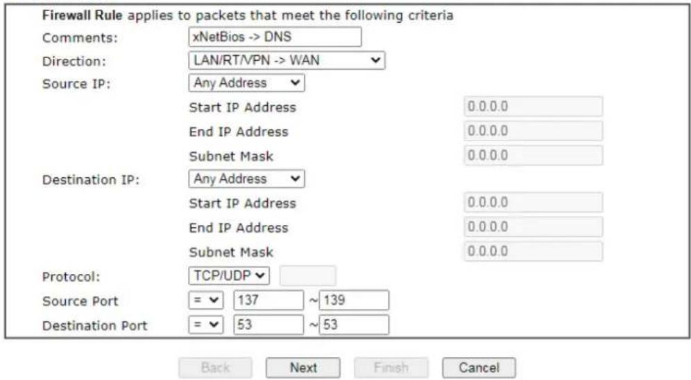
Available settings are explained as follows:
| Item | Description |
| Comments | Enter filter set comments/ description. Maximum length is 14- character long. |
| Direction Set the direction of packet flow. | |
| LAN/RT/VPN -> WAN ▼LAN/RT/VPN -> WANWAN -> LAN/RT/VPNLAN/RT/VPN -> LAN/RT/VPNNote: RT means routing domain for 2nd subnet or other LAN. | |
| Source/Destination IP | To set the IP address manually, please choose Any Address/Single Address/Range Address/Subnet Address as the Address Type and type them in this dialog. |
| Protocol | Specify the protocol(s) which this filter rule will apply to. |
| Source Port / Destination Port | (=) - when the first and last value are the same, it indicates one port; when the first and last values are different, it indicates a range for the port and available for this service type.(!=) - when the first and last value are the same, it indicates all the ports except the port defined here; when the first and last values are different, it indicates that all the ports except the range defined here are available for this service type.(>) - the port number greater than this value is available.(<) - the port number less than this value is available for this profile. |
- Click Next to get the following page.
Firewall >> Edit Filter Set >> Edit Filter Rule Wizard
Filter Set 1 Rule 1
| Based on the settings in the previous pages, we guess you want to have: PassThe current setting is:● Pass Immediately○ Block Immediately |

Available settings are explained as follows:
| Item | Description |
| Pass Immediately Packets matching the rule will be passed immediately. | |
| Block Immediately Packets matching the rule will be dropped immediately. | |
- After choosing the mechanism, click Next to get the summary page for reference.
Filter Set 1 Rule 1 Configuration Summary
| Comments : | Block NetBios | |
| Direction | ||
| LAN/RT/VPN -> WAN | ||
| Criteria | ||
| Source IP | Any | |
| Destination IP | Any | |
| Protocol | TCP/UDP, Port: from 137 ~ 139 to any | |
| More options | ||
| Pass Immediately | ||
| APP Enforcement : None | ||
| URL Content Filter : None | ||
| Web Content Filter : 1 - Default | ||
| DNS Filter : None | ||

- If there is no error, click Finish to complete wizard setting.
To use Advance Mode, do the following steps:
- Click the Advance Mode radio button.
- Click Index 1 to access into the following page.
Firewall >> Edit Filter Set >> Edit Filter Rule
Filter Set 1 Rule 1
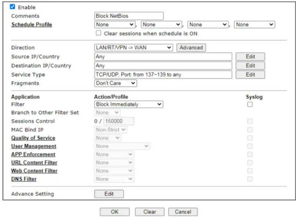
Available settings are explained as follows:
| Item | Description |
| Enable Check this box to enable the filter rule. | |
| Comments | Enter filter set comments/ description. Maximum length is 14- character long. |
| Schedule Profile Select | Schedule indexes to allow the rule to be enabled at specific times. You may choose up to 4 out of the 15 schedules in Applications >> Schedule. The rule is always enabled when no indexes have been selected. |
| Clear sessions when schedule is ON | Select this option to clear existing sessions when the rule is changes is enabled by a schedule profile. All connections will be reset. |
| Direction Specify the direction of traffic flow to which this filter rule applies. Note that when the rule belongs to the Call Filter, the WAN -> LAN/ RT/ VPN option has no effect as Call Filter applies only to outgoing traffic.LAN/RT/VPN -> WANLAN/RT/VPN -> WANWAN -> LAN/RT/PNLAN/RT/VPN -> LAN/RT/VPNEnd ID Address | |
Note: RT stands for the routing domain for 2nd subnet or other LAN.Advanced - After choosing the direction, click the Advanced button to specify interfaces for traffic flow.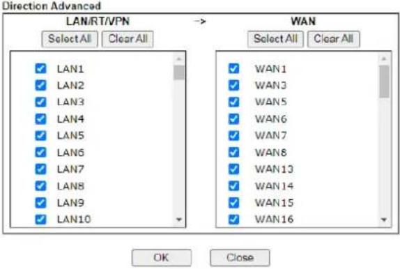 | |
| Source IP/ Country and Destination IP / Country | Click Edit to bring up the following dialog box to configure the source and destination IP addresses or country objects.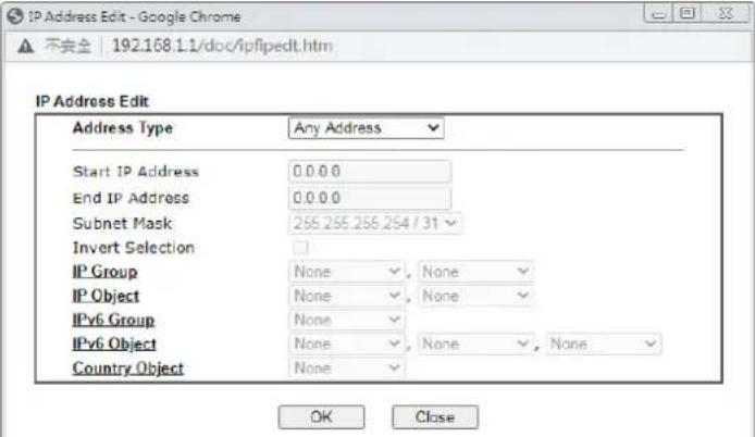 To set the IP address manually, please choose an Address Type and enter required information.Address Type - Select from one of the following:Any Address - All IP addressesSingle Address - Enter one IP address in Start IP addressRange Address - Enter the Start and End IP AddressesSubnet Address - Enter the Start IP Address and the Subnet Mask. Example: Start IP Address 192.168.1.1 and Subnet Mask 255.255.255.128 means is the same as having the Start IP Address as 192.168.1.1 and the End IP Address as 192.168.1.127.Group and Objects - Allows selection of predefined IP Groups and IP Objects. For details on IP Groups and Objects, see the chapter on Objects Setting.Country Object - Allows selection of predefined country objects. To set the IP address manually, please choose an Address Type and enter required information.Address Type - Select from one of the following:Any Address - All IP addressesSingle Address - Enter one IP address in Start IP addressRange Address - Enter the Start and End IP AddressesSubnet Address - Enter the Start IP Address and the Subnet Mask. Example: Start IP Address 192.168.1.1 and Subnet Mask 255.255.255.128 means is the same as having the Start IP Address as 192.168.1.1 and the End IP Address as 192.168.1.127.Group and Objects - Allows selection of predefined IP Groups and IP Objects. For details on IP Groups and Objects, see the chapter on Objects Setting.Country Object - Allows selection of predefined country objects. |
| Service Type | Click Edit to bring up the following dialog box to configure the Service Type.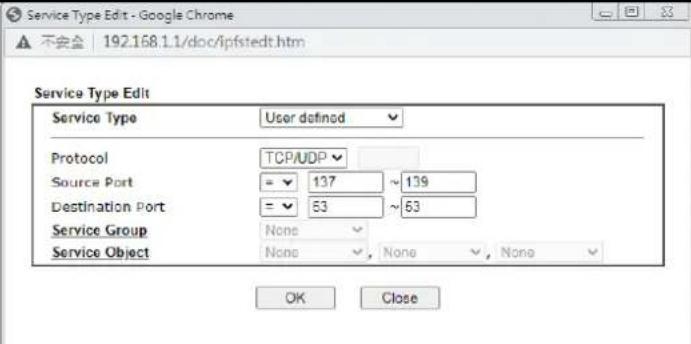 Service Type- To set the service type manually, please choose User defined as the Service Type.User defined- Configure the protocol, source and destination ports manually.Group and Objects- Select preconfigured Service Groups or Objects.Protocol - Specify the protocol(s) which this filter rule will apply to.Source/Destination Port -(=)- any port that falls within the specified range(!=)- any port that falls outside of the specified range(>) - a port whose number is greater than the specified value(<)- a port whose number is smaller than the specified valueService Group/Object- Use the drop down list to select the desired Service Groups or Objects. Service Type- To set the service type manually, please choose User defined as the Service Type.User defined- Configure the protocol, source and destination ports manually.Group and Objects- Select preconfigured Service Groups or Objects.Protocol - Specify the protocol(s) which this filter rule will apply to.Source/Destination Port -(=)- any port that falls within the specified range(!=)- any port that falls outside of the specified range(>) - a port whose number is greater than the specified value(<)- a port whose number is smaller than the specified valueService Group/Object- Use the drop down list to select the desired Service Groups or Objects. |
| Fragments Action to be taken for fragmented packets. This option is valid for Data Filter rules only.Don't care-No action will be taken towards fragmented packets.Unfragmented -Apply the rule to unfragmented packets.Fragmented - Apply the rule to fragmented packets.Too Short - Apply the rule only to packets that are too short to contain a complete header. | |
| Filter Action to be taken when packets match the rule.Block Immediately-Packets matching the rule will be dropped immediately.Pass Immediately-Packets matching the rule will be passed immediately.Block If No Further Match- Block the packet if this the last matching rule for this packet in the filter.Pass If No Further Match- Pass the packet if this is the last matching rule for this packet in the filter. | |
| Branch to other Filter Set | If the packet matches the filter rule, and the Filter action is Block If No Further Match or Pass If No Further Match, you can specify the next filter set to be applied, thus skipping the rest of the rules in the current filter set. |
| Sessions Control The current number of sessions is shown before the slash,followed by the maximum number of concurrent sessions allowed, which is configurable. The default maximum is | |
| 60000, which is also the upper limit of the value. | |
| MAC Bind IP Strict – Ensure that both the MAC address and the IP address of the source and/or destination clients.Non-Strict – Do not check the IP address when processing IP Objects that specify MAC addresses. | |
| Quality of Service Choose one of the QoS rules to be applied as firewall rule.For detailed information of setting QoS, please refer to the related section later. | |
| User Management | This setting is only available when Rule-Based is selected in User Management>>General Setup. The default firewall rule will be applied to the selected user or user group.Refer to the chapter on User Management for more details on the feature.None-User Management does not apply to the default rule.User Object- The default rule only applies to the selected user.[Create New User]- Select this to create a new user.User Group: The default rule only applies to the selected User Group.[Create New Group]- Select this to create a new user group.ALL-The default rule applies to all defined users.Create New User or Create New Group item will appear for you to click to create a new one if there is no user profile or group profile existed.Syslog - Select to allow User Management to log messages in Syslog. |
| APP Enforcement Select an APP Enforcement profile for application blocking, or None to disable APP Enforcement for the Default Rule.Select [Create New] from the dropdown list to create a new profile. Refer to the chapter on APP Enforcement for more details on the feature.Syslog - Select to allow APP Enforcement to log messages in Syslog. | |
| URL Content Filter | Select a URL Content Filter profile to be used, or None to disable URL Content Filter for the Default Rule. Select [Create New] from the dropdown list to create a new profile. Refer to the chapter on URL Content Filter for more details on the feature.Syslog - Select to allow URL Content Filter to log messages in Syslog. Logging action is configured at the profile level in CSM>>URL Content Filter Profile, Log. |
| Web Content Filter Select a Web Content Filter profile to be used, or None to disable Web Content Filter for the Default Rule. Select [Create New] from the dropdown list to create a new profile.Syslog - Select to allow Web Content Filter to log messages in Syslog. Logging action is configured at the profile level in the Web Content Filter Profile Table section in CSM>>Web Content Filter Profile, Log. | |
| DNS Filter | Select the DNS Filter profile to be used, or None to disable DNS Filter for the Default Rule. Select [Create New] fromthe dropdown list to create a new profile.Syslog - Select to allow DNS Filter to log messages in Syslog. Logging action is configured at the profile level in the DNS Filter Profile Table section in CSM>>DNS Filter Profile, SysLog. |
| Advance Setting | Click Edit to open the configuration window for Advanced Settings. However, it is recommended to use the default settings.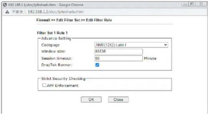 Codepage - Sets the codepage used by the URL content filter to match URLs against keywords in profiles. Choosing the appropriate codepage can increase the accuracy of the URL Content Filter. The default value is ANSI 1252 Latin I. If the setting is None, no decoding of URL will be performed. If you are unsure of which codepage to use, please start the Syslog application, and the recommended codepage will be shown in the Codepage Information tab in the Setup dialog box. Codepage - Sets the codepage used by the URL content filter to match URLs against keywords in profiles. Choosing the appropriate codepage can increase the accuracy of the URL Content Filter. The default value is ANSI 1252 Latin I. If the setting is None, no decoding of URL will be performed. If you are unsure of which codepage to use, please start the Syslog application, and the recommended codepage will be shown in the Codepage Information tab in the Setup dialog box.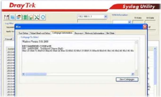 Window size - Sets the TCP window size as described in RFC 1323. Valid values are from 0 to 65535. The more the value is, the better the performance will be. However, if the network is not stable, small value will be proper.Session timeout - Sets the timeout sessions are allowed to idle before they are removed from the system.DrayTek Banner - Select to display the following screen for web pages that are blocked by the Firewall. The default setting is Enabled. Window size - Sets the TCP window size as described in RFC 1323. Valid values are from 0 to 65535. The more the value is, the better the performance will be. However, if the network is not stable, small value will be proper.Session timeout - Sets the timeout sessions are allowed to idle before they are removed from the system.DrayTek Banner - Select to display the following screen for web pages that are blocked by the Firewall. The default setting is Enabled. |
The requested Web page has been blocked by Web Content Filter.
Please contact your system administrator for further information.
[Powered by Draytek]
Strict Security Checking
APP Enforcement - If this option is selected, when the router cannot identify the application that generated the outbound traffic due to limited system resources, the session will be blocked; if this option is not selected, the session will be allowed.
- When you finish the configuration, please click OK to save and exit this page.
IV-1-3 Defense Setup
As a sub-functionality of IP Filter/ Firewall, there are 15 types of detect/ defense function in the DoS Defense setup. The DoS Defense functionality is disabled for default.
IV-1-3 -1 DoS Defense
To configure DoS Defense, select DoS Defense under the Firewall menu item on the Web UI menu bar.
Firewall >> Defense Setup
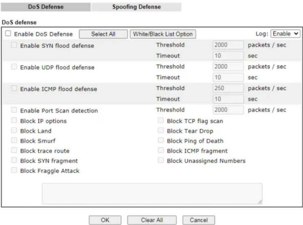
Available settings are explained as follows:
| Item | Description |
| Enable Dos Defense Select | to enable DoS Defense.Select All - Click to select all DoS Defense options.White/Black List Option - Set white/ black list of IPv4/ IPv6 address. |
| Enable SYN flood defense | Select to enable SYN flood defense. When the arrival rate of SYN packets exceeds the Threshold value, the router will start to randomly discard TCP SYN packets for a period of time as defined in Timeout. This is to prevent TCP SYN packets from exhausting router resources.The default values of threshold and timeout are 2000 packets per second and 10 seconds, respectively. |
| Enable UDP flood defense | Select to enable UDP flood defense. When the arrival rate of UDP packets exceeds the Threshold value, the router will start to randomly discard TCP SYN packets for a period of time as defined in Timeout.The default values of threshold and timeout are 2000packets per second and 10 seconds, respectively. |
| Enable ICMP flood defense | Select to enable ICMP flood defense. When the arrival rate of ICMP packets exceeds the Threshold value, the router will start to randomly discard TCP SYN packets for a period of time as defined in Timeout.The default values of threshold and timeout are 250 packets per second and 10 seconds, respectively. |
| Enable PortScan detection | Select to enable Port Scan detection. Port Scans attack your network by sending packets to a range of ports in an attempt to find services that would respond. When Port Scan detection is enabled, the router sends warning messages when it detects port scanning activities that exceed the Threshold rate.The default threshold is 2000 packets per second. |
| Block IP options Select to en | able Block IP options. The Vigor router will ignore IP packets with IP option field set in the datagram header. IP options are rarely used and could be abused by attackers as they carry information about the private network otherwise not available to the external network, such as security, TCC (closed user group) parameters, a series of Internet addresses, routing messages, etc, which external eavesdroppers can use to discover details about the private network. |
| Block Land Select to Block | LAND attacks. LAND attacks happen when an attacker sends spoofed SYN packets with both source and destination addresses set to that of the target system, which causes the target to reply to itself continuously. |
| Block Smurf | Select to Block Smurf attacks. The router will ignore any broadcasting ICMP echo request. |
| Block trace route | Select to Block traceroutes. The router will not forward traceroute packets. |
| Block SYN fragment Select | to Block SYN packet fragments. The router will drop any packets having both the SYN and more-fragments bits set. |
| Block Fraggle Attack Select | to Block Fraggle Attacks. Broadcast UDP packets received from the Internet are blocked.Activating this feature might block some legitimate packets. Since all broadcast UDP packets coming from the Internet are blocked, RIP packets from the Internet could also be dropped. |
| Block TCP flag scan | Select to Block TCP Flag Scans. TCP packets with abnormal flag settings will be dropped. TCP flag scanning activities that are blocked include no flag scan, FIN without ACK scan, SYN FIN scan, Xmas scan and full Xmas scan. |
| Block Tear Drop Select to B | Block Tear Drop attacks. Some clients may crash when they receive ICMP datagrams (packets) that exceed the maximum length. The router discards any fragmented ICMP packets having lengths greater than 1024 octets. |
| Block Ping of Death Select | to Block Ping of Death, where fragmented ping packets are sent to target hosts so that those hosts could crash as they reassemble the malformed ping packets. |
| Block ICMP Fragment | Select to Block ICMP Fragments. ICMP packets with the more-fragments bit set are dropped. |
| Block Unassigned Numbers | Select to Block Unassigned Protocol Numbers, and the router will block packets having unassigned protocol numbers. Individual IP packet has a protocol field in the datagram header to indicate the protocol type running over the upper layer. However, the protocol types greater than 100 are reserved and undefined at this time. Therefore, the router should have ability to detect and reject this kind of packets. |
Warning Messages We provide Syslog function for user to retrieve message from Vigor router. The user, as a Syslog Server, shall receive the report sending from Vigor router which is a Syslog Client.All the warning messages related to DoS Defense will be sent to user and user can review it through Syslog daemon. Look for the keyword DoS in the message, followed by a name to indicate what kind of attacks is detected.System Maintenance >> SysLog / Mail Alert Setup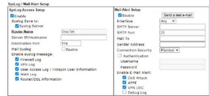 Note:1. Mail Syslog feature will send the Syslog when it is full.OKClear Note:1. Mail Syslog feature will send the Syslog when it is full.OKClear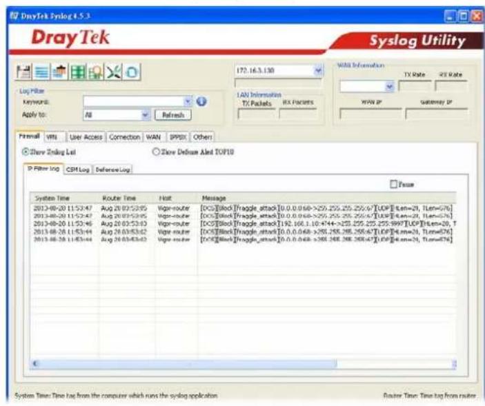 | |
After finishing all the settings here, please click OK to save the configuration.
IV-1-3-2 Spoofing Defense
Click the Spoofing Defense tab to open the setup page.
Firewall >> Defense Setup
DoS Defense
Spoofing Defense
ARP Spoofing Defense
Log: Enable ▼
√ Block ARP replies with inconsistent source MAC addresses.
√ Block ARP replies with inconsistent destination MAC addresses.
√ Decline VRRP MAC into ARP table.
IP Spoofing Defense
√ Block IP packet from WAN with inconsistent source IP addresses.
☐ Block IP packet from LAN with inconsistent source IP addresses.
OK
Cancel
IV-1-4 Diagnose
The purpose of this function is to test when the router receiving incoming packet, which firewall rule will be applied to that packet. The test result, including firewall rule profile, IP address translation in packet transmission, state of the firewall functions and etc., also will be shown on this page.

Info
The result obtained by using Diagnose is offered for RD debug. It will be different according to actual state such as network connection, LAN/WAN settings and so on.
Firewall >> Diagnose
Mode

Direction

Test View
A


LAN

Firewall

B

Src IP
Src Port
Src MAC
Packet & Payload
| Packet | Enable | Direction | Protocol |
| 1 | A->B▼ | UDP:Customize | |
| 2 | A->B▼ | UDP:Customize |
Note:
This is firewall live test which need setup WAN and plug cable in.
Analyze
Available settings are explained as follows:
| Item | Description |
| Mode To have a firewall rule test, specify the service type (ICMP, | |
| UDP, TCP) of the packet and type of the IP address (IPv4/ IPv6). | |
| Direction Set the way (from | WAN or from LAN) that Vigor router receives the first packet for test. Different way means the firewall will process the connection initiated from LAN or from WAN. |
| Test View This is a dynamic display page. According to the direction specified, test view will display the figure to guide you typing IP address, port number, and MAC address.Later, after clicking the Analyze button, the information for the firewall rule profile and address translation will be shown on this page. | |
| Src IP Enter the IPv4/ IPv6 address of the packet's source. | |
| Src Port Enter the port number of the packet's source. | |
| Src MAC Enter the MAC address of the packet's source. | |
| Dst IP Enter the IPv4/ IPv6 address of the packet's destination. | |
| Dst Port Enter the port number of the packet's destination. | |
Packet & Payload In firewall diagnose, two packets belong to one connection.In general, two packets are enough for Vigor router to perform this test.Enable - Check the box to send out the test packet.Direction - The first packet of the firewall test will follow the direction specified above. However, the direction for the second packet might be different. Simply choose the direction (from Computer A to B or from the B to A) for the second packet.Protocol - It displays the mode selected above and the sate. If required, click the mode link to configure advanced setting. The common service type (Customize, Ping, Trace Route / Customize, DNS, Trace Route / Customize, Http(GET) related to that mode (ICMP / UDP / TCP) will be shown on the following dialog box.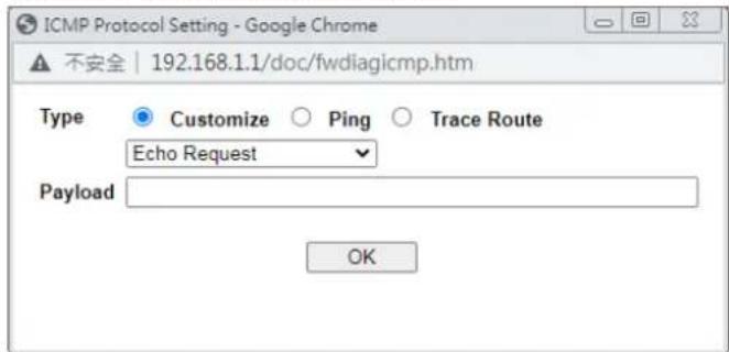 Type - Choose Customize, Ping, Trace Route / Customize, DNS, Trace Route / Customize, Http (GET).Payload - It is available when Customzie is selected. Simply type 16 HEX characters which represent certain packet (e.g., DNS packet) if you want to set the data transferred with protocol (ICMP/UDP/TCP) which is different to Type setting. Type - Choose Customize, Ping, Trace Route / Customize, DNS, Trace Route / Customize, Http (GET).Payload - It is available when Customzie is selected. Simply type 16 HEX characters which represent certain packet (e.g., DNS packet) if you want to set the data transferred with protocol (ICMP/UDP/TCP) which is different to Type setting. | |
| Analyze Execute the test and analyze the result. | |
The following figure shows the test result after clicking Analyze. Processing state for the fuctions (MAC Filter, QoS, User management, etc.,) related to the firewall will be displayed by green or red LED.
Firewall >> Diagnose
Mode

Direction

Test View
A

192.168.1.111:22222
7.7.7.7:51348

LAN
ORIGIN»

WAN1

Firewall
7.7.7.7:51348 172.16.2.234:62094-

| Status | Packet | Set | Rule | UCF/WCF |
| Pass | 2 | default | default | n/a |
Packet & Payload

APP: The APP need to check.
APP:The APP doesn't need to check.
The APP is completed.
The APP is processing.
Note:
PCAP is "ip pcap" in telnet command.
<<Back Reset
Application Notes
A-1 How to Configure Certain Computers Accessing to Internet
We can specify certain computers (e.g., 192.168.1.10 \~ 192.168.1.20) accessing to Internet through Vigor router. Others (e.g., 192.168.1.31 and 192.168.1.32) outside the range can get the source from LAN only.
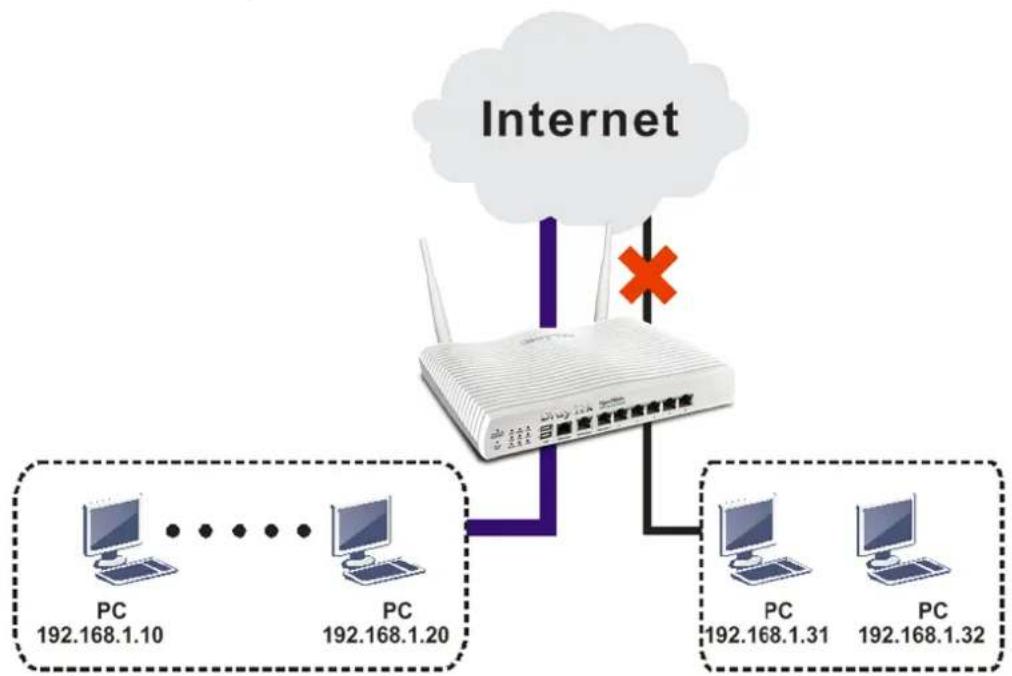
flowchart
graph TD
    A["Router"] --> B["PC 192.168.1.10"]
    A --> C["PC 192.168.1.20"]
    A --> D["PC 192.168.1.31"]
    A --> E["PC 192.168.1.32"]
    F["Internet"] --> G["Wireless Cloud"]
    G --> H["Red X Marker"]
    style G fill:#f9f,stroke:#333,stroke-width:2px
The way we can use is to set two rules under Firewall. For Rule 1 of Set 2 under Firewall>>Filter Setup is used as the default setting, we have to create a new rule starting from Filter Rule 2 of Set 2.
-
Access into the web user interface of Vigor router.
-
Open Firewall>>Filter Setup. Click the Set 2 link and choose the Filter Rule 2 button.
Firewall >> Filter Setup
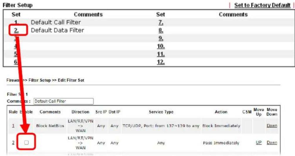
- Check Enable to enable the filter rule. Type the comments (e.g., block_all). Choose Block If No Further Match for the Filter setting. Then, click OK.
Firewall >> Edit Filter Set >> Edit Filter Rule
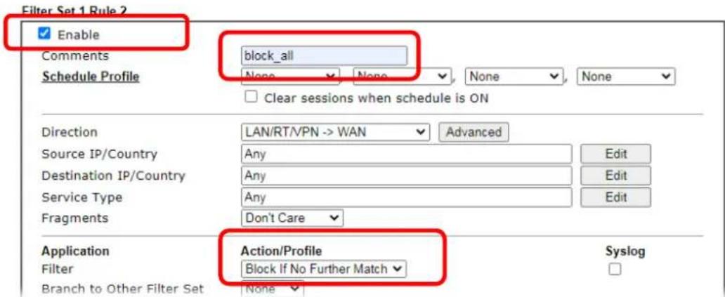

Info
In default, the router will check the packets starting with Set 2, Filter Rule 2 to Filter Rule 7. If Block If No Further Match for is selected for Filter, the firewall of the router would check the packets with the rules starting from Rule 3 to Rule 7. The packets not matching with the rules will be processed according to Rule 2.
- Next, set another rule. Just open Firewall>>Filter Setup. Click the Set 2 link and choose the Filter Rule 3 button.
- Check Enable to enable the filter rule. Type the comments (e.g., open_ip). Click the Edit button for Source IP.
Firewall >> Edit Filter Set >> Edit Filter Rule
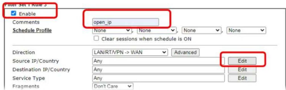
- A dialog box will be popped up. Choose Range Address as Address Type by using the drop down list. Type 192.168.1.10 in the field of Start IP, and type 192.168.1.20 in the field of End IP. Then, click OK to save the settings. The computers within the range can access into the Internet.
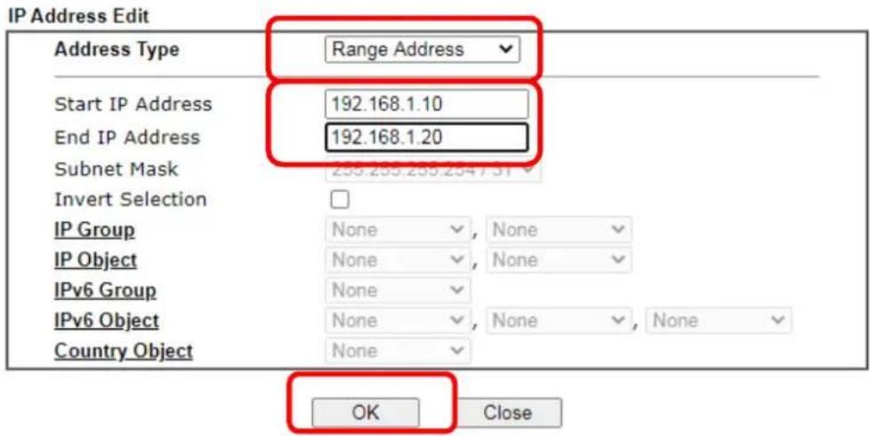
- Now, check the content of Source IP is correct or not. The action for Filter shall be set with Pass Immediately. Then, click OK to save the settings.
Firewall >> Edit Filter Set >> Edit Filter Rule
Filter Set 1 Rule 3
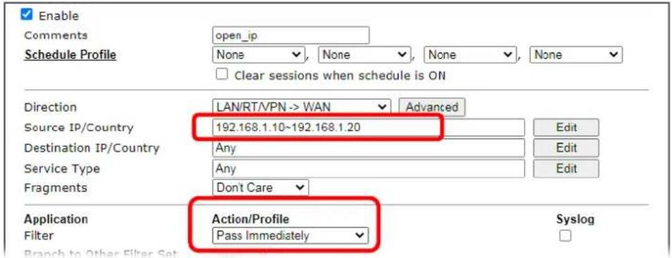
- Both filter rules have been created. Click OK.
Firewall >> Filter Setup >> Edit Filter Set
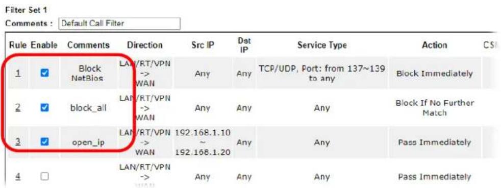
Now, all the settings are configured well. Only the computers with the IP addresses within 192.168.1.10 \~ 192.168.1.20 can access to Internet.
IV-2 CSM (Central Security Management)
Content Security Management (CSM) allows the network administrator to restrict Internet traffic based on the content type, thus ensuring appropriate use of network resources and also reducing the likelihood of threats from malicious network content.
APP Enforcement Filter
The APP Enforcement Filter can be used to prevent users from using undesirable or inappropriate network applications such as online chat and peer-to-peer programs. The filter works by detecting and blocking network traffic of applications by means of traffic patterns.
URL Content Filter
The URL Content Filter scans URL strings in HTTP requests for predefined keywords to restrict browsing activities.
Web Content Filter
Users can also be prevented from browsing certain types of websites by using the Web Content Filter. This filter classifies website domain names into different categories, which can be selectively blocked.
Filter profiles must first be created before these CSM Filters can be enabled. Once profiles have been configured, they can be applied to the Default Rule under Firewall>>General Setup, or Filter Rules in Filter Sets under Firewall>>Filter Setup.

Info
The priority of URL Content Filter is higher than Web Content Filter.
Web User Interface
CSM
APP Enforcement Profile
URL Content Filter Profile
Web Content Filter Profile
DNS Filter Profile
Bandwidth Management
IV-2-1 APP Enforcement Profile
Up to 32 policy profiles for APP Enforcement can be configured.
CSM >> APP Enforcement Profile

APPE Module Version: 15.29 APPE Support List
APP Enforcement Profile Table:
Set to Factory Default
Note:
To make APP Enforcement profile effective, please go to Firewall >> Filter Setup page to create a firewall rule and select the desired profile.
Available settings are explained as follows:
| Item | Description |
| Set to Factory Default Clear | all profile settings. |
| Profile Index of the profile. | Click to bring up the configuration page of the profile. |
| Name Name of the profile. |
To configure a profile, click on its profile number, and the following profile configuration page will appear:
CSM >> APP Enforcement Profile
Profile Index : 1
Profile Name:
Clone Profile
| Category Instant Message Select All Clear All | Application | ||
| AIM Login | AliWW | Ares | |
| BaiduHi | Facebook/Instagram | Fetion | |
| GaduGadu Protocol | ICQ | iSpQ | |
| KC | LINE | ||
| Paltalk | PocoCall | Qnext | |
| Signal | Slack | Snapchat | |
| Telegram | Tencent QQ | UC | |
| WebIM URLs | |||
| VoIP | |||
| Select All Clear All | RC Voice | Skype | TeamSpeak |
| TelTel | |||
Available settings are explained as follows:
| Item | Description |
| Profile Name Name that identifies this profile. Maximum length is 15 characters. | |
| Category | Apps are classified into several categories. Each category contains several apps to be blocked. |
| Select All Click to select all of the items on this page. | |
| Clear All Click to deselect all selected items. | |
| Enable Select this checkbox to block the app. | |
To save changes on the page, click OK. To discard changes, click Cancel.
IV-2-2 URL Content Filter Profile
To set up URL Content Filter Profiles, click CSM on the Main Menu bar, and then click URL Content Filter Profile to open the profile setting page.
CSM >> URL Content Filter Profile

URL Content Filter Profile Table:
Set to Factory Default
| Profile | Name | Profile | Name |
| 1. | 5. | ||
| 2. | 6. | ||
| 3. | 7. | ||
| 4. | 8. |
Note:
To make URL Content Filter profile effective, please go to Firewall >> Filter Setup page to create a firewall rule and select the desired profile.
Administration Message (Max 255 characters)
Default Message
The requested Web page has been blocked by URL Content Filter.
Please contact your system administrator for further information.
OK
Each item is explained as follows:
| Item | Description |
| Set to Factory Default Clear all profile settings. | |
| Profile Index number of the profile. | |
| Name Name that identifies the profile. | |
| Administration Message The message to be displayed in the browser when access to a URL has been blocked. A custom message can be entered with HTML formatting in the text box.Default Message - Click to reset the administration message to the factory default. | |
To set up a profile, click the profile number under Index column to bring up the configuration page.
Profile Index: 1
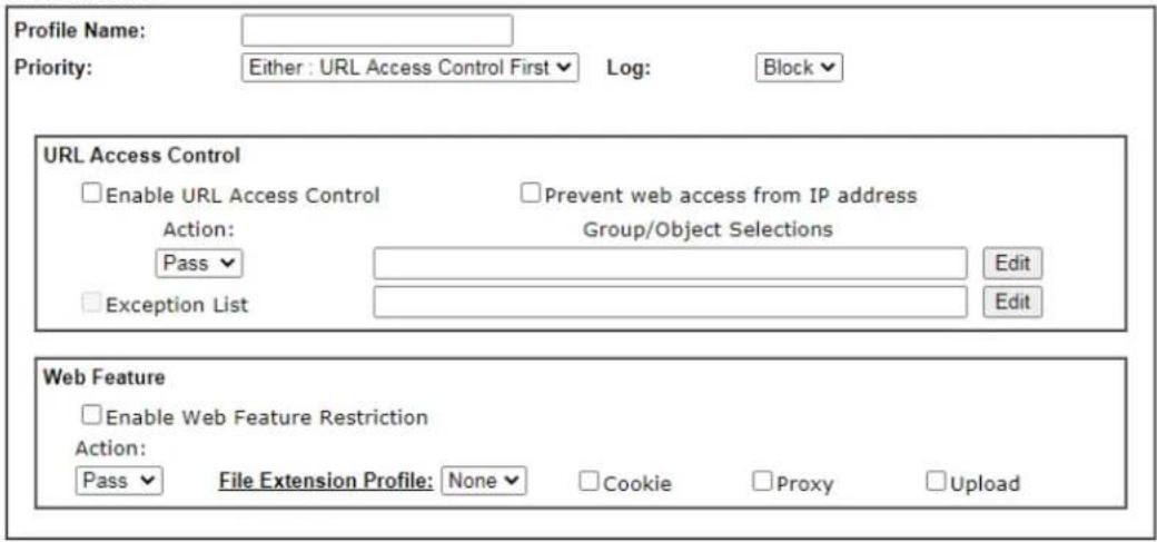

Available settings are explained as follows:
| Item | Description |
| Profile Name | Name that identifies the URL Content Filter profile. The maximum length of the Profile Name is 15 characters. |
| Priority The order of evaluation of URL Access Control and Web Feature below:Both: Pass - Router will allow access only to web resources that match conditions specified in both URL Access Control and Web Feature. The Action setting of both URL Access Control and Web Feature will be disabled and the values set to Pass.Both:Block - Router will block access to web resources that match conditions specified in both URL Access Control and Web Feature. The Action setting of both URL Access Control and Web Feature will be disabled and the values set to Block.Either: URL Access Control First - Router will block or allow access to web resources that match conditions specified in either URL Access Control or Web Feature. URL Access Control is applied first, followed by Web Feature.Either: Web Feature First - Router will block or allow access to web resources that match conditions specified in either URL Access Control or Web Feature. Web Feature is applied first, followed by URL Access Control. | |
| Log | Pass - Only passed access attempts will be recorded in Syslog.Block - Only blocked access attempts will be recorded in Syslog.All - Both passed and blocked access attempts will be recorded in Syslog. |
| URL Access Control Enable | URL Access Control - Select to activate URL Access Control.Prevent web access from IP address - URLs containing IP addresses (e.g., 192.168.1.1) will be blocked. Only URLs with domain addresses (e.g., www.draytek.com) will be allowed.This is to prevent users from circumventing URL Access Control.Action- This setting is enabled only when Priority is set to Either: URL Access Control First or Either: Web Feature First.Pass- Allows access to web pages with URLs containing keywords that are in the selected keyword groups or objects. Access to other URLs is blocked.Block- Blocks access to web pages with URLs containing keywords that are in the selected keyword groups or objects. Access to other URLs is allowed.Exception List- Specify the object profile(s) as the exception list which will be processed in an opposite manner to the action selected above.Group/Object Selections- Shows the Keyword Groups and/ or Objects selected for this URL Content Filter Profile. To add or remove Keyword Groups and Objects to the selection, click theEditbutton to bring up the following screen.Object/Group EditKeyword ObjectNone✓or Keyword ObjectNone✓or Keyword ObjectNone✓or Keyword ObjectNone✓or Keyword ObjectNone✓or Keyword ObjectNone✓or Keyword ObjectNone✓or Keyword GroupNone✓or Keyword GroupNone✓or Keyword GroupNone✓or Keyword GroupNone✓or Keyword GroupNone✓or Keyword GroupNone✓or Keyword GroupNone✓or Keyword GroupNone✓or Keyword GroupNone✓or Keyword GroupNone✓or Keyword GroupNone✓or Keyword GroupNone✓or Keyword GroupNone✓or Keyword GroupNone✓or Keyword GroupNone✓or Keyword GroupNone✓or Keyword GroupNone✓or Keyword GroupNone✓or Keyword GroupNone✓or Keyword GroupNone✓or Keyword group |
| OKCloseUp to 8 Keyword Objects and 8 Keyword Groups can be selected. To add, remove or modify Groups or Objects, click the Keyword Object or Keyword Group hyperlinks to bring up theObjects Setting >> Keyword Object or Objects Setting >> Keyword Group pages. | |
| Web Feature Enable Restrict Web Feature - Check to enable the web feature restriction.Action- This setting is enabled only when Priority is set to Either: URL Access Control First or Either: Web Feature First.Pass- Allows access to web pages with URLs containing keywords that are in the selected keyword groups or objects. Access to other URLs is blocked.Block- Blocks access to web pages with URLs containing keywords that are in the selected keyword groups or objects. Access to other URLs is allowed.File Extension Profile- Choose one of the profiles that you configured inObject Setting>>File Extension Objects previously for passing or blocking the file downloading. | Cookie - Select to block cookies from Internet websites.Proxy - Select to block web proxy servers that relay HTTP traffic.Upload - Select to block HTTP uploads from the LAN to the Internet. |
To save changes on the page, click OK. To discard changes, click Cancel. To clear all settings, click Clear.
IV-2-3 Web Content Filter Profile
Trial WCF service can be activated using the Service Activation Wizard.
If you wish to continue using WCF beyond the trial period, you can obtain a full WCF subscription by contacting your local DrayTek channel partner or dealer. WCF subscriptions can be activated using the Activate link on CSM >> Web Content Filter Profile (described in this section) or System Maintenance.
From the main menu, click CSM, followed by Web Content Filter Profile to load the profile configuration page.

Info 1
Web Content Filter (WCF) is not a built-in service of Vigor router but a service powered by Commtouch. If you want to use such service (trial or formal edition), you have to perform the procedure of activation first. For the service of formal edition, please contact with your dealer/distributor for detailed information.
Info 2 Commtouch is merged by Cyren, and GlobalView services will be continued to deliver powerful cloud-based information security solutions! Refer to: http://www.prnewswire.com/news-releases/commtouch-is-now-cyren-239025151.html
CSM >> Web Content Filter Profile

Web-Filter License
Activate
[Status: Activated] [Provider:'URL Reputation'] [Start Date:2023-07-21 Expire Date:'2023-08-20']
| Setup Query Server | auto-selected | Find more |
| Setup Test Server | auto-selected | Find more |
Web Content Filter Profile Table:
Cache : L1 + L2 Cache ▼ | Set to Factory Default
| Profile | Name | Profile | Name |
| 1. | Default | 5. | |
| 2. | 6. | ||
| 3. | 7. | ||
| 4. | 8. |
Note:
To make Web Content Filter profile effective, please go to Firewall >> Filter Setup page to create a firewall rule and select the desired profile.
Administration Message (Max 255 characters)
Default Message
The requested Web page
from %SIP%
to %URL%
that is categorized with %CL%
has been blocked by %RNAME% Web Content Filter.
Please contact your system administrator for further information.
Legend:
% SIP% - Source IP, %DIP% - Destination IP, %URL% - URL
%CL% - Category, %RNAME% - Router Name
OK
Available settings are explained as follows:
| Item | Description |
| Activate | Click to visit the MyVigor website to activate WCF service. You will need to log in to your MyVigor account to proceed with the activation process. If you do not already have a MyVigor account, you can create one at this time. |
| Setup Query Server Specify | a WCF query server by typing address of the server.Click the Find more for a list of query servers. When the default value auto-selected is used, the server is determined automatically by looking up the geolocation of the WAN IP address.It is recommended that the default setting auto-selected be used. |
| Setup Test Server Specify a | WCF test server by typing address of the server.Click the Find more for a list of test servers. When the default value auto-selected is used, the server is determined automatically by looking up the geolocation of the WAN IP address.It is recommended that the default setting auto-selected be used. |
| Cache | None - The router verifies every HTTP URL requested by communicating with the WCF server on the Internet. This mode provides the most precise URL matching but has the lowest performance.L1 - The router caches the HTTP URLs that have been checked against the WCF server. URLs will be looked up in the L1 cache before reaching out to the WCF server. When the cache is full, the oldest entry will be deleted to accommodate new URLs.L2 - After a URL has been checked and found to pass WCF, the source and destination IPs are cached for about 1 second in the L2 cache. This is to allow a webpage to be loaded without further verifying the same URLs against the L1 cache or the WCF server.L1+L2 Cache - The router will utilize both L1 and L2 caches. |
| Set to Factory Default Clear | all profile settings. |
| Profile Index number of the | profile. |
| Name Name that identifies the profile. | |
| Administration Message The | message to be displayed in the browser when access to a website has been blocked. A custom message can be entered with HTML formatting in the text box.You can embed the following variables in the message:%SIP% - The source IP address that attempted the HTTP access.%DIP% - The destination IP address to which access was attempted.%URL% - The URL of the destination website.%CL% - The category to which the URL belongs.%RNAME% - The name of the router.Default Message - Click to reset the administration message to the factory default. |
Up to 8 WCF profiles can be set up. To configure a profile, click its profile number to bring up its configuration page. Filter profile settings are specific to WCF providers. If you already have an active WCF subscription, activating a WCF subscription to a provider that is different from your current provider will clear all existing profile configuration.
CSM >> Web Content Filter Profile
Profile Index: 1
Profile Name:
Default
Log: Block ▼
Black/White List
□ Enable
Action:
Block ▼
URL keywords:
Edit
Action: Block ▼
Groups
Categories
Youth Protection
Powered by Germany's BPjM
(Federal Department for Media Harmful to Young Persons)
Child Protection
Select All
Clear All
Adult
√ Sexual Education
Guns
√ Childcare
Dialers
Tricheur
Mixed Adult
Gambling
Hacking
√ Kid Time Wasting
Porn
√ Sexuality
Weapon
Drugs
Aggressive
Violence
Leisure
Select All
Clear All
□ Blog
□Shopping
□ Sports
□Dating
Books
□ Games
□ Clothing
□ Vacation
□ Entertainment
□ Magazines
□ Online Games
□ Ecommerce
□ Culinary
□Pets
□ Humor
Business
Available settings are explained as follows:
| Item | Description |
| Profile Name Name that identifies the WCF profile. The maximum length of the Profile Name is 15 characters. | |
| Log | Pass - Only passed access attempts will be recorded in Syslog.Block - Only blocked access attempts will be recorded in Syslog.All - Both passed and blocked access attempts will be recorded in Syslog. |
| Black/White List Keyword objects and groups can be applied to the URL to override WCF category filtering.Enable - Select to enable blacklisting or whitelisting.Action - Action to take when a URL matches keyword group and object selections.Pass - Allow access to the URL.Block - Disallow access to the URL.URL Keywords - Displays selected keyword group and objects. Click the Edit button to modify keyword selections. | |
| Groups and Categories Select categories to be included in the filter. | |
| Action - Action to take when a URL matches keyword group and object selections.Pass - allow access to the URL.Block - disallow access to the URL.Select All - Click to select all categories within the group.Clear All - Click to deselect all categories within the group. | |
To save changes on the page, click OK. To discard changes, click Cancel.
IV-2-4 DNS Filter Profile
DNS Filter blocks or allows traffic to the WAN by intercepting DNS queries, and applying UCF and WCF rules to hostnames. DNS filtering is especially useful when you wish to restrict access of protocols other than HTTP, such as HTTPS. Note that a WCF license must have already been activated before WCF rules could be used.
To configure DNS Filter Profiles, select CSM >> Web Content Filter Profile from the main menu.
CSM >> DNS Filter
DNS Filter Profile Table
Set to Factory Default
| Profile | Name | Profile | Name |
| 1. | 5. | ||
| 2. | 6. | ||
| 3. | 7. | ||
| 4. | 8. |
Note:
To make DNS Filter profile effective, please go to Firewall >> Filter Setup page to create a firewall rule and select the desired profile.
DNS Filter Local Setting
| DNS Filter | Enable | |
| Web Content Filter | None | |
| URL Content Filter | None | |
| Syslog | None | |
| Black/White List | Enable | Blacklist |
| Address Type | Any Address | |
| Start IP Address | 0.0.0.0 | |
| End IP Address | 0.0.0.0 | |
| Subnet Mask | 0.0.0.0 | |
| IP Group | None | |
| or IP Group | None | |
| or IP Object | None | |
| or IP Object | None |
Administration Message (Max 255 characters)
Default Message
Legend:
| %SIP% | - Source IP, | %URL% | - URL |
| %CL% | - Category, | %RNAME% | - Router Name |

Available settings are explained as follows:
| Item | Description |
| DNS Filter Profile Table | DNS Filter Profiles take effect when DNS servers on the WAN are used for DNS queries. The router intercepts all outgoing DNS queries on UDP port 53 and applies WCF and UCF rules on the domain names before passing the queries to the DNS servers. IP addresses of the domains are then blocked or allowed as per applicable WCF and UCF rules.DNS Filter Profiles can be applied by selecting from Firewall filter rules.Profile- Index number of the profile. Click to bring up the configuration page for the profile entry.Name- Name that identifies the profile. |
| Set to Factory Default Clear | all DNS Filter profile settings. |
| DNS Filter Local Setting By | setting the IP address of the DNS lookup server to the router's address, the router serves as a DNS lookup proxy server. When DNS Filter Local Setting is enabled, all DNS queries sent to the router will have WCF and UCF rules applied to the hostnames, and access to the resolved IP addresses will be allowed or blocked as configured in the rules.DNS Filter- Select to enable DNS Filter Local Setting.Web Content Filter- Select a WCF profile.URL Content Filter- Select a UCF profile.Syslog- The filtering result can be recorded according to the setting selected for Syslog.None- No log file will be created for this profile.Pass- Only passed access attempts will be recorded in Syslog.Block- Only blocked access attempts will be recorded in Syslog.Both- Both passed and blocked access attempts will be recorded in Syslog.Black/White List- Specify IP address, subnet mask, IP object, or IP group as a black list or white list for DNS packets passing through or blocked by Vigor router. |
| Administration Message The | message to be displayed in the browser when access to a website has been blocked. A custom message can be entered with HTML formatting in the text box.You can embed the following variables in the message:%SIP%- The source IP address that attempted the HTTP access.%DIP%- The destination IP address to which access was attempted.%URL%- The URL of the destination website.%CL%- The category to which the URL belongs.%RNAME%- The name of the router.Default Message- Click to reset the administration message to the factory default. |
To save changes on the page, click OK. To discard changes, click Cancel.
Application Notes
A-1 How to Create an Account for MyVigor
The website of MyVigor (a server located on http://myvigor.draytek.com) provides several useful services (such as Anti-Spam, Web Content Filter, Anti-Intrusion, and etc.) to filtering the web pages for the sake of protecting your system.
To access into MyVigor for getting more information, please create an account for MyVigor.
Create an Account via Vigor Router
- Click CSM>> Web Content Filter Profile. The following page will appear.
![CSM >> Web Content Filter Profile Web-Filter License [Status: Inactivated] Activate Setup Query Server auto-selected Find more Setup Test Server auto-selected Find more](/content/2026/05/813922/images/ff311f4d5951a0bc1e272febbf5c2d327e6ceb9fa649b0a52201b155a1cd5e33.jpg)
| Web Content Filter Profile Table: Cache : L1 + L2 Cache✓ Set to Factory Default | |||
| Profile | Name | Profile | Name |
| 1. | Default | 5. | |
| 2. | 6. | ||
| 3. | 7. | ||
| 4. | 8. | ||
- Click the Activate link. A login page for MyVigor web site will pop up automatically.

- Click the link of Create an account now.
- The system will ask if you are 16 years old or over.
■ If yes, click I am 16 or over.
Terms of Service / Privacy Policy
Agreement
DrayTek provides MyVigor (myvigor.draytek.com) service according to this agreement. When you use MyVigor service, it means that you have read, understood and agreed to accept the items listed in this agreement. DrayTek reserves the right to update the Terms of Use at any time without notice you. It is suggested for you to notice the modifications or changes at any time. If you still use MyVigor service after knowing the modifications and changes of this service, it means you have read, understood and agreed to accept the modifications and changes. If you do not agree the contents of this agreement, please stop using MyVigor service.
Registration
To use this service, you have to agree the following conditions:
About Us
DrayTek Corporation
Address: No. 26, Fushing Rd., Hukou, Hsinchu Industrial Park, Hsinchu, 303, Taiwan
Tel: +886 3 5972727
Fax: +886 3 5972121
Personal Data Related Issue: privacy@draytek.com
Data Protection Officer: dpo@draytek.com
DrayTek Corp.
Version: V3.5
Date: 21 May, 2018
I am under 16 years old
I am 16 or over
If not, click I am under 16 years old to get the following page. Then, click I and my legal guardian agree.
This section 8.
About Us
DrayTek Corporation
Address: No. 26, Fushing Rd., Hukou, Hsinchu Industrial Park, Hsinchu, 303, Taiwan
Tel: +886 3 5972727
Fax: +88635972121
Personal Data Related Issue: privacy@draytek.com
Data Protection Officer: dpo@draytek.com
DrayTek Corp.
Version: V3.5
Date: 21 May, 2018
I and my legal guardian agree
Disagree
- After reading the terms of service/privacy policy, click Agree.
THIS SECTION 6.
About Us
DrayTek Corporation
Address: No. 26, Fushing Rd., Hukou, Hsinchu Industrial Park, Hsinchu, 303, Taiwan
Tel: +886 3 5972727
Fax: +8863 5972121
Personal Data Related Issue: privacy@draytek.com
Data Protection Officer: dpo@craytek.com
DrayTek Corp.
Version: V3.5
Date: 21 May, 2018
Agree
Disagree
- In the following page, enter your personal information in this page and then click Continue.
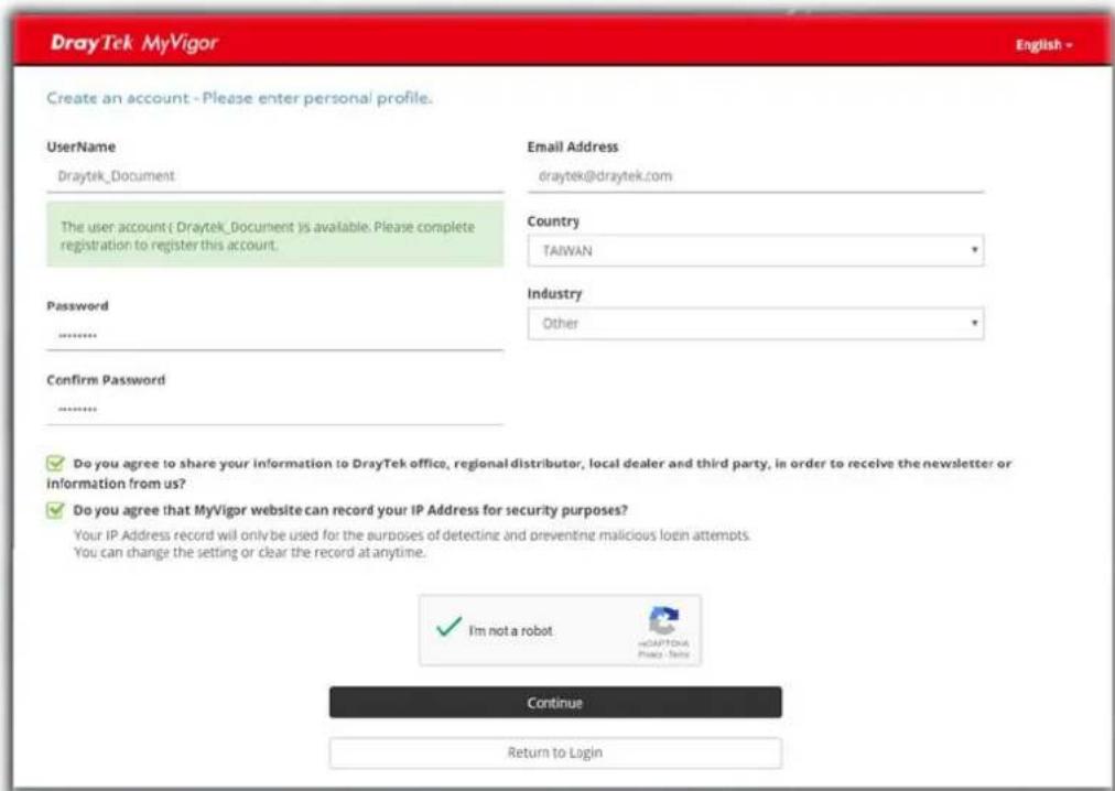
- Choose proper selection for your computer and click Continue.
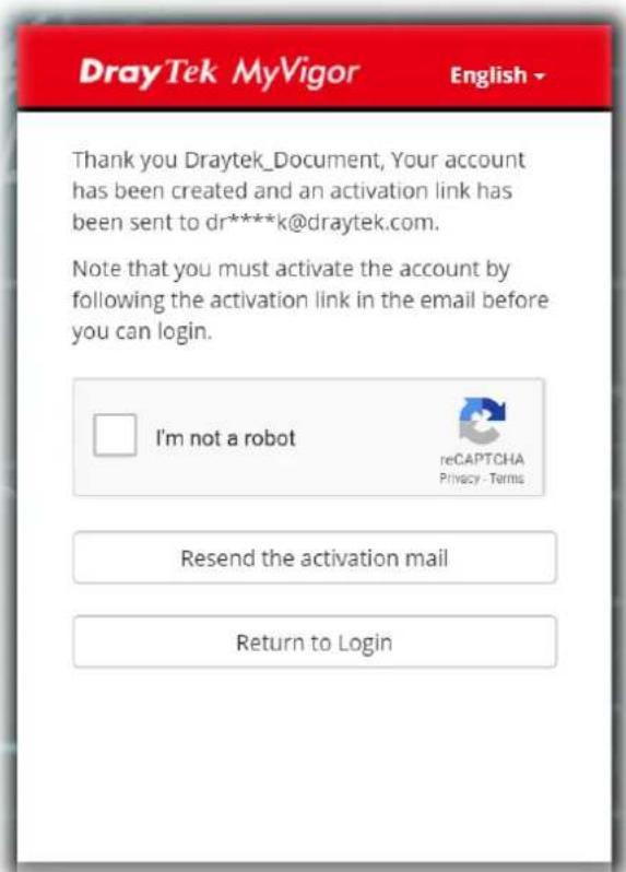
- Now you have created an account successfully.
- Check to see the confirmation email with the title of New Account Confirmation Letter from myvigor.draytek.com.
***** This is an automated message from myvigor.draytek.com. *****
Thank you (Mary) for creating an account.
Please click on the activation link below to activate your account
Link : Activate my Account
- Click the Activate my Account link to enable the account that you created. The following screen will be shown to verify the register process is finished. Please click Login.
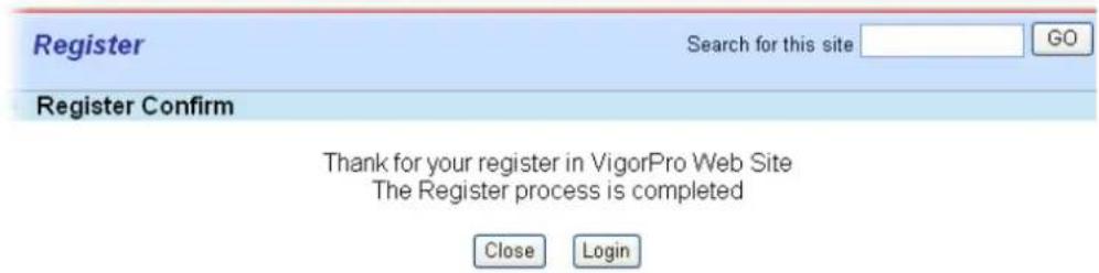
- When you see the following page, please type in the account and password (that you just created) in the fields of UserName and Password.
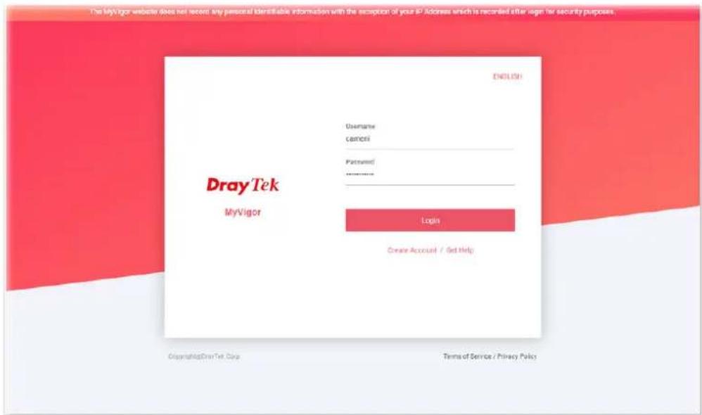
- Now, click Login. Your account has been activated. You can access into MyVigor server to activate the service (e.g., WCF) that you want.
A-2 How to Block Facebook Service Accessed by the Users via Web Content Filter / URL Content Filter
There are two ways to block the facebook service, Web Content Filter and URL Content Filter.
Web Content Filter,
Benefits: Easily and quickly implement the category/website that you want to block.
Note: License is required.
URL Content Filter,
Benefits: Free, flexible for customize webpage.
Note: Manual setting (e.g., one keyword for one website.)
I. Via Web Content Filter
-
Make sure the Web Content Filter license is valid.
-
Open CSM >> Web Content Filter Profile to create a WCF profile. Check Social Networking with Action, Block.
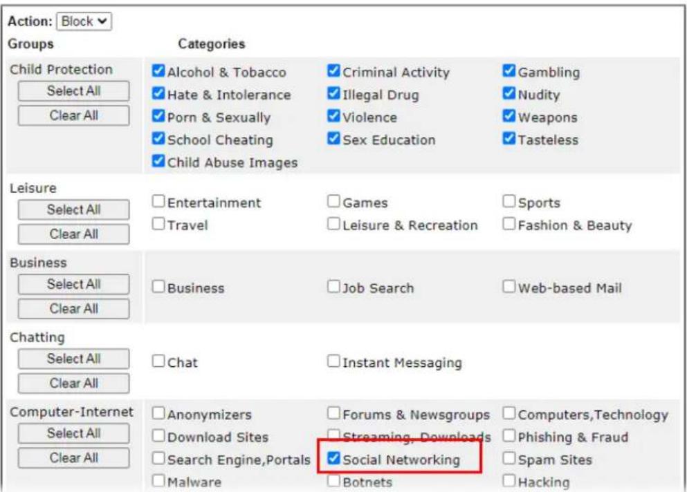
- Select this profile in Firewall>>General Setup>>Default Rule.
Firewall >> General Setup
![General Setup General Setup Default Rule Actions for default rule: Application Action/Profile Syslog Filter Pass Sessions Control 0 / 150000 Quality of Service None User Management None APP Enforcement None URL Content Filter None Web Content Filter None DNS Filter None [Create New] 1-Default Advance Setting Edit](/content/2026/05/813922/images/67bb39bf28c405727960abefd13a8a98c7fef8a951f26d7ed33e3eac81127080.jpg)

- Next time when someone accesses facebook via this router, the web page would be blocked and the following message would be displayed instead.
The requested Web page
from 192.168.2.114
to www.facebook.com/
that is categorized with [Social Networking]
has been blocked by Web Content Filter.
Please contact your system administrator for further information.
[Powered by DrayTek]
II. Via URL Content Filter
A. Block the web page containing the word of "Facebook"
-
Open Object Settings>>Keyword Object. Click an index number to open the setting page.
-
In the field of Contents, please type facebook. Configure the settings as the following figure.
Objects Setting >> Keyword Object Setup
Profile Index : 1
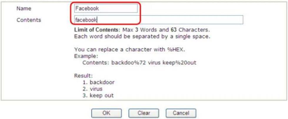
- Open CSM>>URL Content Filter Profile. Click an index number to open the setting page.
- Configure the settings as the following figure.
CSM >> URL Content Filter Profile
Profile Index: 1
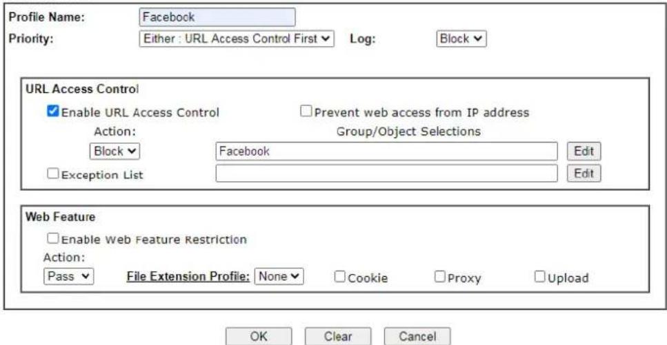
-
When you finished the above steps, click OK. Then, open Firewall>>General Setup.
-
Click the Default Rule tab. Choose the profile just configured from the drop down list in the field of URL Content Filter. Now, users cannot open any web page with the word "facebook" inside.
Firewall >> General Setup
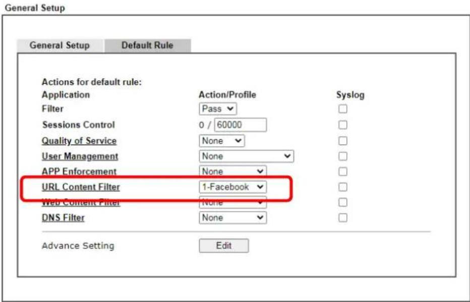
B. Disallow users to play games on Facebook
- Open Object Settings>>Keyword Object. Click an index number to open the setting page.
- In the field of Contents, please type apps.facebook. Configure the settings as the following figure.
Objects Setting >> Keyword Object Setup
Profile Index : 2
| Name | facebook-apps |
| Contents | apps facebook |
| Limit of Contents: Max 3 Words and 63 Characters. Each word should be separated by a single space. | |
| You can replace a character with %HEX. Example: Contents: backdoo%72 virus keep%20out | |
| Result: 1. backdoor 2. virus 3. keep out |

- Open CSM>>URL Content Filter Profile. Click an index number to open the setting page.
- Configure the settings as the following figure.
CSM >> URL Content Filter Profile
Profile Index: 2
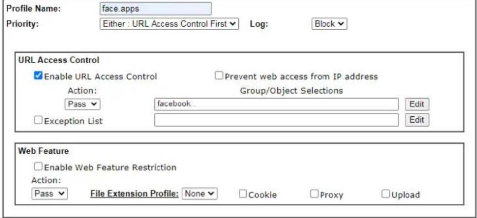

- When you finished the above steps, please open Firewall>>General Setup.
- Click the Default Rule tab. Choose the profile just configured from the drop down list in the field of URL Content Filter. Now, users cannot open any web page with the word "facebook" inside.
Firewall >> General Setup
General Setup
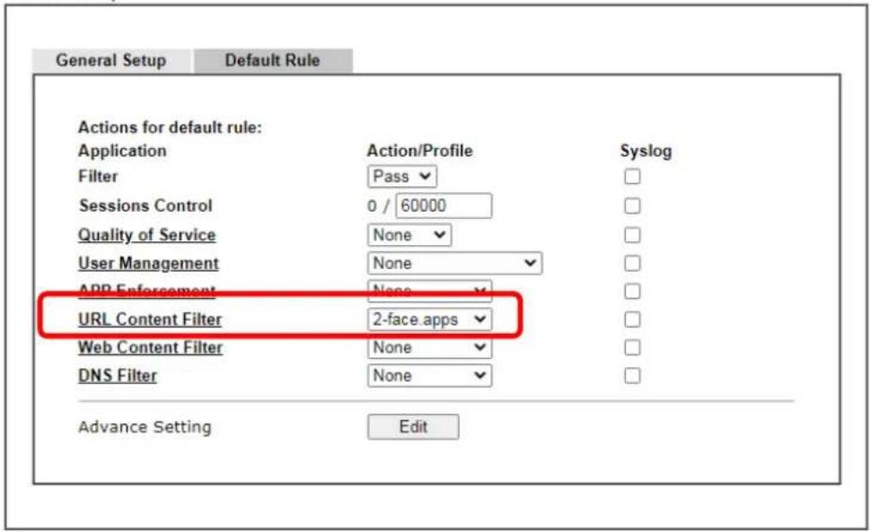
A-3 How to use APP Enforcement to block application like Facebook, YouTube or TeamViewer?
APP Enforcement helps network administrator to block applications on LAN network. Draytek routers provide a few categories to set up the profiles e.g., IM, P2P, Protocol, Stream, Remote control.
This section is going to demonstrate how to use APP Enforcement to block Facebook, Skype, YouTube and TeamViewer.

flowchart
graph LR
    A["LAN Client"] --> B["Vigor Router"]
    B --> C["Internet"]
1. Create an APP Enforcement Profile: Click on an Index number to create a new profile at CSM >> APP Enforcement Profile.
CSM >> APP Enforcement Profile
| APP Enforcement Profile Table: Set to Factory Default | |||
| Profile | Name | Profile | Name |
| 1. | 17. | ||
| 2. | 18. | ||
| 3. | 19. | ||
| 4. | 20. | ||
| 5. | 21. | ||
- Set up the details in the profile.
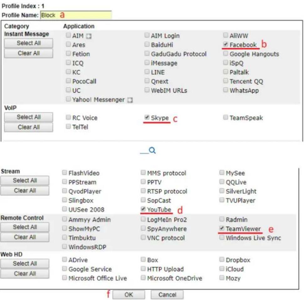
(a) Enter Profile Name.
(b) Choose the Facebook in Instant Message.
(c) Choose Skype in VoIP.
(d) Choose YouTube in Stream.
(e) Choose TeamViewer in Remote control.
(f) Click OK to save.
- Apply the APP Enforcement Profile to a Firewall Filter Rule. Go to Firewall >> Filter Setup, and click an available set.
| Set | Comments | Set | Comments |
| 1. | Default Call Filter | 7. | |
| 2. | Default Data Filter | 8. | |
| 3. | 9. | ||
| 4. | 10. | ||
| 5. | 11. | ||
| 6. | 12. |
- Click on a Filter Rule index to set up a filter.
Firewall >> Filter Setup >> Edit Filter Set
Filter Set 2
| Rules Enable | Comments | Direction | Src IP | Dst IP | Service Type | Action | CSM | Move Up | Move Down | |
| 1 | ☑ | xNetBios -> DNS | LAN/DMZ/RT/VPN-> WAN | Any | Any | TCP/UDP, Port: from 137~139 to 53 | Block Immediately | Down | ||
| 2 | ☐ | LAN/DMZ/RT/VPN-> WAN | Any | Any | Any | Pass Immediately | UP | Down | ||
| 3 | ☐ | LAN/DMZ/RT/VPN-> WAN | Any | Any | Any | Pass Immediately | UP | Down | ||
| 4 | ☐ | LAN/DMZ/RT/VPN-> WAN | Any | Any | Any | Pass Immediately | UP | Down | ||
| 5 | ☐ | LAN/DMZ/RT/VPN-> WAN | Any | Any | Any | Pass Immediately | UP | Down | ||
| 6 | ☐ | LAN/DMZ/RT/VPN-> WAN | Any | Any | Any | Pass Immediately | UP | Down | ||
| 7 | ☐ | LAN/DMZ/RT/VPN-> WAN | Any | Any | Any | Pass Immediately | UP | |||
Filter Set 1 2 3 4 5 6 7 8 9 10 11 12
Next Filter Set None ▼
Wizard Mode: most frequently used settings in three pages
■ Advance Mode: all settings in one page
- Set up the details in the profile.
Firewall >> Edit Filter Set >> Edit Filter Rule
Filter Set 2 Rule 2
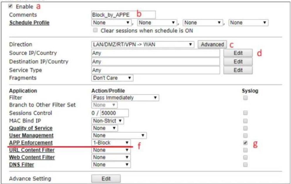




(a) Enable the Filter Rule.
(b) Put the comments of this rule.
(c) Select the Direction as LAN/DMZ/RT/VPN -> WAN.
(d) Edit the Source IP which should be blocked from the APP.
(e) Select Filter as Pass Immediately.
(f) Select APP Enforcement as the profile we created in Step 2.
(g) You may also check the Syslog if needed.
(h) Click OK to save.
- With the above configuration, LAN clients cannot be able to use the APP and website.

This site can't provide a secure connection
www.facebook.com sent an invalid response.
Try running Windows Network Diagnostics.
ERR_SSL_PROTOCOL_ERROR
Part V Management

System Maintenance

Bandwidth Management

User
Management
There are several items offered for the Vigor router system setup: System Status, TR-069, Administrator Password, User Password, Login Page Greeting, Configuration Backup, Configuration Export, Syslog / Mail Alert, Time and Date, SNMP, Management, Self-Signed Certificate, Reboot System, Firmware Upgrade, Activation, Internal Service User List, Dashboard Control and NAT Sessions
It is used to control the bandwidth of data transmission through configuration of Sessions Limit, Bandwidth Limit, and Quality of Servie (QoS).
It is a security feature which disallows any IP traffic (except DHCP-related packets) from a particular host until that host has correctly supplied a valid username and password.
V-1 System Maintenance
For the system setup, there are several items that you have to know the way of configuration: System Status, TR-069, Administrator Password, User Password, Login Page Greeting, Configuration Backup, Syslog / Mail Alert, Time and Date, Management, Panel Control, Reboot System, Firmware Upgrade, Internal Service User List, Dashboard Control and NAT Sessions.
Below shows the menu items for System Maintenance.
System Maintenance
System Status
TR-069
Administrator Password
User Password
Login Page Greeting
Configuration Backup
Configuration Export
Webhook
SysLog / Mail Alert
Time and Date
SNMP
Management
Self-Signed Certificate
Reboot System
Firmware Upgrade
Internal Service User List
Dashboard Control
Max Connection
Web User Interface
V-1-1 System Status
The System Status displays basic network information of Vigor router including LAN and WAN interface status. Also available is the current firmware version and firmware related information.
System Maintenance >> System Status
| Model Name | : Vigor3910 |
| Firmware Version | : 4.3.2.5 |
| Build Date/Time | : May 25 2023 11:23:39 |
| LAN | |||||
| MAC Address | IP Address | Subnet Mask | DHCP Server | DNS | |
| LAN1 | 00-1D-AA-4B-3E-80 | 192.168.1.100 | 255.255.255.0 | OFF | 8.8.8.8 |
| IP Routed Subnet | 00-1D-AA-4B-3E-80 | 192.168.0.1 | 255.255.255.0 | ON | 8.8.8.8 |
| WAN | |||||
| Link Status | MAC Address | Connection | IP Address | Default Gateway | |
| WAN1 | Disconnected | 00-1D-AA-4B-3E-81 | DHCP Client | --- | --- |
| WAN3 | Disconnected | 00-1D-AA-4B-3E-83 | DHCP Client | --- | --- |
| WAN5 | Disconnected | 00-1D-AA-4B-3E-85 | Static IP | 172.16.3.135 | 172.16.3.1 |
| WAN6 | Disconnected | 00-1D-AA-4B-3E-86 | DHCP Client | --- | --- |
| WAN7 | Disconnected | 00-1D-AA-4B-3E-87 | DHCP Client | --- | --- |
| WAN8 | Disconnected | 00-1D-AA-4B-3E-88 | DHCP Client | --- | --- |
| IPv6 | |||
| Address | Scope | Internet Access Mode | |
| LAN | FE80::5115:825B:68AE:EC3E/64 | Link | --- |
User Mode is OFF now.
Available settings are explained as follows:
| Item | Description |
| Model Name Displays the model name of the router. | |
| Firmware Version Displays the firmware version of the router. | |
| Build Date/Time Displays the date and time of the current firmware build. | |
| LAN | MAC Address- Displays the MAC address of the LAN Interface.IP Address- Displays the IP address of the LAN interface.Subnet Mask- Displays the subnet mask address of the LAN interface.DHCP Server- Displays the current status of DHCP server of the LAN interface.DNS- Displays the assigned IP address of the primary DNS. |
| WAN | Link Status- Displays current connection status of the WAN interface. |
| MAC Address- Displays the MAC address of the WAN Interface.Connection- Displays the connection type of the WAN interface..IP Address- Displays the IP address of the WAN interface.Default Gateway- Displays the assigned IP address of the default gateway. | |
| IPv6 | Address - Displays the IF Scope - Displays the scope of IPv6 address. For example, IPv6 Link Local is non-routable and can only be used for local connections.Internet Access Mode - Displays the connection mode of the WAN interface. |
V-1-2 TR-069
This device supports the TR-069 standard for remote management of customer-premises equipment (CPE) through an Auto Configuration Server, such as VigorACS.
V-1-2-1 ACS and CPE Settings
System Maintenance >> TR-069

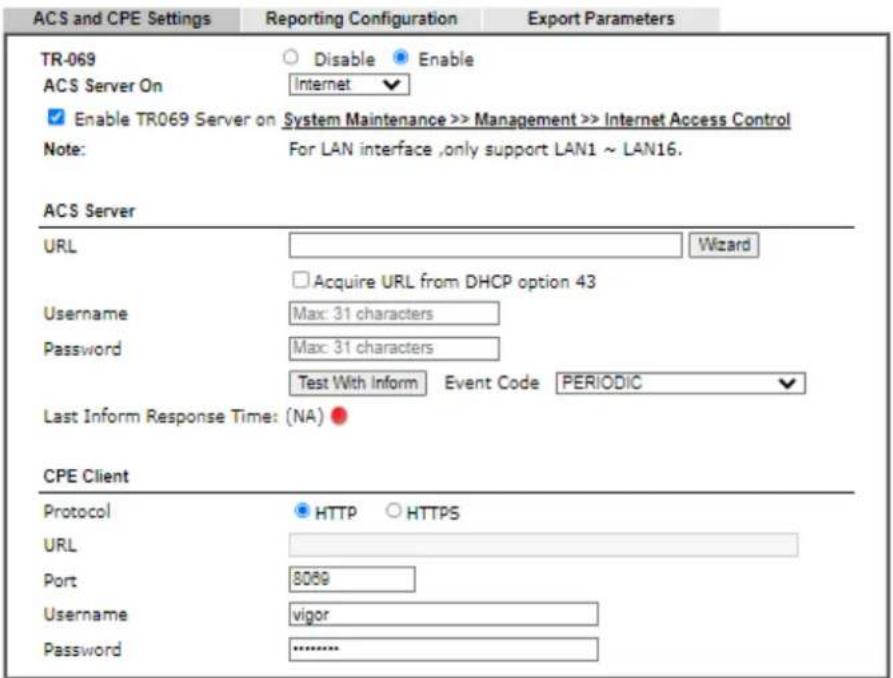
Periodic Inform Settings

STUN Settings
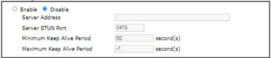
Apply Settings to APs/Switches
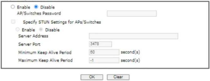
Available settings are explained as follows:
| Item | Description |
| TR-069 Enables or disables | TR-069 functionality. |
| ACS Server On | Choose the interface for connecting the router to the Auto Configuration Server. |
| Enable TR069 Server on System Maintenance >> Management >> Internet Access Control | If enabling, a user will be allowed to access into TR-069 from WAN. |
| ACS Server | This section specifies the settings of the ACS Server.URL - Enter the URL for connecting to the ACS. Please refer to the Auto Configuration Server user's manual for detailed information.Wizard - Click it to enter the IP address of VigorACS server, port number and the handler.Acquire URL form DHCP option 43 - Select to acquire the ACS URL from DHCP option 43.Usage/Password - Enter the credentials required to connect to the ACS server.Test With Inform - Click to send an inform message using the selected Event Code to test if the CPE is able to communicate with the VigorACS server.Event Code - Select an event for the inform test.Last Inform Response Time - Displays the time of the most recent Inform Response message received from the VigorACS. |
| CPE Client | This section specifies the settings of the CPE Client.Http / Https - Select Https if the connection is encrypted; otherwise select Http.Port - In the event of port conflicts, change the port number of the CPE.Usage and Password - Enter the username and password that the VigorACS will use to connect to the CPE. |
| Periodic Inform Settings | Enable - The default setting is Enable, which means the CPE Client will periodically connect to the ACS Server to update its connection parameters at intervals specified in the Interval Time field.Time Interval - Set interval time or schedule time for the router to send notification to CPE.Disable - Select Disable to turn off periodic notifications. |
| STUN Settings STUN allows | the ACS Server to connect to the CPE Client even when the client is behind a network address translator (NAT).Disable - The default setting is Disable.Enable - Please Enter the relational settings listed below:Server Address - Enter the IP address of the STUN server.Server STUN Port - Enter the port number of the STUN server.Minimum Keep Alive Period - If STUN is enabled, the CPE must periodically transmit binding requests to the server for the purpose of maintaining the binding with the Gateway. Enter the minimum interval betweenkeep-alive messages that the CPE client sends to the ACS server. The default setting is 60 seconds.Maximum Keep Alive Period - If STUN is enabled, the CPE must send binding request to the server for the purpose of maintaining the binding with the Gateway. Enter the maximum interval between keep-alive messages that the CPE client sends to the ACS server. A value of -1 indicates that no maximum period is specified. |
| Apply Settings to APs/Switches | This feature is able to apply TR-069 settings (including STUN and ACS server settings) to all of APs managed by Vigor router at the same time.Disable - TR-069 and Related settings will not be applied to VigorAPs.Enable - TR-069 settings will be applied to VigorAPs after clicking OK. The VigorAP password must be specified.AP/Switches Password - Enter the password of the VigorAP that you want to apply Vigor router's TR-069 settings.Specify STUN Settings for APs/Switches - After clicking the Enable radio button for Apply Settings to APs, if you want to apply specific STUN settings (i.e., different from the Vigor3910 STUN settings) to VigorAPs to meet specific requirements, check this box and enter the server IP address, server port, and minimum and maximum keep alive periods respectively. |
Select OK to save changes on the page, or Clear to reset all settings to factory defaults.
V-1-2-2 Reporting Configuration
Information related to the router's health are divided into several categories and listed in this field. After checking the item(s), Vigor router will arrange and send corresponding data to VigorACS as a reference for the system administrator.
System Maintenance >> TR-069 Setting
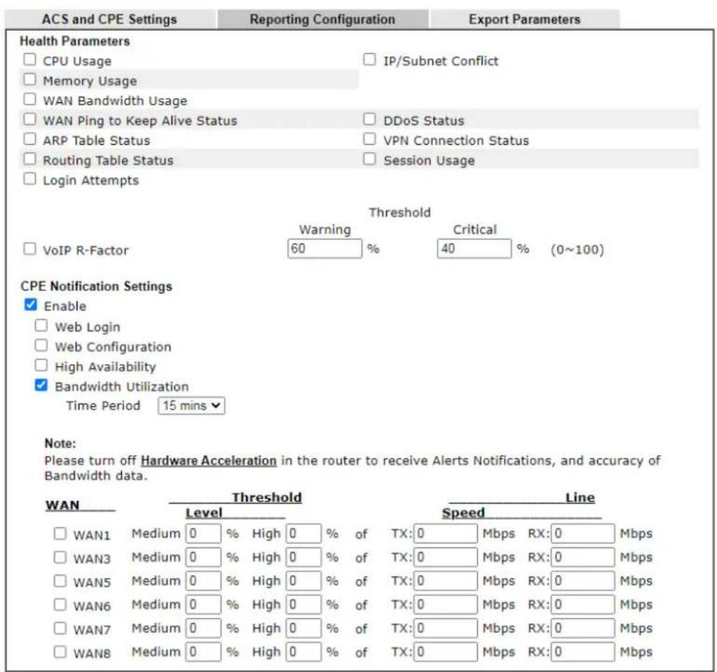

Available settings are explained as follows:
| Item | Description |
| Health Parameters Check the one that Vigor router will send the status information to VigorACSThreshold (for VoIP R-Factor) - Once the quality of VoIP is lower than warning limit value or critical limit value, the router will send the result to VigorACS. | |
| CPE Notification Settings | Enable - Check the box to select the notification item(s).Vigor router will send the utilization status to VigorACS. |
Click OK to save changes on the page.
V-1-2-3 Export Parameters
Click Export to save the TR-069 parameter settings as an ".xml".
System Maintenance >> TR-069 Setting
| ACS and CPE Settings | Reporting Configuration | Export Parameters |
| Export | ||
| Export tr069 parameters by xml. | ||
| Export | ||
V-1-3 Administrator Password
This page allows you to set or change the administrator password.
System Maintenance >> Administrator Password
Administrator Password
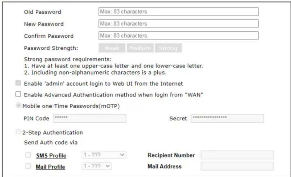
Note:
Password can contain only a-z A-Z 0-9 , ; : . " < > " + = - \ | ? @ # ^ ! ( )
Administrator Local User
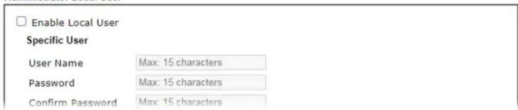
Available settings are explained as follows:
| Item | Description |
| Administrator Password The administrator can login web user interface of Vigor router to modify all of the settings to fit the requirements.Old Password - Enter the current password. The factory default is “admin”.New Password - Enter the new password. The maximum length of the password is 23 characters.Confirm Password - Enter the new password again for confirmation.Password Strength - Shows the security strength of the password specified above.Enable ‘admin’ account login to Web UI from the Internet - Select to allow the administrator to log in from the Internet. This option is enabled when Administrator Local User is enabled (see below).Use only advanced authentication method for Admin | |
| “WAN” login - Advanced authentication method can offer a more secure network connection. Select to require mOTP or 2-step authentication when logging in from the WAN.Mobile one-Time Password (mOTP) - Select to allow the use of mOTP passwords. Enter the PIN Code and Secret settings for getting one-time passwords.2-Step Auth code via SMS Profile and/or Mail Profile - Select the SMS and/ or Mail profiles and the destination SMS number and/ or email address for transmitting the password. | |
| Administrator Local User | Usually, the system administrator has the highest privilege to modify the settings on the web user interface of the Vigor router. However, in some cases, it might be necessary to have other users in LAN to access into the web user interface of Vigor router.This feature allows you to add more administrators who can then log in to the web interface, with the same privileges as the administrator.Enable Local User - Check the box to allow other users to administer the router.Specific User - Create the new user account as the local user. Then specify the authentication method (dividing into Basic and Advanced) for the user account.User Name - Enter a user name.Password - Enter the password for the local user.Confirm Password - Enter the new password again for confirmation.User Name and Password only - If selected, you need to enter a user name and password.Mobile one-Time Password (mOTP) - Select to allow the use of mOTP passwords. Enter the mOTP PIN Code and Secret that will be used to generate the one-time passwords.2-Step Authentication via SMS Profile and/or Mail Profile - Select the SMS and/ or Mail profiles and the destination SMS number and/ or email address for transmitting the password.Enable Advanced Authentication method when login from “WAN” - Advanced authentication method can offer a more secure network connection. Select to require mOTP or 2-step authentication when logging in from the WAN.Add - After entering the user name and password above, click this button to create a new local user. The new user will be shown on the Local User List immediately.Edit - If you wish to change a user in the Local User List, select it, perform the necessary modifications, and click this button to update the user.Delete - If you wish to delete a user in the Local User List, select it and click this button to remove it.Local User List - Shows all the users that are set up to administer the router. |
| Administrator LDAP Setting | Enable LDAP/AD login for admin users - Select to allow authentication using an LDAP/ Active Directory Server.LDAP Server Profiles Setup - Click to set up the LDAP/ ActiveDirectory server. |
| Administrator TACACS+ Setting | Enable TACACS+ login for admin users - If it is enabled, any user can access into the web user interface of Vigor router through the TACACS+ server authentication.Fallback to local Authentication - If it is enabled, the administrator can use other login methods for authentication once the TACACS+ server has no response. |
Click OK to save changes on the page, and you will be directed to the login screen. Please log in with the new password.
V-1-4 User Password
This page allows you to set new password for user operation.
System Maintenance >> User Password
√ Enable User Mode for simple web configuration User Password
Set to Factory Default

Note:
- Password can contain a-z A-Z 0-9, ; :." < > * + = | ? @ # ^ ! ( )
- Password can't be all asterisks(=). For example, '*' or '***' is illegal, but '123*' or '*'45' is OK.
OK
Available settings are explained as follows:
| Item | Description |
| Enable User Mode for simple web configuration | Check this box to enable User Mode for web user interface with the password typed here for simple web configuration. The simple web user interface settings differ from those on the full web user interface seen when logged in using the administrator password. |
| Password Enter the password | The maximum length of the password is 31 characters. |
| Confirm Password | Enter the password again for verification. |
| Password Strength Shows the security strength of the password specified above. | |
| Set to Factory Default Click to return to the factory default setting. | |
Click OK to save changes on the page, and you will be directed to the login screen. Please window will appear. Please log in with the new password.
Here are the steps involved in setting up the router for User Mode Access:
- Navigate to System Maintenance>>User Password in the web user interface.
- Check the box of Enable User Mode for simple web configuration to enable user mode operation. Enter a new password in the field of New Password and click OK.
System Maintenance >> User Password
√ Enable User Mode for simple web configuration User Password
Set to Factory Default

Note:
- Password can contain a-z A-Z 0-9, ; :." < > * + = | ? @ ≠ ^ ! ( )
- Password can't be all asterisks(∞). For example, '∞' or '∞∞' is illegal, but '123∞' or '45' is OK.
OK
- The following screen will appear. Simply click OK.
System Maintenance >> User Password
Active Configuration
Password
:
- Log out the Vigor router web user interface by clicking the Logout button.
- The following window will be shown. Enter the new user password in the Password field and click Login.
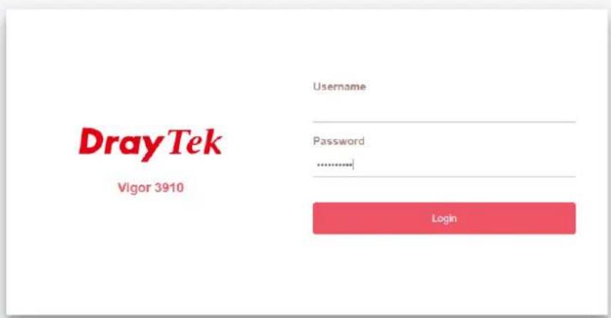
- The main screen with User Mode will be shown:
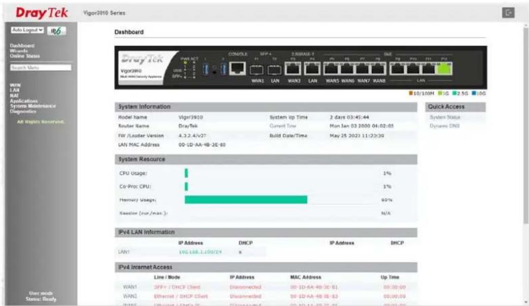
Only basic settings are available in User Mode. These are a subset of the Admin Mode settings.

Info
Setting in User Mode can be configured as same as in Admin Mode.
V-1-5 Login Page Greeting
When you want to access into the web user interface of Vigor router, the system will ask you to offer username and password first. At that moment, the background of the web page is blank and no heading will be displayed on the Login window. This page allows you to specify login URL and the heading on the Login window if you have such requirement.
This section allows you to customize the login page by adding a message and/or setting the page title.
System Maintenance >> Login Page Greeting
Login Page Greeting
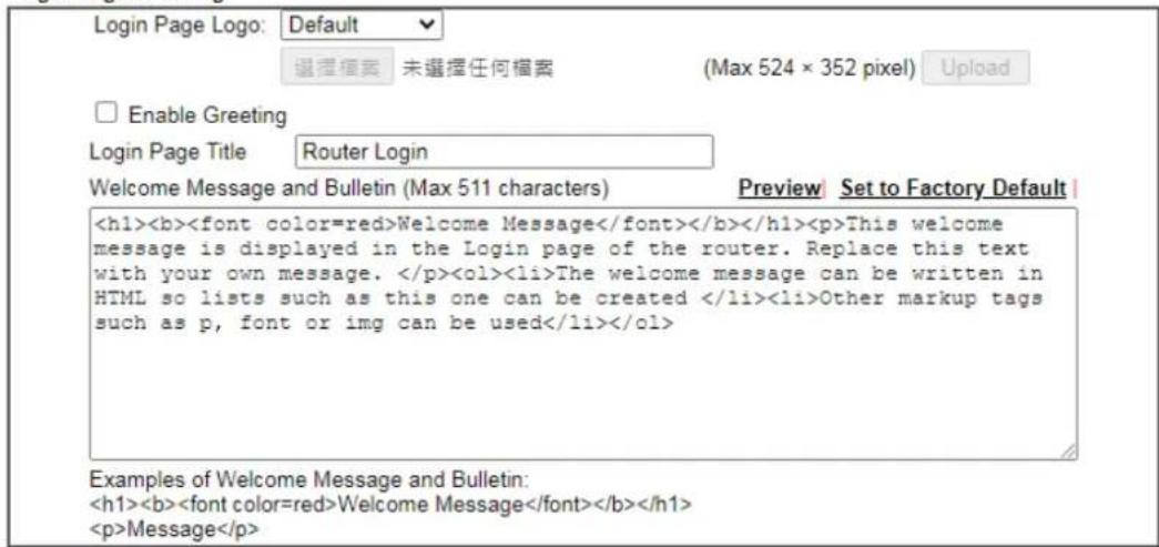
OK
Cancel
Available settings are explained as follows:
| Item | Description |
| Login Page Logo Set an image | ge which will be shown above the log in window.Default - The Enable Greeting feature is available to set the login page title.Blank - No image / no greeting.Upload a file - Choose an image file and click Upload. Later the selected image will be shown on the log in window. |
| Enable Greeting Check this | box to enable the login customization function. |
| Login Page Title Enter a brief | ef description (e.g., Welcome to DrayTek) which will be shown on the heading of the login dialog. |
| Welcome Message and Bulletin | Enter words or sentences here. It will be displayed for bulletin message. In addition, it can be displayed on the login dialog at the bottom.Note that do not enter URL redirect link here. |
| Preview Click to preview the | customized login window based on the settings entered on this page. |
| Set to Factory Default Click | to return to the factory default setting. |
Below shows an example of a customized login page with the values entered in the Login Page Title and Welcome Message and Bulletin fields.
DrayTek
Vigor 3910
Username
admin
Password
......
Login
Just for Carrie
Welcome Message
This welcome message is displayed in the Login page of the router. Replace this text with your own message.
- The welcome message can be written in HTML so lists such as this one can be created
- Other markup tags such as p, font or img can be used
V-1-6 Configuration Backup
This function allows the backup and restoration of Vigor router settings.
System Maintenance >> Configuration Backup
Configuration Backup / Restoration
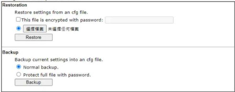
Available settings are explained as follows:
| Item | Description |
| Restore | Restore settings from an cfg file - Click the Select File button to specify a file to be restored or click USB Storage (if a USB storage disk connected) to choose the configuration file.This file is encrypted with password - Select to specify a password.Restore - Click to initiate restoration of configuration. If the backup file is encrypted, you will be asked to enter the password. |
| Backup Click it to perform the configuration backup of this router.Normal backup - Select to backup without a password.Protect full file with password- Select to encrypt the backup with a password. You will be prompted to enter the password as shown below:BackupBackup current settings into an cfg file.○ Normal backup.● Protect full file with password.Password (Max. 23 characters allowed)Confirm Password (Max. 23 characters allowed)Note: Only 1-9, A-Z, a-z, and ,::<>=|?@#^() are allowed.Backup● Password - Enter a new password for encrypting the configuration file.● Confirm Password - Enter the new password again for confirmation.Backup - Click to initiate the backup process. |
Backing up the Configuration
Follow the steps below to backup your configuration.
-
Go to System Maintenance >> Configuration Backup.
-
Click the Backup button, and the File Download dialog will be shown. Depending on your browser, you may be prompted to select a location to save the file, or the file may be saved in the default download location of your browser.
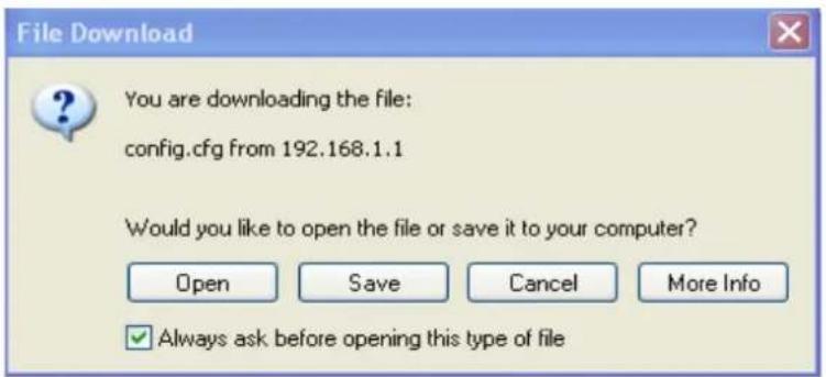
The configuration will download automatically to your computer as a file named config.cfg.
The above example is using Windows platform for demonstrating examples. The Mac or Linux platform will appear different windows, but the backup function is still available.

Info
Configuration Backup does not include certificates stored on the router. Please back up certificates separately by going to Certificate Management >> Certificate Backup.
Restoring the Configuration
-
Go to System Maintenance >> Configuration Backup. The following windows will be shown.
-
Click the Choose File button under Restoration to bring up the open file dialog box to select the configuration file to be uploaded and restored.
-
Click the Restore button and wait for few seconds.
V-1-7 Configuration Export
Configuration for Vigor3910 can be exported as an user-readable text-based (.exp) file which can be applied to other Vigor router.
In addition, it is possible to import an ".exp" file from other DrayTek routers onto the Vigor3910.
System Maintenance >> Configuration Export
Configuration Export / Import
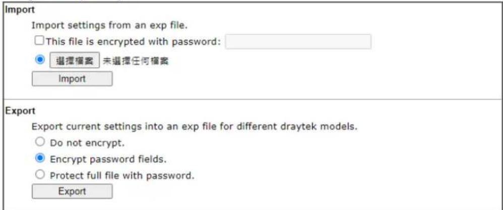
Available settings are explained as follows:
| Item | Description |
| Import | This file is encrypted with password - Check the box and enter a password for decrypting the configuration file (if the.exp file is encrypted).Click the Select File button to specify an exp file.Import - Click to import a configuration file. If the file is encrypted, you will need to enter the password set on the above password field. |
| Export Do not encrypt - The configuration file (.exp) will be output as an fully user-readable text-based file.Encrypt password fields - The configuration file (.exp) will be output as a user-readable text-based file except for password related fields (user passwords will be encrypted).Protect full file with password - The configuration file is protected by full encryption. The password will be needed when importing the "exp" file on Vigor router.Export - Click it to export the configuration of Vigor router as a file with the extension of "exp". | |
V-1-8 Webhook
Vigor router will send a report (webhook message) including WAN up, down, CPU usage, memory usage and etc. to a monitoring server periodically.
System Maintenance >> Webhook
□ Enable
Monitoring Server URL
Report Period (1\~1440 minutes)

OK
Cancel
Note
Vigor Router will use HTTPS to send the Webhook message by default. When the Monitoring Server supports HTTP only, please configure the URL with HTTP://.
Available settings are explained as follows:
| Item | Description |
| Enable Select it to enable this function. | |
| Monitoring Server URL Enter the URL of a server. | |
| Report Period | Define the interval time for each report to be sent. |
Select OK to save changes on the page.
V-1-9 Syslog/Mail Alert
SysLog function is provided for users to monitor router.
System Maintenance >> SysLog / Mail Alert Setup
SysLog / Mail Alert Setup
SysLog Access Setup
Enable
Syslog Save to:
Syslog Server
□USB Disk
Maximum Syslog folder space 1 GB When Syslog folder is full: Overwrite oldest logs
Router Name
TEST2_3910
Primary Syslog Server
Server IP/Hostname
Destination Port
192.168.13.10
514
Secondary Syslog Server
Server IP/Hostname
Destination Port
514
Mail Syslog
□Enable
Enable syslog message:
√ Firewall Log
VPN Log
User Access Log / Hotspot User Information
WAN Log
Router/DSL information
Mail Alert Setup
□Enable
Interface
SMTP Server
SMTP Port
Mail To
Sender Address
Connection Security
Authentication
Username
Password
Enable E-Mail Alert:
DoS Attack
APPE
VPN LOG
Debug Log
Download
Note:
- USB Syslog space is available from 256-1024 MB or 1-16 GB.
- Mail Syslog cannot be activated unless USB Disk is ticked for "Syslog Save to".
- Mail Syslog feature will send the Syslog when it is full.

Clear
Available settings are explained as follows:
| Item | Description |
| SysLog Access Setup | Enable - Check Enable to activate function of syslog.Syslog Save to - Check Syslog Server to save the log to Syslog server. Check USB Disk to save the log to the attached USB storage disk.Maximum Syslog folder space - Set the storage space as 1 GB or 1000MB.When Syslog folder is full - When Syslog folder is full, simply overwrite the oldest logs or stop logging. |
| Router Name | Shows the name of the router set in System Maintenance >> Management. This name will be used to identify the router in the Syslog entries.To set or modify the router name, click the hyperlink and you will be taken to System Maintenance >> Management where you can enter the value. |
| Primary Syslog Server / Primary Syslog Server / Secondary Syslog Server - Vigor | |
| Secondary Syslog Server | router will send the data to Syslog server for analysis based on the server settings configured here. It might send to both servers simultaneously if primary and secondary servers are set; or send to either one of the servers which has been set here.Server IP Address /Hostname - Enter the IP address / hostname of the Syslog server.Destination Port - Enter the port for the Syslog server.Mail Syslog - Select to enable sending Syslog messages by email.Enable syslog message - Select the events to be recorded by syslog. |
| Mail Alert Setup Enable - Select to enable the Mail Alert.Send a test e-mail - Click to send a test email message using the settings below.Interface - Specify the WAN interface for a mail passing through.SMTP Server - Enter the address of the SMTP server used to send email.SMTP Port - Enter the port of the SMTP server. Default setting is 25.Mail To - Enter the email address of the recipient.Sender Address - Assign a mail address for sending mails out.Connection Security - Select a method (Plaintext, SSL or StartTLS) to ensure the connection security. SSL means to use port 465 for SMTP server for some e-mail server uses https as the transmission method.Accept using plain text if StartTLS connection failed.Force StartTLS. Stop if StartTLS connection failed.Authentication - Select this checkbox and enter the username and password if the SMTP server requires authentication.User Name - Enter the user name for authentication.Password - Enter the password for authentication.Enable E-mail Alert - Select the event types that will trigger email alerts. | |
Select OK to save changes on the page, or Clear to reset all settings to factory defaults.
To view the Syslog message, please follow the steps below:
-
On the Syslog / Mail Alert Setup screen, enter the monitor PC's IP address in the Server IP Address field.
-
On the Syslog / Mail Alert Setup screen, enter the monitor PC's IP address in the Server IP Address field.

- In the Syslog application, select the router you wish to monitor. Rember to select the network adapter to be used to connect to the router under Network Information, or else Syslog traffic cannot be received from the router.
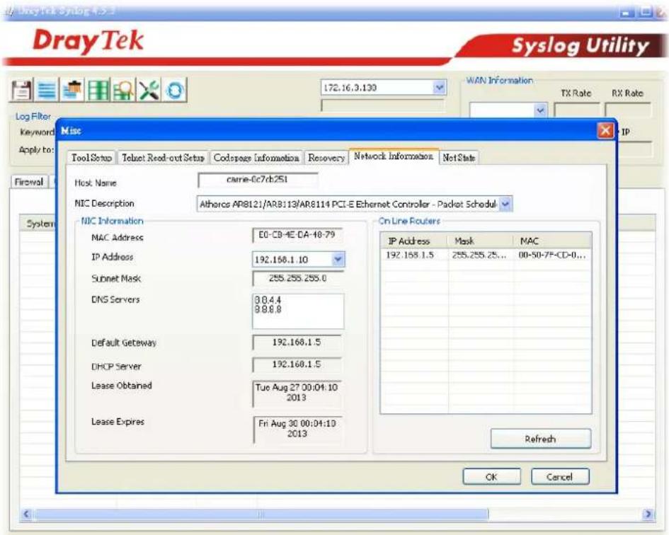
V-1-10 Time and Date
This section allows you to configure settings related to the system date and time.
System Maintenance >> Time and Date
Time Information
| Current System Time | 2022 Dec 29 Thu 17 : 24 : 25 | Inquire Time |
Time Setup
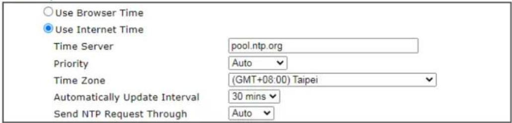

Available settings are explained as follows:
| Item | Description |
| Current System Time | Click Inquire Time to retrieve the current time from the time server. |
| Use Browser Time Select this option to let the router set its system time using the time reported by the web browser. | |
| Use Internet Time Select this option to let the router set its system time by retrieving time information from the specified network time server using the Network Time Protocol (NTP). | |
| Time Server Enter the IP address / Host name of the time server. | |
| Priority | Select Auto or IPv6 First as the priority. |
| Time Zone Select the time zone where the router is located. | |
| Automatically Update Interval | Select the time interval at which the router updates the system time. |
| Send NTP Request Through | Specify a WAN interface to send NTP request for time synchronization. |
Select OK to save changes on the page, or Cancel to discard changes without saving.
V-1-11 SNMP
This section allows you to configure settings for SNMP and SNMPV3 services.
The SNMPv3 is more secure than SNMP through the use of encryption (supports AES and DES) and authentication (supports MD5 and SHA) for the management needs.
System Maintenance >> SNMP
SNMP Setup
Enable SNMP Agent
Enable SNMPv3 Agent
USM User
Auth Algorithm
Auth Password
Privacy Algorithm
Privacy Password
Enable SNMPv2C Agent
Get Community
Set Community
Manager Host IP(IPv4)
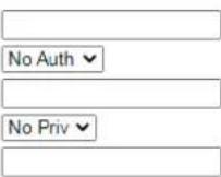
IP
Index
Manager Host IP(IPv6)
Index
IPv6 Address
/ Prefix Length


IP
Trap Community
Notification Host IP(IPv4)
Index
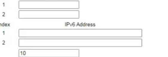
Notification Host IP(IPv6)
Trap Timeout
Enable SNMPv1 Agent
IPv6 Address
OK
Cancel
Note:
SNMP service also shall be enabled for Internet access in System Maintenance >> Management.
Available settings are explained as follows:
| Item | Description |
| Enable SNMP Agent | Check to enable SNMP function. Then, enable SNMPv1 agent, SNMv2C, and / or SNMPv3 agent. |
| Enable SNMPv3 Agent Check to enable SNMPv3 function. | |
| USM User USM means user-based security mode.Enter the username to be used for authentication. The maximum allowed length is 23 characters. | |
| Auth Algorithm Choose one of the hashing methods to be used with the authentication algorithm. | |
| Auth Password Enter a password for authentication. The maximum allowed | |
| length is 23 characters. | |
| Privacy Algorithm Choose an encryption method as the privacy algorithm. | |
| Privacy Password Enter a password for privacy. The maximum allowed length is 23 characters. | |
| Enable SNMPv2C Agent Check to enable SNMPv2C function. | |
| Get Community Enter the Get Community string. The default setting is public. Devices that send requests to retrieve information using get commands must pass the correct Get Community string.The maximum allowed length is 23 characters. | |
| Set Community Enter the Set Community string. The default setting is private. Devices that send requests to change settings using set commands must pass the correct Set Community string.The maximum length of the text is 23 characters. | |
| Manager Host IP (IPv4) Enter the IPv4 address of hosts that are allowed to issue SNMP commands. If this field is left blank, any IPv4 LAN host is allowed to issue SNMP commands. | |
| Manager Host IP (IPv6) Enter the IPv6 address of hosts that are allowed to issue SNMP commands. If this field is left blank, any IPv6 LAN host is allowed to issue SNMP commands. | |
| Trap Community | Enter the Trap Community string. The default setting is public. Devices that send unsolicited messages to the SNMP console must pass the correct Trap Community string.The maximum length of the text is 23 characters. |
| Notification Host IP (IPv4) | Enter the IPv4 address of hosts that are allowed to be sent SNMP traps. |
| Notification Host IP (IPv6) | Enter the IPv6 address of hosts that are allowed to be sent SNMP traps. |
| Trap Timeout The default setting is 10 seconds. | |
| Enable SNMPv1 Agent Check to enable SNMPv1 function. | |
Select OK to save changes on the page, or Cancel to discard changes without saving.
V-1-12 Management
This page allows you to manage the settings for Internet/ LAN Access Control, Access List from Internet, Management Port Setup, TLS/ SSL Encryption Setup, CVM Access Control and Device Management.
The management pages for IPv4 and IPv6 protocols are different.
V-1-12-1IPv4 Management Setup
System Maintenance >> Management

| IPv4 Management Setup | IPv6 Management Setup | LAN Access Setup |
| Router Name TEST2_3910 | ||
| □ Default:Disable Auto-Logout □ Enable Validation Code in Internet/LAN Access Note: IE8 and below version does NOT support DrayOS CAPTCHA auth code. | Management Port Setup ○ User Define Ports ○ Default Ports Telnet Port 23 (Default: 23) HTTP Port 80 (Default: 80) HTTPS Port 443 (Default: 443) FTP Port 21 (Default: 21) TR069 Port 8069 (Default: 8069) SSH Port 22 (Default: 22) | |
| Internet Access Control ✓ Allow management from the Internet Domain name allowed □ FTP Server ✓ HTTP Server □Enforce HTTPS Access ✓ HTTPS Server □ Telnet Server ✓ TR069 Server □ SSH Server □ SNMP Server □ Disable PING from the Internet | Note: Ports 8001 and 8043 are used for Hotspot Web Portal. | |
| Loopback Interface □ Enable Loopback Interface LAN2 Note: 1. Management from WAN only available using Loopback IP, the WAN IP will not respond. 2. Source IP used for TR069,NTP,RADIUS/TACACS+,SYSLOG,SNMP. | Brute Force Protection ✓ Enable brute force login protection ✓ FTP Server ✓ HTTP Server ✓ HTTPS Server ✓ Telnet Server ✓ TR069 Server ✓ SSH Server ✓ VPN Server Maximum login failures 5 times Penalty period 300 seconds | |
| Access List from the Internet □ Apply Access List to PING List Type Index Description | Blocked IP List | |
| 1 IP Object None | TLS/SSL Encryption Setup ✓ Enable TLS 1.2 ✓ Enable TLS 1.1 ✓ Enable TLS 1.0 □ Enable SSL 3.0 | |
| 2 IP Object None | ||
| 3 IP Object None | ||
| 4 IP Object None | ||
| 5 IP Object None | ||
| 6 IP Object None | ||
| 7 IP Object None | ||
| 8 IP Object None | ||
| 9 IP Object None | ||
| 10 IP Object None | ||
| Note: Access list type: Hostname, single IP address supported for corresponding domain name. | AP Management ✓ Enable AP Management ✓ Device Management □ Respond to external device | |
OK
Available settings are explained as follows:
| Item | Description |
| Router Name Enter the router name as provided by ISP. | |
| Default: Disable Auto-Logout | If enabled, the auto-logout function for the web user interface will be disabled. The web user interface will not terminate until you manually click the Logout icon. The web user interface will not terminate until you manually click the Logout icon. |
| Enable Validation Code in Internet/LAN Access | If enabled, Vigor router will require users to enter a validation code as shown in an image when they log in. |
| Internet Access Control Allow management from the Internet - Enable the checkbox to allow system administrators to login from the Internet, and then select the specific services that are allowed to be remotely administered.Domain name allowed - This setting is only available if DNS filtering is enabled, applying DNS filter profile in firewall rules, or enabling DNS Filter Local Setting. The router will only allow connections to the WebUI using domain addresses configured in either DDNS profiles or this section.If DNS filtering is disabled, this setting will be disabled, and any domain address that resolves to the router's WAN IP address can be used to connect to the WebUI.Disable PING from the Internet - Select to reject all PING packets from the Internet. For increased security, this setting is enabled by default. | |
| Loopback Interface | A loopback interface is a logical virtual interface created on a router simulating a real interface. This can be used to connect to management services such as Web (HTTPS), SNMP, ACS (TR069), Syslog, or SSH as well as authentication services such as TACACS+ or RADIUS instead of using a LAN IP. For the authentication function, using the dedicated loopback address will reduce the administrative overhead since there is no need to add multiple router IP addresses to the AAA server. In addition, security will be enhanced by isolating authentication from the user network.Using a loopback address means the virtual interface is always up, especially when the CPE has multiple WAN interfaces. For example, if BGP connected on WAN1 is down, management and AAA traffic can be routed to the defined loopback interface through the VPN tunnel connected on WAN2.Another benefit is that the loopback IP can be an IP address (with a 32-bit mask). This means that the interface is not assigned to any LAN port, which improves security and saves a lot of IP address space. We can imagine that if we assign 24-bit mask IPs to many managed routers, there will be insufficient network IPs.Enable Loopback Interface - Select to enable the function of Loopback Interface.LAN#- Select a LAN subnet as the Loopback Interface. |
| Access List from the Internet | The ability of system administrators to log into the router can be restricted to up to 10 specific hosts or networks.Apply Access List to PING - When this option is checked and Disable PING from the Internet is unchecked, pings originating from the Internet will be accepted only if they are from one of the IP addresses and/or subnet masks specified below. This option has no effect if Disable PING from the Internet is checked, which blocks all pings from the Internet.Type - Select IP Object or Hostname.Index - Select the index number of a configured IP object, keyword object or IP group object.Description - Shows a brief comment for the selected IP object (with subnet mask). |
| Management Port Setup User | Define Ports - Check to specify user-defined port numbers for the Telnet, HTTP, HTTPS, FTP, TR-069 and SSH servers.Default Ports - Check to use standard port numbers for the Telnet and HTTP servers. |
| Brute Force Protection | Any client trying to access into Internet via Vigor router will be asked for passing through user authentication. Such feature can prevent Vigor router from attacks when a hacker tries every possible combination of letters, numbers and symbols until find out the correct combination of password.Enable brute force login protection - Select to enable detection of brute force login attempts.Maximum login failure - Specify the maximum number of failed login attempts before further login is blocked.Penalty period - Set the lockout time after maximum number of login attempts has been exceeded. The user will be unable to attempt to log in until the specified time has passed.Blocked IP List - Display, in a new browser window, IP addresses that are currently blocked from logging into the router. |
| TLS/SSL Encryption Setup | Enable SSL 3.0 and TLS 1.0/1.1/1.2 - Check the box to enable SSL 3.0/ 1.0/ 1.1/ 1.2 encryption protocols.For improved security, the HTTPS and SSL VPN servers that are built into the router have been upgraded to TLS 1.x protocol. If you are using an old web browser (eg. IE 6.0) or an old version of the SmartVPN Client, you may need to enable SSL 3.0 to connect to the router. However, it is recommended that you instead upgrade your web browser or SmartVPN client to a version that supports TLS protocols that are far more secure than SSL. |
| AP Management Enable AP | Management - Check to enable the access point management function. If not, menu items related to Central Management>>AP will be hidden. |
| Device Management | Check to enable the device management function.Respond to external device - If selected, Vigor3910 will function as a slave device. When an external device (masterdevice) sends packets to the Vigor3910 to attempt to manage it, the Vigor3910 will respond to the request coming from the external device which is able to manage Vigor3910. |
Select OK to save changes on the page.
V-1-12-2 IPv6 Management Setup
System Maintenance >> Management

| IPv4 Management Setup | IPv6 Management Setup | LAN Access Setup | ||
| Management Access Control □Allow management from the Internet □Telnet Server (Port: 23) □HTTP Server (Port: 80) □Enforce HTTPS Access □HTTPS Server (Port: 443) □SSH Server (Port: 22) □SNMP Server (Port: 161) ✓Disable PING from the Internet IPv6 Address Security Option ✓Enable Random Interface Identifiers(IIDs) instead of EUI-64 IIDs | ||||
| Access List from the Internet □Apply Access List to PING | ||||
| List | Type | Index | Description | |
| 1 | IPv6 Object | None | ||
| 2 | IPv6 Object | None | ||
| 3 | IPv6 Object | None | ||
| 4 | IPv6 Object | None | ||
| 5 | IPv6 Object | None | ||
| 6 | IPv6 Object | None | ||
| 7 | IPv6 Object | None | ||
| 8 | IPv6 Object | None | ||
| 9 | IPv6 Object | None | ||
| 10 | IPv6 Object | None | ||
| Note: 1Telnet / Http server port is the same as IPv4. 2Access list type: Hostname, single IP address supported for corresponding domain name. | ||||
OK
Available settings are explained as follows:
| Item | Description |
| Management Access Control | Allow management from the Internet - Select to allow system administrators to login from the Internet, and then select the specific services that are allowed to be remotely administered.Disable PING from the Internet - Select to reject all PING packets from the Internet. For increased security, this setting is enabled by default. |
| IPv6 Address Security Option | Enable Random Interface Identifiers (IIDs)... - The IPv6 address will be generated randomly but not using LAN/ WAN MAC to prevent the attack from the hacker. |
| Access List from the Internet | The ability of system administrators to log into the router can be restricted to up to 10 specific hosts or networks.Apply Access List to PING - When this option is checked and Disable PING from the Internet is unchecked, pingsoriginating from the Internet will be accepted only if they are from one of the IP addresses and/or subnet masks specified below. This option has no effect if Disable PING from the Internet is checked, such that no pings from the Internet are accepted.Type - Select IPv6 Object or Hostname.Index - Select the index number of a configured IPv6 object. |
Select OK to save changes on the page.
V-1-12-3 LAN Access Control
System Maintenance >> Management


Available settings are explained as follows:
| Item | Description |
| Allow management from LAN | Enable the checkbox to allow system administrators to login from LAN interface. There are several servers provided by the system which allow you to manage the router from LAN interface. Check the box(es) to specify. |
| Apply To Subnet | Check the LAN interface for the administrator to use for accessing into web user interface of Vigor router. Index in IP Object- Type the index number of the IP object profile. Related IP address will appear automatically. |
Select OK to save changes on the page.
V-1-13 Self-Signed Certificate
A self-signed certificate is a unique identification for the device (e.g., Vigor router) which generates the certificate by itself to ensure the router security. Such self-signed certificate is signed with its own private key.
The self-signed certificate can be used for services such as SSL VPN and HTTPS. In addition, it can be created for free by using a wide variety of tools.
System Maintenance >> Self-Signed Certificate
Self-Signed Certificate Information
| Certificate Name : | self-signed |
| Issuer : | C=TW, ST=HsinChu, L=HuKou, O=DrayTek Corp., OU=DrayTek Support, CN=Vigor Router |
| Subject : | C=TW, ST=HsinChu, L=HuKou, O=DrayTek Corp., OU=DrayTek Support, CN=Vigor Router |
| Subject Alternative Name : | DNS:www.draytek.com |
| Valid From : | Jun 15 12:38:44 2022 GMT+02:00 |
| Valid To : | Jul 15 12:38:44 2023 GMT+02:00 |
| PEM Format Content : |
Note:
- Please setup the System Maintenance >> Time and Date correctly before you try to regenerate a self-signed certificate!!
- The Time Zone MUST be setup correctly!!
Regenerate
Click Regeneration to open Regenerate Self-Signed Certificate window.
Regenerate Self-Signed Certificate
| Certificate Name | self-signed |
| Subject Alternative Name | |
| Type | IP Address ▼ |
| IP | |
| Subject Name | |
| Country (C) | |
| State (ST) | |
| Location (L) | |
| Organization (O) | |
| Organization Unit (OU) | |
| Common Name (CN) | |
| Email (E) | |
| Key Type | RSA ▼ |
| Key Size | 2048 Bit ▼ |
Generate
Enter all requested information including certificate name (used to differentiate different certificates), subject alternative name type and relational settings for subject name. Then click GENERATE.
V-1-14 Reboot System
The Web user interface may be used to restart your router. Click Reboot System from System Maintenance to bring up the following page.
System Maintenance >> Reboot System
Reboot System
Do you want to reboot your router?
Using current configuration (Fast reboot)
○ Using current configuration (Normal reboot)
○ Using factory default configuration
○ Wipe out all data
Reboot Now
Auto Reboot Time Schedule
Schedule Profile : None ▼, None ▼, None ▼, None ▼
Note:
Action and Duration Time settings will be ignored.
OK Cancel
Available settings are explained as follows:
| Item | Description |
| Reboot System | Select one of the following options, and press the Reboot Now button to reboot the router.Using current configuration (Fast reboot/Normal reboot) - Select this option to reboot the router using the current configuration.Fast reboot- Reboot the router quickly by a certain daemon.Normal reboot- Reboot the router with current configurations slowly and completely.Using factory default configuration- Select this option to reset the router's configuration to the factory defaults before rebooting.Wipe out all data- Select this option to wipe out all data. |
| Auto Reboot Time Schedule | Schedule Profile- Select up to 4 user-configured schedules to reboot the router on a scheduled basis. |
Select OK to save changes on the page, or Cancel to discard changes without saving.

Info
When the system pops up Reboot System web page after you configure web settings, please click Reboot Now to reboot your router for ensuring normal operation and preventing unexpected errors of the router in the future.
V-1-15 Firmware Upgrade
Click System Maintenance>> Firmware Upgrade to upgrade firmware upgrade.
System Maintenance >> Firmware Upgrade

Firmware Version Status
Current Firmware Version: 4.3.2.4
Latest Firmware Version: 4.3.2.4
Download Directly
Latest Firmware Detail
Download Link: https://www.draytek.co.uk/support/
Web Firmware Upgrade
Select a firmware file.
選擇檔案 未選擇任何檔案
Click Upgrade to upload the file.
Upgrade
Preview
Note:
- Upgrade using the ALL file will retain existing router configuration, whereas using the RST file will reset the configuration to factory defaults.
- For firmware "downgrading", please consider using "restore backup firmware with config" to avoid potential config compatibility issue.
Available settings are explained as follows:
| Item | Description |
| Firmware Versiono Status | Check The Latest Firmware - Click to check for updated firmware.Any available new firmware files will be displayed and you can download any one of them by clickingDownload. After the file has been downloaded, click Select followed by Upgrade to perform the firmware upgrade. |
| Web Firmware Upgrade | ClickBrowse... to select the firmware file, followed byUpgradeto start the upgrade process, orPreviewto display detailed information about the selected firmware file: |
V-1-16 Internal Service User List
User profiles (clients) defined and enabled in User Management>>User Profile will be displayed in this page.
Such page allows you to turn on or turn off security authentication service (offered by internal RADIUS and/or Local 802.1X) for each user profile without accessing into the User Management configuration page.
System Maintenance >> Internal Service User List


Note:
- Only the user profiles which is enabled in User Management >> User Profile will be listed here.
- If you enable RADIUS or Local 802.1X for a user profile here, it will use the default authentication methods; however, you may change its authentication methods via User Management >> User Profile.
Available settings are explained as follows:
| Item | Description |
| User Name Display the name | of the existed user profile. To modify the detailed settings, simply click the user name link to access into the web page for modification. |
| Radius Check the box to turn | on the security authentication service offered by internal RADIUS server for the user profile. Uncheck the box to turn off ecurity authentication service offered by internal RADIUS server for the user profile. If you check the box next to such item, all of the user profiles listed in this page will be enabled with RADIUS service enabled vice versa. |
| Local 802.1X Check the box | to turn on the security authentication service offered by Local 802.1X server for the user profile. Uncheck the box to turn off ecurity authentication service offered by Local 802.1X server for the user profile. If you check the box next to such item, all of the user profiles listed in this page will be enabled with Local 802.1X service enabled; vice versa. |

Info
For the detailed setting (such as IP address, port number) configuration of internal RADIUS, refer to Applications>>RADIUS/TACACS+.
V-1-17 Dashboard Control
There are nine groups of setting information which can be displayed on Dashboard as a reference for administrator/user. Except for Front Panel and System Information, the settings information regarding to the groups listed on this page can be hidden if required.
System Maintenance >> Dashboard Control
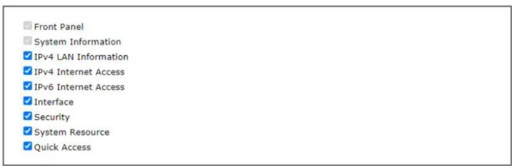

V-1-18 Max Connection
Set the maximum NAT session number.
Max Connection

Note:
It is recommended to choose a max. session number that just satisfies your need. Since a higher max. session number consumes more memory and leaves less memory for other features.
V-2 Bandwidth Management
Sessions Limit
When LAN clients share a common public IP address by means of Network Address Translation (NAT), the router must track NAT sessions so that traffic to and from the WAN can reach the intended destinations. There is a finite number of sessions that can be tracked by the router, and by setting session limits will ensure that the router does not run out of resources. This is especially important when P2P applications are used. P2P applications, such as BitTorrent, that attempt to simultaneously establish connections to as many WAN hosts as possible.
Bandwidth Limit
Bandwidth Limit ensures LAN clients get their fair share of network bandwidth by placing restrictions on upstream and downstream network speeds.
Quality of Service (QoS)
QoS (Quality of Service) ensures that all LAN clients receive their fair share of bandwidth that is required for applications to function properly and efficiently.
Without QoS, it is possible that certain applications may consume excessive network resources that they degrade performance of more important applications, especially ones that are less tolerant of jitter (delay variation) or lost or delayed packets. Additionally, at times of network congestion, QoS is able to prioritize different types of traffic according to their predefined priority, thus ensuring traffic of higher importance gets processed first.
A typical QoS deployment consists of two components:
- Classification: Identifying low-latency or crucial applications and marking them for high-priority service level enforcement throughout the network.
- Scheduling: Prioritizing packets by assigning them to different queues and service types according to service levels.
APP QoS
APP QoS allows QoS to be applied to select protocols and applications.
Protocols and applications fall into two categories: Traceable and Untraceable. Traceable applications are those whose traffic can be 100% traced, and can be assigned a specific QoS class. Untraceable applications, on the other hand, are detected when they attempt to establish connections to remote hosts, and all traffic between the remote hosts and the local network will be placed under QoS, within the same QoS class.
Web User Interface
Bandwidth management ensures efficient allocation of network bandwidth for various applications.
To set up Bandwidth Management, from the Main Menu, select Bandwidth Management.
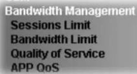
V-2-1 Sessions Limit
To configure Sessions Limit, from the Bandwidth Management menu, select Sessions Limit to open the setup page.
Bandwidth Management >> Sessions Limit
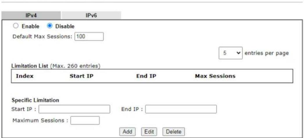



To activate the function of limit session, simply click Enable and set the default session limit. Available settings are explained as follows:
| Item | Description |
| Enable/Disable | Enable - Select to activate session limit function. Disable - Select to deactivate session limit function. Default Max Session - The default maximum number ofsessions allowed per LAN client, unless overridden by specifying a different number in the Limitation List. |
| Limitation List Displays specific limitation entries. | |
| Specific Limitation Start IP | - The beginning IP address for this limit entry.End IP - The ending IP address for limit entry.Max Sessions - The maximum number of NAT sessions allowed per LAN client. If no value is entered, the Default Max Sessions value is used.Add - Creates a new limit entry using the above Specific Limitation values.Edit - To edit an existing entry, select the entry from the Limitation List, make the appropriate changes in Specific Limitation, then click Edit.Delete - To delete an entry, select it from the Limitation List, then click the Delete button. |
| Administration Message Message to be displayed in a web browser on the LAN client when the maximum number of NAT sessions has been reached.Default Message - Click to reset the administration message to the factory default. | |
| Time Schedule Schedule Profile - Specify up to 4 time schedule entries to enable or disable the WAN. | |
To save changes on the page, click OK.
V-2-2 Bandwidth Limit
To configure the Bandwidth Limit feature, from the Bandwidth Management menu, select Bandwidth Limit to bring up the configuration page.
Bandwidth Management >> Bandwidth Limit
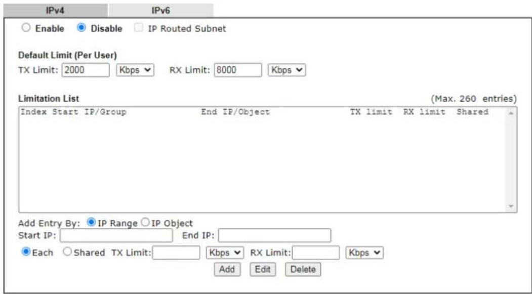
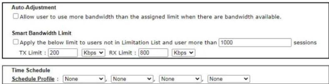
To activate the function of limit bandwidth, simply click Enable and set the default upstream and downstream limit.
Available settings are explained as follows:
| Item | Description |
| Enable / Disable Enable - Select to activate bandwidth limit function.Disable - Select to deactivate bandwidth limit function.IP Routed Subnet - Check this box to apply the bandwidth limit to the traffic via IP routed subnet.Default Limit (Per User)TX LImit - Default upstream speed limit for each LAN client. Unit can be either Kbps or Mbps. Value must be between 0 (unlimited) and 30000.RX limit - Default downstream speed limit for each LAN client. Unit can be either Kbps or Mbps. Value must be between 0 (unlimited and 30000). | |
| Limitation List Displays specific limitation entries. | |
| Add Entry By IP Range - All | the IPs within the range defined will be restricted by bandwidth limit defined by TX Limit and RXLimit below.● Start IP - The beginning IP address for this limit entry.● End IP - The ending IP address for limit entry.IP Object - All the IPs specified by the selected IP object or IP group will be restricted by bandwidth limit defined by TX Limit and RX Limit below.● IP Group - Specify an IP group by using the drop down list.● IP Object - Specify an IP object by using the drop down list.Each - The specified bandwidth is the limit per LAN client.Shared - The specified bandwidth limits are the total allowed for all LAN clients within the range of IP addresses.● TX limit - The upstream limit. Unit can be either Kbps or Mbps. Value must be between 0 (unlimited) and 30000.● RX limit - The downstream limit. Unit can be either Kbps or Mbps. Value must be between 0 (unlimited) and 30000.Add - Creates a new limit entry using the above Specific Limitation values.Edit - To edit an existing entry, select the entry from the Limitation List, make the appropriate changes in Specific Limitation, then click Edit.Delete - To delete an entry, select it from the Limitation List, then click the Delete button. |
| Auto-Adjustment | Allow user to use more bandwidth ...- Select to let the router automatically adjust the upstream and downstream limits based on available bandwidth. |
| Smart Bandwidth Limit This option restricts the bandwidth of LAN clients that are not in the limitation list when the network sessions exceed a predefined threshold.Apply the below limit to ... - The number of sessions a LAN client is allowed to have before Smart Bandwidth Limit activates.● TX limit - Upstream speed limit for each LAN client. Unit can be either Kbps or Mbps. Value must be between 0 (unlimited) and 30000.● RX limit - Downstream speed limit for each LAN client. Unit can be either Kbps or Mbps. Value must be between 0 (unlimited and 30000). | |
| Time Schedule Schedule Profile - Specify up to 4 time schedule entries to enable or disable the WAN. | |
V-2-3 Quality of Service
To configure Quality of Service, from the main menu, select Bandwidth Management menu, then click Quality of Service to bring up the configuration page.
Bandwidth Management >> Quality of Service
| Index Enable | Direction | Inbound/ Outbound Bandwidth | Class 1 | Class 2 | Class 3 | Others | Status | ||||||||
| WAN1 | BOTH | 100 | Mbps / | 100 | Mbps | 25 | % | 25 | % | 25 | % | 25 | % | Status | |
| WAN3 | BOTH | 100 | Mbps / | 100 | Mbps | 25 | % | 25 | % | 25 | % | 25 | % | Status | |
| WAN5 | BOTH | 100 | Mbps / | 100 | Mbps | 25 | % | 25 | % | 25 | % | 25 | % | Status | |
| WAN6 | BOTH | 100 | Mbps / | 100 | Mbps | 25 | % | 25 | % | 25 | % | 25 | % | Status | |
| WAN7 | BOTH | 100 | Mbps / | 100 | Mbps | 25 | % | 25 | % | 25 | % | 25 | % | Status | |
| WAN8 | BOTH | 100 | Mbps / | 100 | Mbps | 25 | % | 25 | % | 25 | % | 25 | % | Status | |
Note:
QoS may not work properly if the bandwidth entered is not correct. Before enable QoS, you may run speed test (from e.g., http://speedtest.net) or contact your ISP for the accurate bandwidth.
Class Rule
| Index | Enable | QoS Class | Local Address | Remote Address | DSCP | Service Type |
| Add |
Note:
-
The packets that don't match any class rules above will be classified into 'Others'
-
Go to User Defined Service Type to edit/delete user-defined service type profiles.
VoIP Prioritization
| Enable the First Priority for VoIP SIP/RTP: | |
| SIP UDP Port:5060 | (Default:5060) |
Tag Outbound Traffic
| Class 1 | Add DSCP or Precedence Value | Default | √ |
| Class 2 | Add DSCP or Precedence Value | Default | √ |
| Class 3 | Add DSCP or Precedence Value | Default | √ |

Available settings are explained as follows:
| Item | Description |
| General Setup Index - Link of WAN interface. | Enable - Check the box to enable the QoS function for WAN interface. If it is enabled, you can configure general QoS setting for each WAN interface.Direction -Direction of traffic to which QoS is to be applied (Inbound, Outbound, or Both).IN - Apply QoS to incoming traffic only.OUT - Apply QoS to outgoing traffic only.BOTH - Apply to both incoming and outgoing traffic.Inbound/Outbound Bandwidth -The inbound / outbound bandwidth of the WAN. This option is not available on ADSL/ VDSL WAN1 interface.Class 1 ~ 3 / Others - Percentage of bandwidth reserved for each class.Status - Click to bring up the Online Statistics page that shows snapshots of statistics for the given WAN interface. |
| Class Rule Define and list | the Class rules.Index - Displays the class number that you can edit.Enable - Displays the status of this class rule.QoS Class - Displays the QoS class level.Local Address - Displays the local IP address for the rule.Remote Address - Displays the remote IP address for the rule.DSCP - Displays the levels of the data for processing with QoS control.Service Type - Displays detailed settings for the service type.Add - Click it to create a class rule for QoS. |
| VoIP Prioritization | Enable the First Priority for VoIP SIP/RTP - Select to allow VoIP traffic to receive the highest priority.SIP UDP Port - Port number to be monitored for SIP traffic. |
| Tag Outbound Traffic | Tag the outgoing traffic with the DSCP or Precedence value.Add DSCP or Precedence Value for Class 1 to Class 3 - Check to apply the DSCP or precedence value for each class. |
To save changes, click OK; to discard changes, click Cancel.
Online Statistics
Click the Status link in the General Setup section to show real-time online statistics of the WAN interface.
Bandwidth Management >> Quality of Service
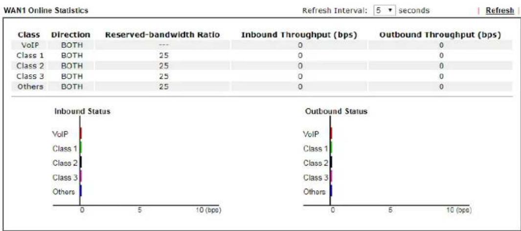
Cancel
General Setup for WAN Interface
Click WAN interface number link to configure the limited bandwidth ratio for QoS of the WAN interface.
Bandwidth Management >> Quality of Service >> WAN1
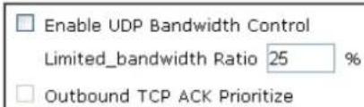

Available settings are explained as follows:
| Item | Description |
| Enable UDP Bandwidth Control | Select to restrict the bandwidth available to UDP traffic. The Limited_bandwidth Ratio value is the maximum percentage of bandwidth that can be used by UDP traffic.● Limited_bandwidth Ratio - Enter a percentage value. |
| Outbound TCP ACK Prioritize | Select to give outbound ACK packets priority over other packets to ensure traffic is not slowed down because the remote host is waiting for ACK packets before further traffic will be sent. |

Info
The rate of outbound/inbound must be smaller than the real bandwidth to ensure correct calculation of QoS. It is suggested to set the bandwidth value for inbound/outbound as 80% - 85% of physical network speed provided by ISP to maximize the QoS performance.
Add / edit the Class Rule for QoS
You can set up to 20 rules for one Class. If you want to edit an existed rule, please select the radio button of that one and click Edit to open the rule edit page for modification.
- To add a rule, click Add to bring up the configuration page. To edit an existing rule, select the rule by clicking the radio button in front of the rule, and then click Edit to bring up the configuration page.
Bandwidth Management >> Quality of Service
| Index Enable | Direction | Inbound/ Outbound Bandwidth | Class 1 | Class 2 | Class 3 | Others | Status | ||||||||
| WAN1 | BOTH | 100 | Mbps / | 100 | Mbps | 25 | % | 25 | % | 25 | % | 25 | % | Status | |
| WAN3 | BOTH | 100 | Mbps / | 100 | Mbps | 25 | % | 25 | % | 25 | % | 25 | % | Status | |
| WAN5 | BOTH | 100 | Mbps / | 100 | Mbps | 25 | % | 25 | % | 25 | % | 25 | % | Status | |
| WAN6 | BOTH | 100 | Mbps / | 100 | Mbps | 25 | % | 25 | % | 25 | % | 25 | % | Status | |
| WAN7 | BOTH | 100 | Mbps / | 100 | Mbps | 25 | % | 25 | % | 25 | % | 25 | % | Status | |
| WAN8 | BOTH | 100 | Mbps / | 100 | Mbps | 25 | % | 25 | % | 25 | % | 25 | % | Status | |
Note:
QoS may not work properly if the bandwidth entered is not correct. Before enable QoS, you may run speed test (from e.g., http://speedtest.net) or contact your ISP for the accurate bandwidth.
Class Rule
| Index | Enable | QoS Class | Local Address | Remote Address | DSCP | Service Type |
| Add |
Note:
-
The packets that don't match any class rules above will be classified into 'Others'
-
Go to User Defined Service Type to edit/delete user-defined service type profiles.
-
For adding a new rule, click Add to open the following page.
Bandwidth Management >> Quality of Service
Rule 1
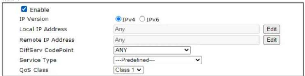

Available settings are explained as follows:
| Item | Description |
| Enable Select to enable this rule. | |
| IP Version Protocol (IPv4 or IPv6) to which this rule applies. | |
| Local IP Address | Click the Edit button to set the local (LAN) IP address or address range for the rule. |
| DiffServ CodePoint DSCP or ToS precedence of packets to which this rule applies. | |
| Remote IP Address | Click the Edit button to set the remote (WAN) IP address or address range for the rule.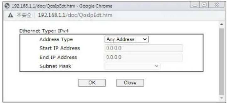 Address Type - Type of address: Any Address, Single Address, Range Address, Subnet Address.Single Address - Specify IP address.Range Address - Specify Start IP Address and End IP Address.Subnet Address - Specify Start IP Address and Subnet Mask. Address Type - Type of address: Any Address, Single Address, Range Address, Subnet Address.Single Address - Specify IP address.Range Address - Specify Start IP Address and End IP Address.Subnet Address - Specify Start IP Address and Subnet Mask. |
| Service Type Service Type | Service is a predefined or user-defined type of traffic that uses certain protocols or ports. To set up a custom service, select User Defined to set the service name, the protocol, and port number. |
| QoS Class Specify the QoS class (1, 2 or 3) for this rule. | |
- After finishing all the settings here, please click OK to save the configuration.
Bandwidth Management >> Quality of Service
| General Setup | Set to Factory Default | ||||||||||||
| Index | Enable | Direction | Inbound/ Outbound Bandwidth | Class 1 | Class 2 | Class 3 | Others | Status | |||||
| WAN1 | BOTH | 100 | Mbps / | 100 | Mbps | 25 | % | 25 | % | 25 | % | Status | |
| WAN3 | BOTH | 100 | Mbps / | 100 | Mbps | 25 | % | 25 | % | 25 | % | Status | |
| WAN5 | BOTH | 100 | Mbps / | 100 | Mbps | 25 | % | 25 | % | 25 | % | Status | |
| WAN6 | BOTH | 100 | Mbps / | 100 | Mbps | 25 | % | 25 | % | 25 | % | Status | |
| WAN7 | BOTH | 100 | Mbps / | 100 | Mbps | 25 | % | 25 | % | 25 | % | Status | |
| WAN8 | BOTH | 100 | Mbps / | 100 | Mbps | 25 | % | 25 | % | 25 | % | Status | |
Note:
QoS may not work properly if the bandwidth entered is not correct. Before enable QoS, you may run speed test (from e.g., http://speedtest.net) or contact your ISP for the accurate bandwidth.
Class Rule
| Index | Enable | QoS Class | Local Address | Remote Address | DSCP | Service Type |
| 1 | Class1 | Any | Any | ANY | ANY | |
| Add |
Note:
1. The packets that don't match any class rules above will be classified into 'Others'
2. Go to User Defined Service Type to edit/delete user-defined service type profiles.
Retag the Packets for Identification
Packets originating from the LAN that are destined for the WAN can have the DS flag changed to a different value by enabling Tag Packet and specifying the DSCP or IP Precedence value.
In the following illustration, outbound VoIP packets from the LAN arrive at the Vigor router with the QoS value unset. The router sets the DSCP value to AF before forwarding them to the ISP server via the WAN interface.
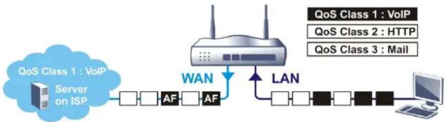
flowchart
graph LR
    A["QoS Class 1 : VoIP Server on ISP"] --> B["Router"]
    B --> C["WAN"]
    C --> D["LAN"]
    D --> E["Computer"]
    style A fill:#cce5ff,stroke:#333
    style B fill:#e6f3ff,stroke:#333
    style C fill:#fff2cc,stroke:#333
    style D fill:#fff2cc,stroke:#333
    style E fill:#fff2cc,stroke:#333
Class Rule
| Index | Enable | Qos Class | Local Address | Remote Address | DSCP | Service Type |
| 1 | √ | Class 1 | Any | Any | ANY | SIP(UDP:5060) |
| 2 | √ | Class 2 | Any | Any | ANY | HTTP(TCP:80) |
| 3 | √ | Class 3 | Any | Any | ANY | SMTP(TCP:25) |
Note:
The packets that don't match any class rules above will be classified into 'Others'
VoIP Prioritization
| Enable the First Priority for VoIP SIP/RTP: | ||
| SIP UDP Port: 5060 (Default:5060) | ||
| Tag Outbound Traffic | ||
| Class 1 | Add DSCP or Precedence Value | Default |
| Class 2 | Add DSCP or Precedence Value | Default |
| Class 3 | Add DSCP or Precedence Value | Default |
V-2-4 APP QoS
To configure APP QoS, from the main menu, select Bandwidth Management menu, then click APP QoS to bring up the configuration page.
Bandwidth Management >> APP QoS
APP QoS
| Enable | Instant Message | Version | Action |
| □ | Facebook/Instagram | QoS Class 1 (High) ▼ | |
| □ | LINE | 5.23.0.2134 | QoS Class 1 (High) ▼ |
| □ | QoS Class 1 (High) ▼ | ||
| □ | Signal | 1.26.2 | QoS Class 1 (High) ▼ |
| □ | Slack | 4.0.0 | QoS Class 1 (High) ▼ |
| □ | Snapchat | 10.79.5.0 | QoS Class 1 (High) ▼ |
| □ | Telegram | 1.7.10 | QoS Class 1 (High) ▼ |
| □ | 0.3.2848 | QoS Class 1 (High) ▼ | |
| Enable | VoIP | Version | Action |
| □ | Skype | 8.51.0.86 | QoS Class 1 (High) ▼ |
Available settings are explained as follows:
| Item | Description |
| Enable/Disable Enables or | disables the APP QoS feature. |
| Traceable Traceable applications are those whose traffic can be 100% traced.All protocols under this tab can have a specific QoS class assigned.Enable - Select to enable QoS for the application.Apply to all - Select a QoS class to be applied to all protocols. You can override the QoS class for specific protocols using the Action dropdown listbox. | |
| Untraceable Untraceable applications are detected when they attempt to establish connections to remote hosts, and all traffic between the remote hosts and the local network will be placed under QoS, within the same QoS class.All protocols under this tab can have a specific QoS class assigned.Enable - Select to enable QoS for the application.Action - Select a QoS class to be applied to all applications. | |
| Select All Click to select all | Enabled checkboxes. |
| Clear All Click to deselect all | Enabled checkboxes. |
After changes have been made, click OK to save changes, or Cancel to discard.
V-3 User Management
User Management is a security feature which disallows any IP traffic (except DHCP-related packets) from a particular host until that host has correctly supplied a valid username and password. Instead of managing with IP address/MAC address, User Management function manages hosts with user account. Network administrator can give different firewall policies or rules for different hosts with different User Management accounts. This is more flexible and convenient for network management. Not only offering the basic checking for Internet access, User Management also provides additional firewall rules, e.g. CSM checking for protecting hosts.
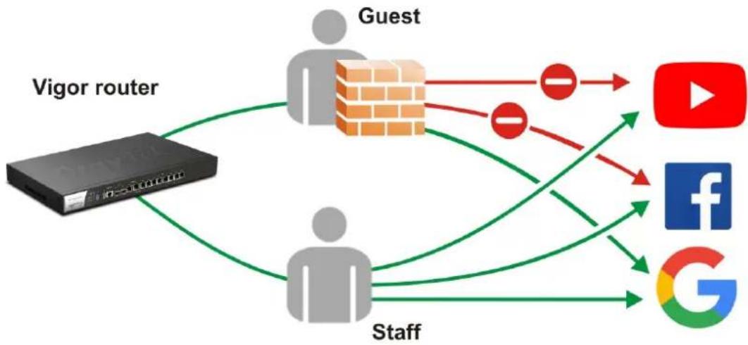
flowchart
graph TD
    A["Vigor router"] --> B["Guest"]
    B --> C["YouTube"]
    B --> D["Facebook"]
    B --> E["Google"]
    A --> F["Staff"]
    F --> B
    B --> G["Social Media Platform"]

Info
Filter rules configured under Firewall usually are applied to the host (the one that the router installed) only. With user management, the rules can be applied to every user connected to the router with customized profiles.
Web User Interface
电话:057911
User Management
General Setup
User Profile
User Group
User Online Status
PPPoE User Online Status
V-3-1 General Setup
General Setup can determine the standard (rule-based or user-based) for the users controlled by User Management. The mode (standard) selected here will influence the contents of the filter rule(s) applied to every user.
User Management >> General Setup
General Setup
Mode Selection:
Rule-Based is a management method based on IP address. Administrator may set different firewall rules to different IP address.
○ User-Based is a management method based on user profiles. Administrator may set different firewall rules to different user profiles.
Authentication page:
Web Authentication:

HTTPS

HTTP
Login Page Greeting
□ Display IP address on the dialog box pops up after successful login.
Landing page:
(Max 255 characters)
Preview| Set to Factory Default
OK
Clear
Cancel
Available settings are explained as follows:
| Item | Description |
| Mode Selection There are t | two modes offered here for you to choose. Each mode will bring different filtering effect to the users involved.User-Based- If you choose such mode, the router will apply the filter rules configured inUser Management>>User Profileto the users.Rule-Based-If you choose such mode, the router will apply the filter rules configured inFirewall>>General SetupandFilter Rule to the users. |
| Authentication page | Web Authentication - Choose the protocol for web authentication.Login Page Greeting- Such link allows you to access into the setting page for login greeting. For detailed information, refer to System Maintenance>>Login Page Greeting.Display IP Address on ... - Check the box to display the IP address of the client on the tracking window. |
| Landing Page Type the information to be displayed on the first web page when the LAN user accessing into Internet via such router. | |
After finishing all the settings here, please click OK to save the configuration.
V-3-2 User Profile
This page allows you to set customized profiles (up to 200) which will be applied for users controlled under User Management. Simply open User Management>>User Profile.
User Management >> User Profile
| User Profile Table | | Set to Factory Default | | |||||
| Select All | Clear All | Search | ||||
| Profile | Enable | Name | Profile | Enable | Name | |
| 1. | admin | 17. | ||||
| 2. | Dial-In User | 18. | ||||
| 3. | james | 19. | ||||
| 4. | 20. | |||||
| 5. | 21. | |||||
| 6. | 22. | |||||
| 7. | 23. | |||||
| 8. | 24. | |||||
| 9. | 25. | |||||
| 10. | 26. | |||||
| 11. | 27. | |||||
| 12. | 28. | |||||
| 13. | 29. | |||||
| 14. | 30. | |||||
| 15. | 31. | |||||
| 16. | 32. | |||||
Note:
- admin: To change the administrator password, please go to System Maintenance >> Administrator Password.
- Dial-In User Profile: Dial-In User Profile is reserved for VPN authentication.
- During authentication, Router will check all the local user profiles first, and then the profiles in external servers.

To set the user profile, please click any index number link to open the following page. Notice that profile 1 (admin) and profile 2 (Dial-In User) are factory default settings. Profile 2 is reserved for future use.
Profile Index 3
Common Settings

Login Settings User Online Status : Block/ Unblock
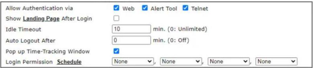
Policy
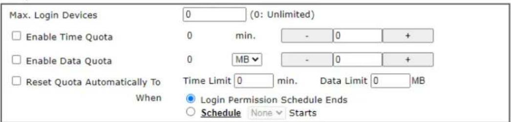
PPPoE Login Settings PPPoE User Online Status Reset User Online Status

Other Services


Available settings are explained as follows:
| Item | Description |
| Common Settings Enable this account - Check this box to enable such user profile.Username - Type a name for such user profile (e.g., LAN_User_Group_1, WLAN_User_Group_A, WLAN_User_Group_B, etc). When a user tries to access Internet through this router, an authentication step must be performed first. The user has to type the User Name specified here to pass the authentication. When the user passes the authentication, he/she can access Internet via this router. However the accessing operation will be restricted with the conditions configured in this user profile.The maximum length of the name you can set is 24 | |
| characters.Password - Type a password for such profile (e.g., lug123, wug123, wug456, etc). When a user tries to access Internet through this router, an authentication step must be performed first. The user has to type the password specified here to pass the authentication. When the user passes the authentication, he/she can access Internet via this router with the limitation configured in this user profile.The maximum length of the password you can set is 24 characters.Confirm Password - Type the password again for confirmation.External Service Authentication - The router will authenticate the dial-in user by itself or by external service such as LDAP server or RADIUS server or TACACS+ server. If LDAP, Radius or TACACS+ is selected here, it is not necessary to configure the password setting above. | |
| Login Settings | Allow Authentication via- Any user (from LAN side or WLAN side) tries to connect to Internet via Vigor router must be authenticated by the router first. There are three ways offered by the router for the user to choose for authentication.Web - If it is selected, the user can type the URL of the router from any browser. Then, a login window will be popped up and ask the user to type the user name and password for authentication. If succeed, a Welcome Message (configured in User Management >> General Setup) will be displayed. After authentication, the destination URL (if requested by the user) will be guided automatically by the router.Alert Tool - If it is selected, the user can open Alert Tool and type the user name and password for authentication. A window with remaining time of connection for such user will be displayed. Next, the user can access Internet through any browser on Windows. Note that Alert Tool can be downloaded from DrayTek web site.Telnet - If it is selected, the user can use Telnet command to perform the authentication job.Show Landing Page After Login - When a user tries to access into the web user interface of Vigor router series with the user name and password specified in this profile, he/she will be lead into the web page configured in Landing Page field in User Management>>General Setup. Check this box to enable such function.Idle Timeout - If the user is idle over the limitation of the timer, the network connection will be stopped for such user. By default, the Idle Timeout is set to 10 minutes.Auto Logout After - Such account will be forced to logout after a certain time set here.Pop up Time-Tracking Window - If such function is enabled, a pop up window will be displayed on the screen with time remaining for connection if Idle Timeout is set. However, the system will update the time periodically to keep the connection always on. Thus, Idle Timeout will not interrupt the network connection.Login Permission Schedule - You can type in four sets of time schedule for your request. All the schedules can be setpreviously inApplication >>Scheduleweb page and you can use the number that you have set in that web page. |
Policy Max Login Devices - Such profile can be used by many users.You can set the limitation for the number of users accessing Internet with the conditions of such profile. The default setting is 0 which means no limitation in the number of users.Enable Time Quota- Time quota means the total connection time allowed by the router for the user with such profile. Check the box to enable the function of time quota. The first box displays the remaining time of the network connection. The second box allows to type the number of time (unit is minute) which is available for the user (using such profile) to access Internet.+ - Click this box to set and increase the time quota for such profile.- - Click this box to decrease the time quota for such profile.Note:A dialog will be popped up to notify how many time remained when a user accesses into Internet through Vigor router successfully.When the time is up, all the connection jobs including network, IM, social media, facebook, and etc. will be terminated.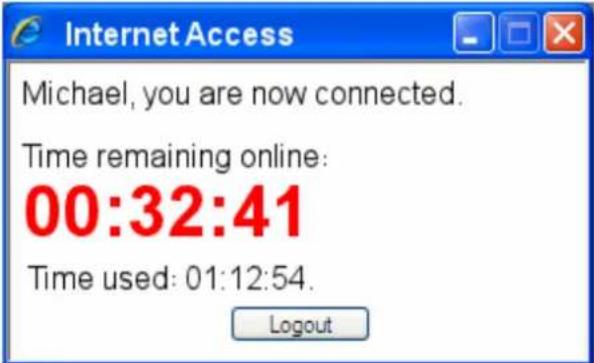 Enable Data Quota- Data Quota means the total amount for data transmission allowed for the user. The unit is MB/ GB.+ - Click this box to set and increase the data quota for such profile.- - Click this box to decrease the data quota for such profile.Reset Quota Automatically To- Set default time quota and data quota for such profile. When the scheduling time is up, the router will use the default quota settings automatically. Check it to use the default setting for time quota and data quota.Time Limit- Type the value for the time manually.Data Limit- Type the value for the data manually.Login Permission Schedule Ends- When the scheduling time is up, the router will reset the quota with user-defined time/ data values automatically.Schedule- The router will reset the quota with user-defined time/ data values at the starting time configured in the Enable Data Quota- Data Quota means the total amount for data transmission allowed for the user. The unit is MB/ GB.+ - Click this box to set and increase the data quota for such profile.- - Click this box to decrease the data quota for such profile.Reset Quota Automatically To- Set default time quota and data quota for such profile. When the scheduling time is up, the router will use the default quota settings automatically. Check it to use the default setting for time quota and data quota.Time Limit- Type the value for the time manually.Data Limit- Type the value for the data manually.Login Permission Schedule Ends- When the scheduling time is up, the router will reset the quota with user-defined time/ data values automatically.Schedule- The router will reset the quota with user-defined time/ data values at the starting time configured in the | selected schedule profile. |
| PPPoE Login Setting Such user account will be used (1) by the client with the IP address specified or (2) by the client with the MAC address bound with the IP address, for accessing into Vigor3910 web user interface.PPPoE MAC Bind - Specify a MAC address which is limited and used for such PPPoE account.Enable/Disable - Click it to enable/ disable the function of PPPoE MAC Bind.MAC Address - Type the MAC address to be bound with the IP address set below if PPPoE MAC Bind is enabled.DHCP From - Use the drop down list to specify LAN/ DMZ interface. The IP address for binding with the MAC address (above) set in the selected interface will be assigned from the IP address set in the selected interface.Static IP Address (optional)- Type an IP address. | |
| Other Services Allow this profile to be used by - This option is available for profiles with index number 3 to 200.Internal RADIUS- Check the box to enable security authenticated via internal RADIUS server.Local 802.1X - Check the box to enable security authenticated via internal 802.1X server.Log - Activities of the user can be recorded by Syslog.None - Logging is disabled.Login - Login and logout activities are logged.Event - Allowed and blocked traffic are logged.All - Both Login and Event types are logged. | |
After finishing all the settings here, please click OK to save the configuration.
V-3-3 User Group
This page allows you to bind several user profiles into one group. These groups will be used in Firewall>>General Setup as part of filter rules.
User Management >> User Group
Please click any index number link to open the following page.
User Management >> User Group
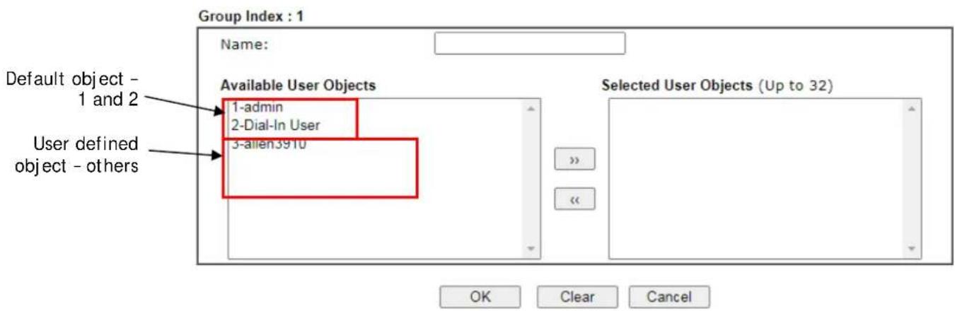
Available settings are explained as follows:
| Item | Description |
| Name Type a name for this user group. | |
| Available User Objects | You can gather user profiles (objects) fromUser Profilepage within one user group. All the available user objects that you have created will be shown in this box. Notice that user object, Admin and Dial-In User are factory settings. User defined profiles will be numbered with 3, 4, 5 and so on. |
| Selected Keyword Objects | Click >> button to add the selected user objects in this box. |
After finishing all the settings here, please click OK to save the configuration.
V-3-4 User Online Status
This page displays the user(s) connected to the router and refreshes the connection status in an interval of several seconds.
User Management >> User Online Status

Note:
- Please click "IP Address" to view all online users.
- Dial-in User profiles are linked to VPN clients and therefore cannot be logged-out or deleted while connecting.
- Information about 802.1X authentication can be found at Authentication User List.
Total Number : 1
Available settings are explained as follows:
| Item | Description |
| Refresh Seconds Use the drop down list to choose the time interval of refreshing data flow that will be done by the system automatically. | |
| Refresh Click this link to refresh this page manually. | |
| Index Display the number of the data flow. | |
| User | Display the users which connect to Vigor router currently. You can click the link under the username to open the user profile setting page for that user. |
| IP Address Display the IP address of the device. | |
| Profile Display the authority of the account. | |
| Last Login Time Display the login time that such user connects to the router last time. | |
| Expired Time Display the expired time of the network connection for the user. | |
| Data Quota Display the quota for data transmission. | |
| Idle Time Display the idle timeout setting for such profile. | |
| Action | Block - can avoid specified user accessing into Internet. Unblock - allow the user to access into Internet. Logout - the user will be logged out forcefully. |
V-3-5 PPPoE User Online Status
PPPoE User Online Status displays connection information (including IP address, MAC address, user name, transmitted bytes, received bytes, up time and so on) for the LAN client who accesses Internet via the built-in PPPoE server of Vigor router.
User Management >> PPPoE User Online Status
| Index | IP Address | MAC Address | User Name | Rx Bytes | Tx Bytes | Up Time |
Total Number: 0
Available settings are explained as follows:
| Item | Description |
| Refresh Seconds Use the drop down list to choose the time interval of refreshing data flow that will be done by the system automatically. | |
| Refresh Click this link to refresh this page manually. | |
| IP Address Displays the IP address of the client in LAN. | |
| MAC Address Displays the MAC address of the client in LAN. | |
| User Name | Displays the name of user connecting to Vigor router currently. You can click the link under the username to open the user profile setting page for that user. |
| Rx Bytes Displays the speed of octets received through such PPPoE user. | |
| Tx Bytes Displays the speed of octets transmitted through such PPPoE user. | |
| Up Time Displays the connection time of such PPPoE user. | |
Application Notes
A-1 How to authenticate clients via User Management
Before using the function of User Management, please make sure User-Based has been selected as the Mode in the User Management>>General Setup page.
User Management >> General Setup
General Setup
Mode Selection:
○ Rule-Based is a management method based on IP address. Administrator may set different firewall rules to different IP address.
User-Based is a management method based on user profiles. Administrator may set different firewall rules to different user profiles.
Notice for User-Based mode:
- In User-Based mode, Active Rules in Firewall will be applied to all LAN clients, packets that matches the Active Rules will be blocked or pass immediately, no user authentication is required.
- Only Inactive Rules in Firewall can be set for individual user profile. In User-Based
With User Management authentication function, before a valid username and password have been correctly supplied, a particular client will not be allowed to access Internet through the router. There are three ways for authentication: Web, Alert Tool and Telnet.
User Management >>User Profile
Profile Index 3
Common Settings
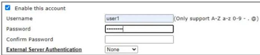
![Login Settings Allow Authentication via ✓ Web ✓ Alert Tool ✓ Telnet Show Landing Page After Login [] Idle Timeout 10 min. (0: Unlimited) Auto Logout After 0 min. (0: Off)](/content/2026/05/813922/images/6e93ea5a493950ae87f47340c68922f80fe7b57abf697de428614f040e817ffd.jpg)
Authentication via Web
If a LAN client who hasn't passed the authentication opens an external web site in his browser, he will be redirected to the router's Web authentication interface first. Then, the client is trying to access http://www.draytek.com and but brought to the Vigor router. Since this is an SSL connection, some web browsers will display warning messages.
- With Microsoft Internet Explorer, you may get the following warning message. Please press Continue to this website (not recommended).
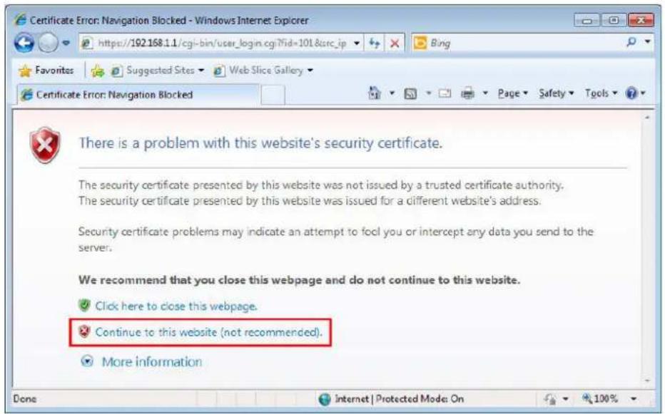
- With Mozilla Firefox, you may get the following warning message. Select I Understand the Risks.
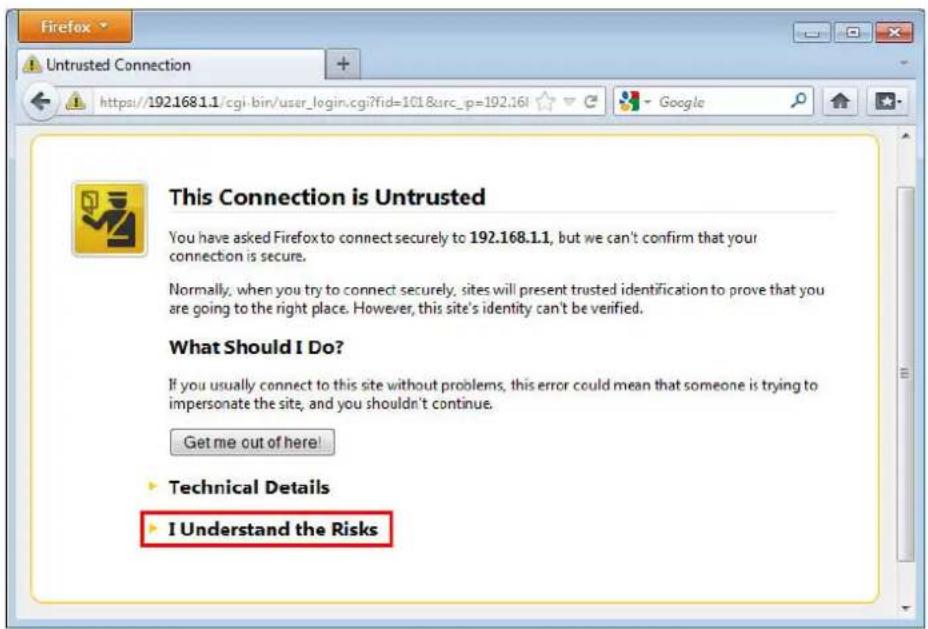
- With Chrome browser, you may get the following warning. Click Proceed anyway.
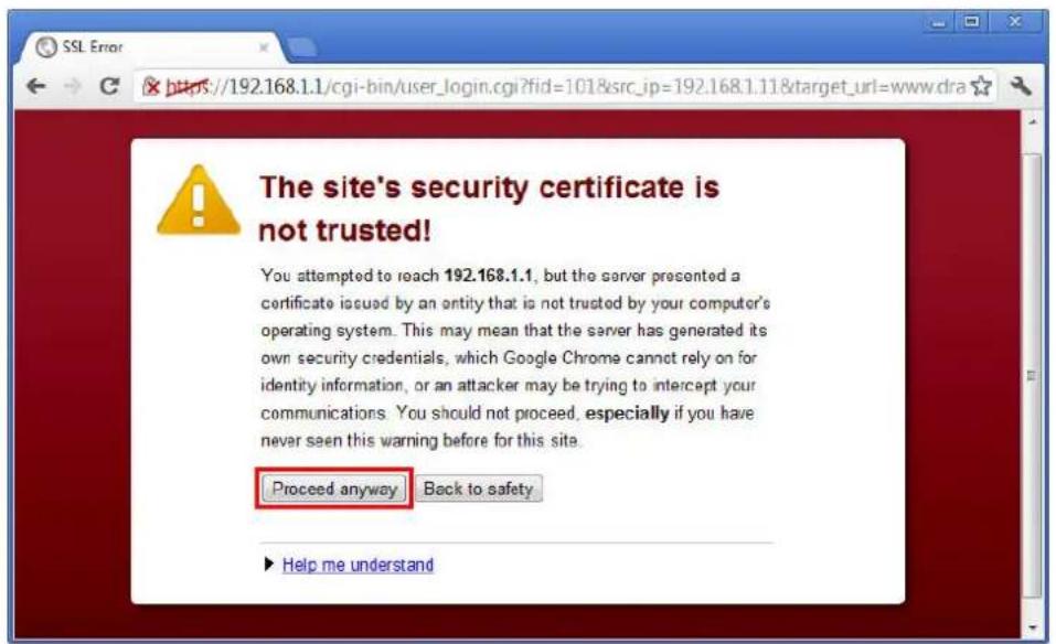
After that, the web authentication window will appear. Input the user name and the password for your account (defined in User Management) and click Login.
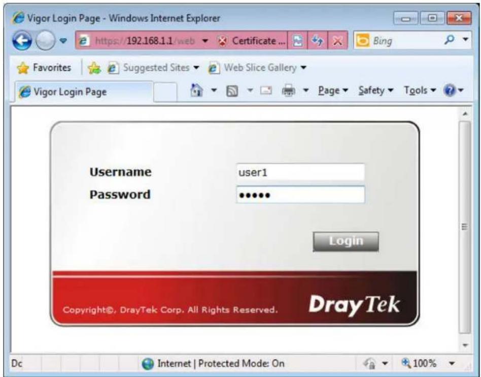
If the authentication is successful, the client will be redirected to the original web site that he tried to access. In this example, it is http://www.draytek.com . Furthermore, you will get a popped up window as the following. Then you can access the Internet.
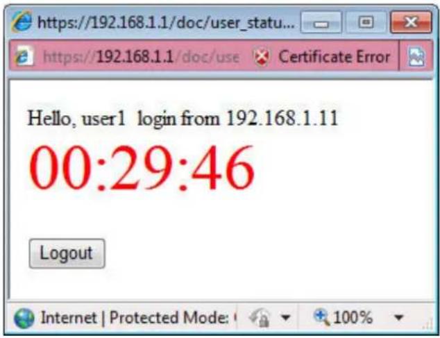
Note, if you block the web browser to pop up any window, you will not see such window.
If the authentication is failed, you will get the error message, The username or password you entered is incorrect. Please login again.
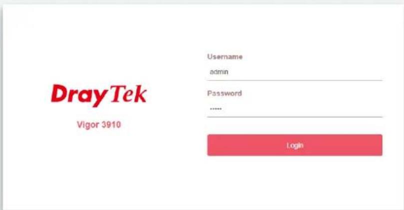
Copyright © 2000-2019DrayTel Corp. All Rights Reserved
In above description, you access an external web site to trigger the authentication. You may also directly access the router's Web UI for authentication. Both HTTP and HTTPS are supported, for example http://192.168.1.1 or https://192.168.1.1. Replace 192.168.1.1 with your router's real IP address, and add the port number if the default management port has been modified.
If the authentication is successful, you will get the Welcome Message that is set in the User Management >> General Setup page.
General Setup
Mode Selection:
○ Rule-Based is a management method based on IP address. Administrator may set different firewall rules to different IP address.
User-Based is a management method based on user profiles. Administrator may set different firewall rules to different user profiles.
Notice for User-Based mode:
- In User-Based mode, Active Rules in Firewall will be applied to all LAN clients, packets that matches the Active Rules will be blocked or pass immediately, no user authentication is required.
- Only Inactive Rules in Firewall can be set for individual user profile. In User-Based mode, packets that do not match Active Rules will need authentication, and the Inactive Rule applied to the specific user profile will then take effect.
Authentication page:
Web Authentication:

HTTPS

HTTP
With the default setup
- Vigor3910 Series Multi-WAN Security Router
- Copyrights
- Trademarks
- Safety Instructions
- Warranty
- Table of Contents
- Part I Installation....1
- Part II Connectivity ....63
- Part III VPN 215
- Part IV Security 275
- Part V Management ....327
- Application Notes 430
- V-5 Central Management (AP) 446
- V-6 Central Management (Switch) 460
- V-7 Central Management (External Devices).... 477
- Part VI Others....479
- Part VII Troubleshooting ....521
- Part VIII DrayTek Tools ....561
- Part IX Telnet Commands....567
- Part I Installation
- I-1 Introduction
- I-1-1 Indicators and Connectors
- I-2 Hardware Installation
- I-2-1 Installing Vigor Router
- I-2-2 Rack-Mounted Installation
- Desktop Type Installation
- I-3 Accessing Web Page
- Info
- I-4 Changing Password
- I-5 Dashboard
- I-5-1 Virtual Panel
- I-5-2 Quick Access for Common Used Menu
- I-5-3 GUI Map
- I-5-4 Web Console
- I-5-5 Config Backup
- I-5-6 Manual Download
- I-5-7 Logout
- I-5-8 Online Status
- I-5-8-1 Physical Connection
- Physical Connection for IPv4 Protocol
- Physical Connection for IPv6 Protocol
- I-5-8-2 Virtual WAN
- I-6 Quick Start Wizard
- Enter login password
- Quick Start Wizard
- WAN Interface
- I-6-1 For WAN1 (Fiber)
- Ethernet WAN1 - PPPoE
- Quick Start Wizard Setup OK!
- Ethernet WAN1 - Static IP
- Ethernet WAN1 - DHCP
- I-6-2 For WAN3 (Ethernet - 2.5G)
- Ethernet WAN3 - PPPoE
- Ethernet WAN3 - Static IP
- Wireless WAN3 - DHCP
- I-6-3 For WAN5\~WAN8 (Etherent)
- Ethernet WAN5 - PPPoE
- Connect to Internet
- PPPoE Client Mode
- Ethernet WAN5 - Static IP
- Wireless WAN5 - DHCP
- I-7 Service Activation Wizard
- I-8 Registering Vigor Router
- I-9 VPN Client Wizard
- Security Ranking:
- Very High
- High
- Medium
- Low
- Throughput Ranking:
- Note:
- VPN Client Wizard
- VPN Client L2TP Settings
- VPN Client L2TP over IPsec (Nice to Have) Settings
- I-10 VPN Server Wizard
- 192.168.1.1
- VPN Server Wizard
- VPN Authentication Setting
- Part II Connectivity
- II-1 Port Setup
- Web User Interface
- II-2-1 General Setup
- WAN 3
- II-2-2 Internet Access
- II-2-2-1 Details Page for PPPoE
- II-2-2-2 Details Page for Static or Dynamic IP
- II-2-2-3 Details Page for IPv6 – Offline in Ethernet WAN
- II-2-2-4 Details Page for IPv6 – PPP
- II-2-2-5 Details Page for IPv6 – TSPC
- II-2-2-6 Details Page for IPv6 – AICCU
- II-2-2-7 Details Page for IPv6 – DHCPv6 Client
- II-2-2-8 Details Page for IPv6 – Static IPv6
- II-2-2-9 Details Page for IPv6 – 6in4 Static Tunnel
- II-2-2-10 Details Page for IPv6 – 6rd
- II-2-3 Multi-VLAN
- II-2-4 WAN Budget
- II-2-4-1 General Setup
- Use Cycle in hours -
- Monthly
- Custom
- Use Cycle in days -
- II-2-4-2 Status
- II-3 LAN
- IP Address
- LAN
- II-3-1 General Setup
- II-3-1-1 Details Page for LAN1 – Ethernet TCP/IP and DHCP Setup
- II-3-1-2 Details Page for IP Routed Subnet
- TCP/IP and DHCP Setup for IP Routed Subnet
- II-3-1-3 Details Page for LAN1 – IPv6 Setup
- II-3-1-4 DHCP Server Option
- II-3-2 VLAN
- Inter-LAN Routing
- II-3-3 Bind IP to MAC
- Bind IP to MAC
- II-3-4 Port Mirror/Packet Capture
- II-3-5 Wired 802.1x
- II-3-6 PPPoE Server
- II-4 NAT
- II-4-1 Port Redirection
- II-4-2 DMZ Host
- II-4-3 Open Ports
- II-4-4 Port Triggering
- No. 1
- II-4-5 Fast NAT
- Usage:
- II-4-6 ALG
- II-5 Applications
- Dynamic DNS
- LAN DNS / DNS Forwarding
- Schedule
- RADIUS/TACACS+
- LDAP /Active Directory Setup
- UPnP
- Wake on LAN
- II-5-1 Dynamic DNS
- Index : 1
- DrayDDNS Settings
- DDNS updates take place when:
- Procedures for Setting up a Dynamic DNS Entry
- II-5-2 LAN DNS / DNS Forwarding
- II-5-3 DNS Security
- II-5-3-1 General Setup
- II-5-3-2 Domain Diagnose
- II-5-4 Schedule
- Example
- II-5-5 RADIUS/TACACS+
- II-5-5-1 External RADIUS
- Primary Server
- Secondary Server
- II-5-5-2 Internal RADIUS
- II-5-5-3 External TACACS+
- II-5-6 Active Directory/ LDAP
- II-5-6-1 General Setup
- II-5-6-2 Active Directory / LDAP Profiles
- II-5-7 UPnP
- Can't work with Firewall Software
- Security Considerations
- II-5-8 IGMP
- II-5-8-1 General Setting
- II-5-8-2 Working Status
- II-5-9 Wake on LAN
- II-5-10 SMS / Mail Alert Service
- II-5-10-1 SMS Alert
- II-5-10-2 Mail Alert
- II-5-11 Bonjour
- DNSSD for Firefox
- II-5-12 High Availability
- II-5-12-1 General Setup
- II-5-12-2 Config Sync
- Example:
- II-5-13 Local 802.1X General Setup
- II-5-14 Smart Action
- Application Notes
- Index No. 1
- and
- Index No. 2
- General Setup
- Mode Selection:
- Authentication page:
- Login Page Greeting
- PPP General Setup
- A-2 How to use DrayDDNS?
- DrayTek Service Activation
- Modify DrayDDNS Domain Name
- Device Information
- II-6 Routing
- Load Balance
- Specify Interface
- Address Mapping
- Priority
- Failover to/Failback
- Other routing
- Routing
- II-6-1 Static Route
- II-6-2 Load-Balance /Route Policy
- II-6-2-1 General Setup
- II-6-2-2 Diagnose for Route Policy
- Test how the packets will be routed
- Analysis
- Input File
- II-6-3 Fast Routing
- II-6-4 OSPF
- II-6-5 BGP
- II-6-4-1 Basic Settings
- II-6-4-2 Static Network
- Example 1:
- Example 2:
- Part III VPN
- III-1 VPN and Remote Access
- VPN and Remote Access
- III-1-1 Remote Access Control
- III-1-1-1 Remote Access Control Setup
- III-1-2 Bind to WAN
- III-1-2 PPP General Setup
- III-1-3 SSL General Setup
- III-1-4 IPsec General Setup
- VPN IKE/IPsec General Setup
- III-1-5 IPsec Peer Identity
- III-1-6 VPN Matcher Setup
- III-1-7 OpenVPN
- III-1-7-1 OpenVPN Server Setup
- III-1-7-2 Client Config
- III-1-7-3 Import Certificate
- III-1-8 WireGuard
- III-1-9 Remote Dial-in User
- III-1-10 LAN to LAN
- III-1-11 VPN Trunk Management
- III-1-12 Connection Management
- Configuration on Vigor Router for Branch Office
- Dial-Out Settings
- III-2 Certificate Management
- Certificate Management
- III-2-1 Local Certificate
- GENERATE
- IMPORT
- Import X509 Local Certificate
- Upload Local Certificate
- Upload PKCS12 Certificate
- Upload Certificate and Private Key
- Congratulation!
- III-2-2 Trusted CA Certificate
- Creating a RootCA
- III-2-3 Certificate Backup
- III-2-4 Self-Signed Certificate
- Part IV Security
- IV-1 Firewall
- Basic
- Firewall Facilities
- Data Filter
- Stateful Packet Inspection (SPI)
- Denial of Service (DoS) Defense
- IV-1-1 General Setup
- Default Rule Page
- IV-1-2 Filter Setup
- Strict Security Checking
- IV-1-3 Defense Setup
- IV-1-3 -1 DoS Defense
- IV-1-3-2 Spoofing Defense
- IV-1-4 Diagnose
- A-1 How to Configure Certain Computers Accessing to Internet
- IV-2 CSM (Central Security Management)
- CSM
- IV-2-1 APP Enforcement Profile
- IV-2-2 URL Content Filter Profile
- Administration Message (Max 255 characters)
- Default Message
- IV-2-3 Web Content Filter Profile
- Info 1
- Web-Filter License
- Web Content Filter Profile Table:
- Legend:
- IV-2-4 DNS Filter Profile
- A-1 How to Create an Account for MyVigor
- Terms of Service / Privacy Policy
- Agreement
- Registration
- About Us
- A-2 How to Block Facebook Service Accessed by the Users via Web Content Filter / URL Content Filter
- Web Content Filter,
- URL Content Filter,
- Via Web Content Filter
- Disallow users to play games on Facebook
- A-3 How to use APP Enforcement to block application like Facebook, YouTube or TeamViewer?
- Create an APP Enforcement Profile: Click on an Index number to create a new profile at CSM >> APP Enforcement Profile.
- Part V Management
- V-1 System Maintenance
- System Maintenance
- V-1-1 System Status
- V-1-2 TR-069
- V-1-2-1 ACS and CPE Settings
- V-1-2-2 Reporting Configuration
- V-1-2-3 Export Parameters
- V-1-3 Administrator Password
- V-1-4 User Password
- V-1-5 Login Page Greeting
- Welcome Message
- DrayTek
- V-1-6 Configuration Backup
- Backing up the Configuration
- Restoring the Configuration
- V-1-7 Configuration Export
- V-1-8 Webhook
- Note
- V-1-9 Syslog/Mail Alert
- SysLog / Mail Alert Setup
- SysLog Access Setup
- Primary Syslog Server
- Secondary Syslog Server
- Mail Alert Setup
- V-1-10 Time and Date
- V-1-11 SNMP
- SNMP Setup
- V-1-12 Management
- V-1-12-2 IPv6 Management Setup
- V-1-12-3 LAN Access Control
- V-1-13 Self-Signed Certificate
- V-1-14 Reboot System
- V-1-15 Firmware Upgrade
- V-1-16 Internal Service User List
- V-1-17 Dashboard Control
- V-1-18 Max Connection
- V-2 Bandwidth Management
- Sessions Limit
- Bandwidth Limit
- Quality of Service (QoS)
- APP QoS
- V-2-1 Sessions Limit
- V-2-2 Bandwidth Limit
- V-2-3 Quality of Service
- Online Statistics
- V-2-4 APP QoS
- V-3 User Management
- User Management
- V-3-1 General Setup
- Landing page:
- V-3-2 User Profile
- Profile Index 3
- Common Settings
- Login Settings User Online Status : Block/ Unblock
- Policy
- PPPoE Login Settings PPPoE User Online Status Reset User Online Status
- Other Services
- V-3-3 User Group
- V-3-4 User Online Status
- V-3-5 PPPoE User Online Status
- A-1 How to authenticate clients via User Management
- Notice for User-Based mode:
- Authentication via Web
- VPN and Remote Access >> Remote Dial-in User
- Authentication via Telnet
- Authentication via VigorPro Alert Notice Tool
- A-2 How to use Landing Page Feature
- V-4 Hotspot Web Portal
- Hotspot Web Portal
- V-4-1 Profile Setup
- V-4-1-1 Login Method
- V-4-1-2 Steps for Configuring a Web Portal Profile
- Login Method
- Portal Server
- Login Methods
- Background
- Login Page Setup
- Click Through
- Various Hotspot Login
- 2nd-stage Page for PIN Login
- Whitelist Setting
- More Options
- V-4-2 Users Information
- V-4-2-1 User Info
- User Table
- V-4-2-2 Database Setup
- Notification and Action when Storage Exceeded
- Advanced options
- V-4-3 Quota Management
- V-4-4 PIN Generator
- V-4-4-1 RN Status
- V-4-4-2 RN Generator
- V-4-4-3 RN Voucher
- Enter the values as the following figure.
- Hotspot Clients Login
- User Information
- A-2 How to allow hotspot clients to get login PIN code via SMS?
- Vigor Router Setup
- Hotspot Client Login
- V-5 Central Management (AP)
- V-5-1 Dashboard
- V-5-2 Status
- V-5-3 WLAN Profile
- V-5-4 AP Maintenance
- V-5-5 Traffic Graph
- V-5-6 Event Log
- V-5-7 Total Traffic
- V-5-8 Station Number
- V-5-9 Load Balance
- V-6 Central Management (Switch)
- V-6-1 Status
- V-6-1-1 Switch Status
- V-6-1-2 Switch Hierarchy
- V-6-1-3 Detailed Info
- V-6-1-4 TR069 Setting
- V-6-2 Profile
- V-6-3 Group
- V-6-4 Maintenance
- V-6-5 Alert and Log
- V-6-5-1 Alert Setup
- V-6-5-2 Switch and Port Setup
- V-6-6 Database Setup
- V-6-7 Support List
- V-7 Central Management (External Devices)
- For security reason
- Part VI Others
- VI-1 Objects Settings
- VI-1-1 IP Object
- VI-1-2 IP Group
- Objects Backup/Restore
- VI-1-3 IPv6 Object
- VI-1-4 IPv6 Group
- VI-1-5 Service Type Object
- VI-1-6 Service Type Group
- VI-1-7 Keyword Object
- VI-1-8 Keyword Group
- VI-1-9 File Extension Object
- VI-1-10 SMS/Mail Service Object
- Profile Index: 1
- Customized SMS Service
- Mail Service Object
- VI -1-11 Notification Object
- VI-1-12 String Object
- VI-1-13 Country Object
- VI-1-14 Objects Backup/Restore
- A-1 How to Send a Notification to Specified Phone Number via SMS Service in WAN Disconnection
- VI-2 USB Application
- USB Application
- VI-2-1 USB General Settings
- USB General Settings
- VI-2-2 USB User Management
- VI-2-3 File Explorer
- VI-2-4 USB Device Status
- VI-2-5 Temperature Sensor
- Part VII Troubleshooting
- VII-1 Diagnostics
- VII-1-1 Dial-out Triggering
- VII-1-2 Routing Table
- VII-1-3 ARP Cache Table
- VII-1-4 IPv6 Neighbour Table
- VII-1-5 DHCP Table
- VII-1-6 NAT Sessions Table
- VII-1-7 DNS Cache Table
- VII-1-8 Ping Diagnosis
- VII-1-9 Data Flow Monitor
- VII-1-10 Port Mirror/Packet Capture
- VII-1-11 Traffic Graph
- VII-1-12 VPN Graph
- VPN Graph
- VII-1-13 Trace Route
- VII-1-14 Syslog Explorer
- VII-1-15 IPv6 TSPC Status
- VII-1-16 High Availability Status
- VII-1-17 Authentication Information
- VII-1-18 DoS Flood Table
- VII-1-19 Route Policy Diagnosis
- VII-1-20 Debug Logs
- VII-2 Checking If the Hardware Status Is OK or Not
- VII-3 Checking If the Network Connection Settings on Your
- Computer Is OK or Not
- For Mac OS
- VII-4 Pinging the Router from Your Computer
- For Windows
- For Mac OS (Terminal)
- VII-5 Checking If the ISP Settings are OK or Not
- VII-6 Backing to Factory Default Setting If Necessary
- Software Reset
- Hardware Reset
- VII-7 Contacting DrayTek
- Part VIII DrayTek Tools
- VIII-1 SmartVPN Client
- VIII-1-1 DrayTek Android-based SmartVPN APP for the establishment of SSL VPN connection
- VIII-1-2 How to Use SmartVPN Android APP to Establish SSL VPN Tunnel?
- Part IX Telnet Commands
- Accessing Telnet of Vigor3910
- Telnet Command: csm appe prof
- Syntax
- Telnet Command: csm appe set
- Telnet Command: csm appe show
- Syntax Description
- Telnet Command: csm appe config
- Telnet Command: csm appe interface
- Telnet Command: csm appe email
- Telnet Command: csm ucf
- Telnet Command: csm ucf obj INDEX uac
- Telnet Command: csm ucf obj INDEX wf
- Telnet Command: csm wcf
- Telnet Command: csm dnsf
- Telnet Command: ddns enable
- Telnet Command: ddns set
- Telnet Command: ddns log
- Telnet Command: ddns time
- Telnet Command: ddns forceupdate
- Telnet Command: ddns setdefault
- Telnet Command: ddns show
- Telnet Command: dos
- Telnet Command: exit
- Telnet Command: Internet
- Telnet Command: ip pubsubnet
- Telnet Command: ip pubaddr
- Telnet Command: ip pubmask
- Telnet Command: ip lanalias
- Telnet Command: ip addr
- Telnet Command: ip n mask
- Telnet Command: ip arp
- Telnet Command: ip dhcpc
- Telnet Command: ip ping
- Telnet Command: ip tracert
- Telnet Command: ip telnet
- Telnet Command: ip rip
- Telnet Command: ip wanrip
- Telnet Command: ip route
- Telnet Command: ip igmp\_proxy
- Telnet Command: ip igmp\_snoop
- Telnet Command: ip session
- Telnet Command: ip bandwidth
- Telnet Command: ip bindmac
- Telnet Command: ip bgp
- Telnet Command: ip ospf
- Telnet Command: ip maxnatuser
- Telnet Command: ip policy\_rt
- Telnet Command: ip lanDNSRes
- Telnet Command: ip dnsforward
- Telnet Command: ip spoofdef
- Telnet Command: ip6 addr
- Telnet Command: ip6 dhcp req\_opt
- Telnet Command: ip6 dhcp client
- Telnet Command: ip6 dhcp server
- Telnet Command: ip6 internet
- Telnet Command: ip6 neigh
- Telnet Command: ip6 pneigh
- Telnet Command: ip6 route
- Telnet Command: ip6 ping
- Telnet Command: ip6 tracert
- Telnet Command: ip6 tspc
- Telnet Command: ip6 radvd
- Telnet Command: ip6 mngt
- Telnet Command: ip6 online
- Telnet Command: ip6 aiccu
- Telnet Command:ip6 ntp
- Telnet Command: ip6 lan
- Telnet Command: ip6 session
- Telnet Command: ip6 bandwidth
- Telnet Command: ipf view
- Telnet Command: ipf set
- Telnet Command: ipf rule
- Telnet Command: ipf flowtrack
- Telnet Command: ipf flowtest
- Telnet Command: Log
- Telnet Command: Idap user
- Telnet Command: Idap set
- Telnet Command: Idap view
- Telnet Command: tacacsplus set
- Telnet Command: tacacsplus view
- Telnet Command: mngt ftpport
- Telnet Command: mngt httpport
- Telnet Command: mngt httpsport
- Telnet Command: mngt sslvpnport
- Telnet Command: mngt telnetport
- Telnet Command: mngt sshport
- Telnet Command: mngt noping
- Telnet Command: mngt defense worm
- Telnet Command: mngt rmtcfg
- Telnet Command: mngt lanaccess
- Telnet Command: mngt echoicmp
- Telnet Command: mngt accesslist
- Telnet Command: mngt wanlogin
- Telnet Command: mngt snmp
- Telnet Command: mngt bfp
- Telnet Command: mngt cert\_import
- Telnet Command: mngt telnettimeout
- Telnet Command: mngt sshtimeout
- Telnet Command: msubnet switch
- msubnet switch
- Telnet Command: msubnet addr
- msubnet addr
- Telnet Command: msubnet nmask
- msubnet nmask
- Telnet Command: msubnet status
- msubnet status
- Telnet Command: msubnet dhcps
- msubnet dhcp
- Telnet Command: msubnet nat
- msubnet nat
- Telnet Command: msubnet gateway
- msubnet gateway
- Telnet Command: msubnet ipcnt
- msubnet ipcnt
- Telnet Command: msubnet talk
- msubnet talk
- Telnet Command: msubnet startip
- msubnet startup
- Telnet Command: msubnet pppip
- msubnet pppip
- Telnet Command: msubnet nodetype
- msubnet nodetype
- Telnet Command: msubnet primWINS
- msubnet primWINS
- Telnet Command: msubnet secWINS
- Telnet Command: msubnet tftp
- msubnet tftp
- Telnet Command: msubnet mtu
- Telnet Command: msubnet leasetime
- Telnet Command: object ip obj
- Telnet Command: object ip grp
- Telnet Command: object ipv6 obj
- Telnet Command: object ipv6 grp
- Telnet Command: object country obj
- Telnet Command: object service obj
- Telnet Command: object service grp
- Telnet Command: object kw
- Telnet Command: object fe
- Telnet Command: object sms
- Telnet Command: object mail
- Telnet Command: object noti
- Telnet Command: object schedule
- Telnet Command: port
- Telnet Command: portmaptime
- Telnet Command: qos setup
- Telnet Command: qos class
- Telnet Command: qos type
- Telnet Command: qos voip
- Telnet Command: quit
- Telnet Command: show Ian
- Telnet Command: show dmz
- Telnet Command: show dns
- Telnet Command: show openport
- Telnet Command: show nat
- Telnet Command: show portmap
- Telnet Command: show pmtime
- Telnet Command: show session
- Telnet Command: show status
- Telnet Command: show traffic
- Telnet Command: show client traffic
- Telnet Command: show statistic
- Telnet Command: srv dhcp dhcp2
- Telnet Command: srv dhcp public
- Telnet Command: srv dhcp dns1
- Telnet Command:srv dhcp dns2
- Telnet Command: srv dhcp frcdnsmanl
- Telnet Command: srv dhcp gateway
- Telnet Command: srv dhcp ipcnt
- Telnet Command:srv dhcp off
- Telnet Command: srv dhcp on
- Telnet Command:srv dhcp relay
- Telnet Command: srv dhcp startip
- Telnet Command: srv dhcp status
- Telnet Command: srv dhcp leasetime
- Telnet Command:srv dhcp nodetype
- Telnet Command: srv dhcp primWINS
- Telnet Command:srv dhcp secWINS
- Telnet Command: srv dhcp expired\_RecycleIP
- Telnet Command: srv dhcp tftp
- Telnet Command: srv dhcp option
- Telnet Command: srv nat dmz
- Telnet Command: srv nat ipsecpass
- Telnet Command: srv nat openport
- Telnet Command: srv nat portmap
- Telnet Command: srv nat trigger
- Telnet Command: srv nat status
- Telnet Command: srv nat showall
- Telnet Command: srv nat pseudoctl
- Telnet Command: srv nat RSTTimeout
- Telnet Command: switch -i
- Telnet Command: switch status
- Telnet Command: switch not respond
- Telnet Command: switch on
- Telnet Command: switch off
- Telnet Command: switch list
- Telnet Command: switch clear
- Telnet Command: switch query
- Telnet Command: switch syslog
- Telnet Command: sys admin
- Telnet Command: sys adminuser
- Telnet Command: sys bonjour
- Telnet Command: sys cfg
- Telnet Command: sys cmdlog
- Telnet Command: sys ftpd
- Telnet Command: sys domainname
- Telnet Command: sys iface
- Telnet Command: sys name
- Telnet Command: sys passwd
- Telnet Command: sys reboot
- Telnet Command: sys autoreboot
- Telnet Command: sys commit
- Telnet Command: sys tftpd
- Telnet Command: sys cc
- Telnet Command: sys version
- Telnet Command: sys qrybuf
- Telnet Command: sys pollbuf
- Telnet Command: sys tr069
- Telnet Command: sys health
- Telnet Command: sys alg
- Telnet Command: sys sip\_alg
- Telnet Command: sys rtsp\_alg
- Telnet Command: sys license
- Telnet Command: sys fr\_log
- Telnet Command: sys arp\_AutoReq
- Telnet Command: sys daylight save
- Telnet Command: sys dnsCacheTbl
- Telnet Command: sys syslog
- Telnet Command: sys mailalert
- Telnet Command: sys time
- Telnet Command: sys eap\_tls
- Telnet Command: sys dashboard
- Telnet Command: sys max\_session
- Telnet Command: testmail
- Telnet Command: upnp off
- Telnet Command: upnp on
- Telnet Command: upnp nat
- Telnet Command: upnp service
- Telnet Command: upnp subscribe
- Telnet Command: upnp tmpvs
- Telnet Command: upnp wan
- Telnet Command: usb user
- Telnet Command: usb temp
- Telnet Command: usb hum
- Telnet Command: vigbrg set
- Telnet Command: vigbrg closeall
- Telnet Command: vigbrg status
- Telnet Command: vigbrg cfgip
- Telnet Command: vigbrg wanstatus
- Telnet Command: vigbrg wlanstatus
- Telnet Command: vlan group
- Telnet Command: vlan off
- Telnet Command: vlan on
- Telnet Command: vlan pri
- Telnet Command: vlan restart
- Telnet Command: vlan status
- Telnet Command: vlan subnet
- Telnet Command: vlan submode
- Telnet Command: vlan tagged
- Telnet Command: vlan vid
- Telnet Command: vlan sysvid
- Telnet Command: vpn I2Iset
- Telnet Command: vpn I2IDrop
- Telnet Command: vpn I2l Dialout
- Telnet Command: vpn dinset
- Telnet Command: vpn subnet
- Telnet Command: vpn setup
- Telnet Command: vpn option
- Telnet Command: vpn mroute
- Telnet Command: vpn list
- Telnet Command: vpn remote
- Telnet Command: vpn trunk
- Telnet Command: vpn Net Bios
- Telnet Command: vpn mss
- Telnet Command: vpn ike
- Telnet Command: vpn Multicast
- Telnet Command: vpn pass2nd
- Telnet Command: vpn pass2nat
- Telnet Command: vpn sameSubnet
- Telnet Command: vpn ovpn
- Telnet Command: wan ppp\_mru
- Telnet Command: wan mtu / mtu2
- Telnet Command: wan dns
- Telnet Command: wan DF\_check
- Telnet Command: wan disable
- Telnet Command: wan enable
- Telnet Command: wan forward
- Telnet Command: wan status
- Telnet Command: wan detect
- Telnet Command: wan Ib
- Telnet Command: wan Ibel
- Telnet Command: wan mvlan
- Telnet Command: wan multifno
- Telnet Command: wan vlan
- Telnet Command: wan budget
- Telnet Command: wan detect\_mtu
- Telnet Command: wan detect\_mtu6
- Telnet Command: wan failover
- Telnet Command: hsportal setup
- Telnet Command: hsportal info
- Telnet Command: hsportal level
- Telnet Command: hsportal pin\_gen
- Telnet Command: radius internal
- Telnet Command: radius external
- Telnet Command: local\_8021x
- Telnet Command: wol
- Telnet Command: user
- Telnet Command: appqos
- Telnet Command: nand bad /nand usage
- Telnet Command: apm enable/disable/show/clear/discover/query
- Telnet Command: apm profile
- Telnet Command: apm cache
- Telnet Command: apm lbcfg
- Telnet Command: apm apsyslog
- Telnet Command: apm syslog
- Telnet Command: apm stanum
- Telnet Command: ha set
- Telnet Command: ha show
- Telnet Command: ha status
- Telnet Command: swm show
- Telnet Command: swm get
- Telnet Command: swm post
- Telnet Command: swm auth
- Telnet Command: swm extvlan
- Telnet Command: swm enable / disable
- Telnet Command: swm group
- Telnet Command: swm profile
- Telnet Command: swm detail
- Telnet Command: swm maintain
- Telnet Command: swm search
- Telnet Command: swm db
- Telnet Command: swm alert
- Telnet Command: swm log
- Telnet Command: swm snmp
- Telnet Command: service
Brand : Draytek
Model : Vigor 3910
Category : Firewall