
HDSPe MADI FX - Hi-Fi System RME - Free user manual and instructions
Find the device manual for free HDSPe MADI FX RME in PDF.


| Product Type | PCI Express Digital I/O Card |
| MADI Channels | 192 channels at 48 kHz, 96 channels at 96 kHz, 52 channels at 192 kHz |
| Digital Audio Resolution | 24-bit / up to 192 kHz |
| MADI Interfaces | 2 optical MADI I/O (main board), 1 coaxial MADI I/O (expansion board) |
| AES/EBU I/O | 1 AES input and output via included breakout cable (XLR) |
| Analog Monitoring Output | Stereo line/headphone output via 6.3 mm TRS jack (channels 3/4) |
| Word Clock I/O | BNC input and output, with internal 75 Ohm termination option |
| MIDI I/O | 1 MIDI input/output via 5-pin DIN (breakout cable), plus 3 software MIDI ports via MADI |
| TotalMix FX Mixer | 4096-channel mixer with 46-bit internal resolution, EQ, dynamics, reverb, echo |
| Matrix Router | 194 x 196 channel routing matrix |
| Clock Technology | SteadyClock with less than 2 ns jitter, SyncCheck, AutoSync, pitch control (±5%) |
| Supported Sample Rates | 32 kHz, 44.1 kHz, 48 kHz, 64 kHz, 88.2 kHz, 96 kHz, 176.4 kHz, 192 kHz |
| Buffer Sizes (latency) | 0.7 ms / 1.5 ms / 3 ms / 6 ms / 12 ms / 23 ms / 46 ms / 93 ms |
| Drivers | Windows XP/Vista/7/8, Mac OS X Intel 10.6 or higher |
| Included Accessories | HDSPe MADI FX card, BNC-X expansion board, AES/MIDI breakout cable, ribbon cable, sync cable, driver CD, quick info guide |
| Software | TotalMix FX, DIGICheck (level meter, spectral analyzer, vector scope, etc.) |
| Multi-Client Operation | Supports simultaneous ASIO and WDM, multi-card operation up to 3 units |
| Redundancy Mode | Automatic failover between MADI inputs for error-free operation |
| Power Supply | Powered via PCI Express slot |
| Operating Temperature | 0-55°C (typical computer environment) |
| Dimensions | Standard PCI Express card (half-length) |
| Weight | Approx. 150 g (card only) |
| Care and Cleaning | Keep connectors free of dust; use dry cloth for cleaning; avoid electrostatic discharge during handling |
| Safety | Install only when computer is powered off; avoid contact with internal circuits; handle with ESD precautions |
| Spare Parts and Repairability | Contact local retailer for warranty and repairs; optional cables and breakout cables available separately |
Frequently Asked Questions - HDSPe MADI FX RME
User questions about HDSPe MADI FX RME
0 question about this device. Answer the ones you know or ask your own.
Ask a new question about this device
Download the instructions for your Hi-Fi System in PDF format for free! Find your manual HDSPe MADI FX - RME and take your electronic device back in hand. On this page are published all the documents necessary for the use of your device. HDSPe MADI FX by RME.
USER MANUAL HDSPe MADI FX RME
PCI Express Digital I/O Card
192 Channels MADI Interface
24 Bit / 192 kHz Digital Audio
AES/EBU I/O
Stereo Analog Monitoring
194 x 196 Matrix Router
MIDI I/O
MIDI embedded in MADI
General
1 Introduction 6
2 Package Contents....6
3 System Requirements 6
4 Brief Description and Characteristics......6
5 Hardware Installation....7
6 Hardware – Connectors
6.1 External Connectors 7
6.2 Internal Connectors....8
7 Accessories 8
8 Warranty....9
9 Appendix....9
Driver Installation and Operation - Windows
10 Driver and Firmware
10.1 Driver Installation 12
10.2 De-Installing the Drivers....12
10.3 Firmware Update....12
11 Configuring the HDSPe MADI FX
11.1 Settings Dialog – Main Tab 13
11.2 Option WDM Devices....16
11.3 Tab Global....18
11.4 Settings Dialog – Pitch .....19
11.5 Clock Modes – Synchronization....20
12 Operation and Usage
12.1 Playback....21
12.2 DVD Playback (AC-3 / DTS) 22
12.3 Multi-client Operation 23
12.4 Digital Recording....23
13 Operation under ASIO
13.1 General 24
13.2 Known Problems 24
14 Using multiple HDSPe MADI FX....25
15 DIGICheck Windows 25
16 Hotline – Troubleshooting....26
Driver Installation and Operation - Mac OS X
17 Driver and Flash Update
17.1 Driver Installation 28
17.2 De-installing the Drivers.... 28
17.3 Firmware Update 28
18 Configuring the HDSPe MADI FX
18.1 Settings Dialog....29
18.2 Clock Modes – Synchronization ..... 31
19 Mac OS X FAQ
19.1 MIDI doesn't work 32
19.2 Repairing Disk Permissions....32
19.3 Supported Sample Rates.... 32
19.4 Various Information....33
20 Using multiple HDSPe MADI FX 33
21 DIGICheck Mac.... 33
22 Hotline – Troubleshooting 34
▶ Inputs and Outputs
23 Connections
23.1 MADI 36
23.2 AES/EBU 36
23.3 Line - Headphones 37
23.4 MIDI 37
24 Word Clock
24.1 Word Clock Input and Output 38
24.2 Technical Description and Background 39
24.3 Cables and Termination....40
TotalMix FX
25 Routing and Monitoring
25.1 Overview 42
25.2 The User Interface 44
25.3 The Channel 45
25.3.1 Settings 47
25.3.2 Equalizer 48
25.3.3 Dynamics 50
25.4 Section Control Room....51
25.5 The Control Strip.... 52
25.5.1 View Options.... 53
25.5.2 Snapshots - Groups 54
25.5.3 Channel Layout – Layout Presets...... 54
25.5.4 Scroll Location Markers 56
25.6 Reverb and Echo 57
25.7 Preferences....60
25.7.1 Store Setting for (Windows only) 61
25.8 Settings 62
25.8.1 Mixer Page....62
25.8.2 MIDI Page 63
25.8.3 OSC Page....64
25.8.4 Aux Devices 65
25.9 Hotkeys and Usage 66
25.10 Menu Options....67
26 The Matrix
26.1 Overview 68
26.2 Elements of the Matrix View 68
26.3 Usage....68
27 Tips and Tricks
27.1 ASIO Direct Monitoring (Windows)....69
27.2 Copy a Submix....69
27.3 Delete a Submix....69
27.4 Doubling the Output Signal 69
27.5 Recording a Submix - Loopback....70
27.6 MS Processing....71
28 MIDI Remote Control
28.1 Overview 72
28.2 Mapping 73
28.3 Setup 73
28.4 Operation 73
28.5 MIDI Control 74
28.6 Loopback Detection .....75
28.7 OSC (Open Sound Control)....75
Technical Reference
29 Technical Specifications
29.1 Inputs 78
29.2 Outputs....78
29.3 Digital 79
29.4 MIDI....79
30 Technical Background
30.1 MADI Basics....80
30.2 Lock and SyncCheck 81
30.3 Latency and Monitoring....82
30.4 DS - Double Speed 83
30.5 QS - Quad Speed....84
30.6 SteadyClock....85
30.7 Notes on WDM....86
30.8 Terminology 87
30.9 Connector Pinout 88
User's Guide

INTELLIGENT AUDIO SOLUTIONS
HDSPe MADI FX
General
1. Introduction
Thank you for choosing the HDSPe MADI FX. This unique audio system is capable of transferring digital audio data directly into a computer, from any device equipped with a MADI interface. Installation is simple, even for the inexperienced user, thanks to the latest Plug and Play technology. The numerous unique features and well thought-out configuration dialogs put the Hammerfall DSPe MADI FX at the very top of the range of digital audio interface cards.
The package contains drivers for Windows (XP, Vista, 7, 8) and Mac OS X x86 (Intel).
Our high-performance philosophy guarantees maximum system performance by executing as many functions as possible not in the driver (i.e. the CPU), but directly within the audio hardware.
2. Package Contents
Please check that your HDSPe MADI FX package contains each of the following:
• HDSPe MADI FX PCI Express card
• HDSPe MADI FX BNC-X expansion board
- Quick Info guide
- RME Driver CD
• AES/MIDI breakout cable
- Expansion Board ribbon cable (20-conductor)
- Internal Sync cable (3-conductor)
3. System Requirements
- Windows XP or up, Mac OS X Intel (10.6 or up)
- PCI Express Interface: a free PCI Express slot, 1 lane, version 1.1
4. Brief Description and Characteristics
- All settings can be changed in real-time
- 8 available buffer sizes/latencies: 0.7 / 1.5 / 3 / 6 / 12 / 23 / 46 / 93 ms
• 100 channels 96 kHz/24 bit record/playback
• 52 channels 192 kHz/24 bit record/playback
• Automatic and intelligent master/slave clock control
• Word clock input and output - TotalMix for latency-free submixes and perfect ASIO Direct Monitoring
- SyncAlign guarantees sample aligned and never swapping channels
- SyncCheck tests and reports the synchronization status of input signals
• 1 x MIDI I/O, 16 channels high-speed MIDI
• DIGICheck DSP: Level meter in hardware, peak- and RMS calculation - TotalMix: 4096 channel mixer with 46 bit internal resolution
• SteadyClock: Jitter-immune, super-stable digital clock - Quick Boot technology for immediate loading of the hardware settings
5. Hardware Installation
To simplify installation it is recommended to first install the drivers (chapter 7) before the unit is connected to the computer. But it will also work the other way round.

Before installing the PCI Express card, please make sure the computer is switched off and the power cable is disconnected from mains supply. Inserting or removing the card while the computer is in operation can cause irreparable damage to both motherboard and card!
- Disconnect the power cord and all other cables from the computer.
- Remove the computer's housing. Further information on how to do this can be obtained from your computer's instruction manual.
- Important: Before removing the HDSPe MADI FX from its protective bag, discharge any static in your body by touching the metal chassis of the PC.
- Prior to installation: Connect the HDSPe MADI FX card to the Expansion Board using the supplied 20-conductor flat ribbon cable.
- Insert the HDSPe MADI FX firmly into a free PCI Express slot, press and fasten the screw.
- Insert the Expansion Board and fasten the screw.
- Replace the computer's housing.
- Reconnect all cables including the power cord.
6. Hardware - Connectors
6.1 External Connectors
The bracket of the main board has two optical MADI interfaces, input and output each, and the analog stereo output via TRS jack.
The expansion board's bracket has one coaxial MADI I/O and word clock input and output, all via BNC sockets.
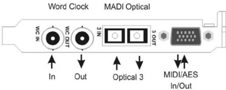
The included breakout cable is connected to the 15-pin D-sub connector and provides one MIDI input and output via 2 5-pin DIN connectors, and one AES input and output with XLR connectors.
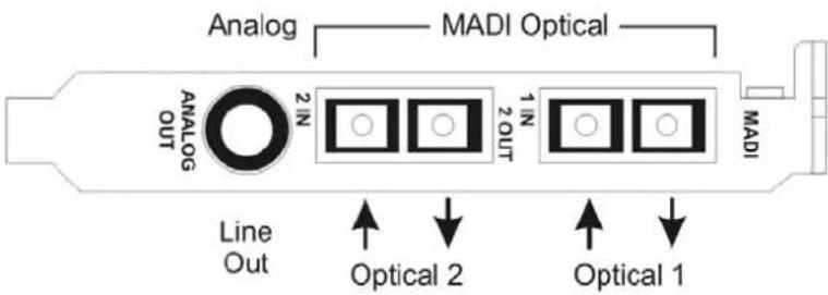
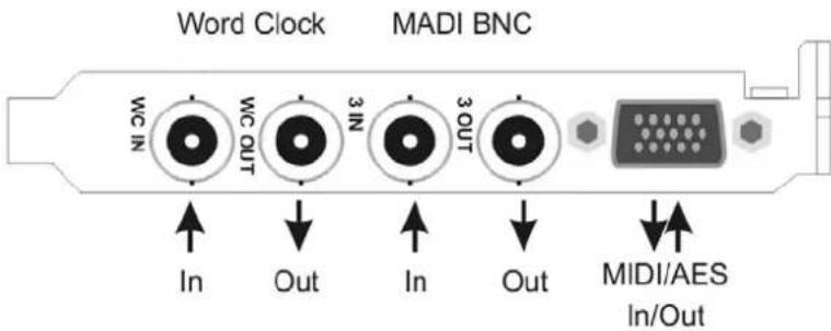
Note: If none of the connections of the expansion board are used or required, it is not necessary to install the board.
An expansion board with optical MADI I/O instead of coaxial is available separately (Opto-X). Connections and functions are all identical to the standard expansion board (BNC-X).
6.2 Internal Connectors
X1100 Sync In
Internal word clock input for synchronization of multiple cards via SYNC OUT.
X1101 Sync Out
This 3-pin connector carries an internal word clock signal. It can be used to synchronize multiple cards with sample accuracy, and without the need for an external connection. The card where SYNC OUT is used is master, the one with SYNC IN is slave. In the Settings dialog the slave has to be set to Sync In under Clock Mode – Clock Source.
X1102 – Expansion Board
20-pin connector for the included HDSPe MADI FX expansion board.
X200
No function. Used to program the card in the factory.
X606
2-pin connector fitted with a blue jumper. Warning: without this jumper the card will not work!
7. Accessories
RME offers several optional components. Additionally parts of the HDSPe MADI FX, like the special breakout cable, are available separately.
Part Number Description
BOAESMIDI AES/MIDI breakout cable
VKMADIFX 20-conductor flat ribbon cable
MADI0.5S MADI Optical Cable, Simplex, 0.5 m (1.6 ft)
MADI1S MADI Optical Cable, Simplex, 1 m (3.3 ft)
MADI3D MADI Optical Cable, Duplex, 3 m (9.9 ft)
MADI6D MADI Optical Cable, Duplex, 6 m (20 ft)
MADI10D MADI Optical Cable, Duplex, 10 m (33 ft)
MADI20D MADI Optical Cable, Duplex, 20 m (66 ft)
MADI50D MADI Optical Cable, Duplex, 50 m (165 ft)
MCD100 MADI Optical multicore on drum, 100 m
MCD150 MADI Optical multicore on drum, 150 m
MCD300 MADI Optical multicore on drum, 300 m
8. Warranty
Each individual HDSPe MADI FX undergoes comprehensive quality control and a complete test at IMM before shipping. The usage of high grade components should guarantee a long and trouble-free operation of the unit.
If you suspect that your product is faulty, please contact your local retailer.
Audio AG grants a limited manufacturer warranty of 6 months from the day of invoice showing the date of sale. The length of the warranty period is different per country. Please contact your local distributor for extended warranty information and service. Note that each country may have regional specific warranty implications.
In any case warranty does not cover damage caused by improper installation or maltreatment - replacement or repair in such cases can only be carried out at the owner's expense.
No warranty service is provided when the product is not returned to the local distributor in the region where the product had been originally shipped.
Audio AG does not accept claims for damages of any kind, especially consequential damage. Liability is limited to the value of the Hammerfall DSP. The general terms of business drawn up by Audio AG apply at all times.
9. Appendix
RME news, driver updates and further product information are available on our website:
http://www.rme-audio.com
Distributor:
Audio AG, Am Pfanderling 60, D-85778 Haimhausen, Tel.: (49) 08133 / 918170
Manufacturer:
IMM Elektronik GmbH, Leipziger Strasse 32, D-09648 Mittweida
Trademarks
All trademarks, registered or otherwise, are the property of their respective owners. RME, DIGICheck and Hammerfall are registered trademarks of RME Intelligent Audio Solutions. HDSPe MADI FX, HDSPe MADI, HDSP AES-32, OctaMic XTC, TMS, DIGI96, SyncAlign, ZLM, SyncCheck and TotalMix are trademarks of RME Intelligent Audio Solutions. Alesis and ADAT are registered trademarks of Alesis Corp. ADAT optical is a trademark of Alesis Corp. Microsoft, Windows 2000, Windows XP, Windows Vista and Windows 7/8 are registered trademarks or trademarks of Microsoft Corp. Steinberg, Cubase and VST are registered trademarks of Steinberg Media Technologies GmbH. ASIO is a trademark of Steinberg Media Technologies GmbH.
Copyright © Matthias Carstens, 07/2014. Version 1.4
Current driver version: Windows: 2.0, Mac OS X Intel: 1.14. Firmware: 89, DSP 21
TotalMix FX: 1.02
Although the contents of this User's Guide have been thoroughly checked for errors, RME can not guarantee that it is correct throughout. RME does not accept responsibility for any misleading or incorrect information within this guide. Lending or copying any part of the guide or the RME Driver CD, or any commercial exploitation of these media without express written permission from RME Intelligent Audio Solutions is prohibited. RME reserves the right to change specifications at any time without notice.
CE / FCC Compliance
CE
This device has been tested and found to comply with the limits of the European Council Directive on the approximation of the laws of the member states relating to electromagnetic compatibility according to RL2004/108/EG.
FCC
This equipment has been tested and found to comply with the limits for a Class B digital device, pursuant to Part 15 of the FCC Rules. These limits are designed to provide reasonable protection against harmful interference in a residential installation. This equipment generates, uses, and can radiate radio frequency energy and, if not installed and used in accordance with the instructions, may cause harmful interference to radio communications. However, there is no guarantee that interference will not occur in a particular installation. If this equipment does cause harmful interference to radio or television reception, which can be determined by turning the equipment off and on, the user is encouraged to try to correct the interference by one or more of the following measures:
- Reorient or relocate the receiving antenna.
- Increase the separation between the equipment and receiver.
- Connect the equipment into an outlet on a circuit different from that to which the receiver is connected.
- Consult the dealer or an experienced radio/TV technician for help.
RoHS
This product has been soldered lead-free and fulfils the requirements of the RoHS directive.
ISO 9001
This product has been manufactured under ISO 9001 quality management. The manufacturer, IMM Elektronik GmbH, is also certified for ISO 14001 (Environment) and ISO 13485 (medical devices).
Note on Disposal
According to the guide line RL2002/96/EG (WEEE – Directive on Waste Electrical and Electronic Equipment), valid for all european countries, this product has to be recycled at the end of its lifetime.
In case a disposal of electronic waste is not possible, the recycling can also be done by IMM Elektronik GmbH, the manufacturer of the HDSPe MADI FX.
For this the device has to be sent free to the door to:

natural_image
Symbol of a trash bin crossed with a diagonal line, representing waste sorting or disposal (no text or labels)
IMM Elektronik GmbH
Leipziger Straße 32
D-09648
Mittweida
Germany
Shipments not prepaid will be rejected and returned on the original sender's costs.
User's Guide

INTELLIGENT AUDIO SOLUTIONS
HDSPe MADI FX
Driver Installation and Operation - Windows
10. Driver and Firmware
10.1 Driver Installation
To simplify installation it is recommended to first install the drivers before the card is built into the computer. But it will also work the other way round.
Insert the RME Driver CD into your CD-ROM drive. The driver installer is located in the directory \HDSPe FX. Start rmeinstaller.exe and follow the instructions of the installer. After the HDSPe MADI FX has been installed correctly (see 5. Hardware Installation), and the computer has been switched on, Windows will detect the new hardware as HDSPe MADIface FX and install the drivers automatically.
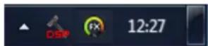
After a reboot, the icons of TotalMix FX and Settings dialog appear in the notification area.
Driver Updates do not require to remove the existing drivers. Simply install the new driver over the existing one.
10.2 De-Installing the Drivers
A de-installation of the HDSPe driver files is not necessary – and not supported by Windows anyway. Thanks to full Plug & Play support, the driver files will not be loaded after the hardware has been removed. If desired these files can then be deleted manually.
Unfortunately Windows Plug & Play methods do not cover the additional autorun entries of TotalMix, the Settings dialog, and the registration of the ASIO driver. Those entries can be removed from the registry through a software de-installation request. This request can be found (like all de-installation entries) in Control Panel, Software. Click on the entry 'RME HDSPe FX (WDM)'.
10.3 Firmware Update
The Flash Update Tool updates the HDSPe MADI FX to the latest firmware version. It requires an already installed driver.
Start the program hdspe_fx_fut.exe. The Flash Update Tool displays the current revision of the HDSPe MADI FX, and whether it needs an update or not. If so, then please press the 'Update' button. A progress bar will indicate when the flash process is finished. The bar moves slowly first (program), then faster (verify).
If more than one interface card is installed, all cards can be flashed by changing to the next tab and repeating the process.
After the update the PCI Express card needs to be reset. This is done by powering down and shutting off the PC. A warm boot is not enough!
To reduce the time needed for the flash process the tool updates only the parts of the firmware that are present in a newer version. The option Flash All forces the tool to update all parts.
When the update fails (status: failure), the card's second BIOS will be used from the next cold boot on (Secure BIOS Technology). Therefore the card stays fully functional. The flash process should then be tried again on a different computer.
11. Configuring the HDSPe MADI FX
11.1 Settings Dialog – Main Tab
Configuration of the HDSPe MADI FX is done via its own settings dialog. The panel 'Settings' can be opened:
- by clicking on the hammer symbol in the Task Bar's notification area
The mixer of the interface, TotalMix FX, can be opened:
- by clicking on the DSP-symbol in the Task Bar's notification area
The HDSPe hardware offers a number of helpful, well thought-of practical functions and options which affect how the card operates - it can be configured to suit many different requirements. The following is available in the 'Settings' dialog:
- Latency
• WDM Device Configuration - Current sample rate
• Synchronization behaviour - Configuration of digital I/Os
- Input selection
• State of input and output
Any changes made in the Settings dialog are applied immediately - confirmation (e.g. by clicking on OK or exiting the dialog) is not required.
However, settings should not be changed during playback or record if it can be avoided, as this can cause unwanted noises.
Also, please note that even in 'Stop' mode, several programs keep the recording and playback devices open, which means that any new settings might not be applied immediately.
The status displays at the bottom of the dialog box give the user precise information about the current status of the system, and the status of all digital signals.
The tab About provides information about the current driver version of the HDSPe MADI FX.
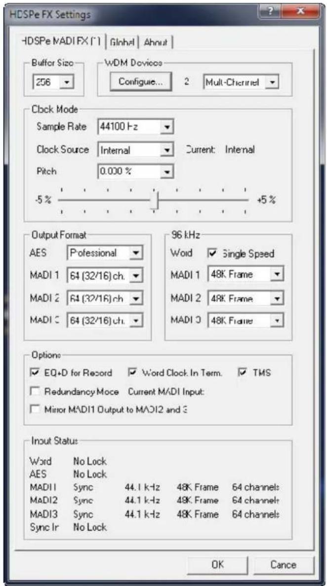
Buffer Size
The setting Buffer Size determines the latency between incoming and outgoing ASIO and WDM data, as well as affecting system stability (see chapter 13.1). While ASIO can use any offered buffer size, WDM is limited to 256 (XP) or 512 samples (Win 7/8). The driver handles this automatically, higher settings are only applied to ASIO while WDM will stay at 256/512 internally.
WDM Devices
Allows to freely set which I/Os are available as WDM devices, if these are stereo or multi-channel devices (up to 8 channels), and if one or multiple of the currently active WDM devices should have the Speaker property. More details are found in chapter 11.2.
Clock Mode
Sample Rate
Sets the currently used sample rate. Offers a central and comfortable way of configuring the sample rate of all WDM devices to the same value, as since Vista the audio software is no longer allowed to set the sample rate. However, an ASIO program can still set the sample rate by itself.
During record/playback the selection is greyed out, so no change is possible.
Clock Source
The unit can be configured to use its own clock (Internal = Master), or one of the input signals (Word, MADI, AES, Sync In). If the selected source isn't available (No Lock), the unit will change to the next available one (this behaviour is called AutoSync). If none is available then the internal clock is used. The current clock source is displayed as Current.
Pitch
More information on Pitch is available in chapter 11.4.
Output Format
AES
The channel status of the AES output signal can be set to Consumer or Professional. For further details please refer to chapter 23.2.
MADI 1/2/3
Defines the format of the MADI output signal. MADI can be a 56 or 64 channel signal.
96 kHz
Word
The word clock output signal usually equals the current sample rate. Selecting Single Speed causes the output signal to always stay within the range of 32 kHz to 48 kHz. So at 96 kHz and 192 kHz sample rate, the output word clock is 48 kHz.
MADI 1/2/3
Sample rates higher than 48 kHz can be transmitted using the normal 48K Frame, or using a native 96K Frame at the card's output.
Options
EQ+D for Record
Switches EQ and Dynamics of all input channels into the recording path. In case Loopback has been activated the EQ and Dynamics of the Output channel are within the recording path. See also chapter 27.5.
Word Clock In Term.
Checking this option terminates the word clock input internally with 75 Ohms.
TMS
TMS activates the transmission of Channel Status data and Track Marker information from the AES and MADI input signal.
Redundancy Mode
With redundancy mode active the number of input channels is reduced to 66 (AES plus 1x MADI). The two other MADI ports serve as fail safe inputs and are used as soon as the signal on the 'Current MADI Input' fails. This setting is also a perfect choice if the card is used as single MADI I/O, saving resources and providing simpler channel selection dialogs.
Mirror MADI1 Output to MADI2/3
This option provides a quick and simple solution to mirror the first MADI output to outputs 2 and 3. The outputs are reduced to 2+2+64 channels (AES, Phones and one MADI port). All the data routed and mixed to MADI port 1 is sent to MADI port 2/3 as well.
Input Status
Displays the state of the current input signal:
- Clock state (No Lock, Lock, Sync)
• Sample rate (coarse)
• MADI Frame format (48K or 96K)
• Channel format (64 or 56 channels)
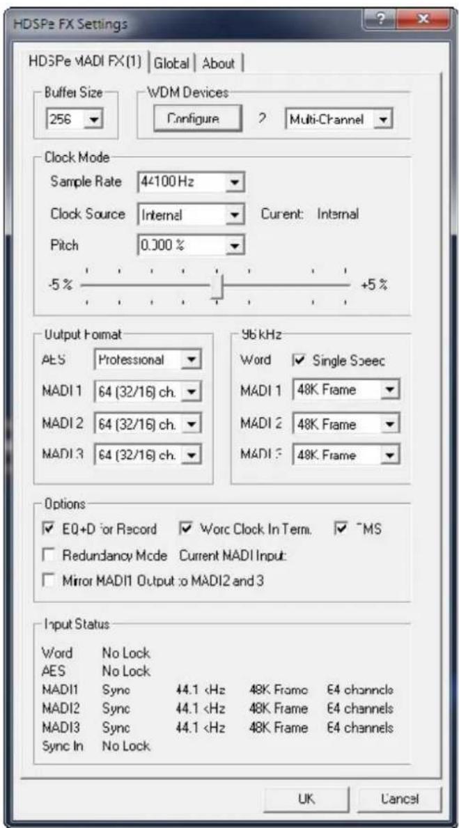
11.3 Tab Global
This tab includes several options that work on all currently installed cards.Lock Registry
Default: off. Checking this option brings up a dialog to enter a password. Changes in the Settings dialog are no longer written to the registry. As the settings are always loaded from the registry when starting the computer, this method provides an easy way to define an initial state of the HDSPe MADI FX.Optimize Multi-Client Mixing
Default: off. Checking this option removes short noise bursts when multi-client playback starts, but will also introduce some additional CPU load. Enable MMCSS for ASIO activates support with higher priority for the ASIO driver. Note: At this time, activating this option seems to be useful only with the latest Cubase/Nuendo at higher load. With other software this option can decrease performance. The change becomes active after an ASIO reset. Therefore it is easy to quickly check which setting works better.ASIO 32 Channel Limit
Default: off. Checking this option limits the number of ASIO I/Os to 32. Reducing the number of ASIO channels is required for older versions of ProTools to prevent them from crashing on start-up. Change Card Order
This dialog lists all cards currently installed in the system and controlled by the driver. Their order can then be changed by selecting a card and using the up/down arrows. Confirm the operation with the Apply button. This feature comes in handy if different cards are installed and a specific one of them should always be the first in the ASIO channel list. At the end of the card info line the current firmware version is shown (Revision).11.4 Settings Dialog - Pitch
Usually soundcards and audio interfaces generate their internal clock (master mode) by a quartz. Therefore the internal clock can be set to 44.1 kHz or 48 kHz, but not to a value in between. SteadyClock, RME's sensational Low Jitter Clock System, is based on a Direct Digital Synthesizer (DDS). This superior circuitry can generate nearly any frequency with highest precision. DDS has been implemented into the HDSPe MADI FX with regard to the needs of professional video applications, as well as to maximum flexibility. The section Pitch includes both a list of typical video frequencies (so called pull up/pull down at 0.1% and 4%) and a fader to freely change the basic sample rate in steps of 1 Hz (!) over a range of +/- 5%.  The Pitch function requires the HDSPe MADI FX to be in clock mode Master! The frequency setting will only be applied to this one specific card!  Changing the sample rate during record/playback often results in a loss of audio, or brings up warning messages of the audio software. Therefore the desired sample rate should be set at least coarsely before starting the software.Coarse
Coarse modification in steps of 50 Hz is done by clicking with the mouse to the left and right of the fader knob.Fine
Fine modification in steps of 1 Hz is done by using the left/right cursor keys.Reset
Ctrl key plus left mouse click. Application examples
Pitch allows for a simultaneous change of speed and tune during record and playback. From alignment to other sources up to creative effects – everything is possible. Pitch enables you to intentionally de-tune the complete DAW. This way, the DAW can match instruments which have a wrong or unchangeable tuning. Pitch allows for the change of the sample rate of all WDM devices at the same time. Since Vista this is no longer possible via the audio program, thus requires a manual reconfiguration of all WDM devices. Changing the sample rate from the Settings dialog solves this problem.11.5 Clock Modes - Synchronisation
In the digital world, all devices must be either Master (clock source) or Slave (clock receiver). Whenever several devices are linked within a system, there must always be a single master clock.  A digital system can only have one master! If the card's clock mode is set to 'Master', all other devices must be set to 'Slave'. The HDSPe MADI FX utilizes a very user-friendly, intelligent clock control, called AutoSync. In AutoSync mode, the system constantly scans the digital input for a valid signal. If any valid signal is found, the card switches from the internal quartz (Clock Mode – Current Internal) to a clock extracted from the input signal (Clock Mode – Current MADI, Word, AES or Sync In). The difference to a usual slave mode is that whenever the clock reference fails, the system will automatically use its internal clock and operate in clock mode Master. AutoSync guarantees that normal record and record-while-play will always work correctly. In certain cases however, AutoSync may cause feedback in the digital carrier, so synchronization breaks down. To remedy this, switch the HDSP clock mode to 'Internal'. RME's exclusive SyncCheck technology enables an easy to use check and display of the current clock status. Input Status indicates whether there is a valid signal (Lock, No Lock) for each input (Word, MADI, AES, Sync In), or if there is a valid and synchronous signal (Sync). See chapter 30.2. Via Clock Source a preferred input can be defined. As long as the card sees a valid signal there, this input will be designated as the sync source, otherwise the other inputs will be scanned in turn. If none of the inputs are receiving a valid signal, the card automatically switches clock mode to 'Master'. Under WDM the card will (has to) set the sample rate. Therefore the error shown to the right can occur. A stable signal with a sample rate of 32 kHz is detected at the Word Clock input (Sync), but Windows audio had been set to 44100 Hz before. The red colour of the text label signals the error condition, and prompts the user to set 32000 Hz manually as sample rate.  Under ASIO the audio software sets the sample rate, so that such an error will usually not happen – but it can too. In slave mode the external sample rate has priority. Feeding 44.1 kHz will prevent the ASIO software to set 48 kHz – obviously, as the only way to do so would be to enter a different clock mode (Master/Internal). In practice, SyncCheck provides the user with an easy way of checking whether all digital devices connected to the system are properly configured. With SyncCheck, finally anyone can master this common source of error, previously one of the most complex issues in the digital studio world.12. Operation and Usage
12.1 Playback
The HDSPe system can play back audio data in supported formats only (sample rate, bit resolution). Otherwise an error message appears (for example at 22 kHz and 8 bit). In the audio application being used, HDSPe must be selected as output device. This can often be found in the Options, Preferences or Settings menus under Playback Device, Audio Devices, Audio etc. We strongly recommend switching off all system sounds (via >Control Panel /Sounds<). Also HDSPe should not be the Preferred Device for playback, as this could cause loss of synchronization and unwanted noises. If you feel you cannot do without system sounds, you should use on-board sound or any cheap sound card and select this one as Preferred Device in >Control Panel /Multimedia /Audio< or >Control Panel /Sound /Playback<. The screenshot to the right shows a typical configuration dialog as displayed by a (stereo) wave editor. After selecting a playback device, audio data is sent to the according channels. Increasing the number and/or size of audio buffers may prevent the audio signal from breaking up, but also increases latency i.e. output is delayed. For synchronized playback of audio and MIDI (or similar), be sure to activate the checkbox 'Get position from audio driver'.  The HDSPe MADI FX allows sample rates of up to 192 kHz via MADI. In this mode, only 16 channels are functional per MADI port.Note on Windows Vista/7/8:
Since Vista the audio application can no longer control the sample rate under WDM. Therefore the driver of the HDSPe MADI FX includes a workaround: the sample rate can be set globally for all WDM devices within the Settings dialog, see chapter 11.1.12.2 DVD-Playback (AC-3/DTS)
AC-3 / DTS
When using popular DVD software players like WinDVD and PowerDVD, their audio data stream can be sent to any AC-3/DTS capable receiver via the HDSPe MADI FX. For this to work an output wave device has to be selected in >Control Panel/ Sounds and Multimedia/ Audio< or >Control Panel/ Sound/Playback<. Also check 'use preferred device only'. The DVD software's audio properties now show the options 'SPDIF Out' or similar. When selecting these, the software will transfer the non-decoded digital multichannel data stream to the HDSPe. Naturally a successful decoding also requires a MADI to AES converter like the RME ADI-642, converting the playback signals to stereo AES3 or SPDIF. Note: This 'SPDIF' signal sounds like chopped noise at highest level. The first 2 MADI channels (Loudspeaker) do not support digital AC-3/DTS playback.Multichannel
PowerDVD and WinDVD can also operate as software decoder, sending a DVD's multichannel data stream directly to the outputs of the HDSPe MADI FX. For this to work select the WDM playback device 'Loudspeaker' of the HDSPe MADI FX in XP: >Control Panel/ Sounds and Multimedia/ Audio<, and 'Use only default devices' has to be checked. Additionally the loudspeaker setup, found under >Volume/ Speaker Settings/ Advanced< has to be changed from Stereo to 5.1 Surround. Vista/7/8: >Control Panel/ Sound/ Playback < as 'Standard'. Additionally the loudspeaker setup, found under >Configuration<, might have to be changed from Stereo to 5.1 Surround. PowerDVD's and WinDVD's audio properties now list several multichannel modes. If one of these is selected, the software sends the decoded analog multichannel data to the HDSPe MADI FX. TotalMix can then be used to play back via any desired output channels. The typical channel assignment for surround playback is: 1 - Left 2 - Right 3 - Center 4 - LFE (Low Frequency Effects) 5 - SL (Surround Left) 6 - SR (Surround Right) Note 1: Setting the card to be used as system playback device is against common sense, as professional cards are not specialized to play back system sounds, and shouldn't be disturbed by system events. To prevent this be sure to re-assign this setting after usage or disable any system sounds (tab Sounds, scheme 'No audio'). Note 2: The DVD player will be synced backwards from the HDSPe card. So when using AutoSync and/or word clock, the playback speed and pitch follows the incoming clock signal.12.3 Multi-client Operation
RME audio interfaces support multi-client operation. Several programs can be used at the same time. The formats ASIO and WDM can even be used on the same playback channels simultaneously. As WDM uses a real-time sample rate conversion (ASIO does not), all active ASIO software has to use the same sample rate. However, a better overview is maintained by using the channels exclusively. This is no limitation at all, because TotalMix FX allows for any output routing, and therefore a playback of multiple software on the same hardware outputs. Inputs can be used from an unlimited number of WDM and ASIO software at the same time, as the driver simply sends the data to all applications simultaneously. RME's sophisticated tool DIGICheck is an exception to this rule. It operates like an ASIO host, using a special technique to access playback channels directly. Therefore DIGICheck is able to analyse and display playback data from any software, no matter which format it uses.12.4 Digital Recording
Unlike analog soundcards which produce empty wave files (or noise) when no input signal is present, digital interfaces always need a valid input signal to start recording. Taking this into account, RME added a comprehensive I/O signal status display to the HDSPe MADI FX, showing sample frequency, lock and sync status for every input. The sample frequency shown in the fields Clock Mode and Input Status is useful as a quick display of the current configuration of the unit and the connected external equipment. If no sample frequency is recognized, it will read 'No Lock'.| Input Status | ||||
| Word | No Lock | |||
| AES | No Lock | |||
| MADI1 | Sync | 44.1 kHz | 48K Frame | 64 channels |
| MADI2 | Sync | 44.1 kHz | 48K Frame | 64 channels |
| MADI3 | Sync | 44.1 kHz | 48K Frame | 64 channels |
| Sync In | No Lock | |||
13. Operation under ASIO
13.1 General
Start the ASIO software and select ASIO HDSPe FX as the audio I/O device. The HDSPe supports ASIO Direct Monitoring (ADM). The HDSPe MADI FX's MIDI I/O can be used with both MME MIDI and DirectMusic MIDI. At a sample rate of 88.2 or 96 kHz (Double Speed mode), the number of channels available at the MADI input and output is halved. At a sample rate of 176.4 or 192 kHz (Quad Speed mode), the number of channels is reduced to 16.  Note: When changing the sample rate range between Single, Double and Quad Speed the number of channels presented from the ASIO driver will change too. This may require a reset of the I/O list in the audio software.13.2 Known Problems
If a computer does not provide sufficient CPU-power and/or sufficient PCIe-bus transfer rates, then drop outs, crackling and noise will appear. Raising the buffer size in the Settings dialog of the HDSPe system helps in most cases. We recommend to deactivate all Plugins to verify that these are not the reason for such effects. Another common source of trouble is incorrect synchronization. ASIO does not support asynchronous operation, which means that the input and output signals not only have to use the same sample frequency, but also have to be in sync. Devices connected to the HDSPe MADI FX must be properly configured for Full Duplex operation. As long as SyncCheck (in the Settings dialog) only displays Lock instead of Sync, the devices have not been set up properly! The same applies when using more than one card - they all have to be in sync. Else a periodically repeated noise will be heard. RME supports ASIO Direct Monitoring (ADM). Please note that not all programs support ADM completely or error-free. The most often reported problem is the wrong behaviour of panorama in a stereo channel. In case of a drift between audio and MIDI, or in case of a fixed deviation (MIDI notes placed close before or behind the correct position), the settings in Cubase/Nuendo have to be changed. At the time of print the option 'Use System Timestamp' should be activated. The HDSPe system supports both MME MIDI and DirectMusic MIDI. It depends on the used application which one will work better.14. Using multiple HDSPe MADI FX
The current driver supports operation of up to three HDSPe MADI FX. All cards have to be in sync, i.e. have to receive valid sync information either via word clock or by using AutoSync and feeding synchronized signals. - If one of the HDSPe cards is set to clock mode Master, all others have to be set to clock mode Slave, and have to be synced from the master, for example by feeding word clock. The clock modes of all units have to be set up correctly in their Settings dialogs. - If all units are fed with a synchronous clock, i.e. all units show Sync in their Settings dialog, all channels can be used at once. This is especially easy to handle under ASIO, as the ASIO driver presents all cards as one. Note: TotalMix is part of the hardware of each HDSPe card. Up to three mixers are available, but these are separated and can't interchange data. Therefore a global mixer for all units is not possible.15. DIGICheck Windows
The DIGICheck software is a unique utility developed for testing, measuring and analysing digital audio streams. Although this software is fairly self-explanatory, it still includes a comprehensive online help. DIGICheck 5.71 operates as multi-client ASIO host, therefore can be used in parallel to any software with both inputs and outputs (!). The following is a short summary of the currently available functions: - Level Meter. High precision 24-bit resolution, 2/8/196 channels. Application examples: Peak level measurement, RMS level measurement, over-detection, phase correlation measurement, dynamic range and signal-to-noise ratios, RMS to peak difference (loudness), long term peak measurement, input check. Oversampling mode for levels higher than 0 dBFS. Vertical and horizontal mode. Slow RMS and RLB weighting filter. Supports visualization according to the K-system. - Hardware Level Meter for Input, Playback and Output. As above, receive pre-calculated directly from the HDSPe hardware with near zero CPU load. - Spectral Analyser. World wide unique 10-, 20- or 30-band display in analog bandpass-filter technology. 192 kHz-capable! - Vector Audio Scope. World wide unique Goniometer showing the typical afterglow of an oscilloscope-tube. Includes Correlation meter and level meter. - Totalyser. Spectral Analyser, Level Meter and Vector Audio Scope in a single window. - Surround Audio Scope. Professional Surround Level Meter with extended correlation analysis, ITU weighting and ITU summing meter. • ITU1770/EBU R128 Meter. For standardized loudness measurements. - Bit Statistics & Noise. Shows the true resolution of audio signals as well as errors and DC offset. Includes Signal to Noise measurement in dB and dBA, plus DC measurement. - Channel Status Display. Detailed analysis and display of SPDIF and AES/EBU Channel Status data. - Global Record. Long-term recording of all channels at lowest system load. - Completely multi-client. Open as many measurement windows as you like, on any channels and inputs or outputs! To install DIGICheck, go to the \DIGICheck directory on the RME Driver CD and run setup.exe. Follow the instructions prompted on the screen. DIGICheck is constantly updated. The latest version is always found on our website www.rme-audio.com, section Downloads / DIGICheck.16. Hotline – Troubleshooting
The newest information can always be found on our website www.rme-audio.com, section FAQ, Latest Additions. The dialog 'New hardware component found' does not appear: \- Check whether the PCI Express interface is correctly inserted in the PCI Express slot. The card and drivers have been installed correctly, but playback does not work: \- Check whether the HDSPe MADI FX appears in the Device Manager. When the device has a yellow exclamation mark, then there is a conflict. The input signal cannot be monitored in real-time \- ASIO Direct Monitoring has not been enabled, and/or monitoring has been disabled globally (wrong mix setup in TotalMix) Playback works, but record doesn't - Check that there is a valid signal at the input. If so, the current sample frequency is displayed in the Settings dialog. - Check whether the HDSPe system has been selected as recording device in the audio application. - Check whether the sample frequency set in the audio application ('Recording properties' or similar) matches the input signal. Crackle during record or playback - Increase the number and size of buffers in the 'Settings' dialog or in the application. - Try different cables (coaxial or optical) to rule out any defects here. - Check that cables/devices have not been connected in a closed loop. If so, set the system's clock mode to 'Internal'. Windows boot time became much worse since the FX card has been added \- Deactivate all WDM devices that are unused in the card's settings dialog. If only ASIO is used disable all. User's Guide  INTELLIGENT AUDIO SOLUTIONSHDSPe MADI FX
Driver Installation and Operation – Mac OS X17. Driver and Flash Update
17.1 Driver Installation
First fit the card (see 5. Hardware Installation), then switch on the computer and install the drivers from the RME Driver CD. The driver file is located in the folder HDSPe FX. Installation works automatically by a double-click on the file hdspe\_fx.pkg. RME recommends to download the latest driver version from the RME website. If done, the procedure is as follows: Double-click onto hdspe\_fx\_mac\_xxx.zip to expand the archive file to the folder hdspe\_xxx\_mac which includes the driver file hdspe\_fx.pkg. Installation works automatically by a double-click on this file. Reboot the computer when installation is done. During driver installation the programs HDSPe FX Settings and Totalmix (TotalMix FX) are copied to the Applications folder. They will automatically start into the dock. Driver Updates do not require to remove the existing drivers. Simply install the new driver over the existing one.17.2 De-installing the Drivers
In case of problems the driver files can be deleted manually by dragging them to the trash bin: /Applications/Totalmix /Applications/HDSPe FX Settings /Library/Audio/MIDI Drivers/HDSPe FX MIDI.plugin /System/Library/Extensions/HDSPe\_FX.kext /Users/username/Library/Preferences/RME TotalMix FX folder /Users/username/Library/Preferences/de.rme-audio.TotalmixFX.plist /Users/username/Library/Preferences/com.rme.HDSPe FX Settings.plist /Library/LaunchAgents/de.rme-audio.hdspe\_FX\_Launcher.plist Under the latest Mac OS the User/Library folder is not visible in the Finder. To unhide it start Finder, click on the menu item Go. Hold down the option (alt) key, then click on Library.17.3 Firmware Update
The Flash Update Tool updates the HDSPe MADI FX card to the latest firmware version. It requires an already installed driver. Start the program HDSPe FX Flash Update. The Flash Update Tool displays the current revision of the HDSPe card, and whether it needs an update or not. If so, then simply press the 'Update' button. A progress bar will indicate when the flash process is finished. The bar moves slowly first (program), then faster (verify). If more than one card is installed, all cards can be flashed by changing to the next tab and repeating the process. After the update the PCI Express card needs to be reset. This is done by powering down and shutting off the computer. A warm boot is not enough! To reduce the time needed for the flash process the tool updates only the parts of the firmware that are present in a newer version. The option Flash All forces the tool to update all parts. When the update fails (status: failure), the card's second BIOS will be used from the next cold boot on (Secure BIOS Technology). Therefore the card stays fully functional. The flash process should then be tried again on a different computer.18. Configuring the HDSPe MADI FX
18.1 Settings Dialog
Configuring the HDSPe MADI FX is done via its own settings dialog. The panel 'Settings' can be opened by clicking on the hammer icon in the dock. The mixer of the HDSPe MADI FX, TotalMix FX, can be opened by clicking on the DSP FX icon in the dock. The HDSPe hardware offers a number of helpful, well thought-of practical functions and options which affect how the card operates - it can be configured to suit many different requirements. The following is available in the 'Settings' dialog: - Configuration of digital I/Os - Hardware Options • Synchronization behaviour - Current sample rate • State of inputs and outputs Any changes performed in the Settings dialog are applied immediately - confirmation (e.g. by exiting the dialog) is not required. However, settings should not be changed during playback or record if it can be avoided, as this can cause unwanted noises. The status display at the bottom of the dialog box gives the user precise information about the current status of the system, and the status of all digital signals. Use the drop down menu Properties For to select the card to be configured. To the right the current firmware and driver version is shown. Output Format
AES
The channel status of the AES output signal can be set to Consumer or Professional. For further details please refer to chapter 23.2.MADI 1/2/3
Defines the format of the MADI output signal. MADI can be a 56 or 64 channel signal.96 kHz
Word
The word clock output signal usually equals the current sample rate. Selecting Single Speed causes the output signal to always stay within the range of 32 kHz to 48 kHz. So at 96 kHz and 192 kHz sample rate, the output word clock is 48 kHz.MADI 1/2/3
Sample rates higher than 48 kHz can be transmitted using the normal 48K Frame, or using a native 96K Frame at the card's output.Options
EQ+D for Record
Switches EQ and Dynamics of all input channels into the recording path. In case Loopback has been activated the EQ and Dynamics of the Output channel are within the recording path. See also chapter 27.5.Word Clock In Term.
Checking this option terminates the word clock input internally with 75 Ohms.Mirror MADI1 Output to MADI2 and 3
This option provides a quick and simple solution to mirror the first MADI output to outputs 2 and 3. The outputs are reduced to 2+2+64 channels (one MADI port). All the data routed and mixed to MADI port 1 is sent to MADI port 2 and 3 as well.Redundancy Mode
With redundancy mode active the number of input channels is reduced to 66 (AES plus one MADI). The two other MADI ports are used as fail safe inputs and are used as soon as the signal on the 'Current MADI Input' fails. This setting is also a perfect choice if the card is used as single MADI I/O, saving resources and providing simpler channel selection dialogs. Clock Mode
Sample Rate
Used to set the current sample rate. This is the same setting as in the Audio MIDI Setup, just added here for your convenience.Clock Source
The unit can be configured to use its own clock (Internal = Master), or one of the input signals (Word, MADI, AES, Sync In). If the selected source isn't available (No Lock), the unit will change to the next available one (this behaviour is called AutoSync). If none is available then the internal clock is used. The current clock source is displayed as Current Clock.Input Status
Displays the state of the current input signal: - Clock state (No Lock, Lock, Sync) • Sample rate (coarse) • MADI Frame format (48K or 96K) • Channel format (64 or 56 channels)Sync Check
RME's exclusive SyncCheck technology provides an easy to use check and display of the current clock status. The clock state column indicates whether no signal (No Lock), a valid signal (Lock) or a valid and synchronous signal (Sync) is present at each of the digital clock source inputs.18.2 Clock Modes - Synchronisation
In the digital world, all devices must be either Master (clock source) or Slave (clock receiver). Whenever several devices are linked within a system, there must always be a single master clock.  A digital system can only have one master! If the card's clock mode is set to 'Master', all other devices must be set to 'Slave'. The HDSPe MADI FX utilizes a very user-friendly, intelligent clock control, called AutoSync. In AutoSync mode, the system constantly scans the digital input for a valid signal. If any valid signal is found, the card switches from the internal quartz (Clock Mode – Current Internal) to a clock extracted from the input signal (Clock Mode – Current MADI, Word, AES or Sync In). The difference to a usual slave mode is that whenever the clock reference fails, the system will automatically use its internal clock and operate in clock mode Master. AutoSync guarantees that normal record and record-while-play will always work correctly. In certain cases however, AutoSync may cause feedback in the digital carrier, so synchronization breaks down. To remedy this, switch the HDSPe clock mode to 'Internal'. RME's exclusive SyncCheck technology enables an easy to use check and display of the current clock status. Input Status indicates whether there is a valid signal (Lock, No Lock) for each input (Word, MADI, AES, Sync In), or if there is a valid and synchronous signal (Sync). See chapter 30.2. Via Clock Source a preferred input can be defined. As long as the card sees a valid signal there, this input will be designated as the sync source, otherwise the other inputs will be scanned in turn. If none of the inputs are receiving a valid signal, the card automatically switches clock mode to 'Master'. In practice, SyncCheck provides the user with an easy way of checking whether all digital devices connected to the system are properly configured. With SyncCheck, finally anyone can master this common source of error, previously one of the most complex issues in the digital studio world.19. Mac OS X FAQ
19.1 MIDI doesn't work
In some cases the applications do not show the MIDI port. The reason for this is usually visible within the Audio MIDI Setup – MIDI Window. It displays no RME MIDI device, or the device is greyed out and therefore inactive. Mostly, removing the greyed out device and searching for MIDI devices again will solve the problem. The HDSPe MIDI driver is a plugin. During installation it will be copied to >Library/Audio/MIDI Drivers<. Its name is HDSPe FX MIDI.plugin. The file can be displayed in the Finder and also be removed by simply dragging it to the trash bin.19.2 Repairing Disk Permissions
Repairing permission can solve problems with the installation process - plus many others. To do this, launch Disk Utility located in Utilities. Select your system drive in the drive/volume list to the left. The First Aid tab to the right now allows you to check and repair disk permissions.19.3 Supported Sample Rates
RME's Mac OS X driver supports all sampling frequencies provided by the hardware. This includes 32 kHz and 64 kHz, and even 128 kHz, 176.4 kHz and 192 kHz. But not any software will support all the hardware's sample rates. The hardware's capabilities can easily be verified in the Audio MIDI Setup – Audio Window. Select the HDSPe MADI FX. A click on Format will list the supported sample frequencies.19.4 Various Information
The driver of the HDSPe MADI FX requires 10.6 or higher. Programs that don't support card or channel selection will use the device chosen as Input and Output in the System Preferences – Sound panel. Via Launchpad – Other – Audio MIDI Setup the MADI FX can be configured for the system wide usage in more detail. Programs that don't support channel selection will always use channels 1/2, the first stereo pair. To access other inputs, use the following workaround with TotalMix: route the desired input signal to output channels 1/2. In the channel settings of outputs 1/2 activate Loopback. Result: the desired input signal is now available at input channel 1/2, without further delay/latency. Use Configure Speakers to freely configure the stereo or multichannel playback to any available channels.20. Using multiple HDSPe MADI FX
OS X supports the usage of more than one audio device by the same audio software. This is done via the Core Audio function Aggregate Devices, which allows to combine several devices into one. The current driver supports up to three HDSPe in any combination. All units have to be in sync, i.e. have to receive valid sync information either via word clock or by feeding synchronized signals. - If one of the units is set to clock mode Master, all others have to be set to clock mode Slave, and have to be synced from the master, for example by feeding word clock. The clock modes of all units have to be set up correctly in the Settings dialog. - If all units are fed with a synchronous clock, i.e. all units show Sync in their Settings dialog, all channels can be used at once. Note: TotalMix is part of the hardware of each HDSPe card. Up to three mixers are available, but these are separated and can't interchange data. Therefore a global mixer for all units is not possible.21. DIGICheck Mac
The DIGICheck software is a unique utility developed for testing, measuring and analysing digital audio streams. Although this Windows software is fairly self-explanatory, it still includes a comprehensive online help. DIGICheck 0.683 operates in parallel to any software, showing all input data. The following is a short summary of the currently available functions: - Level Meter. High precision 24-bit resolution, 2/8/196 channels. Application examples: Peak level measurement, RMS level measurement, over-detection, phase correlation measurement, dynamic range and signal-to-noise ratios, RMS to peak difference (loudness), long term peak measurement, input check. Oversampling mode for levels higher than 0 dBFS. Vertical and horizontal mode. Slow RMS and RLB weighting filter. Supports visualization according to the K-System. - Hardware Level Meter for Input, Playback and Output. As above, receive pre-calculated directly from the HDSPe hardware with near zero CPU load. - Spectral Analyser. World wide unique 10-, 20- or 30-band display in analog bandpass filter technology. 192 kHz-capable! - Vector Audio Scope. World wide unique Goniometer showing the typical afterglow of a oscilloscope-tube. Includes Correlation meter and level meter. - Totalyser. Spectral Analyser, Level Meter and Vector Audio Scope in a single window. - Surround Audio Scope. Professional Surround Level Meter with extended correlation analysis, ITU weighting and ITU summing meter. - ITU1770/EBU R128 Meter. For standardized loudness measurements. - Bit Statistics & Noise. Shows the true resolution of audio signals as well as errors and DC offset. Includes Signal to Noise measurement in dB and dBA, plus DC measurement. - Completely multi-client. Open as many measurement windows as you like, on any channels and inputs or outputs! To install DIGICheck, go to the \DIGICheck directory on the RME Driver CD and run setup.exe. Follow the instructions prompted on the screen. DIGICheck is constantly updated. The latest version is always available on our website www.rme-audio.com, section Downloads / DIGICheck.22. Hotline – Troubleshooting
The newest information can always be found on our website www.rme-audio.com, section Support, Macintosh OS. Playback works, but record doesn't: - Check that there is a valid signal at the input. - Check whether the HDSPe MADI FX has been selected as recording device in the audio application. - Check whether the sample frequency set in the audio application ('Recording properties' or similar) matches the input signal. - Check that cables/devices have not been connected in a closed loop. If so, set the card's clock mode to Internal. Crackle during record or playback: - Increase the number and size of buffers in the application. - Try different cables to rule out any defects here. The card and drivers have been installed correctly, but playback does not work: - Is HDSPe MADI FX listed in the System Profiler/PCI? (Vendor 10EE, Device ID 3FC7). - Has HDSPe MADI FX been selected as current playback device in the audio application? User's Guide  INTELLIGENT AUDIO SOLUTIONSHDSPe MADI FX
▶ Inputs and Outputs23. Connections
23.1 MADI I/O
The BNC input is built according to AES10-1991. The input impedance is 75 Ohm. It will operate error-free from about 180 mVpp on. The optical input and output uses a FDDI (ISO/IEC 9413-3) compatible optical module, according to AES10-1991. More information can be found in chapter 30.1, MADI Basics. HDSPe MADI FX includes automatic input selection (Redundancy Mode). In case the current input signal fails, the unit switches to the other input immediately. This mode, called redundancy operation, offers improved safety against errors on the transmission line. Switching the inputs is done in less than a sample and - provided the input signal fails abruptly – click free. The BNC output is built according to AES10-1991. The output's impedance is 75 Ohm. The output voltage will be 600 mVpp when terminated with 75 Ohm. In MADI1 output mirror mode output 2 and 3 hold the same signal as MADI port 1. This mode allows for distributing a signal to three destinations, or redundant operation at the output of the card.23.2 AES/EBU
The XLR AES/EBU input and output are transformer-balanced and ground-free. The incoming channel status is ignored. Connection is accomplished using balanced cables with XLR plugs. AES/EBU (and SPDIF) can contain Emphasis information. Audio signals with Emphasis have a strong high frequency boost, requiring high frequency attenuation on playback.  An Emphasis indication gets lost as there exists no standardized interface on computers to handle this information!Input
Thanks to a highly sensitive input stage SPDIF coaxial can be fed too by using a simple cable adapter phono/XLR. To achieve this, pins 2 and 3 of a male XLR plug are connected individually to the two pins of a phono plug. The cable shielding is only connected to pin 1 of the XLR - not to the phono plug. Output
Using the cable adapter XLR/phono described above, devices with coaxial SPDIF interface can be connected to the AES output of the HDSPe MADI FX as well. Note that most consumer equipment with phono (SPDIF) inputs will only accept signals having a Channel Status 'Consumer' format. The Consumer status is activated in the Settings dialog. In Consumer mode the output voltage is reduced as well, as SPDIF calls for a lower voltage than AES/EBU. The output signal coding of the HDSPe MADI FX has been implemented according to AES3-1992 Amendment 4: • 32 / 44.1 / 48 kHz, 64 / 88.2 / 96 kHz, 176.4 / 192 kHz depending on the current sample rate - Audio use • No Copyright, Copy permitted - Format Professional or Consumer - Category General, Generation not indicated • 2-Channel, No Emphasis • Aux Bits Audio use, 24 Bit - Origin: MAFX23.3 Line - Headphones
HDSPe MADI FX offers a hi-quality analog monitor output. The short circuit protected stereo line output provides high output level, low impedance, and is available via a 6.3 mm (1/4") TRS jack. Therefore it is also suitable for a direct use with headphones. The analog output is directly driven from the channels 3/4. Its output volume is controlled by the hardware output faders of channel 3/4 in TotalMix. Additionally the analog output can play back any input or playback signal using TotalMix. The analog output does not include speaker protection. When switching the computer on and off, noise may occur at the analog outputs. In case the output should operate as line out, an adapter TRS plug to RCA phono plugs, or TRS plug to TS plugs is required. The pin assignment follows international standards. The left channel is connected to the tip, the right channel to the ring of the TRS jack/plug.  23.4 MIDI
The HDSPe MADI FX offers one MIDI I/O via 5-pin DIN connectors. The MIDI port is added to the system by the driver. Using MIDI capable software, the port can be accessed under the name MADI MIDI. Using more than one HDSPe MADI FX, a consecutive number is added to the port name, like MADI MIDI In 1 (2) etc. The three software-only MIDI ports receive and transmit MIDI data via MADI. This allows for a direct communication between systems with HDSPe MADI FX cards. Additionally MIDI data can be transmitted from/to other RME devices with MADI ports, without any additional line or cabling between computer (MADI card) and units. The MIDI ports support multi-client operation. A MIDI input signal can be received from several programs at the same time. Even the MIDI outputs can be used by multiple programs simultaneously. However, due to the limited bandwidth of MIDI, this kind of application will often show various problems.24. Word Clock
24.1 Word Clock Input and Output
SteadyClock guarantees an excellent performance in all clock modes. Based on the highly efficient jitter suppression, the HDSPe MADI FX refreshes and cleans up any clock signal, and provides it as reference clock at the BNC output (see chapter 30.6).Input
The HDSPe MADI FX word clock input is active when Clock Source in the Settings dialog has been switched to Word Clock, and a valid word clock signal is present. The signal at the BNC input can be Single, Double or Quad Speed, the HDSPe MADI FX automatically adapts to it. As soon as a valid signal is detected the Settings dialog shows either Lock or Sync (see chapter 30.2). Thanks to RME's Signal Adaptation Circuit, the word clock input still works correctly even with heavily mis-shaped, dc-prone, too small or overshoot-prone signals. Thanks to automatic signal centering, 300 mV (0.3V) input level is sufficient in principle. An additional hysteresis reduces sensitivity to 1.0 V, so that over- and undershoots and high frequency disturbances don't cause a wrong trigger. The word clock input is shipped as high impedance type (not terminated). The Settings dialog allows to activate internal termination (75 Ohms). Activate the option Word Clock Input Termination.Output
The word clock output of the HDSPe MADI FX is constantly active, providing the current sample frequency as word clock signal. As a result, in master mode the provided word clock is defined by the currently used software or the pitch setting. In slave mode the provided frequency is identical to the one present at the currently chosen clock input. When the current clock signal fails, the HDSPe MADI FX switches to master mode and adjusts itself to the next, best matching frequency (44.1 kHz, 48 kHz etc.). Selecting Single Speed in the Settings dialog causes the output signal to always stay within the range of 32 kHz to 48 kHz. So at 96 kHz sample rate, the output word clock is 48 kHz. The received word clock signal can be distributed to other devices by using the word clock output. With this the usual T-adapter can be avoided, and the HDSPe MADI FX operates as Signal Refresher. This kind of operation is highly recommended, because - input and output are phase-locked and in phase (0°) to each other - SteadyClock removes nearly all jitter from the input signal - the exceptional input (1 Vpp sensitivity instead of the usual 2.5 Vpp, dc cut, Signal Adaptation Circuit) plus SteadyClock guarantee a secure function even with highly critical word clock signals Thanks to a low impedance, but short circuit proof output, the HDSPe MADI FX delivers 4 Vpp to 75 Ohms. For wrong termination with 2 x 75 Ohms (37.5 Ohms), there are still 3.3 Vpp fed into the network – per output!24.2 Technical Description and Usage
In the analog domain one can connect any device to another device, a synchronisation is not necessary. Digital audio is different. It uses a clock, the sample frequency. The signal can only be processed and transmitted when all participating devices share the same clock. If not, the signal will suffer from wrong samples, distortion, crackle sounds and drop outs. AES/EBU, SPDIF, ADAT and MADI are self-clocking, an additional word clock connection in principle isn't necessary. But when using more than one device simultaneously problems are likely to happen. For example any self-clocking will not work in a loop cabling, when there is no 'master' (main clock) inside the loop. Additionally the clock of all participating devices has to be synchronous. This is often impossible with devices limited to playback, for example CD players, as these have no SPDIF input, thus can't use the self clocking technique as clock reference. In a digital studio synchronisation is maintained by connecting all devices to a central sync source. For example the mixing desk works as master and sends a reference signal, the word clock, to all other devices. Of course this will only work as long as all other devices are equipped with a word clock or sync input, thus being able to work as slave (some professional CD players indeed have a word clock input). Then all devices get the same clock and will work in every possible combination with each other.  Remember that a digital system can only have one master! But word clock is not only the 'great problem solver', it also has some disadvantages. The word clock is based on a fraction of the really needed clock. For example SPDIF: 44.1 kHz word clock (a simple square wave signal) has to be multiplied by 256 inside the device using a special PLL (to about 11.2 MHz). This signal then replaces the one from the quartz crystal. Big disadvantage: because of the high multiplication factor the reconstructed clock will have great deviations called jitter. The jitter of a word clock is multiple times higher than the one of a quartz based clock. The end of these problems should have been the so called Superclock, which uses 256 times the word clock frequency. This equals the internal quartz frequency, so no PLL for multiplying is needed and the clock can be used directly. But reality was different, the Superclock proved to be much more critical than word clock. A square wave signal of 11 MHz distributed to several devices - this simply means to fight with high frequency technology. Reflections, cable quality, capacitive loads - at 44.1 kHz these factors may be ignored, at 11 MHz they are the end of the clock network. Additionally it was found that a PLL not only generates jitter, but also rejects disturbances. The slow PLL works like a filter for induced and modulated frequencies above several kHz. As the Superclock is used without any filtering such a kind of jitter and noise suppression is missing. The actual end of these problems is offered by the SteadyClock technology of the HDSPe MADI FX. Combining the advantages of modern and fastest digital technology with analog filter techniques, re-gaining a low jitter clock signal of 22 MHz from a slow word clock of 44.1 kHz is no problem anymore. Additionally, jitter on the input signal is highly rejected, so that even in real world usage the re-gained clock signal is of highest quality. This is especially true when extracting the word clock out of a MADI signal. Caused by the MADI format itself, such a signal will have around 80 ns of jitter, which is reduced to about 1 ns by SteadyClock.24.3 Cabling and Termination
Word clock signals are usually distributed in the form of a network, split with BNC T-adapters and terminated with resistors. We recommend using off-the-shelf BNC cables to connect all devices, as this type of cable is used for most computer networks. You will find all the necessary components (T-adapters, terminators, cables) in most electronics and/or computer stores. The latter usually carries 50 Ohms components. The 75 Ohms components used for word clock are part of video technology (RG59). Ideally, the word clock signal is a 5 Volt square wave with the frequency of the sample rate, of which the harmonics go up to far above 500 kHz. To avoid voltage loss and reflections, both the cable itself and the terminating resistor at the end of the chain should have an impedance of 75 Ohm. If the voltage is too low, synchronization will fail. High frequency reflection effects can cause both jitter and sync failure. Unfortunately there are still many devices on the market, even newer digital mixing consoles, which are supplied with a word clock output that can only be called unsatisfactory. If the output breaks down to 3 Volts when terminating with 75 Ohms, you have to take into account that a device, of which the input only works from 2.8 Volts and above, does not function correctly already after 3 meter cable length. So it is not astonishing that because of the higher voltage, word clock networks are in some cases more stable and reliable if cables are not terminated at all. Ideally all outputs of word clock delivering devices are designed with very low impedance, but all word clock inputs as high impedance types, in order to not weaken the signal on the chain. But there are also negative examples, when the 75 Ohms are built into the device and cannot be switched off. In this case the network load is often 2 x 75 Ohms, and the user is forced to buy a special word clock distributor. Note that such a device is generally recommended for bigger studios. The HDSPe MADI FX word clock input can be high-impedance or terminated internally, ensuring maximum flexibility. If termination is necessary (e.g. because the card is the last device in the chain), activate the option Word Clock In Term. in the Settings dialog. In case the HDSPe MADI FX resides within a chain of devices receiving word clock, plug a T-adapter into its BNC input jack, and the cable supplying the word clock signal to one end of the adapter. Connect the free end to the next device in the chain via a further BNC cable. The last device in the chain should be terminated using another T-adapter and a 75 Ohm resistor (available as short BNC plug). Of course devices with internal termination do not need T-adaptor and terminator plug.  Due to the outstanding SteadyClock technology of the HDSPe MADI FX, we recommend not to pass the input signal via T-adapter, but to use the card's word clock output instead. Thanks to SteadyClock, the input signal will both be freed from jitter and - in case of loss or drop out – be reset to a valid frequency. User's Guide  INTELLIGENT AUDIO SOLUTIONSHDSPe MADI FX
TotalMix FX25. TotalMix: Routing and Monitoring
25.1 Overview
The HDSPe MADI FX includes a powerful digital real-time mixer, the Hammerfall DSP mixer, based on RME's unique, sample-rate independent TotalMix technology. It allows for practically unlimited mixing and routing operations, with all inputs and playback channels simultaneously, to any hardware outputs. Here are some typical applications for TotalMix: - Setting up delay-free submixes (headphone mixes). The HDSPe MADI FX allows for up to 98 (!) fully independent stereo submixes. On an analog mixing desk, this would equal 196 (!) Aux sends. - Unlimited routing of inputs and outputs (free utilisation, patchbay functionality). - Distributing signals to several outputs at a time. TotalMix offers state-of-the-art splitter and distributor functions. - Simultaneous playback of different programs using only one stereo output. The ASIO multi-client driver handles several programs at the same time, even identical playback channels. TotalMix provides the means to mix and monitor these on a single stereo output, even when originating on different playback channels. - Mixing of the input signal to the playback signal (complete ASIO Direct Monitoring). RME not only is the pioneer of ADM, but also offers the most complete implementation of the ADM functions. - Integration of external devices. Use TotalMix to insert external effects devices, be it in the playback or in the record path. Depending on the current application, the functionality equals insert or effects send and effects return, for example as used during real-time monitoring when adding some reverb to the vocals. Every single input channel, playback channel and hardware output features a Peak and RMS level meter, calculated in hardware (hardware output is Peak only). These level displays are very useful to determine the presence and routing destinations of the audio signals. For a better understanding of the TotalMix mixer you should know the following: - As shown in the block diagram (next page), the record signal usually stays un-altered. TotalMix does not reside within the record path, and does not change the record level or the audio data to be recorded (exception: loopback mode). - The hardware input signal can be passed on as often as desired, even with different levels. This is a big difference to conventional mixing desks, where the channel fader always controls the level for all routing destinations simultaneously. - The level meter of inputs and playback channels are connected pre-fader, to be able to visually monitor where a signal is currently present. The level meters of the hardware's outputs are connected post-fader, thus displaying the actual output level. flowchart
graph TD
    A["Hardware Input Channel 1 (1 of 194)"] --> B["Record Ch.1"]
    B --> C["Audio Software"]
    C --> D["Playback Ch.1 (1 of 196)"]
    D --> E["RMS Peak"]
    E --> F["Solo/ Mute"]
    F --> G["VOL"]
    G --> H["PAN"]
    H --> I["Mix"]
    I --> J["VOL Peak"]
    J --> K["Hardware Output Channel 1"]
    D --> L["Solo/ Mute"]
    L --> M["VOL"]
    M --> N["PAN"]
    N --> O["Mix"]
    O --> P["VOL Peak"]
    P --> Q["Hardware Output Channel 2"]
    D --> R["Solo/ Mute"]
    R --> S["VOL"]
    S --> T["PAN"]
    T --> U["Mix"]
    U --> V["VOL Peak"]
    V --> W["Hardware Output Channel 3 (etc)"]
    style A fill:#f9f,stroke:#333
    style B fill:#ccf,stroke:#333
    style C fill:#cfc,stroke:#333
    style D fill:#fcc,stroke:#333
    style E fill:#ffc,stroke:#333
    style F fill:#cfc,stroke:#333
    style G fill:#fcc,stroke:#333
    style H fill:#ffc,stroke:#333
    style I fill:#cfc,stroke:#333
    style J fill:#fcc,stroke:#333
    style K fill:#ffc,stroke:#333
    style L fill:#cfc,stroke:#333
    style M fill:#fcc,stroke:#333
    style N fill:#ffc,stroke:#333
    style O fill:#cfc,stroke:#333
    style P fill:#fcc,stroke:#333
    style Q fill:#ffc,stroke:#333
25.2 The User Interface
The visual design of the TotalMix mixer is a result of its capability to route hardware inputs and software playback channels to any hardware output. The HDSPe MADI FX provides 194 input channels, 196 software playback channels, and 196 hardware output channels: flowchart
graph TD
    A["HARDWARE INPUTS"] --> C["Hardware OUTPUTS"]
    B["SOFTWARE PLAYBACK"] --> C["Hardware OUTPUTS"]
flowchart
graph TD
    A["Hardware INPUTS"] --> B["SOFTWARE PLAYBACK"]
    B --> C["Hardware OUTPUTS"]
    C --> A
25.3 The Channels
A single channel can be switched between mono and stereo mode. The mode is set in the channel settings. Channel name. The name field is the preferred place to select a channel by a mouse click. A double click opens a dialog to assign a different name. The original name will be shown when activating the option Names in the View Options. Panorama. Routes the input signal freely to the left and right routing destination (lower label, see below). The level reduction in center position is -3 dB. Mute and Solo. Input channels and playback channels each have a mute and solo button. Numerical level display. Shows the current RMS or Peak level, updated twice per second. OVR means overload. The setting Peak/RMS is changed in the View Options. Level meter. The meter shows both peak values (zero attack, 1 sample is enough for a full scale display) by means of a yellow line, and mathematically correct RMS values by means of a green bar. The RMS display has a relatively slow time constant, so that it shows the average loudness quite well. Overs are shown in red at the top of the bar. In the Preferences dialog (F2) the Peak Hold time, the over detection and the RMS reference can be set.  Fader. Determines the gain/level of the signal routed to the current routing destination (lower label). Please note that this fader is not the fader of the channel, but only the fader of the current routing. Compared to a standard mixing desk TotalMix does not have a channel fader, but only Aux Sends, as many as there are hardware outputs. Therefore TotalMix can create as many different Submixes as there are hardware outputs. This concept is understood best in the Submix View, but more on that later. Below the fader the Gain is shown in a numerical display field, according to the current fader position. The fader can be: - dragged with the left mouse button pressed moved by the mouse wheel set to 0 dB and - by a double click. The same happens with a single click plus held down Ctrl key. adjusted in fine mode by mouse drag and mouse wheel when holding the Shift key down A Shift-click on a fader adds the fader to the temporary fader group. All faders now marked yellow are ganged, and move simultaneously in a relative way. The temporary fader group is deleted by a click on the F symbol in the upper right of the window.  The arrow symbol at the bottom minimizes the channel width to that of the level meters. Another click maximizes it again. A mouse click with held Ctrl key causes all channels to the right to enlarge and minimize at once. The lowest field shows the current routing target. A mouse click opens the routing window to select a routing target. The list shows all activated routings of the current channel by arrows in front of the listed entries. The current one is shown in bold letters. An arrow is only shown with an activated routing. A routing is seen as activated when audio data is sent. As long as the fader is set to - the current routing will be shown in bold letters, but not have an arrow in the front.  Trim Gain. After a click on the T-button one channel's faders are all synchronized. Instead of changing only a single routing the fader affects all the channel's active routings. For a better overview the faders currently not visible are indicated by orange triangles beside the fader path. When moving the fader the triangles also move to a new position, equalling the faders new settings. Note that the fader button is set to the highest routing gain of all routings so that best control is offered. The gain (fader knob position) of the currently active routing (the submix selected in the third row) is shown as white triangle. Background: TotalMix has no fixed channel fader. In case of the HDSPe MADI FX there are 98 stereo Aux sends, shown alternately as single fader within the channel strip. The high number of Aux sends enables multiple and fully independent routings. In some cases it is necessary to synchronize the gain changes of these routings. An example is the Post fader function, where a change of the singer's volume shall be performed identical to the volume change of the signal sent to the reverb device, so that the reverb level keeps its relation to the original signal. Another example is the signal of a guitar that is routed to different submixes, means hardware outputs, which gets much too loud during the solo part, and therefore needs to be reduced in volume on all outputs simultaneously. After a click on the Trim button this can be done easily and with a perfect overview. As all channel's routings change simultaneously when Trim is active, this mode basically causes the same behaviour as a trim pot within the input channel, affecting the signal already before the mixer. That's how this function got its name.  In the View Options - Show the function Trim Gains can be globally switched on and off for all channels. The global Trim mode is recommended when using TotalMix FX as live mixing desk.25.3.1 Settings
A click on the tool symbol opens the channel's Settings panel. It includes these elements: Stereo. Switches the channel to mono or stereo mode. Width. Defines the stereo width. 1.00 equals full stereo, 0.00 mono, -1.00 swapped channels. FX Send. Setting the level of the signal sent to the FX bus which feeds Echo and Reverb. The current setting is also visible with closed channel settings, because knob and small fader are always synchronized. To make this function as useful as possible FX Send is locked to the highest submix, thus imitating the Aux Post Fader function of a standard mixing desk. When moving the big fader both knob and small fader will also move. This way the reverb signal will always have the same relation to the dry signal. The level of the signal sent to the effects can be controlled by the FX In level meters of the FX window. It becomes visible after a click on FX in the View Options. MS Proc. Activates M/S processing within the stereo channel. Monaural information is sent to the left channel, stereo information to the right.  Phase L. Inverts the phase of the left channel by 180°. Phase R. Inverts the phase of the right channel by 180°. Note: the functions Width, MS Proc, Phase L and Phase R affect all routings of the respective channel. The Hardware Outputs have no width option, but two other options: FX Return. The effect signal (Echo and Reverb) is mixed to the respective hardware output by the duo knob/small fader. Talkback. Activates this channel as receiver and output of the Talkback signal. This way Talkback can be sent to any outputs, not only the Phones in the Control Room section. Another application could be to send a certain signal to specific outputs by the push of a button. No Trim. Sometimes channels need to have a fixed routing and level, which should not be changed in any case. An example is the stereo mixdown for recording of a live show. With No Trim active, the routing to this output channel is excluded from the Trim Gains function, therefore is not changed unintentionally. Loopback. Sends the output data to the driver as record data. The corresponding submix can be recorded then. This channel's hardware input sends its data only to TotalMix, no longer to the recording software.  Another difference to the input and playback channels is the Cue button instead of Solo. A click on Cue sends the respective Hardware Output's audio to the Main Out, or any of the Phones outputs (option Assign / Cue to in the Control Room section). With this any hardware output can be controlled and listened to through the monitoring output very conveniently.25.3.2 Equalizer
A click on EQ opens the Equalizer panel. It is available in all input and output channels, and affects all routings of the respective channel (pre fader). The panel includes a low cut and a 3-band parametric equalizer which can be activated separately. EQ. Activated by the EQ button. Type. Band 1 and 3 can operate in peak (bell) or shelf (shelving) mode. The middle band is fixed to peak mode. Band 3 can also operate as Hi Cut (low pass filter), especially useful for LFE and subwoofer purposes. Gain. All three bands can change their amplification between +20 dB to -20 dB. Freq. The center frequency of the filters is adjustable between 20 Hz and 20 kHz. While in peak mode the center frequency is adjusted, in shelf mode the cut-off point (-3 dB) will be changed. Q. The Quality factor of the filter is adjustable from 0.7 (wide) to 5.0 (narrow).  Lo Cut. Activated by the button Lo Cut. The slope of the high-pass filter is adjustable between 6, 12, 18 and 24 dB per octave. The cut-off point (-3 dB) is adjustable between 20 Hz and 500 Hz. The frequency graphics give a precise overview of the filter results. Overlapping filters influence each other. This can be used to achieve more than 20 dB amplitude, or to generate difficult frequency response optimizations. Note: TotalMix has internal headroom of 24 dB. Extreme boosts with overlapping filters can therefore cause an internal overload. In any case such an overload is displayed by the Over LED of the channel's level meter. Preset. Settings of the EQ and the Low Cut can be stored, loaded, and copied between channels at any time. A click on Preset opens a menu with several entries: ➢ Recall: Presets stored before by the user can be selected and loaded Save to: There are 16 storage places available (EQ Preset 1 to 16) Import: Loads a previously stored TM EQ file (.tmeq) ➢ Export: Stores the current state as TM EQ file (.tmeq) ➢ Factory: Includes 14 examples for the creative use of Low Cut and Equalizer Reset: Resets the Low Cut and EQ to have zero influence (Gain 0 dB) Rename: The EQ Presets 1 to 16 can be renamed. The changes will be shown in both lists Recall and Save to. Notes on the EQ Presets
Copy between channels: The EQ Preset menu of all channels is identical. If an EQ setup is stored via Save to on one of the 16 storage places, it is then also available in any other channel via Recall. Copy between Snapshots: The Presets are not saved in Snapshots, therefore do not change when a different Snapshot is loaded. Presets are saved in Workspaces and also loaded with these. Copy between Workspaces: is done by the export and import function of the Preset menu. Important and useful Presets should always be saved as TM EQ file, so that they can not get lost even on accidental overwrite. Factory Presets: loaded like all Presets the settings of both Low Cut and EQ simultaneously. The current state, On or Off, is neither saved nor activated on load. With this a preset can be loaded anytime, but will not become active before the user decides to switch the EQ and/or LC on – except they had been active already before the load process. For this reason some Factory Presets have special names. For example Telephone (LC+EQ) will sound much better when the LC has been activated additionally to the EQ, as the LC is set to an unusual high frequency of 500 Hz here.25.3.3 Dynamics
A click on D opens the Dynamics panel with Compressor, Expander and Auto Level. They are available in all input and output channels, and affects all routings of the respective channel. Dynamics. Activated by this button. Thresh. Threshold where Compressor or Expander start to work. The Compressor is adjustable from -60 dB to 0 dB, the Expander is adjustable from -99 dB to -30 dB. Ratio. Ratio of input to output signal. Defines the intensity of the signal processing. Adjustable from 1 to 10. Gain. Gain stage to compensate a loss in level caused by the Compressor. Adjustable from -30 to +30 dB. With inactive Compressor (Threshold 0 dB, Gain 1:1) this function can also be used as universal digital gain stage. Attack. Defines the rise time for the control voltage of Compressor/Expander. Adjustable from 0 ms to 200 ms.  Release. Defines the release time for the control voltage of Compressor and Expander. Adjustable from 100 ms to 999 ms. The amplitude graphics gives a precise overview of the level changes caused by the current settings of Compressor and Expander. The white dot shows the level of the input signal and with this whether the signal is within the processing range or not. The small light blue lines in the level meter show the currently active gain reduction. Settings for these Dynamic Meters are found in the Preferences dialog (F2). Auto Level. Activated by this button. Max. Gain. Defines the maximum amplification of the input signal. Adjustable from 0 dB to 18 dB. Headroom. To minimize short-time overloads and clipping of the signal peaks Auto Level can be set to operate at a fixed offset to 0 dBFS. Adjustable from 3 dB to 12 dB. Rise Time. Defines the speed of a level increase after a level reduction. Adjustable from 0.1 s to 9.9 s. Preset. Includes the same functions as described on the previous page for the Equalizer. The names of the Factory Presets make clear whether Compressor, Auto Level or both (C+A) have to be switched on. 25.4 Section Control Room
In the section Control Room the menu Assign is used to define the Main Out which is used for listening in the studio. For this output the functions Dim, Recall, Mono, Talkback, External In and Mute FX are automatically applied. Additionally the channel will be shifted from the Hardware Outputs into the Control Room section, and renamed Main. The same happens when assigning Main Out B or the Phones. The original name can be displayed by the function Names in the View Options - Show at any time. Phones 1 to 4 will have Dim (set in Settings) and a special routing applied when Talkback is activated. Also putting them beside the Main Out increases the overview within the output section greatly. Dim. The volume will be reduced by the amount set in the Settings dialog (F3). Recall. Sets the gain value defined in the Settings dialog. Speaker B. Switches playback from Main Out to Main Out B. The faders of the channels Main and Speaker B can be ganged via Link.  Mono. Mixes left and right channel. Useful to check for mono compatibility and phase problems. Talkback. A click on this button will dim all signals on the Phones outputs by an amount set up in the Preferences dialog. At the same time the control room's microphone signal (source defined in Preferences) is sent to the Phones. The microphone level is adjusted with the channel's input fader. External Input. Switches Main monitoring from the mix bus to the stereo input defined in the Settings dialog (F3). The relative volume of the stereo signal is adjusted there as well. Mute FX. Mutes Reverb and Echo on the Main Out, to hear the mix without those effects. Assign. Allows to define the Main Out, Main Out B (Speaker B), and up to four Phones outs. The choice is limited to AES, Phones and MADI 1 to 16, as the higher channels are not available at 192 kHz. The output for the Cue signal, which is usually Main, can also be set to one of the four Phones outputs. This setting also controls the PFL monitoring. 25.5 The Control Strip
The Control Strip on the right side is a fixed element. It combines different functions that are either required globally, or constantly used, and therefore should not be hidden in a menu. Device selection. Select the unit to be controlled in case more than one is installed on the computer. FX - DSP Meter. Shows the DSP load caused by activated EQ, Low Cut, Compressor, Auto Level, Echo and Reverb. The DSP of the HDSPe MADI FX has an automatic load limiter. If no DSP resources are left further effects can not be activated. When switching to DS and QS modes effects will be deactivated automatically until the DSP is not overloaded anymore. Undo / Redo. With the unlimited Undo and Redo changes of the mix can be undone and redone, at any time. Undo/Redo does not cover graphical changes (window size, position, channels wide/narrow etc.), and also no changes to the Presets. The accidental overwrite of an EQ Preset can not be made undone. Undo/Redo also operates across Workspaces. Therefore a completely differently set up mixer view can be loaded via Workspace, and with a single click on Undo the previous internal mixer state is returned – but the new mixer view stays. Global Mute Solo Fader.
Mute. Global Mute operates in a pre fader style, muting all currently activated routings of the channel. As soon as any Mute button is pressed, the Mute Master button lights up in the Control Strip area. With this button all selected mutes can be switched off and on again. One can comfortably set up a mute group or activate and deactivate several mute buttons simultaneously. Solo. As soon as any Solo button is pressed, the Solo Master button lights up in the Control Strip area. With this button all selected Solos are switched off and on again. Solo operates as Solo-in-Place, post fader style, as known from common mixing desks. A typical limitation for mixing desks, Solo working only globally and only for the Main Out, does not exist in TotalMix. Solo is always activated for the current submix only. Fader. A Shift-click on a fader adds the fader to the temporary fader group. All faders now marked yellow are ganged, and move simultaneously in a relative way. The temporary fader group is deleted by a click on the F symbol.25.5.1 View Options
View Options. This area combines different functions of routing, the level meters and the mixer view.Routing Mode
Submix. The Submix view (default) is the preferred view and delivers the quickest overview, operation and understanding of TotalMix. The click on one of the Hardware Output channels selects the respective submix, all other outputs are darkened. At the same time all routing fields are set to this channel. With Submix view, it is very easy to generate a submix for any output: select the output channel, then adjust the fader and pans of first and second row – finished. Free. The Free view is for advanced users. It is used to edit several submixes simultaneously, without the need to change between them. Here one works with the routings fields of the input and playback channels only, which then show different routing destinations. Level Meters
Post FX. Switches all level meters before (pre) or after (post) the effects. Level changes by these can be easily checked using this feature. Additionally the input signal can be checked for overloads. It is recommended to use Post FX as default setting, as the extreme reduction of a signal by LC/EQ is very seldom. Also all over displays of all level meters operate both pre and post, efficiently preventing overloads going unnoticed. ➢ RMS. The numerical level display in the channels displays peak or RMS.Show
FX. Opens the window to set up the effects Reverb and Echo. > Trim. Activates all Trim buttons on all channels. TotalMix thus behaves like a conventional, simple mixing desk. Each fader affects all active routings of the channel simultaneously, as if the fader were a trim-pot in the hardware input. 2 Row. Switches the mixer view to 2 rows. Hardware Inputs and Software Playbacks are placed side by side. This view saves a lot of space, especially in height. Names. Display of the original names of channels when they had been renamed by the user.25.5.2 Snapshots - Groups
Snapshots. Snapshots include all mixer settings, but no graphical elements like window positions, window size, number of windows, visible EQs or Settings, scroll states, Presets etc. Only the state wide/narrow of the channels is registered. Moreover the Snapshot is only temporarily stored. Loading a Workspace causes the loss of all stored Snapshots, when these all had not been saved before in a Workspace, or separately via File / Save Snapshot as. Via File / Load Snapshot the mixer states can be loaded individually. 8 different mixes can be stored under individual names in the Snapshot section. A click on any of the 8 buttons loads the corresponding Snapshot. A double click on the name field opens the dialog Input Name to edit the name. As soon as the mixer state is changed the button starts flashing. A click on Store lets all buttons flash, whereby the last loaded one, the base of the current state, flashes inversely. The storage finishes by clicking the desired button (means storage place). The storage process is exited by another click on the flashing Store button. The area Snapshots can be minimized by a click on the arrow in the title bar. Groups. The area Groups provides 4 storage places each for fader, mute and solo groups. The groups are valid per Workspace, being active and usable in all 8 Snapshots. But with this they are also lost when loading a new workspace, in case they have not been saved before in a different Workspace. Note: The Undo function will help in case of an accidental overwrite or deletion of the groups.  TotalMix uses flashing signals to guide you through the group setup. After a click on Edit and click on the desired storage place all desired functions for this group have to be activated or selected. The storage process is finished by another click on Edit. When setting up a fader group make sure to not add faders that are at the top or low position, except all faders of that group have this position. The Mute groups operate – other than the global mute – exclusively for the current routing. This way you can not mute signals on all outputs unintentionally. Instead signals can be muted on specific submixes by the push of a button. A solo group operates exactly like the global solo, signals outside the current routing are not affected.25.5.3 Channel Layout - Layout Presets
To maintain overview within TotalMix FX channels can be hidden. Channels can also be excluded from being remoted. Under Options / Channel Layout a dialog lists all I/Os with their current state. Selecting one or several channels enables the options to the right: ➢ Hide Channel in Mixer/Matrix. The selected channels are no longer shown in TotalMix FX, nor are they available via MIDI or OSC remote control. ➢ Hide Channel in MIDI Remote 1-4. The selected channels are hidden for MIDI remote (CC and Mackie Protocol). ➢ Hide Channel in OSC Remote 1-4. The selected channels are hidden for OSC remote control. Hidden channels in Mixer/Matrix are still fully functional. An existing routing/mixing/FX processing stays active. But as the channel is no longer visible it can not be edited anymore. At the same time the hidden channels are removed from the list of remote controllable channels, to prevent them from being edited unnoticed. Hidden channels in MIDI Remote x are removed from the list of remote controllable channels. Within an 8-channel block of a Mackie compatible control they are skipped. The control therefore is no longer bound to consecutive orders. For example it will control channels 1, 2, and 6 to 11, when channels 3 to 5 are hidden. The same can be done for OSC. With unnecessary channels made invisible for the OSC remote the more important channels are available as one block on the remote. The dialog can be called directly from TotalMix by a right mouse click on any channel. The corresponding channel will then be preselected in the dialog.  Rows Inputs, Playbacks and Outputs are set up individually by the tabs at the top. Active indicates currently available channels. At higher sample rates many MADI channels are no longer active. In Use shows which channels are currently used in the mixing process. In the above example the Phones playback channel has been made invisible. When the Phones output is not used this is an easy way to remove it from the mixer completely. A more complex setup would be to only show all channels of the drum section, the horn section or the violins. After finishing those settings the whole state can be stored as Layout Preset. A click on Store and the desired memory slot makes the current channel layout recallable anytime. The button All makes all channels temporarily visible again. With a simple click on a button it will then be possible to easily switch views of only the channels involved with the mixing of the drum section, the horn section, the violins, or any other useful view. An optimized remote layout can be activated here as well, with or without visible changes. Double-click the default slot name to enter any other name.   Layout Presets are stored within the Workspace, so make sure to save the current state before loading a different Workspace! The button Sub activates another useful special view. When in Submix view, Sub will cause all channels to disappear that are not part of the currently selected Submix/Hardware Output. Sub temporarily shows the mix based on all channels from Inputs and Playback row, independent from the current Layout Preset. That makes it very easy to see and to verify which channels are mixed/routed to the current output. Sub makes checking and verifying of mixes, but also the mix editing itself, a lot easier, and maintains perfect overview even with lots of channels.25.5.4 Scroll Location Markers
Another feature to improve overview and working with TotalMix FX are scroll location markers (TotalMix view only). These are displayed automatically when the horizontal size of the TotalMix FX window is smaller than the channel display requires. Shown on the right side of the scrollbar of each row they have four elements: Arrow to the left. A left mouse click let the channels scroll to the very first one, or most left. 1. Marker number 1. Scroll to the desired position and perform a right mouse click on 1. A dialog comes up with precise information. Once stored, a left mouse click will scroll the channels to the stored position. ➢ 2. Marker number 2. See 1 for details. Arrow to the right. A left mouse click let the channels scroll the last one, or most right. Scroll location markers are stored in the Workspace. Application Examples
- When the TotalMix FX window is intentionally made small in width, so only a few channels are shown. - When the available screenspace is not sufficient to show all channels. - When some or all EQ or Dynamics panels are open. Then all relevant settings are always visible, but require a lot of space horizontally.25.6 Reverb and Echo
A click on FX in the View Options / Mixer Setup brings up the Output FX panel. Here all parameters for the effects Reverb and Echo are adjusted. Reverb. Activated by the On button. Type. Lists different reverb algorithms for selection. Available are: Rooms 1 - 4. Algorithm for room simulation with different tonal colours. Room 1 and 2 sound dry and small, Room 3 and 4 brilliant and a bit bigger. Envelope. Reverb effect in multitap technology, where the volume course (envelope) is freely adjustable. Gated. Simpler version of the Envelope reverb for cut reverb effects. ➢ Classic. Classic feedback-based reverb with comb filter, generating both the typical sound and the very long reverb times.General Settings
PreDelay. Delay of the reverb signal. Adjustable from the current buffer size (some milliseconds) up to 999 ms. Low Cut. High-pass filter before the reverb generation, removes low frequency signals which should not cause a reverb sound. Adjustable from 20 Hz up to 500 Hz. Smooth. Softens the reverb effect, affects stereo width, density and sound colour. Adjustable from 0 up to 100. Width. Adjusts the stereo width of the reverb signal from 100 (stereo) to 0 (mono). Volume. Adjusts the level of the reverb effects signal sent to the FX return bus. Special Settings for Room 1-4
High Cut. Low-pass filter after the reverb generation. A reduction of the treble often lets the reverb sound more natural. Adjustable from 5 kHz up to 20 kHz. Room Scale. Determines the size of the room, thus changing density and length of the reverb effect. Adjustable from 0.5 up to 2.0.Special Settings for Envelope and Gated
High Cut. Low-pass filter after the reverb generation. A reduction of the treble often lets the reverb sound more natural. Adjustable from 5 kHz up to 20 kHz. Attack. Length of time for the volume increase of the reverb signal. Also called rise time. Adjustable from 5 ms up to 400 ms. Hold. Length of time for the fixed volume part of the reverb signal. Adjustable from 5 ms up to 400 ms. Release. Length of time for the volume decrease of the reverb signal. Adjustable from 5 ms up to 400 ms.Special Settings for Classic
Reverb Time. Sets the duration of the reverb referenced to a volume drop of 20 dB. Adjustable from 0.1 s up to 9.9 s. High Damp. Sets the treble damping over time for the reverb signal. In principle, this is a low-pass filter. Because of the operation principle of the Classic reverb it shows a slightly different behaviour. Adjustable from 5 kHz up to 20 kHz. Echo. Activated by the On button. Type. Lists different echo algorithms for selection. Available are: Stereo Echo. Separated echo generators on left and right channel. As a result the echo follows the sound source within the stereo field. Stereo Cross. Echo generator on left and right channel with cross coupled feedback which is only working for the stereo parts of the input signal. In case the input signal is only left or right the Stereo Cross acts exactly like the Pong Echo. Pong Echo. Generates an echo that jumps between left and right channel, independent from the source signal's stereo position.Settings
Delay Time. Sets the delay time for the first echo. Feedback. Feedback to produce further echoes. Width. Adjusts the stereo width of the echo signal from 100 (stereo) to 0 (mono). Volume. Adjusts the level of the echo effects signal sent to the FX return bus. Preset. Settings of the Reverb and the Echo can be stored, loaded, and copied between channels at any time. A click on Preset opens a menu with several entries: ➢ Recall: Presets stored before by the user can be selected and loaded Save to: There are 16 storage places available (Reverb/Echo Preset 1 to 16) Import: Loads a previously stored TM FX Reverb file (.tmrv) or a TM FX Echo file (.tmeo) Export: Stores the current state as TM FX Reverb file (.tmrv) or as TM FX Echo file (.tmeo) ➢ Factory: Includes 10 examples for the configuration of the Reverb Reset: Resets the Reverb or Echo Rename: The Presets 1 to 16 can be renamed. The changes will be shown in both lists Recall and Save to. 25.7 Preferences
The dialog Preferences can be opened via the Options menu or directly via F2.Level Meters
Full scale samples for OVR. Number of consecutive samples to trigger an over detection (1 to 10). ➢ Peak Hold Time. Hold time of the peak value. Adjustable from 0.1 up to 9.9 s. ➢ RMS +3 dB. Shifts the RMS value by +3 dB, so that full scale level is identical for Peak and RMS at 0 dBFS.Mixer Views
FX Send follows highest Submix. Locks the FX Send knob to the channel fader. As TotalMix supports multiple routings per channel, a definition is needed which fader (only one is visible) is the one that FX Send will follow. This is always the one with the highest fader position, means the highest gain. > Center Balance/Pan when changing Mono/Stereo. When switching a stereo channel into two mono channels the pan-pots are set fully left and right. This option will set them to center instead. ➢ Disable double click fader action. Prevents unintentional gain settings, for example when using sensitive touch-pads.Dynamic Meters
> Compressor/Expander. Activates the display of the Compressor/Expander's gain reduction as thin blue line in the level meters of the corresponding channel. > Include Gain setting. The currently set fixed amplification value (by the Gain knob) is included in the display. This can lead to positive values, with the display limited to +6 dB. In case the option Compressor/Expander is deactivated this option is also not available, therefore grayed out. Auto Level. Activates the display of the variable amplification of the Auto Leveler. As Auto Level can both amplify and attenuate the audio signal, depending on its configuration, the display can show negative (typical gain reduction) as well as positive (above 0 dB, amplification) values.Snapshots
Do not load Main volume/balance. The values stored in the Snapshot are not loaded for the Main Out, so the current setting is not changed.Device Handling
Always init DSP devices with TotalMix FX settings. Not supported by the hardware. Count MADI Channels per port. Channels shown in TotalMix are counted 1 to 64 three times. ➢ Disable ASIO Direct Monitoring. Disables ASIO Direct Monitoring (ADM) for the HDSPe MADI FX within TotalMix FX.Graphics
Use D2D (Change requires restart). Default on. Can be deactivated to use a compatible but CPU-taxing graphics mode, in case graphics problems show up.Store Setting for (Windows only)
All Users (Restart required). See next chapter.Special Options
> Lock User Interface. Default off. Can be activated to freeze the current mix state. Faders, buttons and knobs relating to the mix state can not be moved anymore.25.7.1 Store for Current or All Users (Windows)
TotalMix FX stores all settings, workspaces and snapshots for the current user in: XP: C:\Documents and Settings\Username\Local Settings\Application Data\TotalMixFX Vista/7/8: C:\Users\Username\AppData\Local\TotalMixFX Current User ensures that when workstations are used by several people they all find their own settings. In case the settings should be identical or given for any user, TotalMix FX can be changed to use the All User directory. An admin could even write protect the file lastHDSPe-MADIFX1.xml, which results in a complete reset to that file's content whenever TotalMix FX is restarted. The xml-file is updated on exit, so simply set up TotalMix as desired and exit it (right mouse click on the symbol in the notification area).25.8 Settings
The dialog Settings can be opened via the Options menu or directly via F3.25.8.1 Mixer Page
On the mixer page some typical settings for the mixer operation are set, like Talkback source, Dim amount when Talkback is active, the stored main volume or the input used for the External Input function.Talkback
Input. Selects the input channel of the Talkback signal (microphone in control room). Default: None. Dim. Amount of attenuation of the signals routed to the Phones in dB.Listenback
Input. Selects the input channel of the Listenback signal (microphone in recording room). Default: None. Dim. Amount of attenuation of the signals routed to the Main Out in dB.Main Out
➢ Recall. User defined listening volume, activated by the Recall button at the unit or in TotalMix. Dim. Amount of attenuation for the Main Out in dB. External Input. Selects the stereo input that replaces the mix signal on the Main Out when activated. The volume of the stereo signal is adjusted by the slider Gain. PFL Mode
Live Mode, PFL replaces Solo. PFL means Pre Fader Listening. This feature is very useful when operating TotalMix in a live environment, as it allows to quickly listen/monitor any of the inputs by hitting the Solo button. The monitoring happens on the output set for the Cue signal via the Assign dialog.25.8.2 MIDI Page
The MIDI page has four independent settings for up to four MIDI remote controls, using CC commands or the Mackie Control protocol.Index
Select one of four settings pages and thus remote controls. Settings are remembered automatically. To activate or deactivate any of the four remote controls check or uncheck 'In Use'.MIDI Remote Control
MIDI In. Input where TotalMix receives MIDI Remote data. ➢ MIDI Out. Output where TotalMix sends MIDI Remote data. ➢ Disable MIDI in background. Deactivates MIDI Remote Control as soon as another application is in the focus, or when TotalMix has been minimized.Mackie Control Options
> Enable Protocol Support. When disabled TM FX will only react on the Control Change commands of chapter 28.5. > Map Stereo to 2 Mono Channels. One fader controls one (mono) channel. Should be disabled when stereo channels are used. > Submix Selection in Input/Playback Row. Enables a selection of the submix when in first row, without having to change to the third row first. However, when using both mono and stereo channels, first and third row usually do not match anymore, so the selection often becomes unclear this way. > Enable full LCD support. Activates full Mackie Control LCD support with eight channel names and eight volume/pan values. > Send User defined Names. Channel names defined by the user will be sent to the remote device via MIDI and – if supported – shown in its display. > Send Level Messages. Activates the transmission of the level meter data. Peak Hold activates the peak hold function as set up for the TotalMix level meters in the preferences. Note: When MIDI Out is set to NONE then TotalMix FX can still be controlled by Mackie Control MIDI commands, but the 8-channel block is not marked as remote target. 25.8.3 OSC Page
The OSC page has four independent settings for up to four MIDI remote controls via Open Sound Control (OSC). This is a network based remote protocol that can be used for example by Apple's iPad with the app TouchOSC or Lemur to wirelessly remote control TotalMix FX running on a Mac or Windows computer.Index
Select one of four settings pages and thus remote controls. Settings are remembered automatically. To activate or deactivate any of the four remote controls check or uncheck 'In Use'.TotalMix FX OSC Service
IP. Shows the network address of the computer running TotalMix FX (local host). This address must be entered on the remote side. Host Name. Local computer name. > Port incoming. Must match the remote entry 'Port outgoing'. Typical values are 7001 or 8000. Port outgoing. Must match the remote entry 'Port incoming'. Typical values are 9001 or 9000.Remote Control
IP or Host name. Enter the IP or host name of the remote control. Please note that the IP number usually works better than the host name.Options
> Send Peak Level. Activates the transmission of the peak level meter data. Peak Hold activates the peak hold function as set up for the TotalMix level meters in the preferences. 25.8.4 Aux Devices
The RME OctaMic XTC is a highly flexible hi-quality 8-channel microphone, line and instrument preamp with integrated AD-conversion to ADAT, AES/EBU and MADI, plus 4 channels of DA-conversion for monitoring. It can be used as universal front-end for the HDSPe MADI FX and other interfaces. To simplify operation the most important parameters of the XTC (gain, 48V, phase, mute, AutoSet) can be controlled directly from the TotalMix FX input channels. This special remote control uses MIDI of any format (DIN, USB, MIDI over MADI). TotalMix FX version 0.99 or higher will show the panel Aux Devices which has all the settings to activate remote functionality.Device Settings
Digital Channels. Select where the OctaMic XTC sends its 8 analog channels to. With the MADI FX this will be the 8-channel blocks of MADI port 1. ➢ Device. At this time only the OctaMic XTC is supported and can be chosen.MIDI Settings
MIDI In. Set the currently used MIDI connection to OctaMic XTC. MIDI Out. Set the currently used MIDI connection to OctaMic XTC. ➢ Device ID. Default 0. This setting relates to the current choice in Digital Channels.  When using more than one OctaMic XTC these must have different Device IDs (configuration is done at the OctaMic XTC). Aux Devices supports to set different Device IDs to the 8-channel blocks as well. Storing the setting is done automatically when selecting a Device ID. To check the current assignments select all 8-channel blocks sequentially. The screenshot to the right shows what happens as soon as the above settings have been confirmed with OK. The MADI channels show new elements for phantom power, Inst/PAD, Gain and AutoSet. Control operates bidirectional, so changing the gain at the unit will be mirrored in the TotalMix channels. Changing the gain in TotalMix FX will set the gain in the unit, which is also shown on the unit's display. For the remote to work the XTC's currently used MIDI I/Os have to be set to Control. More details are found in the manual of the OctaMic XTC. 25.9 Hotkeys and Usage
TotalMix FX has many hotkeys and mouse/hotkey combinations to speed up and simplify the usage. The Shift key enables a fine-tuning of the gain with all faders and in the Matrix. On all knobs it will speed up the setting. A click on a fader with held down Shift key adds the fader to the temporary fader group. A click in the fader path with held down Ctrl key will let the fader jump to 0 dB, at the next click to - . Same function: Double click of the mouse. Clicking on one of the Panorama or Gain knobs with held down Ctrl key lets the knob jump to center position. Same function: Double click of the mouse. Clicking on the Panorama knob with held down Shift key lets the knob jump to fully left, with Shift-Ctrl to fully right. Clicking on one of the channel settings buttons (slim/normal, Settings, EQ, Dynamics) with held down Ctrl key lets all channels to the right change their state. For example all panels can be opened/closed simultaneously. A double click of the mouse on a knob or its numerical field opens the according Input Value dialog. The desired value can then be set by keyboard. Dragging the mouse from a parameter field increases (move up) or decreases (move down) the value in the field. Ctrl-N opens the dialog Function Select to open a new TotalMix window. Ctrl-W opens the dialog File Open of the operating system to load a TotalMix Workspace file. The key W starts the dialog Workspace Quick Select for a direct selection or storage of up to 30 Workspaces. The key M switches the active window to Mixer view. The key X switches the active window to Matrix view. Ctrl-M opens a new Mixer window, Ctrl-X opens a new Matrix window. Another Ctrl-M or Ctrl-X closes the new window again. F1 opens the online help. The Level Meter setup dialog can be opened with F2 (same as in DIGICheck). The dialog Preferences is opened with F3. Alt-F4 closes the current window. Alt and number 1 to 8 (not on the numeric keypad!) will load the corresponding Snapshot. The right mouse button selects a Hardware Output. At the same time a context menu is displayed having these options: Clear Submix. Deletes the whole submix of the currently selected output. All inputs and play-backs of this routing will be set to - . Copy Submix. Copies the whole submix of the selected output into memory. All input and playback faders from that routing will be included. Paste Submix. Writes the previously copied submix to the currently selected output.25.10 Menu Options
Deactivate Screensaver: When active (checked) any activated Windows screensaver will be disabled temporarily. Always on Top: When active (checked) the TotalMix window will always be on top of the Windows desktop. Note: This function may result in problems with windows containing help text, as the TotalMix window will even be on top of those windows, so the help text isn't readable. Enable MIDI / OSC Control: Activates external MIDI or OSC control of the TotalMix mixer. In Mackie Protocol mode the channels which are currently under MIDI control are indicated by a colour change of the name field. This setting also controls the MIDI remote function in standalone operation. The current state is kept when changing from online to offline. Additionally the current state is stored in the six Setups, the unit's own memory. Submix linked to MIDI / OSC control (1-4). The 8-channel group follows the currently selected submix, means Hardware Output, when a different submix is chosen on the remote as well as when doing this in TotalMix. When using multiple windows it can be useful to deactivate this feature for specific windows. The view will not change then. Preferences: Opens a dialog box to configure several functions of the level meters and the mixer. See chapter 25.7. Settings. Opens a dialog box to configure several functions like Talkback, Listenback, Main Out and the MIDI Remote Control. See chapter 25.8. Channel Layout. Opens a dialog to hide channels visually and from remote. See chapter 25.5.3. Key Commands. Opens a dialog box to configure the computer's keyboard keys F4 to F8. Reset Mix. Offers several options to reset the mixer state: Straight playback with all to Main Out. All Playback channels are routed 1:1 to the Hardware Outputs. Simultaneously all playbacks are mixed down to the Main Out. The faders in the third row are not changed. Straight Playback. All Playback channels are routed 1:1 to the Hardware outputs. The faders in the third row are not changed. ➢ Clear all submixes. Deletes all submixes. ➢ Clear channel effects. Switches off all EQs, Low Cuts, Reverb, Echo, Dynamics and Stereo Width and sets their knobs to default position. ➢ Reset output volumes. All faders of the third row will be set to 0 dB, Main and Speaker B to -10 dB. Reset channel names. Removes all names assigned by the user. Total Reset. Playback routing 1:1 with mixdown to Main Out. Switches off all other functions.26. The Matrix
26.1 Overview
The mixer window of TotalMix looks and operates similar to mixing desks, as it is based on a conventional stereo design. The matrix display presents a different method of assigning and routing channels, based on a single channel or monaural design. The matrix view of the HDSPe MADI FX has the look and works like a conventional patchbay, adding functionality way beyond comparable hardware and software solutions. While most patchbays will allow you to connect inputs to outputs with just the original level (1:1, or 0 dB, as known from mechanical patchbays), TotalMix allows you to use a freely definable gain value per crosspoint. Matrix and TotalMix are different ways of displaying the same processes. Because of this both views are always fully synchronized. Each change in one view is immediately reflected in the other view as well.26.2 Elements of the Matrix View
The visual design of the TotalMix Matrix is mainly determined by the architecture of the HDSPe MADI FX system: ➢ Horizontal labels. All hardware outputs Vertical labels. All hardware inputs. Below are all playback channels. ➢ Green 0.0 dB field. Standard 1:1 routing Dark grey field with number. Shows the current gain value as dB Blue field. This routing is muted ➢ Red field. Phase 180° (inverted) Dark grey field. No routing.  To maintain overview when the window size has been reduced, the labels are floating. They won't leave the visible area when scrolling.26.3 Operation
Using the Matrix is a breeze. It is very easy to indentify the current crosspoint, because the outer labels light up in orange according to the mouse position. If input 1 is to be routed to output 1, use the mouse and click one time on crosspoint In 1 / Out 1 with held down Ctrl key. Two green 0.0 dB field pop in, another click removes them. To change the gain (equals the use of a different fader position, see simultaneous display of the mixer view), drag the mouse up or down, starting from the gain field. The value within the field changes accordingly. The corresponding fader in the mixer view is moving simultaneously, in case the currently modified routing is visible. On the right side is the Control Strip from the mixer window, adapted to the Matrix. The button for the temporary fader group is missing as well as all View options, as they don't make sense here. Instead the button Mono Mode lets you decide whether all the actions performed in the Matrix are valid for two channels or just one. The Matrix not always replaces the mixer view, but it significantly enhances the routing capabilities and - more important - is a brilliant way to get a fast overview of all active routings. It shows you in a glance what's going on. And since the Matrix operates monaural, it is very easy to set up specific routings with specific gains.27. Tips and Tricks
27.1 ASIO Direct Monitoring (Windows)
Programs that support ADM (ASIO Direct Monitoring - Samplitude, Sequoia, Cubase, Nuendo etc.) send control commands to TotalMix. This is directly shown by TotalMix. When a fader is moved in the ASIO host the corresponding fader in TotalMix will move too. TotalMix reflects all ADM gain and pan changes in real-time. But: the faders only move when the currently activated routing (the selected submix) corresponds to the routing in the ASIO host. The Matrix on the other hand will show any change, as it shows all possible routings in one view.27.2 Copy a Submix
TotalMix allows you to copy complete submixes to other outputs. In case a complex submix is need with only a few changes on a different output, the whole submix can be copied to that output. Right click with the mouse on the original submix output, means Hardware Output. In the context menu select Copy Submix. Then right click on the new submix output, choose Paste Submix in the context menu. Now fine tune the submix.27.3 Delete a Submix
The easiest and quickest way to delete complex routings is by selection of the according output channel in the mixer view by a right mouse click, and selection of the menu entry Clear Submix. As TotalMix FX includes an unlimited undo the delete process can be undone without any problem.27.4 Doubling the Output Signal
If a mix should be sent out via two different hardware outputs, the most elegant way is to use a permanently activated Cue. Set up the mixdown on the routing to the Main Out, use Copy Submix to copy the final mix to the other output, then activate Cue on this other output. The output signal, and with this the complete mixdown, will then be played back from two stereo outputs simultaneously – the Main Out and the other Hardware Output. Even better: the faders of both outputs are still active, so the signal level can be adjusted individually.27.5 Recording a Submix - Loopback
TotalMix includes an internal loopback function, from the Hardware Outputs to the recording software. Instead of the signal at the hardware input, the signal at the hardware output is sent to the record software. This way, submixes can be recorded without an external loopback cable. Also the playback from a software can be recorded by another software. The function is activated by the Loopback button in the Settings panel of the Hardware Outputs. In loopback mode, the signal at the hardware input of the corresponding channel is no longer sent to the recording software, but still passed through to TotalMix. Therefore TotalMix can be used to route this input signal to any hardware output. Using the subgroup recording, the input can still be recorded on a different channel. As each of the 97 stereo hardware outputs can be routed to the record software, and none of these hardware inputs get lost, TotalMix offers an overall flexibility and performance not rivalled by any other solution. The risk of feedbacks, a basic problem of loopback methods, is low, because the feedback can not happen within the mixer, only when the audio software is switched into monitoring mode. flowchart
graph TD
    A["Hardware Input Channel 1 (1 of 194)"] --> B["RMS Peak"]
    B --> C["Solo/Mute (3 to 196)"]
    C --> D["VOL"]
    D --> E["PAN"]
    E --> F["Record Ch.1"]
    F --> G["Audio Software"]
    G --> H["Playback Ch.1 (1 of 196)"]
    H --> I["RMS Peak"]
    I --> J["Solo/Mute (3 to 196)"]
    J --> K["VOL"]
    K --> L["PAN"]
    L --> M["Mix"]
    M --> N["VOL"]
    N --> O["RMS Peak"]
    O --> P["Hardware Output Channel 1"]
    style A fill:#f9f,stroke:#333
    style P fill:#f9f,stroke:#333
Recording a Software's playback
In real world application, recording a software's output with another software will show the following problem: The record software tries to open the same playback channel as the playback software (already active), or the playback one has already opened the input channel which should be used by the record software. This problem can easily be solved. First make sure that all rules for proper multi-client operation are met (not using the same record/playback channels in both programs). Then route the playback signal via TotalMix to a hardware output in the range of the record software, and activate Loopback for recording.Mixing several input signals into one record channel
In some cases it is useful to record several sources into only one track. For example when using two microphones recording instruments and loudspeakers, TotalMix' Loopback mode saves an external mixing desk. Simply route/mix the input signals to the same output (third row), then redefine this output into a record channel via Loopback. This way any number of input channels from different sources can be recorded into one single track.27.6 MS Processing
The mid/side principle is a special positioning technique for microphones, which results in a mid signal on one channel and a side signal on the other channel. This information can be transformed back into a stereo signal quite easily. The process sends the monaural mid channel to left and right, the side channel too, but phase inverted (180°) to the right channel. For a better understanding: the mid channel represents the function L+R, while the side channel represents L-R.  During record the monitoring needs to be done in 'conventional' stereo. Therefore TotalMix also offers the functionality of a M/S-decoder. Activation is done in the Settings panel of the Hardware Input and Software Playback channels via the MS Proc button. The M/S-Processing automatically operates as M/S encoder or decoder, depending on the source signal format. When processing a usual stereo signal, all monaural information will be shifted into the left channel, all stereo information into the right channel. Thus the stereo signal is M/S encoded. This yields some interesting insights into the mono/stereo contents of modern music productions. Additionally some very interesting methods of manipulating the stereo base and generating stereo effects come up, as it is then very easy to process the side channel with Low Cut, Expander, Compressor or Delay. The most basic application is the manipulation of the stereo width: a change of the level of the side channel allows to manipulate the stereo width from mono to stereo up to extended.28. MIDI Remote Control
28.1 Overview
TotalMix can be remote controlled via MIDI. It is compatible to the widely spread Mackie Control protocol, so TotalMix can be controlled with all hardware controllers supporting this standard. Examples are the Mackie Control, Tascam US-2400 or Behringer BCF 2000. Additionally, the stereo output faders (lowest row) which are set up as Main Out in the Control Room section can also be controlled by the standard Control Change Volume via MIDI channel 1. With this, the main volume of the MADI FX is controllable from nearly any MIDI equipped hardware device. MIDI remote control always operates in View Submix mode, even when the View Option Free is currently selected in TotalMix FX.28.2 Mapping
TotalMix supports the following Mackie Control surface elements\*:| Element: | Meaning in TotalMix: | ||||||||||||
| Channel faders 1-8 volume | |||||||||||||
| Master fader | Main | Out | channel | fader | |||||||||
| SEL(1-8) + DYNAMICS | Activate Trim mode | ||||||||||||
| V-Pots | 1 | - | 8 | pan | |||||||||
| pressing V-Pot knobs | pan = center | ||||||||||||
| CHANNEL LEFT or REWIND move one channel left | |||||||||||||
| CHANNEL RIGHT or FAST FORWARD move one channel right | |||||||||||||
| BANK LEFT or ARROW LEFT move eight channels left | |||||||||||||
| BANK RIGHT or ARROW RIGHT move eight channels right | |||||||||||||
| ARROW UP or Assignable1/PAGE+ move one row up | |||||||||||||
| ARROW DOWN or Assignable2/PAGE- move one row down | |||||||||||||
| E | Q | M | a | s | t | e | r | M | u | ||||
| PLUGINS/INSERT | Master | Solo | |||||||||||
| S | T | O | P | D | i | m | M | a | i | ||||
| P | L | A | Y | T | a | l | k | b | a | c | |||
| PAN | Mono | Main | Out | ||||||||||
| FLIP | Speaker | B | |||||||||||
| D | Y | N | T | r | i | m | G | a | i | n | s | ||
| MUTE Ch. 1-8 Mute | |||||||||||||
| SOLO Ch. 1-8 Solo | |||||||||||||
| SELECT Ch. 1-8 Select | |||||||||||||
| REC Ch. 1-8 select output bus (Submix) | |||||||||||||
| RECORD | Recall | ||||||||||||
| F1-F8 load Snapshot 1-8 | |||||||||||||
| F 9 | s | e | l | e | c | t | M | a | |||||
| F10-F12 select Cue Phones 1-3 | |||||||||||||
28.3 Setup
Open the Preferences dialog (menu Options or F3). Select the MIDI Input and MIDI Output port where your controller is connected to. When no feedback is needed select NONE as MIDI Output. Check Enable MIDI Control in the Options menu.28.4 Operation
The channels being under Mackie MIDI control are indicated by a colour change of the name field, black turns to brown. The 8-fader block can be moved horizontally and vertically, in steps of one or eight channels. Faders can be selected to gang them. In Submix View mode, the current routing destination (output bus) can be selected via REC Ch. 1 – 8. This equals the selection of a different output channel in the lowest row by a mouse click when in Submix View. In MIDI operation it is not necessary to jump to the lowest row to perform this selection. This way even the routing can be easily changed via MIDI. Full LC Display Support: This option in Preferences (F3) activates complete Mackie Control LCD support with eight channel names and eight volume/pan values. When Full LC Display Support is turned off, only a brief information about the first fader of the block (channel and row) is sent. This brief information is also available on the LED display of the Behringer BCF2000. Disable MIDI in Background (menu Options, Settings) disables the MIDI control as soon as another application is in the focus, or in case TotalMix has been minimized. This way the hardware controller will control the main DAW application only, except when TotalMix is in the foreground. Often the DAW application can be set to become inactive in background too, so that MIDI control is switched between TotalMix and the application automatically when switching between both applications. TotalMix also supports the 9th fader of the Mackie Control. This fader (labelled Master) will control the stereo output faders (lowest row) which are set up as Main Out in the Control Room section.28.5 MIDI Control
The hardware output which is set up as Main Out can be controlled by the standard Control Change Volume via MIDI channel 1. With this, the main volume of the MADI FX is controllable from nearly any MIDI equipped hardware device. Even if you don't want to control all faders and pans, some buttons are highly desired to be available in 'hardware'. These are mainly the Talkback and the Dim button, and the monitoring option Cue (listen to Phones submixes). Fortunately a Mackie Control compatible controller is not required to control these buttons, as they are steered by simple Note On/Off commands on MIDI channel 1. The notes are (hex / decimal / keys): Dim: 5D / 93 / A 6 Mono: 2A / 42 / #F 2 Talkback: 5E / 94 / #A 6 Recall: 5F / 95 / H 6 Speaker B: 32 / 50 / D3 Cue Main Out: 3E / 62 / D 4 Cue Phones 1: 3F / 63 / #D 4 Cue Phones 2: 40 / 64 / E 4 Cue Phones 3: 41 / 65 / F 4 Cue Phones 4: 42 / 66 / #F 4 Snapshot 1: 36 / 54 / #F 3 Snapshot 2: 37 / 55 / G 3 Snapshot 3: 38 / 56 / #G 3 Snapshot 4: 39 / 57 / A 3 Snapshot 5: 3A / 58 / #A 3 Snapshot 6: 3B / 59 / B 3 Snapshot 7: 3C / 60 / C 4 Snapshot 8: 3D / 61 / #C 4 Trim Gains: 2D / 45 / A 2 Master Mute: 2C / 44 / #G 2 Master Solo: 2B / 43 / G 2 Note: Switching off Mackie Protocol support in Settings / Mackie Control Options will also disable the above simple MIDI note commands, as they are part of the Mackie protocol. Furthermore all faders of all three rows can be controlled via simple Control Change commands. The format for the Control Change commands is: Bx yy zz x = MIDI channel yy = control number zz = value The first row in TotalMix is addressed by MIDI channels 1 up to 4, the middle row by channels 5 up to 8 and the bottom row by channels 9 up to 12. 16 Controller numbers are used: 102 up to 117 (= hex 66 to 75). With these 16 Controllers (= faders) and 4 MIDI channels each per row, up to 64 faders can be controlled per row. Examples for sending MIDI strings: - Set input 1 to 0 dB: B0 66 68 - Set input 17 to maximum attenuation: B1 66 0 - Set playback 1 to maximum: B4 66 7F - Set Output 16 to 0 dB: B8 75 68 Note: Sending MIDI strings requires to use programmer's logic for the MIDI channel, starting with 0 for channel 1 and ending with 15 for channel 16. Further functions: - Trim Gains On: BC 66 xx (BC = MIDI channel 13, xx = any value) - Trim Gains Off: BC 66 xx or select a submix Select submix (fader) in third row: \- channel 1/2: BC 68/69 xx \- channel 3/4: BC 6A/6B xx etc.28.6 Loopback Detection
The Mackie Control protocol requires feedback of the received commands, back to the hardware controller. So usually TotalMix will be set up with both a MIDI input and MIDI output. Unfortunately any small error in wiring and setup will cause a MIDI feedback loop here, which then completely blocks the computer (the CPU). To prevent the computer from freezing, TotalMix sends a special MIDI note every 0.5 seconds to its MIDI output. As soon as it detects this special note at the input, the MIDI functionality is disabled. After fixing the loopback, check Enable MIDI Control under Options to reactivate the TotalMix MIDI.28.7. OSC (Open Sound Control)
Besides simple MIDI notes, the Mackie Protocol and Control Change commands, TotalMix FX can also be controlled by the Open Sound Control, OSC. For details on setup and usage see chapter 25.8.3. An OSC implementation chart can be downloaded from the RME website: http://www.rme-audio.de/download/osc\_table\_totalmix.zip RME offers a free iPad template for the iOS app TouchOSC (by Hexler, available in the Apple App-Store): http://www.rme-audio.de/download/tosc\_tm\_ipad\_template.zip The RME forum hosts further information, more templates (iPhone...) and lots of useful user feedback. User's Guide  INTELLIGENT AUDIO SOLUTIONSHDSPe MADI FX
▶ Technical Reference29. Technical Specifications
29.1 Inputs
MADI
• Coaxial via BNC, 75 Ohm, according to AES10-1991 • High-sensitivity input stage (< 0.2 Vpp) • Optical via FDDI duplex SC connector • 62.5/125 and 50/125 compatible - Accepts 56 channel and 64 channel mode, plus 96k Frame • Standard: up to 64 channels 24 bit 48 kHz • S/MUX: up to 32 channels 24 bit 96 kHz • S/MUX4: up to 16 channels 24 bit 192 kHz - Lock range: 25 kHz – 54 kHz - Jitter when synced to input signal: < 1 nsAES/EBU
• 1 x XLR, transformer-balanced, galvanically isolated, according to AES3-1992 • High-sensitivity input stage (< 0.3 Vpp) • SPDIF compatible (IEC 60958) - Accepts Consumer and Professional format - Lock range: 27 kHz – 200 kHz - Jitter when synced to input signal: < 1 ns - Jitter suppression: > 30 dB (2.4 kHz)Word Clock
• BNC, not terminated (10 kOhm) - Switchable internal termination 75 Ohm • Automatic Double/Quad Speed detection and conversion to Single Speed - SteadyClock guarantees super low jitter synchronization even in varispeed operation • Not effected by DC-offsets within the network • Signal Adaptation Circuit: signal refresh through auto-center and hysteresis • Overvoltage protection • Level range: 1.0 Vss – 5.6 Vpp - Lock range: 28 kHz – 200 kHz - Jitter when synced to input signal: < 1 ns - Jitter suppression: > 30 dB (2.4 kHz)29.2 Outputs
MADI
• Coaxial via BNC, 75 Ohm, according to AES10-1991 • Output voltage 600 mVpp • Cable length: up to 100 m • Optical via FDDI duplex SC connector • 62.5/125 and 50/125 compatible • Cable length: up to 2000 m - Generates 56 channel and 64 channel mode, plus 96k Frame • Standard: up to 64 channels 24 bit 48 kHz • S/MUX / 96k Frame: up to 32 channels 24 bit 96 kHz • S/MUX4: up to 16 channels 24 bit 192 kHzAES/EBU
• XLR, transformer-balanced, galvanically isolated, according to AES3-1992 • Output level Professional 4.5 Vpp, Consumer 2.6 Vpp - Format Professional according to AES3-1992 Amendment 4 - Format Consumer (SPDIF) according to IEC 60958 - Single Wire mode, sample rate 28 kHz up to 200 kHzWord Clock
• BNC • Max. output voltage: 5 Vpp • Output voltage @ 75 Ohm termination: 4.0 Vpp • Output impedance: 10 Ohm • Frequency range: 28 kHz – 200 kHzStereo Monitor Output (Phones)
• Signal to Noise ratio (SNR): 115 dB RMS unweighted, 118 dBA @ 44.1 kHz (unmuted) • THD: < - 104 dB, < 0.00063 % • THD+N: < -102 dB, < 0.0008 % • Crosstalk: > 100 dB - Frequency response @ 44.1 kHz, -0.5 dB: 5 Hz – 22 kHz - Frequency response @ 96 kHz, -0.5 dB: 5 Hz – 45.9 kHz - Frequency response @ 192 kHz, -1 dB: 5 Hz – 66.5 kHz • Output: 6.3 mm / 1/4" TRS jack • Output impedance: 75 Ohm • Output level @ 0 dBFS: +13 dBu29.3 Digital
- Clocks: Internal, MADI In, Word Clock In, AES In - Low jitter design: < 1 ns in PLL mode, all inputs - Internal clock: 800 ps jitter, random spread spectrum - Jitter suppression of external clocks: about 30 dB (2.4 kHz) • Effective clock jitter influence on DA conversion: near zero - Provides nearly jitter-free word clock directly from the MADI input signal - Input PLL ensures zero dropout, even at more than 100 ns jitter • Supported sample rates: 28 kHz up to 200 kHz - Compliant with PCI Express Base Specification v1.1 • 1-Lane PCI Express Endpoint device (no PCI Express to PCI Bridge) • 2.5 Gbps line speed - Packet-based full-duplex communication (up to 500 MB/s transfer rate)29.4 MIDI
• 1 x MIDI I/O via breakout cable - 3 x MIDI I/O via MADI - PCIe bus based hi-speed operation - Separate 128 byte FIFO for input and output - MIDI state machine in hardware for reduced interrupt request load - Invisible transmission via User bit of channel 56 (up to 48 kHz) - Invisible transmission via User bit of channel 28 (up to 96 kHz)30. Technical Background
30.1 MADI Basics
MADI, the serial Multichannel Audio Digital Interface, has been defined already in 1989 as an extension of the existing AES3 standard following several manufacturers' wish. The format also known as AES/EBU, a balanced bi-phase signal, is limited to two channels. Simply put, MADI contains 28 of those AES/EBU signals in serial, i. e. after one another, and the sample rate can still even vary by +/-12.5%. The limit which cannot be exceeded is a data rate of 100Mbit/s. Because an exact sampling frequency is used in most cases, the 64 channel mode was introduced officially in 2001. It allows for a maximum sample rate of 48 kHz + ca. 1%, corresponding to 32 channels at 96 kHz, without exceeding the maximum data rate of 100 Mbit/s. The effective data rate of the port is 125 Mbit/s due to additional coding. Older devices understand and generate only the 56 channel format. Newer devices often work in the 64 channel format, but offer still no more than 56 audio channels. The rest is being eaten up by control commands for mixer settings etc. RME's devices of the MADI series show that this can be done in a much better way, with an invisible transmission of 16 MIDI channels and the MADI signal still being 100% compatible. For the transmission of the MADI signal, proved methods known from network technology were applied. Most people know unbalanced (coaxial) cables with 75 Ohms BNC plugs, they are not expensive and easy to get. The optical interface is much more interesting due to its complete galvanic separation, but for many users it is a mystery, because very few have ever dealt with huge cabinets full of professional network technology. Therefore here are some explanations regarding 'MADI optical'. - The cables used are standard in computer network technology. They are thus not at all expensive, but unfortunately not available in every computer store. - The cables have an internal fibre of only 50 or 62.5 µm diameter and a coating of 125 µm. They are called network cables 62.5/125 or 50/125, the former mostly being blue and the latter mostly being orange. Although in many cases not clearly labelled, these are always (!) glass fibre cables. Plastic fibre cables (POF, plastic optical fibre) can not be manufactured in such small diameters. - The plugs used are also an industry standard and called SC. Please don't mix them up with ST connectors, which look similar to BNC connectors and are being screwed. Plugs used in the past (MIC/R) were unnecessarily big and are not being used any longer. - The cables are available as a duplex variant (2 cables being glued together) or as a simplex variant (1 cable). The HDSPe optical module supports both variants. - The transmission uses the multimode technique which supports cable lengths of up to almost 2 km. Single mode allows for much longer distances, but it uses a completely different fibre (8 m). By the way, due to the wave-length of the light being used (1300 nm) the optical signal is invisible to the human eye.30.2 Lock and SyncCheck
Digital signals consist of a carrier and the data. If a digital signal is applied to an input, the receiver has to synchronize to the carrier clock in order to read the data correctly. To achieve this, the receiver uses a PLL (Phase Locked Loop). As soon as the receiver meets the exact frequency of the incoming signal, it is locked. This Lock state remains even with small changes of the frequency, because the PLL tracks the receiver's frequency. If a MADI signal is applied to the HDSPe MADI FX, the unit indicates LOCK, i. e. a valid input signal. This information is presented in the HDSPe MADI FX Settings dialog. In the status display SyncCheck, the state of all clocks is decoded and shown as simple text (No Lock, Lock, Sync). Unfortunately, LOCK does not necessarily mean that the received signal is correct with respect to the clock which processes the read out of the embedded data. Example: The HDSPe MADI FX is set to 44.1 kHz internally (clock mode Master), and a mixing desk with MADI output is connected to the card's MADI input. The status display will show LOCK immediately, but usually the mixing desk's sample rate is generated internally (it is Master too), and thus slightly higher or lower than the HDSPe MADI FX internal sample rate. Result: When reading out the data, there will frequently be read errors that cause clicks and drop outs. Also when using multiple clock signals, a simple LOCK is not sufficient. The above described problem can be solved elegantly by setting the HDSPe MADI FX from Master to AutoSync (its internal clock will then be the clock delivered by the mixing desk). But in case the card is clocked to word clock, this signal can also be un-synchronous, and there will again be a slight difference in the sample rate, and therefore clicks and drop outs. In order to display those problems, the HDSPe MADI FX includes SyncCheck. It checks all clocks used for synchronicity. If they are not synchronous to each other, the status display will show LOCK. If they are synchronous to each other (i.e. absolutely identical), the status display will change to SYNC. In the example above it would have been obvious immediately that the entry LOCK is shown in SyncCheck instead of SYNC, right after connecting the mixing desk. With external synchronisation via word clock, both entries Word Clock and MADI must display SYNC. In practice, SyncCheck allows for a quick overview of the correct configuration of all digital devices. So one of the most difficult and error-prone topics of the digital studio world finally becomes easy to handle.30.3 Latency and Monitoring
The term Zero Latency Monitoring has been introduced by RME in 1998 for the DIGI96 series of audio cards. It stands for the ability to pass-through the computer's input signal at the interface directly to the output. Since then, the idea behind has become one of the most important features of modern hard disk recording. In the year 2000, RME published two ground-breaking Tech Infos on the topics Low Latency Background, which are still up-to-date: Monitoring, ZLM and ASIO, and Buffer and Latency Jitter, both found on the RME website.How much Zero is Zero?
From a technical view there is no zero. Even the analog pass-through is subject to phase errors, equalling a delay between input and output. However, delays below certain values can subjectively be claimed to be a zero-latency. This applies to analog routing and mixing, and in our opinion also to RME's Zero Latency Monitoring. The term describes the digital path of the audio data from the input of the interface to its output. RME's digital receivers operate buffered, and together with TotalMix and the output via the transmitter cause a typical delay of 3 samples. At 44.1 kHz this equals about 68 s (0.000068 s), and about 15 s at 192 kHz.Oversampling
While the delays of digital interfaces can be disregarded altogether, the analog inputs and outputs do cause a significant delay. Modern converter chips operate with 64 or 128 times oversampling plus digital filtering, in order to move the error-prone analog filters away from the audible frequency range as far as possible. This typically generates a delay of one millisecond. A playback and re-record of the same signal via DA and AD (loopback) then causes an offset of the newly recorded track of about 2 ms.Low Latency!
The HDSPe MADI FX uses a hi-class DA-converter from Cirrus Logic, offering exceptional Signal to Noise and distortion figures and an innovative digital filter. The exact delays caused by the DA-conversion are:| Sample frequency kHz 44.1 48 | 88.2 96 | 176.4 | 192 | ||||
| DA (10 x 1/fs) ms 0.22 0.2 | |||||||
| DA (5 x 1/fs) ms 0.056 0.052 | |||||||
| DA (5 x 1/fs) ms 0.028 0.026 | |||||||
Buffer Size (Latency)
Windows: This option found in the Settings dialog defines the size of the buffers for the audio data used in ASIO and WDM (see chapter 11 and 13). Mac OS X: The buffer size is defined within the application. Only some do not offer any setting. For example iTunes is fixed to 512 samples. General: A setting of 64 samples at 44.1 kHz causes a latency of 1.5 ms, for record and playback each. But when performing a digital loopback test no latency/offset can be detected. The reason is that the software naturally knows the size of the buffers, therefore is able to position the newly recorded data at a place equalling a latency-free system. AD/DA Offset under ASIO and OS X: ASIO (Windows) and Core Audio (Mac OS X) allow for the signalling of an offset value to correct buffer independent delays, like AD- and DA-conversion or the Safety Buffer described below. An analog loopback test will then show no offset, because the application shifts the recorded data accordingly. Because the HDSPe MADI FX is a completely digital interface, and the delays introduced by external AD/DA-converters or other digital interfaces are unknown to unit and driver, the drivers include the digital offset values (3 / 6 / 12 samples). Therefore the delays caused by external converters have to be taken care off in the record software, which usually means that the user has to enter specific offset values manually. Note: Cubase and Nuendo display the latency values signalled from the driver separately for record and playback. The current driver includes a safety offset of 32 samples for the playback side only, which will be included in the shown value.Core Audios Safety Offset
Under OS X, every audio interface has to use a so called safety offset, otherwise Core Audio won't operate click-free. The HDSPe MADI FX uses a safety offset of 32 samples. This offset is signalled to the system, and the software can calculate and display the total latency of buffer size plus offset plus safety offset for the current sample rate.30.4 DS - Double Speed
When activating the Double Speed mode the HDSPe MADI FX operates at double sample rate. The internal clock 44.1 kHz turns to 88.2 kHz, 48 kHz to 96 kHz. The internal resolution is still 24 bit. Sample rates above 48 kHz were not always taken for granted, and are still not widely used because of the CD format (44.1 kHz) dominating everything. Before 1998 there were no receiver/transmitter circuits available that could receive or transmit more than 48 kHz. Therefore a work-around was used: instead of two channels, one AES line only carries one channel, whose odd and even samples are being distributed to the former left and right channels. By this, you get the double amount of data, i. e. also double sample rate. Of course in order to transmit a stereo signal two AES/EBU ports are necessary then. This transmission mode is called Double Wire in the professional studio world, and is also known as S/MUX (abbreviation for Sample Multiplexing) in connection with the multichannel ADAT format. The AES3 specification uses the uncommon term Single channel double sampling frequency mode. Not before February 1998, Crystal shipped the first 'single wire' receiver/transmitters that could also work with double sample rate. It was then possible to transmit two channels of 96 kHz data via one AES/EBU port. But Double Wire is still far from being dead. On one hand, there are still many devices which can't handle more than 48 kHz, e.g. digital tape recorders. But also other common interfaces like ADAT or TDIF are still using this technique. With MADI, sample multiplexing is often used as well to offer sample rates higher than 48 kHz. The HDSPe MADI FX supports all formats. 96 kHz can be received and transmitted both as 48K Frame (using S/MUX) and as native 96K Frame. In 48K Frame Double Speed mode, the HDSPe MADI FX distributes the data of one channel to two consecutive MADI channels. This reduces the available channel count from 64 to 32. As the transmission of double rate signals with 48K Frame is done at standard sample rate (Single Speed), the MADI ports still operate at 44.1 kHz or 48 kHz.30.5 QS – Quad Speed
Due to the small number of available devices that use sample rates up to 192 kHz, but even more due to a missing real world application (CD...), Quad Speed has had no broad success so far. An implementation of the ADAT format as double S/MUX (S/MUX4) results in only two channels per optical output. Devices using this method are few. In earlier times the transmission of 192 kHz had not been possible via Single Wire, so once again sample multiplexing was used: instead of two channels, one AES line transmits only one half of a channel. A transmission of one channel requires two AES/EBU lines, stereo requires even four. This transmission mode is being called Quad Wire in the professional studio world. The AES3 specification does not mention Quad Wire. With MADI, sample multiplexing is used as well to offer sample rates higher than 96 kHz. In fact, technical reasons require to use this method beyond 96 kHz. A 192K or 384K Frame format would not be fully compatible to the MADI standard. Therefore 192 kHz is supported as S/MUX4 only. So in 48K Frame Quad Speed mode, a MADI device distributes the data of one channel to four consecutive MADI channels. This reduces the available channel count from 64 to 16. As the transmission of quad rate signals with 48K Frame is done at standard sample rate (Single Speed), the MADI ports still operate at 44.1 kHz or 48 kHz.30.6 SteadyClock
The SteadyClock technology of the HDSPe MADI FX guarantees an excellent performance in all clock modes. Its highly efficient jitter suppression refreshes and cleans up any clock signal, and provides it as reference clock at the word clock output. Usually a clock section consists of an analog PLL for external synchronization and several quartz oscillators for internal synchronisation. SteadyClock requires only one quartz, using a frequency not equalling digital audio. Latest circuit designs like hi-speed digital synthesizer, digital PLL, 100 MHz sample rate and analog filtering allow RME to realize a completely newly developed clock technology, right within the FPGA at lowest costs. The clock's performance exceeds even professional expectations. Despite its remarkable features, SteadyClock reacts quite fast compared to other techniques. It locks in fractions of a second to the input signal, follows even extreme varipitch changes with phase accuracy, and locks directly within a range of 25 kHz up to 200 kHz. SteadyClock has originally been developed to gain a stable and clean clock from the heavily jittery MADI data signal. The embedded MADI clock suffers from about 80 ns jitter, caused by the time resolution of 125 MHz within the format. Common jitter values for other devices are 5 ns, while a very good clock will have less than 2 ns. The picture to the right shows the MADI input signal with 80 ns of jitter (top graph, yellow). Thanks to Steady-Clock this signal turns into a clock with less than 2 ns jitter (lower graph, blue). The other input sources of the HDSPe MADI FX, word clock and AES, gain a lot from SteadyClock as well. In fact, extracting a low jitter clock from LTC is not possible without a SteadyClock similar technique at all! The screenshot to the right shows an extremely jittery word clock signal of about 50 ns jitter (top graph, yellow). Again SteadyClock provides an extreme clean-up. The filtered clock shows less than 2 ns jitter (lower graph, blue). line
| Metric | Value | | ------------ | --------- | | Typ Zeit | - | | Quelle CH1 | - | | Delta | 80.00ns | | M Pos: 395.8us | 395.8us | | Cursor 1 | 395.7μs | | Cursor 2 | 395.8μs |line
| Channel | Voltage (V) | Time (ms) | |---------|-------------|-----------| | Source | 1 | 408.1 | | CH1 | 2 | 408.1 | | Cursor 1| 1 | 408.1 | | Cursor 2| 1 | 408.1 |30.7 Notes on WDM
Background
In the older manuals one will find this explanation why it makes sense to get rid of some WDM devices:WDM Devices
Not before Vista the OS had been capable of handling more than 32 WDM stereo devices. Therefore under W2k/XP it often makes sense to intentionally limit their number. Otherwise some channels or MIDI ports might vanish from the system. Today Microsoft gives us even more reasons to deactivate WDM devices that are unused. One particular issue is that on any device change, but also on simple device queries (like during the start of Cubase/Nuendo) the audioendpoint builder is started, visible as svchost.exe in the task manager, blocking a whole CPU core for some time. On older computers with Dual Core CPU a simple change from 44 to 48 kHz will cause one core to be fully blocked, equalling 50% CPU load, for more than a minute. The start of Cubase is blocked at the MIDI screen for more than 5 minutes with a MADI FX card. The duration of this CPU load increases with the number of WDM devices (no matter if 2 or 8 channel ones). The less the quicker your CPU is back to normal – and with 0 WDM devices you won't even notice anything. On a more modern i7 3770 computer with Z77 chipset and Windows 7/64 the CPU load is only around 12% (8 cores, still Cubendo wait and wait...), and under Windows 8.1 Microsoft reduced the load duration by 50%. Better, but not good enough! In real-world operation you will also sometimes find the svchost.exe process hanging forever – only a reboot will fix this completely. On a more positive note: server based computers (x chipset) do not seem to suffer from this effect. But this kind of computer is expensive and not widely used as DAW system. Therefore a flexible WDM configuration is required that can minimize these effects. All current RME drivers now support deactivating unused WDM devices. If you just need one for listening to whatever Media player then simply disable all other devices, reducing the svchost illness easily. If you don't need WDM, because ASIO is all that you use, then deactivate them all. ASIO and MIDI will still work. The Speaker property of a WDM device changes its name to: Speaker. Many years ago, software relying on Windows' own sound system used the speaker configuration in the Sound control panel to decide whether it can playback surround or not. One had to set the device to 5.1 mode or similar before it would work. These days this scheme seems to be no longer necessary, the software just checks whether the device is only stereo or a multi-channel one, no matter if its called speaker or not. The Speaker property became a renaming feature for home entertainment users. So while most users can disregard this function, some will use software that needs the property. We are even aware of custom software that needs more than one 'Speaker' to work correctly. Driver version 2.x gives the user the freedom to configure whatever is needed to work properly.30.8 Terminology
Single Speed
Sample rate range originally used in Digital Audio. Typical applications are 32 kHz (digital radio broadcast), 44.1 kHz (CD), and 48 kHz (DAT).Double Speed
Doubles the original sample rate range, in order to achieve higher audio quality and improved audio processing. 64 kHz is practically never used, 88.2 kHz is quite rare in spite of certain advantages. 96 kHz is a common format. Sometimes called Double Fast.Quad Speed
Doubles the double sample rate for ensuring hi-end audio quality and processing. 128 kHz is non-existent, 176.4 kHz is rare, if at all then 192 kHz is used, e.g. for DVD Audio.Single Wire
Standard audio data transfer, where the audio signal's sample rate is equal to the rate of the digital signal. Used from 32 to 192 kHz. Sometimes called Single Wide.Double Wire
Before 1998 there were no receiver/transmitter circuits available that could receive or transmit more than 48 kHz. Higher sample rates were transferred by splitting odd and even bits across the L/R channels of a single AES connection. This provides for twice the data rate, and hence twice the sample rate. A stereo signal subsequently requires two AES/EBU ports. The Double Wire method is an industry standard today with different names, like Dual AES, Double Wide, Dual Line and Wide Wire. The AES3 specification uses the uncommon term Single channel double sampling frequency mode. When used with the ADAT format, the term S/MUX is commonly used. Double Wire not only works with Single Speed signals, but also with Double Speed. As an example, Pro Tools HD, whose AES receiver/transmitter only worked up to 96 kHz, used Double Wire to transmit 192 kHz. Four channels of 96 kHz turn into two channels of 192 kHz.Quad Wire
Similar to Double Wire, with samples of one channel spread across four channels. This way single speed devices can transmit up to 192 kHz, but need two AES/EBU ports to transmit one channel. Also called Quad AES.S/MUX
Since the ADAT hardware interface is limited to Single Speed, the Double Wire method is used for sample rates up to 96 kHz, but usually referred to as S/MUX (Sample Multiplexing). An ADAT port supports four channels this way. With MADI S/MUX is used as well, to transmit up to 96kHz although the 48K Frame format is used.S/MUX4
The Quad Wire method allows to transmit two channels at up to 192 kHz via ADAT. The method is referred to as S/MUX4. With MADI S/MUX4 is used as well, to transmit up to 192 kHz although the 48K Frame format is used. Note: All conversions of the described methods are lossless. The existing samples are just spread or re-united between the channels.48K Frame
Most often used MADI format. Supports up to 64 channels at up to 48 kHz.96K Frame
Frame format for up to 32 channels at up to 96 kHz. The advantage of this format against 48K Frame using S/MUX: the receiver can detect the real (double) sample rate on its own and immediately. With 48K Frame and S/MUX, the user has to set up the correct sample rate in all involved devices manually.30.9 Connector Pinout
Pin assignment of the 9-pin D-type connector, breakout cable MIDI / AES Pin Name Pin Name Pin Name 1 MIDI In (4) 4 AES Out + 7 MIDI Out (5) 2 MIDI Out (4) 5 GND 8 AES In - 3 AES In + 6 MIDI In (5) 9 AES Out -
- General
- Driver Installation and Operation - Windows
- Driver Installation and Operation - Mac OS X
- Driver and Flash Update
- Configuring the HDSPe MADI FX
- Mac OS X FAQ
- Using multiple HDSPe MADI FX 33
- ▶ Inputs and Outputs
- Connections
- Word Clock
- TotalMix FX
- Routing and Monitoring
- The Matrix
- Tips and Tricks
- MIDI Remote Control
- Technical Reference
- Technical Specifications
- Technical Background
- HDSPe MADI FX
- Introduction
- Package Contents
- System Requirements
- Brief Description and Characteristics
- Hardware Installation
- Hardware - Connectors
- External Connectors
- Internal Connectors
- X1100 Sync In
- X1101 Sync Out
- X1102 – Expansion Board
- X200
- X606
- Accessories
- Part Number Description
- Warranty
- Appendix
- Trademarks
- CE / FCC Compliance
- CE
- FCC
- RoHS
- ISO 9001
- Note on Disposal
- Driver and Firmware
- Driver Installation
- De-Installing the Drivers
- Firmware Update
- Configuring the HDSPe MADI FX
- Settings Dialog – Main Tab
- Buffer Size
- WDM Devices
- Clock Mode
- Sample Rate
- Clock Source
- Pitch
- Output Format
- AES
- MADI 1/2/3
- kHz
- Word
- Options
- EQ+D for Record
- Word Clock In Term.
- TMS
- Redundancy Mode
- Mirror MADI1 Output to MADI2/3
- Input Status
- Sync Check
- Option WDM Devices
- Tab Global
- Lock Registry
- Optimize Multi-Client Mixing
- ASIO 32 Channel Limit
- Change Card Order
- Settings Dialog - Pitch
- Coarse
- Fine
- Reset
- Application examples
- Clock Modes - Synchronisation
- Operation and Usage
- Playback
- Note on Windows Vista/7/8:
- DVD-Playback (AC-3/DTS)
- AC-3 / DTS
- Multichannel
- Multi-client Operation
- Digital Recording
- Operation under ASIO
- General
- Known Problems
- Using multiple HDSPe MADI FX
- DIGICheck Windows
- Hotline – Troubleshooting
- Driver and Flash Update
- Driver Installation
- De-installing the Drivers
- Firmware Update
- Configuring the HDSPe MADI FX
- Settings Dialog
- Mirror MADI1 Output to MADI2 and 3
- Clock Modes - Synchronisation
- Mac OS X FAQ
- MIDI doesn't work
- Repairing Disk Permissions
- Supported Sample Rates
- Various Information
- Using multiple HDSPe MADI FX
- DIGICheck Mac
- Hotline – Troubleshooting
- Connections
- MADI I/O
- AES/EBU
- Input
- Output
- Line - Headphones
- MIDI
- Word Clock
- Word Clock Input and Output
- Technical Description and Usage
- Cabling and Termination
- TotalMix: Routing and Monitoring
- Overview
- The User Interface
- The Channels
- Settings
- Equalizer
- Notes on the EQ Presets
- Dynamics
- Section Control Room
- The Control Strip
- Global Mute Solo Fader.
- View Options
- Routing Mode
- Level Meters
- Show
- Snapshots - Groups
- Channel Layout - Layout Presets
- Scroll Location Markers
- Reverb and Echo
- General Settings
- Special Settings for Room 1-4
- Special Settings for Envelope and Gated
- Special Settings for Classic
- Settings
- Preferences
- Mixer Views
- Dynamic Meters
- Snapshots
- Device Handling
- Graphics
- Store Setting for (Windows only)
- Special Options
- Store for Current or All Users (Windows)
- Settings
- Mixer Page
- Talkback
- Listenback
- Main Out
- PFL Mode
- MIDI Page
- Index
- MIDI Remote Control
- Mackie Control Options
- OSC Page
- TotalMix FX OSC Service
- Remote Control
- Aux Devices
- Device Settings
- MIDI Settings
- Hotkeys and Usage
- Menu Options
- The Matrix
- Overview
- Elements of the Matrix View
- Operation
- Tips and Tricks
- ASIO Direct Monitoring (Windows)
- Copy a Submix
- Delete a Submix
- Doubling the Output Signal
- Recording a Submix - Loopback
- Recording a Software's playback
- Mixing several input signals into one record channel
- MS Processing
- MIDI Remote Control
- Overview
- Mapping
- Setup
- Operation
- MIDI Control
- Loopback Detection
- OSC (Open Sound Control)
- Technical Specifications
- Inputs
- MADI
- AES/EBU
- Word Clock
- Outputs
- Stereo Monitor Output (Phones)
- Digital
- MIDI
- Technical Background
- MADI Basics
- Lock and SyncCheck
- Latency and Monitoring
- How much Zero is Zero?
- Oversampling
- Low Latency!
- Buffer Size (Latency)
- Core Audios Safety Offset
- DS - Double Speed
- QS – Quad Speed
- SteadyClock
- Notes on WDM
- Background
- Terminology
- Single Speed
- Double Speed
- Quad Speed
- Single Wire
- Double Wire
- Quad Wire
- S/MUX
- S/MUX4
- 48K Frame
- 96K Frame
- Connector Pinout
Brand : RME
Model : HDSPe MADI FX
Category : Hi-Fi System