
VX222e - Hi-Fi Digigram - Free user manual and instructions
Find the device manual for free VX222e Digigram in PDF.


| Product Type | Professional Stereo Sound Card (PCI Express) |
| Brand | Digigram |
| Model | VX222e / VX222e-Mic |
| Bus Interface | PCI Express x1 (compatible with x2, x4, x8, x16, x32) |
| Dimensions | 168 mm x 99 mm x 20 mm |
| Weight | Approx. 150 g |
| Power Consumption (VX222e) | +3.3V: 1 A, +12V: 0.2 A |
| Power Consumption (VX222e-Mic) | +3.3V: 1.3 A, +12V: 0.22 A |
| Operating Temperature | 0°C to +50°C |
| Storage Temperature | -5°C to +70°C |
| Humidity (Operating) | 5% to 90% non-condensing |
| Humidity (Storage) | 0% to 95% non-condensing |
| Analog Inputs | 2 balanced mono line (VX222e); +1 mic input (VX222e-Mic) |
| Analog Outputs | 2 servo-balanced mono line + 1 stereo headphone (mini-jack) |
| Digital Inputs | 1 AES/EBU stereo (VX222e); additional AES/EBU Sync & AES42 (VX222e-Mic) |
| Digital Outputs | 1 AES/EBU stereo (up to 200 kHz) |
| Sample Rates | 8 kHz to 192 kHz programmable |
| Audio Resolution | 24-bit A/D and D/A; PCM 8/16/24 bit, Float IEEE754 |
| Dynamic Range (A-weighted) | Analog In: >104 dB, Analog Out: >106 dB |
| THD+N (1 kHz, -2 dBfs) | Analog In: <-97 dB, Analog Out: <-95 dB |
| DSP | Motorola 56303 @ 100 MHz; RAM: 128 kWords (VX222e) / 512 kWords (VX222e-Mic) |
| Software Features | Real-time PCM record/playback, on-board mixing, 3-band EQ, Maximizer, low-latency ASIO/Wave/DirectSound drivers |
| Supported Operating Systems | Windows XP, Vista, Server 2008, Windows 7 |
| Connectors | 15-pin Sub-D (analog), 15-pin HD Sub-D (digital/sync/GPIO), 3.5 mm TRS headphone, inter-card sync |
| Package Contents (End User) | Card, manual, analog & digital breakout cables, CD-ROM with drivers |
| Safety Compliance | FCC Part 15 Class B, CISPR22 Class B, EMC 89/336/CEE |
Frequently Asked Questions - VX222e Digigram
User questions about VX222e Digigram
0 question about this device. Answer the ones you know or ask your own.
Ask a new question about this device
Download the instructions for your Hi-Fi in PDF format for free! Find your manual VX222e - Digigram and take your electronic device back in hand. On this page are published all the documents necessary for the use of your device. VX222e by Digigram.
USER MANUAL VX222e Digigram
natural_image
Five black star-shaped symbols arranged horizontally, resembling abstract or symbolic patterns (no text or labels)
natural_image
Row of black star and flower-like symbols on white background (no text or labels)Professional Stereo Sound Cards
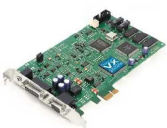
natural_image
Green printed circuit board with various electronic components and connectors (no visible text or symbols)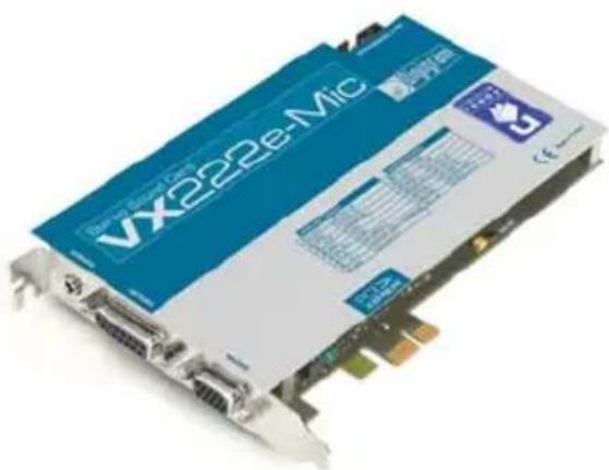
User manual
For technical support, please contact your system supplier

Digigram S.A.
82/84 Allée Galilée, 38330 Montbonnot-Saint-Martin, FRANCE
Tel: +33 (0)4 76 52 47 47• Fax: +33 (0) 4 76 52 18 44• E-mail: info@digigram.com
Digigram Inc.
2000 North 14th Street - Suite 530, Arlington, VA 22201, USA
Tel: +1 703 875 9100 • Fax: +1 703 875 9161 • E-mail: input@digigram.com
Digigram Asia Pte Ltd.
60 Albert Street - #19-11OG Albert Complex Singapore 189969, Singapore
Tel: +65 6291 2234 • Fax: +65 6291 3433 • E-mail: info_asia@digigram.com
\* \* \* \* \* \* \* \* \* \* \* \* \* \* \* \* \* \* \* \* \* \* \* \*
INFORMATION FOR THE USER....5
IMPORTANT NOTICE....5
CONTENTS OF THIS PACKAGE......6
FEATURES 6
VX222e & VX222e-Mic main hardware features 6
Additional hardware features VX222e-Mic 7
Main software features 7
HARDWARE REQUIREMENTS......8
Minimum requirements....8
Software requirements....8
Supported operating systems....8
HARDWARE INSTALLATION 8
Installing the card....8
Interrupt and memory address....8
SOFTWARE INSTALLATION......9
Standard installation under Windows XP, Server 2003, and Windows Vista....9
Parameterizing the ASIO and Wave drivers.... 11
Removing the driver under Windows XP and Server 2003....12
Removing the driver under Windows Vista 12
HOW TO CHECK THE INSTALLATION.... 12
THE 'DIGIGRAM HARDWARE SETTINGS' ('DHS')
CONTROL PANEL....14
SPECIFICATIONS......15
Configuration.... 15
Inputs 15
Additional inputs VX222e-Mic 16
Outputs.... 16
Connectors 16
Audio specifications.... 17
Analog audio performance.... 17
Sample rate converter performance.... 17
Analog mono microphone input features VX222e-Mic 18
AES42 microphone input features - VX222e-Mic 18
Development environments.... 19
APPENDICES 20
VX222e schematic diagram.... 20
VX222e-Mic schematic diagram 20
Layout....21
VX222e - analog cable diagram.... 22
VX222e-Mic - analog cable diagram.... 22
Wiring diagram - analog cable VX222e.... 23
Wiring diagram - analog cable VX222e.... 23
VX222e - digital cable with GPIOs 24
VX222e - digital cable without GPIOs 24
Wiring diagram - digital cable with GPIOs (VX222e) 25
Wiring Diagram - digital cable without GPIOs (VX222e) 25
VX222e-Mic - digital cable with GPIOs.... 26
VX222e-Mic - digital cable without GPIOs.... 26
Wiring diagram - digital cable with GPIOs (VX222e-Mic) 27
Wiring diagram - digital cable without GPIOs (VX222e-Mic) 27
VX222e cable pinout....28
VX222e-Mic cable pinout....28

Warning:
Electrostatic discharge (ESD) can damage several components on the board. To avoid such damage in handling the board, take the following precautions:
Bring the device and everything that contacts it to ground potential by providing a conductive surface and discharge paths. As a minimum, observe these precautions:
• Disconnect all power and signal sources.
- Place the device on a grounded conductive work surface.
• Ground yourself via a grounding wrist strap or by holding a grounded object.
• Ground any tool that will contact the device.
Due to the reduced length of the PCI EXPRESS ^TM bus connector and the resulting lack of mechanical stability, we strongly advise against transporting the card(s) installed in a computer, unless its chassis or case provides a dedicated support to keep the card securely in place in order to avoid physical damage.
Copyright 2007 – 2010 Digigram. All rights reserved.
No portion of this manual may be reproduced without prior written consent from Digigram. The copyright protection claimed here includes photocopying, translation and/or reformatting of the information contained in this manual.
While every effort has been made to ensure accuracy, Digigram is not responsible for errors and omissions, and reserves the right to make improvements or changes in the products and programs described without notice.
Digigram and the Digigram logo, VX222e and VX222e-Mic are registered trademarks or trademarks of Digigram S.A.. All other trademarks are property of their respective holders.
INFORMATION FOR THE USER
This device complies with part 15 of FCC rules. Operation is subject to the following two conditions: (1) This device may not cause harmful interference, and (2) This device must accept any interference received, including interference that may cause undesired operation.
This equipment has been tested and found to comply with the limits for a CLASS B digital device, pursuant to Part 15 of the FCC Rules. These limits are designed to provide reasonable protection against harmful interference in a residential installation. This equipment generates, uses, and can radiate radio frequency energy and, if not installed and used in accordance with the instructions contained in this data sheet, may cause harmful interference to radio and television communications. However, there is no guarantee that interference will not occur in a particular installation.
If this equipment does cause harmful interference to radio or television reception, which can be determined by turning the equipment off and on, the user is encouraged to try to correct the interference by one or more of the following measures:
* reorient or relocate the receiving antenna
* increase the separation between the equipment and the receiver
* connect the equipment into an outlet on a circuit different from that of the receiver
* consult the dealer or an experienced audio television technician.
Note: Connecting this device to peripheral devices that do not comply with CLASS B requirements or using an unshielded peripheral data cable could also result in harmful interference to radio or television reception. The user is cautioned that any changes or modifications not expressly approved by the party responsible for compliance could void the user's authority to operate this equipment. To ensure that the use of this product does not contribute to interference, it is necessary to use shielded I/O cables.
IMPORTANT NOTICE
This card has been tested and found to comply with the following standards:
• International: CISPR22 Class B.
• Europe: EMC 89/336/CEE (1992) specifications.
• United States: FCC Rules-Part 15-Class B (digital device).
In order to guarantee compliance with the above standards in an installation, the following must be done:
- the provided cable must not be modified.
• additional cables used must have their respective shield connected to each extremity.
CONTENTS OF THIS PACKAGE
Thank you for purchasing a Digigram VX sound card.
The package consists of the following components:
• a VX222e or VX222e-Mic sound card
• the User's Manual at hand.
The end user version additionally includes:
- two breakout cables (analog and digital)
- a CD-Rom with drivers, installation notices, FAQs, etc...
- a registration form
For the OEM version, the cables are available optionally.
FEATURES
VX222e and VX222e-Mic are audio cards for PCI EXPRESS™ (PCIe®) bus. They are in PCI EXPRESS™ x1 format and can thus be plugged into any PCIe® slot (x1, x2, x4, x8, x16, x32).
VX222e & VX222e-Mic main hardware features
- 2 balanced * analog mono line inputs, with software adjustable gain and a maximum input level of +24 dBu
- 2 servo-balanced ** analog mono line outputs, with software adjustable gain and a maximum output level of +24 dBu
- 1 AES/EBU *** stereo input The selection of the digital input for recording excludes the selection of the analog inputs. It is possible to use the signal on the digital input as reference clock.
- 1 AES/EBU *** stereo output
Always transmits the digital version of the analog outputs 1 and 2.
• 1 LTC (Linear Time Code) input - 1 mini jack headphone stereo output
This output is in parallel of the analog outputs 1 and 2.
• 2 General Purpose inputs and 2 outputs (GPIOs)
• Inter-card synchronization connector
Additional hardware features VX222e-Mic
• 1 analog microphone input with
- high-quality preamplifier
- switchable 48 V phantom power
- analog expander/compressor/limiter
This input is mixed with the two line inputs before A/D conversion.
• 1 AES/EBU Sync input
- The AES/EBU input is AES42 compatible (for connecting digital microphone) and features a hardware sample rate converter* (for details see chapter 'Specifications')
The two AES/EBU inputs on the VX222e-Mic allow:
- recording of a digital signal on the AES/EBU data input; this input is also used as source of synchronization with a digital clock
- recording of a digital signal on the AES/EBU data input, synchronized on a digital clock connected to the AES/EBU synchronization input;
- the synchronization of analog recording and playback on an AES/EBU clock connected to the AES/EBU Sync input.
The selection of the digital input excludes the selection of the analog inputs.
Main software features
- Real-time, simultaneous PCM record and playback (8, 16 and 24 bits), Float IEEE754 (with 24-bit fixed-point dynamic range)
- When using the np SDK, real-time on-board mixing of several PCM audio streams, direct monitoring, level adjustment, panning, cross-fades, punch-in/punch-out, scrubbing
- Possibility to control the parameters of the inputs and outputs (gains, mutes, 48 V switch, analog compressor-limiter-expander parameters), from the provided 'Digigram Hardware Settings' application, or from any application that addresses these controls
- 24-bit DSP effects in playback and recording: 3-band parametric equalizer plus Maximizer
- Low latency DirectSound, ASIO, and Wave ** drivers
Note: the HR Runtime package for Windows Vista does not include a Wave driver. In case your audio application explicitly requires a Wave interface, a Wave driver is available on request. In this case, please contact Digigram.
HARDWARE REQUIREMENTS
Minimum requirements
PC with one free PCI EXPRESS™ (PCIe®) slot (x1, x2, x4, x8, x16 or x32).
CPU power and memory required depend on the operating system and on the audio application used.
Software requirements
To use your VX222e or VX222e-Mic, install the driver from the HR Runtime package version 1.70 or higher. This package includes:
- a Digigram np driver enabling OEM applications to best capitalize on the boards
• a WDM DirectSound driver - a Wave driver * (32 bits, installation optional)
- an ASIO driver (32 bits, installation optional)
Supported operating systems
VX222e and VX222e-Mic cards run under Windows XP, Windows Vista, Windows Server 2008, and Windows 7.
HARDWARE INSTALLATION
Due to the reduced length of the PCI EXPRESS ^™ bus connector and the resulting lack of mechanical stability, we strongly advise against transporting the card(s) installed in a computer, unless its chassis or case provides a dedicated support to keep the card securely in place in order to avoid physical damage.
The card has to be installed in the computer prior to installing its driver.
Installing the card
Gently plug the card into a free PCIe ^® slot and press it down firmly to position it. Tighten the screw.
Interrupt and memory address
Hardware interrupt and addresses are automatically set up at start-up by the PCI PnP BIOS.
SOFTWARE INSTALLATION
Note: the installation of the software requires administrator rights on your computer
Please visit the Digigram web site at www.digigram.com for the most recent driver.
In case you run a specific application developed or installed by a Digigram partner, it might require the use of a specific driver version. In this case, make sure that the updated driver has been approved by your supplier.
Standard installation under Windows XP, Windows Server 2003, and Windows Vista
If the driver has been downloaded from our web site, it has to be expanded prior to the driver's installation as follows: double-click on the downloaded file (self-expanding). You can use the default destination location (Windows temporary folder) or select another directory.
Important note: this default procedure installs the 'Digigram Hardware Settings' control panel. This application allows the configuration of the hardware resources of Digigram cards for all audio applications. The DHS allows for instance to define the clock of the card, the input source, input and output analog and digital gain, Sample Rate Converters, digital output format, etc...
Please note that, with the DHS installed, controls available through the DirectSound control panel are limited to:
• Volume control for input and output
- Wave control
Under Windows XP, and Server 2003 you may also install the driver without installing the DHS control panel, and in this case more controls are available through the DirectSound control panel:
• Volume control for input
- Wave control
• Monitoring control
- Analog input level
- Digital input level
- Clock selection: AES Sync, AES1, Word Clock
• Digital output format: professional, consumer
To do so, install the driver with the command line: "setup x_topology" (not available under Windows Vista). For detailed information, please refer to the dedicated document on our web site.
- Shut down your computer and insert your VX card.
- Restart your computer.
- Click on Cancel if the "Found New Hardware" Wizard appears.
- Double-click on the HR Runtime vxx.msi/HR Runtime vxx.msi for Vista icon to launch the driver installation.
• A welcome message is displayed, click Next to continue. - The "License Agreement" window appears: read it, and click on "I accept the terms in the license agreement" to approve it.
- Do the same in the next window for Virtual PCX and PC Codec Legal Notice.
- In the “Custom Setup” window, the “Drivers for the HR boards” are displayed; by default, both WDM DirectSound and ASIO HR are installed.
To install the Wave driver ^* , select 'Wave'.
To be able to use your VX card through np, select the 'Digigram np' component option (or make sure that the np application explicitly sets the 'VX_FLAG' with PCXInitialize().
Next.
- In the "Ready to Install the Program Window", click on Install to start copying the files.
- Note: In case you use an unsigned driver version, the "Digital Signature Not Found" message may appear because a non-Microsoft software is about to be installed. Click on Continue in the "Hardware installation" window (Windows XP, Server 2003).
• Under Windows Vista:
Click Allow in the "User Account Control" window. Click Install in the "Windows Security" window.
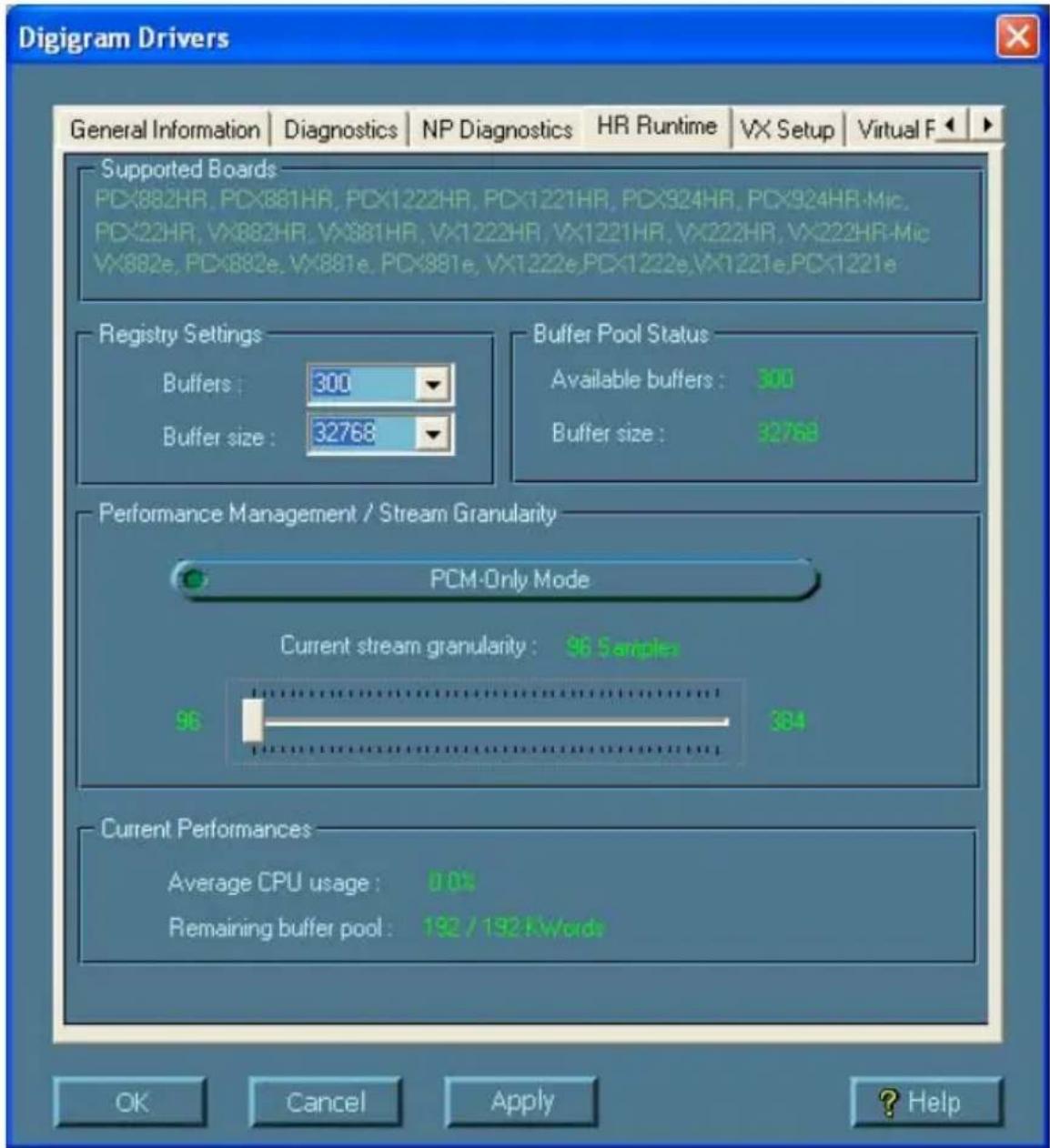
- In the "Digigram drivers" window, select the number and the size of buffers required by your applications. Click on Ok.
- Click Finish to complete the driver installation.
User Manual
Parameterizing the ASIO and Wave drivers
Note: for most current ASIO/Wave applications (e.g. Cubase, Nuendo, Winamp etc...) you have the choice between a 32-bit version and a 64-bit version when installing them under Windows ≥ Vista. For operation with your sound card, make sure to use the 32-bit version!
For all sound cards of the VX range, "PCM only" is the only operating mode, therefore this button is disabled in the Digigram control panel (CPL). (To access this control panel, go to
Removing the driver under Windows XP and Windows Server 2003
- Open the Windows Control Panel and double-click on the Add/Remove Software icon.
- Select Digigram HR Runtime ..., and Change/Remove.
- Select Remove in the "HR Runtime" window.
- Follow the instructions to finish the driver removal.
Removing the driver under Windows Vista, Windows Server 2008, and Windows 7
- Open the Windows Control Panel and double-click on the Programs and Features icon.
- Select "Digigram HR Runtime for Vista...", and Change/Remove.
- Select Remove in the HR Runtime window.
- Follow the instructions to finish removing the driver.
How to check the installation
Once the cards and the driver have been installed according to the procedure described in this manual, you can verify that the card is properly installed and works fine as follows:
- Menu
- The card is also visible via the np interface: go to
- In the “Digigram drivers” window, select the ‘General Information’ tab.
In the "Modules Information" window, you can see the HR Runtime modules that have been installed, and their versions. - In the “Digigram drivers” window, select the ‘Diagnostics’ tab.
You should see here the icons of the cards you have installed.
- If the card you have installed is listed:
• Right click on the icon of the card.
- Select 'Diagnostics', and Play Sine. This plays in loop a sine signal on the outputs of the card. You can also select Play file to play in loop a file of your choice (PCM only). If the playback is correct, the card is correctly installed and works.
- To stop the playback, right click on the card icon, and select Stop Activities.
- If the card is not displayed:
- Make sure that during the HR runtime installation the "Driver for the HR boards" has been selected in the "Select components" window.
- Make sure that the card is correctly inserted in the PCI slot, and screwed on the PC chassis.
- If necessary, uninstall the HR runtime package as described in this manual, and re-install it.
- If the Wave driver has been installed *:
- Go to menu
- If the ASIO driver has been installed:
- The card is visible from any ASIO application.
The 'Digigram Hardware Settings' ('DHS') control panel
Digigram hardware settings (DHS) is an application allowing to configure the hardware resources of Digigram cards for all audio applications using them. A resource being managed by the DHS application can not be modified by any other applications. To enable an audio application to modify a Digigram card resource, this resource must not be managed by the DHS.
Note: As soon as a resource of a card is managed by the DHS, the clock selection of this card MUST be defined in the DHS.
The DHS allows to:
- Select the clock the card uses
- Select the input source
• Set analog and digital gains of an input
- Enable Sample Rate Converters of an input
- Select the input monitored on an output
- Set the monitoring gains
- Set the analog and digital gains of an output
- Define the digital output format
For help on how to use this control panel, please refer to its on-line help.
SPECIFICATIONS
Configuration
| VX222e VX222e-Mic | ||
| Bus/Format | PCI EXPRESSTM (PCIe®) x1(x2, x4, x8, x16, x32 compatible) | |
| Digital Signal Processor Motorola 56303 at 100 MHz | ||
| RAM 128 kWords 512 kWords | ||
| Size 168 mm x 99 mm x 20 mm | ||
| Power requirements(+3.3V/ +12V) | 1 A / 0.2 A | 1.3 A* / 0,22 A |
| Operating:temp / humidity(non-condensing) | 0°C / +50°C • 5% / 90% | |
| Storage: temp / humidity(non-condensing) | -5°C / +70°C • 0% / 95% | |
Inputs
| VX222e VX22 | 2e-Mic | |
| Analog line inputs (mono) | 2 balanced** | 2 balanced** |
| Maximum input level/impedance | +24 dBu / <10 kΩ | +24 dBu / >10 kΩ |
| Digital inputs (stereo) | 1 AES/EBU*** | cf. separate table |
| Programmable input gain | analog: from -94 dB to +16 dB⊗digital: from -110 dB to +18 dB | |
| Other inputs | 2 GPI (dry contact),LTC | |
| AES11 synchronization Yes | ||
Additional inputs VX222e-Mic
| Microphone input | 1 professional mono with- high-quality preamplifier- switchable 48 V phantom power- analog expander/compressor/limiterThis input is mixed with the two line inputs before A/D conversion. |
| Digital input (stereo) * | 1 AES/EBU, AES42 compatible- with hardware sample rate converter (SRC)- supplying 10 V to feed a digital microphone- allowing remote microphone control |
| Other inputs** | AES/EBU Sync (up to 200 kHz) |
Outputs
| VX222e VX222e-Mic | ||
| Analog line outputs (mono) | 2 servo-balanced*** | |
| Maximum output level / impedance | +24 dBu / < 100 Ω | |
| Digital outputs (stereo) 1 AES/EBU, up to 200 kHz | ||
| Programmable output gain | analog: from -24 dB to +24 dBdigital: from -110 dB à +18 dB | |
| Other outputs | 1 stereo headphone output (600 Ω)2 GPO (relay, 0.5 A, 48 VCC) | |
Connectors
| VX222e VX222e-Mic | ||
| Internal connector Inter board synchronization | ||
| External connectors | 15-pin Sub-D for analog I/Os15-pin HD Sub-D for digital I/Os, Sync., and GPIOMini jack headphone stereo output (3,5 mm TRS female jack) | |
Audio specifications
| VX222e VX222e-Mic | ||
| Sampling frequencies available | Programmable from 8 to 192 kHz | |
| A/D and D/A converter resolution | 24 bits 24 bits | |
| Supported audio formats PCM | (8, 16, 24 bits), Float IEEE754 | |
Analog audio performance
Measurements done at Fs=48 kHz unless stated otherwise, with filter on the 22 Hz-22 kHz range
| VX222e VX22 | 2e-Mic | |
| Frequency response (record + play) | at 48 kHz: 20 Hz - 20 kHz: +0 /-0.3 dB at 96 kHz: 20 Hz - 40 kHz: +0 /-0.4 dB at 192 kHz: 20 Hz - 80 kHz: +0 /-1.1 dB | |
| Channel phase difference: 20/20kHz | <0.2°/2° | |
| Dynamic range (A-weighted) | Analog In: >104 dB Analog Out: >106 dB | |
| THD + noise 1 kHz at -2 dBfs | Analog In: <-97 dB Analog Out: <-95 dB | |
| Crosstalk (Analog in or out) | 1 kHz at 24 dBu: <-115 dB 15 kHz at 24 dBu: <-100 dB | |
Sample rate converter performance
| VX222e-Mic | |
| Maximum frequency 192 kHz | |
| Frequency ratio from 1:8 to 7,5:1 | |
| THD + noise 1 kHz at -2 dBfs | <-130 dB |
Analog mono microphone input features VX222e-Mic
| Power supply switchable 48 V phantom power | |
| Programmable mic gain 0 to 66 dB in 0.5 dB steps | |
| Maximum input level/impedance | +10 dBu / >10 kΩ |
| Equivalent Input Noise, A/D-D/A at 48kHz, G=60 dB | <-125 dBu |
| Programmable noise-gate threshold | -52 dB, -42 dB, -32 dB |
| Programmable compressor/limiter threshold | from -26 dB to 0 dB |
| Programmable compressor ratio | 1, 1.2, 1.5, 1.8, 2, 2.5, 3, 3.5, 4, 4.5 |
| Programmable compressor/limiter gain | from 0 to 16 dB |
| Limiter ratio | 15:1 |
| Compressor/limiter release time | 150 ms |
| Management of line and mic inputs | Mixed together before A/D, with independent level and mute controls |
AES42 microphone input features - VX222e-Mic
| Power supply 10 V min / 250 mA | max |
| Remote control Yes | |
| Supported synchronization | Operational mode 1(the microphone generates its own clock) |
Development environments
| VX222e | VX222e-Mic | |
| Digigram management np $DK (HR runtime, PCM only) | ||
| Other management | Wave*, ASIO, DirectSound (all PCM only) | |
| Supported operating systems | Windows XP, Windows Vista, Windows Server 2008, and Windows 7 | |
| Main on-board processing features (with np SDK) | PCM play, rec, Float IEEE754, direct monitoring, real-time mixing, level adjustment, panning, cross-fade, punch-in/punch-out, scrubbing, 3-band parametric equalizer plus Maximizer | |
APPENDICES
VX222e schematic diagram
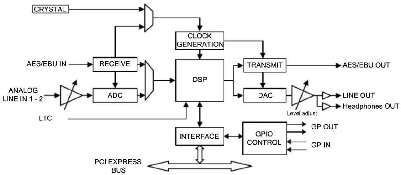
flowchart
graph TD
    A["CRYSTAL"] --> B["CLOCK GENERATION"]
    C["AES/EBU IN"] --> D["RECEIVE"]
    E["ANALOG LINE IN 1-2"] --> F["ADC"]
    G["LTC"] --> H["AND Gate"]
    H --> D
    D --> I["DSP"]
    I --> J["TRANSMIT"]
    J --> K["AES/EBU OUT"]
    I --> L["DAC"]
    L --> M["Level adjust"]
    M --> N["LINE OUT"]
    M --> O["Headphones OUT"]
    I --> P["INTERFACE"]
    P --> Q["GPIO CONTROL"]
    Q --> R["GP OUT"]
    Q --> S["GP IN"]
    P <--> T["PCI EXPRESS BUS"]
    T <--> U["AND Gate"]
VX222e-Mic schematic diagram
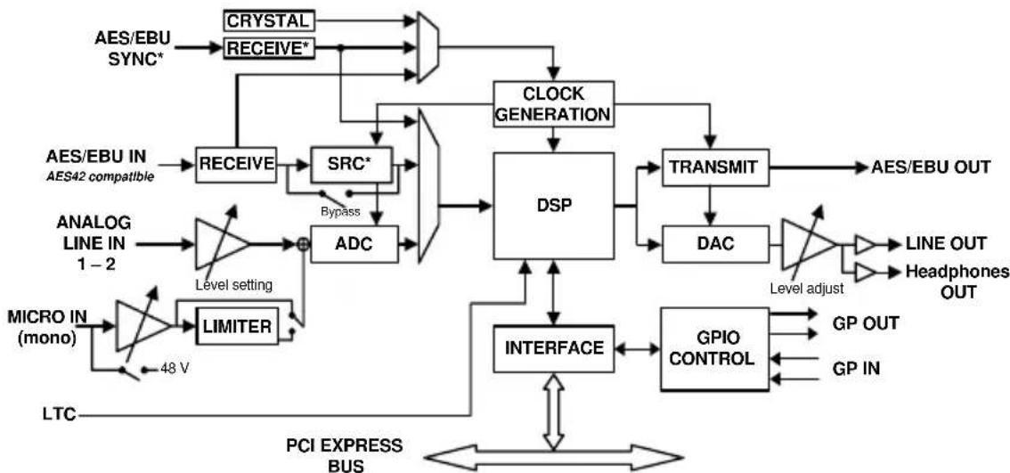
flowchart
graph TD
    A["LTC"] --> B["Micro IN (mono)"]
    B --> C["LIMITER"]
    C --> D["Level setting"]
    D --> E["ADC"]
    E --> F["DSP"]
    F --> G["TRANSMIT"]
    G --> H["AES/EBU OUT"]
    F --> I["TRANSMIT"]
    I --> J["DAC"]
    J --> K["Level adjust"]
    K --> L["LINE OUT"]
    K --> M["Headphones OUT"]
    F --> N["INTERFACE"]
    N --> O["GPIO CONTROL"]
    O --> P["GP OUT"]
    O --> Q["GP IN"]
    F --> R["CLOCK GENERATION"]
    R --> S["CRYSTAL"]
    S --> T["RECEIVE*"]
    T --> U["ASYS/CYSTAL SYNC*"]
    U --> V["RECEIVE"]
    V --> W["SRC*"]
    W --> X["Bypass"]
    X --> Y["ADC"]
    Y --> Z["DSP"]
    Z --> AA["TRANSMIT"]
    AA --> AB["DISP"]
    AB --> AC["TYPE/TYPE INPUT"]
    AC --> AD["PCI EXPRESS BUS"]
    AD --> AE["48 V"]
    AE --> B
*on request on VX222e
Layout
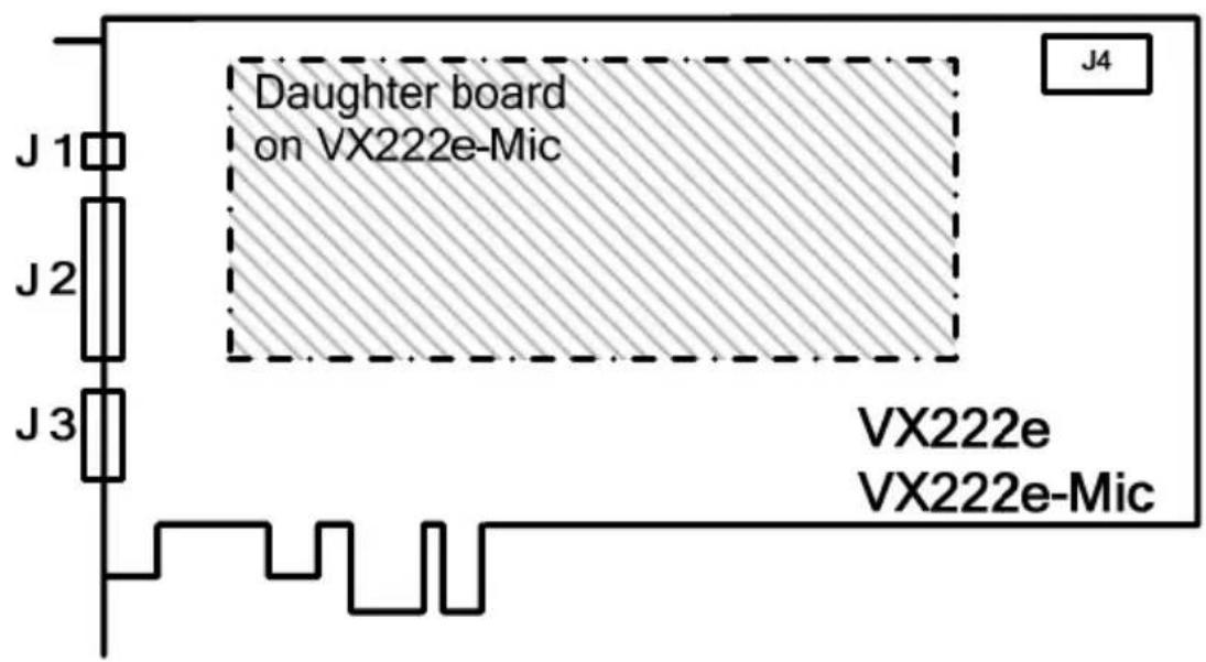
J1: Headphone connector:
(3.5 mm TRS female jack)
| Contact Signal | |
| Sleeve | Ground |
| Tip | Left |
| Ring | Right |
channel channel
J2: Analog cable
J3: Digital cable
J4: Inter-card synchronization connector
VX222e - analog cable diagram
Analog cable delivered by Digigram:
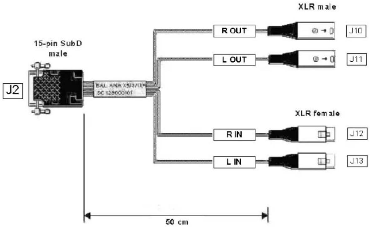
flowchart
graph TD
    A["15-pin SubD male"] --> B["8AL ANA X5/3/1X SC 12300010T"]
    B --> C["R OUT"]
    B --> D["L OUT"]
    B --> E["R IN"]
    B --> F["L IN"]
    C --> G["XLR male"]
    D --> H["XLR female"]
    E --> I["XLR male"]
    F --> J["XLR female"]
    style A fill:#f9f,stroke:#333
    style B fill:#ccf,stroke:#333
    style C fill:#cfc,stroke:#333
    style D fill:#cfc,stroke:#333
    style E fill:#cfc,stroke:#333
    style F fill:#cfc,stroke:#333
    style G fill:#fcc,stroke:#333
    style H fill:#fcc,stroke:#333
    style I fill:#fcc,stroke:#333
    style J fill:#fcc,stroke:#333
VX222e-Mic - analog cable diagram
Analog cable delivered by Digigram:
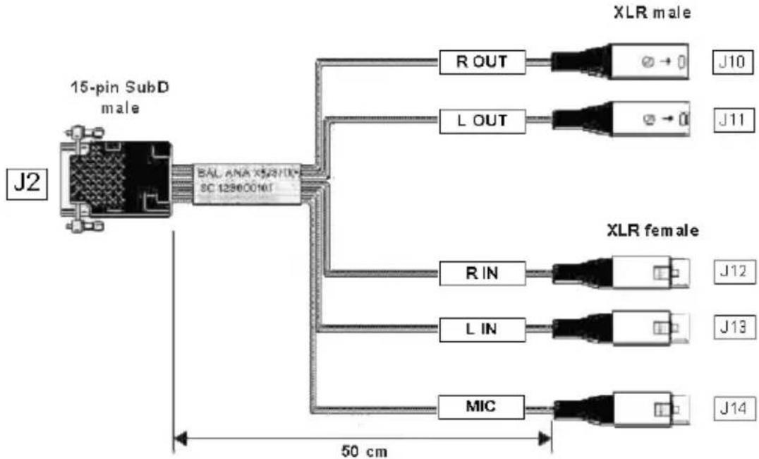
flowchart
graph TD
    A["15-pin SubD male"] --> B["BAL ANA X52310X SC 12860010T"]
    B --> C["R OUT"]
    B --> D["L OUT"]
    B --> E["R IN"]
    B --> F["L IN"]
    B --> G["MIC"]
    C --> H["XLR male"]
    D --> I["XLR female"]
    E --> J["XLR male"]
    F --> K["XLR female"]
    G --> L["XLR male"]
    G --> M["XLR female"]
    style A fill:#f9f,stroke:#333
    style B fill:#ccf,stroke:#333
    style C fill:#cfc,stroke:#333
    style D fill:#cfc,stroke:#333
    style E fill:#cfc,stroke:#333
    style F fill:#cfc,stroke:#333
    style G fill:#cfc,stroke:#333
    style H fill:#fcc,stroke:#333
    style I fill:#fcc,stroke:#333
    style J fill:#fcc,stroke:#333
    style K fill:#fcc,stroke:#333
    style L fill:#fcc,stroke:#333
    style M fill:#fcc,stroke:#333
Wiring diagram - analog cable VX222e
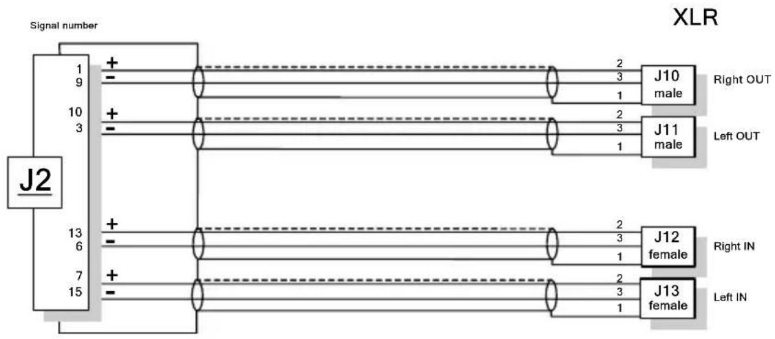
flowchart
graph TD
    A["Signal number"] --> B["J2"]
    B --> C["1 9 +"]
    B --> D["10 3 +"]
    B --> E["13 6 +"]
    B --> F["7 15 +"]
    C --> G["J10 male"]
    D --> H["J11 male"]
    E --> I["J12 female"]
    F --> J["J13 female"]
    G --> K["Right OUT"]
    H --> L["Left OUT"]
    I --> M["Right IN"]
    J --> N["Left IN"]
Wiring diagram - analog cable VX222e
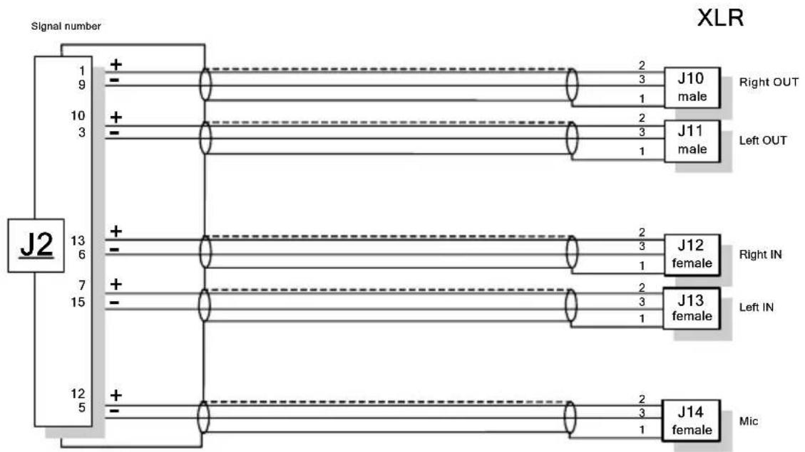
flowchart
graph TD
    A["Signal number"] --> B["J2"]
    B --> C["19"]
    B --> D["103"]
    B --> E["136"]
    B --> F["715"]
    B --> G["125"]
    C --> H["+"]
    D --> I["+"]
    E --> J["+"]
    F --> K["+"]
    G --> L["+"]
    H --> M["J10 male Right OUT"]
    I --> N["J11 male Left OUT"]
    J --> O["J12 female Right IN"]
    K --> P["J13 female Left IN"]
    L --> Q["J14 female Mic"]
VX222e - digital cable with GPIOs
Schematic diagram of the cable delivered by Digigram*:

flowchart
graph TD
    A["SubD HD 15pts Male<br>Male 15pts SubD HD"] --> B["J3"]
    B --> C["OUT: 48 VDC / 0.5 AMAX<br>IN: Dry contacts only : 5 V/5 mA<br>Delivered by the card"]
    C --> D["OUT: 6 IN1, OUT2 IN2, OUT1 IN3, OUT2 IN4, OUT1 IN5"]
    D --> E["Warning"]
    E --> F["XLR Female"]
    E --> G["XLR Male"]
    E --> H["RCA female"]
    E --> I["LTC IN"]
    I --> J["50 cm"]
    K["SubD 9-pin Female"] --> L["J15"]
    M["XLR Female"] --> N["J16"]
    O["XLR Male"] --> P["J17"]
    Q["RCA Female"] --> R["J18"]
VX222e - digital cable without GPIOs
Schematic diagram of the cable delivered by Digigram*:
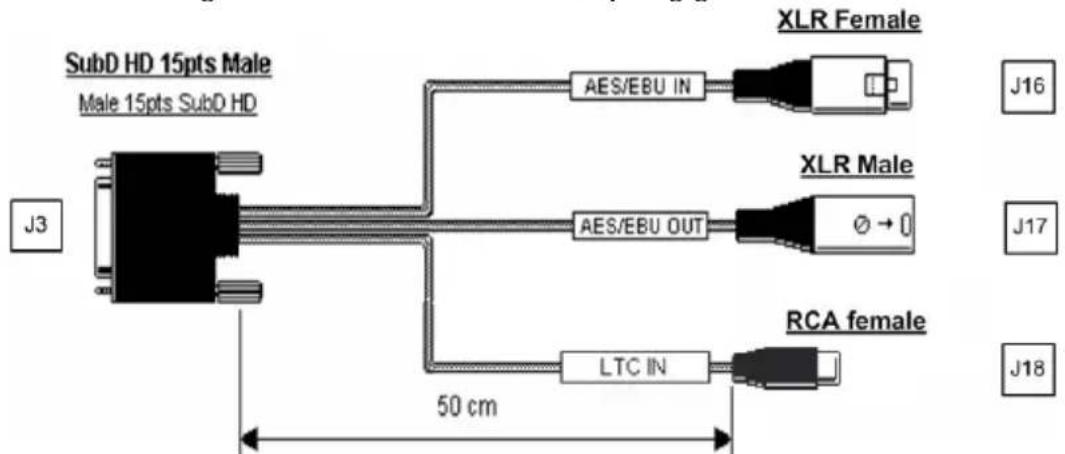
flowchart
graph LR
    A["SubD HD 15pts Male<br>Male 15pts SubD HD"] --> B["AES/EBU IN"]
    A --> C["AES/EBU OUT"]
    A --> D["LTC IN"]
    B --> E["XLR Female"]
    C --> F["XLR Male"]
    D --> G["RCA female"]
    style A fill:#f9f,stroke:#333
    style B fill:#ccf,stroke:#333
    style C fill:#ccf,stroke:#333
    style D fill:#ccf,stroke:#333
* Your cable may look different if it is not a Digigram cable.
User Manual
Wiring diagram - digital cable with GPIOs (VX222e)
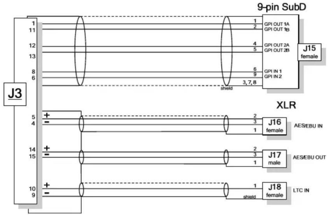
flowchart
graph TD
    subgraph J3
        A["1"] --> B["2"]
        C["11"] --> D["4"]
        E["12"] --> F["5"]
        G["13"] --> H["6"]
        I["8"] --> J["9"]
        K["6"] --> L["shield"]
    end
    subgraph XLR
        M["5"] --> N["+"]
        O["4"] --> P["-"]
        Q["14"] --> R["+"]
        S["15"] --> T["-"]
        U["10"] --> V["+"]
        W["9"] --> X["shield"]
    end
    subgraph 9-pin SubD
        Y["GPI OUT 1A\nGPI OUT 1B"] --> Z["J15 female"]
        AA["GPI OUT 2A\nGPI OUT 2B"] --> AB["J15 female"]
        AC["GPI IN 1\nGPI IN 2"] --> AD["J15 female"]
    end
    subgraph XLR
        AE["J16 female"] --> AF["AES/EBU IN"]
        AG["J17 male"] --> AH["AES/EBU OUT"]
        AI["J18 female"] --> AJ["LTC IN"]
    end
Wiring Diagram – digital cable without GPIOs (VX222e)
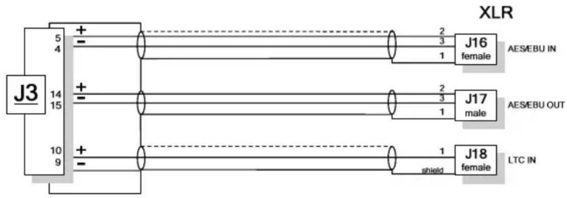
flowchart
graph TD
    A["J3"] -->|5 4| B["+"]
    A -->|10 9| C["+"]
    B --> D["J16 female"]
    C --> E["J17 male"]
    D --> F["AES/EBU IN"]
    E --> G["AES/EBU OUT"]
    H["J18 female"] --> I["LTC IN"]
    style A fill:#f9f,stroke:#333
    style B fill:#ccf,stroke:#333
    style C fill:#ccf,stroke:#333
    style D fill:#cfc,stroke:#333
    style E fill:#cfc,stroke:#333
    style F fill:#fcc,stroke:#333
    style G fill:#fcc,stroke:#333
    style H fill:#cff,stroke:#333
Note: digital cable for VX222e with additional AES/EBU Sync input on special request.
VX222e-Mic - digital cable with GPIOs
Schematic diagram of the cable delivered by Digigram*:
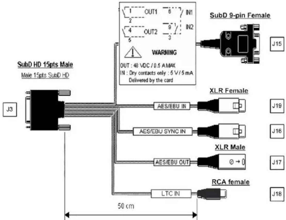
flowchart
graph TD
    A["SubD HD 15pts Male<br>Male 15pts SubD HD"] --> B["Warning"]
    B --> C["SubD 9-pin Female"]
    B --> D["XLR Female"]
    B --> E["XLR Male"]
    B --> F["RCA female"]
    A --> G["J3"]
    A --> H["LTC IN"]
    A --> I["AES/EBU OUT"]
    A --> J["AES/EBU SYNC IN"]
    A --> K["AES/EBU IN"]
    A --> L["OUT: 48 VDC / 0.5 AMAX<br>IN: Dry contacts only : 5 V/5 mA<br>Delivered by the card"]
    style A fill:#f9f,stroke:#333
    style B fill:#ccf,stroke:#333
    style C fill:#cfc,stroke:#333
    style D fill:#fcc,stroke:#333
    style E fill:#cff,stroke:#333
    style F fill:#ffc,stroke:#333
    style G fill:#fff,stroke:#333
    style H fill:#fff,stroke:#333
    style I fill:#fff,stroke:#333
    style J fill:#fff,stroke:#333
    style K fill:#fff,stroke:#333
    style L fill:#fff,stroke:#333
VX222e-Mic - digital cable without GPIOs
Schematic diagram of the cable delivered by Digigram*:
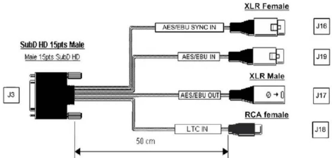
flowchart
graph LR
    A["SubD HD 15pts Male<br>Male 15pts SubD HD"] --> B["AES/EBU SYNC IN"]
    A --> C["AES/EBU IN"]
    A --> D["AES/EBU OUT"]
    A --> E["LTC IN"]
    B --> F["XLR Female"]
    C --> G["XLR Male"]
    D --> H["RCA female"]
    E --> I["J16"]
    E --> J["J19"]
    E --> K["J17"]
    E --> L["J18"]
    A --> M["50 cm"]
* Your cable may look different if it is not a Digigram cable.
Wiring diagram - digital cable with GPIOs (VX222e-Mic)

flowchart
graph TD
    subgraph 9-pin SubD
        A["1"] --> B["3"]
        C["11"] --> D["2"]
        E["12"] --> F["4"]
        G["13"] --> H["5"]
        I["8"] --> J["6"]
        K["6"] --> L["3, 7, 8"]
        M["J15 female"] --> N["GPI OUT 1A GPI OUT 1B"]
        O["J15 female"] --> P["GPI OUT 2A GPI OUT 2B"]
        Q["J15 female"] --> R["GPI IN 1 GPI IN 2"]
    end

    subgraph XLR
        S["J3"] --> T["3"]
        U["J3"] --> V["2"]
        W["J3"] --> X["5"]
        Y["J3"] --> Z["4"]
        AA["J3"] --> AB["14"]
        AC["J3"] --> AD["15"]
        AE["J3"] --> AF["10"]
        AG["J3"] --> AH["9"]
        AI["J19 female"] --> AJ["AES/EBU IN"]
        AK["J16 female"] --> AL["AES/EBU SYNC IN"]
        AM["J17 male"] --> AN["AES/EBU OUT"]
        AO["J18 female"] --> AP["LTC IN"]
    end
    J3 -->|shield| XLR
    J3 -->|shield| XLR
    J3 -->|shield| XLR
    style 9-pin SubD fill:#f9f,stroke:#333
    style XLR fill:#ccf,stroke:#333
Wiring diagram - digital cable without GPIOs (VX222e-Mic)
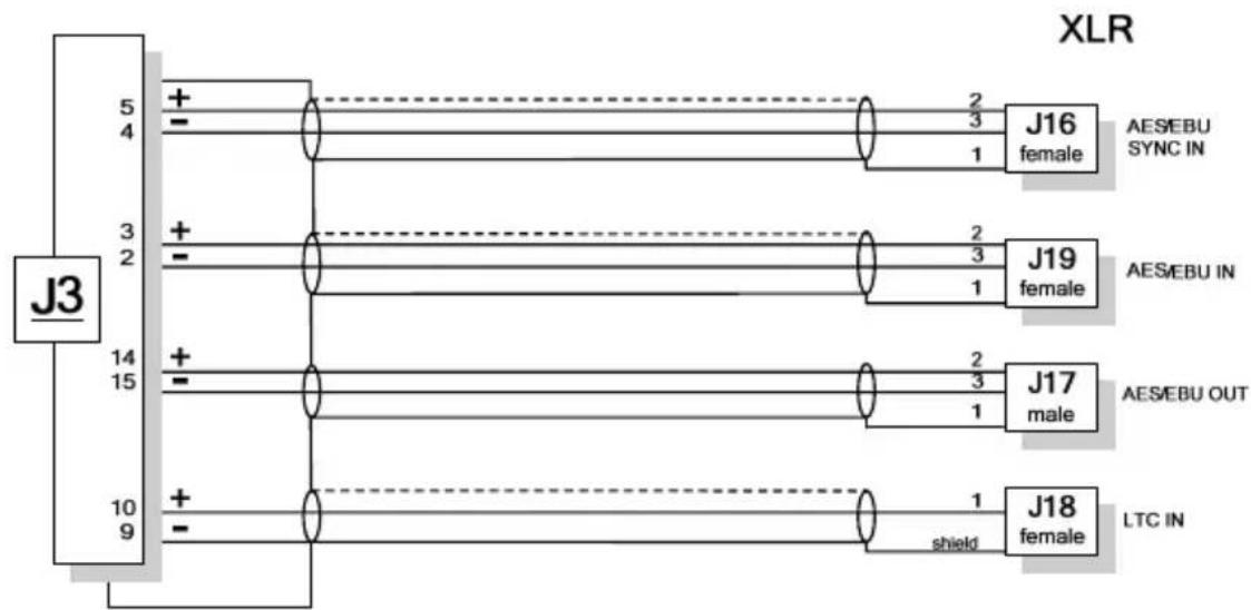
flowchart
graph TD
    A["J3"] --> B["5 4"]
    A --> C["3 2"]
    A --> D["14 15"]
    A --> E["10 9"]
    B --> F["+"]
    C --> G["+"]
    D --> H["+"]
    E --> I["+"]
    F --> J["J16 female"]
    G --> K["J19 female"]
    H --> L["J17 male"]
    I --> M["J18 female"]
    J --> N["AES/EBU SYNC IN"]
    K --> O["AES/EBU IN"]
    L --> P["AES/EBU OUT"]
    M --> Q["LTC IN"]
VX222e cable pinout
| Pin # | ANALOG DIGITAL | |
| 1 | R OUT + GPO OUT 1A | |
| 2 | GND | NC |
| 3 | L OUT - NC | |
| 4 | GND AES/EBU IN - | |
| 5 | NC AES/EBU IN + | |
| 6 | R IN - GPI INPUT 2 | |
| 7 | L IN + GND/GPO COMMON INPUT | |
| 8 | GND GPI INPUT 1 | |
| 9 | R OUT - GND | |
| 10 | L OUT + LTC IN | |
| 11 | GND GPO OUT 1B | |
| 12 | NC GPO OUT 2A | |
| 13 | R IN + GPO OUT 2B | |
| 14 | GND AES/EBU OUT + | |
| 15 | L IN - AES/EBU OUT - | |
VX222e-Mic cable pinout
| Pin # | ANALOG DIGITAL |
| 1 | R OUT + GPO OUT 1A |
| 2 | GND AES/EBU IN - |
| 3 | L OUT - AES/EBU IN + |
| 4 | GND AES/EBU SYNC IN - |
| 5 | MIC IN AES/EBU SYNC IN + |
| 6 | R IN - GPI INPUT 2 |
| 7 | L IN + GND/GPI INPUT COMMON |
| 8 | GND GPI INPUT 1 |
| 9 | R OUT - GND |
| 10 | L OUT + LTC IN |
| 11 | GND GPI OUT 1B |
| 12 | MIC IN + GPI OUT 2A |
| 13 | R IN + GPI OUT 2B |
| 14 | GND AES/EBU OUT + |
| 15 | L IN - AES/EBU OUT - |
- For technical support, please contact your system supplier
- Digigram S.A.
- Digigram Inc.
- Digigram Asia Pte Ltd.
- \* \* \* \* \* \* \* \* \* \* \* \* \* \* \* \* \* \* \* \* \* \* \* \*
- INFORMATION FOR THE USER....5
- IMPORTANT NOTICE....5
- CONTENTS OF THIS PACKAGE......6
- FEATURES 6
- HARDWARE REQUIREMENTS......8
- HARDWARE INSTALLATION 8
- SOFTWARE INSTALLATION......9
- HOW TO CHECK THE INSTALLATION.... 12
- THE 'DIGIGRAM HARDWARE SETTINGS' ('DHS')
- CONTROL PANEL....14
- SPECIFICATIONS......15
- APPENDICES 20
- Warning:
- INFORMATION FOR THE USER
- IMPORTANT NOTICE
- CONTENTS OF THIS PACKAGE
- FEATURES
- VX222e & VX222e-Mic main hardware features
- Additional hardware features VX222e-Mic
- Main software features
- HARDWARE REQUIREMENTS
- Minimum requirements
- Software requirements
- Supported operating systems
- HARDWARE INSTALLATION
- Installing the card
- Interrupt and memory address
- SOFTWARE INSTALLATION
- Standard installation under Windows XP, Windows Server 2003, and Windows Vista
- User Manual
- Parameterizing the ASIO and Wave drivers
- Removing the driver under Windows XP and Windows Server 2003
- Removing the driver under Windows Vista, Windows Server 2008, and Windows 7
- How to check the installation
- The 'Digigram Hardware Settings' ('DHS') control panel
- The DHS allows to:
- SPECIFICATIONS
- Analog audio performance
- APPENDICES
- VX222e - analog cable diagram
- VX222e-Mic - analog cable diagram
- VX222e - digital cable with GPIOs
- VX222e - digital cable without GPIOs
- VX222e-Mic - digital cable with GPIOs
- VX222e-Mic - digital cable without GPIOs
Brand : Digigram
Model : VX222e
Category : Hi-Fi