
FreeWave IR Commander - Remote control Vello - Free user manual and instructions
Find the device manual for free FreeWave IR Commander Vello in PDF.


| Product Type | Remote Flash Commander |
| Brand | Vello |
| Model | FreeWave IR Commander |
| Compatibility | Nikon i-TTL system |
| Transmission Method | Infrared (IR) |
| Number of Channels | 4 (1-4) |
| Number of Groups | 3 (A, B, C) |
| Flash Control Modes | i-TTL, Auto Aperture (AA), Manual, Stroboscopic (Repeating) |
| TTL Exposure Compensation | ±3 EV in 1/3-stop increments |
| High-Speed Sync | Up to 1/8000 sec (with compatible flashes) |
| Stroboscopic Frequency | 1-100 Hz |
| Stroboscopic Flash Count | 1-24 flashes per frame |
| Autofocus Assist | Red AF-assist beam |
| Modeling Light | Yes (via camera Depth of Field Preview button) |
| Power Source | 2x AA batteries (same type and age) |
| Dimensions (W x H x D) | 2.1 x 3.0 x 3.3 in (5.3 x 7.6 x 8.3 cm) |
| Weight (approx.) | 3.5 oz (99 g) |
| Mount Type | Hot shoe with locking wheel |
| Rotation | 180° for line-of-sight positioning |
| Display | Blue backlit LCD |
| Included Accessories | Drawstring pouch, user manual |
| Maintenance | Clean metal contacts with isopropyl alcohol; keep dry |
| Safety | Keep away from water, flammable substances; do not disassemble |
Frequently Asked Questions - FreeWave IR Commander Vello
User questions about FreeWave IR Commander Vello
0 question about this device. Answer the ones you know or ask your own.
Ask a new question about this device
Download the instructions for your Remote control in PDF format for free! Find your manual FreeWave IR Commander - Vello and take your electronic device back in hand. On this page are published all the documents necessary for the use of your device. FreeWave IR Commander by Vello.
USER MANUAL FreeWave IR Commander Vello
THANK YOU FOR CHOOSING VELLO
The Vello FWIRC-N FreeWave IR Commander is the nexus of your wireless flash setup, enabling you to set and control all functions of your wireless slave flash units. Equipped with an infrared transmitter, it provides the freedom of remote IR triggering for an unlimited number of flashes, and full compatibility with Nikon's i-TTL metering system for total wireless
TTL control. It also offers high-speed sync with compatible flashes, allowing you to use shutter speeds higher than your camera's top flash sync speed. Three groups and four independent channels deliver enhanced wireless operation, even in busy environments, and the Commander itself can be rotated atop your camera for easy line-of-sight positioning.
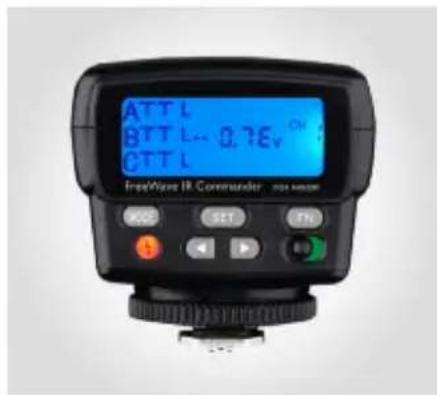
TABLE OF CONTENTS
Precautions....4
Key Features......6
Overview 7
Compatible Devices....8
Installing Batteries......8
Setting Up Slave Flash Units 9
Mounting the FreeWave
IR Commander....11
Turning On the FreeWave IR
Commander 12
Selecting Channels....14
About Flash Groups....15
i-TTL Mode....16
Auto Aperture Mode....18
Manual Mode....20
S1 Optical Slave Mode 22
Factory Reset......22
Advanced Features 23
High-Speed Sync Mode....23
Repeating (Stroboscopic) Mode 23
The Modeling Light 25
Autofocus Assist 25
Flash Exposure Bracketing 26
FlashValueLock 26
Specifications 27
Troubleshooting....28
PRECAUTIONS
- Please read and follow these instructions and keep this manual in a safe place.
- Keep this product away from water, moisture, and any flammable gases or liquids.
- Do not attempt to disassemble or repair this product.
-
Use only parts provided by the manufacturer.
• Make sure that this product is intact and that there are no missing parts. -
Should this product sustain physical damage, do not touch any exposed interior metal parts. If touched, they may generate an electric shock or cause a malfunction. Promptly remove the batteries and contact Vello Customer Service.
- If you detect excessive heat, smoke, or a burning smell coming from this product, immediately cease operation and remove the batteries to prevent the product from igniting or melting.
- Do not aim the transmitter directly in the eyes of any person or animal.
• Always install AA batteries of the same type and age. Do not combine different types or old and new batteries.
- Dispose of used or damaged batteries according to local regulations.
• Install the batteries in the proper orientation, as indicated by the markings in the battery carrier.
- Remove all batteries from this product before long-term storage.
- Keep this product away from children.
- Keep the metal contacts in the battery compartment clean and free of corrosion and dirt. Do not touch them with your fingers. Corrosive elements on the contacts can damage this product and prevent it from functioning properly. Contacts may be cleaned with isopropyl alcohol on a cotton swab.
- Handle this product with care.
-
To avoid damage to this product, be careful not to overtighten or improperly thread any of the threaded fittings.
-
Do not clean this product with agents containing corrosive or flammable substances.
- All images are for illustrative purposes only.
KEY FEATURES
180° rotation: Pivots to achieve IR line of sight.
Wireless i-TTL (intelligent through-the-lens): Makes full use of your flashes' built-in i-TTL technology.
TTL exposure compensation: Enables adjustment of TTL exposure by ±3 EV with fine-tuning by 1/3 of a stop.
AA mode: Uses your flash's built-in sensor to automatically set the appropriate power output.
Manual mode: Can manually adjust power output in 1/3 increments.
Standby mode: Reduces power consumption.
Internal memory: Remembers settings when turned off.
High-speed sync: Allows flash synchronization up to 1/8000 of a second.
Stroboscopic mode: Fires the flash multiple times in quick succession during a single exposure.
Modeling light: Gives the appearance of a continuous light to simulate the direction of light.
Flash Exposure Bracketing: Allows continuous pictures while automatically changing flash exposure compensation.
Flash value lock: Locks the flash output level that's optimal for specific elements of the scene.
OVERVIEW
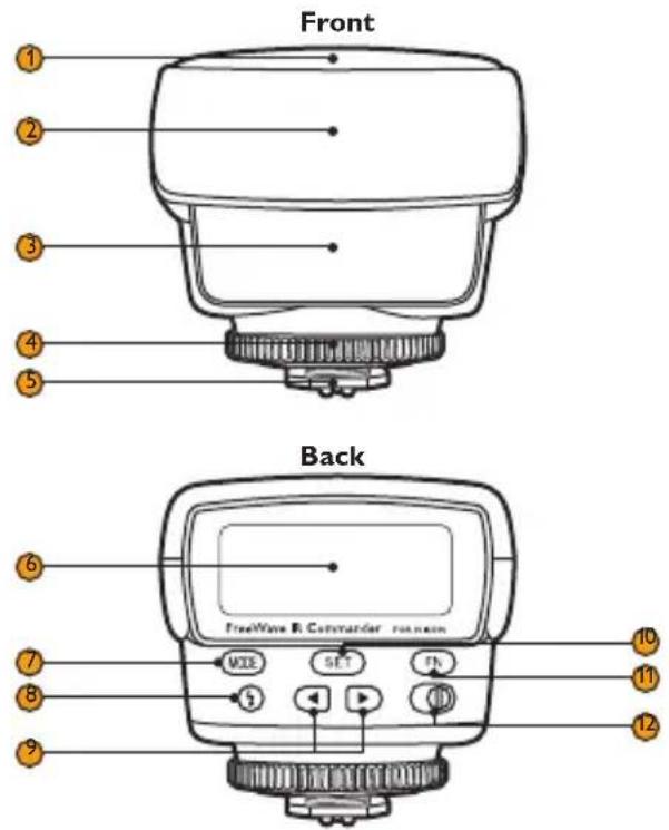
- Battery chamber
- AF-assist light
- Transmitter
- Locking wheel
- Mounting foot
- LCD
- Mode button
- Test button/flash ready light [§]
- Navigation buttons [◀▶]
- Set button
- FN button
- Power switch
Also Included
- Drawstring pouch
- User manual
COMPATIBLE DEVICES INSTALLING BATTERIES
The Vello FWIRC-N FreeWave IR Commander is compatible with Nikon's i-TTL (intelligent through-the-lens) system. To make full use of the FreeWave IR Commander, we recommend using i-TTL-capable hot-shoe flashes that are fully compatible with your camera's i-TTL system.
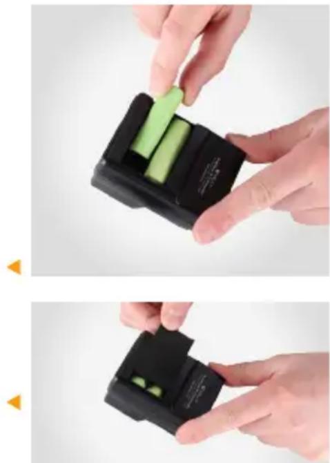
The FreeWave IR Commander is powered by two AA batteries. To install batteries, make sure the device is turned off and follow these steps:
- Press and slide the battery compartment cover in the direction of the arrow to open.
- Insert batteries in the orientations indicated by the illustrations inside the compartment.
- Close the battery compartment cover by pressing and sliding it in the opposite direction of the arrow on the cover.
SETTING UP SLAVE FLASH UNITS
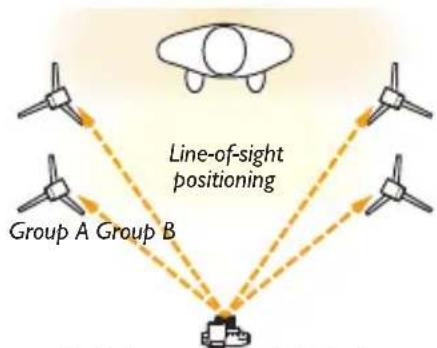
You can create a sophisticated lighting setup by positioning slave flash units individually or in groups to function as main, fill, accent, and other lights. Setting your power outputs to achieve specific looks gives you a professional level of creative control.
flowchart
graph TD
    A["Group A"] --> D["Line-of-sight positioning"]
    B["Group B"] --> D
    C["Top Object"] --> D
    style A fill:#f9f,stroke:#333
    style B fill:#f9f,stroke:#333
    style C fill:#f9f,stroke:#333
    style D fill:#ccf,stroke:#333
Flash Groups with multiple flashes
To set up your slave flash units:
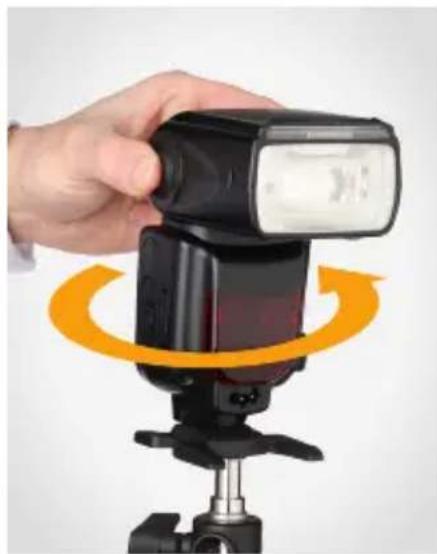
- Turn on your slave flash and set it to i-TTL and IR slave modes, as well as the same group and channel as the FreeWave IR Commander.
- After setting your slave flash, mount the flash and position it with its IR sensor facing the Commander by rotating the flash's base.
For information on how to perform these procedures with your particular flash, refer to your flash's manual.
Tip: You can combine multiple slave flashes within the same group to fire simultaneously.
natural_image
Hand holding a black motion capture camera with orange circular motion arrows (no text or symbols visible)When positioning wireless slaves to light a subject, keep in mind the following:
- Make sure the Commander's transmitter is facing your flash's IR sensor and that there are no obstructions between the two units (see Turning On the FreeWave IR Commander on page 12 for more).
- The effective communication range between the FreeWave IR Commander and your slave flash units may vary, depending on the ambient light.
- When photographing outdoors or in bright ambient light, the sensors can be overwhelmed by ambient light, which will lower their sensitivity.
natural_image
Black DSLR camera with adjustable lens and top mount (no visible text or symbols)MOUNTING THE FREEWAVE IR COMMANDER
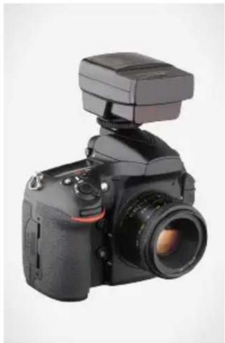
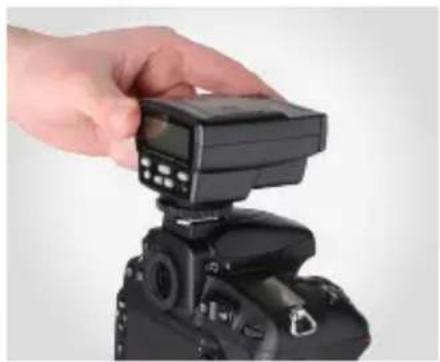
To mount the FreeWave IR Commander on your camera, make sure all devices are turned off and follow these steps:
- Looking down at the unit, rotate the locking wheel counterclockwise to loosen it.
- Slide the mounting foot all the way into your camera's hot shoe.
- Rotate the locking wheel clockwise until secure.
natural_image
Hand holding a black DSLR camera with an LCD screen, no visible text or symbols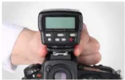
natural_image
Close-up of a hand holding a DSLR camera controller with a digital display (no visible text or symbols)To dismount the FreeWave IR Commander from your camera, make sure the Commander is turned off and follow these steps:
- Looking down at the unit, rotate the locking wheel counterclockwise to release it.
- Slide the mounting foot out of your camera's hot shoe.
TURNING ON THE FREEWAVE IR COMMANDER
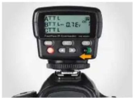
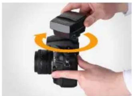
To turn on the FreeWave IR Commander, slide the power switch to the On position. When turning off the Commander, it will remember all your current settings.
Once mounted on your camera, you can rotate the Commander for line-of-sight positioning. The Commander's transmitter should be facing the flash's IR sensor, and there should be no obstructions between the two units.
natural_image
Close-up of hands holding a black DSLR camera with an orange circular motion indicator (no text or symbols)Test Button/Ready Light
The ready light indicates the status of the Commander. When it glows red, the Commander is ready to be fired. When the light is off, the Commander is recycling.
To fire a test flash, press the Test [§] button.
Tip: After changing any settings in your wireless setup, press the test button to fire a test flash and confirm your new settings. The slave flashes will fire at a nominal power setting for firing confirmation.
Automatic Power-saving Function
After a designated period of inactivity, the Commander will automatically enter power-saving mode to conserve battery life, and the LCD will display the standby mode indicator.
To reactivate the Commander, press the Set button or press your camera's shutter-release button halfway.
When reactivating via your camera's shutter button, standby time will be controlled by the camera's settings. When reactivating via the Commander's Set button, standby will occur after approximately 5 minutes of inactivity. During long periods of inactivity, use the power switch to turn off the Commander.
LCD Illumination
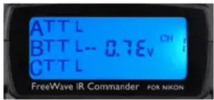
When you turn on the FreeWave IR Commander or press any button, the LCD will glow blue for up to six seconds.
5t bv
Standby Screen
Lock Mode
To prevent inadvertent operation of the Commander, you can deactivate its controls by setting it to lock mode. This will disable all of the buttons except for the power switch and the test button.
To lock the device, press and hold the FN button for five seconds until the lock icon [ 🔒] appears on the LCD.
To unlock the device, press and hold the FN button until the lock icon [ 🔊] disappears.
SELECTING CHANNELS
Lock IconChan
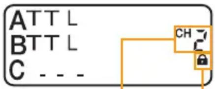
On the FreeWave IR Commander, four channels (1, 2, 3, and 4) are available. You can use this option to prevent your flashes from being triggered by another photographer panel working with a similar system nearby.
To select the channel, press the Set button repeatedly in any mode until the channel number blinks. Use the Left and Right [◀▶] navigation buttons to cycle through channels 1 through 4.
Note: Make sure your slave flashes are set to the same channel as the Commander.
ABOUT FLASH GROUPS
On the FreeWave IR Commander, three flash groups (A, B, and C) are available, with independent control over all three groups. For example, you can set one group to i-TTL mode and another to manual mode. You can also combine multiple slave flashes within the same group.
When setting groups on the Commander, make sure to set your slave flashes to the corresponding groups. To disable a group, choose the “- - -” setting on the Commander. Any flashes in this group will not fire.
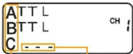
Flash Groups Disabled Flash Group
Note: Be aware of the independent recycling time of each flash to ensure all flash units are ready to fire.
i-TTL MODE
In i-TTL mode, the FreeWave IR Commander will automatically set the appropriate flash level via your camera's intelligent through-the-lens (i-TTL) metering system data, calculating the correct power for all communicating i-TTL compatible flashes.
On the FreeWave IR Commander, i-TTL mode and EV are set independently for each group.
Setting i-TTL mode: To set a group to i-TTL mode, follow these steps:
-
Press the Set button repeatedly until the desired group's mode indicator blinks.
-
Press the Mode button until the i-TTL mode indicator appears onscreen.
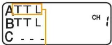
i-TTL Mode
Adjusting a Flash Group's
TTL Power (EV)
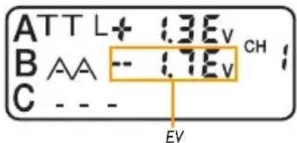
Flash output compensation (EV) can be set in i-TTL and AA modes (for more information about AA, refer to AA Mode on page 18). EV is displayed in decimal form and can be adjusted from -3.0 to +3.0 in 1/3-stop increments.
EV is set individually for each group.
To adjust EV:
-
Make sure the desired group is in i-TTL mode.
-
Press the Set button repeatedly until the EV number blinks, and use the Left and Right [◀▶] navigation buttons to adjust EV.
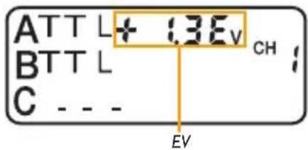
AUTO APERTURE MODE
In Auto Aperture (AA) mode, your flash's built-in sensor will automatically set the appropriate flash power output level by measuring the reflected light from the environment. This is different from i-TTL, which uses your camera's exposure sensor.
AA mode and EV are set independently for each group.
Setting AA Mode
To set a group to AA mode, follow these steps:
-
Press the Set button repeatedly until the desired group's mode indicator blinks.
-
Press the Mode button until the AA mode indicator appears onscreen.
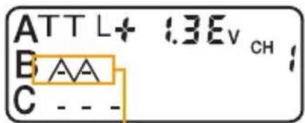
AA Mode
Adjusting a Flash Group's
TTL Power (EV)
Flash output compensation (EV) can be set in i-TTL and AA modes (for more information about i-TTL, refer to i-TTL Mode on page 16). EV is displayed in decimal form and can be adjusted from -3.0 to +3.0 in 1/3-stop increments.
EV is set individually for each group.
To adjust EV:
-
Make sure the desired group is in AA mode.
-
Press the Set button repeatedly until the desired EV number blinks, and use the Left and Right [◀▶] navigation buttons to adjust the EV.
MANUAL MODE
For greater creative control over your images, you can set the flash power output level manually.
Manual mode and flash power output are set independently for each group.
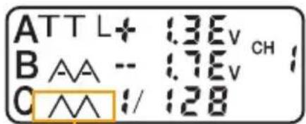
Setting Manual Mode
To set a group to manual mode, follow these steps:
-
Press the Set button repeatedly until the desired group's mode indicator blinks.
-
Press the Mode button until the desired mode indicator appears onscreen.
Manual Mode
Adjusting Power Output
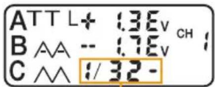
Flash power output is represented as a fraction. The 1/1 setting is the full-power flash, and each successive setting halves the light output, all the way down to 1/128. You can also fine-tune the flash output in increments of one-third, indicated by a hyphen next to the fraction, first higher and then lower, e.g., 1/1, 1/2-, 1/2-, 1/2, 1/4-, 1/4-, 1/4, 1/8-...
To adjust power output:
-
Make sure the desired group is in manual mode.
-
Press the Set button repeatedly until the desired power output blinks, and use the Left and Right [◀▶] navigation buttons to adjust the output.
Power Output
S1 OPTICAL SLAVE MODE
The S1 optical slave mode is ideal for shooting with a remote flash, such as a monolight, that has an optical sensor. In this mode, power output is adjusted on the slave flash, rather than the Commander. Unlike the TTL and Manual modes, S1 optical slave mode does not employ groups and channels.
To set S1 mode:
-
Press and hold the Mode button for five seconds until the S1 indicator appears onscreen.
-
Turn on your slave flash, and set it to optical slave mode. Make sure your slave flash's IR sensor is facing the Commander.
- Set the power output on your slave flash.
For information on how to perform these procedures with your particular flash, refer to your flash's user manual.
To exit S1 mode, press the Mode button.
FACTORY RESET
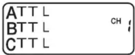
This restores the FreeWave IR Commander to the factory default settings. This will erase all current settings and replace them with the default settings.
To restore the factory settings, press and hold the Set button for five seconds until the Commander reverts to the default screen.
Default Screen
ADVANCED FEATURES
High-Speed Sync Mode
You can use shutter speeds that are faster than your camera's maximum flash sync speed with the FreeWave IR Commander by enabling high-speed sync (HSS) in your camera. HSS lets you use shutter speeds as fast as 1/8000 second. This is helpful when shooting with large apertures in brightly lit environments or when freezing motion.
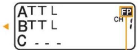
When HSS is enabled, the FP icon
[ ] will appear on the Commander's LCD. HSS is set in your camera menu. For more information on this feature, refer to your camera's user manual.
High Speed Sync Icon
Disabled Flash Group Repeating Mode
Repeating (Stroboscopic) Mode
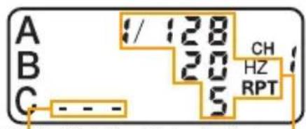
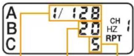
The repeating (stroboscopic) mode fires the flash multiple times in quick succession during a single exposure. In stroboscopic mode, you can adjust flash output, stroboscopic frequency, and flash count. Stroboscopic frequency is measured in hertz (Hz) and indicates the number of flashes per second. The flash count (RPT) represents the number of flashes per frame.
To set the FreeWave IR Commander to stroboscopic mode, follow these steps:
- Mount the Commander on your camera.
- Press the Mode button to enter stroboscopic mode.
-
Press the Set button repeatedly until the desired group indicator blinks, and press the Mode to enable or disable the group.
-
Press the Set button repeatedly until the flash output level blinks, and use the Left and Right [◀▶] navigation buttons to adjust the output from 1/128 to 1/4.
- Press the Set button to make the stroboscopic frequency number blink, and use the Left and Right [◀▶] navigation buttons to adjust the frequency from 1 to 100.
- Press the Set button to make the flash count number blink, and use the Left and Right [◀▶] navigation buttons to adjust the count from 1 to 24.
Flash Output Frequency Flash Count
The Modeling Light
The modeling light gives the appearance of a continuous light so you can approximate how the flash will illuminate your subject, and is available on cameras that have a Depth of Field Preview button. To activate the modeling light feature, press your camera's Depth of Field Preview button. The flash will pulse rapidly to simulate the direction of light. Note: Using the modeling light will greatly decrease your batteries' output.
AF Illumination Icon
Autofocus Assist
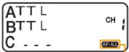
Camera autofocus (AF) systems can have difficulty locking onto a subject in dim light or low-contrast scenes. The FreeWave IR Commander can emit a red autofocus-assist beam to help your camera focus automatically by locking onto the projected light.
To enable AF assist on the Commander, press the FN button. The AF-ILL icon [AF-ILL] appear on the Commander's LCD when this feature is enabled. When your camera's internal AF-ILL is on, it will enable the camera's AF assist but not the Commander's. For further details, see the table below.
| Setting Result | |
| Commander's AF-ILL is on | er's AF assist is on |
| Commander's AF-ILL is off and camera's internal AF-ILL is on | Commander's AF assist is off and camera's AF assist is on |
| Commander's AF-ILL is off and camera's internal AF-ILL is off | Commander's AF assist is off and camera's AF assist is off |
Flash Exposure Bracketing
Flash exposure bracketing (FEB) lets you take three continuous pictures while automatically changing the flash exposure compensation between -3 and +3, once above and once below the set flash exposure. FEB is useful for shooting in situations in which it's difficult to determine the appropriate flash exposure.
The FEB function can be activated via your camera's menu. For more information on this feature, refer to your camera's user manual.
Flash Value Lock
In i-TTL mode, you can lock the flash output level that is optimal for specific elements of your scene by using the flash value lock (FV Lock) feature. FV lock overrides any flash exposure settings.
The FV Lock function can be activated via your camera's menu. For more information on this feature, refer to your camera's user manual.
SPECIFICATIONS
| Transmission | |
| Transmission Range | |
| Channels | |
| Groups | |
| Flash Coverage | Horizontal: 40°Vertical: 30° |
| Display | |
| Controllable Remote Flash Mode | TL, AA, Manual, Stroboscopic |
| Power Source | |
| Dimensions | × 8.3 cm) |
| Weight |
TROUBLESHOOTING
The Commander is stuck in the camera hot shoe.
• Make sure that the mounting foot lock is released.
The Commander is not flashing.
• Make sure that fresh batteries are installed and in the proper orientation.
• Make sure the Commander is securely attached to the camera.
• Make sure that the electrical contacts on the foot of the Commander are not dirty. Clean them and try again.
- Make sure the Commander is fully installed in your camera's hot shoe.
The slave units are not firing.
- Make sure the hot-shoe light's locking switch is set to the lock position.
- Make sure the slave units are turned on and at the correct settings.
- Remove the batteries from the slave units and the Commander, wait a moment, and then replace.
-
Make sure that the slave units are set to IR slave and i-TTL modes, even when using the Commander to trigger in manual mode, and that their channel and group match up with those of the Commander.
-
Make sure that the Commander is within the transmission range and the wireless sensor on the slave is pointing toward the Commander. Remove any obstructions in the line of sight between the two.
- Ambient light may affect IR transmission
• Make sure that the electrical contacts on the foot of the slave unit are not dirty. Clean them and try again.
- Change the channel on both the Commander and the slave flash units. Make sure all units are set to the same channel.
Note: After changing any settings in your wireless setup, press the test button to fire a test flash and confirm your new settings.
ONE-YEAR LIMITED WARRANTY
This VELLO product is warranted to the original purchaser to be free from defects in materials and workmanship under normal consumer use for a period of one (1) year from the original purchase date or thirty (30) days after replacement, whichever occurs later. The warranty provider's responsibility with respect to this limited warranty shall be limited solely to repair or replacement, at the provider's discretion, of any product that fails during normal use of this product in its intended manner and in its intended environment. Inoperability of the product or part(s) shall be determined by the warranty provider. If the product has been discontinued, the warranty provider reserves the right to replace it with a model of equivalent quality and function.
This warranty does not cover damage or defect caused by misuse, neglect, accident, alteration, abuse, improper installation or maintenance. EXCEPT AS PROVIDED HEREIN, THE WARRANTY PROVIDER MAKES NEITHER ANY EXPRESS WARRANTIES NOR ANY IMPLIED WARRANTIES, INCLUDING BUT NOT LIMITED TO ANY IMPLIED WARRANTY OF MERCHANTABILITY OR FITNESS FOR A PARTICULAR PURPOSE. This warranty provides you with specific legal rights, and you may also have additional rights that vary from state to state.
To obtain warranty coverage, contact the Vello Customer Service Department to obtain a return merchandise authorization (“RMA”) number, and return the defective product to Vello along with the RMA number and proof of purchase. Shipment of the defective product is at the purchaser's own risk and expense.
For more information or to arrange service, visit www.vellogear.com or call Customer Service at 212-594-2353.
Product warranty provided by the Gradus Group.

VELLO™ A Gradus Group Brand
www.gradusgroup.com
VELLO is a registered trademark of the Gradus Group.
© 2016 Gradus Group LLC. All Rights Reserved.
www.vellogear.com
VELLO is a registered trademark of the Gradus Group.
© 2016 Gradus Group LLC. All Rights Reserved.
All other trademarks are the property of their respective owners.
GG2
- THANK YOU FOR CHOOSING VELLO
- TABLE OF CONTENTS
- PRECAUTIONS
- KEY FEATURES
- OVERVIEW
- Also Included
- COMPATIBLE DEVICES INSTALLING BATTERIES
- SETTING UP SLAVE FLASH UNITS
- MOUNTING THE FREEWAVE IR COMMANDER
- TURNING ON THE FREEWAVE IR COMMANDER
- Test Button/Ready Light
- Automatic Power-saving Function
- LCD Illumination
- Lock Mode
- SELECTING CHANNELS
- ABOUT FLASH GROUPS
- i-TTL MODE
- Adjusting a Flash Group's
- TTL Power (EV)
- AUTO APERTURE MODE
- Setting AA Mode
- MANUAL MODE
- Setting Manual Mode
- Adjusting Power Output
- S1 OPTICAL SLAVE MODE
- FACTORY RESET
- ADVANCED FEATURES
- High-Speed Sync Mode
- Repeating (Stroboscopic) Mode
- The Modeling Light
- Autofocus Assist
- Flash Exposure Bracketing
- Flash Value Lock
- TROUBLESHOOTING
- The Commander is not flashing.
- The slave units are not firing.
- ONE-YEAR LIMITED WARRANTY
Brand : Vello
Model : FreeWave IR Commander
Category : Remote control