
Source 4WRD - Uncategorized ETC - Free user manual and instructions
Find the device manual for free Source 4WRD ETC in PDF.


| Product Type | LED Retrofit Kit for Source Four Fixtures |
| Model | Source 4WRD |
| Manufacturer | ETC (Electronic Theatre Controls) |
| Weight (Retrofit Kit Only) | 3.65 lb (1.66 kg) |
| Weight (Installed on 26° Fixture with Yoke and C-Clamp) | 14 lb (6.35 kg) |
| Power Input | 114–125 VAC, 60 Hz |
| Power Consumption (Full Intensity) | 155.7 W / 1.35 A |
| Idle Power / Current (DMX Mode) | 1.2 W / 0.046 A |
| LED Type | 4 CREE LED Modules |
| LED Lifetime (L70) | 30,000 hours (estimated) |
| Color Rendering Index (CRI) Options | 80 CRI or 90 CRI (Gallery) |
| Control Protocols | DMX512-A, AC line-dimmed, Local |
| DMX Addressing | 1–512 via two-button interface |
| Ambient Operating Temperature | 5°C to 50°C (41°F to 122°F) |
| Minimum Storage Temperature | 5°C (41°F) |
| Maximum External Surface Temperature | 63°C (145°F) at Ta=50°C |
| Construction | Rugged die-cast aluminum |
| Compatible Accessories | All ETC Source Four lens tubes, pattern holders, color frames, drop-in iris |
| Cleaning Instructions | Use oil-free canned air for LED domes; isopropyl alcohol/water for lenses |
| Safety Cable Attachment | Yes, via hole in housing tab |
Frequently Asked Questions - Source 4WRD ETC
User questions about Source 4WRD ETC
0 question about this device. Answer the ones you know or ask your own.
Ask a new question about this device
Download the instructions for your Uncategorized in PDF format for free! Find your manual Source 4WRD - ETC and take your electronic device back in hand. On this page are published all the documents necessary for the use of your device. Source 4WRD by ETC.
USER MANUAL Source 4WRD ETC
Installation and User Manual
Version 1.1.0
Part Number: 7067M1200-1.1.0 Rev: C
Released: 2017-07
ETC ^® , Source Four ^® , Source 4WRD ^™ , Sensor ^® , and Unison ^® are either registered trademarks or trademarks of Electronic Theatre Controls, Inc. in the United States and other countries.
All other trademarks, both marked and not marked, are the property of their respective owners.
This product is protected by one or more of the following U.S. Patents: US 9,261,241 and 9,273,831.
ETC intends this document, whether printed or electronic, to be provided in its entirety. This product is intended for professional use only. Read this entire document before using this product.
Table of Contents
Introduction 1
Safety 2
Specifications 4
Sensor dimmer settings 5
Color rendering and quality 6
Contacting ETC 7
Retrofit kit installation 8
Remove incandescent lamp housing ..... 8
Install Source 4WRD retrofit....9
Fixture installation 10
Attach C-clamp and safety cable ..... 10
Connect cables.... 11
DMX pinout 12
User interface 12
Error codes 13
Focus the fixture 13
Set the Z-adjustment ..... 13
Adjust the yoke position 14
Change the height position.... 14
Set the angle within the yoke ..... 14
Shape the beam.... 14
Use the color frame 14
Use a pattern 15
Cleaning and maintenance..... 15
Clean the fixture....15
Store the retrofit 16
Clean the lenses 16
Clean the reflector ..... 17
Clean 5° and 10° polymer lenses ..... 18
Introduction
Congratulations on your purchase of the ETC Source 4WRD LED retrofit kit. Replacing your existing incandescent burner assembly with the Source 4WRD LED brings a new tool to your lighting inventory. The Source 4WRD LED expands the options for existing Source Four® fixtures and adds a new white LED fixture to the ETC family.
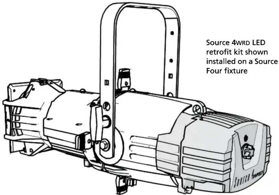
The following Source 4WRD options are available as 80 CRI and 90 CRI (Gallery) variants:
- Source 4WRD LED retrofit kit: Used to modify an existing Source Four HPL incandescent fixture to a white LED fixture. The Source 4WRD LED can also be used with the Source 4WRD PAR or PARNel® Fixture Body to create a Source 4WRD PAR or PARNel fixture. For more information, visit etcconnect.com.
- Source 4 WRD Light Engine: Combines the Source Four incandescent fixture body with the Source 4WRD LED.

Note: Source 4WRD LED retrofit kit is not compatible with Source Four LED, Fresnel, PAR, or jr fixtures.

WARNING: The Source 4WRD LED is not user serviceable. Field modification of the Source 4WRD LED will void your ETC warranty.
Safety
The Source 4WRD fixture is intended for professional use only. Read the entire manual before using this equipment.

WARNING: Note the following safety warnings before use:
- Do not mount the Source 4 WRD fixture on or near a flammable surface.
- Do not use the Source 4 WRD fixture below 5^ (41°F).
- Minimum storage temperature is 5°C (41°F). When the fixture has been stored or transported in cold temperatures, allow it to warm to room temperature for a minimum of 1 hour before applying power. Applying power to a cold fixture will cause damage to the fixture and void the ETC warranty.
- Do not use this fixture with a damaged power lead. If the power lead (cord set) is damaged, it must be replaced.
- Do not use this fixture if glass lens is deeply scratched or cracked. Damaged lenses must be replaced.
- To prevent wiring damage, or abrasion, do not expose wiring to edges of sheet metal or other sharp objects.
- Use the Source 4 WRD fixture in dry locations only, where humidity does not exceed 90 percent (non-condensing). These fixtures are not intended for outdoor use.
- Mount and support the fixture only by the primary suspension holes in the yoke.
- Suspend the fixture from a suitable structure using only hardware rated for the weight of the fixture.
- In addition to primary suspension, attach a safety cable (ETC Model 400SC or other approved safety cable or device) to the fixture housing. An appropriate attachment point (hole) is provided in the protruding tab on the fixture housing.
- Disconnect the unit from power and DMX and allow the fixture to cool before removing or installing the shutter barrel or other adapters, and for performing all cleaning and maintenance.
Note: • Maximum recommended ambient operating temperature: Ta=50°C (122°F)
• Maximum anticipated external surface temperature: T_max=63^ (145°F) at T_a=50^ (122°F)
- External Temperature (steady state achieved) at 25^ (77°F) ambient: 38^ (100°F)
Specifications
| Typical Power Consumption | |
| Idle Power / Current DMX Mode: 1.2W/.046A; AC Mode: 0W | |
| Full Intensity Power / Current 155.7W/1.35A | |
| Physical | Rugged die-cast aluminum constructionAdvanced thermal management systems for long LED lifeAmbient operating temperature: 5°–50°C (41°F–122°F)Minimum storage temperature: 5°C (41°F)Weight:- Source 4WRD LED retrofit kit only: 3.65 lb (1.66 kg)- Source 4WRD LED installed on 26° fixture with yoke and C-clamp:14 lb (6.35 kg) |
| Electrical | 114–125VAC 60Hz power input155W draw at full (182W theoretical max. draw)Recommended two (2) fixtures per dimmed circuit (D20 module)Max of 14 fixtures per non-dimmed circuit (R20 module)If using in DMX mode: Connect fixture to relay, constant power, or dimmer with regulation off and parked at full |
| LEDs | 4 CREE LED modules30,000 hour estimated L70 rating (life-test in progress, results pending) |
| Optical • Compatible with all ETC Source Four lens tubes | |
| Control | DMX512-A compliantDMX in and thru via two RJ45 connectorsAC power for line-dimmed operationSimple seven-segment display and two-button user interface includes local dimming control |

Note: Connecting both power and data from a SmartBar 1 to a Source 4WRD fixture may cause flickering.
Sensor dimmer settings
The Source 4WRD fixture can be dimmed from a DMX source, an existing dimmer, or locally on the fixture.
When powering a fixture with a CEM classic, CEM+, or CEM3 for DMX dimming or AC level setting, set the parameters as shown below to ensure that the dimmer is out of regulated mode.
The following tables apply to ETC Sensor® control modules including CEM, CEM+, and CEM3.

Note: You may need to adjust dimmer settings for optimal fixture control.

Note: In CEM+, set Max Scale to 140V to guarantee that regulation is off.
CEM+ and CEM3
| Parameter Value | |
| Curve Mod Square | |
| Threshold 1% | |
| Min Scale 6V | |
| Max Scale 140V | |
| Regulation OFF | |
| Preheat Disabled | |
| DC Prevent OFF | |
| Inrush Protect OFF | |
| Scale Load 100 |
CEM Classic v2.x CEM Classic v3.x
| Parameter Value | Parameter Value |
| Mode Normal Mode | Normal |
| Boost | 117 |
| Curve Mod-Square | |
| Scale | 140 |
| Threshold Normal |
Note: With AC dimming (line-dimmed) mode, performance may vary based on the control settings of the dimmer used. For this reason, ETC recommends using AC dimming for level-setting or for architectural quality dimming situations. ETC recommends testing the Source 4WRD fixture on all existing dimmers you wish to use. Use DMX mode when high-performance, live, dynamic dimming is required.
You may need to increase the SCR Off Time from the default setting. Contact ETC for assistance in changing the SCR Off Time, or any other CEM classic, CEM+, or CEM3 settings.
For the most current information on additional dimmer performance testing for both ETC and non-ETC dimmers, please visit the ETC website: etcconnect.com/Support/Articles/Dimmer-Settings-for-Use-with-Source-4wrd.aspx
Color rendering and quality
Source 4WRD fixtures are evaluated for Color Rendering Index (CRI) and Color Quality Scale (CQS) performance using measured output spectrum. These numbers may fluctuate slightly from fixture to fixture. This is a normal characteristic of white LEDs, and this kind of variation is highly unlikely to be apparent in most applications.
| Fixture CRI CQS Color Fidelity Duv | ||||
| Source 4WRD LED(80 CRI) at 3000K | ≥80 80 80 0.001 | |||
| Source 4WRD LED Gallery(90 CRI) at 3000K | ≥90 90 90 0.001 | |||
Contacting ETC
If you are having difficulties, your most convenient resources are the references given in this user manual. To search more widely, try the ETC website at etcconnect.com. If none of these resources is sufficient, contact ETC Technical Services directly at one of the offices identified below. Emergency service is available from all ETC offices outside of normal business hours.
When calling for help, please have the following information handy:
- Product model
- Dimmer manufacturer and installation type
- Other components in your system (Unison ^® , other consoles, etc.)
Americas United Kingdom
ETC, Inc. ETC Ltd
Technical Services Department Technical Services Department
3031 Pleasant View Road 26-28 Victoria Industrial Estate
Middleton, WI 53562 Victoria Road,
800-775-4382 (USA, toll-free) London W3 6UU England
+1-608 831-4116 +44 (0)20 8896 1000
service@etcconnect.com service@etceurope.com
Asia Germany
ETC Asia ETC GmbH
Technical Services Department Technical Services Department
Room 1801, 18/F Ohmstrasse 3
Tower 1, Phase 1 Enterprise Square 83607 Holzkirchen, Germany
9 Sheung Yuet Road +49 (80 24) 47 00-0
Kowloon Bay, Kowloon, Hong Kong techserv-hoki@etcconnect.com
+852 2799 1220
service@etcasia.com
Retrofit kit installation

WARNING: RISK OF FIRE OR ELECTRIC SHOCK: Source 4WRD LED retrofit kit installation requires knowledge of luminaire electrical systems. If not qualified, do not attempt installation. Contact a qualified electrician.

Note: THE RETROFIT KIT IS ACCEPTABLE AS A COMPONENT OF A LUMINAIRE WHERE THE SUITABILITY OF THE COMBINATION SHALL BE DETERMINED BY AUTHORITIES HAVING JURISDICTION.
A #2 Phillips screwdriver is needed for kit installation
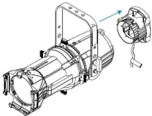
Remove incandescent lamp housing
1: Unplug the Source Four incandescent fixture and place it on a flat, stable surface.
2: Loosen the brass thumb screw located above the beam adjustment knob. The lamp housing is now loose and can be removed.
natural_image
Technical line drawing of an electric motor assembly with a close-up view of its internal components (no text or symbols present)
Note: The burner assembly is no longer needed. If you would like ETC to recycle the burner assembly, contact ETC Technical Services for more information. See Contacting ETC on page 7.
Install Source 4WRD retrofit

WARNING: RISK OF FIRE OR ELECTRIC SHOCK: Install this kit only onto luminaires that have the construction features and dimensions shown in the images in this document and where the input rating of the retrofit kit does not exceed the input rating of the luminaire.

WARNING: Do not make or alter any open holes in an enclosure of wiring or electrical components during kit installation.

CAUTION: Do not touch or clean LED optic domes with anything other than oil-free canned air.
1: Use oil-free canned air to clean the LED domes prior to installation.
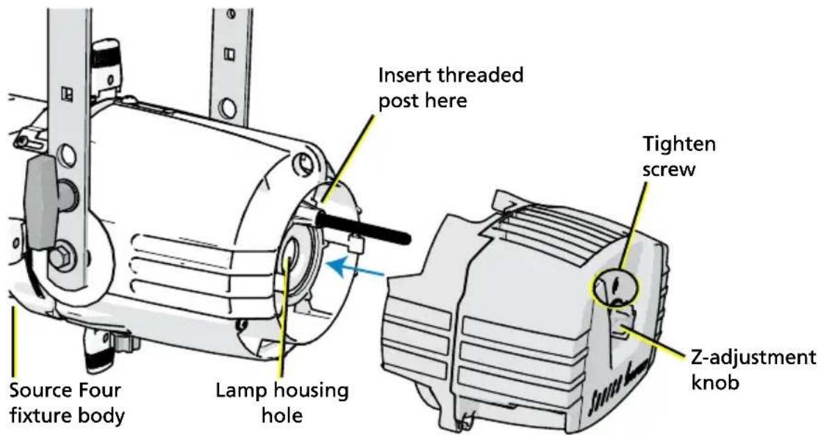
2: With the fixture resting securely on a flat surface, attach the supplied threaded post to the back end of the fixture body. Use a crescent wrench to tighten the threaded post one-quarter turn past finger tight.
3: Gently slide the Source 4 WRD LED onto the fixture body and threaded post while guiding the LED tower into the lamp housing hole, as shown below. Take care to prevent contact between the LEDs and the reflector.
4: Use a #2 Phillips screwdriver to tighten the screw located on the back end of the Source 4WRD LED, directly above the Z-adjustment knob.
5: Pull gently to verify secure attachment.
Fixture installation
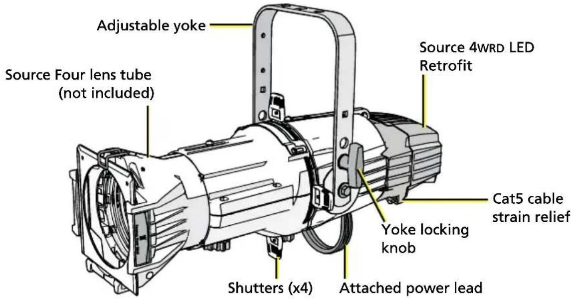
The Source 4WRD Light Engine combines the classic form factor of the Source Four incandescent fixture with an LED light source. The Source 4WRD Light Engine includes an adjustable yoke, C-clamp, and attached power lead.
Attach C-clamp and safety cable
The C-clamp attaches the fixture to the mounting pipe and allows you to adjust the position of the mounted fixture. ETC recommends using 1.5" schedule 40 pipe.
1: Tightly fasten the C-clamp to the yoke with the provided yoke bolt and lock washer.
2: Place the C-clamp on mounting pipe, then tighten the pipe bolt to secure it.
3: Loosen the C-clamp pan screw and rotate the yoke to the desired position.
4: Tighten the pan screw to lock the fixture.
5: Connect the safety cable.
6: Tighten C-clamp pipe bolt to 15–20 ft lbs (20–27 Nm), approximately finger tight plus up to one-quarter turn.

CAUTION: Do not exceed 25 ft lbs (33 Nm) while tightening the C-clamp pipe bolt. Do not use excessive force.
7: Tighten the yoke pivot bolt to 5–10 ft lbs (6–7 Nm), approximately finger tight plus up to one-eighth turn.

CAUTION: Do not exceed 15 ft lbs (20 Nm) while tightening the yoke pivot bolt. Do not use excessive force.
Connect cables
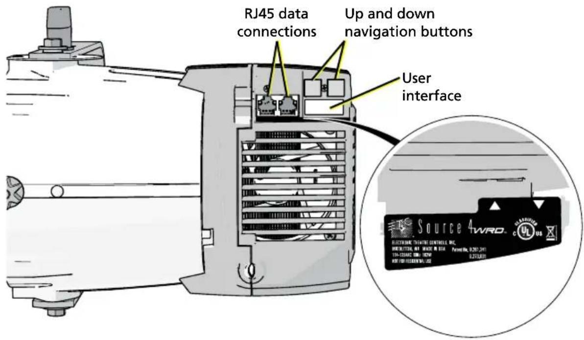
The fixture can be controlled by AC power or DMX. The fixture responds to the control method selected using the user interface. For more information, see User interface on page 12.

Note: Make sure your dimmer is out of regulated mode for optimum performance. See Sensor dimmer settings on page 5 for recommended dimmer settings.

Note: Connecting both power and data from a SmartBar 1 to a Source 4WRD fixture may cause flickering.

WARNING: Do not use or store the Source 4WRD fixture below 5°C (41°F). When the fixture has been stored or transported in cold temperatures, allow it to warm to room temperature for a minimum of 1 hour before applying power. Applying power to a cold fixture will cause damage to the fixture and void ETC warranty.
1: If using DMX control: Connect one RJ45 data cable for data-in and one for data-thru, as needed.
- To order RJ45 to female XLR adapter, use ETC part number W6538.
- To order RJ45 to male XLR adapter, use ETC part number W6539.
2: When connecting data, consider the following:
- Two strain reliefs are built in to the bottom of the Source 4WRD fixture and should be used to support the fixture's data cable.
- When using DMX over Cat5, use Cat5e or better. Cable distance must not exceed 300 m (1000 ft).
- The Source 4 WRD fixture cannot be controlled via network protocols and should not be connected to a system network.
- Up to 32 fixtures can be connected together into a daisy chain.

Note: The fixture is not self terminating. You must terminate the last fixture in line with a 120 Ohm resistor. Please contact your ETC customer service representative to purchase ETC part number N4086.
3: Connect fixture to power source.
DMX pinout
| Pin Description Pin Description | ||
| 1 DMX + 5 Not Connected | ||
| 2 DMX - 6 Not Connected | ||
| 3 Not Connected 7 Iso Common (Shield) | ||
| 4 Not Connected 8 Not Connected |
User interface
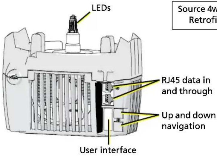
The two-button, seven-segment display shows the DMX address, AC mode, or the manually-set level.
- Set a DMX address: Use the up and down arrows to navigate to the desired DMX address number (1–512).
- Set the fixture to AC mode: Use the down arrow to navigate one number below DMX address 1. The display will read RC.
- Manually set a level: Use the down arrow to navigate one number below RC. The display will read L_FL (Level = Full). Use the down arrow to decrease the level to a percentage of full (L_99 = 99%, L_98 = 98%, etc.). You can set levels from 0%–100% (full).
Error codes
The following error codes may be seen on the Source 4WRD user interface.
- OEP indicates the fixture has gone into over-temperature protection. Reset the fixture to clear the code.
- For DMX mode: Return the DMX control to 0.
- For AC mode: Remove the fixture from power for five seconds and then restore power.
- UEP indicates the fixture has gone into under-temperature protection. Allow the fixture to warm to a minimum of 5°C (41°F).
- Flashing DMX address indicates loss of DMX.
- Dark screen indicates loss of power or fixture time-out. In the event of time-out, press any button to wake the user interface.
Focus the fixture
Set the Z-adjustment
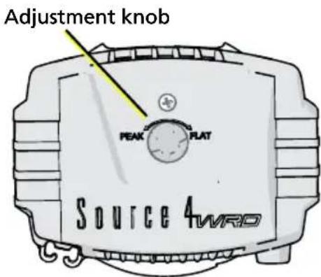
Use the Z-adjustment knob located on the rear of the Source 4WRD fixture to adjust the field of the LED light for specific applications.
This shows an ideal beam of uniform light
Adjust towards PEAK to blend overlapped beams
Adjust towards FLAT to improve sharp focus

natural_image
Three circular shapes with varying grayscale shading, arranged vertically against a black background (no text or symbols)1: Turn on the Source 4WRD fixture and aim it at a flat surface.
2: Slide the fixture barrel towards or away from the Source 4 WRD LED to create a hard-edged beam of light.
3: Turn the knob toward PEAK or FLAT until the desired field is obtained.
Adjust the yoke position
Change the height position
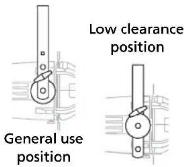
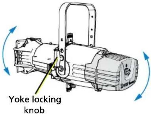
1: Remove the yoke locking knobs, washers, and hex bolts from either side of the fixture.
2: Raise or lower the fixture to the desired position within the yoke.
3: Reinstall the yoke's hex bolts, washers, and locking knobs.
4: Tighten the yoke knobs to secure in position.
Set the angle within the yoke
1: Loosen the yoke locking knob. Do not remove the knob.
2: Tilt the fixture to the desired position.
3: Tighten the yoke locking knob to secure in position.
Shape the beam
You can shape the beam by using the shutters, a pattern, an optional drop-in iris, and by rotating the barrel.
Use the color frame
The color frame holder is equipped with a spring-loaded retaining clip that prevents color frames and accessories from falling out.
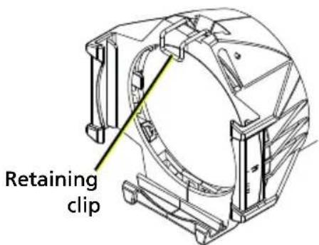

WARNING: Make sure all color frame accessories are locked in position with the retaining clip before hanging the Source 4WRD fixture.
1: Release the retaining clip by pushing it sideways while gently pulling backwards.
2: Insert the color frame.
3: Lock the retaining clip by pushing sideways while gently pushing forward.
Use a pattern
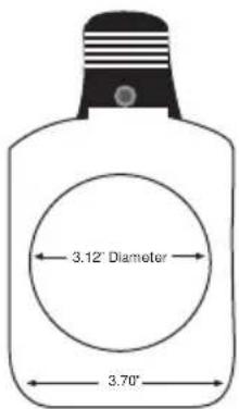
The pattern holder slot is on the top side of the barrel and in front of the shutters. It accommodates A-size, B-size, and glass pattern holders.
A-size pattern holder: Holds 3" diameter patterns
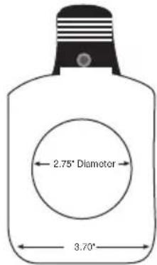
B-size pattern holder: Holds 2.5" and 2.75" diameter patterns

Note: Because the Source 4WRD aperture is 3 inches wide, ETC recommends using A-size patterns for maximum pattern effectiveness.
Cleaning and maintenance
Clean the fixture
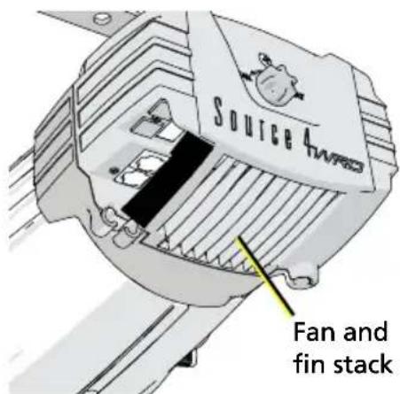
- Use oil-free canned air to clean the LED domes prior to installation and prior to storage.
- Use oil-free canned air to clean the fan and fin stack as part of regular fixture maintenance.
- When not installed on the fixture, store the Source 4WRD LED in its original packaging or in a dust-resistant plastic bag.

CAUTION: Do not touch or clean LED optic domes with anything other than oil-free canned air.
Store the retrofit
- Store the Source 4WRD LED at temperatures of 5^ (41°F) or higher.
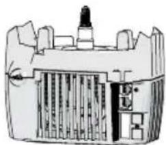
- If you must store the Source 4 WRD LED below 5^ (41°F), make sure it is in an upright position as shown to the right. Allow it to warm to room temperature for a minimum of one hour before applying power.
Store with LED dome up
natural_image
Cross-sectional diagram of a mechanical or electrical component with no visible text or symbols
Note: After shipping or storing the Source 4WRD LED below 5°C (41°F), visually inspect the unit to ensure the low temperatures have not caused cracking of the LED array.
Clean the lenses

WARNING: Do not use ammonia-based or other harsh commercial cleaners. Clean lens and reflector only as directed. Commercially available glass cleaning agents should be avoided as they may contain ammonia, other harsh chemical detergents or abrasive agents. These cleaners may damage the glass surface and the Anti-Reflective coatings. Do not immerse or soak the glass in any cleaning solution.
Replace lenses if they contain visible damage (cracks or deep scratches) that may impair their effectiveness.

Note: To clean the inside of lenses, you must remove the lenses from the lens tube. For instructions on removing the lenses, see the Source Four Assembly Guide, which is available for download at etcconnect.com.
1: Remove the lens tube from the fixture barrel:
a: Remove the beam focus knob and retainer bolt from the top of the barrel and set aside.
b: Slide the lens tube out of the barrel.
2: Remove any dust from inside the lens tube with a blast of oil-free air or wipe with a clean, lint-free cloth. Isopropyl alcohol, distilled water, or a 50%-50% mixture of each can be used to clean the glass surface.
3: Slide the lens tube back into the barrel with the color frame retaining clip on top. Reinstall the beam focus knob and retainer bolt.

WARNING: Unplug the fixture before attempting to clean the reflector.
To quickly clean the reflector, remove the lens tube and clean the dust from the reflector with a blast of oil-free air. You may also wipe the reflector with a clean lint-free cloth. If either method is not sufficient, follow these steps.
1: To protect the lamp housing during cleaning, remove the LED lamp housing by loosening the attachment screw and pulling the housing straight out. (See image on page 9.)
2: Remove the barrel rotation knob located at the bottom of the barrel. Use a Phillips screwdriver to remove the retainer bolt located on top of the reflector housing.
3: Rotate the barrel 45^ in either direction. Carefully remove the barrel from the reflector housing.
4: Remove dust with a blast of oil-free air or wipe with a clean, lint-free cloth. Isopropyl alcohol, distilled water, or a 50%-50% mixture of each can be used to clean the glass surface.
5: Insert the barrel into the reflector housing with the iris/pattern slot on top. Align the triangles on both parts.
6: While gently pressing in, rotate the barrel 45^ clockwise until it sets into position, then rotate the barrel counterclockwise 45^ . The barrel should be firmly attached and the triangles should be aligned.
7: Reinstall the barrel rotation knob and tighten the retainer bolt.
8: Reinstall the LED lamp housing and tighten the attachment screw. See Install Source 4WRD retrofit on page 9.
Clean 5° and 10° polymer lenses
To quickly clean the lenses, remove dust with a blast of oil-free air. If this is not sufficient, follow these steps.

CAUTION: Handle polymer lenses by their edges only. Never rub anything dry on a polymer lens.
1: Remove the beam focus knob at the bottom of the barrel. Remove the lens tube from the barrel.
2: Use a Phillips screwdriver to remove the brackets that hold the lens in place. Remove the lens from the tube.
3: Dip the lens in a clean isopropyl alcohol/water mixture (9 parts water to 1 part isopropyl alcohol).
4: Use a soft moistened nylon bristle brush to wash the smooth side of the lens in a linear (non-circular) motion.
5: Use the same brush to lightly wash the ridged side of the lens by following its ridges.
6: Dip the lens in a clean isopropyl alcohol/water mixture (9 parts water to 1 part isopropyl alcohol).
7: Dry the smooth and ridged surfaces with an air gun. Make sure the air flow moves liquid away from you.
8: Inspect the lens for dirt. Repeat steps 3–7 if necessary.
9: Set the lens back in the lens tube with the ridged side facing the front of the tube. Reinstall the lens brackets.
10: Slide the lens tube back into the barrel with gel frame retainer on top. Reinstall beam focus knob.
ETC.
Corporate Headquarters ■ Middleton, Wisconsin, USA ■ Tel +608 831 4116
Service (Americas) ■ service@etcconnect.com
London, UK ■ Tel +44 (0)20 8896 1000 ■ Service: (UK) service@etceurope.com
Rome, IT ■ Tel +39 (06) 32 111 683 ■ Service: (UK) service@etceurope.com
Holzkirchen, DE ■ Tel +49 (80 24) 47 00-0■ Service: (DE) techserv-hoki@etcconnect.com
Hong Kong ■ Tel +852 2799 1220■ Service: (Asia) service@etcasia.com
Web:etcconnect.com ■Copyright © 2017 Electronic Theatre Controls, Inc. All Rights
Reserved. ■ Product information and specifications subject to change. ■ ETC intends this
document to be provided in its entirety
7067M1200-1.1.0 ■Rev C ■Released 2017-07
- Installation and User Manual
- Table of Contents
- Introduction 1
- Contacting ETC 7
- Retrofit kit installation 8
- Fixture installation 10
- User interface 12
- Focus the fixture 13
- Cleaning and maintenance..... 15
- Introduction
- Safety
- WARNING: Note the following safety warnings before use:
- Specifications
- Sensor dimmer settings
- Color rendering and quality
- Contacting ETC
- Americas United Kingdom
- Asia Germany
- Retrofit kit installation
- Remove incandescent lamp housing
- Install Source 4WRD retrofit
- Fixture installation
- Attach C-clamp and safety cable
- Connect cables
- DMX pinout
- User interface
- Error codes
- Focus the fixture
- Set the Z-adjustment
- Adjust the yoke position
- Change the height position
- Set the angle within the yoke
- Shape the beam
- Use the color frame
- WARNING: Make sure all color frame accessories are locked in position with the retaining clip before hanging the Source 4WRD fixture.
- Use a pattern
- Cleaning and maintenance
- Clean the fixture
- Store the retrofit
- Clean the lenses
- WARNING: Unplug the fixture before attempting to clean the reflector.
- Clean 5° and 10° polymer lenses
- CAUTION: Handle polymer lenses by their edges only. Never rub anything dry on a polymer lens.
Brand : ETC
Model : Source 4WRD
Category : Uncategorized