
Venue 2 - Receiver Lectrosonics - Free user manual and instructions
Find the device manual for free Venue 2 Lectrosonics in PDF.


| Product Type | Modular Wireless Microphone Receiver |
| Brand | Lectrosonics |
| Model | Venue 2 (VRM2) |
| Frequency Bands (VRM2WBL) | A1, B1, B2, C1 (470.100 - 691.175 MHz) |
| Frequency Bands (VRM2WBM) | B1, B2, C1, C2 (537.600 - 716.700 MHz) |
| Number of Receiver Modules | Up to 6 |
| Receiver Type | Triple Conversion Superheterodyne |
| Diversity Methods | Antenna Phase Switching (Smart Diversity) and Opti-Blend Ratio Diversity |
| Audio Outputs | 6 x Balanced XLR (line level) |
| Frequency Response | 32 Hz - 20 kHz (±1 dB, overall system in 400 Series mode) |
| Signal-to-Noise Ratio (SmartNR OFF, with limiting) | 108.5 dB |
| Total Harmonic Distortion | 0.2% (typical) |
| Digital Latency | 1.5 ms (receiver only, hybrid mode) |
| Power Requirements | 10-18 VDC, 1.2-2 A (center pin positive) |
| Dimensions (W x H x D) | 19 x 1.75 x 7.75 inches (48.26 x 4.45 x 19.67 cm) |
| Weight (with six modules) | 4.4 lbs (1984 g) |
| Antenna Inputs | 2 x BNC (with DC bias for remote amplifiers) |
| Multicoupler Outputs | 2 x BNC (loop thru to additional Venue 2 units) |
| Computer Interfaces | USB (1.1), Ethernet, RS-232 |
| Front Panel Display | High resolution graphical LCD with backlight |
| Smart Tune | Automatic frequency selection via scanning |
| Compatibility Modes | Digital Hybrid Wireless and analog (via DSP) |
| IR Port | For wireless transmitter setup |
| Firmware Update | Via USB using Wireless Designer software |
| Included Software | Wireless Designer (downloadable) |
Frequently Asked Questions - Venue 2 Lectrosonics
User questions about Venue 2 Lectrosonics
0 question about this device. Answer the ones you know or ask your own.
Ask a new question about this device
Download the instructions for your Receiver in PDF format for free! Find your manual Venue 2 - Lectrosonics and take your electronic device back in hand. On this page are published all the documents necessary for the use of your device. Venue 2 by Lectrosonics.
USER MANUAL Venue 2 Lectrosonics
Venue 2 Modular Receiver
With Built-in Multicoupler

Two versions available:
VRM2WBL tunes bands A1, B1, B2 and C1 in tuning range 470.100 to 691.175 MHz VRM2WBM tunes bands B1, B2, C1 and C2 in tuning range 537.600 to 716.700 MHz
Hardware/Software Installation and Configuration
Essential Setup Steps for Operation
1) Install receiver modules, connect antennas and power supply
2) Install transmitter batteries and antennas
3) Identify and set operating frequencies on the receiver using Smart Tune™ and set frequencies on the transmitters
4) Attach microphones and adjust transmitter input gain
5) Verify operation with a walk test through the area where the system will be used
CE1313 Ⓞ
CAN RSS-Gen/CNR-Gen
Fill in for your records:
Serial Number:
Purchase Date:



Declaration of Conformity
LECTROSONICS, INC.
581 Laser Road
Rio Rancho, NM 87124 USA
Declare under our sole responsibility that the following product:
VRM2WB Digital Hybrid Wireless Microphone Receiver
Models: VRM2WBL, VRM2WBM
to which this Declaration relates, is in conformity with the directives and standards listed below,
Radio Spectrum R&TTE 1999/5/EEC
Standard: EN 300 422 v1.4.1 (2015-06),
Test report: R1507131 -422, R1507132 -422
EMC Directive 2004/108/EC
Standard: EN 301 489-1 v1.9.2 (2011-09)
Standard: EN 301 489-9 v1.4.1 (2007-07)
Test report: R1507131-12, R1507132-12
Safety/Low Voltage Directive 2006/95/EC
Standard: EN 60065: 2002 + A12:2011
Test report: R1507131 -3, R1507132 -3
and is in conformity with Directive 2011/65/EU of the European Parliament and of the Council of 8 June 2011 (RoHS Recast).
The product carries the CE mark:
C€1313①
B. Lumin
Robert Cunnings
V.P. Engineering
Lectrosonics, Inc.
5 November 2015
Table of Contents
Introduction......4
Important Safety Instructions....5
Front Panel....6
Rear Panel....7
Hardware Installation 8
Receiver Modules 8
Rack Installation....8
Audio Outputs 8
Connections for Computer Interface and Serial Control .....9
LCD Interface....10
Top Menu 10
Rx Menu....10
Tx Menu....10
Navigating the Menus ....10
Using Setup Screens....11
Setup Details....12
Direct Access to Receiver Setup 12
Audio Output Levels Setup 12
Diversity Pairing....13
Talkback Setup....14
Group Tuning....14
About Active Alerts....14
Top Menu SYSTEM INFO....15
Resetting to Factory Defaults....15
IR Transmitter Setup....15
Smart Tune™ 16
Manual Scanning....16
Firmware Update ....17
System Restore ....17
Wireless Designer Software and USB Driver....18
Wireless Designer Software and USB Driver....19
TOP MENU 20
Menu Map....20
RX MENU 22
Connecting to a Network 23
Multi-channel System Checkout 24
Antennas 25
Use and Placement....25
Using Remote Antennas 25
Front Mounted Antennas....26
Accessories and Common Replacement Parts 28
Remote Antennas 28
Coaxial Cable....28
Coaxial RF Amplifier 28
Common Replacement Parts....28
USB Cable 28
Software Installer....28
Specifications....29
Service and Repair....30
Returning Units for Repair 30
FCC Notice:
Note: This equipment has been tested and found to comply with the limits for a Class B digital device, pursuant to part 15 of the FCC Rules. These limits are designed to provide reasonable protection against harmful interference in a residential installation. This equipment generates, uses, and can radiate radio frequency energy and, if not installed and used in accordance with the instructions, may cause harmful interference to radio communications. However, there is no guarantee that interference will not occur in a particular installation. If this equipment does cause harmful interference to radio or television reception, which can be determined by turning the equipment off and on, the user is encouraged to try to correct the interference by one or more of the following measures:
- Reorient or relocate the receiving antenna.
- Increase the separation between the equipment and receiver.
- Connect the equipment into an outlet on a circuit different from that to which the receiver is connected.
- Consult the dealer or an experienced radio/TV technician for help.
Introduction
The Venue 2 Wideband receiver is a modular rack mount design for use with a wide variety of transmitters from Lectrosonics and other manufacturers. The VRM host assembly covers three frequency bands, and the VRT modules covers a single band (three Lectrosonics blocks) as shown at right. VRT modules can be installed in any combination or sequence within the three band range of the host mainframe.
The Host Assembly
The Venue 2 mainframe assembly houses the power supply, the antenna and RF distribution, the user interface and control ports for up to six receiver modules. With the modules sharing these resources, a significantly lower cost per channel is realized with no sacrifice in performance or quality. The built-in RF multicoupler allows up to three mainframes to operate from a single pair of antennas, for an additional cost savings in a multi-channel system.
iQ Front-end Filtering

Each receiver module features a tracking front-end filter that travels across the spectrum to stay centered on the selected operating frequency. Under certain condi-
tions, the filter parameters change automatically to minimize IM (intermodulation).
When the incoming RF signal is strong, the iQ filter switches to a narrowband mode with greater loss for additional suppression of signals above and below the operating frequency. This mode is especially useful in applications such as a live stage production where transmitters are generally close to the receiver antennas. In these conditions, IM is prevalent, but the signals that generate it are significantly reduced by the narrowband filter mode.
When the incoming RF signal level weakens, the filter switches to a wider bandwidth mode for maximum sensitivity and extended operating range. The filter tracks in fine incremental steps so that it is accurately centered on the operating frequency.
Wireless Designer Software

The software provides an overall view of the system, including all mainframes connected. The display is scalable to fit and screen size and several color themes are provided.
Frequency coordination is fast and thorough. Scan data may be imported and used in the coordination. When individual carriers are moved manually, compatibility is instantly recalculated and displayed.
* Windows is a registered trademark of Microsoft Corp.
Vista is a trademark of Microsoft Corp.
Tuning Range Designation
| FREQUENCY MHz | |||||
| BLOCK | FROM | TO | BAND | ||
| 54 | 60 | ||||
| 60 | 66 | ||||
| 66 | 72 | ||||
| 76 | 82 | ||||
| 82 | 88 | ||||
| 174 | 180 | ||||
| 180 | 186 | ||||
| 186 | 192 | ||||
| 192 | 198 | ||||
| 198 | 204 | ||||
| 204 | 210 | ||||
| 210 | 216 | ||||
| BL 470470.1 -495.6 | 470 | 476 | A1470.100-537.575 | ||
| 476 | 482 | ||||
| 482 | 488 | ||||
| BNL 19486.4 -511.9 | 488 | 494 | |||
| 494 | 500 | ||||
| 500 | 506 | ||||
| 506 | 512 | ||||
| BL 20512.0 -537.5 | 512 | 518 | |||
| 518 | 524 | ||||
| 524 | 530 | ||||
| 530 | 536 | ||||
| 536 | 542 | ||||
| BL 21537.6 -563.1 | 542 | 548 | B1537.600-614.375 | B2563.2-639.9 | |
| 548 | 554 | ||||
| 554 | 560 | ||||
| 560 | 566 | ||||
| BL 22563.2 -588.7 | 566 | 572 | |||
| 572 | 578 | ||||
| 589 | 584 | ||||
| 584 | 590 | ||||
| BL 23588.8 -614.3 | 590 | 596 | |||
| 596 | 602 | ||||
| 602 | 608 | ||||
| 606606.0-631.5 | 608 | 614 | |||
| BL 24614.4 -639.9 | 614 | 620 | C1614.4-691.175 | ||
| 620 | 626 | ||||
| 626 | 632 | ||||
| 632 | 638 | ||||
| BL 25640.0 -665.5 | 638 | 644 | |||
| 644 | 650 | ||||
| 650 | 656 | ||||
| 656 | 662 | ||||
| BL 26665.6 -691.1 | 662 | 668 | |||
| 668 | 674 | ||||
| 674 | 680 | ||||
| 680 | 686 | ||||
| 686 | 692 | ||||
| BL 27691.2 -716.7 | 692 | 698 | D1691.2-767.975 | ||
| 698 | 704 | ||||
| 704 | 710 | ||||
| 710 | 716 | ||||
| BL 28716.8 -742.3 | 716 | 722 | |||
| 722 | 728 | ||||
| 728 | 734 | ||||
| 734 | 740 | ||||
| 740 | 746 | ||||
| BL 29742.4 -767.9 | 746 | 752 | |||
| 752 | 758 | ||||
| 758 | 764 | ||||
| 764 | 770 | ||||
Important Safety Instructions

This symbol, wherever it appears, alerts you to the presence of uninsulated dangerous voltage inside the enclosure -- voltage that may be sufficient to constitute a risk of shock.

This symbol, wherever it appears, alerts you to important operating and maintenance instructions in the accompanying literature. Please read the manual.
When using your telephone equipment, basic safety precautions should always be followed to reduce the risk of fire, electric shock and injury to persons, including the following:
1) Read these instructions.
2) Keep these instructions.
3) Heed all warnings.
4) Follow all instructions.
5) Do not use this apparatus near water.
6) Clean only with a dry cloth.
7) Do not block any ventilation openings. Install in accordance with the manufacturer's instructions.
8) Do not install near any heat sources such as radiators, heat registers, stoves, or other apparatus (including amplifiers) that produce heat.
9) Do not defeat the safety purpose of the polarized or grounding-type plug. A polarized plug has two blades with one wider than the other. A grounding type plug has two blades and third grounding prong. The wider blade or the third prong are provided for your safety. If the provided plug does not fit into your outlet, consult an electrician for replacement of the obsolete outlet.
10) Protect the power cord from being walked on or pinched particularly at plugs, convenience receptacles, and the point where they exit from the apparatus.
11) Only use attachments/accessories specified by the manufacturer.
12) Use only with the cart, stand, tripod, bracket, or table specified by the manufacturer, or sold with the apparatus. When a cart is used, use caution when moving the cart/apparatus combination to avoid injury from tip-over.

13) Unplug this apparatus during lightning storms or when unused for long periods of time.
14) Refer all servicing to qualified service personnel. Servicing is required when the apparatus has been damaged in any way, such as power-supply cord or plug is damaged, liquid has been spilled or objects have fallen into the apparatus, the apparatus has been exposed to rain or moisture, does not operate normally, or has been dropped.
15) WARNING -- TO REDUCE THE RISK OF FIRE OR ELECTRIC SHOCK, DO NOT EXPOSE THIS APPARATUS TO RAIN OR MOISTURE.
16) The AC mains plug, or appliance coupler shall be readily available to the operator as a means of power disconnection, if applicable.
17) Unit shall be connected to a MAINS socket outlet with a protective earthing connection.
18) Do not use this product near water for example, near a bathtub, washbowl, kitchen sink or laundry tub, in a wet basement or near a swimming pool.
19) Avoid using a telephone (other than a cordless type) during an electrical storm. There may be a remote risk of electric shock from lightning.
20) Do not use the telephone to report a gas leak in the vicinity of the leak.
21) Use only the power cord and batteries indicated in this manual. Do not dispose of batteries in a fire. They may explode. Check with local codes for possible special disposal instructions.
22) "CAUTION: To reduce the risk of fire, use only No. 26 AWG or larger (e.g., 24 AWG) UL Listed or CSA Certified Telecommunication Line Cord"
SAVE THESE INSTRUCTIONS
Front Panel
Rotary encoder

The Venue 2 receiver mainframe (VRM2) serves as a "host assembly" for up to six receiver modules. The tracking receiver module (VRT2) can be mixed and matched in the assembly in any combination to suit the needs of various applications.
The mainframe front panel provides an LCD for system setup, monitoring and troubleshooting. During normal operation, the LCD shows RF and audio levels, diversity status, pilot tone status (where applicable) and transmitter battery status (in certain modes) for all six receivers at the same time. Individual screens for each receiver provide additional information and adjustments.
A built-in analyzer scans the tunable spectrum of the receiver to assist in finding clear operating frequencies. The spectrum scan data is presented in a graphical format on the LCD.
POWER Button
Turns the power on and off. A brief press also clears the spectrum scan data after the spectrum analyzer has been used. Press and hold the button for a few seconds to turn the unit off.
Function Button
Used for various functions in selected Setup Screens as labeled on the LCD.
BACK Button
The Back Button is used to return to the previous menu or setup screen.
LCD Screen
The LCD is a backlit, graphics-type Liquid Crystal Display used to set up and monitor system operation.
Receiver Select Buttons
The six Receiver Select Buttons are used to select individual installed receiver modules, for monitoring via the PHONES jack and for setup and adjustment.
PUSH FOR MENU/SELECT Rotary Control
This control, called the MENU/SELECT control for short, is a pushbutton switch and rotary knob used for navigating and selecting setup menus and screens, and for selecting parameters within the setup screens.
PHONES Jack and LEVEL Control
The LEVEL control is used to adjust the output level of the front panel PHONES jack for individual channel monitoring. It does not affect the output levels at the rear panel XLR jacks. Only the audio from a single receiver (or a diversity pair) selected via the Receiver Select Buttons will be present at this jack.
The PHONES jack can also used as an audio output for recording when using the Walk Test Recorder.
Rear Panel

The rear panel provides six balanced XLR audio outputs, antenna inputs, "loop thru" antenna outputs from an internal multicoupler, a power jack with a locking connector, plus USB and RS-232 serial ports for setup and control.
Receiver Modules
Up to six receiver modules can be installed in each mainframe. Spring tensioned clips retain the receiver modules to maintain secure connections with the host assembly.
Audio Outputs
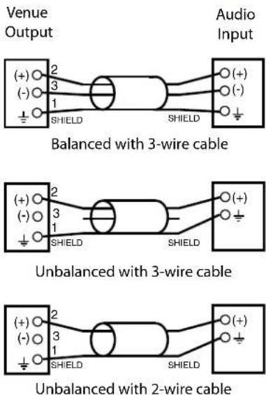
Six balanced XLR audio output jacks connect the Venue receiver to external equipment. By default, pin 2 is audio pos (+). The polarity of each output can be reversed in the LCD setup menus or with the software.
Power Input
The receiver is powered from +10 VDC to +18 VDC, with the center pin of the connector positive (+). The input is diode protected to prevent damage if the power is accidentally applied with reversed polarity. The connector includes a threaded locking sleeve.
RS-232 Port
A serial RS-232 interface is provided for setup and control of a Venue 2 system from computers or other devices using industry standard RS-232 communication links.
Antenna Inputs
The two outermost BNC connectors are provided for use with right-angle whip antennas, cables from remote antennas, or cables from another Venue receiver. DC voltage can be supplied on these connectors from an internal source to power remote RF amplifiers. The power is enabled via the front panel menu.
See the section on Antenna Use and Placement for details.
Multicoupler Outputs
The built-in antenna multicoupler provides RF distribution for the six receiver modules and a "loop thru" output at the same level to deliver the RF signal to another Venue 2 receiver. The second receiver can then feed a third receiver and so on, to create a "stack" that operates with a single pair of antennas. The result is very efficient use of rack space and a cost savings by not having to purchase a separate antenna multicoupler.
USB Port
Standard USB Version 1.1 port for setup and control of the receiver from computer systems using Windows® Vista™, Windows 7/8/10 or Mac OSX operating systems.
Hardware Installation
Receiver Modules
All modules must be within the frequency passband of the host assembly. Frequency bands are marked on the receiver modules.
When a module is set for Smart Diversity (antenna phase switching), receiver modules can be installed in any position in the mainframe chassis.
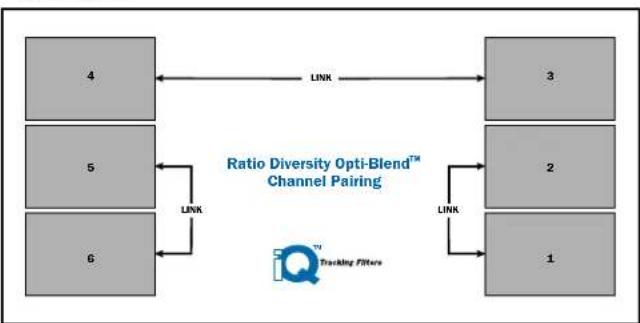
For ratio diversity operation, the module pair must be on the same frequency band and positioned adjacent to one another in the assembly as shown in the diagram on top of the mainframe chassis. This will enable Opti-Blend™ panning to mix the audio from the two modules.
flowchart
graph LR
    A["4"] <-->|LINK| B["3"]
    C["5"] <-->|LINK| D["2"]
    E["6"] <-->|LINK| F["1"]
    B --> G["Tracking Filters"]
    D --> G
    F --> G
    style A fill:#ccc
    style C fill:#ccc
    style E fill:#ccc
    style B fill:#ccc
    style D fill:#ccc
    style F fill:#ccc
    style G fill:#ccc
Installing Receiver Modules
Turn the power off.
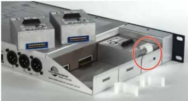
The receiver modules interface with the main assembly through multi-pin connectors on either side of the chassis. Insert the module straight down and then slide it toward the main housing to insert the connector pins. The module should sit flush against the side of the housing.
Caution: Make sure the connectors align correctly. Do not force the module onto the tab. Excessive force may damage the connectors.
Align the ridge on the retaining clip with the slot in the chassis and press the clip downward until the ridge snaps into the slot in the side panel.
natural_image
Exterior view of a server rack unit with multiple electronic modules and a highlighted cable outlet (no visible text or symbols)Removing Receiver Modules
- Turn the power off.
- Gently pull outwards on the side panel and push the top of the clip sideways to release it from the slot in the side panel.
- Pull outward on the module to release the connector and then lift it upward out of the chassis. Holes in the underside of the chassis allow you to grip the module on the top and bottom.
Rack Installation
- Mount the receiver modules in the desired rack location(s). There are no special ventilation requirements.
- Connect the antennas or coaxial cables to the antenna upper input connectors on the rear panel.
Note: The frequency bandwidth of the antennas must cover the range of the modules in use.
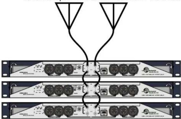
- For multiple unit installations, a "loop thru" is available to feed two or three receivers from a single antenna pair. Connect coaxial cables from the multicoupler outputs on the first receiver to the antenna inputs on the next receiver in the stack.
natural_image
Diagram of three stacked network equipment racks with connected ports and connectors (no text or symbols visible)The upper connectors are the inputs connected to the antennas on the first unit in the stack. The lower connectors are the outputs that feed the next assembly in the rack.
- Plug the power supply into a suitable outlet and plug the power connector into the Power Input Jack.
- Turn down the audio inputs on all the externally connected equipment, then connect cables to the appropriate Audio Output XLR Jacks.
Audio Outputs
Balanced XLR audio outputs on the rear panel can be used to drive balanced or unbalanced inputs at line level on any type of mixer, recorder or other type of audio equipment.

natural_image
Front view of a network equipment rack with multiple ports and connectors (no visible text or labels)Note: When the modules are paired for diversity operation, the audio will appear at both XLR jacks associated with the module pair.
Connections for Computer Interface and Serial Control
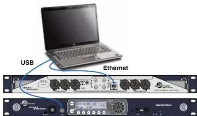
USB and Ethernet
Connection to a computer is normally made via the USB or Ethernet ports. Multiple units are easily connected using a USB hub or a network switch.
NOTE: Audio is not passed through these ports. They are used only for setup and control.

RS-232
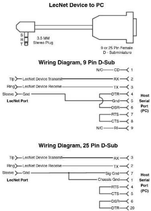
A computer or control interface can also be made via the RS-232 serial port on the rear panel. The connector is a 3.5 mm TRS type. Wiring to 9-pin and 25-pin D-Sub connectors is as follows:
flowchart
graph TD
    A["LecNet Device to PC"] --> B["3.5 MM Stereo Plug"]
    B --> C["9 or 25 Pin Female D - Subminiature"]
    D["Wiring Diagram, 9 Pin D-Sub"] --> E["Tip"] --> F["LecNet Device Transmit"]
    D --> G["Ring"] --> H["LecNet Device Receive"]
    D --> I["Sleeve"] --> J["Gnd"]
    D --> K["LecNet Port"]
    E --> L["N/C"] --> M["CD"] --> N["1"]
    F --> O["RX"] --> P["Host Serial Port (PC)"]
    G --> Q["TX"] --> R["Host Serial Port (PC)"]
    H --> S["DTR"] --> T["Host Serial Port (PC)"]
    I --> U["Gnd"] --> V["Host Serial Port (PC)"]
    J --> W["DSR"] --> X["Host Serial Port (PC)"]
    K --> Y["RTS"] --> Z["Host Serial Port (PC)"]
    L --> AA["CTS"] --> AB["Host Serial Port (PC)"]
    M --> AC["N/C"] --> AD["RI"] --> AE["Host Serial Port (PC)"]
    F --> AF["Tip"] --> AG["LecNet Device Transmit"]
    F --> AH["Ring"] --> AI["LecNet Device Receive"]
    F --> AJ["Sleeve"] --> AK["Gnd"]
    F --> AL["LecNet Port"]
    G --> AM["N/C"] --> AN["CD"] --> AO["1"]
    H --> AP["RX"] --> AQ["Host Serial Port (PC)"]
    H --> AR["TX"] --> AS["Host Serial Port (PC)"]
    H --> AT["DTR"] --> AU["Host Serial Port (PC)"]
    I --> AV["Gnd"] --> AW["Host Serial Port (PC)"]
    I --> AX["DSR"] --> AY["Host Serial Port (PC)"]
    I --> AZ["DTR"] --> BA["Host Serial Port (PC)"]
    AJ --> BB["N/C"] --> BC["RI"] --> BD["Host Serial Port (PC)"]
    AK --> BE["Gnd"] --> BF["Host Serial Port (PC)"]
    AK --> BG["Gnd"] --> BH["Host Serial Port (PC)"]
    AL --> BI["Gnd"] --> BJ["Host Serial Port (PC)"]
    AL --> BK["Gnd"] --> BL["Host Serial Port (PC)"]
    AM --> BM["N/C"] --> BN["CD"] --> BO["1"]
    AN --> BP["RX"] --> BQ["Host Serial Port (PC)"]
    AN --> BR["TX"] --> BS["Host Serial Port (PC)"]
    AN --> BT["DTR"] --> BU["Host Serial Port (PC)"]
    AO --> BV["Gnd"] --> BW["Host Serial Port (PC)"]
    AO --> BX["Gnd"] --> BY["Host Serial Port (PC)"]
    AP --> BQ
    AQ --> BQ
    AR --> BQ
    AS --> CC["Gnd"] --> CD
    AS --> DD["Gnd"] --> BE
    AT --> DE["Gnd"] --> BE
    AU --> DE
    AV --> DE
    BW --> DE
    BX --> DE
    BY --> DE
LCD Interface
When the receiver is turned on, LCD will show the model number, firmware version and serial number during the boot sequence. When the sequence is completed, the Main Window will display the status and activity of the installed receivers.
Setup and monitoring can be done directly on the front panel keypad interface. It is worthwhile to become familiar with the front panel controls even if you only use it for monitoring and to check settings.
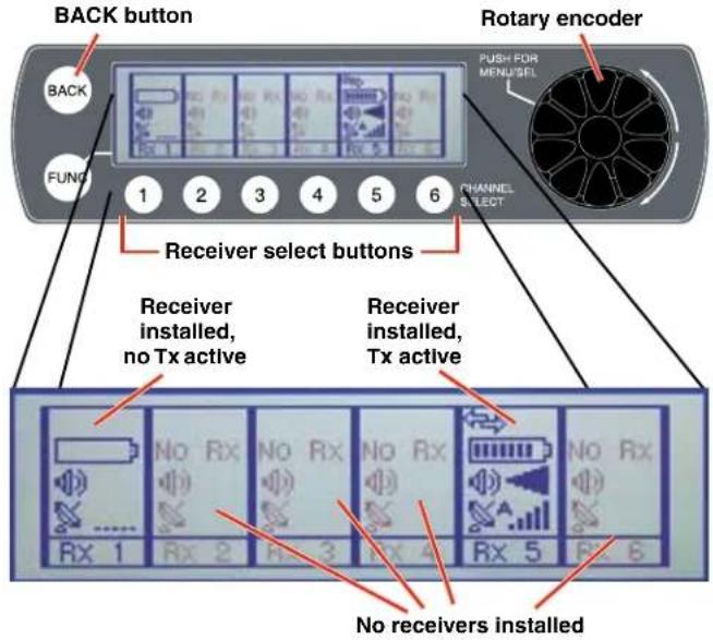
The menu structure is comprehensive but easy to navigate. Three menus provide easy access to setup screens and monitoring.
Top Menu
These are the system level settings that are common to all channels.
Rx Menu
Each receiver module has unique settings
Tx Menu
The settings for transmitters with IR ports can be configured in the receiver and then transferred to the transmitters via the IR ports.
Navigating the Menus
Three menus are provided for complete system setup:
- Top Menu for overall system settings
- RX Menu for setup of the receiver modules
• TX Menu for setup of the transmitters
Press the rotary encoder to enter the menu system. The first screen that appears is the Top Menu with links to the RX (receiver) and TX (transmitter) menus.
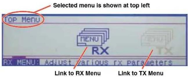
Turn the rotary encoder to navigate through the available items. The selected item appears highlighted in the center of the LCD. Press the rotary encoder to enter the setup screen for the selected item, or navigate to another menu.
The first item that appears in the RX and TX menus is a link back to the top menu.
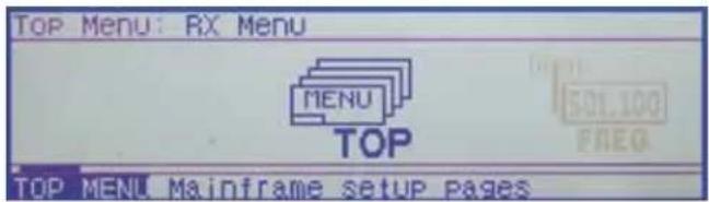
Refer to the Menu Map on the following pages for a listing and descriptions of all menu items.
Using Setup Screens
When a menu item is selected, a setup screen will open to enable adjustments and settings to be made. The setup screen may be for a simple, two-state setting like Lock/Unlock, or may provide a display that allows scrolling through the available receiver modules and options, or include multiple settings. Examples of the various screen types are presented below.
The Lock/Unlock screen is typical of the single item screens. Simply press the encoder to highlight EDIT, then rotate the encoder to select the value or setting.
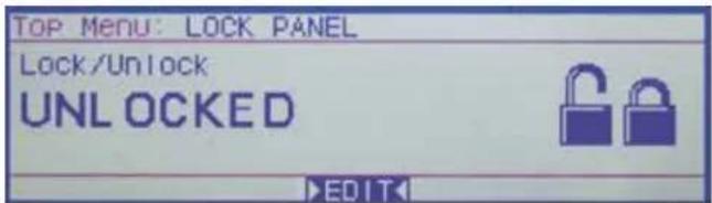
Press the rotary encoder to highlight the EDIT function and rotate the encoder to change the value.
Multiple item setup screens like the Smart NR (Smart Noise Reduction) example below allow scrolling through the options in a "stacked" arrangement.
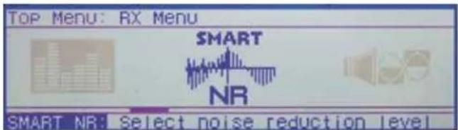
In this example, rotate the encoder to point at CHOOSE RX, then press the encoder to highlight it. Rotate the encoder to select the desired receiver.
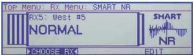
After selecting the receiver, press the encoder and rotate it to select EDIT. The noise reduction mode will be highlighted. Rotate the encoder to the desired mode.
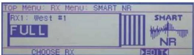
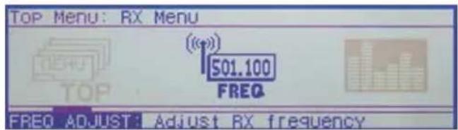
NOTE: The RX and TX Menus present multiple item setup screens like the above example, where the same setting can be made on multiple channels. Some setup screens in the Top Menu allow scrolling through multiple parameters in the same manner as the above example.
The FREQ ADJUST setup screen in the RX Menu shown here is another type of a multiple module setup screen. The difference from the previous example is that this type presents multiple settings within each receiver setup screen.
Setup Details
Direct Access to Receiver Setup
Basic adjustments to each receiver can be made in a single screen available with the numbered Receiver Select button below the frame of each receiver. These buttons operate only from the Main Window.  A setup screen opens for that channel, with RF and audio settings displayed.  Rotate the Rotary Encoder to select the function at the bottom of the screen, then press the encoder to enable it. - SEL RX highlights the function name, allowing the selected receiver to be changed by rotating the rotary encoder - EDIT enables the items on the screen to be changed. Rotate the encoder to select the item, then press the encoder to highlight it and change the value. Press the encoder again to deselect it and navigate to other items • VIEW TX displays the transmitter settings - RX MENU switches the display to the receiver setup menu  Press the encoder or BACK to deselect the item.Audio Output Levels Setup
The output level of the installed receiver modules can be adjusted in a single setup screen in the RX Menu.  Icons representing "sliders" are presented for level adjustments. The level shown for each channel is expressed in dBu. The items at the bottom of the screen are used for adjustment of the module output and for adjustment of the mixer, recorder, etc. that is connected to the receiver.  When TONE is enabled, a 1 kHz tone is produced at the output of the selected module. The tone simulates the audio level that will be produced when the transmitter on this channel is fully modulated. The modulation level of the transmitter is displayed in the Main Window and in the receiver setup screen. NOTE: The tone will not generate the displays shown below, since it is turned off when the AUDIO OUTPUT setup screen is exited.   Modulation (audio level)   Full modulation (onset of limiting) Transmitters also have modulation indicators such as the LEDs on the SM Series models.  Modulation LEDs (audio level) Signal Level -20 LED -10 LED| Less than -20 dB | Off | Off | |
| -20 dB to -10 dB | Green | Off | |
| -10 dB to +0 dB | Green | Green | |
| +0 dB to +10 dB | Red | Green | |
| Greater than +10 db | Red | Red |
Optimizing the Signal to Noise Ratio
Given the information above, the optimum signal to noise ratio is achieved when the least amount of gain is applied to the signal, since gain (amplification) is the source of noise buildup. The transmitter input preamp is the low noise gain stage at the beginning of the signal chain. The ideal setup is to have this be the only gain stage, and subsequent stages be at unity (zero gain/loss). Attenuation (loss) in a subsequent stage is OK unless it requires another gain stage to compensate for it. 1) Set the transmitter gain so that full modulation is achieved on louder peaks in the audio 2) Set the receiver output level as high as possible without overloading the connected device it is feeding (mixer, recorder, etc.). Use a line level input on the connected device whenever it is available. This minimizes the gain needed in the device and maximizes the signal to noise ratio.Diversity Pairing
Navigate to the DIVERSITY LINK screen in the RX Menu. Press the encoder to open the setup screen.  Selected receiver pair marked by brackets  Select CHOOSE RX on the bottom of the screen and rotate the encoder to select the desired pair. Highlight EDIT and rotate the encoder to make the setting.  The receiver icons are arranged so that adjacent units are paired when the RATIO mode is set. When the SWITCHED mode is set, the units operate independent of one another.Talkback Setup
Talkback is a special function that re-directs the audio output of the transmitter in use to a different receiver module when a button is pressed on the transmitter. The normal use is to provide a "com" channel so the person using the transmitter can have a direct line to the crew or production staff. The HH hand held transmitter provides a programmable switch on the housing that can be configured for this function. The switch function is configured from the LCD menu on the transmitter.  As long as the button is held in, the audio will appear at the designated talkback channel rather than the channel used for program audio. A simple setup screen in the Venue 2 receiver makes it easy to designate channels with this function enabled and which output will deliver the talkback audio.   If multiple channels have talkback enabled and share the same talkback channel, the audio outputs from all of them will appear simultaneously (mixed) at the talkback output channel if multiple buttons are pressed at the same time.Group Tuning
Up to 32 frequencies can be stored in each of four groups labeled U, V, W and X. The groups are commonly used to make setup easier for specific locations and purposes. A setup screen is provided to assign each receiver to a particular group. The group frequencies can be edited by selecting MODIFY GRP. About Active Alerts
When a system fault occurs, such as a short in an antenna input when antenna power is turned on, the alert LED on the front panel will start blinking.  NOTE: In the case of shorted antenna input, the antenna power will also be turned off. When the Alert LED is blinking, navigate to the SYSTEM INFO screen on the LCD to read and reset the alert message.   A description of the fault will appear in the display. If there is more than one fault, the highest priority of most recent will appear. When it is reset, the next one in the list will appear.Top Menu SYSTEM INFO
Firmware and hardware versions and the serial number of the unit is listed in the SYSTEM INFO screen.  Resetting to Factory Defaults
Navigate to SYSTEM INFO in the Top Menu and press the encoder to enter the screen.  Highlight SYSTEM DEFAULT and press the encoder.  Highlight OK in the next pop-up screen and press the encoder to restore the factory default settings. The default settings are as follows:| Level | +00 dBu |
| Phase | NORMAL |
| TxBatt | AA ALK |
| SmartNR | NORMAL |
| Compat | Dig. Hybrid |
| Tuning | NORMAL MODE |
| DivMode | Switched |
| LockSet | NOT LOCKED |
| RxCh | 8, 0 |
IR Transmitter Setup
The IR (infrared) port simplifies transmitter setup by sending the settings saved in the receiver to an IR enabled transmitter. The IR port is located on the receiver front panel next to the power switch.  The transfer is initiated by the receiver. Navigate to the SETTINGS item in the TX MENU and press the encoder to open the setup screen. Select the desired transmitter channel.   After the transmitter channel is selected, choose either SEND FREQ to send only the frequency or SEND ALL to send all settings that appear on the LCD.  Select either SEND FREQ or SEND ALL Hold the transmitter with its IR port facing the receiver front panel within two feet or so. Press the encoder to start the transfer. The receiver LCD will display a message during the transfer.  Confirmation that the transfer has been completed will be displayed on the transmitter LCD.Smart Tune™
Clear frequencies can be discovered automatically using the SmartTune™ utility. Navigate to SMART TUNE in the TOP MENU and press the encoder. A listing of the installed receiver modules will appear.   The number of scan passes can be set from 1 to 10. A single pass will identify xed RF signals such as television broadcasts. Multiple passes stand a better chance of catching intermittent signals or those that fluctuate in strength fairly often. Of course, multiple scans takes more time, but it is a good idea if there is time for it. Use the 6 buttons under the LCD to select the channels to be included in the scans. Press each button to check the corresponding box in the display (enable the channel) and press the button again to remove the check mark (disable the channel). Select BEGIN and press the encoder to start the scanning process. RX1 (channel 1) will be scanned first, and when a clear frequency is identified, a pop up screen will appear displaying the results and a prompt to turn on a transmitter on the newly discovered frequency. An option to send the settings to an IR enabled transmitter is also presented on the pop up screen.Manual Scanning
Spectrum scanning can be conducted manually to research RF activity. Navigate to the SCAN item in the TOP MENU and press the encoder. Then select the receiver to use for the scan the icon shown below.   After selecting the receiver to use for the scan, select START and press the encoder. The START item will change to STOP while the scanning is taking place.  The scanning will build a graphical representation of the RF activity within the tuning range of the receivers. The scanning will take place from left to right and continue repeating until STOP is selected and the encoder is pressed, and the scanning is paused. While paused, the spectrum can be manually explored by scrolling through the display. Select and highlight SCROLL and rotate the encoder to move the cursor through the scan results.  For a closer view of the scan data, deselect SCROLL, then select ZOOM IN and press the encoder. The display with magnify the scan results and the screen can be scrolled in a close-up view. bar
| Time | Frequency | |------|---------| | 0 | 501.950 | | 1 | 501.950 | | 2 | 501.950 | | 3 | 501.950 | | 4 | 501.950 | | 5 | 501.950 | | 6 | 501.950 | | 7 | 501.950 | | 8 | 501.950 | | 9 | 501.950 | | 10 | 501.950 | | 11 | 501.950 | | 12 | 501.950 | | 13 | 501.950 | | 14 | 501.950 | | 15 | 501.950 | | 16 | 501.950 | | 17 | 501.950 | | 18 | 501.950 | | 19 | 501.950 | | 20 | 501.950 | | 21 | 501.950 | | 22 | 501.950 | | 23 | 501.950 | | 24 | 501.950 | | 25 | 501.950 | | 26 | 501.950 | | 27 | 501.950 | | 28 | 501.950 | | 29 | 501.950 | | 30 | 501.950 | | 31 | 501.950 | | 32 | 501.950 | | 33 | 501.950 | | 34 | 501.950 | | 35 | 501.950 | | 36 | 501.950 | | 37 | 501.950 | | 38 | 501.950 | | 39 | 501.950 | | 40 | 501.950 | | 41 | 501.950 | | 42 | 501.950 | | 43 | 501.950 | | 44 | 501.950 | | 45 | 501.950 | | 46 | 501.950 | | 47 | 501.950 | | 48 | 501.950 | | 49 | 501.950 | | 50 | 501.950 | | 51 | 501.950 | | 52 | 501.950 | | 53 | 501.950 | | 54 | 501.950 | | 55 | 501.950 | | 56 | 501.950 | | 57 | 501.950 | | 58 | 501.950 | | 59 | 501.950 | | 60 | 501.950 | | 61 | 501.950 | | 62 | 501.950 | | 63 | 501.950 | | 64 | 501.950 | | 65 | 501.950 | | 66 | 501.950 | | 67 | 501.950 | | 68 | 501.950 | | 69 | 501.950 | | 70 | 501.950 | | 71 | 501.950 | | 72 | 501.950 | | 73 | 501.950 | | 74 | 501.950 | | 75 | 501.950 | | 76 | 501.950 | | 77 | 501.950 | | 78 | 501.950 | | 79 | 501.950 | | 80 | 501.950 | | 81 | 501.950 | | 82 | 501.950 | | 83 | 501.950 | | 84 | 501.950 | | 85 | 501.950 | | 86 | 501.950 | | 87 | 501.950 | | 88 | 501.950 | | 89 | 501.950 | | 90 | 501.950 | | 91 | 501.950 | | 92 | 501.950 | | 93 | 501.950 | | 94 | 501.950 | | 95 | 501.950 | | 96 | 501.950 | | 97 | 501.950 | | 98 | 501.950 | | 99 | 501.950 | | ... (approximate values) for the rightmost bars are not explicitly labeled in the chart title but are inferred from the visual data labels on the left and right axes.Firmware Update
Firmware updates are detailed in the Wireless Designer software help file. Launch the software and click on Online Help, then on Venue2 Receiver Setup and Monitoring, then on the item for updating firmware. System Restore
If a firmware update fails, the receiver will need to be restored with the following procedure. Review the Firmware Update Procedure in the online help before proceeding. 1) Remove power from the VRM2 - you have to actually remove the DC power cable on the rear panel of the unit. 2) Using a paper clip, or similar object, depress the small, white, unmarked button recessed into the front panel to the left of the headphone jack. This is the Recovery Mode button.  3) While keeping the Recovery Mode button depressed, plug in the DC power jack to the rear of the unit. The LCD will light up but be blank. 4) The unit will now be in the "Recovery Mode." Release the Recovery Mode button. 5) Open Wireless Designer, and proceed to update the firmware using the normal steps, EXCEPT be sure to click and mark the "Recovery Mode" check box at the bottom of the screen.  NOTE: The sample image above shows the DR receiver front panel, with a different location of the Recovery Mode button 6) Follow the on-screen instructions. If the firmware update is successful, an on-screen message will appear as confirmation. When the process is complete, turn the receiver off and then back on again to verify that the unit is operational.Wireless Designer Software
Download the Wireless Designer software installer from the web sites under the SUPPORT tab at: http://www.lectrosonics.com/US Wireless Designer only needs to be installed the first time the software is used. Once the software is installed, updates are available by simply clicking on an item in the Help Menu. NOTE: If Wireless Designer is already installed, you must uninstall it before attempting to install a new copy.Firmware Update Instructions
Firmware updates are made with a file downloaded from the web site and the Venue 2 connected via USB. The USB port on requires a micro-B male plug on the connecting cable. The other end of the cable would normally be a USB A-Type male connectorto fit the most common type of USB jack used on computers. Refer to Help in Wireless Designer software for the procedure.TOP MENU
 DETECT takes an inventory of the receiver modules installed in the mainframe and displays the results in an on-screen table.  SMART TUNE is an automatic process that scans the tuning range of all modules and automatically finds clear frequencies. The screen prompts the operator to set up transmitters one at a time to the newly discovered frequencies and turn them on before proceeding.  SPECTRUM SCAN launches a manual scanning procedure where each receiver module is scanned one at a time, with the results presented in a graphical display.  LOCK PANEL prevents changes from being made with the front panel controls.  BACK LIGHT adjusts the brightness of the LCD. Four different levels are available.  ANTENNA POWER turns the DC bias power on the antenna inputs off and on. The DC bias is used to power remote amplifiers used at the antenna end of long coaxial cable runs.  NETWORK SETUP provides screens to define the parameters for network protocol and connections.  RS232 SETUP provides a screen where the baud rate can be set from 9600 to 115200.  COMMAND VIEW opens a screen that displays the commands received from a remote control device or computer and the replies sent back by the receiver.  SYSTEM INFO displays the receiver serial number, hardware and firmware revisions, and the active alerts. Active alerts shown on this screen are error messages that list of faults in the receiver. When a fault occurs, ED on the right side of the front panel will ping the operator to view this screen.Menu Map
flowchart
graph TD
    A["TOP MENU"] --> B["FX"]
    B --> C["TX"]
    C --> D["DETECT SMART"]
    D --> E["SMART"]
    E --> F["TUNE"]
    G["TX MENU"] --> H["SETTINGS"]
    H --> I["TX BATTERY"]
    J["RX MENU"] --> K["FREQ ADJUST"]
    K --> L["A"]
    L --> M["UDIO LEVEL"]
TX MENU
NOTE: Some items in this menu work only with Lectrosonics transmitters.  TOP MENU links back to the Top Menu for overall system setup.  SETTINGS is used to get settings from and send settings to a Lectrosonics transmitter on each channel. The LCD shows a listing of the frequency and nine configuration settings on a single screen. NOTE: The transmitter settings can be made in the receiver and then transferred via IR (infrared) to the transmitter if it is so equipped. Later model Lectrosonics transmitters offer this feature.  TX BATTERY selects the battery type used in each transmitter.  TX AUDIO GAIN adjusts the input gain of each channel to match the microphone or instrument level delivered to the transmitter to optimize the signal to noise ratio and minimize distortion. flowchart
graph LR
    A["SPECTRUM SCAN"] --> B["LOCK PANEL"]
    B --> C["BACK LIGHT"]
    C --> D["ANTENNA POWER"]
    D --> E["NETWORK SETUP"]
    E --> F["RS232 SETUP"]
    F --> G["COMMAND VIEW"]
    G --> H["SYSTEM INFO"]
flowchart
graph LR
    A["TX AUDIO GAIN"] --> B["LF ROLLOFF"]
    B --> C["TX PHASE"]
    C --> D["PROG SWITCH"]
    D --> E["AUTO ON"]
    E --> F["TX PANEL LOCK"]
    F --> G["BATT TIMER"]
    G --> H["TX BACKLIGHT"]
    H --> I["STEP SIZE NARROW BAND"]
flowchart
graph LR
    A["SMART NR"] --> B["PHASE"]
    B --> C["RX LINK"]
    C --> D["COMPAT MODE"]
    D --> E["TALKBACK GROUP"]
    E --> F["TUNING"]
    F --> G["SQUELCH BP"]
    G --> H["MODULE POWER"]
RX MENU
 TOP MENU links back to the Top Menu for overall system setup.  FREQ ADJUST opens a setup screen to manually select the frequency of each receiver module. NOTE: The setting for 100 or 25 kHz frequency increments is in the TX Menu under STEP SIZE, selectable on a per channel basis.  AUDIO LEVEL is used to adjust the output level of each receiver. The built-in tone generator is also enabled in this screen.  SMART NR sets the desired noise reduction mode for each channel: NORMAL, FULL or OFF.  PHASE sets the polarity (phase) of each output to the desired value: NORMAL or INVERTED.  RX LINK (DIVERSITY LINK) selects adjacent receivers to be paired for Ratio Diversity operation, or to be operated individually with Antenna Phase Switching Diversity.  COMPAT MODE sets the DSP-based compatibility mode for each channel. NOTE: If your Lectrosonics Transmitter is set to Nu Hybrid Compatibility Mode, set the receiver to Euro Digital Hybrid Wireless® (EU HYBR). Make certain the COMPAT mode is set to match the mode in the transmitter for optimum audio quality.  TALKBACK enables the Talkback Mode on the desired channels and selects the output channel for the talkback audio.  GROUP TUNING opens setup and editing screens to select and modify user defined frequency groups U, V, W and X, or NONE for each receiver module.  SQUELCH BP bypasses the squelch (muting) function on a per module basis for diagnostic purposes. CAUTION: Reduce the gain or volume level of the sound system or recorder before bypassing the squelch. Very loud noise will be present at the bypassed channel.  MODULE POWER turns the power ON or OFF on each receiver module. Normally used to prolong operating time when the receiver is powered by battery.Connecting to a Network
A basic network is composed of several devices: - Router or server - Ethernet switch - Client devices An example of a simple network is a modem used in a home for internet access via a telephone or cable TV connection. There are actually three different devices built into the box that is typically called the “modem.” - Modem - connects to the ISP (Internet Service Provider) via telephone or cable TV service - Router - creates the network; identifies and organizes the connected devices and allows participation in the network - Ethernet switch - synchronizes the network traffic between multiple devices; usually 4 cabled connections and one WiFi wireless connection in a typical home modem A network connection from a computer to the Venue 2 receiver can be made via a network using Wireless Designer™ software. flowchart
graph TD
    A["Router/Server"] --> B["Ethernet Switch"]
    B --> C["Venue 2 Receiver"]
    B --> D["Other Devices"]
IP Address Assignment
An IP address for the Venue 2 receiver can be assigned by a network administrator, or obtained from the server or router automatically using DHCP enable in the receiver.Enable DHCP with the LCD interface:
Press the rotary encoder and navigate to the Top Menu then to NETWORK SETUP. Press the encoder and highlight SELECT PARAMETER. Navigate to the DHCP Enable item. Highlight EDIT and rotate the encoder to select YES on the display. Press the BACK button several times to return to the main window.Enable DHCP with With Wireless Designer and a USB connection:
Connect the computer to the Venue 2 receiver via the USB port. Launch Wireless Designer. Turn on the Venue 2 receiver, or turn it off and back on if it's already turned on. Wait for the receiver to fully boot up (the main window appears). In Wireless Designer, click on Connect (Live) in the upper left corner of the screen, then on Connect via USB... A dialog box opens and the receiver will appear with its serial number. Click on the receiver and then on OK to open the control panel. Click on Settings, then Network, then click in the checkbox next to DHCP Enable to make sure a check mark appears.  Disconnect Wireless Designer from the receiver. Click on Connect (Live)... in the top left of the control panel, then click on Disconnect From and then on the receiver name that appears.Connect to a Network
NOTE: Make sure an IP address has been assigned to the receiver before trying to connect to a network. Connect the network cable to the ethernet port on the receiver, then cycle the receiver power off and back on. The IP address will be assigned to the receiver by the router/server when the receiver boots up. Look at the IP address in the LCD screen where you enabled DHCP, or you can re-connect to the receiver via USB and view the IP address on the software control panel screen where you enabled DHCP in the check box. Jot down the IP address. Open Wireless Designer and click on Connect via Network... Enter the IP address and click on Search. When the receiver appears in the dialog box, click on OK to enter the control panel.Multi-channel System Checkout
Interference can result from a wide variety of sources including TV station signals, other wireless equipment in use nearby, or from intermodulation within a multi-channel wireless system itself. Regardless of how the frequencies were coordinated, a final checkout procedure is always a good idea. Scanning with the RF spectrum analyzer built into the Venue 2 system will identify external RF signals, but it does not address the compatibility of the selected frequencies. Wireless Designer software provides an excellent frequency coordination function that integrates scan data and carriers into the calculations. The results are highly reliable, but if time allows, it is also a good idea to conduct a final test with the following procedure.1. Set up the system for testing.
Place antennas in the position in which they will be used and connect to the receivers. Place transmitters about 3 to 5 feet apart, about 25 to 30 feet from the receiver antennas. If possible, have all other equipment on the set, stage or location turned on as well, especially any mixing or recording equipment that will be used with the wireless system.2. Set all receivers on clear channels.
Turn on all receivers, but leave the transmitters off. Observe at the RF signal strength indicator for each receiver module. If a signal is present, change the frequency to a clear channel where no signal is indicated. If a completely clear channel cannot be found, select the frequency with the lowest RF level indication. Once all receiver modules are on clear channels, go to step 3.3. Turn each transmitter on one at a time.
Start with all transmitters turned off. As you turn on each one, look at the matching receiver to verify a strong RF signal is received. Then, look at the other receivers and see if one of them is also picking up the signal. Only the matching receiver should indicate a signal. Change frequencies on either system slightly until all channels pass this test, then check again to see that all channels are still clear as done in step 2.4. Turn each transmitter off one at a time.
With all transmitters and receivers turned on, turn each transmitter off one at a time, in turn, and look at the RF level indicator on the matching receiver module. The RF level should disappear or drop to a very low level. If it does not, change frequency on that receiver and transmitter and try it again. When a clear frequency is found, turn the transmitter on and move on to the next channel. IMPORTANT: Any time a frequency is changed on any of the systems in use, you must start at the beginning and go through this procedure again for all systems. With a little practice, you will be able to do this quickly and wave yourself some grief.Antennas
Use and Placement
The Venue 2 mainframe is designed for rack mounting. Although it can be operated with two whip antennas, it is best to use remote antennas such as the SNA600 or ALP Series for optimum reception. Position the remote antennas at least three or four feet apart and not within three or four feet of large metal surfaces. If this is not possible, try to position the antennas so that they are as far away from the metal surface as is practical. It is also good to position them so that there is a direct "line of sight" between the transmitter and the receiver antennas. In situations where the operating range is less than about 100 feet, the antenna positioning is much less critical. The length and type of cabling between antennas and the system, however, is critical. Long cable runs can experience significant signal loss. Lectrosonics offers in-line RF amplifiers to compensate for this signal loss. Contact your dealer or the factory for more information. A wireless transmitter sends a radio signal out in all directions. This signal will often bounce off nearby walls, ceilings, etc. and a strong reflection can arrive at the receiver's antennas along with the direct signal. If the direct and reflected signals are out of phase with each other and similar in strength, a cancellation or "drop-out" may occur. A dropout can sound like audible noise (hiss, swishing or a "shhht" sound), or in severe cases, may result in a complete loss of both the carrier and the sound. Moving the transmitter even a few inches can change the sound of the dropout, or may even eliminate it. A dropout situation also may be either better or worse as a crowd fills or leaves the room. The receiver offers two different diversity reception methods which overcome most dropout problems. In the event, however, that you do encounter a dropout problem, first try moving one of the remote antennas at least three or four feet from its current location. If dropouts are still a problem, try moving the antennas to entirely different locations. Lectrosonics transmitters radiate power very efficiently, and the receivers are very sensitive, which reduces dropouts to an insignificant level. If, however, you do encounter dropouts frequently, call the factory or consult your dealer. There is probably a simple solution.Using Remote Antennas
Remote antennas can be placed at a distance from the receiver to optimize reception. To overcome loss in long coaxial cable runs, a Lectrosonics UFM Series inline RF filter/amp should be positioned at the far end of the coaxial cable, close to the antenna. With the amplifier in this position, g ain is applied ahead of the loss to maximize the signal to noise ratio of the antenna system. NOTE: It is best practice to enable this DC power ONLY when a UFM remote amplifier or active antenna is used. Some antennas may present a short to the power supply. While the power supply is fused and it is unlikely that damage would occur, it is always best to disable the DC when it is not in use.Front Mounted Antennas
The internal coaxial cables and connectors can be moved to the front panel if so desired, using small flat blade and Phillips screwdrivers. WARNING: Always unplug the receiver before performing this procedure.Step 1
Remove receiver modules, plastic end connector covers and front panel jack covers on both sides of the receiver. natural_image
Interior view of an electronic device showing a circuit board with ports and a green component (no visible text or symbols)Step 2
Remove the front panel hole caps.  Locking tabs on opposite sides The hole caps have locking tabs to retain the cap when installed. Use a flat blade screwdriver and depress the locking tabs on one side of the hole cap while pushing outward on the cap. The cap will move outward slightly to release the tabs on one side of the plug. natural_image
Close-up of a mechanical component with a cylindrical shaft inserted into a housing (no visible text or symbols)natural_image
Close-up of a circular mechanical component with a central hole (no visible text or symbols)natural_image
Close-up of a blue and silver electronic device with a circular component, no visible text or symbolsStep 3
Remove the four screws holding the chassis cover, then remove the cover by lifting the rear up. CAUTION: The exposed components on the circuit board are sensitive to static shock. Wear an anti-static wrist strap grounded to the housing of the receiver to avoid damaging the components. natural_image
Blue and white photo of a blue band with attached metal clip (no text or symbols visible)natural_image
Close-up of a computer tower with visible ports and connectors, marked by red circles (no text or symbols present)natural_image
Interior view of an electronic device showing a green circuit board with gold contacts and components, no visible text or symbols.Step 4
Remove the nuts and washers from the upper two BNC connectors and route the coaxial cables to the front panel. natural_image
Interior view of an open electronic device showing a green circuit board with various components and wiring (no visible text or symbols)Step 5
Align the flats on the BNC connectors with the flats in the holes in the front panel and secure them with the lock washers and nuts. natural_image
Close-up of a metallic connector attached to a dark metal panel (no visible text or symbols)Step 6
Route the coaxial cables underneath the front panel jack covers, replace the covers and tighten the screws. natural_image
Close-up of a white electronic device with a green circuit board and cable, showing internal components and a red diagonal line (no text or symbols visible)Step 7
Turn the receiver over and make sure the tabs on the jack covers sit flush with the bottom of the receiver chassis. natural_image
Close-up of a device panel with three red-circled annotations and a black button labeled 'Cable software version' (no readable text beyond labels)Step 8
Press the hole caps into the holes on the rear panel. natural_image
Close-up of electronic equipment components including USB ports, Ethernet, and network ports (no readable text or symbols)Step 9
The coaxial cables should route toward the front of the receiver as shown so the cable fits loosely under the jack covers. Finger tighten the SMA connectors on the circuit board. natural_image
Close-up of a green printed circuit board with visible traces and components (no readable text or symbols)Step 10
Replace the chassis cover. Insert the tabs on the front of the cover first, then gently press outward on the rear panel to allow the cover to slip into place and tighten the four screws securing the cover. natural_image
Interior view of an electronic device showing a green circuit board with gold contacts and internal components (no visible text or symbols)Accessories and Common Replacement Parts
Remote Antennas
ALP Series LPDA (log periodic dipole array) models SNA600A folding dipole antenna ALP Kit mounting hardwareCoaxial Cable
ARG2 coaxial cable - 2 ft. length ARG15 coaxial cable - 15 ft. length ARG25 coaxial cable - 25 ft. length ARG50 coaxial cable - 50 ft. length ARG100 coaxial cable - 100 ft. lengthCoaxial RF Amplifier
UFM230 broadband RF amplifier - 230 MHz BW UFM50 narrowband RF amplifier - 50 MHz BWCommon Replacement Parts
DCR15/4AU power supply 24088 Pre-coordinated frequency groups (folded sheet) 21710-1 LecNet Cable for AMX/Crestron control 21529-1 LecNet Cable for RS-232 control 21713 USB Cable - 6 ft. long MC65 Cable - 1/4 inch male TRS to mini male TRS P1196 white receiver retaining clip P1204 receiver connector coverUSB Cable
#21713 - Cable, MB USB A2B - 6ft. length   natural_image
Coiled black cable with connectors and metallic fittings, no visible text or symbolsnatural_image
Coiled USB cable with two connectors, no visible text or symbols on the cable itselfSpecifications
Operating Frequencies - Host Mainframe VRM2WBL: Tunes to bands A1, B1, B2, C1 VRM2WBM: Tunes to bands B1, B2, C1, C2 Operating Frequencies - VRT2 Module Band A1: 470.100 - 537.575 MHz (blocks 470, 19, 20) Band B1: 537.600 - 614.375 MHz (blocks 21, 22, 23) Band B2: 563.200 - 639.900 MHz (blocks 22, 23, 24) Band C1: 614.400 - 691.175 MHz (blocks 24, 25, 26) Band C2: 640.000 - 716.700 MHz (blocks 25, 26, 27) Frequency selection: Up to 3072 frequencies Frequency selection steps: Selectable; 100 kHz or 25 kHz Digital latency: • 1.5 mS (receiver only - hybrid mode) • 3.0 mS (receiver and transmitter in hybrid mode) • 3.0 mS (receiver only - analog compatibility mode) The 3.0 mS latency in analog compatibility mode time aligns the audio from analog and hybrid transmitters when they are used together in a Venue system. Wideband Multicoupler: Built in antenna multicoupler covers a 230 MHz range. Pilot tone: 25 to 32 kHz; 5kHz deviation; unique pilot tone frequency for each selected carrier frequency (Hybrid mode) Deviation: ±75 kHz (max) (Hybrid mode) Receiver Type: Triple conversion superheterodyne Frequency Stability: ±0.001% Multicoupler Bandwidth: 470 - 691 MHz or 537 - 768 MHz Front End Bandwidth: \- iQ filter wide mode: 15 MHz • iQ filter narrow mode: 10 MHz Sensitivity (20 dB Sinad): 0.9 uV AM Rejection: >60 dB, 2 uV to 1 Volt Image and Spurious Rejection: 85 dB Third Order Intercept: \- iQ filter wide mode: +5 dBm \- iQ filter narrow mode: +12 dBm \- Antenna Combining Phase Diversity Methods: switching \- Opti-blend ^TM1 ratio diversity FM Detector: Digital pulse counting detector @ 300 kHz Audio Performance (overall system): Frequency Response: 32 Hz to 20 kHz (+/-1dB), overall system (400 Series mode) THD: 0.2% (typical) (400 Series mode) SNR at receiver output (dB) In Hybrid operating mode:| SmartNR | No limiting | w/ Limiting |
| OFF | 103.5 | 108.5 |
| NORMAL | 107.0 | 111.5 |
| FULL 108.5 | 113.0 |
Service and Repair
If your system malfunctions, you should attempt to correct or isolate the trouble before concluding that the equipment needs repair. Make sure you have followed the setup procedure and operating instructions. Check the interconnecting cables and then go through the TROUBLESHOOTING section in this manual. We strongly recommend that you do not try to repair the equipment yourself and do not have the local repair shop attempt anything other than the simplest repair. If the repair is more complicated than a broken wire or loose connection, send the unit to the factory for repair and service. Don't attempt to adjust any controls inside the units. Once set at the factory, the various controls and trimmers do not drift with age or vibration and never require readjustment. There are no adjustments inside that will make a malfunctioning unit start working. LECTROSONICS' Service Department is equipped and staffed to quickly repair your equipment. In warranty repairs are made at no charge in accordance with the terms of the warranty. Out-of-warranty repairs are charged at a modest flat rate plus parts and shipping. Since it takes almost as much time and effort to determine what is wrong as it does to make the repair, there is a charge for an exact quotation. We will be happy to quote approximate charges by phone for out-of-warranty repairs.Returning Units for Repair
For timely service, please follow the steps below: A. DO NOT return equipment to the factory for repair without first contacting us by letter or by phone. We need to know the nature of the problem, the model number and the serial number of the equipment. We also need a phone number where you can be reached 8 A.M. to 4 P.M. (U.S. Mountain Standard Time). B. After receiving your request, we will issue you a return authorization number (R.A.). This number will help speed your repair through our receiving and repair departments. The return authorization number must be clearly shown on the outside of the shipping container. C. Pack the equipment carefully and ship to us, shipping costs prepaid. If necessary, we can provide you with the proper packing materials. UPS is usually the best way to ship the units. Heavy units should be "double-boxed" for safe transport. D. We also strongly recommend that you insure the equipment, since we cannot be responsible for loss of or damage to equipment that you ship. Of course, we insure the equipment when we ship it back to you. Mailing address: Shipping address: Telephone: Lectrosonics, Inc. Lectrosonics, Inc. (505) 892-4501 PO Box 15900 561 Laser Rd., Suite 102 (800) 821-1121 Toll-free Rio Rancho, NM 87174 Rio Rancho, NM 87124 (505) 892-6243 Fax USA USA Web: www.lectrosonics.com E-mail (general): sales@lectrosonics.com E-mail (service): service.repair@lectrosonics.com Mailing address Lectrosonics Canada 720 Spadina Ave Suite 600 Toronto, Ontario, M5S 2T9 Telephone: (877) 753-2876 (416) 596-2202 (416) 596-6648 Fax E-mail (service): colinb@lectrosonics.com joeb@lectrosonics.comLIMITED ONE YEAR WARRANTY
The equipment is warranted for one year from date of purchase against defects in materials or workmanship provided it was purchased from an authorized dealer. This warranty does not cover equipment which has been abused or damaged by careless handling or shipping. This warranty does not apply to used or demonstrator equipment. Should any defect develop, Lectrosonics, Inc. will, at our option, repair or replace any defective parts without charge for either parts or labor. If Lectrosonics, Inc. cannot correct the defect in your equipment, it will be replaced at no charge with a similar new item. Lectrosonics, Inc. will pay for the cost of returning your equipment to you. This warranty applies only to items returned to Lectrosonics, Inc. or an authorized dealer, shipping costs prepaid, within one year from the date of purchase. This Limited Warranty is governed by the laws of the State of New Mexico. It states the entire liability of Lectrosonics Inc. and the entire remedy of the purchaser for any breach of warranty as outlined above. NEITHER LECTROSONICS, INC. NOR ANYONE INVOLVED IN THE PRODUCTION OR DELIVERY OF THE EQUIPMENT SHALL BE LIABLE FOR ANY INDIRECT, SPECIAL, PUNITIVE, CONSEQUENTIAL, OR INCIDENTAL DAMAGES ARISING OUT OF THE USE OR INABILITY TO USE THIS EQUIPMENT EVEN IF LECTROSONICS, INC. HAS BEEN ADVISED OF THE POSSIBILITY OF SUCH DAMAGES. IN NO EVENT SHALL THE LIABILITY OF LECTROSONICS, INC. EXCEED THE PURCHASE PRICE OF ANY DEFECTIVE EQUIPMENT. This warranty gives you specific legal rights. You may have additional legal rights which vary from state to state.
- Venue 2 Modular Receiver
- With Built-in Multicoupler
- Two versions available:
- Hardware/Software Installation and Configuration
- Essential Setup Steps for Operation
- CE1313 Ⓞ
- Declaration of Conformity
- Table of Contents
- FCC Notice:
- Introduction
- The Host Assembly
- iQ Front-end Filtering
- Wireless Designer Software
- Important Safety Instructions
- Front Panel
- POWER Button
- Function Button
- BACK Button
- LCD Screen
- Receiver Select Buttons
- PUSH FOR MENU/SELECT Rotary Control
- PHONES Jack and LEVEL Control
- Rear Panel
- Receiver Modules
- Audio Outputs
- Power Input
- RS-232 Port
- Antenna Inputs
- Multicoupler Outputs
- USB Port
- Hardware Installation
- Installing Receiver Modules
- Caution: Make sure the connectors align correctly. Do not force the module onto the tab. Excessive force may damage the connectors.
- Removing Receiver Modules
- Rack Installation
- Connections for Computer Interface and Serial Control
- USB and Ethernet
- LCD Interface
- Top Menu
- Rx Menu
- Tx Menu
- Navigating the Menus
- Using Setup Screens
- Setup Details
- Direct Access to Receiver Setup
- Audio Output Levels Setup
- Optimizing the Signal to Noise Ratio
- Diversity Pairing
- Talkback Setup
- Group Tuning
- About Active Alerts
- Top Menu SYSTEM INFO
- Resetting to Factory Defaults
- IR Transmitter Setup
- Smart Tune™
- Manual Scanning
- Firmware Update
- System Restore
- Firmware Update Instructions
- Menu Map
- Connecting to a Network
- IP Address Assignment
- Enable DHCP with the LCD interface:
- Enable DHCP with With Wireless Designer and a USB connection:
- Connect to a Network
- Multi-channel System Checkout
- Set up the system for testing.
- Set all receivers on clear channels.
- Turn each transmitter on one at a time.
- Turn each transmitter off one at a time.
- Antennas
- Use and Placement
- Using Remote Antennas
- Front Mounted Antennas
- Step 1
- Step 2
- Step 3
- Step 4
- Step 5
- Step 6
- Step 7
- Step 8
- Step 9
- Step 10
- Accessories and Common Replacement Parts
- Remote Antennas
- Coaxial Cable
- Coaxial RF Amplifier
- Common Replacement Parts
- USB Cable
- Specifications
- Service and Repair
- Returning Units for Repair
- LIMITED ONE YEAR WARRANTY
Brand : Lectrosonics
Model : Venue 2
Category : Receiver