
GH06 - Tripod E-Image - Free user manual and instructions
Find the device manual for free GH06 E-Image in PDF.


| Product Type | Tripod Fluid Head System |
| Brand | E-Image |
| Model | GH06 |
| Bowl Size | 75mm |
| Load Capacity | 6 kg (13.2 lbs) |
| Net Weight (Head) | 1.6 kg (3.5 lbs) |
| Counterbalance | Adjustable |
| Drag System | Variable pan and tilt drag |
| Tilt Range | +90° to -60° |
| Temperature Range | -40°C to 80°C |
| Pan Handle | Included, adjustable length |
| Quick Release Plate | GP1-style with safety lock |
| Bubble Level | Integrated |
| Tripod Material | Aluminum or Carbon Fiber |
| Height Range | 630-1570 mm (two-stage) typical |
| Leg Stages | Single or two-stage |
| Leg Locks | Patented Mono-Lock or twist knobs |
| Spreaders | Mid-level and ground spreader compatible |
| Rubber Feet | Removable, with spike feet |
| Maintenance | Clean with dry cloth; avoid seawater |
| Storage | Loosen locks; use carrying bag |
| Safety | Check payload; do not exceed temperature limits |
| Spare Parts | Available (plate, handle, feet) |
| Reparability | Contact distributor |
Frequently Asked Questions - GH06 E-Image
User questions about GH06 E-Image
0 question about this device. Answer the ones you know or ask your own.
Ask a new question about this device
Download the instructions for your Tripod in PDF format for free! Find your manual GH06 - E-Image and take your electronic device back in hand. On this page are published all the documents necessary for the use of your device. GH06 by E-Image.
USER MANUAL GH06 E-Image
The magic life in the image world
E-IMAGE
User's Manual
E-IMAGE
natural_image
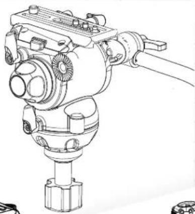
Technical line drawing of a mechanical device with no visible text or symbols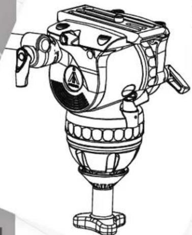
natural_image
Technical line drawing of a mechanical instrument with no visible text or symbols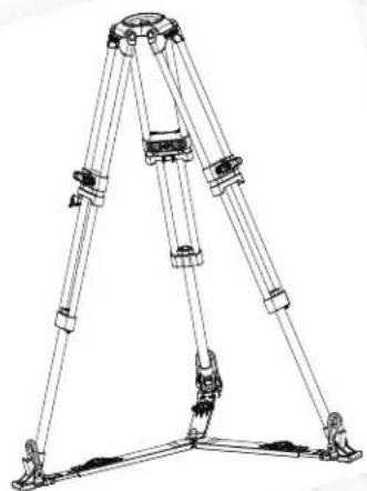
natural_image
Line drawing of a tripod-mounted mechanical device with multiple legs and mounting feet (no text or symbols)All for you
PREFACE
FLUID HEAD

Thank you for purchasing E-IMAGE professional heads and tripods. This manual is an important tool for personnel who operate and maintain this equipment. Inside, you will find detailed information about E-IMAGE tripods and heads, and their proper use. We highly recommend you read the manual carefully and familiarize yourself with each section. There is also a section about safety and maintenance to help you keep your equipment in perfect condition and extend its life.
Please keep this manual for reference while operating and maintaining your equipment.

The E-IMAGE GENTING Series is an upgraded generation of E-Image fluid heads with international influences, innovative designs, and more advanced functions. We refined the counterbalance and drag systems, making balancing faster and simpler. This new series can handle a wider payload range, from 8.8 to 55 pounds, and works with many different styles of camera. Pan handles with rubber grips are included for precise camera movements and are extendable in some models. Each head also has an installed bubble level, and advanced heads have an LED light installed for making adjustments in the dark.
CONTENTS
CONTENTS

Fluid Head Specifications....1
Parts(GH03)....2
Set up & Use 3-5
- Installing the Pan Handle.... 3
2.Removing the Quick Release Plate....3 - Adjusting Tilt Position 4
- Adjusting Pan Position.... 4
5.Drag Adjustment for Pan and Tilt....4
6.Mounting the Camera....5 - Extra functions of the GP1 Quick Release Plate..... 6
Parts(GH06-GH25) 7
Set Up & Use(GH06-GH25) 8-12
- Installing the Pan Handle....8
- Mounting to a Tripod....8
3.Removing the Quick Release Plate....8
4.Mounting a Camcorder....9
5.Mounting a Camera....9-10 - Adjusting the Counterbalance Settings.... 11
- Adjusting the Tilt Drag....11
- Adjusting the Pan Drag....12
9.Changing the Batteries (GH08/08L/10/10L)....13 - Changing the Batteries (GH15,GH25)....14

Tripod Specifications....15-16
Parts(AT7402A) 17
Use AT7402A 18-19
- Releasing and Locking the Legs....18
- Adjusting Tripod Height....18
3.Anti-Slip Rubber Feet....18 - Folding the Tripod for Storage....19
Parts(GA/GC101) 20
Parts(GA/GC102) 21
Parts(GA/GC751 GA/GC752) 22
Use(GA/GC751 GA/GC752 GA/GC101 GA/GC102) ...23-24
- Releasing and Locking the Legs.... 23
- Adjusting the Mid-Level Spreader.... 23
- Adjusting the Ground Spreader....23
4.Removing the Mid-Level Spreader....24 - Installing and Removing a Ground Spreader....24
6.Folding the Tripod for Storage....24
Maintenance....25
Notices & Warnings....26
SPECIFICATIONS
PARTS(GH03)
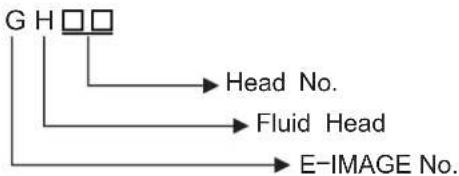
flowchart
graph TD
    A["G H"] --> B["Head No."]
    A --> C["Fluid Head"]
    A --> D["E-IMAGE No."]
| Model No. | Bowl size | Net weight | Load capacity | Grades of drag | Counterbalance | Tilt range | Temperature range |
| GH01 | 65mm | 1.3kg | 5kg | Fixed | Fixed | +80° ~ -65° | -3 0°C~60°C |
| GH03 | 75mm | 1kg | 4kg | Variable (Tilt) | Fixed | +90° ~ -60° | -40°C ~ 80°C |
| GH05 | 75mm | 1.7kg | 3-8kg | Fixed | 0-2 | +90° ~ -45° | -30°C ~ 60°C |
| GH06 | 75mm | 1.6kg | 6kg | 0-50-3 | +90° ~ -60° | -40°C ~ 80°C | |
| GH08 | 75mm | 1.7kg | 8kg | Fixed | 0-6 | +90° ~ -60° | -40°C ~ 80°C |
| GH10 | 75mm | 1.9kg | 10kg | 0-3 | 1-7 | +90° ~ -60° | -40°C ~ 80°C |
| GH10L | 100mm | 2kg | 10kg | 0-3 | 1-7 | +90° ~ -60° | -40°C ~ 80°C |
| GH15 | 100mm | 3.7kg | 15kg | 0-90-5 | +80° ~ -75° | -40°C ~ 80°C | |
| GH20 | 100mm | 3.8kg | 20kg | Fixed | 0-8 | +90° ~ -60° | -30°C ~ 60°C |
| GH25 | 100mm | 4kg | 25kg | 0-7 | 1-15 | +90° ~ -80° | -40°C ~ 80°C |
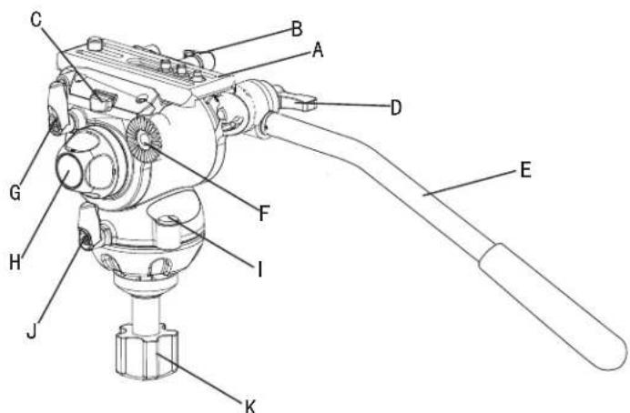
| A | Quick 5 lease 3late |
| B | 4 X/FL5 H/HDVHL3/DIHL/RFMQJ, QRE |
| C | Quick Release Plate Release Button |
| D | Pan Handle Locking Thumb Screw |
| E | Pan Handle |
| F | Pan Handle Mounting Rosette |
| G | Tilt Locking Knob |
| H | Tilt Drag Adjustment Knob |
| I | Bubble level |
| J | Pan locking knob |
| K | BowlLocking Knob |
1
2
SET UP & USE (GH03)
1. Install Pan Handle
Place the pan handle E in the desired position on the pan handle mounting rosette F, then secure it by tightening pan handle locking thumb screw D.

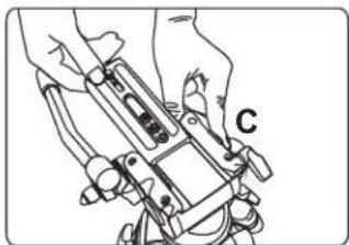
2. Removing the Quick Release Plate
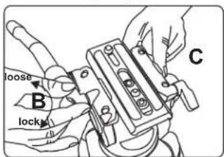
Loosen the quick release plate locking knob B, then press the quick release plate release button C while sliding the plate A towards the back of the head.
natural_image
Line drawing of hands holding a mechanical device with labeled component 'C' (no text or symbols beyond label)3
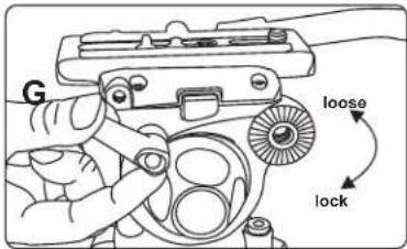
3. Adjusting Tilt Position
Loosen the tilt locking knob G to change tilt position. Tighten the knob to lock the tilt position.
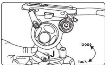
4. Adjusting Pan Position
Loosen the pan locking knob J to change the pan position. Tighten the knob to lock the pan position.
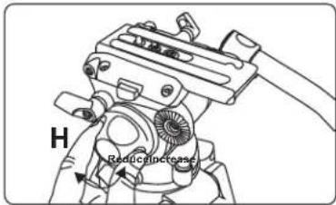
5.Tilt Drag Adjustment
Increase tilt drag by turning the tilt drag adjustment knob H clockwise (as if lightening a screw). Reduce the tilt drag by turning the knob H counter-clockwise (as if loosening a screw).
4
MOUNTING THE CAMERA
EXTRA FUNCTIONS OF GH03,GH06 PLATE
- To mount a camera or camcorder, remove the quick release plate from the tripod head. Attach the plate to the camera using the included 14 "-20 or 3/6"-16 screw. Take care not to over-tighten the screw.
natural_image
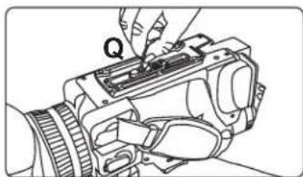
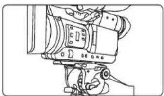
Line drawing of a camera with a hand adjusting the lens (no text or symbols)- With the pan and tilt locked on the head, slide the camera plate onto the head, moving from the back to the front of the head, until the locking button C clicks. Balance the camera by placing the camera's center of gravity as close to the center of the head as possible, then tighten quick release plate lock B.
natural_image
Line drawing of a professional video camera with no visible text or symbols8. Extra Functions of GH03, GH06 plate
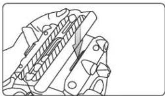
The GH03 and GH06 fluid heads have a special clip that allows the GP1 quick release plate to be pressed down into place. Press one side of the plate against the normal side of the quick release plate track, then press the other side down against the spring clip until the clip clicks, and the plate is secured in place.
natural_image
Technical line drawing of a mechanical component with no visible text or symbols5
6
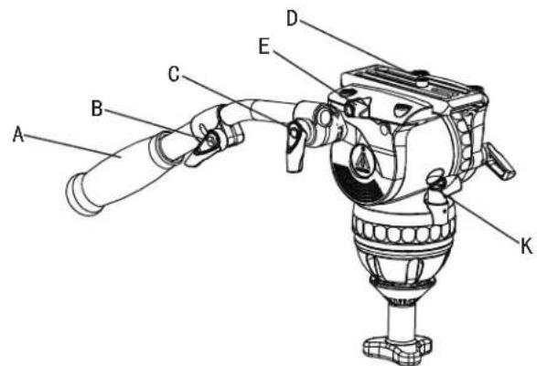
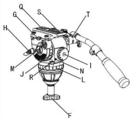
A Pan.Handle....
B ...... Pan Handle Length Adjustment Knob
C....Pan Handle Locking Thumb Screw
D ... Quick Release Plate Camera Locking Screw
E ....Quick Release Plate Locking Knob
F......Bowl Locking Knob
G.....Quick Release Plate Release Button
H....Tilt Locking Knob
1 Counterbalance Adjustment Dial
J Tilt Drag Adjustment Dial
K Pan Locking Knob
L Pan Drag Adjustment Dial
M. Pan Handle Mounting Rosette
N Bubble Level LED Power Button
Q. Quick Release Plate
R Bubble Level
S Rubber Washer
1 Pan Handle Locking Washer
7
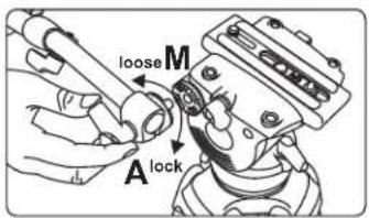
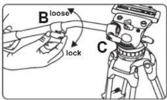
Place the pan handle A in the desired position on the rosette M and tighten the locking thumb screw C, making sure the locking washer T is in place between the handle and rosette. Loosen the length adjustment knob B on the pan handle to adjust the length of the handle. Length adjustment is only available on GB2 and GB3 pan handles.
2. Installing the Fluid Head on a Tripod
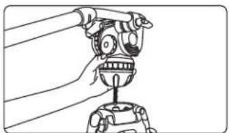
Adjust the tripod to the desired height, and place the ball of the head into the bowl of the tripod. Level the head using the bubble level R, and secure the bowl locking knob F onto the bottom of the head on the underside of the tripod bowl.
natural_image
Line drawing of a robotic arm gripping a mechanical component (no text or symbols)
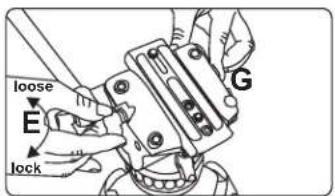
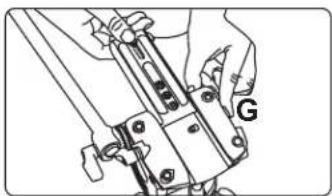
3. Removing the Quick Release Plate
Loosen locking knob E and hold the release button G while sliding the plate toward the rear of the head.
natural_image
Technical line drawing of a mechanical assembly with hands and a labeled component (G), no readable text or symbols present.8
MOUTING THE CAMCORDER VIA ADAPTER
4. Mounting a Large Camera with the PS-C VCT-14 Adapter
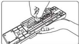
4.1 Attach the quick release plate to the bottom of the VCT-14 mounting adapter (part no. PS-C) using the 14 "-20 or 3/8"-16 screws included with the head. Take care not to over-tighten the screws when mounting the plate.
natural_image
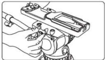
Line drawing of hands using a handheld device to adjust or install a component (no text or symbols visible)4.2 Slide the quick release plate onto the tripod head. The plate release button will click when it is in place.
natural_image
Line drawing of hands holding a firearm (no text or symbols)4.3 Make sure the head's pan and tilt axis are locked, and attach the camera's VCT-14 wedge to the PS-C adapter. It will click when it is locked in place. Loosen the quick release plate lock and adjust the position of the camera to find the desired center of balance.
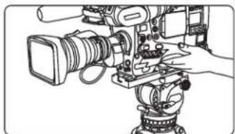
natural_image
Line drawing of a professional video camera with extended screen and tripod (no text or symbols)9
MOUNTING THE CAMERA
5. Mounting the Camera to the Quick Release Plate
5.1 Attach the quick release plate to the bottom of the camera using the included 14 "-20 or 3/8"-16 screws. Take care not to over-tighten the screw when mounting the camera.
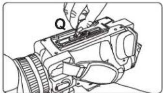
natural_image
Line drawing of a camera with a hand adjusting the lens (no text or symbols)5.2 Make sure the head's pan and tilt axis are locked, then slide the quick release plate onto the head, moving from the rear to the front. The plate release button C will click when the plate is in place. Slide the plate along the track until you find the center of balance, then lock the plate in place with the locking knob E.
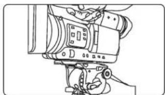
natural_image
Line drawing of a professional video camera with hands operating it (no text or symbols)10
ADJUSTING COUNTERBALANCE & DRAG
ADJUSTING PAN DRAG
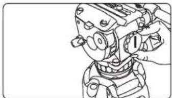
6. Adjusting Counterbalance Settings
Loosen the tilt locking knob H and hold the head steady with the pan handle. Turn the counterbalance dial I to a setting that allows the camera to remain in position without operator assistance. Lower numbers mean less tension; higher numbers use more tension to balance loads.
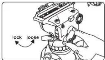
natural_image
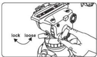
Line drawing of a mechanical assembly with hands adjusting components (no text or symbols)7. Adjusting Tilt Drag
Loosen the tilt locking knob H. Turn the tilt drag adjustment dial J to the desired setting. Lower numbers give less resistance; higher numbers offer more resistance.
natural_image
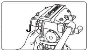
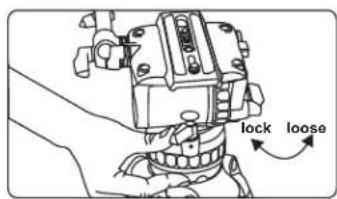
Illustration of a hand operating a mechanical device with no visible text or symbols8. Adjusting Pan Drag
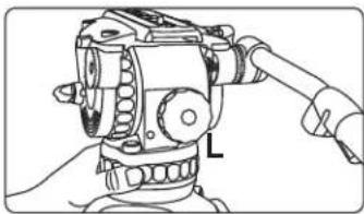
Loosen the pan locking knob K. Use the pan drag adjustment dial L to set the desired amount of pan drag. Lower numbers give less drag; higher numbers offer more resistance.
natural_image
Line drawing of a mechanical device with gears and a lever (no text or symbols)
CHANGE BATTERY OF ILLUMINATED LEVELING BUBBLE (GH08 GH08L GH10 GH10L)
9. Changing the Battery on the Bubble Level LED Light (GH08, GH08L, GH10, GH10L)
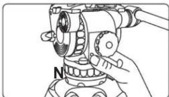
9.1 Test the light by pressing button N to turn it on. If the light turns on, the batteries are still good. The light will turn itself off automatically after 25 seconds.
natural_image
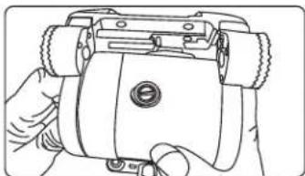
Line drawing of a hand operating a mechanical device with a compass needle (no text or symbols)9.2 To change the batteries, begin by reducing tilt drag and counterbalance to their lowest settings and make sure the tilt axis is unlocked. Tilt the head all the way back to expose the battery compartment, and lock the head in place with the compartment exposed.
natural_image
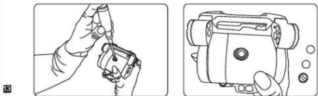
Line drawing of a hand holding a small mechanical device with no visible text or symbols9.3 Remove the battery compartment cover with a flat head screwdriver to access the battery chamber. The GH08, GH08L, GH10, and GH10L heads use 2x LR41 button batteries. Once the batteries are replaced screw on the battery cover and carefully release the tilt lock to return the head to its normal position.
natural_image
Illustration of a hand using a tool to adjust or install a device, showing two views (no text or symbols present)CHANGE BATTERY OF ILLUMINATED LEVELING BUBBLE (GH15 GH25)
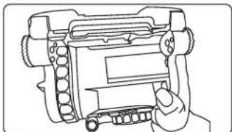
10. Changing Batteries (GH15,GH25)
10.1 Check the battery using the LED activation button N
natural_image
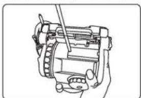
Line drawing of a hand holding a device with gears and buttons (no text or symbols)10.2 If the battery must be changed, reduce tilt drag and counterbalance to their lowest settings and unlock the tilt axis. Tilt the head all the way back to expose the battery chamber, and lock the tilt axis.
natural_image
Technical line drawing of a mechanical assembly with no visible text or symbols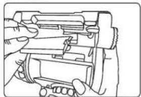
natural_image
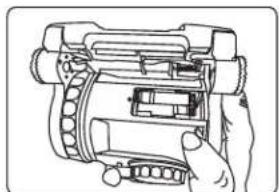
Line drawing of hands operating a mechanical device with no visible text or symbols10.3 Use a Phillips head screwdriver to remove the battery cover. The GH15 and GH25 heads use AAA style batteries. Replace the old batteries with two new ones, and re-install the battery cover. Carefully unlock the tilt axis to restore the head to its normal position.
natural_image
Hand holding a mechanical component with internal gears and shafts (no text or symbols visible)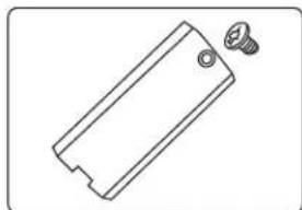
natural_image
Simple line drawing of a rectangular object with a screw and circular hole, no text or symbols present.TRIPODS
SPECIFICATIONS

The E-IMAGE GENTING series is a new generation of E-IMAGE tripods. These tripod legs are all made of high-grade aluminum or carbon fiber materials. The newly designed lock system and patented locking mechanisms provide smooth, quick, and secure locking and unlocking. Equipped with standard 65mm, 75mm, and 100mm bowl systems, E-IMAGE legs will work with any standard video heads. Each tripod can be fitted with mid-level and/or ground spreaders for added stability, or paired with an assortment of dollies for mobility. These tripods are compact when closed, and easy to transport with an assortment of available carrying cases.

flowchart
graph TD
    G["Section"] --> BowlSize["Bowl Size"]
    BowlSize --> Material["Material"]
    E-IMAGENo.[E-IMAGE No.] --> BowlSize
    E-IMAGENo --> Material
| Model No. | Bowl Size | Descrition | Height Range | Transport length | Weight | Payload |
| AT7402B | 65mm | Two stage Aluminum | 650-1510mm | 695mm | 40kg3. | |
| GA751 | 75mm | Single stage Aluminum | 780-1380mm | 820mm | 40kg2. | |
| GC751 | 75mm | Single stage carbon fiber | 780-1380mm | 820mm | 40kg2. | |
| GA752 | 75mm | Two stage Aluminum | 630-1570mm | 720mm | 40kg3. | |
| GC752 | 75mm | Two stage carbon fiber | 630-1570mm | 720mm | 40kg3. | |
| GA101 | 100mm | Single stage Aluminum | 790-1400mm | 845mm | 4.4kg | 60kg |
| GC101 | 100mm | Single stage carbon fiber | 790-1400mm | 845mm | 3.7kg | 60kg |
| GA102 | 100mm | Two stage Aluminum | 470-1600mm | 730mm | 4.9kg | 60kg |
| GC102 | 100mm | Two stage carbon fiber | 470-1600mm | 730mm | 4.4kg | 60kg |
15
PARTS(AT7402B)
USE AT7402B
17
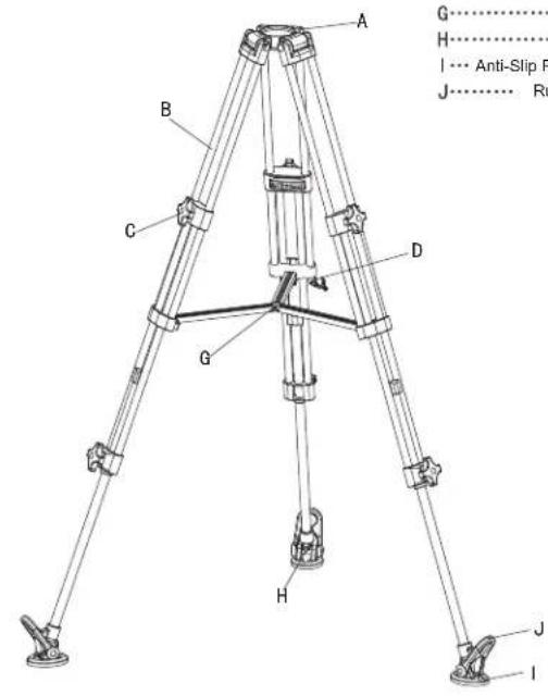
A...... Bowl Base
B Leg Tube
C Locking Knob
D…… Retractable Easy Hook
G Mid-Level spreader
H…… Spiked Tripod Foot
| ... Anti-Slip Rubber Pad (Part no. F3)
J…… Rubber Foot Securing Tab
1. Lock and Unlock Leg Stages
To Loosen: Turn lock C counter-clockwise
To Lock: Turn lock clockwise
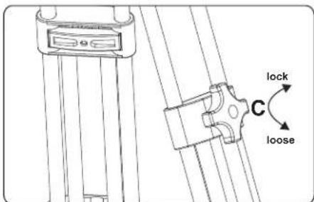
Special Note: It is a best practice to unlock, adjust, and re-lock the tripod legs before the legs are unfolded.
2. Adjusting Tripod Height
Loosen the locking knobs on the leg or legs needing adjustment, set them to the desired height, then re-lock the leg stages.
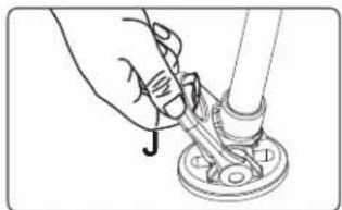
3. Anti-Slip Rubber Feet
To remove the rubber feet, pull the foot-securing tab J up and over the lip of the foot, then lift the foot off of the tab.
natural_image
Hand using a tool to adjust or install a mechanical component (no text or symbols visible)Special Note: The spiked foot is used for shooting outdoors.
18
USE AT7402B
PARTS(GA101/GC101)
4. Folding Tripod
a: Loosen the locking knobs for all extended leg stages and reduce them to their minimum length, then re-lock all of the knobs
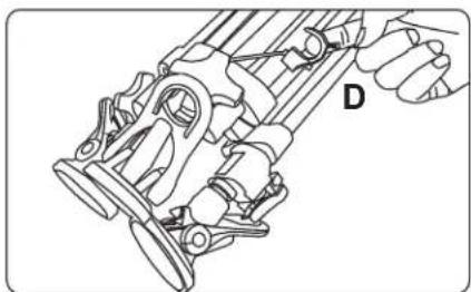
b: Holding the tripod by the bowl, lift up on the center of the mid-level spreader G and fold the legs together. Pull out the retractable easy hook D, wrap it around the legs, and secure the hook to a leg tube to secure the legs.
natural_image
Technical line drawing of a mechanical assembly with labeled component D (no text or symbols beyond label)19
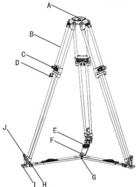
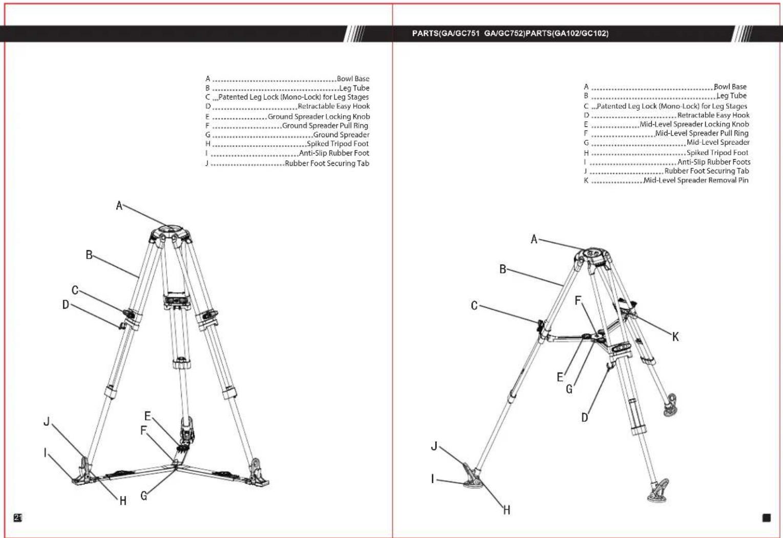
A Bowl Base....
B Leg Tube
C .. Patented Leg Lock (Mono-Lock) for Leg Stages
D Retractable Easy Hook
E Ground Spreader Locking Knob
F Ground Spreader Pull Ring
G Ground Spreader
H Spiked Tripod Foot
1 Anti-Slip Rubber Foot
J ...... Rubber Foot Securing Tab
20
USE(GA/GC751 GA/GC752 GA/GC101 GA/GC102) USE(GA/GC751 GA/GC752 GA/GC101
(A/GC102)
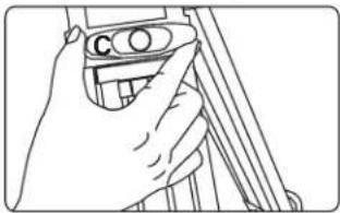
1. Loosening and Locking Tripod Legs
To Loosen: Turn locking knob C counter-clockwise
To Tighten: Turn locking knob C clockwise
natural_image
Line drawing of a hand holding a camera lens, no text or symbols present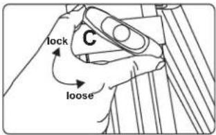
Special Note: It is a best practice to unlock, adjust, and re-lock the tripod legs before the legs are unfolded.
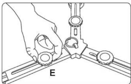
2. Adjusting the Mid-Level Spreader
To make adjustments to the mid-level spreader, loosen the locking knob E and reposition the leg attached to that section of the spreader. When the adjustment is made, tighten the knob to re-secure the spreader.
3. Adjusting the Ground Spreader
To make adjustments to the ground spreader, loosen the locking knob E and reposition the leg attached to that section of the spreader. When the adjustment is made, tighten the knob to re-secure the spreader.
natural_image
Illustration of hands assembling a mechanical component labeled 'E' (no text or symbols on the diagram itself)23
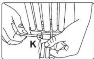
- To remove the mid-level spreader, remove the retaining pin K located where the spreader attaches to the leg.
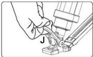
5. Installing a Ground Spreader
To install the ground spreader, remove the rubber tripod feet using the pull-tab J, placed the spiked tripod feet on the ground spreader, and secure them with the rubber tab J on the spreader.
natural_image
Illustration of a hand using a mechanical tool to adjust or install a component (no text or symbols visible)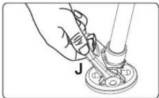
natural_image
Hand using a tool to adjust or install a mechanical component (no text or symbols visible)6. Folding the Tripod
a. Loosen the leg locks and collapse each leg to its minimum length, then lock the knobs.
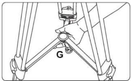
b. Unlock and reduce the all attached spreaders to their minimum size.
c. Securing the tripod by the bowl, pull up on the spreader pull ring F and fold the legs, then pull out the easy hook D and wrap it around the legs, securing the hook to a leg tube.

natural_image
Mechanical assembly diagram showing a lever mechanism with labeled force F (no text or symbols beyond label)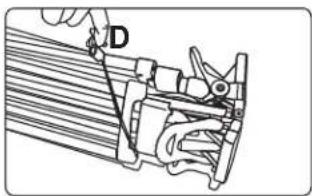
24
Maintenance
Notice & Warning

Daily maintenance:
Storage and Transport:
- When head is not in use, loosen all locks and reduce drag and counterbalance to minimum settings.
- When tripod is not in use, do not store it vertically to avoid it falling and being broken.
- When tripod is not in use or is being transported, keep it safe in the carrying bag.
Inspection of Functions:
- Check the recommended payload and verify locks are functional before mounting anything on a tripod or head to avoid accidental damage.
- To prolong the life of a tripod and head, check and adjust locks, dials, and hardware on a regular basis.
Cleaning & Storage:
- Use a lint-free cloth to clean tripods, heads, and their individual components.
- Keep the tripod and head in a carrying case when they are not in use.
- Use a semi-stiff brush to remove debris and grime that cannot be easily wiped away.
Always engage safety devices like locks and easy hooks when applicable.
Do not use E-IMAGE tripods and fluid heads at temperatures less than -30^ or more than 60^ .
Clean with a mild detergent and soft cloth, a semi-stiff brush, or a vacuum. Check for dust, sand, and other debris in all moving parts. Dry after use in wet conditions.
Important: Products in this manual are not recommended for use in seawater.
If you have any questions during use, consult this manual or contact your local distributor for the fastest service.
In the event that an E-IMAGE product proves defective, contact the nearest authorized E-IMAGE service agent or distributor
- E-IMAGE
- All for you
- CONTENTS
- SPECIFICATIONS
- PARTS(GH03)
- SET UP & USE (GH03)
- Install Pan Handle
- Removing the Quick Release Plate
- Adjusting Tilt Position
- Adjusting Pan Position
- 5.Tilt Drag Adjustment
- MOUNTING THE CAMERA
- EXTRA FUNCTIONS OF GH03,GH06 PLATE
- Extra Functions of GH03, GH06 plate
- Installing the Fluid Head on a Tripod
- Removing the Quick Release Plate
- MOUTING THE CAMCORDER VIA ADAPTER
- Mounting a Large Camera with the PS-C VCT-14 Adapter
- Mounting the Camera to the Quick Release Plate
- ADJUSTING COUNTERBALANCE & DRAG
- ADJUSTING PAN DRAG
- Adjusting Counterbalance Settings
- Adjusting Tilt Drag
- Adjusting Pan Drag
- CHANGE BATTERY OF ILLUMINATED LEVELING BUBBLE (GH08 GH08L GH10 GH10L)
- Changing the Battery on the Bubble Level LED Light (GH08, GH08L, GH10, GH10L)
- CHANGE BATTERY OF ILLUMINATED LEVELING BUBBLE (GH15 GH25)
- Changing Batteries (GH15,GH25)
- PARTS(AT7402B)
- USE AT7402B
- Lock and Unlock Leg Stages
- Adjusting Tripod Height
- Anti-Slip Rubber Feet
- PARTS(GA101/GC101)
- Folding Tripod
- Loosening and Locking Tripod Legs
- Adjusting the Mid-Level Spreader
- Adjusting the Ground Spreader
- Installing a Ground Spreader
- Folding the Tripod
- Maintenance
- Notice & Warning
- Daily maintenance:
- Inspection of Functions:
- Cleaning & Storage:
Brand : E-Image
Model : GH06
Category : Tripod