
M1 - Regulator RGBlink - Free user manual and instructions
Find the device manual for free M1 RGBlink in PDF.


| Product Type | All-in-one Scalable Vision Mixing Processor |
| Brand | RGBlink |
| Model | M1 |
| Input Interfaces | 4x DVI-I (compatible with CVBS, VGA, YPbPr); optional modules for HDMI, SDI, USB, NDI |
| Output Interfaces | 1x HDMI PVW, 1x HDMI PGM; optional SDI and USB 3.0 output modules |
| Supported Resolutions | Up to 1920x1080@60Hz (DVI, HDMI, SDI); multiple VESA and SMPTE standards |
| Audio | Integrated; 24-bit ADC/DAC; SNR 114dB; RCA and 3.5mm connectors; embedded audio support |
| Control | Front panel with LCD touch screen and rotary encoder; RS-232; Ethernet (TCP/IP) |
| Power Supply | AC 85-264V, 50/60Hz; Max 65W |
| Operating Temperature | -25°C to 55°C |
| Storage Humidity | 10% to 90% RH |
| Safety Compliance | FCC Class A; requires protective earth grounding |
| Warranty | 3 years parts and labor |
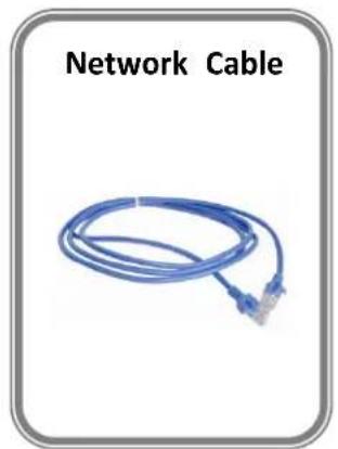
| Accessories Included | AC power cable, HDMI to DVI cable, USB 3.0 cable, network cable, rack ears |
| Optional Modules | NDI input, 3G-SDI input, HDMI input, USB2.0, USB3.0 output, PGM HDMI/SDI/USB output |
| Special Features | NDI | HX2 decoding, USB 3.0 streaming, 20 presets, PTZ control, 13 mask shapes, DSK, blending, transition effects |
| Genlock | BNC input for external sync (supports multiple formats) |
Frequently Asked Questions - M1 RGBlink
User questions about M1 RGBlink
0 question about this device. Answer the ones you know or ask your own.
Ask a new question about this device
Download the instructions for your Regulator in PDF format for free! Find your manual M1 - RGBlink and take your electronic device back in hand. On this page are published all the documents necessary for the use of your device. M1 by RGBlink.
USER MANUAL M1 RGBlink
natural_image
Exterior view of a modern office building (no signage)*Pad not included
User Manual
RGBlink®
Article No: RGB-RD-UM-M1 E003
Revision No: V1.3
CONTENTS
Declarations 3
FCC/Warranty 3
Operators Safety Summary 4
Installation Safety Summary 4
Chapter 1 Your Product....6
1.1 In the Box 6
1.2 Product Overview....7
1.2.1 Front Panel 8
1.2.2 Rear Panel 11
1.2.3 Dimension 13
Chapter 2 Installing Your Product....14
2.1 Plugging in Signals....14
2.2 Plugging in Main Power 14
2.3 Turning on Your Product ....14
Chapter 3 Using Your Product ....15
3.1 Using the MENU Button....15
3.2 Understanding the MENU Structure.... 16
3.3 Using the MENU Button....17
3.3.1 Input Menu 18
3.3.2 Output Menu 20
3.3.3 FREEZE 23
3.3.4 BLACK 23
3.3.5 SCALE 24
3.3.6 Transition Effect 25
3.3.7 DSK 26
3.3.8 BLEND 27
3.3.9 LOGO 28
3.3.10 MASK 29
3.3.11 Audio In .... 30
3.3.12 Audio Out 30
3.3.13 Lock Front Panel 31
3.3.14 Language/语言 31
3.3.15 System 32
3.3.16 PTZ Control....33
3.4 PST Mode 34
3.5 PGM Mode 41
3.6 Switching Mode 41
3.7 Set the Output Parameter 42
3.8 Using Black Out....44
3.9 Saving Views 45
3.10 Recall Saved Settings 46
3.11 USB3.0 Streaming Module 47
3.11.1 USB 3.0 Streaming....47
3.11.2 Streaming Setting 49
Chapter 4 Remote Control Setting ....51
4.1 COM Port Connecting 51
4.2 Network Connecting....52
Chapter 5 Ordering Codes....53
5.1 Product....53
5.2 Options....53
Chapter 6 Contact Us....54
6.1 Contact Us 54
Chapter 7 Appendix ....55
7.1 Specification....55
7.2 Terms & Definitions 60
7.3 Revision History 64
Thank you for choosing our product!
This User Manual is designed to show you how to use this video processor quickly and make use of all the features. Please read all directions and instructions carefully before using this product.
Declarations
FCC/Warranty
Federal Communications Commission (FCC) Statement
This equipment has been tested and found to comply with the limits for a class A digital device, pursuant to Part 15 of the FCC rules. These limits are designed to provide reasonable protection against harmful interference when the equipment is operated in a commercial environment. This equipment generates, uses, and can radiate radio frequency energy and, if not installed and used in accordance with the instruction manual, may cause harmful interference to radio communications. Operation of this equipment in a residential area may cause harmful interference, in which case the user will be responsible for correcting any interference.
Guarantee and Compensation
RGBlink provides a guarantee relating to perfect manufacturing as part of the legally stipulated terms of guarantee. On receipt, the purchaser must immediately inspect all delivered goods for damage incurred during transport, as well as for material and manufacturing faults. RGBlink must be informed immediately in writing of any complains.
The period of guarantee begins on the date of transfer of risks, in the case of special systems and software on the date of commissioning, at latest 30 days after the transfer of risks. In the event of justified notice of compliant, RGBlink can repair the fault or provide a replacement at its own discretion within an appropriate period. If this measure proves to be impossible or unsuccessful, the purchaser can demand a reduction in the purchase price or cancellation of the contract. All other claims, in particular those relating to compensation for direct or indirect damage, and also damage attributed to the operation of software as well as to other service provided by RGBlink, being a component of the system or independent service, will be deemed invalid provided the damage is not proven to be attributed to the absence of properties guaranteed in writing or due to the intent or gross negligence or part of RGBlink.
If the purchaser or a third party carries out modifications or repairs on goods delivered by RGBlink, or if the goods are handled incorrectly, in particular if the systems are commissioned operated incorrectly or if, after the transfer of risks, the goods are subject to influences not agreed upon in the contract, all guarantee claims of the purchaser will be rendered invalid. Not included in the guarantee coverage are system failures which are attributed to programs or special electronic circuitry provided by the purchaser, e.g. interfaces. Normal wear as well as normal maintenance are not subject to the guarantee provided by RGBlink either.
The environmental conditions as well as the servicing and maintenance regulations specified in
this manual must be complied with by the customer.
Operators Safety Summary
The general safety information in this summary is for operating personnel.
Do Not Remove Covers or Panels
There are no user-serviceable parts within the unit. Removal of the top cover will expose dangerous voltages. To avoid personal injury, do not remove the top cover. Do not operate the unit without the cover installed.
Power Source
This product is intended to operate from a power source that will not apply more than 230 volts rms between the supply conductors or between both supply conductor and ground. A protective ground connection by way of grounding conductor in the power cord is essential for safe operation.
Grounding the Product
This product is grounded through the grounding conductor of the power cord. To avoid electrical shock, plug the power cord into a properly wired receptacle before connecting to the product input or output terminals. A protective-ground connection by way of the grounding conductor in the power cord is essential for safe operation.
Use the Proper Power Cord
Use only the power cord and connector specified for your product. Use only a power cord that is in good condition. Refer cord and connector changes to qualified service personnel.
Use the Proper Fuse
To avoid fire hazard, use only the fuse having identical type, voltage rating, and current rating characteristics. Refer fuse replacement to qualified service personnel.
Do Not Operate in Explosive Atmospheres
To avoid explosion, do not operate this product in an explosive atmosphere.
Installation Safety Summary
Safety Precautions
For M1 installation procedures, please observe the following important safety and handling rules
to avoid damage to yourself and the equipment.
To protect users from electric shock, ensure that the chassis connects to earth via the ground
wire provided in the AC power Cord.
The AC Socket-outlet should be installed near the equipment and be easily accessible.
Unpacking and Inspection
Before opening M1 shipping box, inspect it for damage. If you find any damage, notify the shipping carrier immediately for all claims adjustments. As you open the box, compare its contents against the packing slip. If you find any shortages, contact your sales representative. Once you have removed all the components from their packaging and checked that all the listed components are present, visually inspect the system to ensure there was no damage during shipping. If there is damage, notify the shipping carrier immediately for all claims adjustments.
Site Preparation
The environment in which you install your M1 should be clean, properly lit, free from static, and have adequate power, ventilation, and space for all components.
Chapter 1 Your Product
1.1 In the Box
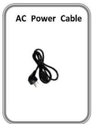
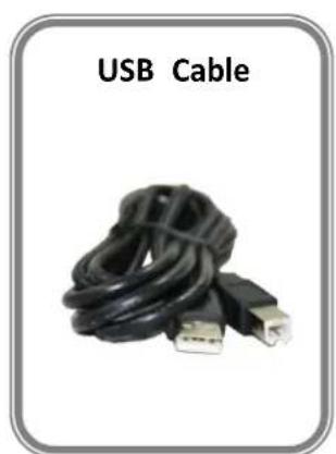
natural_image
Coiled black USB cable with two connectors, labeled 'USB Cable' (no additional text or symbols visible)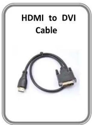
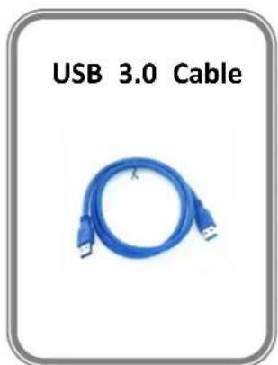
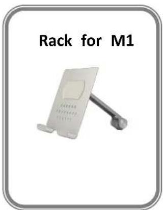
Note:
AC Power Cable supplied as standard according to destination market.
1.2 Product Overview
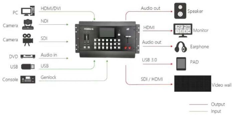
M1 is all-in-one scaling and vision mixing processor.
M1 can up-down cross-covert any input signal to output, which supports 2 layers switching from PVW to PGM. M1 supports Integrated audio. Both LCD touch screen and Menu rotation can be operated. Four input channels are provided in M1. A standard M1 module board with four DVI input signals is fitted. And streaming PGM output via optional USB 3.0 output module is Provided.A wide range of configurable options for users is available.
M1 is also equipped with NDI decoding module, which supports up to 4 Gigabit NDI network ports, which can realize high-quality, low-latency, long-distance transmission applications up to NDI | HX2.
M1 redefines modern hands on scaling and mixing for any environment.
Totally modular and flexible in configuration, M1 is packed with standard features to impress and present with ease.
flowchart
graph LR
    PC["PC"] -->|HDMI/DVI| A["Audio/Video Display"]
    Camera["Camera"] -->|NDI| A
    Camera1["Camera"] -->|SDI| A
    DVD["DVD"] -->|Audio in| A
    USB["USB"] -->|USB| A
    Console["Console"] -->|Genlock| A
    A -->|Audio out| Speaker["Speaker"]
    A -->|Audio out| PST["PST 1 2 3 4 Monitor"]
    A -->|Audio out| Earphone["Earphone"]
    A -->|Audio out| PAD["Pad"]
    A -->|Audio out| VideoWall["Video wall"]
    VideoWall --> Output["Output"]
    VideoWall --> Input["Input"]
1.2.1 Front Panel
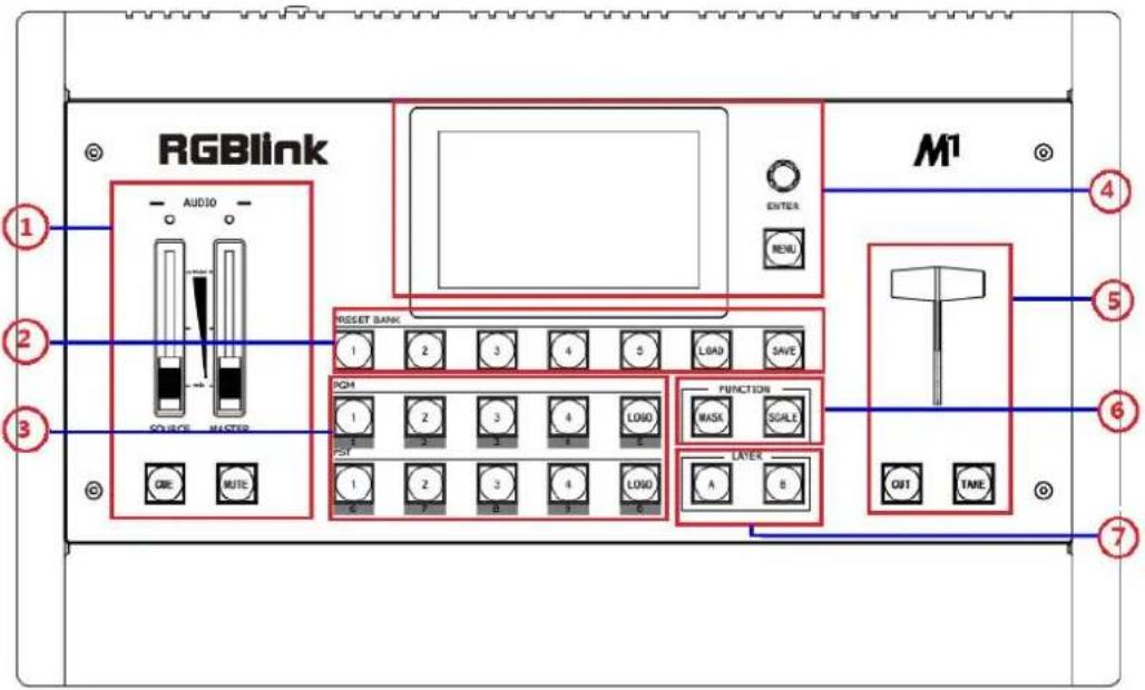
| Panel Instruction | |||
| 1 | Audio adjustment area | 5 | Switching modes area |
| 2 | Presets operation area | 6 | Layer function area |
| 3 | Input sources area | 7 | Layer selection area |
| 4 | Menu and LCD display area | ||
Audio Adjustment Area
| 1 | SOURCE FADERSOURCE FADER adjusts 4 input signals' voice separately to same volume, ranging 0~20.MASTER FADERMASTER FADER is an amplification-factor of all channel, ranging from 0~10; the v of four input signals is the number of multiplying SOURCE by MASTER.CUEThe button of selecting Audio output channel. If the button turns to red color, the current audio output is a layer audio of main output channel. If the button turns green color, the current audio output is a layer audio of preview channel.MUTEMUTE button for audio output, If the button turns to red color, audio is muting the button is white, audio is muting off.Note: Users can use CUE button and MUTE button for zoom in and out of PTZ. |
Presets Operation Area
| 2 | SAVESave all current settings supporting 20 savings.LOADLoad saving views from 1 to 20.PAGEPAGE button is used for save or load, total 5 pages, and 5 banks for each page 1/2/3/4/5 The button is lit when select PAGE or BANK. |
Input Sources Area
| 3 | PGM AreaFor indicating, user can not change the channel or set the size or position in P area. Button turns to red when programming.LOGOEnable or disable the LOGO function. If select “ON”, user can set the X and Y, file from U Disk.1/2/3/4/5/6/7/8/9/0Each button is numbered and can be used as direct number. These buttons turn blue color when used as number key.PST AreaFor indicating, the button turns to yellow color when output the signal in PST of For selecting, push any button to switch the PST signal.For editing, button turns to yellow color -- the channel is used and can be edit button light is off -- the channel is not selected. |
Menu and LCD Display Area
| 4 | MENUMenu and back/exit button.SELECT/ENTERSelection and confirmation button. ENTER button can also be used for controlling rotation angle of PTZ.LCD DisplayThis displays current status of the product, and for feature selections providing interactive choices in conjunction with buttons on the Rear Panel. |
| 5 | CUTZero delay switching. PST can be switched to PGM seamlessly when push this bTAKESeamless switching with transition effects.T-BARWIPE and mix switching. |
Switch Mode Area
Layer Function Area
| 6 | MaskKey the video into special shape including diamond, round, heart, star, triangle a forth.SCALEThis button used for size and crop adjusting. If image quality distorts by improp operation, it can be recover by reset. |
Layer Selection Area
| 7 | A/BThese buttons are used for adding or deleting the layer. The button turns to ye when selecting the layer, green when the layer has been opened, white when d the layer. |
1.2.2 Rear Panel
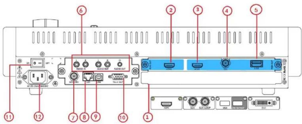
Input Interface
| Input Module | 1 | *Note: Standard with 2 NDI input modules; *With 2 input modules optional.Optional input modules include NDI, DVI, HDMI, USB, SDI.Each DVI module supports 1 DVI-I input and compatible CVBS VGA,YPbPr.Each HDMI module supports 1 HDMI-A input.Each USB module supports 1 USB-B input and 1 USB backup.Each SDI module supports 1 SDI input and 1 SDI loop out.Each NDI module supports 1 RJ45 input. |
Output Interface
| PVW Output | 2 | HDMI output |
| PGM Output | 3 | HDMI output |
| 4 | SDI output (optional, not standard) | |
| 5 | USB3.0 Output(optional,not standard) |
Audio Area
| 6 | Audio In |
| Audio Out | |
| Audio Out( Earphone) |
Control Interface
| 7 | Genlock input BNC port |
| 8 | LAN port RJ-45 |
| 9 | USB port USB-A |
| 10 | TALLY Light |
Power Connection
| 11 | Power Switch |
| 12 | AC: 85-264V Power: Max 65W Power Supply Interface: IEC-3 |
1.2.3 Dimension
Following is the dimension of M1 for your reference:
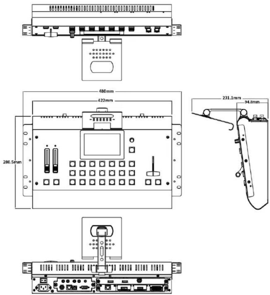
* M1 with optional fitted rack and wings/sides
Chapter 2 Installing Your Product
2.1 Plugging in Signals
Connect signals to the product (ensure all devices are powered off first). Tighten connector screws/locks where provided.
2.2 Plugging in Main Power
Connect IEC cable to device and plug into wall socket. Turn on power at wall socket.
2.3 Turning on Your Product
Turn on the power switch on the rear panel.
OLED display will show as below, completing initialization before loading the latest settings and input/output configuration.
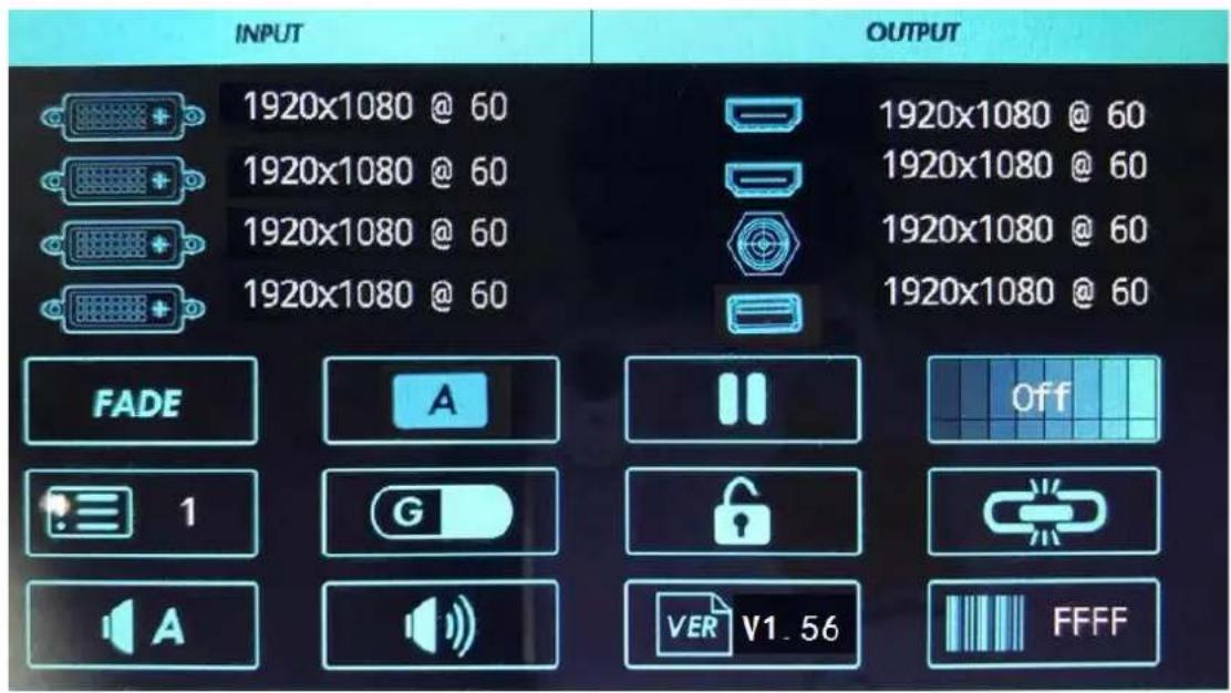
Chapter 3 Using Your Product
3.1 Using the MENU Button
Push the [MENU] button to enter the menu display.
Turn the [ENTER] rotary knob to navigate to the menu item required or touch the icon of LCD screen directly.
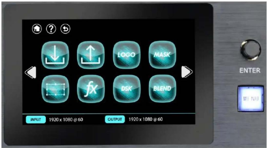
3.2 Understanding the MENU Structure
The MENU structure is shown in the figure below:

flowchart
graph TD
    A["Input"] --> B["Input 1"]
    A --> C["Input 2"]
    A --> D["Input 3"]
    A --> E["Input 4"]
    F["Output"] --> G["Output Format"]
    F --> H["Output Setting"]
    F --> I["External Sync"]
    F --> J["Test Pattern"]
    K["Audio In"] --> L["Audio Input 1"]
    K --> M["Audio Input 2"]
    K --> N["Audio Input 3"]
    K --> O["Audio Input 4"]
    P["Language/语言"] --> Q["English"]
    P --> R["中文"]
    S["System"] --> T["Transition"]
    S --> U["Version"]
    S --> V["Ethernet"]
    S --> W["T-Bar Correction"]
    S --> X["Fader Correction"]
    S --> Y["Key Board Test"]
    S --> Z["Factory Reset"]
    AA["Factory Reset,Save IP"] --> AB["Factory Reset"]
3.3 Using the MENU Button
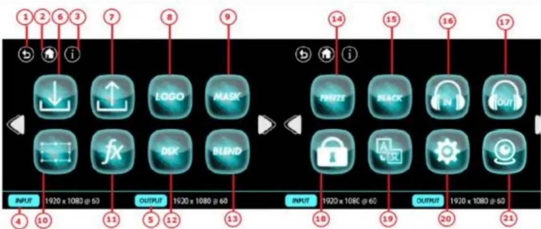
The menu structure is shown on the LCD Screen and in the figure below:
flowchart
graph TD
    A["1"] --> B["2"]
    B --> C["3"]
    C --> D["7"]
    D --> E["8"]
    E --> F["9"]
    F --> G["10"]
    G --> H["4"]
    H --> I["11"]
    I --> J["5"]
    J --> K["12"]
    K --> L["13"]
    L --> M["14"]
    M --> N["15"]
    N --> O["16"]
    O --> P["17"]
    P --> Q["18"]
    Q --> R["19"]
    R --> S["20"]
    S --> T["21"]

    subgraph Left
        U["↓"] --> V["↑"]
        V --> W["LOGO"]
        V --> X["MASK"]
        Y["fX"] --> Z["D&K"]
        Y --> AA["BLEND"]
        AB["OPEN"] --> AC["Freeze"]
        AD["BLACK"] --> AE["IN"]
        AF["Out"] --> AG["Out"]
    end

    subgraph Right
        AH["LOCK"] --> AI["A"]
        AJ["POS"] --> AK["WORD"]
        AL["TIME"] --> AM["SIGHT"]
        AN["TIME"] --> AO["SIGHT"]
        AP["TIME"] --> AQ["SIGHT"]
    end
| LCD Touch Screen Menu Instruction | |||
| 1 | Return Button | 12 | DSK |
| 2 | Homepage | 13 | BLEND |
| 3 | Information Page | 14 | FREEZE |
| 4 | Input Resolution Display | 15 | BLACK |
| 5 | output Resolution Display | 16 | Audio In |
| 6 | Input Menu | 17 | Audio Out |
| 7 | Output Menu | 18 | Lock Front Panel |
| 8 | LOGO | 19 | Language/语言 |
| 9 | MASK | 20 | System |
| 10 | Scale | 21 | PTZ Control |
| 11 | Transition Effect | ||
3.3.1 Input Menu
Push [MENU] button, and enter the menu items. Turn the rotary knob, select [Input Menu]

option in LCD screen, push the knob or touch the
icon directly to confirm, and enter the
menu as follows:
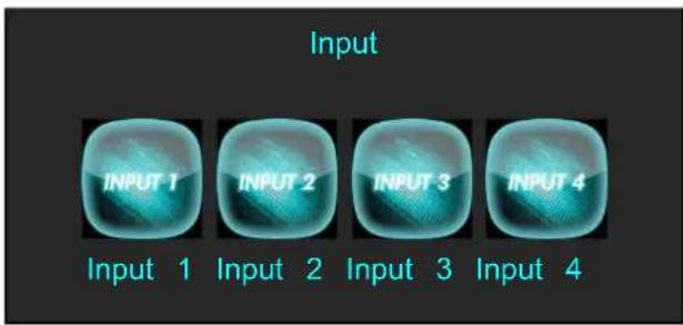
Select any input and enter the menu:
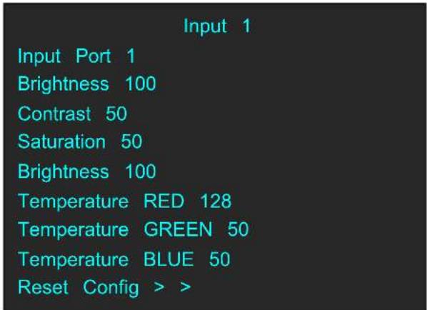
| Input Port | Users can select 0 or 1. |
| Brightness | The adjustment range is from 0 to 100. |
| Contrast | The adjustment range is from 0 to 100. |
| Saturation | The adjustment range is from 0 to 100. |
| Sharpness | The adjustment range is from 0 to 100. |
| Temperature RED | The adjustment range is from 0 to 128. |
| Temperature GREEN | The adjustment range is from 0 to 128. |
| Temperature BLUE | The adjustment range is from 0 to 128. |
| Reset Config | Reset input parameter. |
3.3.1.1 NDI Input Setting
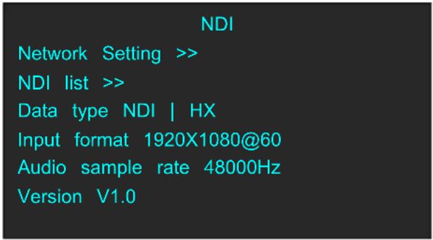
| Network Setting | Touch the knob to enter the network settings menu. |
| NDI list | Show list of NDI resources |
| Data type | NDI | HX |
| Input format | 1920X1080@60 (frame rate optional) |
| Audio sample rate | 48000Hz |
| Version | Show version of module. |
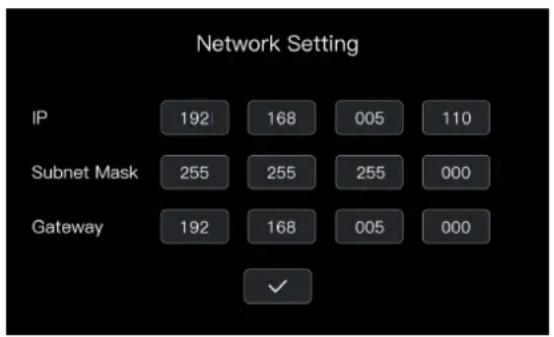
Network settings of NDI input module:
Click network settings to enter network settings of NDI input module
IP: Type in IP address of NDI input module.
Subnet Mask: Type in subnet mask of NDI input module.
Gateway: Type in gateway of NDI input module.
Selection of NDI input signal source:
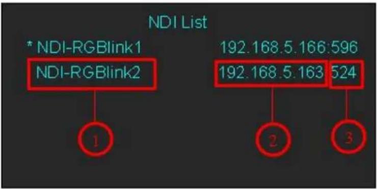
Click the NDI list to enter the interface:
tree
| Node | Value | |---|---| | 1 | NDI-RGBlink1 | | 2 | NDI-RGBlink2 | | 3 | NDI List | | 4 | NDI-RGBlink1 (192.168.5.166:596) | | 5 | NDI-RGBlink2 (192.168.5.163:524) || 1 | Signal source |
| 2 | IP address of signal source |
| 3 | Serial number of signal source |
Note: IP address of NDI signal source and NDI input module need to be in the same network seg
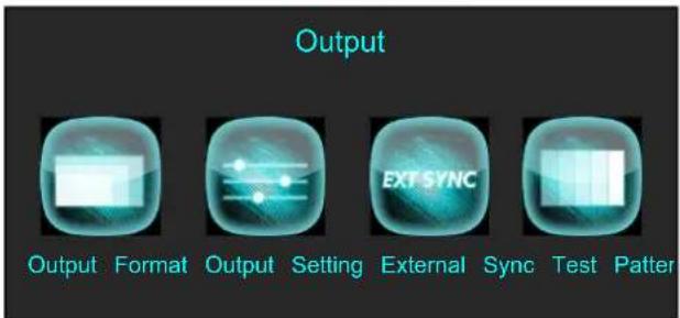
3.3.2 Output Menu
Push [MENU] button, and enter the menu items. Turn the rotary knob, select [Output Menu]
option in LCD screen, push the knob or touch the icon directly to confirm, and enter the
menu as follows:
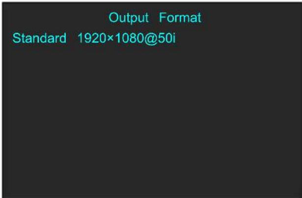
Turn the knob or touch [Output Format] to enter the menu as follows:
Turn the knob or touch [Output Setting] to enter the menu as follows:
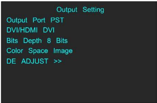
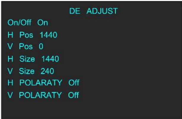
Turn the knob or touch [External Sync] to enter the menu as follows:

Turn the knob or touch [Test Pattern] to enter the menu as follows:
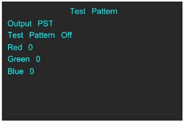
| Output Format | StandardUsers can select standard resolution as actual. |
| Output Setting | Output PortSelect PST OR PGM.DVI/HDMISelect DVI or HDMI.Bit DepthWhen select DVI, the default bit depth is 8 Bits; when se HDMI, the bit depth can be 8 Bits or 10 Bits.Color SpaceSelect Image or Video.DE ADJUSTSelect On or Off to enable or disable DE adjust.Set the horizontal position of output signal.Set the vertical position of output signal.Set the horizontal size of output signal.Set the vertical size of output signal.Enable or disable horizontal polarity.Enable or disable vertical polarity. |
| External Sync | ExternalSelect On or Off to enable or disable external sync.InputShow the input signal.FormatShow the resolution of input signal. |
| Test Pattern | OutputSelect PST or PGM.Test Pattern |
| Select Color Bar, Solid Color or disable the function.RedThe adjustment range is from 0 to 255.GreenThe adjustment range is from 0 to 255.BlueThe adjustment range is from 0 to 255. |
3.3.3 FREEZE
Push [MENU] button, and enter the menu items. Turn the rotary knob, select [FREEZE] option in

LCD screen, push the knob or touch the icon directly to confirm, and enter the menu as follows:
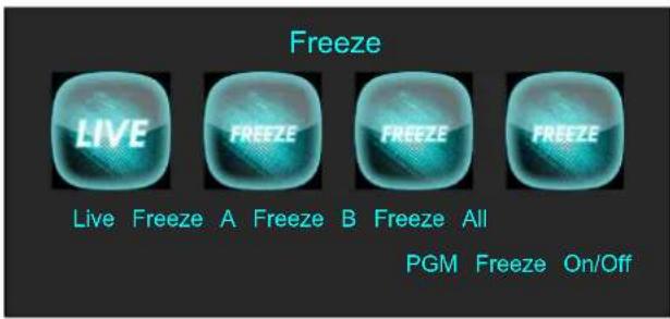
| Live | When freeze the layer, users can select this icon to live. |
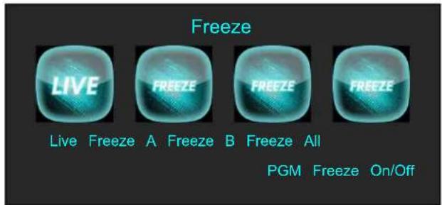
| Freeze A | Freeze layer A. |
| Freeze B | Freeze layer B. |
| Freeze All | Freeze layer A and layer B. |
| PGM Freeze | Select PST Freeze or PGM Freeze. Touch “ON” on LCD scr then PGM Freeze enable; Touch “OFF”, then PST Freeze enable. |
3.3.4 BLACK
Push [MENU] button, and enter the menu items. Turn the rotary knob, select [BLACK] option in

LCD screen, push the knob or touch the icon directly to confirm, and enter the menu as
follows:
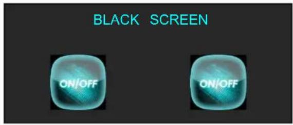
| Off | Select [Off] and push the knob to confirm or touch [Off] disable BLACK function. |
| On | Select [On] and push the knob to confirm or touch [On] t enable BLACK function. |
3.3.5 SCALE
Push [MENU] button, and enter the menu items. Turn the rotary knob, select [SCALE] option in

LCD screen, push the knob or touch the icon directly to confirm, and enter the menu as follows:
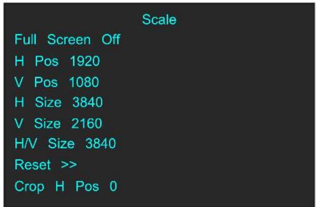
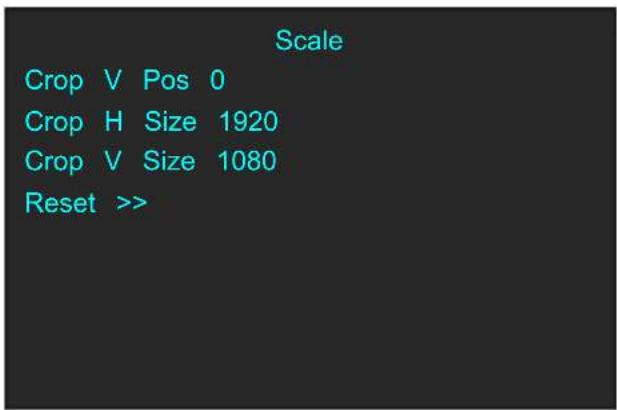
| Full Screen | Select On/Off to enable or disable full screen. |
| H Pos | Set horizontal position. |
| V Pos | Set vertical position. |
| H Size | Set horizontal size. |
| V Size | Set vertical size. |
| H/V Size | the parameter is equal to H Size. |
| Reset | If improper operation occurs, it can be restored by reset. |
| Crop H Pos | Crop the horizontal position. |
| Crop V Pos | Crop the vertical position. |
| Crop H Size | Crop the horizontal size. |
| Crop V Size | Crop the vertical size. |
| Reset | If improper operation occurs, it can be restored by reset. |
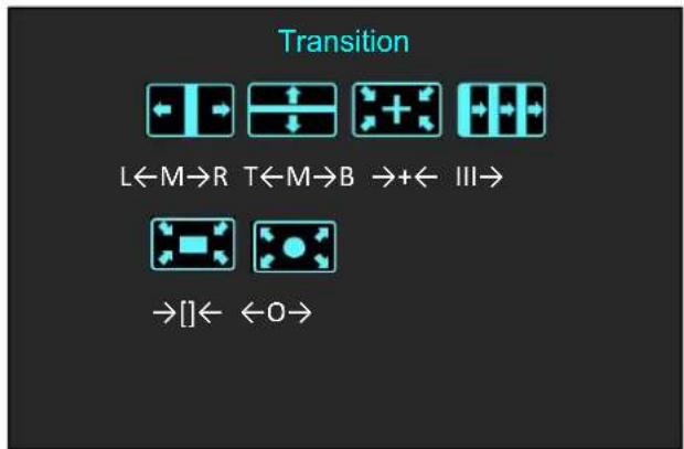
3.3.6 Transition Effect
Push [MENU] button, and enter the menu items. Turn the rotary knob, select [Transition Effect]

option in LCD screen, push the knob or touch the icon directly to confirm, and enter the menu as follows:
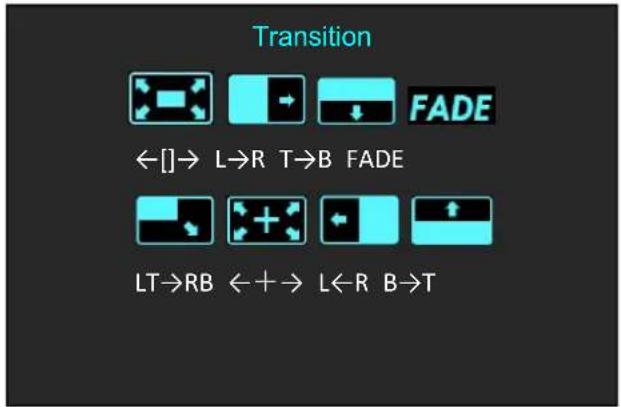
flowchart
graph TD
    A["Transition"] --> B["FADE"]
    B --> C["LT→RB ←+→ L←R B→T"]
    C --> D["Left→L→R T→B FADE"]
flowchart
graph TD
    A["L"] --> B["←I→"]
    C["T"] --> D["←M→R"]
    E["B"] --> F["←M→B"]
    G["III"] --> H["→+←"]
    I["IV"] --> J["→+←"]
    K["VI"] --> L["→+←"]
    M["VI"] --> N["→+←"]
    O["VI"] --> P["→+←"]
    Q["VI"] --> R["→+←"]
    S["VI"] --> T["→+←"]
    U["VI"] --> V["→+←"]
    W["VI"] --> X["→+←"]
    Y["VI"] --> Z["→+←"]
    AA["VI"] --> AB["→+←"]
    AC["VI"] --> AD["→+←"]
    AE["VI"] --> AF["→+←"]
    AG["VI"] --> AH["→+←"]
    AI["VI"] --> AJ["→+←"]
    AK["VI"] --> AL["→+←"]
    AM["VI"] --> AN["→+←"]
    AO["VI"] --> AP["→+←"]
    AQ["VI"] --> AR["→+←"]
    AS["VI"] --> AT["→+←"]
    AU["VI"] --> AV["→+←"]
    AW["VI"] --> AX["→+←"]
    AY["II"] --> AZ["←I→"]
    BA["II"] --> BB["←M→R"]
    BC["II"] --> BD["T←M→B"]
    BE["II"] --> BF["→+←"]
    BG["II"] --> BH["III→"]
    BI["II"] --> BJ["→+←"]
    BK["II"] --> BL["→+←"]
    BM["II"] --> BN["→+←"]
    BO["II"] --> BP["→+←"]
    BQ["II"] --> BR["→+←"]
    BS["II"] --> BT["→+←"]
    BU["II"] --> BV["→+←"]
    BW["II"] --> BX["→+←"]
    BY["II"] --> BZ["→+←"]
 | ←[]→ | Iris Box |
 | L→R | Wipe to Right |
 | T→B | Wipe to Bottom |
 | FADE | Fade In and Fade Out |
 | LT→RB | Wipe to Bottom Right |
 | ←+→ | Iris Cross |
 | L←R | Wipe to Left |
 | B→T | Wipe to Top |
 | L←M→R | Center Split Horizontal |
 | T←M→B | Center Split Vertical |
 | →+← | Cross Inwards |
 | III→ | Blinds Vertical |
 | →[]← | Box Inwards |
 | ←O→ | Iris Round |
3.3.7 DSK
Push [MENU] button, and enter the menu items. Turn the rotary knob, select [DSK] (DSK function
only acts on Layer B) option in LCD screen, push the knob or touch the icon directly to confirm, and enter the menu as follows:
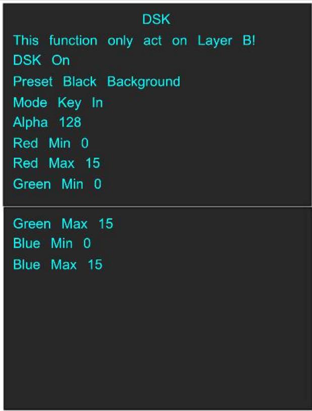
| DSK | Select On/Off to enable or disable DSK. |
| Preset | Select background color from black, white, red, green, blue or “user” to . |
| Mode | Key In or Key Out can be selected. |
| Alpha | Set the Alpha parameter. The adjustment range is from 0 128. |
| Red Min | The adjustment range is from 0 to 255. |
| Red Max | The adjustment range is from 0 to 255. |
| Green Min | The adjustment range is from 0 to 255. |
| Green Max | The adjustment range is from 0 to 255. |
| Blue Min | The adjustment range is from 0 to 255. |
| Blue MAX | The adjustment range is from 0 to 255. |
3.3.8 BLEND
Push [MENU] button, and enter the menu items. Turn the rotary knob, select [BLEND] (BLEND
function only acts on Layer B) option in LCD screen, push the knob or touch the iron directly to confirm, and enter the menu as follows:
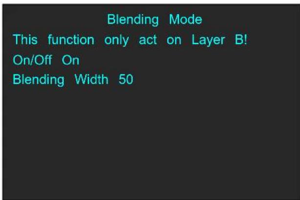
| On/Off | Select On/Off to enable or disable blending mode. |
| Blending Width | Users can adjust blending width ranging from 0 to 90. |
3.3.9 LOGO
Push [MENU] button, and enter the menu items. Turn the rotary knob, select [LOGO] option in

LCD screen, push the knob or touch the icon directly to confirm, and enter the menu as follows:
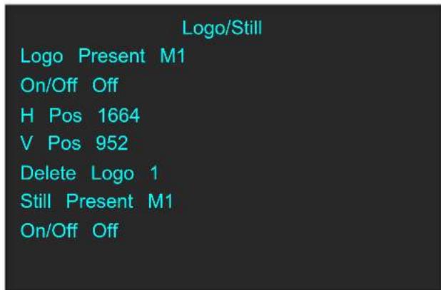
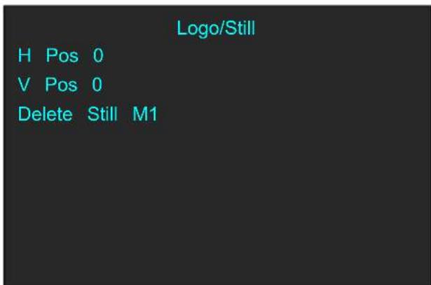
| Logo Present | Select the present logo. |
| On/Off | Select On/Off to enable or disable Logo. |
| H Pos | Set the horizontal position of logo. |
| V Pos | Set the vertical position of logo. |
| Delete Logo | Users can select any saved logo to delete. |
| Still Present | Select the present still. |
| On/Off | Select On/Off to enable or disable Still. |
| H Pos | Set the horizontal position of still. |
| V Pos | Set the vertical position of still. |
| Delete Still | Users can select any saved still to delete. |
3.3.10 MASK
Push [MENU] button, and enter the menu items. Turn the rotary knob, select [MASK] option in

LCD screen, push the knob or touch the icon directly to confirm, and enter the menu as follows:
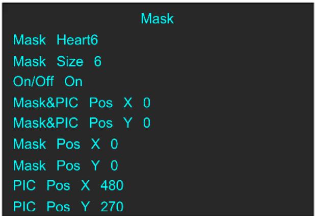
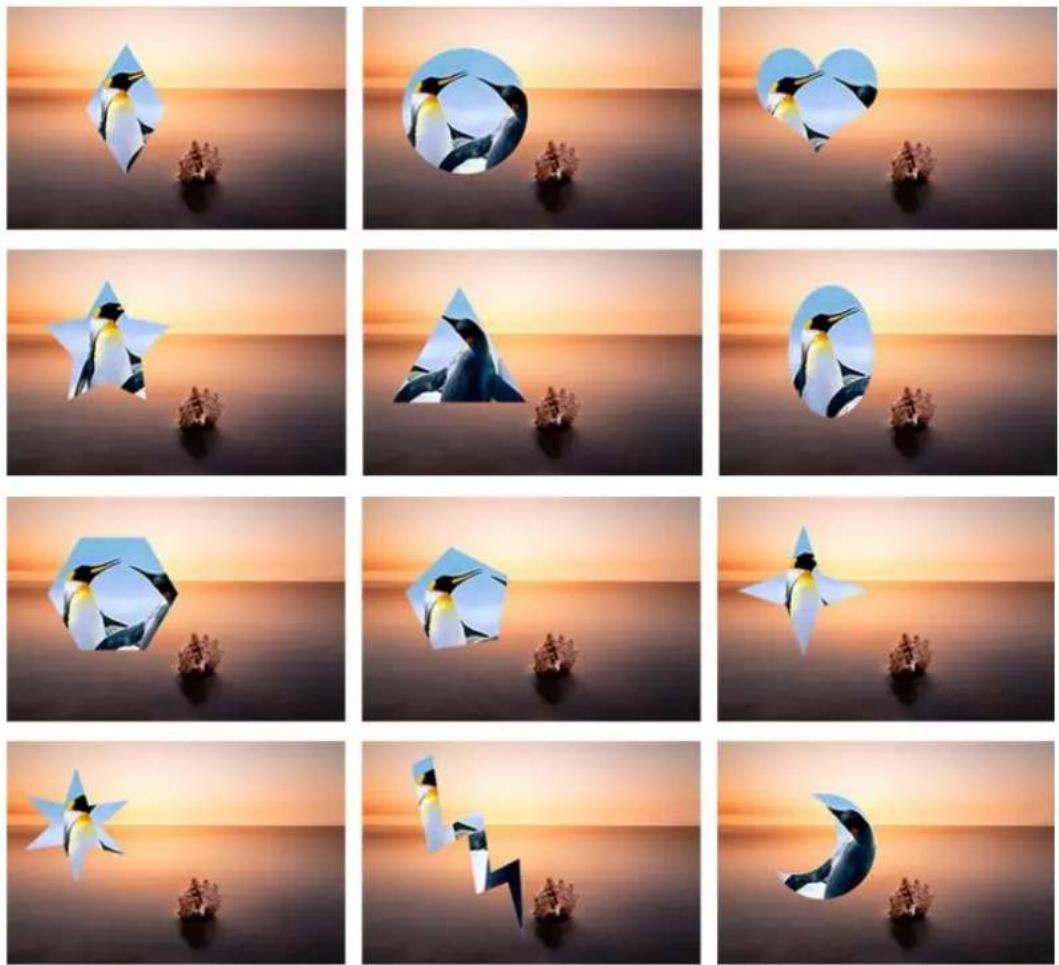
| Mask | 13 kinds of mode: diamond, round, heart, star, triangular, hexagons, pentagon, 4 point star, 6 point star, lighting, crescent left and crescent right. |
| Mask Size | Set the mask size. |
| On/Off | Select On/Off to enable or disable mask. |
| Mask&PIC Pos X | Set the horizontal position of mask and picture. |
| Mask&PIC Pos Y | Set the vertical position of mask and picture. |
| Mask Pos X | Set the horizontal position of mask. |
| Mask Pos Y | Set the vertical position of mask. |
| PIC Pos X | Set the horizontal position of picture. |
| PIC Pos Y | Set the vertical position of picture. |
3.3.11 Audio In
Push [MENU] button, and enter the menu items. Turn the rotary knob, select [Audio In] option in

LCD screen, push the knob or touch the icon directly to confirm, and enter the menu as follows:
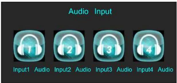
Select a input audio from Input1 Audio to Input4 Audio, and enter the menu as follows:
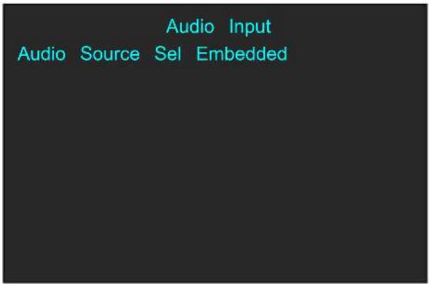
| Audio Source Sel | The Audio Source Selection is embedded or External. |
3.3.12 Audio Out
Push [MENU] button, and enter the menu items. Turn the rotary knob, select [Audio Out] option

in LCD screen, push the knob or touch the icon directly to confirm, and enter the menu as follows:
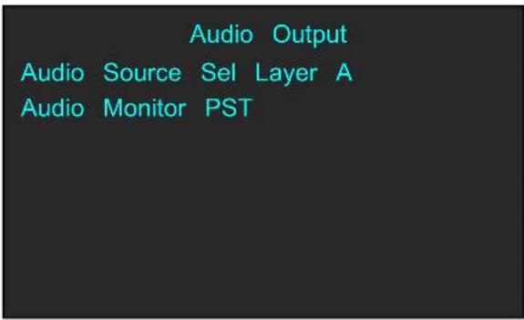
| Audio Source Sel | Users can select Layer A or Layer B as audio source. |
| Audio Monitor | Users can select PST or PGM as andio monitor. |
3.3.13 Lock Front Panel
Push [MENU] button, and enter the menu items. Turn the rotary knob, select [Lock Front Panel]
option in LCD screen, push the knob or touch the icon directly to confirm, and enter the menu as follows:
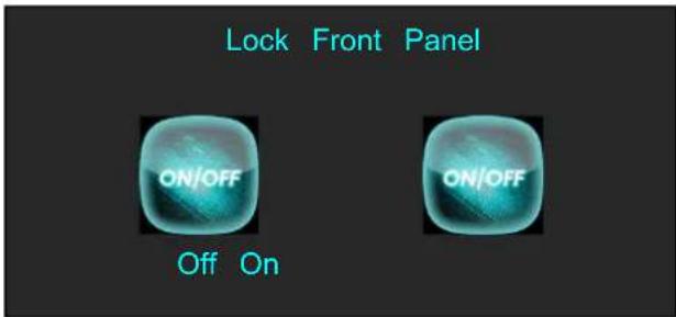
| Off | Select [Off] and push the knob to confirm or touch [Off] to revive the Front |
| On | Select [On] and push the knob to confirm or touch [On] to lock the Front Pa |
3.3.14 Language/语言
Push [MENU] button, and enter the menu items. Turn the rotary knob, select [Language/语言]
option in LCD screen, push the knob or touch the icon directly to confirm, and enter the menu as follows:
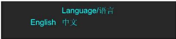
English Select [English] and push the knob to confirm or touch [English] to choose E
中文 Select [中文] and push the knob to confirm or touch [中文] to choose Chinese.
3.3.15 System
Push [MENU] button, and enter the menu items. Turn the rotary knob, select [System] option in

LCD screen, push the knob or touch the iron directly to confirm, and enter the menu as follows:
System
Transition Version Ethernet T-Bar Correction
Fader Correction Kev Board
| Transition | Trans TimeThe adjustment range is from 1.0S to 9.9S. |
| Version | Show the version of COM MCU, EXT MB MCU, PGM MCU, PGM Core, KEY MCU. |
| Ethernet | DHCPEnable or disable the network function. If select [ON], user can the IP address, subnet mask and gateway.StateShow the present state of DHCP, IP, Subnet Mask, Gateway. |
| T-Bar Correction | Step 1: Press the T-BAR to the topStep 2: Choose On or OffStep 3: Press the T-BAR to the bottomStep 4: Choose On or OffT-Bar Calibration::0~1024 |
| Fader Correction | Step 1: Push Fader 1&2 to topStep 2: Choose On or OffStep 3:Push Fader 1&2 to the bottomStep 4: Choose On or OffFader Calibration: 0:0 |
| Key Board | MASKUsers can custom Self, Black or FS.PGM LOGOUsers can custom Self or PGM Freeze.PST LOGOUsers can custom Self or PST Freeze. |
3.3.16 PTZ Control
Click the camera ico

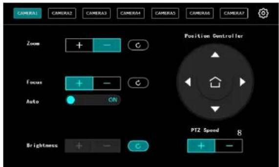
Click the Settings menu enter the interface of M1 Camera IP Settings.
Turn on the IP setting switch: "valid" is ON,
Old IP address: Input the current IP address of the camera.
New IP address: Input the actual new IP address according to the actual demand.
Note: M1 IP address and PTZ camera need to be in a network segment.
Set the camera IP address and 📄 after successful setting, the M1 interface will prompt "Camera setting is successful".
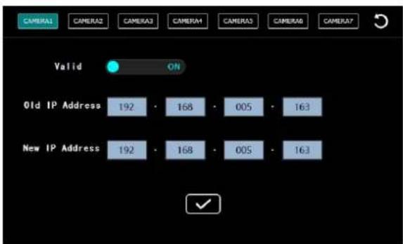
Note: IP Settings can only be modified on M1 using the PTZ camera specified by RG
Set camera parameters such as zoom, focus, position adjustment, preset save, screen brightness adjustment and speed adjustment.
Zoom: Click [+] on the touch panel to zoom in the partial picture of the camera, and click [-] to zoom out
Focus: The system defaults to auto focus. If manual focus is needed, the auto focus function can be turned off
Brightness: Adjust the brightness of the camera
PTZ Speed: Controls the direction key induction speed of the position controller. The range is 1-13
Position controller: Click up, down, left and right to adjust the camera view Angle.
3.4 PST Mode
M1 supports 1 HDMI preview output, and it supports the functions as below:
3.4.1 Signal Selection
Push any button in Input Sources Area, for example, push the button [3], the border of signal 3 will turn to yellow, and the signal in PGM monitor will turn to signal 3.
3.4.2 Add or Delete Layer
Push any button of [A] to [B] in Layer Selection Area to add or delete the layer.
Add layer: The light is lit.
Select layer: The light is flashing.
Delete layer: The light is off.
3.4.3 Freeze the Layer
Push the [FREEZE] button in LCD screen, Select as needed to freeze layer A, layer B or 2 layers, push the button
3.4.4 2 Layers Presets
(1) Push A or B button in Layer selection Area to select 1 or 2 layouts, including 1P, PIP.
(2) User can adjust the position, size for the selected layer, and set DSK, BLEND and MASK, some function coming soon.
3.4.5 Scale and Crop the Layer
(1) Push any button of [A] to [B] in Layer Selection Area, the light is red lit when the layer is selected.

(2) Push the [SCALE] button in Layer Adjustment Area of on the LCD screen, and enter the scale menu as follows:
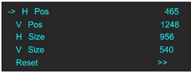
Use the rotary knob to adjust the scale of the layer.
H Pos: Set horizontal position.
V Pos: Set vertical position.
H Size: Set horizontal size.
V Size: Set vertical size.
Reset: If improper operation occurs, it can be restored by reset

(3) Push the [SCALE] button in Layer Adjustment Area on the LCD screen, and enter the scale menu as follows:
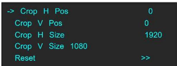
Use the rotary knob to adjust the crop of the layer.
Crop H Pos: Crop the horizontal position.
Crop V Pos: Crop the vertical position.
Crop H Size: Crop the horizontal size.
Crop V Size: Crop the vertical size.
Reset: Reset crop if image quality i distorted by improper operation.
3.4.6 DSK Setting
(1) Firstly, enable the 2 layers function.
(2) Push [MENU] button, and enter to the menu items. Turn the rotary knob, and select
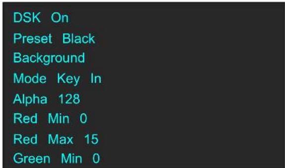
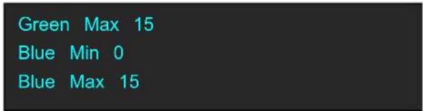
DSK: Can select enable or disable the DSK function.
Preset: Users can select black background, white background, red background, green background and blue background.
Mode: Select Key In or Key Out.
Alpha: The adjustment range is between 0\~128.
Red Min: The adjustment range is between 0\~255.
Red max: The adjustment range is between 0\~255.
Green Min: The adjustment range is between 0\~255.
Green Max: The adjustment range is between 0\~255.
Blue Min: The adjustment range is between 0\~255.
Blue Max: The adjustment range is between 0\~255.
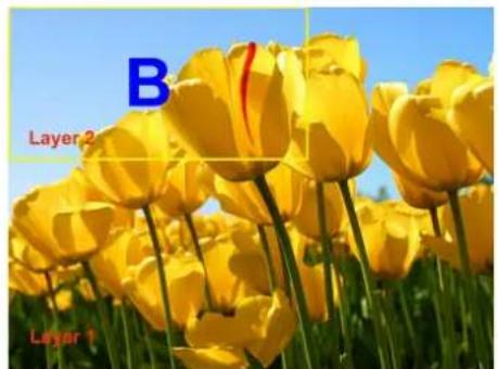
3.4.6.1 Key In and Key Out
(1) Key In
To cut out the color selected in [Preset] and other colors remain unchanged. Take Black Background and Blue Background for example, see the effect below:


(2) Key Out
The color selected in [Preset] remains unchanged and other colors are cut out. Take Black Background and Blue Background for example, see the effect below:

3.4.7 Transitions Setting
(1) Touch the transition buttons in LCD screen, M1 supports 14 kinds of wipe modes:
Touch the transition button, your can select []
Touch the transition button, can select L→R.
Touch the transition button, user can select T→B.
Touch the transition button, FADE select fade.
Touch the transition button, user can select LT→RB.
Touch the transition button, user can select + .
Touch the transition button, user can select L←R.
Touch the transition button, user can select B→T.
Touch the transition button, user can select L←M→R.
Touch the transition button, user can select T←M→B.
Touch the transition button, user can select →+←.
Touch the transition button, user can select III→.
Touch the transition button, user can select →[]←.
Touch the transition button, user can select O .
(2) Push the [TAKE] button, or use T-bar switcher to switch the image to program with selected wipe.
3.4.8 Audio In Setting
(1) Push [MENU] button, and enter the menu items. Turn the rotary knob, select
option in LCD screen, rotary the knob or touch the directly to confirm.
(2) Select the Audio input 1-4 for setting:
Audio Source Sel Embedded
Audio Gain 0
Audio Delay 0 ms
Audio Source Sel: The default is Embedded.
Audio Gain: The adjustment range is between 0\~100
Audio Delay: The adjustment range is between 0\~20ms
3.4.9 Audio Out Setting
(1) Push [MENU] button, and enter the menu items. Turn the rotary knob, select

option in LCD screen, rotary the knob or touch the icon directly to confirm.
(2) Select the Audio Output for setting:
Audio Source Sel Layer A
Audio Gain 0
Monitor Select 0
Mute On
Audio Source Sel: Select Layer A or Layer B
Audio Gain: The adjustment range is between 0\~100
Monitor Select: Select PST or PGM
Mute: Select On or Off
3.4.10 BLEND Setting
Push [MENU] button, and enter the menu items. Turn the rotary knob, select

LCD screen, rotary the knob or touch the icon directly to confirm.
Layer Select
Layer A
Blending Mode
3D Frame
Blending Width 0
On/off
On
Layer Select: Select Layer A or Layer B
Blending Mode: Including 3D Frame, Pure Color Frame, Outside, Inline 4 modes
Blending Width: The adjustment range is between 1\~90
On/Off: Select On or Off
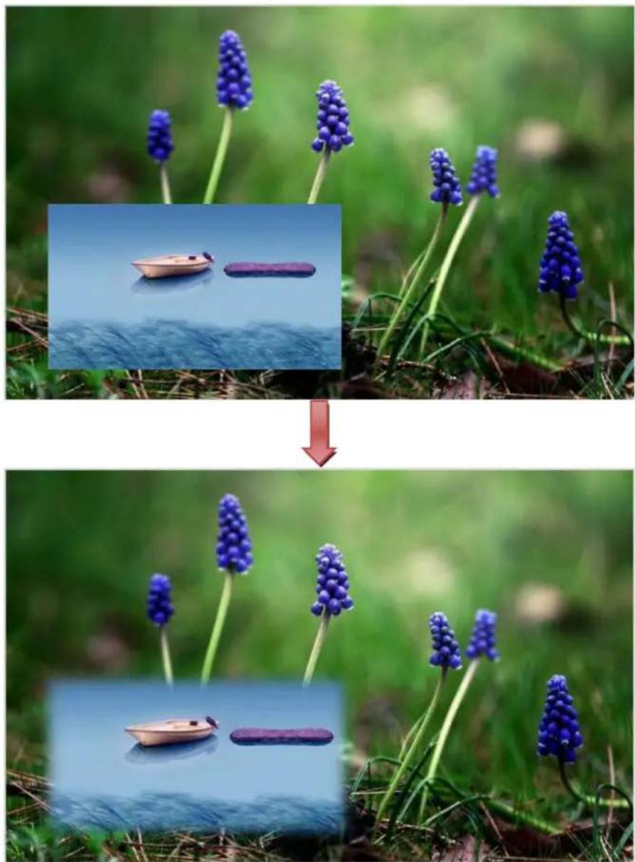
For example, set the Blending Width as 50, see the effect below:
natural_image
Two-panel image showing a blue water droplet on green grass, with a small boat floating nearby; no text or symbols present.3.4.11 Mask Setting
(1) Push [MENU] button, and enter the menu items. Turn the rotary knob, select

on LCD screen, rotary the knob or touch the directly to confirm.
Mask Mask Mask Layer Mask & PIC POS
(2) Select the Mask for setting :
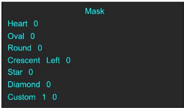
Customs: Coming soon
Turn the rotary knob, and select
User can also Press the layer mask selection button in Layer Mask Area to select a mask. The 13 masks are as follows:
natural_image
Grid of 12 panels showing penguin silhouettes floating on a beach at sunset, with no visible text or symbols.
natural_image
Sunset scene with a crescent moon and a small boat on calm water (no text or symbols)3.5 PGM Mode
- Switch the edited PST image to program by pushing the [CUT], [TAKE] button or T-bar, and then the PGM image will return to PST state, which can be edited.
- There are 1 HDMI output and 1SDI output for program, and up to support 1920x1080 output resolution.
3.6 Switching Mode
- T-BAR switch: Switch the PST image to program with wipe and fade by T-bar.
- CUT switch: Seamless switch the PST image to program by pushing [CUT] button.
- TAKE switch: Switch the PST image to program with wipe and fade by pushing [TAKE] button.
- CUE switch: EARNPHONE voice via CUE transfer PST to PGM.
- MUTE switch: MUTE only for PGM voice.
3.7 Set the Output Parameter
Select the Output Resolution
Push the [MENU] button, and enter the menu items, turn the rotary knob and select

Push the rotary knob to confirm, and enter to the menus as below:
Output Format
Output Setting
External Sync
Test Pattern
- CONTENTS
- Declarations 3
- Chapter 1 Your Product....6
- Chapter 2 Installing Your Product....14
- Chapter 3 Using Your Product ....15
- Declarations
- FCC/Warranty
- Federal Communications Commission (FCC) Statement
- Guarantee and Compensation
- Operators Safety Summary
- Do Not Remove Covers or Panels
- Power Source
- Grounding the Product
- Use the Proper Power Cord
- Use the Proper Fuse
- Do Not Operate in Explosive Atmospheres
- Installation Safety Summary
- Safety Precautions
- Unpacking and Inspection
- Site Preparation
- Chapter 1 Your Product
- In the Box
- Note:
- Product Overview
- Front Panel
- Audio Adjustment Area
- Rear Panel
- Input Interface
- Output Interface
- Audio Area
- Control Interface
- Dimension
- Chapter 2 Installing Your Product
- Plugging in Signals
- Plugging in Main Power
- Turning on Your Product
- Chapter 3 Using Your Product
- Using the MENU Button
- Understanding the MENU Structure
- Using the MENU Button
- Input Menu
- NDI Input Setting
- Output Menu
- FREEZE
- BLACK
- SCALE
- Transition Effect
- DSK
- BLEND
- LOGO
- MASK
- Audio In
- Audio Out
- Lock Front Panel
- Language/语言
- System
- System
- PTZ Control
- PST Mode
- Signal Selection
- Add or Delete Layer
- Freeze the Layer
- 2 Layers Presets
- Scale and Crop the Layer
- DSK Setting
- Key In and Key Out
- Key In
- Key Out
- Transitions Setting
- Audio In Setting
- Audio Out Setting
- BLEND Setting
- Mask Setting
- Customs: Coming soon
- PGM Mode
- Switching Mode
- Set the Output Parameter
- Select the Output Resolution
- Customs Output Resolution
- Output Setting
- External Sync
- Using Black Out
- Saving Views
- Recall Saved Settings
- USB3.0 Streaming Module
- USB 3.0 Streaming
- OBS Setting
- Audio Setting
- Streaming Setting
- Chapter 4 Remote Control Setting
- COM Port Connecting
- Network Connecting
- Chapter 5 Ordering Codes
- Product
- Options
- Chapter 6 Contact Us
- Contact Us
- RGBlink
- Headquarters
- China Regional
- Sales & Support
- Beijing Region
- Office
- Europe Regional
- Chapter 7 Appendix
- Specification
- Terms & Definitions
- Revision History
Brand : RGBlink
Model : M1
Category : Regulator