
FC-50 - Audio/video extender Kramer - Free user manual and instructions
Find the device manual for free FC-50 Kramer in PDF.


| Product Type | RS-232 Range Extender |
| Brand | Kramer |
| Model | FC-50 |
| Dimensions (W x D x H) | 5.32 cm x 7.25 cm x 4.2 cm (2.09" x 2.85" x 1.65") |
| Weight | Approx. 0.3 kg (0.67 lbs) |
| Power Supply | 12V DC, 42 mA (power adapter included) |
| Maximum Baud Rate | Up to 115.2 kbaud |
| Maximum Range | Up to 1000 m (3300 ft) over CAT5 cable |
| Interface | RS-232 on 9-pin D-sub connector, 1 CAT5 RJ-45 connector |
| LED Indicator | Green (PC mode) / Red (Device mode) |
| Operation Mode | Bidirectional RS-232 with selectable crossed/straight connection |
| Power Connect Feature | Supports power over STP cable up to 50m; separate power for longer distances |
| PC/Device Button | Press for device connection, release for PC connection |
| Cable Recommendation | Use Shielded Twisted Pair (STP) for best performance and EMI compliance |
| Warranty | 7 years limited warranty on labor and parts |
| Compliance | FCC and CE approved (with STP cable) |
| Maintenance | No user-serviceable parts; keep away from moisture, dust, and extreme temperatures |
| Safety | Use only provided power supply; disconnect power before servicing |
| Spare Parts & Repairability | Contact authorized Kramer dealer for service; do not attempt internal repairs |
Frequently Asked Questions - FC-50 Kramer
User questions about FC-50 Kramer
0 question about this device. Answer the ones you know or ask your own.
Ask a new question about this device
Download the instructions for your Audio/video extender in PDF format for free! Find your manual FC-50 - Kramer and take your electronic device back in hand. On this page are published all the documents necessary for the use of your device. FC-50 by Kramer.
USER MANUAL FC-50 Kramer
Kramer Electronics, Ltd.

USER MANUAL
Model:
FC-50
RS-232 Range Extender
Contents
1 Introduction 1
2 Getting Started 1
2.1 Quick Start 2
3 Overview 3
3.1 About the Power Connect Feature 3
3.2 Shielded Twisted Pair (STP) / Unshielded Twisted Pair (UTP) 3
3.3 Recommendations for Achieving the Best Performance 4
4 Your FC-50 RS-232 Range Extender 4
5 Connecting the FC-50 RS-232 Range Extender 6
5.1 Wiring the CAT 5 LINE IN / LINE OUT RJ-45 Connectors 7
6 Technical Specifications 7
Figures
Figure 1: FC-50 RS-232 Range Extender 4
Figure 2: FC-50 RS-232 Range Extender Underside 5
Figure 3: Connecting the FC-50 RS-232 Range Extender 6
Figure 4: CAT 5 PINOUT 7
Tables
Table 1: FC-50 RS-232 Range Extender Features 5
Table 2: FC-50 RS-232 Range Extender Underside Features 5
Table 3: CAT 5 PINOUT 7
Table 4: Technical Specifications of the FC-50 7
1 Introduction
Welcome to Kramer Electronics! Since 1981, Kramer Electronics has been providing a world of unique, creative, and affordable solutions to the vast range of problems that confront the video, audio, presentation, and broadcasting professional on a daily basis. In recent years, we have redesigned and upgraded most of our line, making the best even better! Our 1,000-plus different models now appear in 11 groups ^1 that are clearly defined by function.
Thank you for purchasing the FC-50 RS-232 Range Extender, which is ideal for controlling a single matrix switcher or other controllable device from long distance.
The package includes the following items:
• Two FC-50 RS-232 Range Extender units
• Power supply (12V DC)
- This user manual ^2
2 Getting Started
We recommend that you:
- Unpack the equipment carefully and save the original box and packaging materials for possible future shipment
- Review the contents of this user manual
• Use Kramer high-performance high-resolution cables ^3
2.1 Quick Start
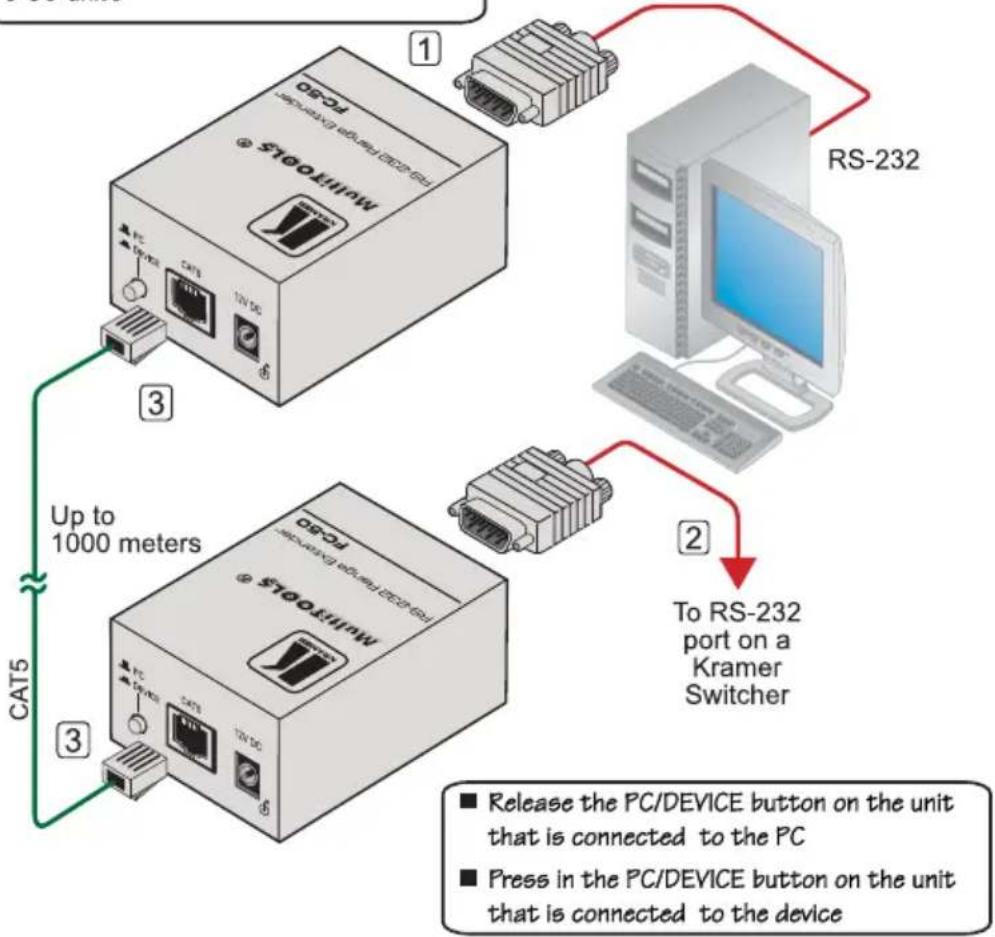
This quick start chart summarizes the basic setup and operation steps.
Step 1: Connect the Inputs and the outputs
1 Connect the PC to the RS-232 port 2 Connect the RS-232 port to the switcher 3 Connect the CAT 5 cable between the FC-50 units
flowchart
graph TD
    A["MultiTools"] -->|1| B["RS-232"]
    A -->|3| C["RS-232 port on a Kramer Switcher"]
    C -->|2| D["To RS-232 port on a Kramer Switcher"]
    A -->|3| E["CAT5"]
    E --> F["Up to 1000 meters"]
    style A fill:#f9f,stroke:#333
    style B fill:#ccf,stroke:#333
    style C fill:#ccf,stroke:#333
    style D fill:#cfc,stroke:#333
    style E fill:#fcc,stroke:#333
    style F fill:#ffc,stroke:#333
Step 2: Connect the power
If required:
Set the CROSSED/STRAIGHT CONNECTION switch to CROSSED if a crossed cable is connected between the RS-232 port and the PC/device
Set the CROSSED/STRAIGHT CONNECTION switch to STRAIGHT if a straight cable is connected between the RS-232 port and the PC/device
3 Overview
The high-quality Kramer MultiTOOLS FC-50 RS-232 Range Extender can connect either to a PC or to a device (for example, a switcher). By connecting two units via a CAT 5 cable, the PC can control the switcher over a range of up to 1000 meters (3300 feet).
In particular, the FC-50 features:
- Bidirectional RS-232 operation
• The Power Connect feature - A CONNECTION switch to select between a crossed and a straight connection
- A PC/DEVICE pushbutton that is pressed or released if a device or a PC, respectively, are connected to the RS-232 port
- 12V DC power
3.1 About the Power Connect Feature
The Power Connect feature applies as long as the cable can carry power. This feature is available when using STP cable, and the distance does not exceed 50m on standard CAT 5 cable. For longer distances, heavy gauge cable should be used ^1 . For units which are connected via RJ-45 connectors, make sure that the shield of the STP cable is connected to the metal casing of the connectors on both ends of the cable. For units which are connected via terminal block connectors, the shield of the STP cable must be connected to a ground terminal on the units at both ends (use the ground terminal of the power supply connection if necessary).
For a CAT 5 cable exceeding a distance of 50m, separate power supplies should be connected to the transmitter and to the receiver simultaneously.
3.2 Shielded Twisted Pair (STP) / Unshielded Twisted Pair (UTP)
We recommend that you use Shielded Twisted Pair (STP) cable. There are different levels of STP cable available, and we advise you to use the best quality STP cable that you can afford. Our non-skew-free cable, Kramer BC-STP is intended for analog signals where skewing is not an issue. For cases where there is skewing, our UTP skew-free cable, Kramer BC-XTP, may be used. Bear in mind, though, that we advise using STP cables where possible, since the compliance to electromagnetic interference was tested using those cables.
Although Unshielded Twisted Pair (UTP) cable might be preferred for long range applications, the UTP cable should be installed far away from electric cables, motors and so on, which are prone to create electrical interference. However, since the use of UTP cable might cause inconformity to electromagnetic standards, Kramer does not commit to meeting the standard with UTP cable.
3.3 Recommendations for Achieving the Best Performance
To achieve the best performance:
- Use only good quality connection cables ^1 to avoid interference, deterioration in signal quality due to poor matching, and elevated noise levels (often associated with low quality cables).
- Avoid interference from neighboring electrical appliances that may adversely influence signal quality and position your Kramer FC-50 away from moisture, excessive sunlight and dust
4 Your FC-50 RS-232 Range Extender
Figure 1 and Table 1 define the FC-50 RS-232 Range Extender:
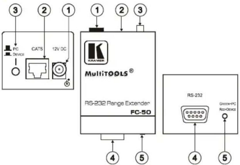
Figure 1: FC-50 RS-232 Range Extender
Table 1: FC-50 RS-232 Range Extender Features
| # | Feature Function | ||
| 1 | 12V DC | +12V DC connector for powering the unit | |
| 2 | CAT 5 RJ-45 Connector | Connect to ^1 the CAT 5 RJ-45 connector on the other FC-50 unit | |
| 3 | PC / DEVICE Button | Press when a device is connected to the RS-232 portRelease when a PC is connected to the RS-232 port | |
| 4 | RS-232 9-pin D-sub Connector | Connects to either a PC or a devicePINs 2, 3 and 5 are passed through the device | |
| 5 | GREEN=PCRED=DEVICE | LED | Lights in green when the PC/DEVICE button is released and in red when the PC/DEVICE button is pressed |
Figure 2 and Table 2 define the FC-50 underside:
Table 2: FC-50 RS-232 Range Extender Underside Features
| Feature Function | |
| CROSSED / STRAIGHT CONNECTION Switch | Set to CROSSED for a crossed wire connection ^2 between the RS-232 port and the PC/deviceSet to STRAGHT for a straight wire connection between the RS-232 port and the PC/device |
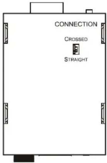
Figure 2: FC-50 RS-232 Range Extender Underside
5 Connecting the FC-50 RS-232 Range Extender
To connect two FC-50 units, as illustrated in the example in Figure 3, do the following:
- Connect a PC to the RS-232 port of the first FC-50 unit and release the PC/DEVICE button.
- Connect the RS-232 port of the second FC-50 unit to a device (for example, a switcher) and push in the PC/DEVICE button.
- Connect the CAT 5 RJ-45 connector of the first unit to the CAT 5 RJ-45 connector of the second FC-50 unit via UTP cabling.
- Set the CONNECTION switch independently on both units as follows:
■ STRAIGHT for a straight wire connection ^1 between the RS-232 port and the PC/device
- CROSSED for a crossed wire connection ^2 between the RS-232 port and the PC/device
- Connect the 12V DC power adapter to the power socket on the FC-50 and connect the adapter to the mains electricity (not illustrated in Figure 3).
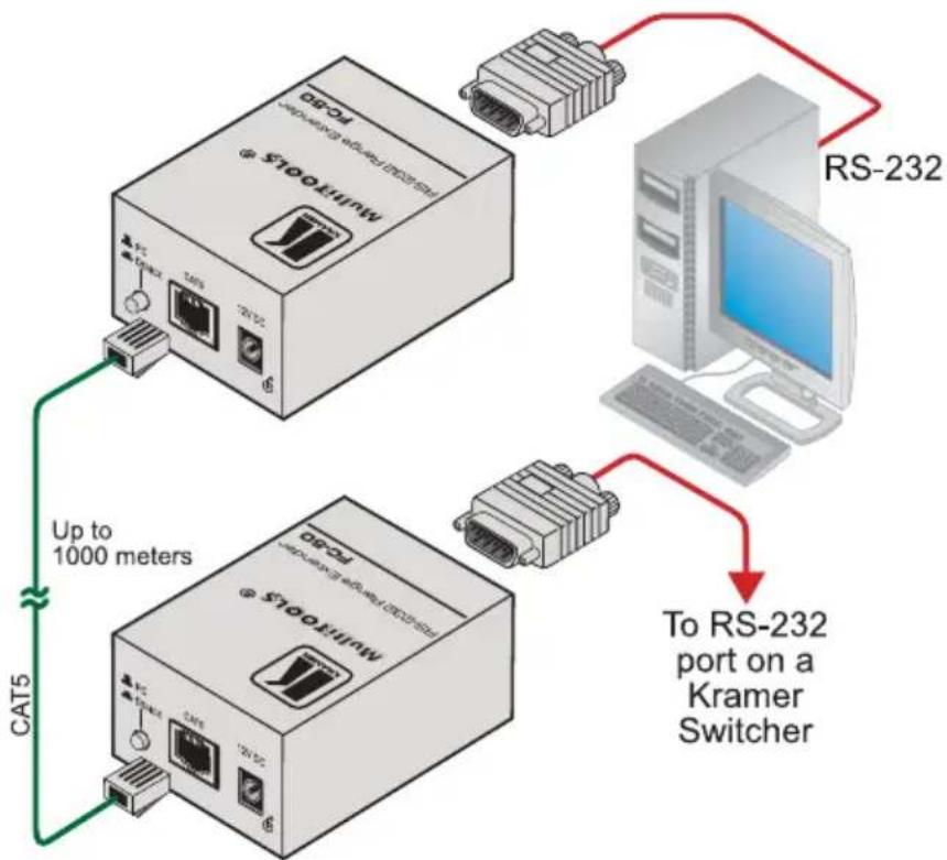
flowchart
graph TD
    A["MultiTools"] -->|Up to 1000 meters| B["RS-232"]
    A -->|CAT5| C["Kamer Switcher"]
    B --> D["To RS-232 port on a Kramer Switcher"]
Figure 3: Connecting the FC-50 RS-232 Range Extender
5.1 Wiring the CAT 5 LINE IN / LINE OUT RJ-45 Connectors
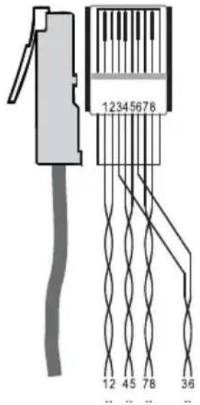
Table 3 and Figure 4 define the UTP CAT 5 PINOUT, using a straight pin to pin cable with RJ-45 connectors:
Table 3: CAT 5 PINOUT
| EIA /TIA 568A EIA /TIA | 568B | ||
| PIN Wire Color PIN Wire Color | Color | ||
| 1 Green / White 1 Orange / | White | ||
| 2 Green 2 | Orange | ||
| 3 Orange / White 3 Green / | White | ||
| 4 Blue 4 | Blue | ||
| 5 Blue / White 5 Blue / White | |||
| 6 Orange | 6 | Green | |
| 7 Brown / White | 7 Brown / White | ||
| 8 Brown | 8 | Brown | |
| Pair 1 | 4 and 5 | Pair 1 | 4 and 5 |
| Pair 2 | 3 and 6 | Pair 2 | 1 and 2 |
| Pair 3 | 1 and 2 | Pair 3 | 3 and 6 |
| Pair 4 | 7 and 8 | Pair 4 | 7 and 8 |
Figure 4: CAT 5 PINOUT
6 Technical Specifications
The FC-50 technical specifications are shown in Table 4:
Table 4: Technical Specifications ^1 of the FC-50
| PORTS: | RS-232 on a 9-pin D-sub connector ^2 , 1 CAT 5 RJ-45 connector |
| BAUD RATES: | Up to 115.2kbaud |
| DISPLAY: | GREEN=PC/RED=DEVICE LED |
| DIMENSIONS: | 5.32cm x 7.25cm x 4.2cm (2.09" x 2.85" x 1.65"), W, D, H |
| POWER SOURCE: 12V | DC, 42mA |
| WEIGHT: | 0.3kg (0.67lbs) approx. |
LIMITED WARRANTY
Kramer Electronics (hereafter Kraments this product free from defects in material and workmanship under the following terms.
HOW LONG IS THE WARRANTY
Labor and parts are warranted for seven years from the date of the first customer purchase.
WHO IS PROTECTED?
Only the first purchase customer may enforce this warranty.
WHAT IS COVERED AND WHAT IS NOT COVERED
Except as below, this warranty covers all defects in material or workmanship in this product. The following are not covered by the warranty:
- Any product which is not distributed by Kramer, or which is not purchased from an authorized Kramer dealer. If you are uncertain as to whether a dealer is authorized, please contact Kramer at one of the agents listed in the Web site www.kramerelectronics.com.
- Any product, on which the serial number has been defaced, modified or removed, or on which the WARRANTY VOID IF TAMPERED sticker has been torn, reattached, removed or otherwise interfered with.
- Damage, deterioration or malfunction resulting from:
i) Accident, misuse, abuse, neglect, fire, water, lightning or other acts of nature
ii) Product modification, or failure to follow instructions supplied with the product
iii) Repair or attempted repair by anyone not authorized by Kramer
iv) Any shipment of the product (claims must be presented to the carrier)
v) Removal or installation of the product
vi) Any other cause, which does not relate to a product defect
vii) Cartons, equipment enclosures, cables or accessories used in conjunction with the product
WHAT WE WILL PAY FOR AND WHAT WE WILL NOT PAY FOR
We will pay labor and material expenses for covered items. We will not pay for the following:
- Removal or installations charges.
- Costs of initial technical adjustments (set-up), including adjustment of user controls or programming. These costs are the responsibility of the Kramer dealer from whom the product was purchased.
- Shipping charges.
HOW YOU CAN GET WARRANTY SERVICE
- To obtain service on you product, you must take or ship it prepaid to any authorized Kramer service center.
- Whenever warranty service is required, the original dated invoice (or a copy) must be presented as proof of warranty coverage, and should be included in any shipment of the product. Please also include in any mailing a contact name, company, address, and a description of the problem(s).
- For the name of the nearest Kramer authorized service center, consult your authorized dealer.
LIMITATION OF IMPLIED WARRANTIES
All implied warranties, including warranties of merchantability and fitness for a particular purpose, are limited in duration to the length of this warranty.
EXCLUSION OF DAMAGES
The liability of Kramer for any effective products is limited to the repair or replacement of the product at our option. Kramer shall not be liable for:
- Damage to other property caused by defects in this product, damages based upon inconvenience, loss of use of the product, loss of time, commercial loss; or:
- Any other damages, whether incidental, consequential or otherwise. Some countries may not allow limitations on how long an implied warranty lasts and/or do not allow the exclusion or limitation of incidental or consequential damages, so the above limitations and exclusions may not apply to you.
This warranty gives you specific legal rights, and you may also have other rights, which vary from place to place.
NOTE: All products returned to Kramer for service must have prior approval. This may be obtained from your dealer.
This equipment has been tested to determine compliance with the requirements of:
EN-50081: "Electromagnetic compatibility (EMC);
generic emission standard.
Residential, commercial and light industry"
EN-50082: "Electromagnetic compatibility (EMC) generic immunity standard.
Part 1: Residential, commercial and light industry environment".
CFR-47: FCC* Rules and Regulations:
Part 15: "Radio frequency devices
Subpart B Unintentional radiators"
CAUTION!
Servicing the machines can only be done by an authorized Kramer technician. Any user who makes changes or modifications to the unit without the expressed approval of the manufacturer will void user authority to operate the equipment.
Use the supplied DC power supply to feed power to the machine.
☒ Please use recommended interconnection cables to connect the machine to other components.
* FCC and CE approved using STP cable (for twisted pair products)
For the latest information on our products and a list of Kramer distributors, visit our Web site: www.kramerelectronics.com where updates to this user manual may be found. We welcome your questions, comments and feedback.

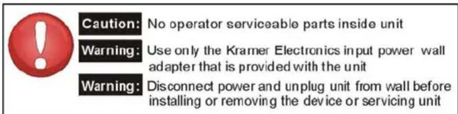
Caution
Safety Warning:
Disconnect the unit from the power supply before opening/servicing.

CE
- Kramer Electronics, Ltd.
- USER MANUAL
- Contents
- Figures
- Tables
- Introduction
- Getting Started
- Quick Start
- If required:
- Overview
- About the Power Connect Feature
- Shielded Twisted Pair (STP) / Unshielded Twisted Pair (UTP)
- Recommendations for Achieving the Best Performance
- Your FC-50 RS-232 Range Extender
- Connecting the FC-50 RS-232 Range Extender
- Wiring the CAT 5 LINE IN / LINE OUT RJ-45 Connectors
- Technical Specifications
- LIMITED WARRANTY
- HOW LONG IS THE WARRANTY
- WHO IS PROTECTED?
- WHAT IS COVERED AND WHAT IS NOT COVERED
- WHAT WE WILL PAY FOR AND WHAT WE WILL NOT PAY FOR
- HOW YOU CAN GET WARRANTY SERVICE
- LIMITATION OF IMPLIED WARRANTIES
- EXCLUSION OF DAMAGES
- CAUTION!
- Safety Warning:
Brand : Kramer
Model : FC-50
Category : Audio/video extender