
ATEM 1 - Uncategorized Blackmagic Design - Free user manual and instructions
Find the device manual for free ATEM 1 Blackmagic Design in PDF.


| Product Type | Live Production Switcher (M/E style) |
| Brand | Blackmagic Design |
| Model | ATEM 1 (ATEM 1 M/E Production Studio 4K) |
| Video Standards | SD, HD, Ultra HD up to 2160p59.94 |
| Number of Inputs | 10 (selectable SDI/HDMI on input 1) |
| Video Outputs | 1 Program SDI + 1 Program HDMI, 1 Multi View, 3 Auxiliary SDI |
| Audio Inputs | Embedded SDI/HDMI, analog XLR and 1/4" jack |
| Audio Features | Built-in audio mixer, Fairlight parametric EQ, dynamics, talkback |
| Multi View | 10 views (2 large + 8 small) on SDI/HDMI, customizable labels |
| Transition Types | Cut, Auto, Mix, Dip, Wipe, DVE, Stinger (graphic) |
| Keyers | Upstream and downstream keyers (luma, linear, chroma, pattern, DVE) |
| Media Players | 2 internal media players for graphics and clips |
| Camera Control | Blackmagic camera control via SDI, DaVinci Resolve primary color corrector |
| HyperDeck Control | Up to 4 HyperDeck recorders via SDI/HDMI and Ethernet |
| Network | Ethernet for control panels (fixed IP default 192.168.10.240) |
| Control Options | Free software control panel (Mac/Windows), optional hardware panels |
| Power Supply | 100-240V AC, 50/60 Hz (internal, IEC connector) |
| Safety | Must be connected to earthed mains outlet; adequate ventilation required |
| Serviceability | No user-serviceable parts; contact Blackmagic Design service center |
| Manual Languages | English, Japanese, French, German, Spanish, Chinese, Korean, Russian, Italian, Turkish |
Frequently Asked Questions - ATEM 1 Blackmagic Design
User questions about ATEM 1 Blackmagic Design
0 question about this device. Answer the ones you know or ask your own.
Ask a new question about this device
Download the instructions for your Uncategorized in PDF format for free! Find your manual ATEM 1 - Blackmagic Design and take your electronic device back in hand. On this page are published all the documents necessary for the use of your device. ATEM 1 by Blackmagic Design.
USER MANUAL ATEM 1 Blackmagic Design
Installation and Operation Manual
ATEM Production Studio Switchers
June 2019
English, 日本語, Français, Deutsch, Español, 中文, 한국어, Русский, Italiano and Türkçe.
Languages
To go directly to your preferred language, simply click on the hyperlinks listed in the contents below.
English 3
日本語 235
Français 468
Deutsch 701
Español 934
中文 1167
한국어 1400
Русский 1634
Italiano 1867
Türkçe 2100

natural_image
Circular portrait photo of a smiling man in a dark shirt against a gray background (no text or symbols)Welcome
Thank you for purchasing an ATEM switcher for your live production work!
If you're new to live production switchers, then you're about to become involved in the most exciting part of the television industry and that's live production! There is nothing like live production and it's so easy to become addicted to the adrenaline rush of editing in real time while the live event unfolds before your eyes. It's real television the way it should be!
Previously, broadcast quality live production has always been way too high in cost for most people to afford, while affordable switchers lacked broadcast features and quality. The new ATEM switchers change this and you can use them for the most amazing professional live production results. We hope you get years of use from them and have lots of fun with your live production!
This instruction manual should contain all the information you'll need for installing your ATEM Production Switcher. The ATEM switcher includes a software control panel which you can run on your computer or you can purchase a hardware based broadcast control panel separately. The computer and control panels connect to your ATEM switcher via a network cable and you can directly connect them together without any extra equipment!
Please check the support page on our web site at www.blackmagicdesign.com for the latest version of software for your ATEM switcher. Simply connect your computer to the ATEM switcher and the ATEM broadcast control panel via USB to update software so you get all the latest features! When downloading software, please register with your information so we can keep you updated when new software is released. We are constantly working on new features and improvements, so we would love to hear from you!
Grant Petty
Grant Petty
CEO Blackmagic Design
Contents
ATEM Production Studio Switchers
Getting Started 6
Introducing ATEM 6
What is an M/E Switcher? 6
What is an A/B Direct Switcher? 8
Understanding the ATEM Switcher 9
Plugging in Multi View Monitoring 10
Plugging in an ATEM Hardware Panel 11
Installing Blackmagic ATEM Software on Mac 13
Installing Blackmagic
ATEM Software on Windows 14
Plugging in your Computer 15
Switcher Settings 17
Plugging in Cameras and Other
Video Sources 21
Plugging in Audio 22
Connecting to a Network 22
Changing the Switcher Network Settings 23
Understanding ATEM Hardware
Panel Network Settings 24
Setting the Switcher IP Location 24
Changing the Hardware Panel
Network Settings 26
Setup Workflow with ATEM Constellation 8K 28
Updating the Software 29
How to update the ATEM Software 29
Updating the Switcher Software 30
Updating an ATEM Hardware Panel 30
Connecting Video Outputs 31
Using the ATEM Constellation 8K
Front Panel 33
Performing a Transition 33
Fading the Downstream Key 1 37
Fade to Black 38
Using the Lock Button 38
Using the LCD Menus 38
Using Talkback 39
The Call Button 39
Using ATEM Software Control 40
Preference Settings 40
General Preferences 40
Button Mapping 41
Switcher Control Panel 41
Using Keyboard Hot Keys 42
Media Manager 42
Audio Mixer 43
Camera Control 44
Switcher Settings 44
Using the Software Control Panel 45
Mix Effects 45
Program Bus Source Select Buttons 46
Preview Bus Source Select Buttons 46
Transition Control and Upstream Keyers 46
Downstream Keyers 48
Fade to Black (FTB) 48
Processing Palettes 48
Using the Audio Mixer 51
Shaping your Audio Mix using
Advanced Fairlight Controls 55
Input Level 55
Using the 6 Band Parametric Equalizer 56
Parametric Equalizer 56
Dynamics Controls 58
Dynamics Controls Characteristics 60
Fairlight Controls Workflow Guide 61
Navigating the Browse Window
on the Media Page 62
Changing Switcher Settings 64
General Settings 64
Multi View Settings 69
Labels Settings 70
Remote Settings 71
Controlling Auxiliary Outputs 72
Routing Auxiliary Outputs 72
Program/Preview and A/B Direct
Transition Control 72
Saving and Restoring Switcher Settings 73
Using Camera Control 74
DaVinci Resolve Primary Color Corrector 81
Using a DaVinci Resolve Micro Panel 83
HyperDeck Control 85
Introducing HyperDeck Control 85
Connecting HyperDecks 85
HyperDeck Settings 86
Controlling HyperDecks with
ATEM Software Control 87
Controlling HyperDecks with
ATEM Hardware Panels 89
Using ATEM Hardware Panels 97
Using the ATEM 1 M/E Advanced Panel 98
Using the Control Panel 99
Button Mapping 106
Performing Transitions using
ATEM Hardware Panels 106
Cut Transitions 107
Auto Transitions 108
Mix Transitions 109
Dip Transitions 110
Wipe Transitions 112
DVE Transitions 114
Performing a Graphic Transition 116
Manual Transitions 118
Using the ATEM 1 M/E Broadcast Panel 118
Using the Control Panel 118
Button Mapping 126
Using the ATEM 2 M/E Broadcast Panel 126
Using the Control Panel 127
Button Mapping 134
Operating your ATEM Switcher 136
Internal Video Sources 136
Black 136
Color Bars 136
Color Generators 136
Media Players 137
Performing Transitions 138
Cut Transitions 138
Auto Transitions 140
Mix Transitions 142
Dip Transitions 143
Wipe Transitions 145
Performing a Stinger Transition 147
DVE Transitions 149
Performing a Graphic Transition 152
Manual Transitions 154
Preview Transition 154
Keying using ATEM Switchers 155
Understanding Keying 155
Luma Key 155
Linear Key 156
Pre multiplied Key 156
Performing an Upstream Luma/Linear Key 157
Performing a Downstream Luma/Linear Key 159
Chroma Key 160
Performing an Upstream Chroma Key 161
Performing an Advanced Chroma Key 163
Pattern Key 165
Performing an Upstream Pattern Key 166
DVE Key 168
Performing an Upstream DVE Key 169
Key Masking 171
Fly Key 171
Performing Upstream Keyer Transitions 171
Performing Downstream Keyer Transitions 173
Using Adobe Photoshop with ATEM 174
Using Auxiliary Outputs 175
Using SuperSource (Picture in Picture) 178
Using Macros 181
What is a Macro? 181
The Macros Window in
ATEM Software Control 181
Recording Macros 182
Recording a Macro using
ATEM Software Control 182
Building Large Macros 185
Recording Macros using an
ATEM 1 M/E Broadcast Panel 187
Recording Macros using an
ATEM 2 M/E Broadcast Panel 190
Recording Macros using
ATEM 1 M/E Advanced Panel 194
Using ATEM Camera Control Panel 196
Changing Network Settings 198
Camera Control Panel Layout 199
Controlling Cameras 204
Using Tally 211
Sending Tally Signals via
a GPI and Tally Interface 211
Using Audio 214
Connecting other Audio Sources 214
Using Embedded SDI and HDMI
Audio Sources 214
Using MADI with ATEM Constellation 8K 215
Using a Third Party Audio Mixer
Control Surface 217
Adapter Cables for Talkback
and Camera Control 219
Developer Information 220
Blackmagic SDI Camera Control Protocol 220
Example Protocol Packets 227
Blackmagic Embedded
Tally Control Protocol 228
Visca Commands for PTZ control via SDI 230
Help 231
Regulatory Notices 232
Safety Information 233
Warranty 234
Getting Started
Introducing ATEM
ATEM Production Studio Switchers are professional broadcast grade digital production switchers capable of switching and processing a variety of video sources in live video production and broadcast environments. The switcher uses the current and familiar M/E (Mix Effects) based design with software and hardware control options that provides an intuitive, fast and easy to use workflow for program/preview switching! If you're used to the older A/B direct switcher style, ATEM switchers also support A/B direct switching which makes it easy to get started!
An ATEM production switcher only requires an ATEM production switcher and the included software control panel to get started. Then you can optionally add one or more hardware control panels if you need a more advanced solution.
Multiple control panels can be connected to control the same switcher by simple Ethernet connections. The ATEM software control panel can be installed on as many computers as you like at no extra cost.
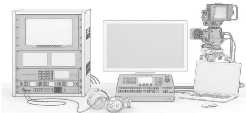
natural_image
Illustration of a vintage computer setup with monitor, keyboard, headphones, and camera (no text or symbols visible)You can build a custom ATEM live broadcast system to suit your individual requirements
What is an M/E Switcher?
If you have used low cost switchers before, then these might not have used the mix effects style of operation that's commonly called an M/E style of operation. If you have used an M/E style switcher, then you might want to skip ahead to install and get working with your new ATEM switcher!
When you're starting out with a switcher for the first time, the ATEM can look a little intimidating with all its buttons and knobs, however it's all very logically laid out so it's very simple to use!
ATEM is a true high-end broadcast switcher that operates using the M/E workflow standards used in the broadcast industry. This means once you get familiar with how it works, you will feel instantly at home on virtually any switcher used in broadcast today.
The M/E style of operation has been developed over decades to help eliminate errors when switching live events and is a broadcast standard. It's extremely easy to see what's going on at any time so you don't get confused and make mistakes. The M/E style of operation lets you check the sources you are about to switch on air, as well as try effects before using them on air. You can see buttons for each keyer and transition, so you instantly know what's going on and what's about to happen.
The best way to learn about how your ATEM works is to grab your switcher and play with it while referencing this manual! You might want to jump ahead and install your switcher before reading the rest of this section!
To start, the most visible part of an M/E based control panel is the fader bar and the program and preview rows of source buttons!
The program bus source select buttons are used to hot switch sources to the program output. The source currently on air is indicated by a button that is illuminated red. Be careful when selecting sources on this row, as they will instantly be switched on air!
A safer and more orderly way to do transitions is to select them on the preview row and then use a transition to cut or transition them on air.
The bottom row of buttons is the preview bus source selection. This is where you will spend most of your time selecting sources about to go on air. This selected source is sent to the program output when the next transition occurs. The next transition can be triggered by pushing the cut button, the auto button, or by toggling the fader bar. You can select between a mix, dip, wipe, DVE or other transition depending what you have selected in the transition control section.
This is a very powerful way to use a switcher, because you can select your source on the preview row and see it on the preview video output to confirm that you have the correct source before you select the transition you want. You can see what's happening at all stages so it's hard to make mistakes. Only the M/E style of operation allows you to keep track of what's going on.
You also might notice that once your transition is complete, the sources selected on the preview and program rows swap over. This is because the source you selected on the preview row is now the new on air source, so it becomes selected on the program row once the transition is complete. Remember the program row always shows what's on air.
You will also see both the program and preview buttons illuminate red when doing an auto transition, as for a short time, they are both on air while the transition occurs.
There are multiple types of transitions available and they can be selected in the transition control. On the ATEM 1 M/E Broadcast Panel there are two transition type buttons. One is labeled DIP/MIX and the other is labeled DVE/wipe. Selecting these buttons selects mix and wipe transitions, however pressing shift and then selecting mix or wipe allows more types of transitions, dip and DVE. You can also select both buttons for a stinger transition. On the ATEM 2 M/E Broadcast Panel there are four transition type buttons. One is labeled DIP/MIX and the others are labeled wipe, stng and DVE. Selecting these buttons selects mix, wipe, stinger and DVE transitions. However pressing shift and then selecting mix allows for dip transitions. If you are using the ATEM software control panel on your computer, all transition types have their own button and no shifting is necessary to select any of them. Extra details on how all these transitions work are provided later in this instruction manual.
The other concept that is important to know about M/E style switchers, including ATEM, is the video on the program and preview rows is technically called the background video. This is because the upstream (effects) keyers and downstream keyers will overlay on top of this source. So you can load graphics into the keyers and see them with the preview video and when keys are turned on, you will see the overlay on top of the program video. This is very powerful and allows multiple layers to be built up.
Another great advantage of the ATEM M/E style of operation is you can tie keyers to the transition. This means when you do a mix transition, you can also fade on or off keyers at the same time. This allows you to build up a composition and then bring the whole lot on air at the same time. This is what the next transition buttons do and you can select background for normal transitions, or select one or more keyers to transition them on air.
You can even press multiple buttons on the hardware control panel to tie multiple keys and the background at the same time. There are also dedicated downstream key tie buttons to tie downstream keyers to the transition. Downstream keys also have dedicated cut and mix buttons and so are very flexible. Downstream keyers are always layered over the top of everything including the transition, so are a great place to key bugs and logos!
When your live production is finishing, it's nice to have a dedicated fade to black (FTB) control to fade everything to black! You can see the dedicated fade to black control on the right side of the keyboard. This lets you fade everything to black and helps make sure you don't miss a layer. Fade to black is at the extreme end of the processing chain so you get a clean fade of all sources.
The last part of an M/E style switcher is the select bus. This is above the program row and simply allows sources to be selected for effects processing and other purposes, and there is a label above this to show what you're switching. The select bus is commonly used to select key inputs, and aux outputs. It's a clean switch, so when used to select aux outputs, you get a clean cut.
As you can see by this quick overview, M/E style of operation allows confident live production with good feedback on what's going on and the state of your switcher and programming at any point in your production. Once you learn the M/E style of operation, you can move between models of production switchers with little retraining as they all work the same!
What is an A/B Direct Switcher?
If you have been using video switchers for a long time, then you might be used to older-style A/B direct switchers and you can easily set your ATEM switcher to A/B direct switching in the ATEM software preferences. See the Transition Control section of this instruction manual for details about where to change this setting.
A/B direct switchers have an A bus and a B bus. One bus is the program bus which shows a red button for the current program output. The other is the preview bus which has a green button for the preview video. As you move the fader bar up and down, the buses switch so that the red program button follows the fader handle. This is where A/B direct switching is really easy to use as the buttons stay lit in the same positions and just switch color between green and red.
A/B direct switching becomes a little more confusing when the fader bar is not used to make the switch. If you use a cut or auto transition button to bring your preview source on air, or if you use more than one control panel connected to your switcher, the fader bar won't have moved on the control panel that you are using. The red program output always follows the fader bar handle and, as you haven't moved it, the red program light has to move to another button on the same row and the green preview light has to move to another button in its row.
This can become quite confusing when sometimes using the fader bar to make switches, and sometimes not, as the rows containing your preview and program buttons will sometimes switch and sometimes stay where they are which has the potential to lead to mistakes.
This is why modern M/E style switching is preferable because you'll always find your green preview button in the row labelled Preview, and the red program button in the row labelled Program. It's always consistent and there are no surprises with M/E style switching.
Understanding the ATEM Switcher
The ATEM switcher provides all the video processing as well as all video input and output connectors, connection for control panels and power connections. You use the switcher by connecting and using various types of control panels. This allows the switcher to be located remotely, such as in machine rooms where it's closer to the connected video devices, while the control panel can be placed in a location from where it is easier to run production.
ATEM Constellation 8K is a switcher capable of switching up to 40 external Ultra HD inputs via independent 12G-SDI connectors, or 10 8K inputs via quad link 12G-SDI. This switcher features six 8K outputs plus an 8K multi view output, or 4 Ultra HD multi views. You can switch video from HD 1080p59.94, Ultra HD 2160p59.94, all the way up to 8K 4320p59.94. The built in control panel with LCD and talkback lets you switch directly from the front panel so you can quickly confirm all your sources and test your production setup before going to air.


natural_image
Front view of a black rack-mounted network device with multiple ports and connectors (no visible text or labels)ATEM Constellation 8K
ATEM Production Studio 4K supports SD, HD and Ultra HD video and is capable of switching 8 external inputs from its SDI and HDMI connectors. The front panel keypad lets you select instantly between auxiliary output sources and the small LCD gives you instant feedback on the status of the auxiliary output.


natural_image
Front view of a gray electronic device rear panel with ports, connectors, and a power outlet (no visible text or symbols)ATEM Production Studio 4K
ATEM 1 M/E Production Studio 4K supports SD, HD and Ultra HD video and is capable of switching 10 external inputs from its SDI and HDMI connectors. Input 1 is selectable between the HDMI Input 1 and SDI Input 1 connector. The front panel keypad lets you select instantly between 3 auxiliary output sources and the small LCD gives you instant feedback on the status of the auxiliary outputs.


natural_image
Front view of a network equipment rack with ports, connectors, and a USB port (no visible text or labels)ATEM 1 M/E Production Studio 4K
ATEM 2 M/E Production Studio 4K supports SD, HD and Ultra HD video and is capable of switching 20 external inputs from its SDI and HDMI connectors. Input 1 is selectable between the HDMI Input 1 and SDI Input 1 connector. The front panel keypad allows on-the-fly selection of the 6 auxiliary output sources and the large LCD gives instant confirmation of your aux output content.
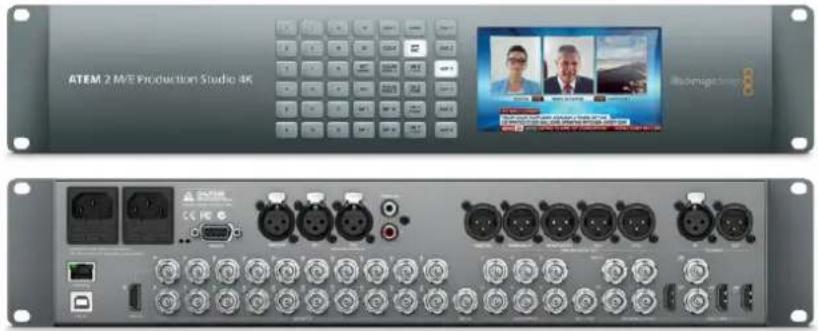
natural_image
Front and back view of a ATEM 2 M/E Production Studio 4K device showing front panel, back panel with multiple ports and a screen displaying video callouts (no readable text or symbols on main components)ATEM 2 M/E Production Studio 4K
ATEM 4 M/E Broadcast Studio 4K supports HD and Ultra HD video and is capable of switching 20 external SDI inputs. Features include 4 media players, advanced chroma keying, Ultra HD multi views and 12G-SDI support for Ultra HD frame rates up to 2160p59.94 on a single BNC connector. The front panel keypad lets you select between 6 auxiliary output sources and you can monitor the outputs on the large built in LCD.
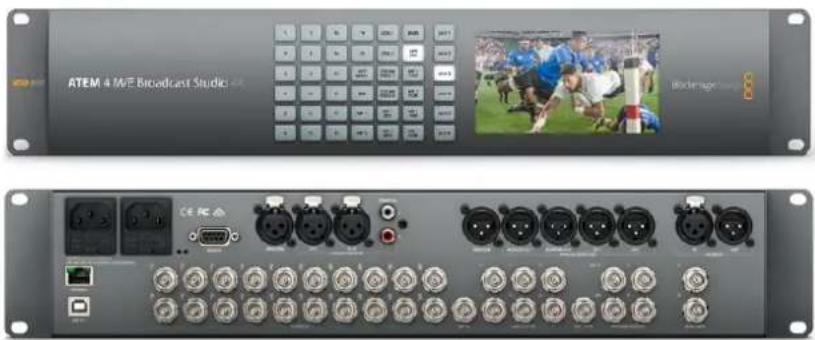
natural_image
Front and back view of a ATEM 4 M/E Broadcast Studio rack with multiple ports and an embedded video player (no visible text or symbols on the device itself)ATEM 4 M/E Broadcast Studio 4K
NOTE If you have an ATEM 2 M/E Broadcast Studio 4K, you can update your switcher to ATEM 7.3 or later and enable all the same features that are available on ATEM 4 M/E Broadcast Studio 4K. This means you can update your ATEM 2 M/E Broadcast Studio 4K switcher to an ATEM 4 M/E Broadcast Studio 4K simply by updating the internal software.
Plugging in Multi View Monitoring
The ATEM can be a little intimidating when first seen, especially since some models have no controls to access, just lots of connectors! So the first step is to plug in power and a monitor and see it working! ATEM switchers have a front control panel with a built in LCD so you only need to connect power to see them working!
A convenient way to check that your ATEM is powered on and working correctly is to plug an HDMI television or SDI monitor into the multi view output on the right side of the rear panel.
You should see 8 video boxes at the bottom, and two larger boxes at the top, all bound by white borders. Each box will have a label.
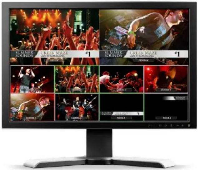
If you see this video output, then your ATEM is powered on and running fine! All you need to do now is plug in some control panels and video sources so you can start using your switcher!
If you don't see the multi view output on your television, check the connections and cables are correct. You need to plug into the multi view connector on the rear of the ATEM. Next, check if your television is compatible with the video standard set in the ATEM. If your television is not compatible with the set standard, don't worry, its easy to change once you connect your computer to the ATEM.
If you still don't see the multi view on your television, then double check your power connection to make sure your ATEM is powered on.
Plugging in an ATEM Hardware Panel
If you have purchased an ATEM hardware panel, then you won't want to wait to plug in your computer, as it's much more fun to plug in the hardware panel first!
Plugging in the broadcast panel is simple, because it's already set to the correct network settings to plug into your switcher without any changes required.
1 Plug in the power to the hardware panel. For redundant power on ATEM Broadcast Panels with built in power supplies, plug in a second IEC power cord. For ATEM Broadcast Panels with external power supplies, redundant power can be provided by purchasing a second power supply and plugging it into the second power connector.
TIP ATEM 1 M/E Advanced Panel has a 12v XLR input for portable field use when powered by a battery, or for backup 12 volt power provided by an alternative power source, such as a UPS.
2 Plug one end of an Ethernet cable into one of the hardware panel's Ethernet ports. Either of the ports will do, as there is an Ethernet switch inside the panel, so both ports work the same.
3 Plug the other end of the same cable into the Ethernet port labeled Switcher Control on the switcher.
If everything is working fine, you should see the lights on the Ethernet port start to flicker, and the broadcast panel should come alive with buttons illuminated, and the main display on the panel should say 'ATEM Production Switcher'. The power status indicator lights on the front of the panel will also illuminate. On the ATEM 1 M/E Advanced Panel, the LCD will show the source names for sources switched to the program and preview outputs, plus other settings.
If you don't see this appear, then check that the switcher and the hardware panel are powered correctly and/or power connectors are firmly plugged in.
If things are still not working, then you should make sure that your ATEM hardware panel is connected directly to your switcher and not via a network. If this is correct, then the most likely cause of the problem is the hardware panel and the switcher have IP addresses in different ranges. In this case, you will need to check and set these as described later in this manual.
If you need to manually set the network settings, then you might need to get the assistance of a technically minded friend who understands how to set IP addresses. By default, the switcher is set to a fixed IP address of 192.168.10.240, and the ATEM broadcast panels are set to a fixed IP of 192.168.10.10, so when connected directly they should communicate without problem. Similarly, ATEM 1 M/E Advanced Panel is set to a unique default address of 192.168.10.60. Go to the 'Connecting to a Network' section in this manual to see how to check and set your switcher to these addresses. Then it should work OK with a direct connection between the hardware panel and the switcher.
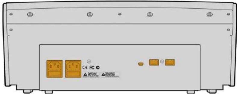
ATEM 1 M/E Broadcast Panel rear connectors

natural_image
Technical line drawing of a mechanical device with no visible text or symbolsATEM 2 M/E Broadcast Panel rear connectors
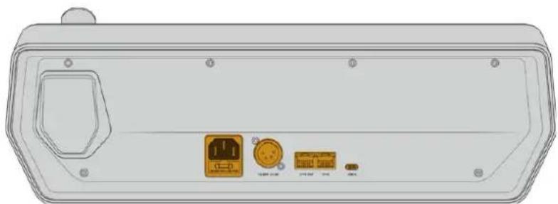
natural_image
Top-down view of a device rear panel showing ports and connectors (no text or symbols visible)ATEM 1 M/E Advanced Panel rear connectors
Installing Blackmagic ATEM Software on Mac
Before installing any software you will need administrator privileges. It is also a good idea to uninstall any previous versions of ATEM software present on your computer.
1 Ensure you have the very latest driver. Visit www.blackmagicdesign.com/support
2 Open the "Blackmagic ATEM Switchers" folder from the disc or downloaded disk image and launch the "Blackmagic ATEM Switchers Installer Software".
3 Click Continue, Agree and Install buttons and the software will be installed on your system.
4 Now restart your computer to enable the new software drivers.
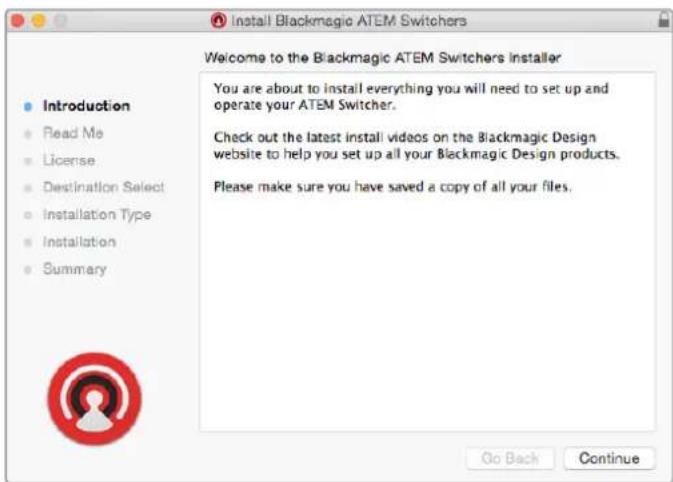
Follow install prompts
Plugins and Applications that are Installed
The ATEM Switchers software installs the following components which are used by ATEM Switchers:
- ATEM Software Control
- Blackmagic ATEM Setup
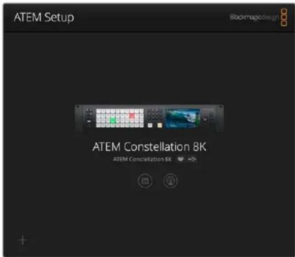
Blackmagic ATEM Setup is used to configure network settings including IP address, plus lets you update your ATEM switcher's internal software. You can also launch ATEM Software Control from the setup utility by clicking on its icon next to the settings icon.
On Mac, all the files needed to run your ATEM switcher will be installed into a folder called Blackmagic ATEM Switchers in the Applications folder.
In the Blackmagic ATEM Switchers folder, you will see ATEM Software Control and Blackmagic ATEM Setup. ATEM Software Control is the software control panel for your switcher, which also allows loading graphics into the switcher media pool, changing settings, mixing audio, recording macros and controlling Blackmagic cameras, including Blackmagic Studio Cameras, Micro Studio Cameras and URSA Broadcast.
Blackmagic ATEM Setup is the setup utility that allows you to browse connected switchers, add additional switchers that are not automatically detected via their IP address, change your switcher IP address, and update the switcher and panel software.
Also included in this folder is the instruction manual and some example graphics. Use the example graphics to explore the internal media pool and keying functionality.
Installing Blackmagic ATEM Software on Windows
It is a good idea to uninstall any previous version of ATEM software present on your Windows PC before installing the latest software.
1 Ensure you have the very latest driver. Visit www.blackmagicdesign.com/support
2 Open the "Blackmagic ATEM Switchers" folder and launch the "Blackmagic ATEM Switchers Installer".
3 The software will now be installed on your system. An alert will appear: "Do you want to allow the following program to install software on this computer?" Click Yes to continue.
4 You will see a dialog bubble saying "found new hardware" and the hardware wizard will appear. Select "install automatically" and the system will find the required Desktop Video drivers. You will then receive another dialog bubble saying "your new hardware is ready for use."
5 Now restart your computer to enable the new software drivers.
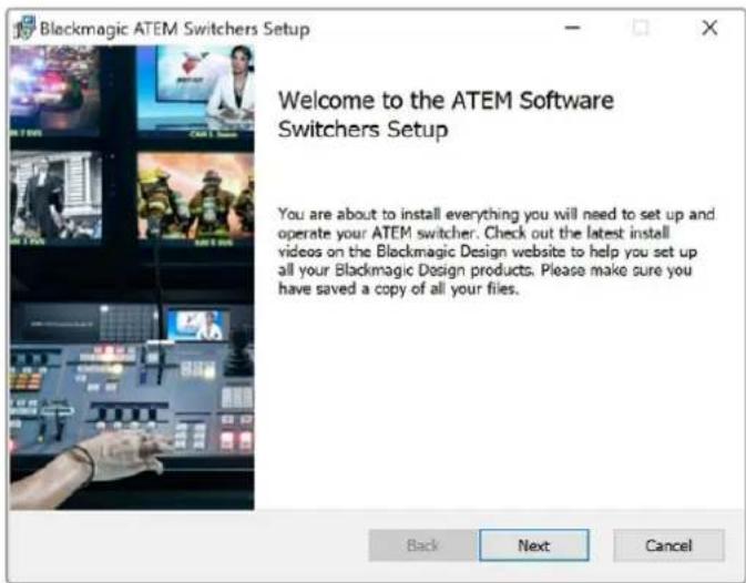
Follow install prompts
Once the computer has restarted, all the ATEM software applications will be installed and can be accessed from Start > Programs > Blackmagic Design.
In the ATEM Switchers folder, you will see ATEM Software Control and Blackmagic ATEM Setup. ATEM Software Control is the software control panel for your switcher, which also allows loading graphics into the switcher media pool, changing settings, mixing audio, recording macros and controlling Blackmagic cameras including Blackmagic Studio Camera, Micro Studio Camera, and URSA Mini.
Blackmagic ATEM Setup is the setup utility that allows you to browse connected switchers, add additional switchers that are not automatically detected via their IP address, change your switcher IP address, and update the switcher and panel software.
Also included in this folder is the instruction manual and some example graphics. Use the example graphics to explore the internal media pool and keying functionality.
Plugging in your Computer
You can plug your computer directly into the ATEM switcher so you can control the switcher, load the media pool with graphics and clips, and change switcher settings.
Connecting your computer is easy and after installing the ATEM Switcher software follow the directions below:
1 Connect an Ethernet cable from the switcher Ethernet port labeled Switcher Control to the Ethernet port of your computer.
TIP If you have a hardware panel installed and already connected to your ATEM, then plug your computer into the second Ethernet port on your hardware panel instead. Now the computer will talk via your panel to the switcher, and both the hardware panel and this software control panel can be operated in parallel.
2 Ensure your ATEM switcher is powered on.
3 Launch ATEM Software Control.
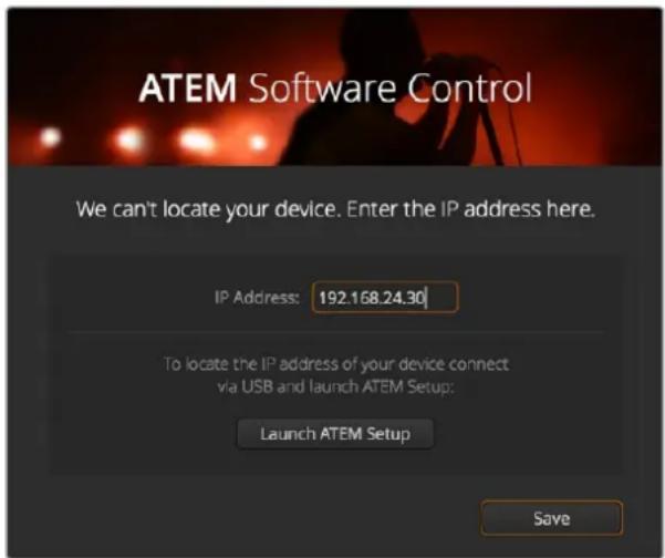
The setup dialog box will help you if you need to manually add your switcher's IP address when launching ATEM Software Control.
When running ATEM Software Control for the first time after installation, you will be prompted by a setup dialog box to set the language for the software, plus choose between 'program/preview' or 'A/B direct' transition control. You can learn more about these transition controls earlier in the 'Getting Started' section, under 'What is an M/E Switcher?' and 'What is an A/B Direct Switcher?'.
After you have made your selection, click 'continue'. ATEM Software Control will remember these settings the next time it is launched. The software will now automatically search for your ATEM switcher. If an earlier version of your switcher's internal software is detected, you will be prompted to update. Simply follow the prompts, or refer to the 'updating the software' section for more information.
After updating, or if the internal software is already up to date, the setup dialog box will disappear and the switcher page will be enabled so you can start using your ATEM switcher immediately!
If the setup dialog box remains visible, you will need to enter your switcher's IP address. The dialog box provides a button to open Blackmagic ATEM Setup where you can quickly locate your ATEM switcher's IP address. Copy the IP address from Blackmagic ATEM Setup, paste it into the dialog box's 'IP address' setting, then click 'save'.
In the rare case your ATEM switcher is still not found, don't be concerned. The solution is likely a network setting on your computer. Changing network settings is fast and will only take a moment.
To change network settings:
1 Open your computer's network settings using the control panel in Windows, or via 'preferences' on Mac. Select the Ethernet connection for your switcher and set it to 'manual'.
2 In your computer's network settings, set the 'IP Address' to 192.168.10.50 and confirm the new setting. If you don't see the switcher software enabled, try changing the last two digits of the new IP address to another number, such as 51, and click 'apply'.
After a brief pause, the setup dialog box should disappear and ATEM Software Control will enable the 'switcher' page with buttons illuminated. You're now ready to start using your ATEM switcher and your setup settings will be remembered the next time you launch ATEM Software Control.
If you're more technically minded and want to connect your ATEM switcher to your existing network, then you will need to change the network settings on your ATEM switcher and control panel. Information on how to do this is available in the next section. You will need to manually set the IP address for the switcher as well as all control panels to match your network IP address range. Your ATEM switcher defaults to a fixed IP address of 192.168.10.240 when shipped and, by using the Blackmagic ATEM Setup, you can customize the IP address for your custom network configuration.
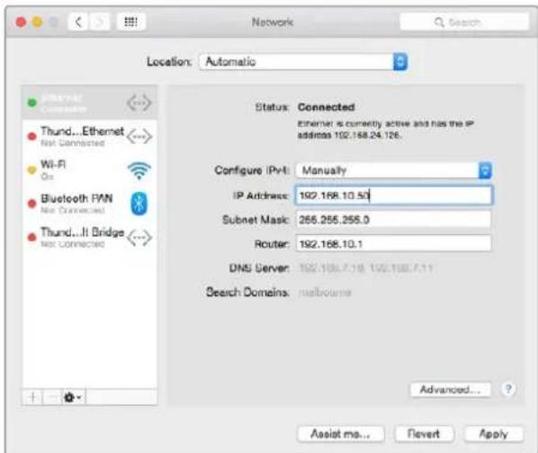
Manually setting the IP address for your Mac.
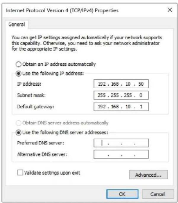
Manually setting the IP address for your Windows computer.
Switcher Settings
Now you have the software control working, you'll need to apply your switcher settings. Click on the gear icon on the lower left side of the interface to open the settings window of the ATEM Software Control.
Set the switcher video standard
You can set the video standard to suit the region in which you are broadcasting, such as 2160p29.97, 1080i59.94, 720p59.94 or 525i59.94 NTSC if you are broadcasting in NTSC based countries. If you are broadcasting in PAL based countries, you can set your video standard to formats such as 1080i50, 720p50 or 625i50 PAL.
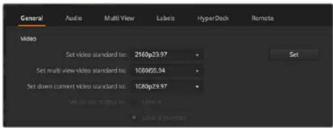
Set Video Standard
If you're working with standard definition video equipment in the widescreen anamorphic 16:9 video format, select 525i59.94 16:9 for anamorphic NTSC or 625i50 16:9 for anamorphic PAL.
Make sure all your cameras and any connected HDMI devices are also set to the same video standard, or they won't be visible on the switcher video inputs. This is generally quite easy, as countries have standards for their HD and Ultra HD broadcasts and all equipment sold in these countries matches this standard or at the very least can be switched between standards. When all video standards are matched, you should see connected devices show up in the multi view video input windows.
Set Audio Preferences
The ‘audio’ tab lets you select which outputs to use for audio monitoring. You can also mute incoming talkback on SDI inputs and outputs prevent a potential feedback loop in the talkback channels.
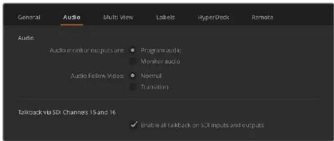
Audio Settings
ATEM Television Studio HD, ATEM Television Studio Pro HD and ATEM Television Studio Pro 4K models also feature mix minus settings on SDI outputs 5 to 8 so you can mute the corresponding input from its program return output. All 10 8K inputs and all 40 HD and Ultra HD inputs of ATEM Constellation 8K are mix minus capable. For more information, refer to the section titled, 'Setting the Audio Output Behavior'.
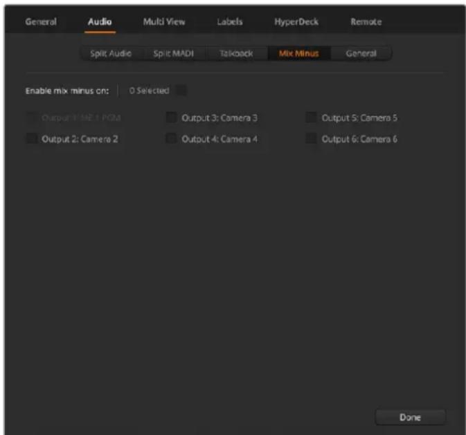
Mix minus settings in the audio tab let you mute the corresponding input from its program return output on some ATEM switcher models
Set and Label Video Input Settings
Different models of ATEM switchers allow some inputs to share connections on the rear panel. For example on the ATEM 1 M/E Production Studio 4K model, input 1 can be switched between HDMI and SDI.
While you're setting inputs, you might also want to change the input labels. These labels appear on the multi view and the hardware panel. There are two labels to change: a long label used in software, and the short label that's limited to 4 digits and used in the broadcast panel.
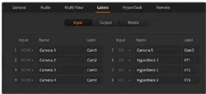
Set Video Inputs and Labels
Customize the Multi View
ATEM switchers have 10 input views in the multi view arranged as 2 large views and 8 small views, and ATEM Constellation 8K has additional options for 4, 7, 13 or 16 input views. This lets you select from a range of external and internal sources to display on these views. Click the menus to select what you want on each view. If you don't have enough cameras on your job to fill all input views, you can select other sources such as media players or color generators. It's extremely flexible and you can also change the multi view layout to suit your preference.
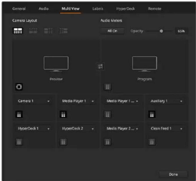
Customize the multi view
If you are using ATEM 6.9 or newer and an Ultra HD model ATEM switcher, you can change the position of the program and preview windows in the multi view. Simply click on the toggle button located between the two windows in the multi view settings.
ATEM Constellation 8K has flexible multi view layout options for 4, 7, 10, 13 or 16 views. These modes let you configure views from up to 16 sources per multi view, which is useful for viewing a large number of sources such as cameras and Hyper Decks at the same time. Because ATEM Constellation 8K has 4 multi views in HD and Ultra HD mode and each multi view displays up to 16 views, you can show up to 64 views at the same time!
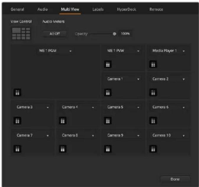
Customize the multi view for ATEM Constellation 8K.
Audio meters can be turned on or off within each source view, or all at once, by clicking on the respective icons in each view or the 'all on' button, respectively.
You can also turn the safe area guides in the preview window on or off by clicking the respective icon.
Connect a HyperDeck
If you are running ATEM 6.8 or newer, you can connect up to four HyperDeck disk recorders to your ATEM switcher. This lets you use a HyperDeck as a high capacity media pool or record your switcher's output. Refer to the 'HyperDeck Control' section in this manual for more information.
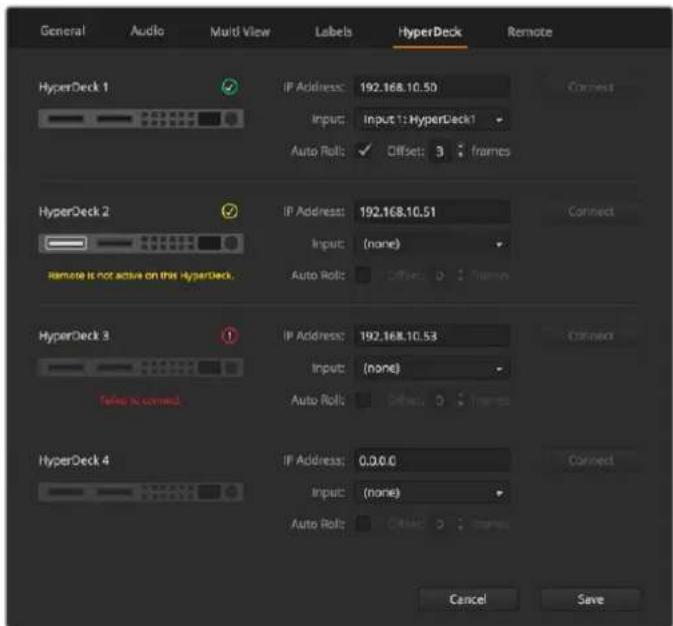
Connect a HyperDeck
Select the Control Panel
You can use ATEM Software Control's M/E 1 Control Panel with any ATEM switcher. The panel is compact enough to fit on smaller displays including on notebooks. If you have an ATEM 2 M/E Production Switcher and a 1920 x 1080 or larger computer display, you can use the full size M/E 2 Control Panel to see the full set of buttons at once. Simply maximise the control panel to full screen, or resize the window until both panels are revealed.
Plugging in Cameras and Other Video Sources
Now you're ready to plug in cameras! All you need to do is connect a cable from the camera video output, either HDMI or SDI, and then connect it to an input on the ATEM switcher.
If you're using ATEM 6.8 or newer, you can even plug in up to 4 Blackmagic HyperDeck Studio model disk recorders and control them using the ATEM software control panel. This is a very powerful feature that effectively gives you an entire videotape department at your fingertips. HyperDecks are connected to your switcher via SDI or HDMI and controlled via Ethernet. For detailed information about how to connect HyperDecks to your ATEM switcher and control them using ATEM Software Control or by an ATEM hardware control panel, refer to the 'HyperDeck control' section of this manual.
Each connector on the switcher has an input label so you can see what camera or source is what input when viewed on the multi view and the control panel. If all your cameras and sources are using the same video standard as set in your switcher, you will see each of them appear as you plug them in.
You don't need to worry about genlock for your cameras and sources, because each input of your ATEM switcher has a full frame resynchronizer. If the ATEM switcher detects that a video source is out of sync, it will automatically enable the frame sync so the input is clean for use. The frame sync function also allows consumer cameras to be connected to your ATEM, and using consumer cameras is a great way to get started because the latest HDMI based consumer HD and Ultra HD cameras are now very affordable, and give quite acceptable HD and Ultra HD. This lets you spend your money on more cameras, and then as you grow, you can start adding professional SDI based cameras.

natural_image
Illustration of a vintage oscilloscope setup with monitor, laptop, and headphones (no text or symbols visible)You can control Blackmagic Studio Cameras and URSA Mini cameras from your ATEM switcher via the SDI return feed
ATEM switchers feature a 'ref in' connection to offer low latency synchronization of feeds between compatible equipment. If you are using an external reference source such as Blackmagic Sync Generator or Blackmagic HyperDeck Extreme 8K HDR, connect the reference signal from your sync source to the 'ref in' BNC connector.
If you're plugging a computer with HDMI compatibility into the HDMI inputs of an ATEM switcher, then be sure that the monitor settings on the computer are set to the correct resolution and frame rate. For example, if you are using 4320p video, then your monitor needs to be set to 4320 x 7680 resolution, and if using Ultra HD 2160p video then set your monitor to 3840 x 2160. For 1080i your monitor should be set to 1920 x 1080. Alternatively, if you are using HD 720p video, then set your monitor to 1280 x 720. NTSC should be set to 720 x 486, and PAL needs to be set to 720 x 576. The frame rates also need to match.
NOTE It's important to know that HDMI cable quality can vary, so we recommend buying good quality cables, and high end video resellers will stock a range of high quality cables. Good quality cables will help eliminate unwanted sparkle or glitches in HDMI video inputs.
If you don't see video on a HDMI video input, even though you have a device connected, then you might want to check if the HDMI device you have connected uses HDCP content protection. This content protection actually encrypts the video data in the HDMI video cable, so the manufacturer does not allow the content to be seen on anything other than a television. You won't be able to see images from these devices. Devices with HDCP content protection include DVD players, and set top boxes.
In general, cameras and computers don't have content protection, so you should not have any problems connecting these devices. Some gaming consoles don't include HDCP content protection, however generally these are only the developer versions of these gaming consoles. Using the analog component input of a Mini Converter Analog to SDI or the analog component input on an ATEM 1 M/E Production switcher to connect devices is a good work around in these situations.
Always be sure you have copyright ownership before using or displaying content publicly.
On 1 M/E, 2 M/E and 4 M/E switcher models you can connect a remote camera head and control it using pan, tilt and zoom controls with the joystick on an ATEM hardware control panel. Refer to the ‘using ATEM hardware panels’ section in this manual for more information on setting up PTZ control.
Plugging in Audio
Your ATEM switcher includes a built in audio mixer which allows the use of embedded HDMI and SDI audio from your cameras as well as external audio from the dedicated analog audio or MADI inputs. Depending on the ATEM switcher you are using, these may be XLR, 1/4" jacks, RCA or MADI BNC inputs. These audio inputs can be used for other audio sources such as camera microphones and pre-recorded audio.
See ‘using audio’ for more on connecting additional audio sources.
Connecting to a Network
If you want to connect your ATEM switcher to a larger Ethernet network, then you will most likely need to change the network settings on your ATEM switcher. Most people simply plug their computer and control panel direct to the switcher, however in some situations it can be very powerful to connect via your network!
Your ATEM ships from the factory with settings to allow hardware control panels to simply be connected directly with an Ethernet cable. Your ATEM supports full Ethernet IP protocols so you can place your switcher and panel on your network or anywhere on the planet using the internet.
It's worth noting that if you use your ATEM on a network, then you're also increasing the complexity of the connection between your control panel and the switcher, so there is possibly a greater chance of something going wrong. However, ATEM can be used when plugged into a switch, and even via most VPNs and over the internet.
natural_image
Illustration of a radio tower emitting signal waves against a sky background (no text or symbols)To allow communication over Ethernet, the IP addresses of the switcher, broadcast panel and any computer running ATEM Software Control needs to be configured correctly. The IP address used for each device will depend on the IP address range of the network you're plugging into.
The ATEM switcher always needs a fixed IP address so control panels have a stable location to connect to. This means you need to find a free fixed IP address in the range of your network that you can use.
The control panels can be set to DHCP or fixed IP addresses. Generally when used on a network, the control panel would be selected to DHCP, so it is automatically assigned an IP address when connected to the network.
For all devices to communicate, they must share the same IP address subnet, which typically means the first 3 fields in the IP address need to be the same. Each device must also use a unique IP address.
Please remember to set all devices to the correct IP address so they can all communicate. You will need to set the IP address of the ATEM switcher via USB using Blackmagic ATEM Setup. You will need to set the DHCP or fixed IP mode on the ATEM Broadcast Panel and if using a fixed IP address on the panel, set the IP address on the panel. You will also need to set the panel's 'switcher address' to the new IP address you have just set for the switcher.
Lastly, you need to ensure your computer is connected and working on your network. Then when you launch the ATEM Software Control application, you will be prompted automatically to enter in an IP address for the switcher if ATEM Software Control cannot communicate with the ATEM switcher. Use the IP address you just entered for the switcher. Then the ATEM Software Control can find the switcher and communicate.
Changing the Switcher Network Settings
The switcher network settings are changed using the Blackmagic ATEM Setup via USB. Please follow the steps below:
1 Connect the switcher via USB, to the computer running the setup utility software.
2 Launch Blackmagic ATEM Setup and select your switcher or broadcast panel.
3 The switcher's current IP address, subnet mask and gateway settings will be displayed in 'configure' window. If you only want to check the IP address and not change it, you can simply quit the setup utility by clicking 'cancel'.
4 To change the IP address or any other settings, simply edit the numbers and then click 'save'.
5 A dialog box will prompt you to power cycle your ATEM switcher. Turn the switcher's power off, turn it back on and then close the dialog box.
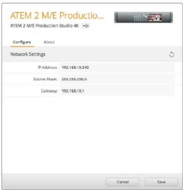
Change network setting using the 'configure' tab in Blackmagic ATEM Setup.
Understanding ATEM Hardware Panel Network Settings
The hardware panel's network settings are configured from the network setup menu in the hardware panel's system control. Along with its own IP address, the hardware panel also needs to be configured with the network location of the switcher, so that communication between the two devices can be established over the Ethernet connection. If the hardware panel's network settings are correctly configured, you will see the panel light up and buttons turn on so you can control the switcher.
If the hardware panel is displaying a message looking for the switcher, then you will need to set the hardware panel's network settings so that the panel and switcher share the same subnet, and the network location to which the hardware panel is trying to connect, matches the switcher's IP address.
Setting the Switcher IP Location
To set the network location of the switcher on the hardware panel, so the panel can find the switcher and communicate, follow these steps:
Changing the IP location on an ATEM Broadcast panel
1 When there is no communication with the switcher, the NETWRK SETUP menu will appear on the broadcast panel system control. Select the NETWRK SETUP menu button.
2 Select the SWITCHR IP menu button and use the knobs or the numeric keypad to edit each field as required.
3 When a field is changed, SAVE and REVERT menu buttons become available. Select SAVE to save the changed IP address, or REVERT to ignore the changes and revert to the currently stored IP address.
4 If the switcher IP address setting is changed, selecting SAVE will apply the changes and the broadcast panel will attempt to establish communication with the switcher using the new IP address.
This does not change the IP address of the switcher itself. It just changes where the control panel is looking to find the switcher. If the control panel cannot find the switcher, then you might need to check the switcher to see if it's been set correctly. To change the IP address of the switcher, connect the switcher via USB to a computer and run Blackmagic ATEM Setup as described previously in this manual.
Home Menu
ATEM 1 M/E Production Switcher
Control Panel Connected OK
Panel IP Address: 192.168.10.10
Connecting to 192.168.10.240...
Control Panel Not Connected
Changing the IP location on ATEM 1 M/E Advanced Panel
When there is no communication with the switcher, the LCD will say 'connecting' and notify you of the IP address it is searching for. If the panel can't find the switcher, the connection will time out and a notification will ask you to check the IP address. Press the 'network' soft button above the LCD to open the network settings.
2 In the network settings, press the right arrow in the system control buttons next to the LCD to move to the 'switcher IP address' setting.
3 Now use the corresponding LCD soft control knobs to set the correct IP address for your switcher.
4 Press the 'save changes' soft button to confirm the setting.
Your panel will now connect with your switcher.
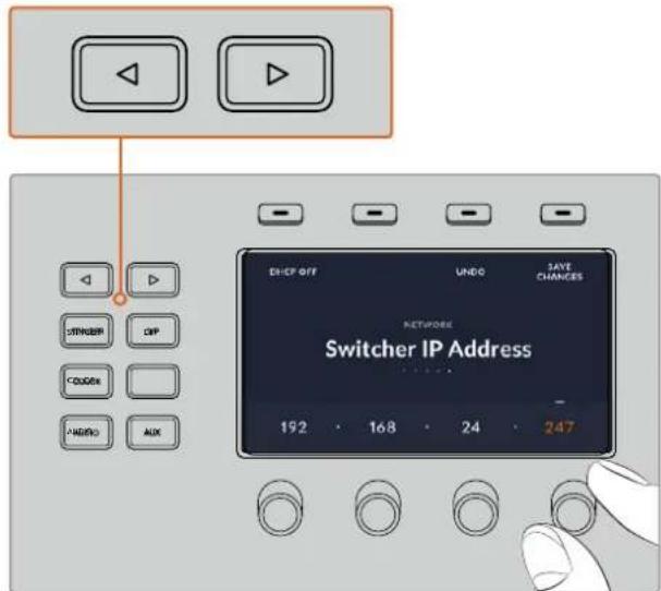
On the ATEM 1M/E Advanced Panel, press the 'network' LCD soft button to open the network settings on the LCD, then use the system control arrow buttons to navigate to the switcher IP address setting. Use the soft controls to set the network IP address for your switcher, and don't forget to save the changes.
NOTE Changing the switcher IP address on your panel does not change the IP address of the switcher itself. It just changes where the control panel is looking to find the switcher. If the control panel cannot find the switcher, then you might need to check the switcher to see if it's been set correctly. To change the IP address of the switcher, connect the switcher via USB to a computer and run Blackmagic ATEM Setup as described previously in this manual.
Changing the Hardware Panel Network Settings
Because the hardware panel is also on the network and communicating with the switcher, it also has network settings so it can connect to the network. These settings are different to the switcher IP address, which is just where the panel is looking to find the switcher. The panel network settings can be changed by following the steps below:
Changing Network Settings on ATEM Broadcast Panels
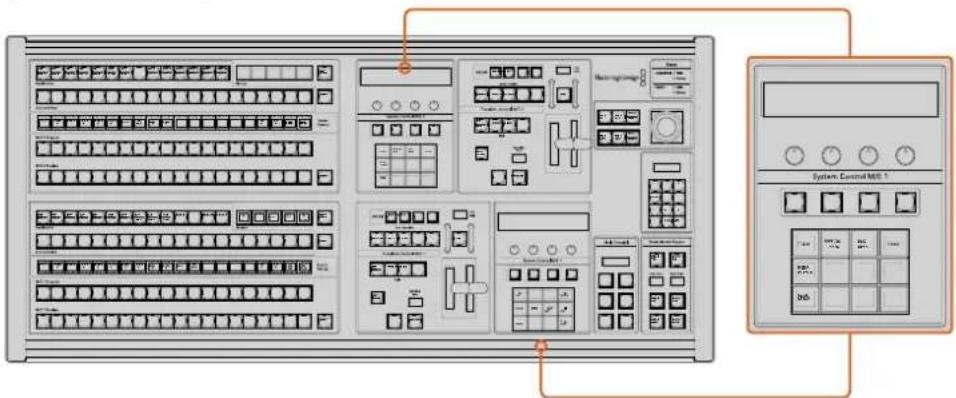
Change Network Settings from the System Control
1 On the broadcast panel system control menus, select the NETWRK SETUP menu button.
If the broadcast panel has already established connection to the switcher, you can access the NETWRK SETUP menu from the HOME menu by pressing the SHIFT and CUT/FILL buttons simultaneously on the ATEM 1 M/E Broadcast Panel, or the SHIFT and DEST SHIFT buttons in the M/E 1 block of the ATEM 2 M/E Broadcast Panel. This will reveal the NETWRK SETUP menu button so you can select the network settings.
2 The broadcast panel's current IP address, net mask and gateway information is displayed.
3 The next step is to decide if you want the panel to use a fixed IP address or to be automatically assigned an IP address from a DHCP server. Select PANEL DHCP to set this using the soft keys on the main display.
If you're connecting direct to a switcher without a network, then you won't have a DHCP server to assign an IP address automatically, so you will want to select fixed. ATEM Broadcast Panels are delivered with a fixed IP address set to 192.168.10.10, for a direct connection.
However, if your network has lots of computers that automatically assign IP addresses via DHCP, then you can also select DHCP on the panel so the panel can get its network information automatically. This is possible on the panel, and it's only the switcher itself that always requires a fixed IP, as the switcher needs to be found by the control panels at a known fixed address on your network.
If you select DHCP, your network settings will be complete because the panel network settings will be obtained from the network automatically.
4 If you have elected to use a fixed IP address, you now need to set this IP address by selecting the PANEL IP menu button and use the knobs or the numeric keypad to edit each field as required. Changing this IP address may cause the panel to lose communication.
5 If the subnet mask and gateway address need to be set, then select the relevant buttons on the system control buttons to set and use knobs or the numeric keypad to edit.
6 When any settings have been changed, SAVE and REVERT menu buttons will become available. Select SAVE to save the changes to the new network settings, or REVERT to ignore the changes and revert to the current network settings.
Changing Network Settings on ATEM 1 M/E Advanced Panel
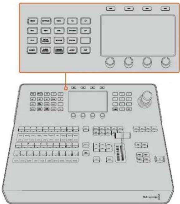
Change network settings using the system control buttons and LCD soft controls
1 Press the 'home' button in the system control buttons to open the LCD home menu.
2 In the home menu, press the 'network' soft button to open the network settings.
3 The next step is to decide if you want the panel to use a fixed IP address or to be automatically assigned an IP address from a DHCP server. Set DHCP on or off by pressing the corresponding DHCP ON/OFF soft button.
NOTE If you're connecting direct to a switcher without a network, then you won't have a DHCP server to assign an IP address automatically, so you will want to select 'DHCP off'. ATEM 1 M/E Advanced Panel is delivered with a fixed IP address set to 192.168.10.60 for a direct connection.
However, if your network has lots of computers that automatically assign IP addresses via DHCP, then you can also select 'DHCP on' so the panel can get its network information automatically. This is possible on the panel, and it's only the switcher itself that always requires a fixed IP, as the switcher needs to be found by the control panels at a known fixed address on your network.
If you select 'DHCP on', your network settings will be complete because the panel network settings will be obtained from the network automatically.
4 If you have elected to use a fixed IP address, you now need to set this IP address by adjusting the corresponding soft control knobs for each field of the IP address. You can also use the numeric keypad. Changing this IP address may cause the panel to lose communication.
5 If the subnet mask and gateway address need to be set, then press the right arrow button in the system control buttons to progress through each setting menu, and use the knobs or the numeric keypad to edit. If at any time you want to cancel the changes, press 'undo'.
6 When you are happy with your settings, press the 'save changes' soft button to confirm
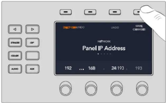
When you are happy with your network settings, press the 'save changes' button to confirm them
Setup Workflow with ATEM Constellation 8K
If you are using an ATEM Constellation 8K, your switcher has a built in control panel. This means when setting up your production, you can check all your sources and control the switcher directly from the front panel. This is a practical way to establish everything is set up correctly from the switcher, being the heart of the production chain.
This section provides a basic example of how to use your switcher's front panel when setting up your production.
1 Confirm all your sources are working. These may be cameras or other sources, for example graphics from a computer, or video clips from a HyperDeck.
You can check all your sources by switching them to the program output. To do this, press an input button. It will illuminate green, indicating it is switched to the preview output. Pressing the 'cut' or 'auto' button will cut or transition the preview source to the program output. This is also a good opportunity to test any custom transitions.
2 Once you have confirmed that all sources are present, check that each of them are sending the format and frame rate your switcher is set to. If that isn't always possible, your switcher will automatically convert the inputs. However, it's worth mentioning that 720p and 1080i is not up converted to 8K.
3 The next step is to check that talkback is working properly.
On ATEM Constellation 8K you have the option to communicate with both production and engineering teams. Both have a unique talkback button on the front panel. Press and hold the talkback buttons to communicate. If you want to lock the mic open so it stays on indefinitely, double press to enable 'lock to talk' mode. Double press again to return to 'press to talk' mode.
If you can communicate successfully with your camera operators and engineering personnel, you can then adjust the headset monitoring levels to your preference. This is achieved by pressing each talkback channel to activate it, for example 'Prod Talk' and then pressing the channel volume up and down arrows to adjust its monitoring level. This lets you mix the levels so you can comfortably hear exactly what you need to hear.
4 After you have confirmed talkback functionality, it's a good idea to check that tally is working on all cameras.
To do this, press an input source button to switch it to the preview output. This will engage the green tally light on supported Blackmagic Design cameras. Pressing the 'cut' or 'auto' button will cut or transition the source to the program master output and the camera's tally light will illuminate red indicating the camera is on air.
If you are not seeing the tally lights illuminate, check the camera numbers are set correctly according to the switcher's corresponding input number. This can be set in the camera's menu settings.
5 With your sources set up and talkback and tally working, you're all set! Now you can press the 'call' button. This sends a signal to all Blackmagic Design cameras via their SDI return feeds, simultaneously activating their tally lights. It's a great way to engage the operators' attention, letting them know you are about to go to air!
Updating the Software
How to update the ATEM Software
From time to time Blackmagic Design will release new software for your ATEM switcher and hardware panel, with new features, bug fixes, and increased compatibility with third party software and video devices.
To update your ATEM switcher with new software, you need to use Blackmagic ATEM Setup to connect to the ATEM switcher and broadcast panels. Blackmagic ATEM Setup will check your switcher's internal software and will ask if you wish to update if you have a newer version installed on your computer.
Always update all your equipment at the same time so it's all running the same version of software.
To perform an update, you can directly connect your ATEM switcher or broadcast panel to the computer via USB.
Alternatively, if your switcher is running ATEM software 6.6 or later and you already have your switcher connected to your computer via Ethernet, you can simply update via the Ethernet connection.
First, download the latest Blackmagic ATEM Switcher software and install it on your Mac or PC using the instructions listed previously in the Installing Software section of this manual. Once installed, the new software for your ATEM switcher and broadcast panel will be included in the ATEM setup utility.
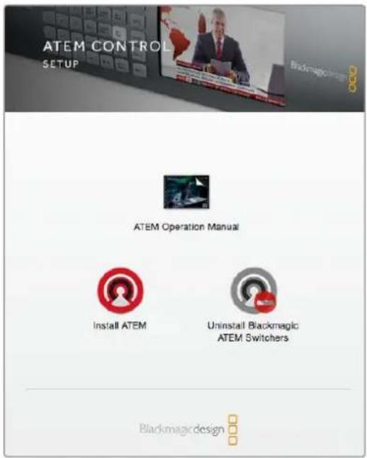
ATEM Software Installer
Updating the Switcher Software
1 Connect the switcher via the USB port.
If your switcher is running ATEM software 6.6 or later and you already have your switcher connected to your computer via Ethernet, you can update via the Ethernet connection.
When upgrading software via USB, make sure the switcher is the only ATEM device connected via USB to the computer running the setup utility software. If more than one ATEM device is connected, the switcher may not be recognized.
2 Launch Blackmagic ATEM Setup.
3 If the switcher software requires updating, you will be prompted by a window asking if you would like to update the software. Click 'update' to initiate the update process, which may take a few minutes. It's important you don't unplug the power from the switcher during the software update.
4 Once the software update is complete, a window will prompt you to cycle power on the switcher. Turn your switcher off and on, then 'close' the dialog box.
Updating an ATEM Hardware Panel
1 Connect the ATEM hardware panel to your computer via USB. If your broadcast panel is running ATEM software 6.6 or later and you already have your panel connected to your computer via Ethernet, you can update via the Ethernet connection.
NOTE When upgrading software via USB, make sure the broadcast panel is the only ATEM device connected via USB to the computer running the setup utility software. If more than one ATEM device is connected, the panel may not be recognized.
2 Launch Blackmagic ATEM Setup.
3 If the panel requires updating, you will be prompted by a window asking if you would like to update the software. Click 'update' to initiate the update process. It's important you don't unplug the power from the panel during the software update.
4 Once the software update is complete, a window will prompt you to power cycle your hardware panel. Turn your panel off and on, then click 'close' in the dialog box. If you are updating an ATEM 1 M/E Advanced Panel, the panel will power cycle automatically.
Updating via Ethernet
Updating your ATEM switcher or broadcast panel via Ethernet is generally faster and easier, however there are some instances, such as those below, where it may not be possible and you will need to update via USB:
- Updating the internal software for the first time.
- Your ATEM network settings are already configured to work straight away, however if your are connecting to a network with other video equipment, there may be potential IP address conflicts which may prevent communication between your computer and your switcher. Network settings can only be set via USB.
- Running internal software earlier than version 6.6.
- Rolling the internal software back to a version earlier than 6.6.
Connecting Video Outputs
Video Outputs
There are multiple video outputs on your ATEM switcher which can be used to connect to a wide range of video equipment. ATEM Constellation 8K supports HD, Ultra HD and 8K. ATEM Production Studio 4K and Broadcast Studio 4K models include Ultra HD, HD and SD via SDI. HDMI is also supported on ATEM Production Studio 4K models. Descriptions of each output connection are listed in this section.
It's important to note that on ATEM Constellation 8K, the outputs are not dedicated with specific labels like they are on other ATEM switchers and that's because you can route any source to them. For example, on an 8K production you may want the program output on output 1, a clean feed on output 2 and route camera sources to the other 4 outputs for ISO recording. This gives you more flexibility to switch any source to any output fast.
Plug in Ultra HD outputs via the 24 12G-SDI connectors on the rear panel. When the switcher has 4320p set as the video format, the 24 connectors are automatically configured as 6 quad link outputs.
SDI Program Output
This SDI output switches between Ultra HD, HD and SD. It outputs the main program video output of your ATEM switcher and can be connected to any SDI based video device. The audio on this output can use embedded HDMI and SDI audio from your cameras as well as external audio via the switcher XLR inputs. ATEM Production Switcher models include a breakout cable for external audio.
HDMI Program Output
Similar to the SDI program output, this output switches between Ultra HD, HD and SD. It outputs the main program video output of the switcher and can be connected to televisions, video projectors or even Blackmagic Design's H.264 Encoder or HyperDeck disk recorders. The audio on this output can use embedded HDMI and SDI audio from your cameras as well as external audio via the switcher XLR inputs.
Multi View SDI and HDMI Output
The multi view outputs on all ATEM switchers are HD except for ATEM 4 M/E Broadcast Studio 4K, which are HD or Ultra HD, and ATEM Constellation 8K, which are HD, Ultra HD or 8K. You can choose from a selection of multi view output formats and frame rates. This feature increases compatibility with a wider range of monitors, plus you can output your multi view in Ultra HD even if you are working in regular HD. Refer to the 'using ATEM Software Control' chapter, multi view settings section for more information.
Some models of ATEM switchers include a single multi view, while bigger models include 2 independent multi views so you can monitor more switcher sources. Each multi view includes 8 video input views, with preview and program views. ATEM Constellation 8K has four multi view outputs for HD and Ultra HD viewing and one 8K multi view when the switcher is in 8K mode.
Tally is included with red for sources on air, and green for preview. You can connect this output to televisions and computer monitors with SDI or HDMI connections.
Down Converted SDI Program Output
Many ATEM 4 M/E Broadcast Studio 4K and ATEM 2 M/E Production Studio 4K models have a dedicated HD-SDI program output.
Auxiliary SDI Outputs
ATEM switchers have auxiliary SDI connections that output the same video format in use. The number of auxiliary outputs vary between models:
- ATEM Production Studio 4K has 1 auxiliary output
• ATEM 1 M/E Production Studio 4K has 3 auxiliary outputs
• ATEM 2 M/E Production Studio 4K has 6 auxiliary outputs - ATEM 4 M/E Broadcast Studio 4K has 6 auxiliary outputs
Auxiliary outputs can use any internal and external video sources. For example, program feeds if you need more program outputs, or clean feeds without down stream keying, or even specific video inputs. Aux outputs are perfect for driving video screens on stage, or feeds where you can independently control what the viewers see. Aux outputs switch cleanly and can be used as cut only switchers independent of the main program outputs. The audio on these outputs is embedded SDI program audio.
It's important to note that all outputs on ATEM Constellation 8K can have any source routed to them, which gives you the flexibility to use any output like it's an aux output.
Preview SDI Output
On switchers with a preview output, this shows the source selected on the preview bus on the switcher, as well as preview transitions. This output is perfect when you want to use a full resolution preview monitor. The audio on this output is embedded SDI program audio.
M/E Output
ATEM 2 M/E Production Studio 4K and ATEM 4 M/E Broadcast Studio 4K have a dedicated SDI preview output for M/E 1, as well as HD and Ultra HD SDI program outputs for M/Es 1 and 2. These can be used as additional preview or program outputs for mix effects blocks 1 and 2.
ATEM 4 M/E Broadcast Studio 4K has 4 M/Es. M/E 3 and M/E 4 are typically routed back through M/E 1 or 2 to create complex layered scenes. You can, also output a feed from M/E 3 or M/E 4 by assigning them to auxiliary SDI outputs.
NOTE SDI outputs for ATEM Constellation 8K can have any source routed to them.
For maximum flexibility, you can route any internal or external video source to any of its 24 HD or Ultra HD outputs, or any of its six 8K outputs. Video sources can include program, clean feed, preview, M/E output, as well as cameras and other external equipment.
8K SDI inputs and outputs on ATEM Constellation 8K use the two sample interleave technique, also known as 2SI. It is important to connect your quad link SDI cables in the correct order.
Audio for ATEM Constellation 8K outputs is embedded in the SDI stream, or you can route it to the analog audio out channels or MADI outputs.
Using the ATEM Constellation 8K Front Panel
ATEM Constellation 8K includes a fully functioning front panel that lets you operate the switcher from the front panel. While you can easily use the front panel for live switching, its intended purpose is for initially testing your production setup before going to air. For example, the control panel lets you quickly test keyers, switch sources and generally confirm everything is working fine before settling into the main production. This is why we added a lock button so once you are happy that everything is working fine, you can lock the panel and make sure there are no accidental changes to air.
This section shows you how to use all the features on your switcher's front panel for setup and testing.
Performing a Transition
When checking your setup, the first step you may want to try is to perform a transition. The group of 40 large buttons represents the inputs into the switcher. All 40 buttons are active in HD and Ultra HD mode and the first 10 buttons control the 10 quad link 8K inputs in 8K mode. When you first turn on the switcher, you will see input 1 is the button illuminated red. This means that input 1 is on air and if you have a video source connected to input 1 it will appear on the program output.
Unlike a standard program/preview switcher control panel, these buttons on ATEM Constellation 8K serve as both preview and program source buttons and will illuminate green and red to indicate which source. This section shows how to use the buttons to switch content to the preview and program outputs.
In this example, we have input 1 on air and we want to transition to input 4.

In program/preview mode with input 1 on air and input 4 on preview
To perform a transition:
1 Select the next source by pressing button 4. The button will now illuminate green to show it's selected on the preview bus.
2 Press the cut or auto buttons.
If you press cut, button 4 will now illuminate red as it's on air. Input 4 will also be switched to the program output. If you select auto, then the currently selected transition will be triggered. While the transition is occurring, you will see both buttons illuminated red because both sources are on air during the transition.
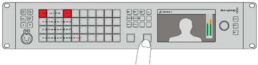
Press the 'auto' button to perform an auto transition.
That's all there is to it! If you would like to change the transition type, then you can do this in the LCD menus or the four dedicated transition selection buttons on the front panel. You can choose from Mix, Dip, Wipe and DVE transitions with the touch of a button.
To change the transition type:
1 Press the menu button to display the menus.
2 Scroll with the knob through the menus to the 'transition' menu.
3 Press the set button and you will see the transition menu page will be selected.
4 Scroll down the list of items in the transition menu until you get to the transition item.
5 Press the set button and scroll through the list of options. Let's select the DVE transition.
6 Press 'set' to select it. You can press the 'menu' button to back out of the menus back to the main video preview screen.
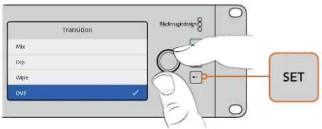
Use the LCD menu to select the transition type and you can also set the transition duration in the transition settings.
While in the menu, you can press the 'auto' button to try the different types of transitions available to you. Each one of the transition types listed in the LCD menus can also be selected in ATEM Software Control or a hardware control panel if you have one.
As well as the group of main input buttons, the front panel has other sources labeled 'mp1' and 'mp2'. These are media player 1 and media player 2. If you have graphics in your switcher, such as a graphic or title slide, then you can select the media players as sources and then cut or transition to them. ATEM Constellation 8K has one media player in 8K mode and four media players in HD and Ultra HD mode.
Selecting Other Sources
You can select other sources in the switcher that are not on the front panel from the LCD menus.
To select an alternative program source:
1 Press the menu button to display the menus.
2 Scroll with the knob through the menus to the 'program source' menu.
3 Press the 'set' button and you will see the program source menu page will be selected.
4 Scroll down the list of sources in the 'program source' menu until you get to the one you want. In this example, let's select color bars.
5 Press 'set' to select it.
6 Press the menu button to back out of the menus back to the video preview screen.
You will see color bars appear on the program output and notice that the 'bars' button on the front panel is illuminated red. If you have a source on the front panel selected on preview, you will still see that button illuminated green. You can press cut or auto to transition between the color bars and the preview source.
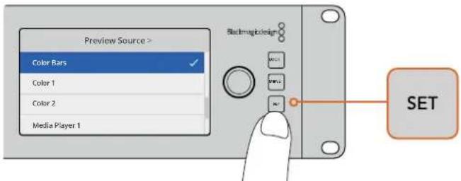
A safe way to preview sources before switching them to air is to use the LCD menu to select sources to the preview output and monitor them on the multi view
Changing to Cut Bus Switching
By default, the control panel works in program/preview mode, which is more like a traditional switcher and means changing sources is a two step process where you select the next source on the preview bus and then select cut or auto. However, in many cases you might like to have the switch to the new source happen immediately when you select it. This mode is called cut bus switching and you can change the mode in the LCD menus.
To change to cut bus mode:
1 Press the menu button to display the menus.
2 Scroll with the knob through the menus to the 'Settings' menu.
3 Press the set button and you will see the settings menu page will be selected.
4 Scroll down the list to the mode menu and select it by pressing the set button.
5 Scroll to the cut bus mode and select it by pressing set.
6 Press the menu button to back out of the menus back to the video preview screen.
Now the front panel will have changed how it works and switching is performed the instant you select a source. For example, try selecting a different source using the main input buttons and you can see that it's immediately selected and the button is illuminated red. You will notice that there is no green button highlighted now and that's because there is no preview bus to select the source as the source is simply selected the moment you push the button and it's on air instantly. That's why all buttons are now illuminated red.
However, there is another change to the front panel in cut bus mode and that's the behavior of the cut and auto buttons. Now the inputs are selected the instant you press them, the cut and auto buttons don't trigger the transition anymore. What they are now used for is to select the type of transition you want when you press the input buttons.
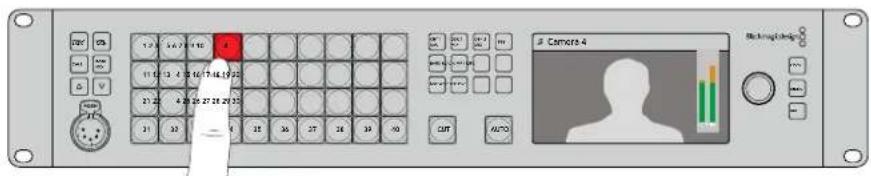
In cut bus mode, any input button you press switches directly to the program output
For example if you want cuts when you select sources, then select the cut button. It will be illuminated and now when you select sources you will see a cut. If you want to do transitions now, then press the auto button. It will illuminate and now when you select sources, you will see that each transition will use your currently selected transition. Use the same process as shown in the previous examples to select the type of transition you want in the LCD menus.
In Case of Strange Behavior!
It's important to note that anything you change on the front panel buttons or in the LCD menus here will also be reflected on the software and hardware panel. What this means is if the front panel does not behave in a normal way and seems to be doing strange things that are unexpected, then it could be that another user has selected a mode that you cannot easily see on the front panel. For example, another user could have a keyer selected and no background, so when you press the auto button you are actually selecting a keyer. If you see this happen, it's a good idea to check the LCD menus or use the software control panel to clear these settings back to normal.
This is very important if someone selects a specific switcher feature and then saves the switcher state! It could mean you turn on the switcher and the front panel does not do what you expect!
Audio Levels
The function of the knob on the front panel is primarily for audio level adjustment, although it is used for menu selection when you are in the LCD menus. Normally it's used for audio level control and you can tell what it's controlling by looking at the LCD. The label on the LCD will tell you what the knob is adjusting.
Normally, the LCD has the label 'master' and this means the knob is adjusting the main audio mixer master output. Adjusting the knob will lower the whole program audio levels and you can see the effect on the main audio meters in the LCD that are superimposed on the video preview.
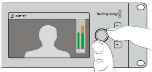
Use the knob to adjust the master audio level and you can see the effect on the main audio meters in the LCD
If you want to adjust the audio for each of the SDI inputs, you can view and adjust the audio levels individually through the menus on the LCD. This is a useful way to identify when the main audio level is too high because single input is too high level. In this case you don't want to adjust the master audio level because all the other inputs will now become too low. You really want to select the input audio level and adjust just that single audio level.
To adjust an input audio level, for example on input 4:
1 Select the input 4 button. This is easier when using program/preview mode as you can just select it on the preview source.
2 The label on LCD will change to that input, for example input 4, to show you're adjusting the level for that specific input.
3 Adjust the knob and you will see the audio meter on the LCD will reduce in level.
If this input is on air, the master audio output will be reduced because this input is being lowered in level.
To go back to the master audio level:
1 Press the set button on the right side of the control panel and it will go back to master immediately. If you don't press 'set', the front panel will automatically switch itself back to master after a few moments.
2 Now adjusting the knob will be adjusting the master audio output and the LCD has master displayed.
This is a quick way to test audio channels when you setup your ATEM Constellation 8K. For fine control of individual audio channel parameters during production, we recommend you use ATEM Software Control.
Fading the Downstream Key 1
You can trigger the downstream key 1 from the front panel by using the DSK 1 MIX button. This can be useful when you have a logo or bug and you want to bring it on and off again regularly. For example you could have a 'live' logo that you want to fade on from time to time. You can set up the logo in the downstream key 1 and then use the DSK 1 MIX button to bring it on and off air. The duration of the transition when pressing the button will be set in the downstream key LCD menu, or on a control panel.
You can feed a keyer with an input or a media player. This can be set up in the LCD menus or on a control panel. If your switcher is new then you can use the software control panel to load the media pool with some graphics or logos so you have sources to use.
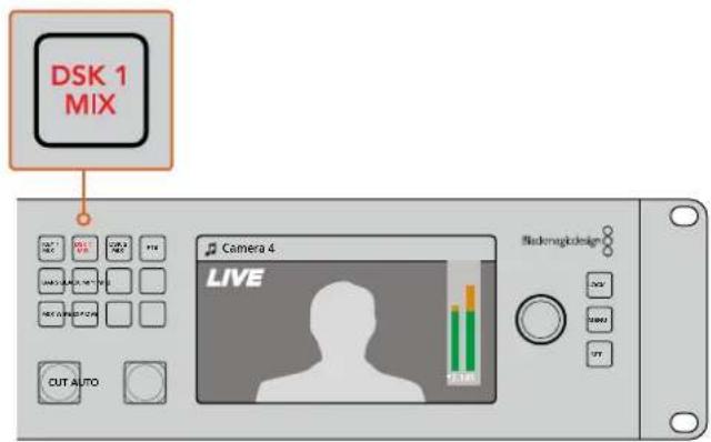
Press the DSK 1 MIX button to fade the downstream key 1 on and off air
Fade to Black
When you start or finish a program, you want to be able to fade to black without worrying about leaving a logo on the screen by accident. Your ATEM switcher has a lot of powerful features and lots of layers that you can enable for transitions. What this means is you could have a complex setup on the switcher with many layers but you really just want a single button to start your program. This is what the FTB or fade to black button does.
If you press the FTB button, the whole program output of the switcher will fade to black. The button will flash to indicate to you that it's active. You can set the duration for the fade to black transition in the LCD menu or on a software or hardware control panel.
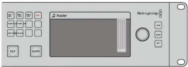
Press the fade to black or FTB button to perform a fade to black on the whole program output, including any graphics or keyers that may be in use
Using the Lock Button
The lock button prevents accidental switching and changes to settings for transitions and media players. When the front panel is locked, the 'lock' button glows a dim red and if a button is pressed it is ignored and the 'lock' button flashes bright red. The 'lock' button doesn't affect the LCD menus or the comms buttons such as 'prod talk' and 'eng talk'.
To unlock the front panel, press and hold the 'lock' button for one second.
To lock the front panel, press and hold the 'lock' button for two seconds.
TIP It's a good practice to lock the front panel of ATEM Constellation 8K while it's on air to prevent accidental switching.
Using the LCD Menus
The LCD menus make almost the entire operation of the switcher available. In the examples in this section, we used the menus and it's a good idea to explore the menus to see what's available. If you have used the software control panel on an ATEM switcher in the past, then you will see that each menu is like a palette on the software control panel and each palette on the software control panel has a menu page on the LCD. There are a few extra LCD menus for configuring SDI outputs and the audio mixer and there is also a settings page for setting up your ATEM Constellation 8K.
To use the menus:
1 Press the 'menu' button to display the menus.
2 Scroll with the knob through the menus to the menu you want.
3 Press the 'set' button and you will see the menu page will be selected to use.
4 Scroll down the list to the specific menu setting you want to change.
5 Select it by pressing the set button.
6 Scroll through the list of options for this menu item.
7 Press set when you want to make the desired setting active.
8 Press menu a few times to go back to the main video preview screen.
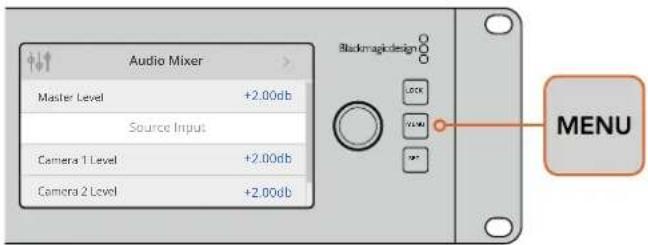
Press the menu button to enter the LCD menu.
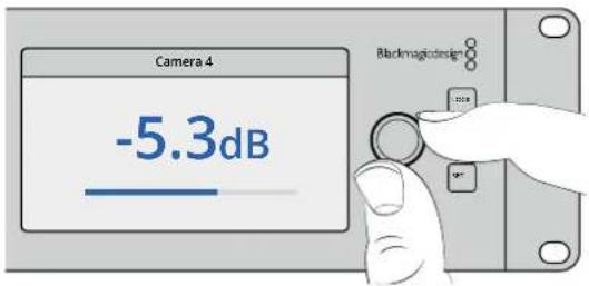
Use the knob to navigate through the settings and make adjustments, for example selecting the audio for input 4 and adjusting the audio level
Using Talkback
ATEM Constellation 8K features push to talk 'prod talk' and 'eng talk' buttons so you can converse with production and engineering teams. Plug an intercom headset equipped with a microphone into the 5 pin XLR socket on the front panel. If you double press one or both of the 'prod talk' or 'eng talk' buttons, the mic stays on and the button illuminates white until you double press the button again.
Next, mix the levels in your headphones for production talkback, engineering talkback and program mix using ATEM Software Control or the front panel. The selected button is lit red, meaning you can adjust its level with the up and down buttons.
The back panel of ATEM Constellation 8K has a 'talkback' connector for for routing engineering talkback and production talkback. For information on how to make your own talkback adapter cable, see the 'Talkback Pin Connections' section.
The Call Button
Holding down the 'call' button will flash the tally light on all connected cameras. This is a helpful way of seeking the camera operators' attention, or to let your operators know you are about to go live.
NOTE ATEM Constellation 8K's front control panel can be used to operate almost all of your switchers features, so it can serve you well as an alternative control panel in the event of an emergency.
Using ATEM Software Control
The ATEM Software Control is included with your ATEM switcher, and allows you to control your switcher in a similar way to a full hardware control panel. However instead of menu buttons, it uses a range of palettes on the right side that shows you all processing features of your production switcher and allows settings to be easily made.
natural_image
Red circular icon with concentric rings and a central white human silhouette (no text or symbols)You can also use the ATEM Software Control to configure your switcher settings as well as upload graphics and manage the media pool.
Preference Settings
The preferences settings are arranged as ‘general’ preferences and ‘mapping’ preferences. The general preferences contain network settings, transition control and language selection options.
General Preferences
ATEM Software Control can be set to display in English, German, Spanish, French, Italian, Japanese, Korean, Portuguese, Russian, Turkish and simplified Chinese languages.
When running ATEM Software Control for the first time after installation, a setup dialog box will prompt you to set the language for the software, but you can change the language of the software at any time.
To change the language:
1 Go to the menu bar at the top of your screen, select 'ATEM Software Control' and open the 'preferences'.
2 Select your desired language from the drop down menu in the 'Software Control Language' in general settings.
A warning will appear asking you to confirm the action. Click 'change'.
ATEM Software control will now close and restart in your selected language.
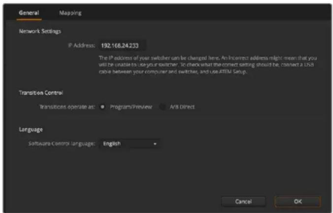
You can change the language for ATEM Software Control in the ATEM Software Control preferences.
Button Mapping
In the mapping preferences, you can assign inputs to specific buttons on the preview and program rows. The camera drop down menu lets you select a 'Blackmagic SDI' camera for each input, or you can select 'none' if you don't have a camera connected to the input.
ATEM software and hardware control panels support button mapping so you can assign your most important sources, especially cameras, to the most accessible buttons in the program and preview rows. Occasional sources can be assigned to less prominent buttons. Button mapping is set independently for each control panel so button mapping set on a software control panel will not affect the button mapping set on a hardware control panel.
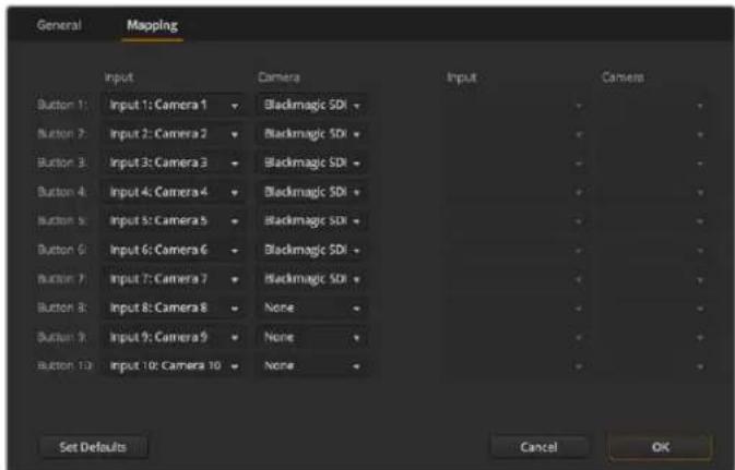
You can assign a camera from the drop down menu
Switcher Control Panel
The software control panel has four main control windows: Switcher, Audio, Media and Camera. You can open these windows by selecting the buttons at the bottom of the interface or by pressing the Shift and left/right arrow hot keys. A general settings window can be opened by selecting the gear icon at the lower left of the interface. The switcher, media, audio and camera windows all contain unique settings for the switcher, which can only be made from the software control panel.
Switcher Panel
When first launched, the switcher screen is selected, which is the main control interface for the switcher. The software control panel must be connected to a switcher to run.
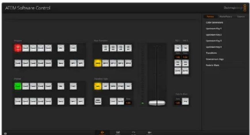
Mouse or Trackpad Operation
The virtual buttons, sliders and fader bar on the Software Control Panel are operated using your computer mouse or a trackpad if you're using a laptop.
To activate a button, click once with the left mouse button. To activate a slider, click and hold down the left mouse button while dragging. Similarly, to control the fader bar, click and hold down the left mouse button on the fader bar handle and drag up or down.
Using Keyboard Hot Keys
Hot keys can be used allowing convenient control of some switcher functions using a standard QWERTY keyboard as shown in the following table:
| Hot Keys Function | |
| <1> - <0> Previews source on switcher Inputs 1 - 10. 0 = input 10. | |
| Previews source on switcher Inputs 11 - 20. Shift 0 = input 20. | |
| Hot switches source on switcher Inputs 1 - 10 to Program output | |
| Press and release, then <1> - <0> | Hot switches source on switcher Inputs 1 - 10 to Program output. Hot switching remains on and the CUT button is lit red. |
| Hot switches source on switcher Inputs 11 - 20 to Program output | |
| Press and release, then <1> - <0> | Hot switches source on switcher Inputs 11 - 20 to Program output. Hot switching remains on and the CUT button is lit red. |
| Turns off hot switching if currently on. The CUT button is lit white. | |
| CUT | |
| or AUTO | |
More information on how to use the switcher control panel is included in the next sections.
Media Manager
The media manager allows you to upload graphics and image sequences to the media pool in the ATEM switcher. Each ATEM switcher model has memory for graphics that's called the media pool. This memory varies in size between different ATEM models and holds images with an alpha channel that can be assigned to a media player for use in the production.
| ATEM Switcher Model Still Graphics Video Clips | |||
| ATEM Constellation 8K | HD 64 4 | ||
| Ultra HD 64 4 | |||
| 8K | 24 | 2 | |
| ATEM 4 M/E Broadcast Studio 4K | 64 2 | ||
| ATEM Production Studio 4K | 20 2 | ||
| ATEM 2 M/E Production Studio | 32 2 | ||
| ATEM 1 M/E Production Studio | 32 2 | ||
For example, your ATEM 4 M/E Broadcast Studio 4K could have the maximum 64 still graphics and 2 clips loaded that will be used on your live production and then you can assign each of the media players to various stills as you work. As you take a graphic off air, you can change the media player graphic to the next graphic you want, and then you can put that media player back on air with the new graphic. ATEM Constellation 8K holds clips up to 100 frames long and has one media player in 8K mode. In HD and 4K Ultra HD mode it has 4 media players and the media pool is shared between media players. For more information about clip lengths for different models and video formats, see 'Clip Length Table'.
When a still or clip is loaded into the media pool, the alpha channel is loaded automatically if one is included in the image. When a still or clip is loaded into a media player, the output of the media player will include both key and fill outputs. If you select a media player as a key source, for example Media Player 1, both the fill and the key are automatically selected so you don't have to select them separately. However the key can still be routed separately so you can use a different key source if you wish.
Audio Mixer
The Audio tab in ATEM Software Control contains an audio mixer interface which becomes active when controlling any ATEM switcher.
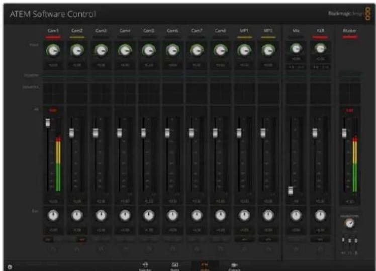
ATEM switchers include a built-in audio mixer that lets you use the embedded HDMI and SDI audio from your cameras, media servers and other inputs without the need for an external audio mixer. This is perfect when using an ATEM switcher on location or in small spaces within modern OB vehicles as you don't have to find room for an external audio mixer. The audio is mixed in the Audio tab of ATEM Software Control and output via the SDI and HDMI program outputs.
Your ATEM switcher features built in XLR and RCA inputs for mixing external audio. Mixed audio can also be output via the XLR outputs and the audio mixer contains independent controls for setting the audio level and also for selecting solo audio monitoring.
All ATEM production and broadcast studio switchers, except for ATEM Production Studio 4K, mix audio from the switcher's built in media players. ATEM Production Studio 4K does not mix audio from the media players because this model supports still frames only in the media pool and does not support motion clips.
If you prefer to use an external audio mixer, it's easy to disable the audio for all inputs and you only need to leave the external audio active in the audio mixer interface. More information on how to use the audio mixer is included in the next sections.
Camera Control
The Camera tab in the software is where you can control cameras remotely, in a similar way to how traditional external camera control units can control cameras, however with
ATEM switchers, this functionality is built into the software so it's always available. Settings such as iris, gain, focus, detail and zoom control are easily adjusted using compatible lenses, plus you can color balance cameras and create unique looks using the DaVinci Resolve primary color corrector that's built into the Blackmagic cameras running software v1.8.1 or later.
For detailed information on how to use the powerful camera control features, refer to 'Using Camera Control' in the 'Using ATEM Software Control' section of this manual.
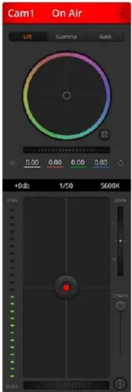
The ATEM Camera Control lets you control Blackmagic Design cameras
Switcher Settings
Click on the settings cog icon to open the settings window which allows you to change the video input selections and labels. Setting labels are important, and they are visible in the multi view output as on-screen labels and on the broadcast control panel in the source names row.
In the settings window, you can also set the switcher video standard. This is the master video standard that the whole switcher operates at, and it's very important you set this to the same video standard as your video inputs. More details on setting the video standards are included later in this manual.
The switcher settings also let you customize your multi view. The arrangement of the multi view screen can be changed by clicking on the presets at the bottom right of the M/E 1 Control Panel, or the right side of the Settings window on the M/E 2 Control Panel. On all ATEM production
and broadcast studio switchers, the arrangement for the 8 smaller video views are fully routable allowing you to view any source in the switcher. ATEM Constellation 8K is even more flexible, giving you the option to customize the multi view to show any combination of 4, 7, 10, 13 or 16 sources in the switcher.
This lets you monitor cameras, internal sources, media players and even aux outputs on a single monitor. Multiview saves space when doing portable location based events because you only need a single monitor.
If you are connecting Blackmagic HyperDeck disk recorders to your switcher, you can use the switcher settings to enter their IP address, view their connection status, and change the frame offset and auto roll settings so you can switch cleanly to a HyperDeck video source. For more information about using HyperDeck disk recorders with your ATEM switcher, refer to the 'HyperDeck control' section of this manual.
You can also set your switcher's remote behaviour using the 'remote' tab. This allows you to use the RS-422 port on your switcher to control pan, tilt, zoom heads or legacy GVG100 hardware such as linear edit suites.
Switcher settings are explained in detail in 'Changing Switcher Settings' of 'Using ATEM Software Control' section of this manual.
Using the Software Control Panel
The switcher window is the main control interface for the switcher. During live production, the switcher window can be used to select sources and take them to air.
You can select the transition style, manage upstream/downstream keyers and turn on/off the fade to black. The palettes on the right hand side of the interface are where you adjust transition settings including transition rates, adjust color generators, control media players, and adjust the upstream and downstream keyers as well as control fade to black rate.
Mix Effects
The Mix Effects block of the switcher tab contains all the source select buttons for the program and preview buses, allowing external inputs or internal sources to be selected for next transition previewing or switching to air.
If your switcher has 2 Mix Effects panels, you can optimize the interface to show both, or select each panel by clicking on the Mix Effects 1 or Mix Effects 2 buttons at the top of the interface. When both panels are visible, the Mix Effects 1 or 2 buttons will move to the processing palettes.
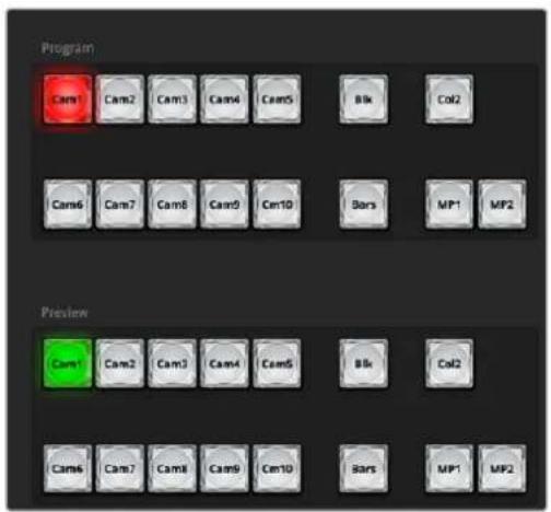
ATEM Mix Effects
Program Bus Source Select Buttons
The program bus source select buttons are used to hot switch background sources to the program output. The source currently on air is indicated by a button that is illuminated red.
Preview Bus Source Select Buttons
The preview bus source select buttons are used to select a background source on the preview output, this source is sent to the program bus when the next transition occurs. The currently selected preview source is indicated by a button that is illuminated green.
The source select buttons for the Program bus match the Preview bus.
INPUTS
Input buttons match the number of external switcher inputs.
BLACK
Color black source internally generated by the switcher.
SUPERSOURCE
This feature is active on all ATEM switchers with more than 1 M/E. Shift select for Bars.
BARS
Color bars source internally generated by the switcher. This is a dedicated button when using single Mix Effects switchers.
COLOR 1
Color sources internally generated by the switcher. Shift select for Color 2.
MEDIA 1 and 2
Internal media players that display stills or clips stored in the switcher. When using an ATEM switcher with more than 2 media players, hold the shift button down on your keyboard to reveal the additional media player buttons on the preview and program rows.
PGM 2
This button is only present on 2 M/E switchers and allows a Mix Effects 2 setup to be instantly brought to air or previewed. On ATEM 4 M/E Broadcast Studio 4K you can also select M/E 3 and 4.
Transition Control and Upstream Keyers
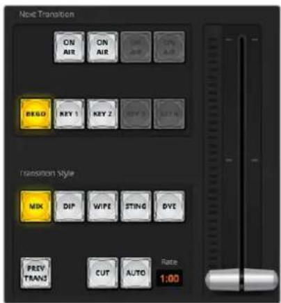
Transition Control
CUT
The CUT button performs an immediate transition of the program and preview outputs, overriding the selected transition style.
AUTO/RATE
The AUTO button will perform the selected transition at the rate specified in the 'rate' display. The transition rate for each transition style is set in the transition palette for that style and is displayed in the 'rate' window of the transition control block when the corresponding transition style button is selected.
The AUTO button illuminates red for the duration of the transition and the 'rate' display updates to indicate the number of frames remaining as the transition progresses. If an ATEM broadcast panel is connected, the fader bar indicator on the panel updates to provide visual feedback on the progress of the transition.
Fader Bar
The fader bar is used as an alternative to the AUTO button and allows the operator to manually control the transition with a mouse. The AUTO button illuminates red for the duration of the transition and the 'rate' display updates to indicate the number of frames remaining as the transition progresses. If an ATEM broadcast panel is connected, the fader bar Indicator on the panel updates to provide visual feedback on the progress of the transition.
Transition Style
The transition style buttons allow the operator to select one of five types of transitions; mix, dip, wipe, DVE, and stinger. The available transitions depend on your switcher model. For example, ATEM Production Studio 4K does not have DVE and stinger transitions. The selected transition style is indicated by a yellow illuminated button. Selection of these buttons will be reflected by the corresponding tab in the Transitions processing palette. For example, when you have the transitions processing palette open and click on a transition style button, the Transitions palette will match your selection so you can quickly adjust the settings.
PREV TRANS
The PREV TRANS button enables the preview transition mode, allowing the operator to verify a mix, dip, wipe or DVE transition by performing it on the preview output using the fader bar. When the PREV TRANS is selected you will see the preview output match the program output, and then it's simple to practice your selected transition with the fader bar to confirm you are going to get what you want. This is a very helpful feature to avoid mistakes on air!
Next Transition
The BKGD, KEY 1, KEY 2, KEY 3, KEY 4 buttons are used to select the elements which will transition on air or off air with the next transition. The number of available keyers depends on your switcher model. All keys can be faded on and off when the main transition occurs, or you can select just keys to transition individually, so the main transition control can be used to fade keys on and off.
When selecting the elements of the next transition, the switcher operator should look at the preview video output because it provides an accurate representation of what the program output will look like after the transition is completed. When only the BKGD button is selected, a transition from the current source on the program bus to the source selected on the preview bus will occur without any keyers. You can also select only keyers to transition, leaving the current background live throughout the transition.
ON AIR
The ON AIR indicator buttons indicate which of the keys are currently on air and can also be used to immediately cut a key on or off air.
Downstream Keyers
TIE
The TIE button will enable the DSK on the preview output, along with the next transition effects, and tie it to the main transition control so that the DSK can be taken to air with the next transition.
The DSK will transition at the rate specified in the RATE display of the transition control block. If the DSK is tied, the signal routing to the clean feed 1 is unaffected.
ON AIR
The ON AIR button is used to cut the DSK on or off air and indicates whether the DSK is currently on or off air. The button is illuminated if the DSK is currently on air.
AUTO
The AUTO button will mix the DSK on or off air at the rate specified in the DSK RATE window. This is similar to the main AUTO rate on the transition control block, however it's limited only to the specific downstream keyer. This can be used to fade up and down bugs and logos, such as live or replay bugs during production, without interfering with the main program production transitions.
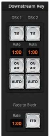
Downstream Key and Fade to Black
Fade to Black (FTB)
The FTB button will fade the whole program video output to black at the rate specified in the fade to black RATE window. Once the program output has been faded to black, the FTB button will flash red until it is pressed again. Doing so will fade up from black at the same rate, or you can enter a new rate in the Fade to Black palette in the Switcher window. Fade to black is mostly used at the start of your production, and at the end of your production, or when cutting to commercial breaks. It ensures all layers in the switcher are faded down together. A fade to black cannot be previewed. You can also set the audio mixer to fade the audio with your fade to black by selecting the AFV button on the master audio output fader.
Processing Palettes
The software control panel features tabs for the processing palette, media player, and capture options. The following processing palettes are available. These change based on the model you're connected to, and are an easy way to see what processing is available in the switcher.
Different ATEM models will have different features, so the palettes can change. The palettes also show the order of the processing in the switcher. You can expand and minimize palettes to save space and scroll them up and down to get the adjustments you need to set.
Palettes Tab
The Palettes tab contains the following processing controls.
Color Generator 1 and 2
The ATEM switcher has two color matte generators which can be configured from the color generator palette using a color picker or by setting hue, saturation, and luminance levels.
SuperSource
ATEM switchers with more than 1 M/E include a feature referred to as SuperSource (Picture in Picture or PIP) that will allow you to arrange multiple sources on the monitor at one time. For more information refer to the section 'Using SuperSource (Picture in Picture)' later in this manual.
Upstream Keys
Depending on the switcher model, ATEM has up to four upstream keyers per M/E which can be configured from the upstream key palettes. Each keyer has its own palette. Within each palette the keyer can be configured as a luma key, chroma key, pattern key or DVE. The type of key available will also depend on the switcher model and if the DVE is available. The selected palette will display all the parameters that are available to configure the keyer. More information on how to use upstream keyers is included later in this manual.
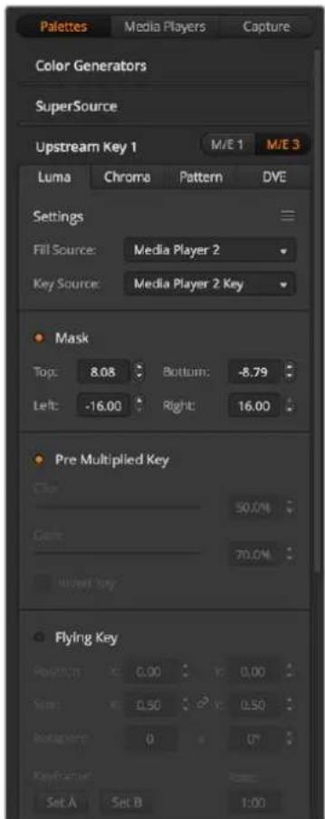
Processing Palettes
With ATEM switchers that have 1 M/E, these keyers are all labeled as being for M/E 1. On ATEM 2 M/E and 4 M/E model switchers, the labels will show which M/E these keys are connected to.
Transitions
The transitions palette is where you can configure the parameters of each transition style. For example, for the dip transition the palette has a drop down menu where you can select the dip source and for the wipe transition the palette displays all the available wipe patterns. There are lots of variations of transitions, and a large number of transitions can be created by combining settings and features in the transitions palette.
NOTE It's worth noting that simply selecting a specific style of transition in this palette will only adjust the settings for these transitions, and you still need to select the style of transition you want to perform in the transition control section on the software or hardware control panel. For ease of use, some people like to use the hardware based broadcast panel for switching, while using the software panel palettes for setting up the transition. The software and hardware panels work together and mirror all settings, so you can use any combination you like!
Downstream Key 1 and 2
The ATEM has two downstream keyers which can be configured from the downstream keys palette. The palette has drop down boxes for selecting the fill and key signals to the keyer, sliders to set the clip and gain values, pre-multiplied, and mask settings.
Fade to Black
The Fade to Black palette is where you can set the fade to black transition rate. An Audio Follow Video checkbox is also provided as a shortcut for the audio mixer's master fader AFV button. Selecting this feature lets you fade your audio with your fade to black.
Media Players Tab
The Media Players tab contains controls for your ATEM Switcher's media players and connected HyperDecks.
Media Players
Your ATEM switcher has media players which play back the clips and stills that are stored in the media pool memory built into the switcher. The drop down list is used to select the still or clip that will be played or made available on the media player input to the switcher. When a clip is selected, the transport controls in the media player can be used to play, pause and loop the clip. Controls are also provided to step forward and backward through frames of the clip. Most ATEM switchers have 2 media players. ATEM 2 M/E Broadcast Studio 4K has 4 media players.
Hyperdecks
If you are running ATEM switchers 6.8 or newer, you can connect up to 4 Blackmagic HyperDeck Studio model disk recorders and control them using ATEM Software Control's HyperDecks palette. For more information refer to the 'HyperDeck Control' section of this manual.
TIP The 'capture' tab supports legacy ATEM Production Switcher models with USB capture features.
Using the Audio Mixer
The audio tab is used to mix audio sources connected to any ATEM switcher via HDMI, SDI, external audio and also from the built-in media players in ATEM 1 M/E, 2 M/E, and 4 M/E switcher models.
Cameras, media players and external audio sources are listed along the top of the audio mixer along with the master audio output for the program outputs of the switcher.
Below each audio source is an audio level meter, a fader for setting the maximum audio level, and a knob for setting the left/right audio channel balance. The master fader on the right side of the audio mixer is used to set the gain on the audio level on the SDI and HDMI program outputs and has its own audio level meter. The monitor fader and buttons appear below the master fader and set independent audio levels and also allow solo monitoring on the audio outputs.
The buttons below each audio level meter determine whether audio is always available for mixing or only when the source is on air. The solo, or headphones, button determines whether the audio source should be used for solo audio monitoring. You can monitor through the switcher's XLR monitor output on the rear panel of ATEM Production Studio switchers or ATEM Broadcast Studio switchers.
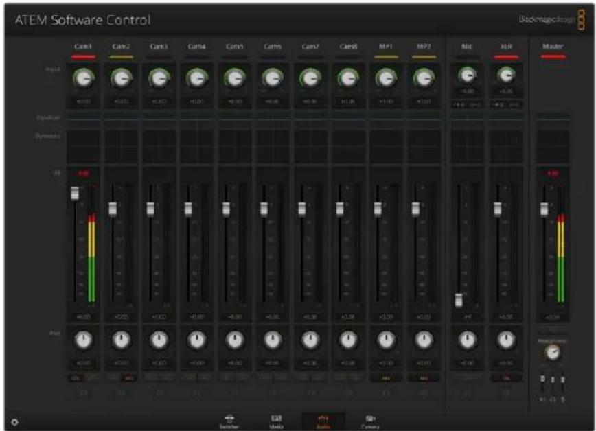
The audio mixer displays tally lights for any audio sources that are currently on air or when AFV is selected, as well as audio level, audio balance and buttons for selecting which audio should be used.
Tally
Any source whose audio is on air is lit with a red tally light in the software. External audio is on air by default so the EXT tally light is usually lit red. In the example on this page, Cam4 and Cam7 are lit because their audio is set to be always on. The tally light will be illuminated dull yellow when AFV is selected and the channel's associated camera is off air. This also applies to the master fader tally light when the master fader AFV button is selected. When FTB is activated, the master fader tally light will blink red.
Audio Level
Drag the audio level fader to set the gain on the audio level for each camera and audio source. The green number under each audio level meter shows the maximum audio level set by the fader.
The number above the audio meter shows the peak audio level reached by the audio source. A green number represents low to medium audio levels. If the audio meter is regularly showing red, and the red number above it is not changing, then you should reduce the audio level to avoid audio distortion. After adjusting the audio level, you may wish to reset the red number by clicking on it once. Observe the new number to make sure it changes for a while and does not immediately shoot up and become stuck on a red number. If it does, you may need to reduce the audio level even further.
Audio Balance
The audio mixer supports stereo audio from each audio source. If you wish to change the left/right audio channel balance for a camera or other audio source, adjust the knob to the desired balance point.
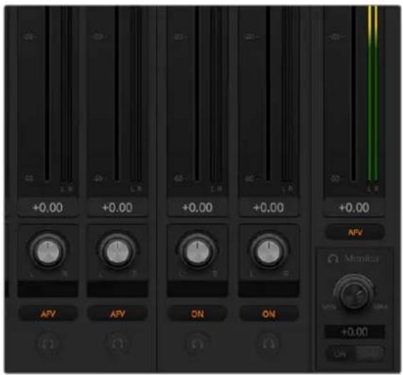
If you are operating a 2 M/E or 4 M/E ATEM switcher, and notice the solo and monitor settings are grayed out, you have program audio selected for the audio out setting in the settings window.
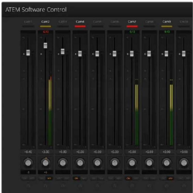
The audio meter for Cam1 is shown in gray to indicate that its audio will not be used as neither of its ON or AFV buttons are enabled. Cam2 has AFV selected but its audio is not currently being used as the camera is not on air as is indicated by its dull yellow tally light. Cam4 and Cam7 have their direct mix set to ON so their mixed audio is always used, and their tally lights remain lit, even if another camera is currently on air. The audio level meters for Cam3, Cam5, Cam6 and Cam8 show that no audio is present on these cameras.
Audio Source Selection
Below each audio level meter, you will find the ON and AFV buttons that select which audio sources are sent to the program output of the switcher.
| ON | Selecting the direct mix to ON allows an audio input to be permanently mixed into the program output, even when the associated video source is not on air. The red tally light will always be lit because the audio is always on air. Selecting this option automatically disables AFV. |
| AFV | Audio-follow-video (AFV) allows audio to crossfade when inputs change.The audio will only be sent to the program output when the input is on air, lighting the red tally light above. When off air, the tally light is lit dull yellow. Selecting this option automatically disables the direct mix ON setting. |
SOLO | ATEM Production Studio switchers and ATEM Broadcast Studio switchers can use the XLR audio output via the switcher's rear panel.Selecting solo exclusively outputs that single audio source to the monitor output so you can listen clearly to any single input when required. This is an important feature which lets you confirm audio content before putting it to air and without affecting the program output audio. When solo is deselected the audio output will return to its original state. |
Master Audio Level Output
The master fader on the right side of the audio mixer is used to set the gain on the audio level on the SDI and HDMI program outputs and has its own audio level meter. Select the AFV button on the master audio output fader to enable the AFV fade to black feature. This lets you fade your master audio when you click on the Fade to Black button.
Audio Mixer Monitor
The monitor volume knob and buttons appear below the master fader and control the monitoring audio output behavior. You can use these settings to set independent audio levels for monitoring the audio mix without affecting the program output audio. If you've selected a solo input that you want to monitor, these settings let you control the audio monitor levels for the single input without affecting the program output audio. You can enable these settings by going to the settings window and selecting the audio out setting to "monitor audio".
| AFV | Select ON to enable audio monitoring via the monitor XLR output. Deselect ON to disable all audio via the monitor XLR output. |
| DIM | Select DIM to temporarily reduce the monitor audio level without having to adjust the fader. Select DIM again to return to your preferred listening level. |
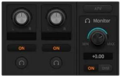
The monitor volume knob and buttons set independent audio levels and allow solo monitoring on the monitor XLR output
Headphones Settings on ATEM Constellation 8K
On ATEM Constellation 8K, the headphones settings are used to adjust the audio mix for the headphones output. ATEM Constellation 8K features a control panel with talkback controls. A headset can be connected via the 5 pin XLR connector on the front panel for communicating with camera operators. However, the headset is not just limited to talkback use as you can also use the headset microphone for doing voice overs and you can use the headset headphones for program audio monitoring.
These controls for ATEM Constellation 8K are different to ATEM Production Studio switchers and ATEM Broadcast Studio switchers that have 'monitor' XLR outputs. Instead, your headphones monitor master, talkback and sidetone audio.
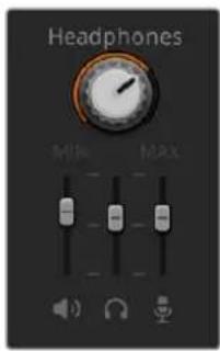
Headphones settings on ATEM Constellation 8K let you mix the levels of each monitoring output. For example, you may want to increase or decrease the level of the talkback audio against the program audio.
Master
Adjust the master level slider to set the program audio level in the headset and if you don't want to listen to program audio, then slide this control fully to the left.
Talkback
The talkback level slider sets the audio level of camera operators who are talking to you and by setting the master and talkback sliders you can get your preferred balance of talkback and program audio into your headset.
Sidetone
The sidetone level slider lets you mix your voice from your headset mic into the monitor output. This is helpful when wearing a headset that supports noise canceling.
Shaping your Audio Mix using Advanced Fairlight Controls
ATEM Constellation 8K has advanced Fairlight audio controls that let you enhance and refine the quality of sound on each input and master output, including input level controls, a 6 band parametric equalizer and powerful dynamics settings. This section of the manual shows the different Fairlight audio controls you can use to shape and optimize the audio mix in your live production.
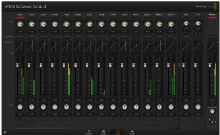
Input Level
Generally, when setting up your audio mix, the first step is to normalize all your inputs. This means adjusting the input level knob on each input so you can optimize all the levels to their highest strength without clipping.
This control is at the top of each track under the tally light. Change the level by clicking on the knob and dragging left to decrease the level, or right to increase. By setting the input control, it brings all the inputs up to a common signal strength so they are all at their strongest without clipping. Then you can start making advanced changes and refinements.
After you have normalized all your input levels, you can now begin optimizing and shaping the qualities in each audio input using the 6 band parametric equalizer and dynamics controls.'
Using the 6 Band Parametric Equalizer
Each input and the master output, has a 6 band parametric equalizer which can be used to control specific frequencies. This could include reducing low frequency hum or noise on a microphone input, or boosting the low frequencies on a thin sounding track, or even to add uniqueness to each input so they are more distinct in the final mix. You have many creative options.
Parametric Equalizer
To open the parametric equalizer for an input or the master output, click on the corresponding equalizer indicator.
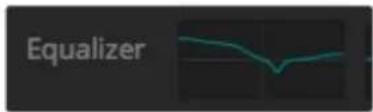
Click on an input's equalizer indicator to open a 6 band parametric equalizer
The first item you will notice is the graph along the top of the window with numbered indicators from 1 to 6. These numbered indicators are adjustable handles that correspond to bands 1 to 6.
Each band of the 6 band parametric equalizer has a column of settings. These settings will differ based on which band you are controlling and what filter type you are using.
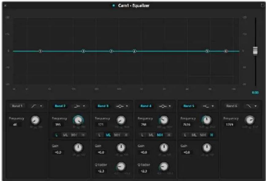
Each audio input has its own 6 band parametric equalizer
If you want to make changes to a setting, you will first need to make sure the band is enabled. Click on a band label to enable it. When enabled, the button label is illuminated blue. Now you can change the settings for that band, or click and drag the handles to make fast adjustments.
TIP You can learn more about band filters later in this section.
Handles
Each band handle is positioned along the line curve displayed in the graph. You can click and drag each handle to choose the frequency you wish to adjust for that band and the gain you want to set. When moving a handle with your mouse, both the frequency and gain settings are affected simultaneously, which gives you a fast way to make quick adjustments to each band across the entire range of frequencies.
NOTE To make changes using a handle, ensure the band is enabled. Simply click on the band you want to adjust. The band label will illuminate blue when enabled.
As you drag a handle left or right, you will notice the frequency and decibels update in the band settings. This will also be reflected by the frequency range preset buttons for low, medium low, medium high and high.
Frequency Knobs
Alternatively, you can use the frequency knobs for each band to select a specific frequency to adjust.
Range Presets
The frequency range for each band is defined by the range preset buttons. For example, low is labeled 'L' and covers the frequency range from 30 to 395 Hz.
As a quick example of how the range presets define the frequency range, select a notch filter from the band filter dropdown list and then click on each range preset. You will see the filter effect move to a position along the graph curve that corresponds to the range preset you choose. This lets you quickly define a specific range of frequencies you want the filter to affect.
Below is a table showing the range of frequencies for each range preset setting.
| Range Preset Frequency Range | |
| Low 30 Hz to 395 Hz | |
| Mid Low 100 Hz to 1.48 kHz | |
| Mid High 450 Hz to 7.91 kHz | |
| High 1.4 kHz to 21.7 kHz |
Gain Knobs
Click and drag the gain knob left or right to decrease or increase the volume level for the selected frequency.
Q Factor
The Q factor control is available when the bell filter is applied to bands 2, 3, 4 and 5. This sets the range of frequencies the filter will affect. For example, setting the minimum will allow the filter to affect a wide range of surrounding frequencies and the maximum setting will narrow the effect down to a tiny point. This is important if you have sound qualities in surrounding frequencies that you want to either include or exclude from the change you are making.
As you adjust the Q factor, watch the shape of the effect on the line curve change from a broad, rounded edge to a sharp point. This is a visual representation showing how the regions of frequencies surrounding the target frequency are affected.
TIP Compare the audio with changes against the original unaltered audio by clicking on the bypass button at the very top of the equalizer window. This lets you turn the equalizer on or off.
Band Filters
There are six different types of band filters you can choose from. These filters include bell, high shelf, low shelf, notch, high pass and low pass. These filters let you control specific zones within the frequency range. For example, a low shelf filter lets you increase or decrease the level of volume for lower frequencies on the graph, and a high shelf filter controls the higher frequencies.
Try setting a low shelf filter to band 3 and make changes to the gain setting. You will see the changes are weighted towards the low end frequencies on the graph.
A description for each filter type is provided below.
Bell High Shelf Low Shelf
This filter is used to increase or decrease a range of frequencies surrounding a defined frequency.
Lets you increase or decrease the level of volume for higher frequencies along the graph.
Lets you increase or decrease the level of volume for lower frequencies along the graph.
Notch High Pass Low Pass
This filter lets you remove, or cut, a defined frequency.
Smoothly removes extreme low end frequencies, allowing the high end frequencies to pass unaffected.
Smoothly removes extreme high end frequencies, allowing the low end frequencies to pass unaffected.
TIP It's not uncommon to have filters on each band overlapping on the graph curve with adjustments working together. For example, you may have a low shelf filter applied to band 4 and a notch filter on band 5 reducing a frequency within the same range.
Dynamics Controls
In addition to the 6 band parametric equalizer, you can also enhance and finesse the input and master output audio using dynamics controls. Where the equalizer lets you control the frequencies within a signal, dynamics controls let you set how various levels behave. Levels within the signal can be adjusted including expanding the dynamic range between low levels and high levels, gating an input so you can choose what is stronger or softer within a signal, or you can even use the compressor and limiter so that audio can be generally lifted and made stronger without clipping.
Combined with equalizer controls, these features are extremely powerful, giving you the ability to precisely shape and define the audio to generally optimize the sound of the master output.
This section describes the expander, gate, compressor and limiter controls.
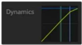
The dynamics controls can be opened for each input and the master output by clicking on its corresponding dynamics indicator
Common Dynamics Settings
The expander/gate, compressor and limiter share common settings that let you shape how each function affects the audio. For example the level at which the function initiates, how long the function is applied, the strength of the function, etc. The settings available differ depending on the dynamics control you are using.
Threshold – Sets the sound level at which the function activates. For example, setting the threshold for the compressor to -20dB tells your switcher to activate compression when the signal rises above -20dB. Alternatively, setting the expander to -40dB means the switcher will only initiate the expander once the signal level drops below -40dB.
Range - This setting defines the range of decibels affected by the function.
Ratio - Defines the maximum strength of the function once initiated.
Attack – Sets the smoothness of the function when it initiates. For example, a long attack will allow the function to fade into the signal, blending in better without drawing too much attention, whereas a short attack may be better for complex sound activity with many quick variations where a longer attack may cause artifacts.
Hold - Sustains the dynamics function over an adjustable period of time.
Release - Similar to attack but occurs at the end of the function activity. For example, lets the dynamics function ease out gradually, or fall away rapidly, once the level moves out of the threshold.
Expander/Gate
The first set of dynamics parameters can be switched between expansion and gating.
Expansion emphasizes differences in volume by lowering the level of soft parts of the signal relative to the level of louder parts. You can use an expander to emphasize the differences between quiet and loud parts of a track, or to increase the dynamic range of a signal and minimize unwanted noise.
Gating is like an exaggerated expander, reducing the level or even silencing parts of a signal that fall below a certain level in order to reduce or eliminate noise in quiet parts of a recording. For example, a range of 15 to 20 dB can reduce breathing in a vocal track but leaves just enough to sound natural.
Gating is extremely effective, but it's also very powerful so requires careful attention. If the gate threshold is set too high it can cause artifacts, such as cutting off the start of a syllable or the quiet end of a word. You can compensate by reducing the threshold slightly, or by increasing the attack or release time.
Compressor
Compression lets you reduce peaks in an audio signal, reducing the dynamic range of a signal, so you can boost the overall level without clipping. This is helpful when you want to make sure the loud elements in a signal don't diminish the strength of quieter sounds, or to smoothen changes in audio levels within the signal.
TIP It's a good idea to apply the compressor after you have set the EQ controls.
Make Up
The make up setting lets you increase the overall signal in combination with compression settings. With loud parts of the audio reduced using compression, you can now use the make up control to boost the overall sound without clipping.
Limiter
The limiter prevents peaks of the signal from exceeding a set maximum level. A limiter is helpful to prevent hard clipping. For example, if you set the limiter to -8 dB, the input signal will never exceed that level. Adjusting the attack, hold and release settings will set how gentle the limiter affects the signal.
Dynamics Controls Characteristics
| Control Minimum Default Maximum | |||
| Expander/GateExpander Controls* | |||
| Threshold -50dB -45dB** 0dB | |||
| Range 0dB 18dB 60dB | |||
| Ratio 1.0:1 1.1:1 10:1 | |||
| Attack 0.5ms 1.4ms 30ms | |||
| Hold | 0.0ms | 0.0ms | 4s |
| Release | 50ms 93ms 4s | ||
| Gate Controls* | |||
| Threshold | -50dB | -45dB** | 0dB |
| Range 0dB 18dB 60dB | |||
| Attack 0.5ms 1.4ms | 30ms | ||
| Hold | 0.0ms | 0.0ms | 4s |
| Release | 50ms 93ms 4s | ||
| CompressorCompressor Controls | |||
| Threshold -50dB -35dB 0dB | |||
| Ratio 1.0:1 2.0:1 10:1 | |||
| Attack 0.7ms 1.4ms 30ms | |||
| Hold 0.0ms 0.0ms 4s | |||
| Release 50ms 93ms 4s | |||
| LimiterLimiter Controls | |||
| Threshold | -50dB | -12dB | 0dB |
| Attack 0.7ms | 0.7ms 30ms | ||
| Hold 0.0ms 0.0ms | 4s | ||
| Release 50ms 93ms | 4s | ||
* Master Dynamics expander/gate controls are unused in Master Dynamics.
** Master Dynamics expander/gate threshold default is -35dB. Mic Dynamics and XLR Dynamics expander/gate threshold default is -45dB.
Fairlight Controls Workflow Guide
This section describes a basic workflow to help you get started using the Fairlight controls to refine and enhance your audio mix.
Generally, the first step to optimizing your mix is to normalize all the inputs so they are all at their maximum strength without clipping. This is normally done by increasing or decreasing the input gain level for each input so their signal peaks just below 0dB on the channel strip's level indicator.
2 If you want to split any mono inputs into two separate channels for stereo output, go to the general switcher settings and navigate to the audio tab. Enable the checkboxes for the mono inputs you want to change to stereo. Click 'done'.
TIP If you want to split mono inputs into two separate channels, it's best to do this before normalizing the input as described in step 1, so that you can normalize both channels after they have been split.
3 Now, click on the EQ indicators below input level controls and make equalization changes to each input. You can move the windows into a better position, or close them if needed.
4 After setting EQ, open the dynamics controls for each input by clicking on their respective dynamics indicator. Make the required dynamics changes to generally improve and refine the input audio.
5 With EQ and dynamics set for each input, you can now open the EQ controls for the master output and sweeten the final audio mix.
6 Now open the master output's dynamics controls and make any required changes to improve the final output.
Once all the Fairlight controls are set, you can then increase or decrease the faders on the audio mixer to set them at their best levels for the live mix and make adjustments where necessary during the production. You can also go back to any of the settings and make further adjustments if needed, but it's best to follow the same order as described above to get the best results from each function. For example, it's important to set EQ controls before making dynamics changes as the processing chain in your switcher applies dynamics to the audio after equalization.
Most important of all is to apply the effects carefully so your audio still sounds natural but exciting too!
Navigating the Browse Window on the Media Page
The browse window is a simplified file browser that lets you navigate your computer to look for graphics files. All attached drives on your computer are displayed and you can select folders from them. View sub folders by clicking on the arrows next to each folder.
The Preview window will show any selected graphics files.
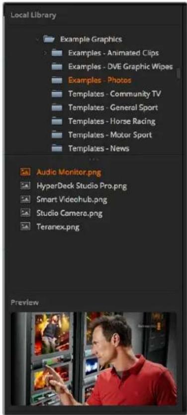
Browse window
Browsing and loading files
Loading a still is as easy as dragging it from the browse window and dropping it into an empty slot in the Media Pool. To load a motion clip, you'll need to load a sequence of still images. To select a sequence, click on the first file in the sequence, scroll down and shift click on the last file in the sequence. Now the highlighted file sequence can be dragged into any of the two clip slots in the media pool. You can load audio files to accompany your clip, for example when playing a stinger transition, by dragging the audio file from the browser and dropping it into the audio slot next to the clip slot. You can identify the audio slot by its audio icon.
When dropping a still, clip or audio file into a slot, a progress indicator will show the loading status. You can drop multiple files into the media pool, even if the first images have not yet completed loading, as they will continue to load one after the other. If a clip or still is dropped into a window which already has content loaded, the existing content will be replaced.
The ATEM media pool supports PNG, TGA, BMP, GIF, JPEG and TIFF still image formats. Audio files must be WAV, MP3 or AIFF.
ATEM Media Pool
When files have been loaded into the media pool, the still and clip slots will show a thumbnail image. Clip slots will display the image from the middle of its loaded sequence. Above the clip slots you'll see information showing the number of frames in a loaded clip, plus the maximum number of frames that can be loaded for your selected video format. Stills are marked with a slot number so you can identify them when assigning a still image to the media player using a broadcast panel.
The file name for each loaded still or clip is displayed underneath the slot so you can keep track of stills and clips you have loaded. This is very useful, as in the media player palette in the switcher tab, as well as the Photoshop plug-in, you will see a list of media pool still and clip numbers as well as the file name.
Numbers are displayed on slots in the media pool to clearly show which slots are assigned to the relevant media players. When a media player slot is switched to the program output, the media player number on the slot changes to red to indicate the slot is on air. When a slot is on the preview output, the media player number changes to green. When using an ATEM switcher with more than 2 media players, hold the shift button down on your keyboard to reveal the additional media player buttons on the preview and program rows of the software control panel.
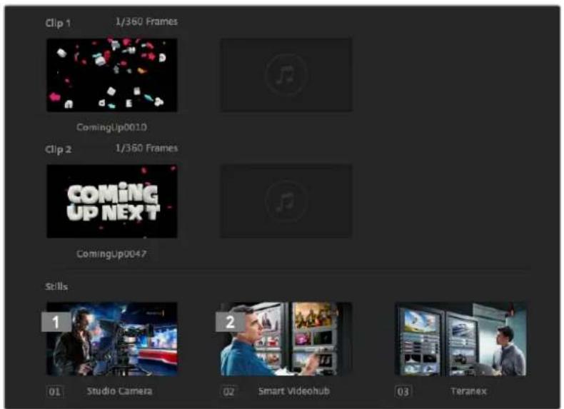
ATEM Media Pool
You can change the media player assignment from the media tab by selecting your desired clip or still from the 'media' dropdown list. Simply click on the arrow in the player 'media' list to select from a list of media pool slots.
You can also assign media players to stills or clips from the hardware based ATEM broadcast panels, or in some cases from the Photoshop plug-in when downloading stills.
Changing Switcher Settings
Clicking on the switcher settings 'gear' icon will open the settings window where you can change general switcher settings, Multi View, label, HyperDeck and remote settings. These settings are divided into tabs.
General Settings
Setting the Switcher Video Standard
The video setting is used to select the operating video standard of the ATEM switcher and this must be set to the same video standard as the video sources you are plugging into the ATEM switcher. If they don't match, the inputs won't appear correctly and will most likely remain black. A good way to work out the video standard you should use is to check cameras and and then set the switcher video standard to the same format.
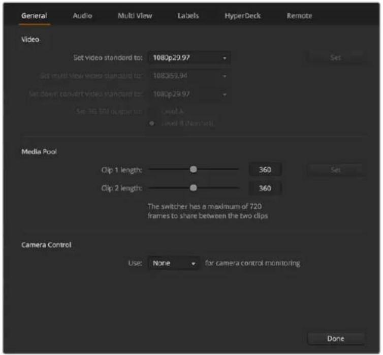
Change switcher settings
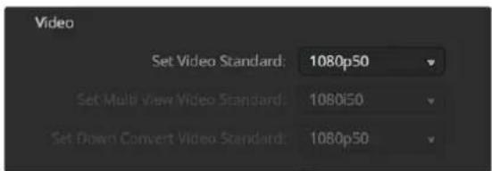
Set video standard
ATEM currently supports the following video standards:
| ATEMConstellation 8K | ATEM4 M/E Broadcast Studio 4K | ATEMProduction Studio 4K Models |
| --525i59.94 NTSC 4:3 | ||
| --625i50 PAL 4:3 | ||
| --252i59.94 NTSC 16:9 | ||
| --625i50 PAL 16:9 | ||
| 720p50 720p50 720p50 | ||
| 720p59.94 720p59.94 720p59.94 | ||
| 1080i50 1080i50 1080i50 | ||
| 1080i59.94 1080i59.94 1080i59.94 | ||
| 1080p23.98 1080p23.98 1080p23.98 | ||
| 1080p24 1080p24 1080p24 | ||
| 1080p25 1080p25 1080p25 | ||
| 1080p29.97 1080p29.97 1080p29.97 | ||
| 1080p50 1080p50 1080p50 | ||
| 1080p59.94 1080p59.94 1080p59.94 | ||
| 2160p23.98 2160p23.98 2160p23.98 | ||
| 2160p24 2160p24 2160p24 | ||
| 2160p25 2160p25 2160p25 | ||
| 2160p29.97 2160p29.97 2160p29.97 | ||
| 2160p50 | 2160p50 | - |
| 2160p59.94 2160p59.94 - | ||
| 4320p23.98 | -- | |
| 4320p24 -- | ||
| 4320p25 | -- | |
| 4320p29.97 | -- | |
| 4320p50 | -- | |
| 4320p59.94 | -- |
To set the video standard, select the video standard from the menu and then select the set button. Any time the video standard is changed, it will erase any frames you have loaded into the media pool.
Setting the Multi View Video Standard
Use this dropdown menu to select the video standard on ATEM switchers that can support Ultra HD multi view output, such as ATEM 4 M/E Broadcast Studio 4K or ATEM Constellation 8K.
The multi view output on ATEM Constellation 8K supports four 4K Ultra HD or HD outputs or one 8K output up to 4320p59.94 so you can monitor at higher quality when you connect an 8K monitor or television. ATEM 4M/E Broadcast Studio 4K supports up to 2160p59.94. If you set your ATEM to 2160p50 or 2160p59.94 video, the multi view will be automatically displayed using 2160p25 or 2160p29.97 respectively so you can use a wider range of Ultra HD televisions. However if you want to use a standard HD television, then you can also set the multi view outputs to be down converted to HD for even greater monitor compatibility.
For example if your ATEM is selected to run at 2160p59.94 then the multi view will output at 2160p29.97 when the multi view setting is selected to Ultra HD, or you can choose to output 1080i59.94, 1080p29.97 or 1080p59.94 when the multi view output is selected to regular HD.
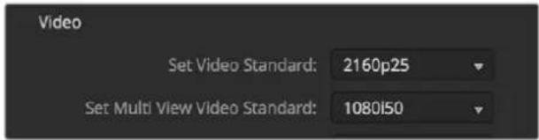
Set Multi View video standard
For all other switcher models the multi view output is always HD even when running in standard definition so you can see all your sources in higher resolution. When switching Ultra HD video at 59.94 or 50 frames per second, the multi view will display HD video at 29.97 or 25 frames per second respectively.
Setting the Down Converter Outputs
When running ATEM Production Studio 4K models in Ultra HD, the HD-SDI program output always outputs down converted high definition 1080i video for connection to HD-SDI equipment. High definition or standard definition video inputs are always output as HD or SD video respectively.
ATEM 4 M/E Broadcast Studio 4K has 1 down converted program output that will default to 1080p29.97 when switching Ultra HD video at 2160p59.94, or 1080p25 when switching 2160p50.
When running the ATEM 1 M/E and 2 M/E production switchers in high definition, the HD signal is permanently down converted to SD via SDI and composite video outputs for connection to older devices. 720p50 and 1080i50 down converts to 625i50 PAL. 720p59.94 and 1080i59.94 down converts to 525i59.94 NTSC.
Down conversion provides the following aspect ratios:
| Center Cut Crop left and right side making a 4:3 image. | |
| Letterbox Scales the video down with black bars to top and bottom. | |
| Anamorphic | Horizontal scale (squeeze) to make 16:9 image fit 4:3. Requires an anamorphic or 16:9 monitor or television to correct the aspect ratio. |
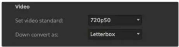
Setting the down converter standard
Set 3G SDI Output Level
If you're outputting HD video to equipment with 3G-SDI inputs, you may need to toggle between level A and B 3G-SDI output standards to maintain compatibility with equipment that can only accept level A or B 3G-SDI video. Level B is the default setting that works with most equipment, but you can switch to Level A by clicking the 'level A' radio button.

Setting 3G-SDI Output Level
Setting the Audio Output Behavior
The ‘audio’ tab lets you control the audio monitoring settings, such as selecting the program audio or monitor audio via the XLR outputs. Instead of XLR monitor outputs on ATEM Constellation 8K, you can use the MADI out BNC connectors.
Program audio is the same audio that the audio mixer sends to the SDI and HDMI program outputs. Monitor settings and solo monitoring are disabled in the audio mixer when program audio is selected.
Monitor audio allows you to listen to the program audio mix of all inputs, or just a solo input, at your preferred volume level and without affecting the audio on the program output. You can monitor the solo audio source even if it is not on air.
These monitor settings are only available to the audio mixer when monitor audio is selected for the audio out setting in the settings window.
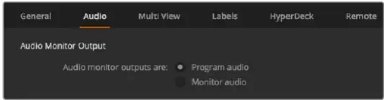
Set the audio output behavior
SDI Audio Channels 15 and 16
You may want to loop one of your ATEM's outputs to an input to achieve a desired effect. In some cases this can cause a feedback loop in SDI audio channels 15 and 16. If this occurs, you can mute SDI channels 15 and 16 by clicking the 'mute' checkbox in the audio options located in the general switcher settings.
Talkback on ATEM Constellation 8K is embedded in SDI channel 13, 14, 15 and 16.
If you're using Blackmagic Design products for talkback, such as ATEM Talkback Converter 4K and ATEM Camera Converters, muting SDI channels 15 and 16 from your switcher will not affect talkback functionality.
Mix Minus Settings
The mix minus settings on SDI outputs let you mute the audio from their return program feed. For example, when doing live crosses there can be a delay in the audio which may be distracting when the presenter can hear his or her own voice delayed on the program return feed. Enabling mix minus for an input will output all program audio in the mix, minus that particular input.
TRS Inputs
If you are plugging in an audio source via RCA using an RCA to TRS adapter, then you can change the input level on the TRS input from TRS to RCA. This boosts the signal at the input to compensate for the lower output levels from equipment using RCA connectors, for example HiFi audio equipment.
Split Audio
On ATEM Constellation 8K you can split a mono input signal into two separate mono channels. This is helpful for mixing a mono input into both channels on the stereo master output.
Click on the desired input checkbox to split the channels for that input.
Adjusting the Media Pool Clip Length
For models that support media clips, the media pool features two clips that share the same pool of memory. ATEM Constellation 8K can store two 8K clips and four HD or Ultra HD clips. By default, each clip receives equal amounts of the available memory which determines the maximum number of frames. If you need a clip to be longer, adjust the balance of frames. It's worth remembering that lengthening one clip will shorten the other.
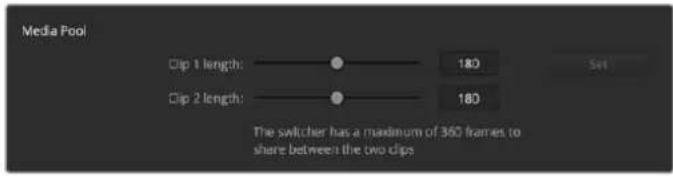
Setting the Media Pool Clip Length
Clip Length Table
| ATEM Switcher Video Format Clip Length | ||
| ATEM Constellation 8K | 720p 3200 frames | |
| 1080i, 1080p 1600 frames | ||
| 2160p 400 frames | ||
| 4320p 100 frames | ||
| ATEM 4 M/E Broadcast Studio 4K | 720p 3200 frames | |
| 1080i, 1080p 1440 frames | ||
| 2160p 360 frames | ||
| ATEM 1 M/E and 2 M/E Production Studio 4K | SD 900 frames | |
| 720p 360 frames | ||
| 1080i 180 frames |
Camera Control Auxiliary Output
If your switcher features auxiliary outputs, you can select which one will monitor the ATEM Camera Control output. Set your desired aux output by opening 'settings', then selecting from the 'auxiliary for camera control output' drop down menu. Auxiliary output buttons can also be renamed in settings by adjusting the input labels. With ATEM Constellation 8K, you can select any SDI output for camera control.

You can output the camera control via any of your switcher's auxiliary outputs.
Multi View Settings
The multi view settings allow you to set the multi view orientation. The 8 smaller windows are fully routable so you can monitor any switcher source. By default, external inputs 1 - 8 are routed to multi view source windows 1 to 8, but click the menus to select what sources are viewed on each window!
ATEM Constellation 8K has one 8K multi view, or four multi view outputs in HD or Ultra HD. The 8K multi view lets you choose configurations of 4, 7, 10, 13 or 16 views. You also have the option of replacing both of the large preview and program views with an extra 8 small and fully routable views to create a 16 view layout.
If you are using ATEM 6.9 or newer, you can swap the position of the multi view preview and program views by clicking on the toggle button located between them.
The multi view settings also include the option to turn the safe area indicators inside the views on or off. Simply click on the safe area icon in the preview window.
Audio meters can be turned on or off for all the switcher sources and program view by enabling the 'All On' button in the multi view settings, or you can turn them on or off individually by clicking the audio meter icon in each view.
The multi view also includes a tally feature, so if any of the sources in the multi view are used in a layer on the program or preview outputs, they will be highlighted red or green. A white border means your source is not currently on the preview output, or on air on the program output. A red border indicates the source is used on the program output and a green border indicates a source is selected on the preview output.
The preview window on the multi view output features safe area markers so you can make sure your program will look great on any monitor. In HD, the outer border represents the 16:9 graphics safe area and the inner border represents the 4:3 graphics safe area. In SD, the single border represents the action safe area. You can also change the orientation of the multi view windows by selecting one of four different layouts using the icons at the bottom of the multi view settings window.
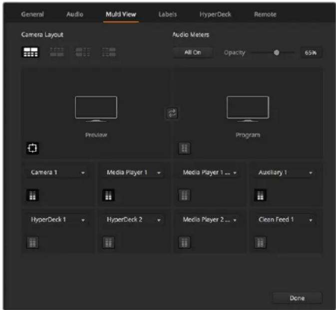
Customizing the Multi View
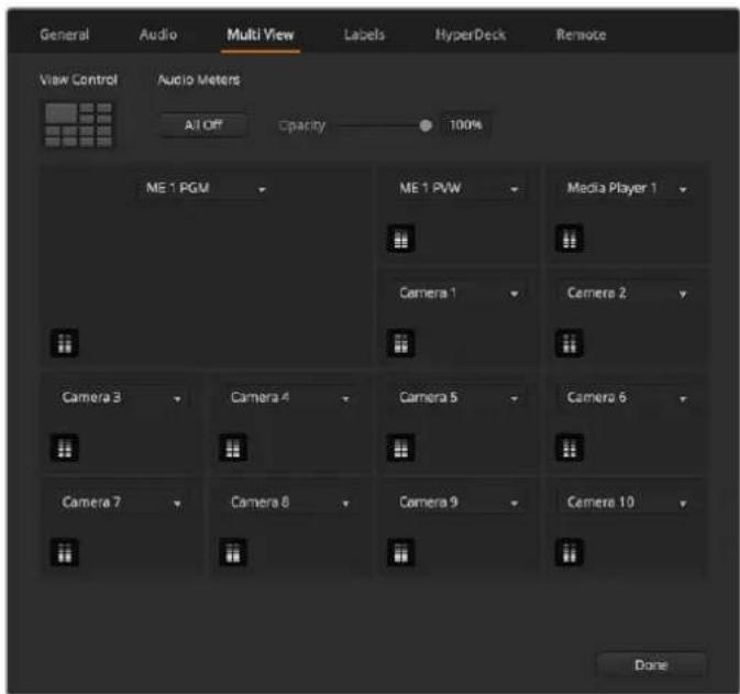
Multi View layout options for ATEM Constellation 8K.
Labels Settings
The video input settings are used to select the inputs and change labels. Depending on your ATEM switcher model, some video inputs can select between different video sources, such as HDMI or SDI. You can identify switchable connections on the rear of the switcher because all inputs are numbered and any inputs that can switch will have the same input number on their label.
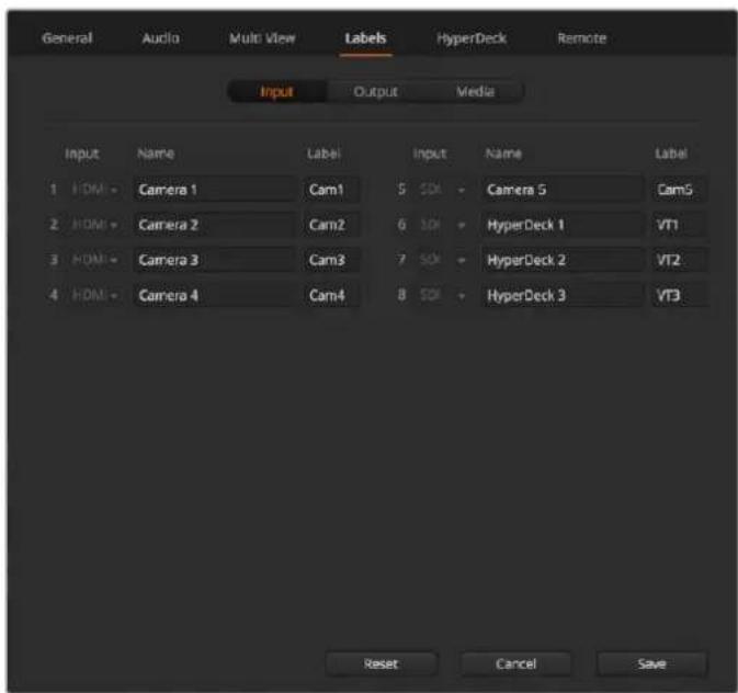
Label settings
For example, ATEM 1 M/E Production Studio 4K shares the Input 1 setting between an HDMI and SDI connector, which are both labelled Input 1 on the back panel. In the 'video inputs' window, click input 1 to select between HDMI and SDI.
Inputs can have customized labels and these labels appear on ATEM broadcast control panels and on the multi view. Long and short labels need to be entered, as long labels are often too long to be displayed on broadcast control panel's smaller displays.
A short 4 character name is used to identify the video input on the source names display of the broadcast panel. The longer input names support up to 20 characters and are displayed in various dropdown source selection boxes on the software control panel and also on the multi view windows on screen labels.
To change an input name, click in the text field, enter the text and select set. The input name will be updated on the multi view, software control panel and broadcast panel if one is connected. It's a very good idea to change both the short and long labels at the same time, so they match. For example Camera 1 would be entered in as a long label and CAM1 as the short label.
HyperDeck Settings
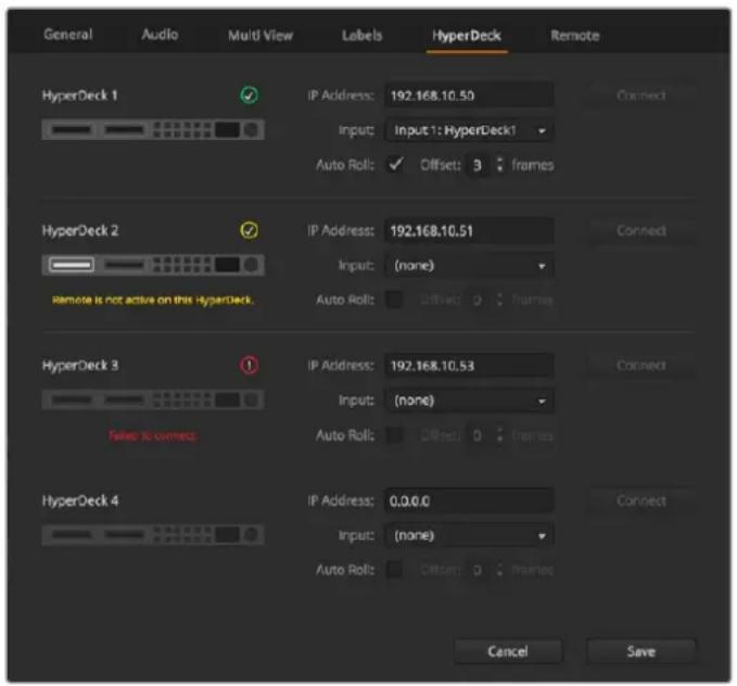
HyperDeck settings
With ATEM 6.8 or newer, you can connect up to 4 Blackmagic HyperDeck Studio disk recorders and control them using ATEM Software Control. When connecting HyperDecks, use these settings to configure the IP Address, select the inputs your HyperDecks are connected to, turn the auto roll feature for each deck on or off and set their frame offset settings so they can switch cleanly.
Status indicators appear above and below each deck so you can see if they are successfully connected and if their remote buttons are active.
For detailed information on setting up Blackmagic HyperDecks with your ATEM switcher and setting the 'HyperDeck' configuration settings, refer to the 'HyperDeck Control' section of this manual.
Remote Settings
If your switcher has an RS-422 port, you can select how it is used with the 'remote' checkbox. The options are disabled, VISCA and GVG, where GVG sets it to use GVG100, a common legacy interface for communicating with equipment such as linear editing suites.
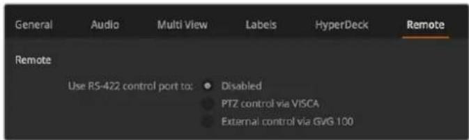
Set the RS-422 remote port to disabled, VISCA and GVG
Controlling Auxiliary Outputs
Auxiliary outputs are separate SDI outputs on some ATEM switcher models that can have various inputs and internal sources routed to them. They are very similar to router outputs and all video inputs, color generators, media players, program, preview and even color bars can be output. Most ATEM models provide for 1 - 6 auxiliary outputs.
TIP On ATEM Constellation 8K, dedicated auxiliary outputs are not required as any source can be routed to any output.
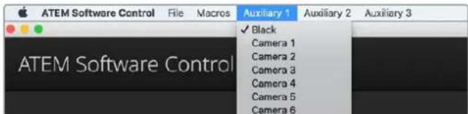
Auxiliary Outputs Control Menus on Mac
Routing Auxiliary Outputs
Each aux output has a menu for selecting the source to output on the aux video output. Simply select the menu, then scroll the list for the source you want to output. When selected, the output on the selected aux will change immediately. You can see the current source with a tick in the menu item. ATEM Constellation 8K has general purpose outputs instead of dedicated aux outputs, so ATEM Software Control provides an 'outputs' menu. This lets you select from 24 HD or Ultra HD outputs or six 8K outputs and then select the source you want routed to that output.
There is a range of sources available, including black, all video inputs, color bars, media players fill and media player key outputs, program, preview and clean feeds.
More information about Auxiliary outputs and how to use them is explained in the Using Auxiliary Outputs section. Aux outputs are extremely powerful and allow many exciting possibilities like alternative switcher outputs, or they are very commonly used for driving video projectors and video walls on stage during concerts and live performances. Most modern live performances have complex multi media aspects to them and the aux outputs are designed to allow you to control all these displays from your ATEM!
Program/Preview and A/B Direct Transition Control
When you first receive your ATEM switcher, it will be set to program/preview switching which is the current standard for an M/E switcher. You can change this preference to A/B Direct if you wish to use older style A/B switching. You'll find the 'transition control' options in the preferences window of ATEM Software Control.
Saving and Restoring Switcher Settings
ATEM Software Control lets you save and restore either specific settings, or all of the switcher settings you have created. This powerful feature is incredibly time saving on live productions where regular settings are used. For example, you can immediately restore saved camera settings, lower third graphics and detailed key setups from a laptop or USB drive.
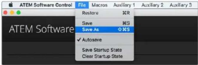
Saving settings menu.
Saving your Settings
1 Go to the menu bar in ATEM Software Control and select File>Save As.
2 A window will open asking for a file name and destination folder. After you have made your selection, click Save.
3 You'll now see the Save Switcher State panel containing checkboxes for all the available settings on each block of your ATEM switcher. The Select All checkbox is enabled by default. If you save with Select All enabled, ATEM Software Control saves your entire switcher settings. If you want to choose specific settings to save, you can deselect settings individually, or to remove all settings click Select All once to deselect them. Now you can select specific settings you want to save.
4 Click Save.
ATEM Software Control saves your settings as an XML file together with a folder for ATEM Media Pool contents.
After you have saved your settings you can quick save at any time by selecting File>Save, or by pressing Command S for Mac, or Ctrl S for Windows. Doing so will not overwrite your previous save, but will add a new XML file to your destination folder which is clearly identified with a time and date stamp. This means you can always restore a previous save if necessary.
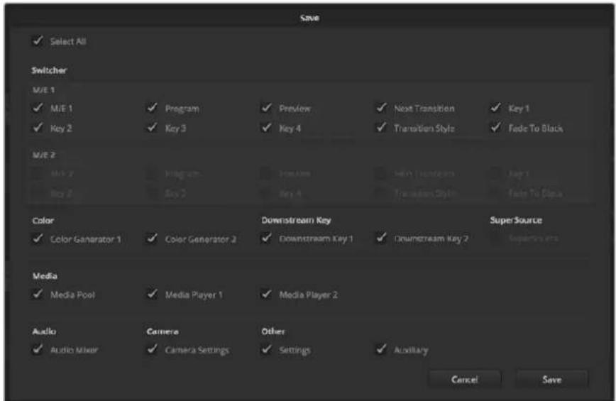
With ATEM Software Control you can save and restore all your switcher settings for your live production, including key settings, transition styles, media pool contents and more
Restoring your Settings
1 Go to the menu bar in ATEM Software Control and select File>Restore.
2 A window will ask for the file you want to open. Select your save file and click Open.
3 You'll now see a window containing active checkboxes for your saved settings on each block of your ATEM switcher. Leave Select All enabled to restore all your saved settings, or select only the checkboxes for the settings you want to restore.
4 Click Restore.
If your switcher settings are saved on a laptop, it's easy to take all your settings with you on location. Connect your laptop to any ATEM switcher and quickly restore your switcher settings.
Live production can be a busy and exciting time and you're always working in the moment, which means you can easily forget to back up your saved files when the production is over. If you have settings you want to keep, save them to your computer and an external drive, such as a USB drive. This means you can carry your settings with you and have a back up in case your settings are accidentally deleted on your computer.
Saving your Startup State
If you have your switcher set up the way you want it, you can easily save your entire switcher state as your default startup state. Go to the 'file' menu in ATEM Software Control and select 'save startup state'. Now whenever you restart your switcher, it will start up with your saved settings by default. If you want to clear the startup state and revert to the factory settings on restart, go to the 'file' menu and select 'clear startup state'.
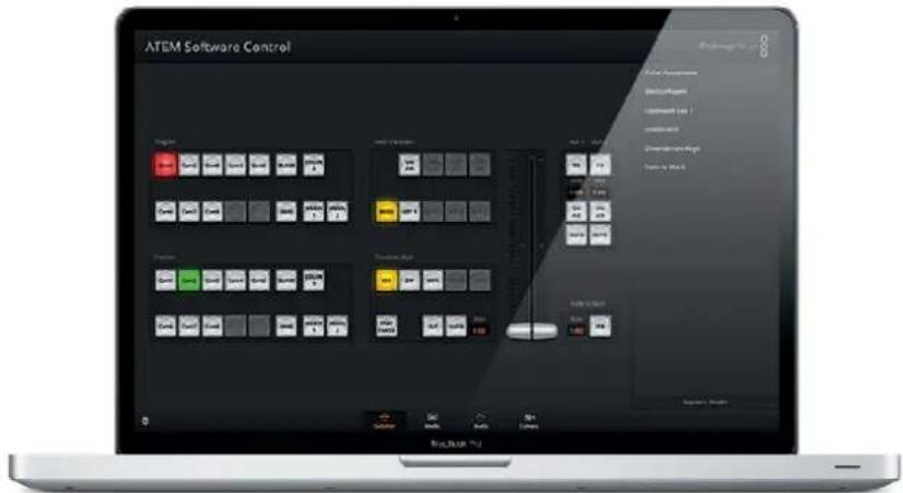
Saving your switcher settings on a laptop gives you the portability to restore your settings on any ATEM switcher. Saving to a USB drive means you can even carry your settings in your pocket.
Using Camera Control
Clicking on the 'camera' button in ATEM Software Control opens the camera control feature that lets you control Blackmagic Studio Cameras, Micro Studio Cameras, URSA Mini or URSA Broadcast from your ATEM switcher. Blackmagic camera settings such as iris, gain, focus, detail and zoom control are easily adjusted using compatible lenses, plus you can color balance cameras and create unique looks using the DaVinci Resolve primary color corrector that's built into the camera.
When controlling cameras, the ATEM switcher control works by broadcasting camera control packets via all the non down converted SDI outputs of your ATEM switcher. So this means you can connect an SDI output of your ATEM switcher to the camera's video inputs and the camera will detect the control packets in the SDI link and allow you to control features in the camera itself. You can control cameras via both regular SDI or optical fiber SDI connections when an optional SFP module is installed in a Blackmagic Studio Camera.
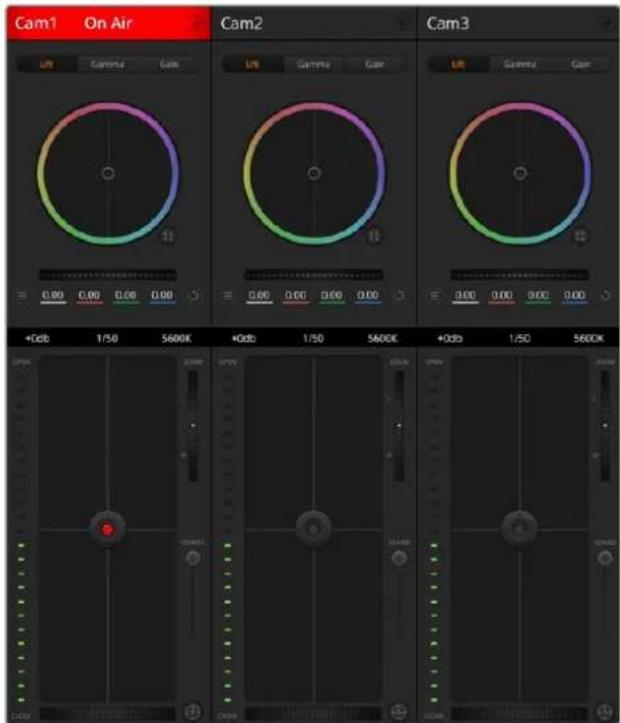
ATEM Camera Control.
Connecting via SDI
1 Connect your Blackmagic camera's SDI output to any SDI input on your ATEM switcher.
2 Connect any one of your ATEM switcher's SDI outputs, except down converted or multi view outputs, to your camera's program SDI input. Camera control signals are not sent via the multi view and down converted SDI outputs.
3 In your camera's settings, set the camera ID number to match your switcher input. For example, if studio camera 1 is connected to 'cam 1' on your ATEM switcher, the camera number in your camera settings must also be set to 1. This ensures tally is sent to the correct camera.
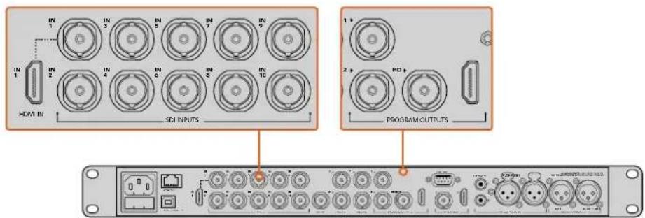
Connect a Blackmagic Studio Camera to any of your ATEM switcher's SDI inputs.
Connecting via Optical Fiber
1 Connect the Blackmagic Camera's optical out/in to the optical out/in on an ATEM Studio Converter or Talkback Converter 4K. You'll need to have SMPTE compatible optical fiber SFP modules installed in your Studio Camera and ATEM converter to connect via optical fiber.
2 Connect a suitable SDI out from your ATEM converter to any SDI input on your ATEM switcher.
3 Connect any one of your ATEM switcher's SDI outputs, except down converted or multi view outputs to your ATEM Converter's 'SDI in'. Camera control signals are not sent via the multi view and down converted SDI outputs.
4 On the Blackmagic camera, open the LCD menu and set the camera number to to match your switcher input. For example, if studio camera 1 is connected to 'cam 1' on your ATEM switcher, your camera number must also be set to 1. This ensures tally is sent to the correct camera.
Open ATEM Software Control preferences and set your switcher's button mapping to make sure you are switching the right camera with correct tally. With a video connection from your switcher to a Blackmagic camera, you can also get the advantage of live tally indicators, as well as the camera operators being able to view the program feed of your switcher by pressing the camera's 'pgm' button.
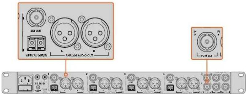
Connect multiple Blackmagic Studio Cameras via optical fiber using an ATEM Studio Converter. You'll need to have an optional SFP module installed in your Studio Camera to connect via optical fiber.
Camera Control Panel
Launch ATEM Software Control and click on the 'camera' button located at the bottom of the software window. You'll see a row of labeled Blackmagic camera controllers containing tools to adjust and refine each camera's image. The controllers are easy to use. Simply click the buttons using your mouse, or click and drag to adjust.
Click on the settings icon to select the aux output for camera control
Camera Control Selection
The button row at the top of the camera control page lets you select the camera number you would like to control. If you have more cameras that fit onto the window size, or you are running the color corrector window, then you can use these buttons to select between which camera you would like to control. If you are using an Aux output for monitoring your camera control, pushing these buttons to change the camera to control will also send that camera's video output to the Aux output setup in the switcher preferences.
Channel Status
The channel status at the top of each camera controller displays the camera label, On Air indicator and lock button. Press the lock button to lock all the controls for a specific camera. When on air, the channel status illuminates red and displays the On Air alert.
Camera Settings
The camera settings button near the bottom left of the master wheel lets you turn on the color bars feature in Blackmagic Studio Cameras, Micro Studio Cameras and URSA mini, plus adjust detail settings for each camera's picture signal.
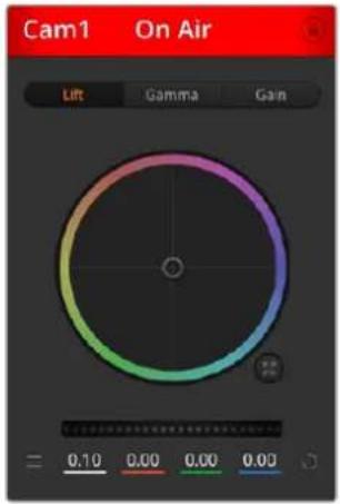
Each camera controller displays the channel status so you know which camera is on air. Use the color wheels to adjust each YRGB channel's lift, gamma and gain settings.
Show/Hide Color Bars
Blackmagic cameras have a color bars feature built in which you can turn on or off by selecting 'show' or 'hide' color bars. This feature can be very useful for visually identifying individual cameras while setting up for your live production. Color bars also provide an audio tone so you can easily check and set the audio levels from each camera.
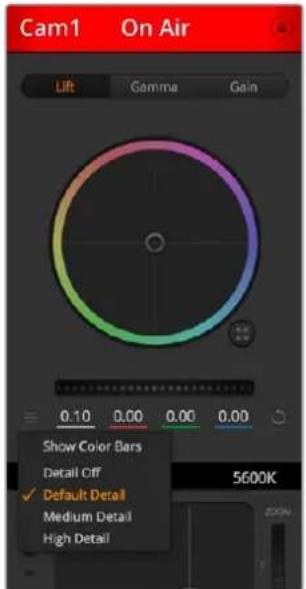
The camera settings button lets you turn color bars on or off and adjust the in-camera sharpening of connected Blackmagic cameras.
Detail
Use this setting to sharpen the image from your cameras live. Decrease or increase the level of sharpening by selecting: Detail off, detail default for low sharpening, medium detail and high detail.
Color Wheel
The color wheel is a powerful feature of the DaVinci Resolve color corrector and used to make color adjustments to each YRGB channel's lift, gamma and gain settings. You can select which setting to adjust by clicking on the three selection buttons above the color wheel.
Master Wheel
Use the master wheel below the color wheel to make contrast adjustments to all YRGB channels at once, or luminance only for each lift, gamma or gain setting.
Reset Buttons
The reset button near the bottom right of each camera controller lets you easily choose color correction settings to reset, copy or paste. Each color wheel also has its own reset button. Press to restore a setting to its default state, or copy/paste a setting. Locked controllers are not affected by the Paste feature.
The master reset button on the bottom right corner of the color corrector panel lets you reset lift, gamma and gain color wheels plus Contrast, Hue, Saturation and Lum Mix settings. You can paste color correction settings to camera controllers individually, or all cameras at once for a unified look. Iris, focus, coarse and pedestal settings are not affected by the Paste feature. When applying Paste to all, a warning message will appear asking you to confirm your action. This is so you don't accidentally paste new settings to any unlocked cameras that are currently on air.
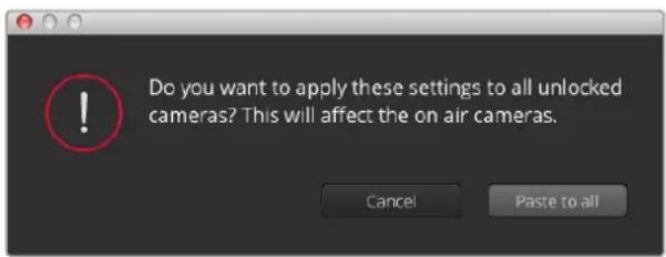
When applying 'paste to all', a warning message will appear asking you to confirm your action. This is so you don't accidentally paste new settings to any unlocked cameras that are currently on air.
Iris/Pedestal Control
The iris/pedestal control is located within the cross hairs of each camera controller. The control illuminates red when its camera is on air.
To open or close the iris, drag the control up or down. Holding the shift key allows only iris adjustments.
To darken or lift the pedestal, drag the control left or right. Holding the command key on a Mac, or the Control key on Windows, allows only pedestal adjustments.
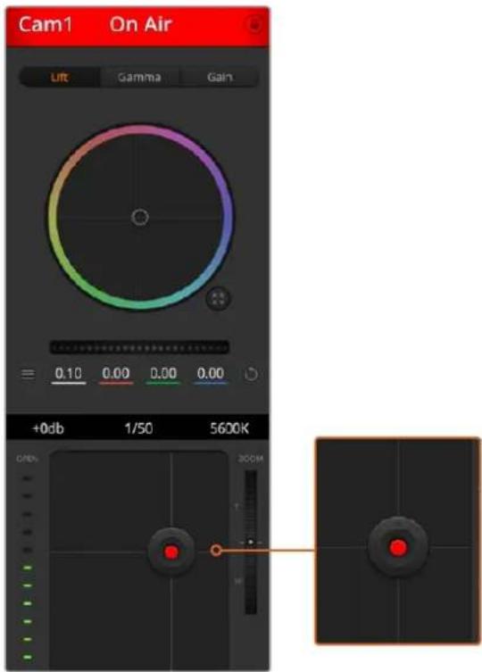
The iris/pedestal control illuminates red when its respective camera is on air.
Zoom Control
When using compatible lenses with an electronic zoom feature, you can zoom your lens in and out using the Zoom control. The controller works just like the zoom rocker on a lens, with telephoto on one end and wide angle on the other. Click on the zoom control, located above the Coarse slider and drag up to zoom in, or drag down to zoom out.
Coarse Setting
The coarse setting is located to the right of the iris/pedestal control and is used to limit the iris range. This feature helps you prevent over exposed images from going to air.
To set your coarse threshold, completely open the iris using the iris control, then drag the coarse setting up or down to set optimum exposure. Now when you adjust the iris, the coarse threshold will prevent it from going above optimum exposure.
Iris Indicator
The iris indicator is located to the left of the iris/pedestal control and displays a visual reference so you can easily see how open or closed the lens aperture is. The iris indicator is affected by the coarse setting.
Auto Focus Button
The auto focus button is located at the bottom right corner of each camera controller. Press to automatically set the focus when you have an active lens that supports electronic focus adjustments. It's important to know that while most lenses support electronic focus, some lenses can be set to manual or auto focus modes and so you need to ensure your lens is set to auto focus mode. Sometimes this is set by sliding the focus ring on the lens forward or backward.
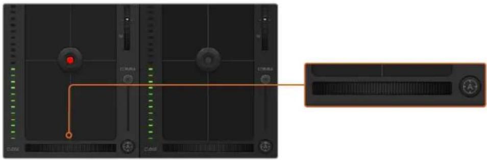
natural_image
Close-up of a CD or audio workstation interface showing track controls and playback buttons (no readable text or symbols)Click on the auto focus button or drag the manual focus adjustment left or right to focus a compatible lens.
Manual Focus Adjustment
When you want to adjust the focus on your camera manually, you can use the focus adjustment located at the bottom of each camera controller. Drag the wheel control left or right to manually adjust focus while viewing the video feed from the camera to ensure your image is nice and sharp.
Camera Gain
The camera gain setting allows you to turn on additional gain in the camera. This is important when you are operating in low light conditions and need extra gain in the front end of the camera to avoid your images being under exposed. You can decrease or increase gain by clicking on the left or right arrows on the dB gain setting.
You can turn on some gain when you need it, such as outdoor shoots when the light fades at sunset and you need to increase your image brightness. It's worth noting that adding gain will increase noise in your images.
Shutter Speed Control
The shutter speed control is located in the section between the color wheel and the iris/pedestal control. Decrease or increase the shutter speed by hovering your mouse pointer over the shutter speed indicator and then clicking on the left or right arrows.
If you see flicker in lights you can decrease your shutter speed to eliminate it.
Decreasing shutter speed is a good way to brighten your images without using camera gain because you are increasing the exposure time of the image sensor. Increasing shutter speed will reduce motion blur so can be used when you want action shots to be sharp and clean with minimal motion blur.
White Balance
The white balance setting next to the shutter speed control can be adjusted by clicking on the left or right arrows on each side of the color temperature indicator. Different light sources emit warm or cool colors, so you can compensate by adjusting the white balance. This ensures the whites in your image stay white.
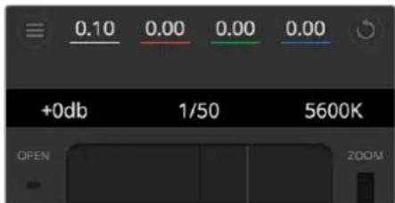
Hovering your mouse pointer over the gain, shutter speed and white balance indicators reveal arrows you can click on to adjust their respective settings.
DaVinci Resolve Primary Color Corrector
If you have a color correction background, then you can change your camera control from a switcher style CCU interface to a user interface that's more like a primary color corrector on a post production color grading system.
Blackmagic cameras feature a DaVinci Resolve primary color corrector built in. If you have used DaVinci Resolve, then creatively, grading in the Blackmagic camera will be identical so you can use your color grading experience for live production. The color corrector panel can be expanded out of any camera controller and provides expanded color correction control with extra settings and a full primary color corrector interface.
You have color wheels and settings such as saturation available and you can see shadows, mid tones and highlight settings all at the same time. Simply switch between cameras using the camera selection controls at the top of the window as you need.
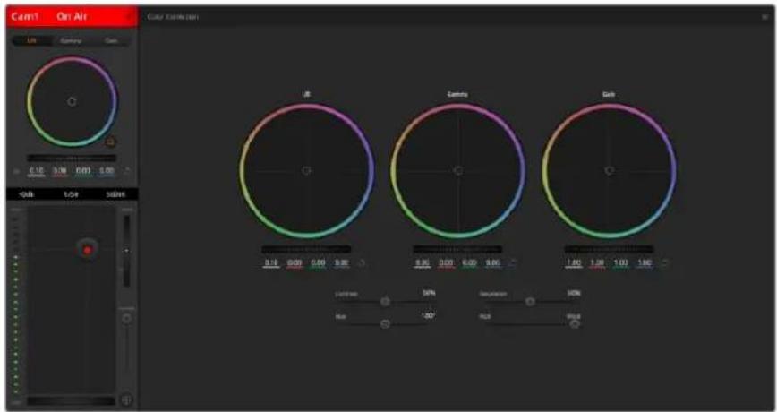
Click on the DaVinci Resolve primary color corrector button to expand the color correction window and adjust settings.
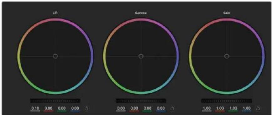
radar
| Metric | Value | | -------- | ----- | | Lift | 0.10 | | Gerome | 0.00 | | Gain | 1.00 |Lift, gamma and gain color wheels in the color corrector panel.
Color Wheels
Click and drag anywhere within the color ring
Note that you don't need to drag the color balance indicator itself. As the color balance indicator moves, the RGB parameters underneath change to reflect the adjustments being made to each channel.
Shift-Click and drag within the color ring
Jumps the color balance indicator to the absolute position of the pointer, letting you make faster and more extreme adjustments.
Double-click within the color ring
Resets the color adjustment without resetting the master wheel adjustment for that control.
Click the reset control at the upper-right of a color ring
Resets both the color balance control and its corresponding master wheel.
Master Wheels
Use the master wheels below the color wheels to adjust each YRGB channels' lift, gamma and gain controls.
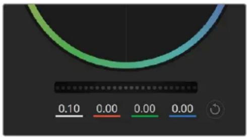
Adjust the master wheels by dragging the wheel control left or right.
To make adjustments using the master wheel:
Drag the master wheel left or right
Dragging to the left darkens the selected parameter of the image, dragging to the right lightens that parameter. As you make an adjustment, the YRGB parameters underneath change to reflect the adjustment you're making. To make a Y-only adjustment, hold down the ALT or Command key and drag left or right. Because the color corrector uses YRGB processing, you can get quite creative and create unique affects by adjusting the Y channel only. Y channel adjustments work best when the Lum Mix setting is set to the right side to use YRGB processing vs the left side to use regular RGB processing. Normally, most DaVinci Resolve colorists use the YRGB color corrector as you get a lot more control of color balance without affecting overall gain, so you spend less time getting the look you want.
Contrast Setting
The Contrast setting gives you control over the distance between the darkest and lightest values of an image. The effect is similar to making opposing adjustments using the lift and gain master wheels. The default setting is 50%.
Saturation Setting
The Saturation setting increases or decreases the amount of color in the image. The default setting is 50%.
Hue Setting
The Hue setting rotates all hues of the image around the full perimeter of the color wheel. The default setting of 180 degrees shows the original distribution of hues. Raising or lowering this value rotates all hues forward or backward along the hue distribution as seen on a color wheel.
Lum Mix Setting
The color corrector built into Blackmagic cameras is based on the DaVinci Resolve primary color corrector. DaVinci has been building color correctors since the early 1980's and most Hollywood films are color graded on DaVinci Resolve than any other method.
This means that your color corrector built into the camera has some unique and creatively powerful features. The YRGB processing is one of those features.
When color grading, you can choose to use RGB processing, or YRGB processing. High end colorists use YRGB processing because you have more precise control over color and you can independently adjust the channels with better separation and more creative options.
When the Lum Mix control is set to the right side, you have the 100% output of the YRGB color corrector. When you have the Lum Mix control set to the left side, you get 100% output of the RGB corrector. You can set the Lum Mix to any position between the left and right to get a blend of output from both the RGB and YRGB correctors.
Which is the correct setting to use? That's up to you, as color correction is a pure creative process and there is no right and wrong. The best setting is what you like the most and what you think looks good!
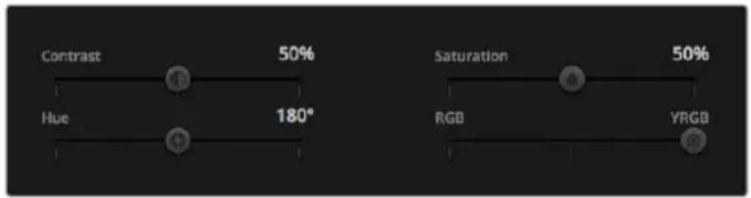
Drag the sliders left or right to adjust Contrast, Saturation, Hue and Lum Mix settings.
Synchronizing Settings
When connected, camera control signals are sent from your ATEM switcher to the Blackmagic camera. If a setting is accidentally adjusted from your camera, camera control will automatically reset that setting to maintain synchronization.
Using a DaVinci Resolve Micro Panel
The DaVinci Resolve primary color corrector in each camera controller can be controlled using a DaVinci Resolve Micro panel. This lets you make fast and precise color adjustments using a hardware control panel.
TIP For the DaVinci Resolve Micro Panel to communicate with your ATEM switcher, make sure you have installed DaVinci Resolve 12.5.5 or later and ATEM switchers 7.1 or later.
To set up a DaVinci Resolve Micro Panel with your ATEM switcher
1 Connect the DaVinci Resolve Micro Panel to your computer via USB-C and launch ATEM Software Control.
2 Click on the 'camera' tab and select a camera by clicking anywhere in the desired camera controller.
3 On the DaVinci Resolve Micro Panel, rotate the trackballs and turn the knobs to adjust the corresponding controls in the primary color corrector.
Making Color Correction Adjustments
The DaVinci Resolve Micro panel is primarily designed for use with DaVinci Resolve software, but you can also use it to make adjustments in the color corrector panel of ATEM Software Control in the following way:
The Trackballs
The three trackballs control the lift, gamma and gain color wheels in the color corrector panel. The ring surrounding each trackball adjusts the corresponding master wheels beneath the color wheels.
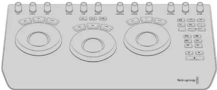
DaVinci Resolve Micro Panel
Control Knobs
As you change settings with the hardware panel, you will see the corresponding settings on the software panel change as well. Use the following control knobs to make adjustments.
| Y Lift | Allows you to modify image contrast via a Y-only adjustment for the black level. |
| Y Gamma | Allows you to modify image contrast via a Y-only adjustment for gamma. |
| Y Gain | Allows you to modify image contrast via a Y-only adjustment for highlights. |
| Contrast | Rotate clockwise to increase contrast and counterclockwise to reduce contrast. |
| Highlights | The ‘highlights’ knob controls the iris on your selected camera. Rotate the knob clockwise to open the iris and counterclockwise to close. |
| Saturation | Rotate clockwise or counterclockwise to increase or decrease color saturation. |
| Hue | Adjust the hue along the hue distribution as seen on a color wheel by rotating the ‘hue’ knob clockwise or counterclockwise. |
| Lum Mix | Rotate clockwise or counterclockwise to set the output blend between the RGB and YRGB correctors. |
Control Buttons
| Left Arrow | Select the previous camera number |
| Right Arrow | Select the next camera number |
For more information on how each control affects the image, refer to the details provided earlier in this section.
HyperDeck Control
Introducing HyperDeck Control
If you are running ATEM Switchers software 6.8 or newer, you can connect up to 4 Blackmagic HyperDeck Studio disk recorders to your switcher and control them using the HyperDecks palette in ATEM Software Control, or from the system control buttons on an ATEM broadcast panel. This is a very powerful feature! With four HyperDecks connected to your switcher, it's like having a portable videotape department able to record outputs from your switcher, play back graphics, or you can even set your switcher to roll prerecorded segments at the press of a button!
Transport controls are located in the HyperDecks palette in ATEM Software Control, or in the system control menu on an ATEM broadcast panel, which lets you play back video, jog and shuttle, skip clips, pause and more. You can also record video.
When you combine this feature with ATEM's powerful macros feature, it opens up a world of creative possibilities that can really enhance your live production!
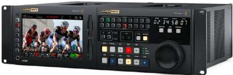
HyperDeck Extreme Control and HyperDeck Extreme 8K HDR
Connecting HyperDecks
Connecting Blackmagic HyperDecks to your switcher is very similar to connecting cameras and other video sources via your switcher's SDI or HDMI inputs. The only additional connection is Ethernet which lets your ATEM switcher communicate with the HyperDeck disk recorder.
1 Make sure your ATEM switcher and broadcast panel software are updated to version 6.8 or newer and your HyperDeck disk recorder is running HyperDeck software 4.3 or newer.
2 Using the Ethernet connector, connect your HyperDeck disk recorder to the same network your ATEM switcher is connected to.
3 Press the remote button marked 'REM' on the HyperDeck's control panel. The 'REM' button will illuminate which means the HyperDeck has remote control enabled.
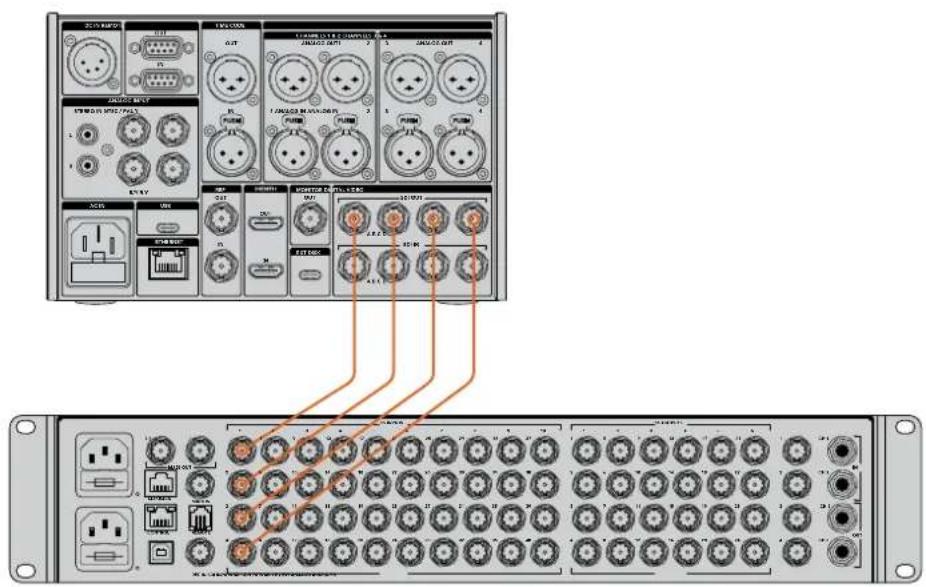
Plugging the 8K quad link SDI output of a Hyperdeck Extreme 8K HDR into the SDI input of an ATEM Constellation 8K.
4 Plug the SDI or HDMI output of your HyperDeck into the SDI inputs of your ATEM switcher, or the HDMI inputs if available. If you are using quad link SDI, it's important to connect each input and output in the correct order.
5 If you want to record your ATEM switcher's program output with your HyperDeck, plug one of the switcher's SDI auxiliary outputs into the SDI input of your HyperDeck. With ATEM Constellation 8K, you can connect any SDI output to the SDI input of your HyperDeck.
6 Repeat the process for each HyperDeck you want to connect.
Now all you have to do is tell your ATEM software or ATEM broadcast panel which input and IP address each HyperDeck is using. You can do this in the HyperDeck tab in ATEM Software Control switcher settings, or using the system control soft buttons on an ATEM broadcast panel.
HyperDeck Settings
HyperDeck connection settings are located in the 'HyperDeck' tab of the ATEM Software Control switcher settings. Here you'll see setup options for up to four HyperDecks.
Entering the necessary details is as easy as typing in your HyperDeck's IP address in the 'IP Address' box and choosing the source it's plugged into from the 'input' dropdown menu. Click 'connect' and your HyperDeck is ready to be controlled.
Status indicators appear above and below each HyperDeck icon to let you know the connection status. A green tick means your HyperDeck is connected, in remote and ready to go.
If your HyperDeck is connected and recognized, but does not have its remote button enabled, you will see an indicator letting you know remote is not active.
If your HyperDeck is not recognized, you will see a 'failed to connect' indicator. If you see this indicator, check the HyperDeck's Ethernet port is connected to your network and the IP address is entered correctly.
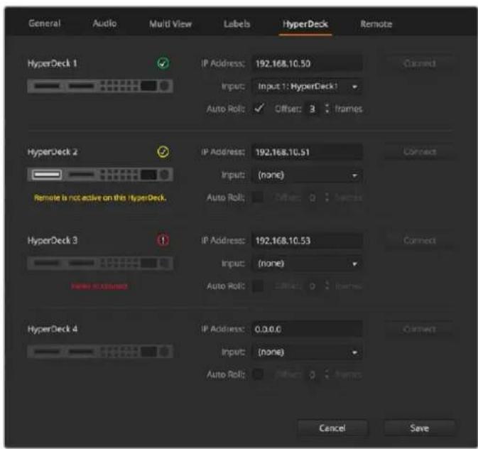
Auto Roll
You can set a HyperDeck disk recorder to automatically roll video when it is switched to the program output. For example, you can cue a HyperDeck to the point you want your source to begin, then roll the source by pressing its input button on the mix effects program row.

As HyperDecks must buffer a couple of frames before commencing playback, the actual cut will be delayed a preset number of frames to ensure a clean transition. This is just like setting a preroll on a videotape machine. You can adjust the length of this delay by changing the number in the 'offset' box. We've found that five frames usually ensures a clean cut.
If you want to cue to a still frame of video or manually trigger video playback on your HyperDeck, you can also deselect the 'auto roll' feature.
Controlling HyperDecks with ATEM Software Control
To control the HyperDecks connected to your switcher, click the 'media players' tab in the software control panel and choose the 'HyperDecks' palette.
Here you can choose between each of the HyperDecks connected to your system by clicking one of the four buttons along the top of the panel. These are named according to the labels entered in ATEM settings. Available HyperDecks are shown with white text, while the HyperDeck you are currently controlling is shown in orange.
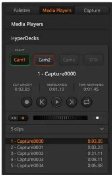
Choose from up to four HyperDecks by clicking their selection buttons in the HyperDecks palette.
In addition to the text color, each HyperDeck's selection button also has a tally indicator.
| Green Outline Indicates a HyperDeck that is currently switched to the preview output. | |
| Red Outline | Indicates a HyperDeck that is currently switched to the program output, meaning it is currently live to air. You may also see one of the following status indicators above the selection buttons for your HyperDecks. |
| Ready | HyperDeck is set to remote and a disk is inserted. It is ready for playback and recording if space is available. |
| Record HyperDeck is currently recording. | |
| No Disk HyperDeck has no disk inserted. | |
| Local | HyperDeck is not set to 'remote' and cannot currently be controlled by your ATEM switcher. |
| Hue | Adjust the hue along the hue distribution as seen on a color wheel by rotating the 'hue' knob clockwise or counterclockwise. |
| Lum Mix | Rotate clockwise or counterclockwise to set the output blend between the RGB and YRGB correctors. |
When you select a HyperDeck, you'll see information about the currently selected clip such as the name and length, as well as time elapsed and time remaining. Below this you'll see the control buttons.
 | RecordClick on this button to start recording on your HyperDeck. Click again to stop recording. |
 | Previous ClipMoves to the previous clip in your HyperDeck's media list. |
 | PlayClicking 'play' once initiates playback, clicking it again stops playback. If you have 'auto roll' enabled in your HyperDeck settings, playback will commence automatically when your HyperDeck is switched to the program output. |
 | Next ClipMoves to the next clip in your HyperDeck's media list. |
 | LoopClick 'loop' once to loop the currently selected clip and again to loop all of the clips in your HyperDeck's media list. |
To move through a clip use the shuttle/jog slider underneath your HyperDeck's control buttons. This lets you move quickly, or shuttle through a selected clip, or jog frame by frame. You can switch between these modes with the buttons next to the shuttle/jog slider.

natural_image
User interface control bar with playback and scroll icons (no text or symbols)Choose between shuttle and jog transport controls with the buttons to the left of the transport slider. Adjust the slider left and right to move forward or backwards through your clip.
The clip list below the transport control shows all of the clips currently available on the selected HyperDeck. You can expand or collapse the list by pressing the arrow to the right of the clip list.
Playback
Playing media on your Hyperdeck is easy. Switch your HyperDeck to the preview output and select the clip you want to show. Use the transport controls to cue to the preferred point in your clip. When you switch your HyperDeck to program output, the 'auto roll' feature will automatically start playback from this point.
If you want to manually trigger the playback, for example holding on a still frame then rolling, disable the respective HyperDeck's auto roll checkbox in the 'HyperDeck' tab in ATEM software's 'settings' menu.
Recording
To record to a HyperDeck with a formatted disk inserted, press the 'record' button in the HyperDeck palette transport controls. The 'time remaining' indicator in the HyperDeck palette will let you know the approximate recording time remaining in the SSD.
Controlling HyperDecks with ATEM Hardware Panels
If you are using an ATEM hardware panel, you can control any connected HyperDecks using the hardware panel. Once you have connected your HyperDecks to your switcher as described in the 'connecting HyperDecks' section, you can use the system control buttons and LED menu on your panel to set up and control each HyperDeck.
HyperDeck Setup with ATEM Broadcast Panels
Please follow the steps in this section to set up your HyperDeck with an ATEM Broadcast Panel.
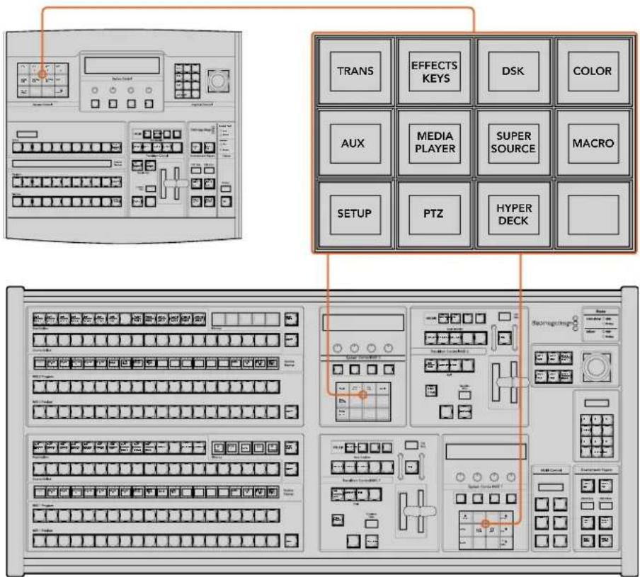
System Control on ATEM 1 M/E Broadcast Panel (top) and ATEM 2 M/E Broadcast Panel (bottom)
1 Press the 'HyperDeck setup' soft button to access the HyperDeck setup menu.
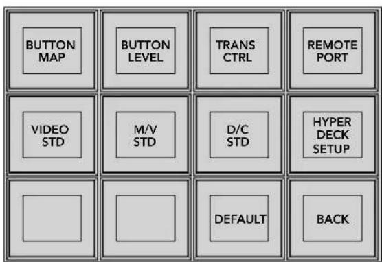
To access the HyperDeck setup menu press the 'hyper deck setup' button in the system control setup menu.
2 Press one of the four numbered 'HyperDeck' soft buttons along the top row of the HyperDeck setup menu to specify which HyperDeck you are setting up.
3 Press the 'Input' soft button to let your broadcast panel know that you are about to specify which source corresponds to your HyperDeck.
4 Press the source button that matches the input that you have connected your HyperDeck to or scroll through your source list using the third control knob under the LED display. Press the 'save' soft button to confirm your selection.
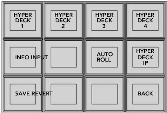
Use the HyperDeck setup menu to configure connected HyperDecks
5 Once you have specified the source for a given HyperDeck, you will need to set its IP address. To do this, press the 'HyperDeck IP' soft button in the HyperDeck setup menu. This will bring up an IP address on your broadcast panel's four line display.
6 Match this IP address to your HyperDeck's IP address by scrolling through each value with the control knob directly under it, or selecting that value with the corresponding soft button under its control knob and entering the details with your broadcast panel's Number Pad. Once you have finished entering each value, press the soft button under its 'set' title in the system control LED display to confirm that digit.
7 Once you have entered the entire IP address, press the 'save' soft button in the system control 'HyperDeck Setup' menu to confirm your settings.
Your HyperDeck should now be correctly configured. You can check its status by pressing the 'Info' soft button in your ATEM broadcast panel's HyperDeck setup menu. This will display the IP address, the HyperDeck's status and whether it is set to 'remote' operation. Your HyperDeck must be set to 'remote' for you to control it via the broadcast panel.
To set up additional HyperDecks, select the HyperDeck you want to configure in the HyperDeck setup menu and repeat this procedure for each disk recorder you have connected.
Auto Roll
You can also toggle your HyperDeck's auto roll function from the 'HyperDeck Setup' menu in System Control.
The auto roll feature lets you set a HyperDeck disk recorder to automatically roll video when it is switched to the program output. For example, you can cue a HyperDeck to the point you want your source to begin, then roll the source by pressing its input button on the mix effects program row.
As HyperDecks must buffer a couple of frames before commencing playback, the actual cut will be delayed a preset number of frames to ensure a clean transition. This is just like setting a preroll on a videotape machine. You can adjust the length of this delay by changing the number in the 'offset' box. We've found that five frames usually ensures a clean cut.
If you want to cue to a still frame of video or manually trigger video playback on your HyperDeck, you can also deselect the 'auto roll' feature.
Configuring auto roll:
1 Press the 'auto roll' soft button in the HyperDeck Setup system control menu.
2 Toggle auto roll on and off by pressing the soft button under the 'auto roll' title in the four line display.
3 When auto roll is enabled, set the number of offset frames by turning the third control knob under the four line display.
4 Confirm your settings with the 'save' soft button
If you want to cue to a still frame or manually trigger video playback on your HyperDeck, you can disable the 'auto roll' feature on each HyperDeck.
Controlling HyperDecks with ATEM Broadcast Panels
To control a given HyperDeck, press the 'HyperDeck' soft button in the system control 'home' menu and select the HyperDeck you wish to control from top row of the menu.
The system control panel LED display will provide information on which HyperDeck is connected, the currently selected clip and the time remaining, or time elapsed, on the current clip. You can toggle between time elapsed and time remaining by pressing the soft button under the fourth control knob under the LED display.
If your HyperDeck is properly connected and has a disk inserted, you will see two rows of control buttons on the second and third rows of the HyperDeck menu. These are labelled according to their function and control is very intuitive.
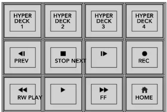
Use the HyperDeck control menu to select and control HyperDeck disk recorders
Use the 'prev' and 'next' buttons, the rotary knob under the 'clip' heading in the LED display, or the number pad in conjunction with the soft button under the 'clip' title in the LED display to move between clips. The 'play,' 'stop,' 'record,' 'fast forward' and 'reverse' buttons can be used just as you would on a VTR. When a clip is already playing, pressing the 'play' button again will loop that clip, or loop all of your HyperDeck's media if 'play all' is selected.
You can also shuttle and jog the clips on your HyperDeck by turning the control knobs under the 'shuttle' and 'jog' titles in the system control LED display. Just note that you will first need to press the 'shuttle' or 'jog' knob's corresponding soft button to enable these controls; this is to ensure that you don't accidentally shuttle through a clip while it is live to air.
You can modify the function of some HyperDeck controls with the 'shift' button on your broadcast panel. When this is pressed, the 'play' button on your HyperDeck control menu becomes 'play all.' This will play all of the clips on your HyperDeck disk recorder, starting with the currently selected clip.
HyperDeck Multi Control on ATEM 2 M/E Broadcast Panels
For quick access, you can also assign one of your HyperDeck disk recorders to your ATEM 2 M/E Broadcast Panel's multi control.
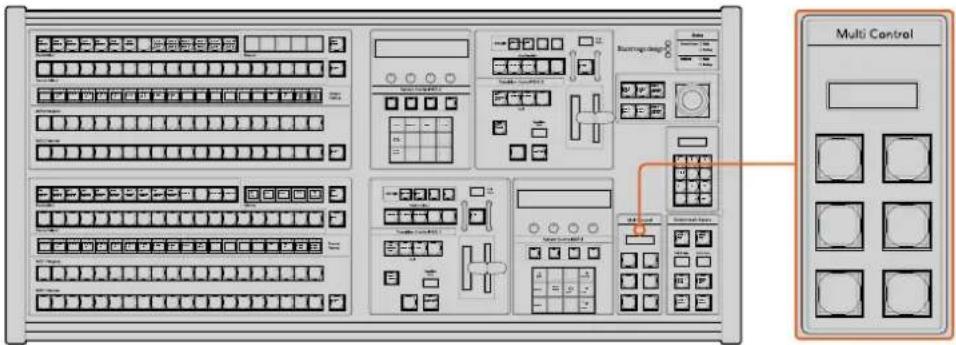
Multi Control Buttons
To do this, hold down the 'shift button' on your panel and press the soft button for one of your HyperDeck disk recorders in the system control HyperDeck menu. That HyperDeck will then be linked to your multi control menu and you will be able to control it without having to access the HyperDeck system control menu.
The multi control menu will display the short name of your HyperDeck as well as the current clip number. The soft buttons on your multi control will correspond to the following functions.
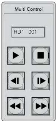
The Multi Control panel can provide quick HyperDeck control. Key labels are for illustration purposes only
These buttons have exactly the same functions as they do in the HyperDeck controls detailed on the previous page. Please note that as the multi control does not have context sensitive soft buttons, you will not see the icons shown in the illustration on your ATEM 2 M/E Broadcast Panel. We recommend applying sticky labels to your multi control keys for their assigned functions.
You can access additional features through multi control by using the following key combinations.
| Shift+stop | Record |
| Press Play twice | Play all |
| Shift + play | Loop one (or loop all if you are playing all) |
HyperDeck Setup with ATEM 1 M/E Advanced Panel
Once you have connected your HyperDeck to your switcher, as detailed in the 'connecting HyperDecks' section, use ATEM 1 M/E Advanced Panel's system control and LCD soft buttons to setup and control your HyperDecks.
To begin, press the system control 'settings' button.
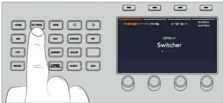
You'll notice that ATEM 1 M/E Advanced Panel displays four setup options along to top of the LCD screen. These include 'switcher,' 'panel,' 'HyperDecks,' and 'button mapping.' Each corresponds to a setup menu. Press the LCD soft button above 'HyperDecks' to enter the 'HyperDeck settings' menu.
The HyperDeck settings menu has three pages, which you can select using the 'left' and 'right' arrow buttons in the system control panel, or by pressing the '1,' '2,' and '3' buttons on your ATEM 1 M/E Advanced Panel's numerical keypad.
Assigning an input to a HyperDeck
In the first menu page, you'll see the 'HyperDeck' indicator in the bottom left corner and an 'input' indicator.
Use the control knob under the 'HyperDeck' indicator to cycle through the available HyperDecks.
Once you have selected a HyperDeck, rotate the knob under the 'input' indicator to select which input that HyperDeck is connected to on your switcher. For example, if HyperDeck 1 is connected to SDI In 4 on your switcher, rotate the knob under the 'input' indicator to select 'camera 4.' Press the 'input' knob to confirm your selection.
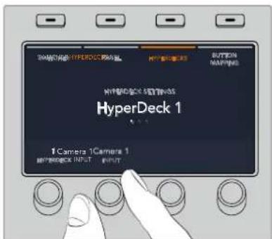
Repeat this process for any additional HyperDecks you have connected to your switcher by assigning inputs to HyperDeck slots 1, 2, 3 and 4, if required.
Assigning an IP Address
Once you've assigned an input to a HyperDeck, you'll need to enter its IP address. This allows ATEM 1 M/E Advanced Panel to control the HyperDeck via Ethernet.
To enter a HyperDeck's IP address, navigate to the third HyperDeck settings page with the 'left' or 'right' arrow buttons, or pressing '3' on the numeric keypad while in the HyperDeck settings menu.
In this page, you'll see an IP address for the currently selected HyperDeck. Each IP address number corresponds to a rotary knob below it. To change these numbers, you can rotate the corresponding knob, or press the knob once and enter a number using the numeric keypad. Do this for each number in the IP address.
Once you've entered the IP address for your HyperDeck, press the soft button corresponding to the 'save changes' indicator to confirm the address. To cancel, press 'undo'.
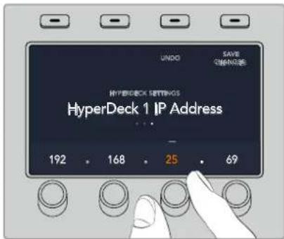
To enter the IP address for subsequent HyperDecks, you'll need to select the HyperDeck using the first page of the HyperDeck settings menu.
Auto Roll
You can toggle your HyperDeck's auto roll function from the second screen of the HyperDeck settings menu. While in the HyperDeck settings menu, use the 'left' or 'right' arrow buttons in the system control panel to navigate to this screen.
While in this menu, press the LCD soft button above the 'auto roll' indicator to turn the auto roll feature on. The indicator text will illuminate blue when auto roll is on.
The auto roll feature lets you set a HyperDeck disk recorder to automatically roll video when it is switched to the program output. For example, you can cue a HyperDeck to the point you want your source to begin, then roll the clip by pressing the HyperDeck's input button on the program row.
As HyperDecks must buffer a couple of frames before commencing playback, the actual cut will be delayed a preset number of frames to ensure a clean transition. This is just like setting a preroll on a videotape machine. You can adjust the length of this delay by changing the 'offset' frames number using the control knob under this indicator. Press the soft button above the 'save changes' indicator to confirm your change.
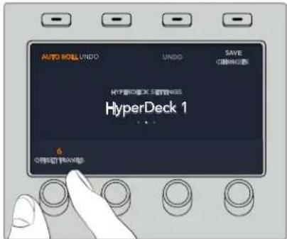
Controlling HyperDecks with ATEM 1 M/E Advanced Panel
HyperDeck controls are available in the 'media players' menu in your ATEM 1 M/E Advanced Panel. To access this menu, press the 'media players' control panel button and press the soft button above the 'HyperDecks' indicator to access HyperDeck control. If your switcher has more than two media players, you may need to navigate to the next menu page to access HyperDeck controls.
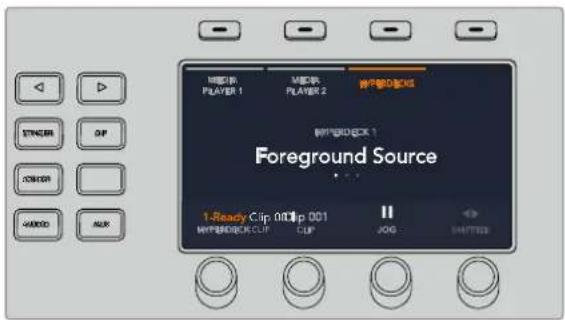
You can now use the rotating knobs below the 'hyperdeck,' 'clip,' 'jog' and 'shuttle' indicators to select HyperDecks, select clips and jog and shuttle these clips.
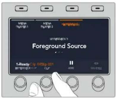
The text in the center of the HyperDeck control menu will change to reflect the HyperDeck and clip that you have selected.
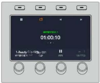
Use the third and fourth pages of the 'media players' LCD menu for more HyperDeck controls, including play, stop, loop playback and forward and reverse skip for moving between clips.
TIP To play all clips, hold down the shift button and press the 'play' soft button.
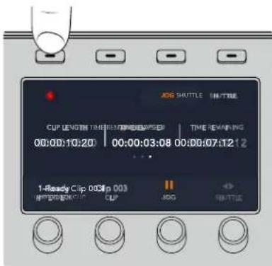
In the fourth menu page, press the 'record' button to record the program output of your switcher to your HyperDeck. Use the 'jog' and 'shuttle' commands to scrub through recorded footage.
Using ATEM Hardware Panels
ATEM hardware panels are 'hands on' control panels for ATEM switchers that plug into your switcher using an Ethernet connection. The keyboard has similar functions to the software panel and the main buttons are laid out in a similar ME style, so it's easy to move between the hardware and software interfaces.
If fast and critical live switching is being done, then the ATEM hardware panel is an incredibly fast and robust control solution. There's nothing like pushing high quality buttons on a panel to ensure fast and accurate switching!
When using a hardware broadcast panel and the software panels together, any change on one panel will be reflected on the other and you can use both panels at the same time. You can also plug in more than one hardware panel if you need a more advanced solution.
This section shows how to use the different ATEM panels that are available should you need a hardware panel for your live production.
ATEM 1 M/E Advanced Panel
The ATEM 1 M/E Advanced Panel provides all the features of the ATEM 1 M/E Broadcast Panel, but with advanced CCU control and the ability to control up to 4 M/Es from the one panel. System control is generally faster and more convenient using a centralized LCD menu with soft buttons and controls.
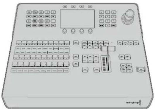
natural_image
Front view of a control panel with buttons, display screen, and keyboard (no visible text or labels)ATEM 1 M/E Broadcast Panel
The ATEM 1 M/E Broadcast Panel is designed for switchers with one mix effects panel, or if you need a hardware panel to control a mix effects panel on a larger ATEM switcher with more than one ME.
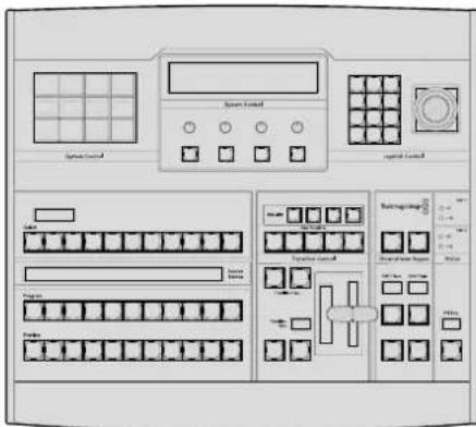
ATEM 2 M/E Broadcast Panel
This hardware control panel is designed to control two mix effects panels individually. The panel can control two single ATEM switchers with one mix effects panel, such as ATEM Television Studio models, or one of the larger ATEM Production Studio or Broadcast Studio switchers that have 2 mix effects panels.
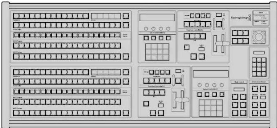
Using the ATEM 1 M/E Advanced Panel
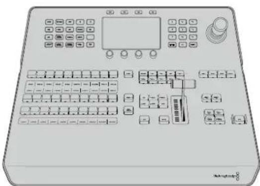
natural_image
Front view of a medical or laboratory instrument with control panel, buttons, and display (no visible text or symbols)Using the Control Panel
Mix Effects
The program bus, preview bus and source names display are used together to switch sources on the program and preview outputs.
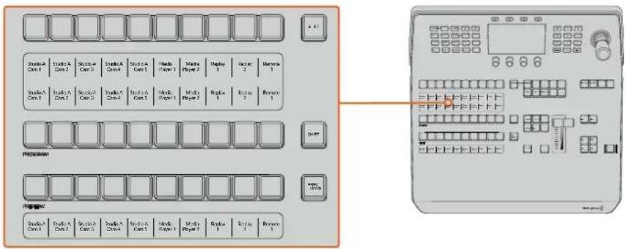
ATEM Mix Effects
Source Name Displays
The source name displays use labels to represent the switcher's external inputs or internal sources. Labels for the external inputs can be edited on the settings window of the software control panel. Labels for the internal sources are fixed and don't need to be changed.
The displays show the labels for each row of button in the source select row, program row and preview row.
Pressing the SHIFT button will change the source names display to show extra sources, called shifted sources, allowing selection of up to 20 different sources.
Simultaneously pressing both SHIFT buttons next to the source select and program rows will change the source names display to show protected sources and these are available in the source select row for keyers and routing to auxiliary outputs. Protected sources are program, preview, clean feed 1 and clean feed 2.
Program Bus
The program bus is used to hot switch background sources to the program output. The source currently on air is indicated by a button that is illuminated red. A blinking red button indicates that the shifted source is on air. Pressing the SHIFT button will display the shifted source.
Preview Bus
The preview bus is used to select a source on the preview output. This source is sent to program when the next transition occurs. The selected source is indicated by a button that is illuminated green. A blinking green button indicates that a shifted source is on preview. Pressing the SHIFT button will display the shifted source.
SHIFT
The SHIFT button provides a global shift and is used to shift the program, preview and select busses along with the label. It also provides a shift for the transition type and joystick and other menu functions.
Double-pressing buttons in the preview and select busses, as well as the transition type buttons, is the same as shift-selecting them and can be a faster way to shift-select buttons. Double-pressing is not implemented for the program bus as it would cause the program output to momentarily show the wrong source.
Source Select Bus
The source select bus works in conjunction with the source names display and is used to assign sources to auxiliary outputs and keyers. When the macro button is enabled, this row of buttons is also used for loading and running macros recorded to the corresponding slots. The buttons will illuminate blue when the macro button is enabled.
The destination display and select bus together show you the routing of sources to keys and auxiliary outputs. The currently selected source is indicated by an illuminated button. A blinking button indicates a shifted source. A green illuminated button identifies a protected source. Protected sources are program, preview, clean feed 1 and clean feed 2.
Transition Control and Upstream Keyers
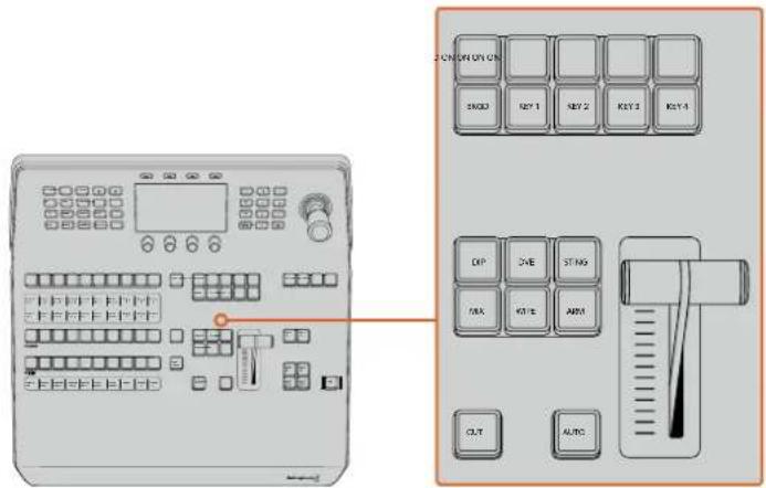
Transition Control and Upstream Keyers
CUT
The CUT button performs an immediate transition of the Program and Preview outputs, regardless of the selected transition type.
AUTO
The AUTO button will perform the selected transition at the rate specified in the auto rate setting located in the LCD 'home' menu. The transition rate for each transition type is set in the LCD menu and is displayed when the corresponding transition style button is selected.
The AUTO button illuminates red for the duration of the transition and the fader bar indicator illuminates with sequential LEDs to indicate the progress of the transition. If the software control panel is active, the virtual fader bar also updates to provide visual feedback on the progress of the transition.
Fader Bar and Fader Bar Indicator
The fader bar is used as an alternative to the AUTO button and allows the operator to manually control the transition. The fader bar Indicator next to the fader bar provides visual feedback on the progress of the transition.
The AUTO button illuminates red for the duration of the transition and the fader bar indicator updates to indicate the progress of the transition. If the software control panel is active, the virtual fader bar updates simultaneously.
Transition Type Buttons
The transition type buttons allow the operator to select one of five types of transitions; mix, wipe, dip, DVE and stinger, labelled STING. Transition types are selected by pressing the appropriately labeled transition type button. The button will illuminate when selected.
When a transition type is selected, the LCD menu shows the transition rate and provides instant access to all the corresponding settings for that transition type. Use the soft buttons and knobs to navigate through the settings and make changes.
The button marked ARM is currently disabled and will be enabled in a future update.
PREV TRANS
The PREV TRANS button enables the preview transition mode allowing the operator to verify a transition by performing it on the preview output using the fader bar. Once you press this button the preview transition feature is enabled and you can preview your transition as many times as you like. This lets you test the transition before going to air and make changes and corrections as needed. You can even preview stinger transitions! Once adjusted, press the button again to disable the feature and you are ready to send your transition on air.
Next Transition
The BKGD, KEY 1, KEY 2, KEY 3, KEY 4 buttons are used to select the elements which will transition on air or off air with the next transition. Any combination of background and keys can be selected by pressing multiple buttons simultaneously. Double pressing the BKGD button selects all of the next transition upstream keyers that are currently on air and copies them to the Next Transition buttons.
Pressing any of the next transition buttons will clear selection of all others. When selecting the elements of the next transition, the switcher operator should look at the preview output because it provides an accurate representation of what the program output will look like after the transition is completed. When only the BKGD button is selected, a transition from the current source on the program bus to the source selected on the preview bus will occur.
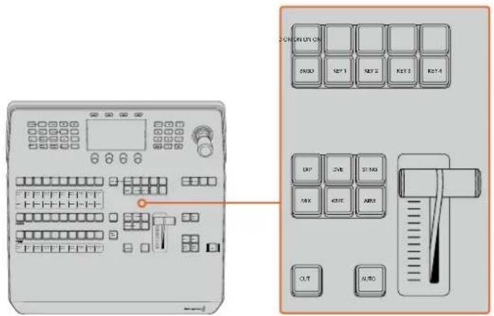
Transition Control Upstream Keyers
ON AIR
The ON AIR indicator buttons above each keyer are labelled ON and indicate which of the upstream keys are currently on air. These can also be used to immediately cut a key on or off air.
MACRO
The macro button is used to enable the macro feature which changes the source select row of buttons to macro buttons corresponding to macro slots.
TIP There are ten macro buttons in the source select row, so if you have macros recorded to slots greater than ten, you can access these by opening the macro settings in the LCD menu and changing the macro group using the control knob.
For more information on how to record and run macros using the advanced panel, refer to the 'Using Macros/Recording Macros using an ATEM 1 M/E Advanced Panel' section.
Downstream Keyers
DSK TIE
The DSK TIE button will enable the DSK on the preview output, along with the next transition effects and tie it to the main transition control so that the DSK can be taken to air with the next transition.
Because the tied downstream keyer is now tied to the main transition, the transition will happen at the rate specified in the auto rate setting in the LCD 'home' menu. When the DSK is tied, the signal routing to the clean feed 1 is unaffected.
DSK CUT
The DSK CUT button is used to cut the DSK on or off air and indicates whether the DSK is currently on or off air. The button is illuminated if the DSK is currently on air.
DSK AUTO
The DSK AUTO button will mix the DSK on or off air at the rate specified in the DSK rate LCD menu setting.
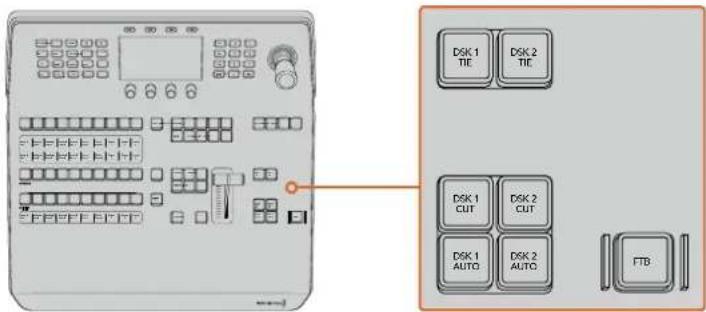
Downstream Keyers and Fade to Black
M/E Numbered Buttons
As some ATEM switchers have multiple M/Es you can select which one you want to control using the M/E buttons. When an M/E is selected, the LCD menu will change to show the settings that correspond to that M/E panel.
FTB
The FTB button will fade the program output to black at the rate specified in the FTB rate LCD menu setting. Once the program output has been faded to black, the FTB button will flash red until it is pressed again, fading the program output up from black at the same rate. A fade to black cannot be previewed.
You can also set your switcher to fade audio together with the fade to black by navigating to the FTB LCD menu and setting AFV to 'on'. This sets the switcher to fade the audio to silence at the rate set for the fade to black. If you want audio to remain on during and after the fade to black, set AFV to 'off'.
System Control Menu Buttons
The buttons on the top left side of your panel, combined with the LCD and its four soft buttons are called the system control. When you press a system control button, for example the 'home' button, the LCD will change accordingly to show the relevant controls and settings. Use the soft buttons and knobs above and below the LCD to make changes.
If there are small dot icons on the LCD menu, this means there is more than one page of settings and you can move through the pages by pressing the left and right arrow buttons.
For example, to change the border softness on a wipe transition
1 Press the 'wipe' button.
2 Press the right arrow button next to the LCD to move to the third page of settings.
3 Rotate the control knob under the 'softness' setting to change the softness of the wipe transition border.
If you want to change the direction of the wipe transition
1 Press the arrow buttons to navigate back to the first page of wipe transition settings, or press the 'wipe' button to return to the first page.
2 Press the 'reverse direction' soft button at the top of the LCD to change the direction.
3 Once you are satisfied with the setting, press the 'home' button to return to the home page.
TIP When changing the border softness, you can visually monitor your adjustments in real time. Simply press the PREV TRANS button and move the fader bar while watching the preview output on the multi view to visually monitor your settings. Remember to press PREV TRANS again to disable the transition preview when you're happy with the settings.
The system control buttons and LCD menu are used to access all the settings for your panel and you can even set general switcher settings directly from the panel. For example, if you need to change the switcher's video format, aspect ratio, or configure VISCA control on the remote port.
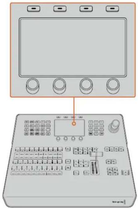
System Control
Joystick and Numeric Keypad
The number pad is used to enter numerical data. For example, the number pad can be used to enter a numerical value for transition duration. When entering data using the number pad, the soft buttons below each parameter are used to apply the entered data to that parameter.
The Joystick is a 3-axis joystick that is used to size and position keys, DVEs and other elements. You can also use the joystick to control VISCA PTZ remote cameras.
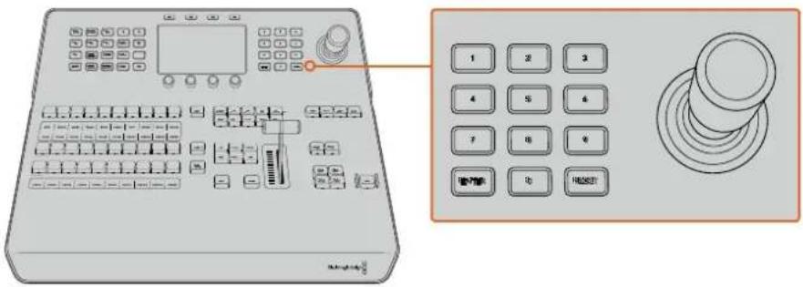
Joystick Control
Controlling Cameras using the Joystick
The joystick can also be used to control a remote camera head using the common VISCA protocol when connected to your switcher.
PTZ, or 'pan, tilt, zoom', control is an extremely powerful tool for controlling pan, tilt and zoom on remote cameras. You can easily control a bank of cameras one at a time by pressing the camera control button and then selecting each camera via the numbered buttons on the numeric keypad. Make your pan and tilt adjustments with the joystick.
You can also choose the tilt direction of your joystick by selecting 'inverted' or 'normal' in the 'VISCA control settings. Selecting 'inverted' will reverse the tilt action of your joystick.
Connecting a Remote Head
Your ATEM Advanced Panel communicates with remote heads via your ATEM switcher's RS-422 port labeled 'remote' or 'RS-422 serial out'. After connecting your ATEM Broadcast Panel to your ATEM switcher via Ethernet, connect your ATEM switcher to the RS-422 input on the remote camera head. RS-422 ports are typically DB-9/DE-9 serial ports, or RJ12 connectors that look similar to a standard landline phone connector.
You'll also need to make sure the remote behavior for your switcher's RS-422 port is set to 'PTZ in the 'settings' LCD menu.
When connecting more than one remote head, they will normally be daisy chained together via the RS-422 outputs/inputs between each head.
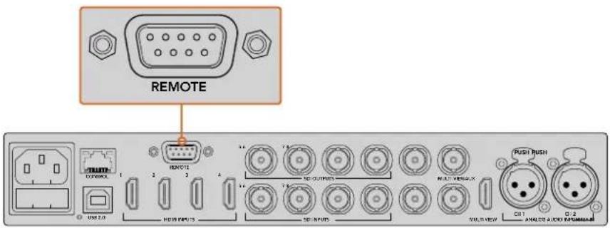
Connect a remote camera head to your ATEM switcher via the RS-422 port labelled 'remote' on the rear panel
PTZ Setup for Remote Heads
All PTZ setup options are set using the 'settings' LCD menu. Press the arrow buttons to move to the last page of switcher settings and set the remote port to VISCA. Set the baud rate to match the rate used by your PTZ camera. Refer to your camera's support documentation to confirm the appropriate baud rate.
Pressing the camera control button opens the camera settings, where you can select VISCA control and choose the camera you want to adjust. But first, you will need to make sure the connected cameras are detected.
To detect the connected devices:
1 Press the VISCA soft button to select VISCA control.
2 Press the 'detect' soft button.
The first camera connected to your switcher will appear on the LCD as 'camera 1'. If you have more than one camera connected, they can each be selected by turning the 'camera' soft control knob. Camera numbering is based on consecutive order from the first remote head connected, through to the last in the chain.
If the number of connected cameras that appear on the LCD menu don't match the physical number you have connected, check that all your camera heads are powered and their RS-422 ports are plugged in correctly. Once all your camera heads are visible on your ATEM advanced panel, select each camera using the soft control knob or numeric keypad and make some quick adjustments with the joystick to check they are all working properly.
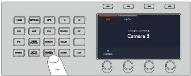
To use VISCA PTZ control, press the 'camera control' button and select VISCA by pressing the VISCA soft button.
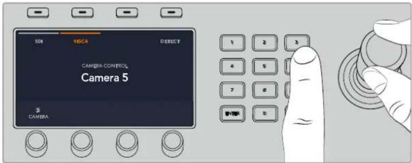
Select the camera you want to control and use the joystick to pan, tilt and zoom
TIP Camera control defaults to SDI for general camera control via SDI, so when using VISCA control, make sure you press the VISCA soft button to access VISCA PTZ cameras.
PTZ Control via SDI
You can also control PTZ camera heads via SDI. For example, by connecting the program return feed from your switcher to a Blackmagic Micro Studio Camera, then connecting the SDI output from the camera's expansion cable to your PTZ head, you can control the head via the SDI signal.
For more information on PTZ control using a Blackmagic Micro Studio Camera refer to the Blackmagic Studio Cameras manual. This manual can be downloaded from the Blackmagic Design support center at www.blackmagicdesign.com/support
Joystick PTZ Controls
Joystick PTZ controls are very intuitive. Turn the joystick knob clockwise or counter clockwise to zoom in and out. Push up and down to tilt the camera and push left and right to pan. The controls are sensitive to the degree of movement of the joystick, letting you ease in and out of your camera moves. The amount of sensitivity may vary between remote heads.
If you want to wire a custom built PTZ unit using a standard RS-422 port DB-9 connector, refer to the section labeled 'Using RS-422 for Custom Built PTZ Control'.
Button Mapping
ATEM software and hardware control panels support button mapping so you can assign your most important sources, especially cameras, to the most accessible buttons in the program and preview rows. Occasional sources can be assigned to less prominent buttons. Button mapping is set independently for each control panel so button mapping set on a software control panel will not affect the button mapping set on a hardware control panel.
ATEM Broadcast Panel Button Mapping and Button Brightness Level
To access the button mapping settings, press the 'settings' button to open the general switcher settings LCD menu, then press the 'button mapping' soft button.
Use the control knobs under each LCD setting to select the button you want to map and the input you want to change it to. You can also change the button color and label color that is displayed on the panel if you want to highlight specific sources. For example, you may want to highlight your playback sources a different color so you can instantly identify them on the panel. The button will illuminate on both the preview and program rows until the source is switched to the preview or program output, where it will change to green or red respectively.
Once you have changed the setting, the change is made instantly and you don't have to worry about saving. Press the 'home' button to return to the home menu.
If you want to change the brightness of the buttons, press the 'settings' button to open the general switcher settings LCD menu, then press the 'panel' soft button to reveal the panel settings.
Rotate the settings knob under each setting until you see the desired brightness level.
Once you have configured all the button settings, press the 'home' button to return to the home menu.
Performing Transitions using ATEM Hardware Panels
Performing transitions on ATEM hardware panels is part of the fun and excitement of switching a live broadcast! The buttons and knobs on the ATEM 1 M/E and 2 M/E Broadcast Panels follow the same M/E layout, plus the system control blocks share the same functions. This means controlling your switcher is intuitive when working with both broadcast panels because they operate your switcher in exactly the same way.
The ATEM 1 M/E Advanced Panel is similar to the broadcast panels with all the same M/E controls. However, the ATEM 1 M/E Advanced Panel uses a large LCD with soft control knobs and buttons which lets you adjust settings dynamically as you control your switcher. This is a fast and convenient way of working with your panel.
This section describes how to perform the various transition types on your switcher using an ATEM hardware panel.
Cut Transitions
The cut is the most basic transition that can be performed on the switcher. In a cut transition the program output is immediately changed from one source to another.

Program output for a cut transition.
A cut transition can be performed directly from the program bus, or using the CUT button in the transition control block.
Program Bus
When a cut transition is performed from the program bus, only the background will be changed and all upstream and downstream keys will maintain their current state.
To perform a cut transition from the program bus
On the program bus, select the video source that you want on the program output. The program output will immediately change to the new source.
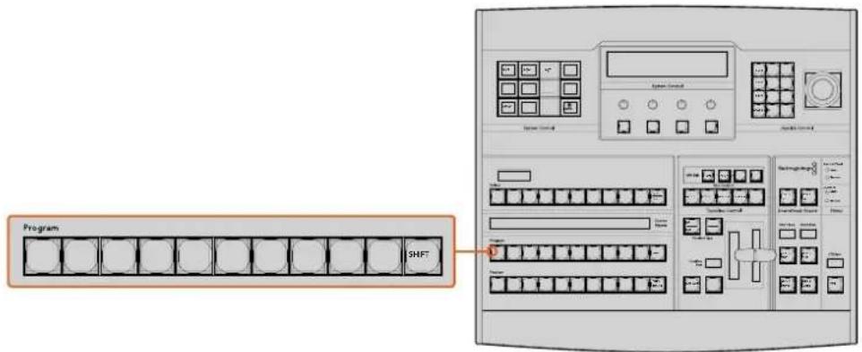
Press any of the source buttons on the program row to perform a cut transition from the program bus
CUT Button
When a cut transition is performed using the CUT button, any upstream keys that were selected in the next transition and any downstream keys that were tied to the transition control will also change state. For example, a downstream key tied to the transition control will cut ON if off air, or cut OFF if on air. Similarly, any upstream keys selected in the next transition will be cut on if they were off air, or cut off if they were on air.
To perform a cut transition using the CUT button
1 On the preview bus, select the video source that you want on the program output. The program output will remain unchanged.
2 In the transition control block, press the CUT button. The sources selected on the program and preview buses are exchanged to indicate that the video source that was on preview is now on program and vice versa.
TIP It's recommended to use the transition control block to perform transitions because it provides the opportunity to verify the video content on the preview output before sending it to the program output, for example to verify that a camera is in focus.
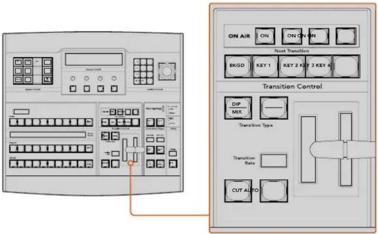
Press the button marked CUT in the transition control block to perform a cut transition
Auto Transitions
An auto transition allows you to automatically transition between program and preview sources at a predetermined rate. Any upstream keys that were selected in the next transition and any downstream keys that were tied to the transition control will also change state. Auto transitions are performed using the auto button in the transition control block. Mix, dip, wipe, DVE and stinger transitions can all be performed as an AUTO transition.
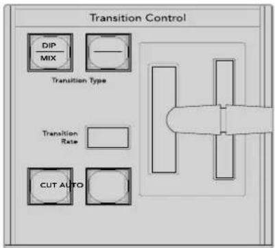
The auto transition button is part of the transition control block
To perform an auto transition
1 On the preview bus, select the video source that you want on the program output.
2 Select the transition type using the transition type buttons in the transition control block.
3 In the system control, set the transition rate and adjust any other parameter for the transition as needed.
TIP On the ATEM 1 M/E Advanced Panel, all transition settings are accessed via the LCD menu.
4 Press the AUTO button in the transition control block to initiate the transition.
5 During the transition, the red and green buttons on the program and preview buses both turn red to indicate that you are in the middle of a transition. The fader bar or transition slider indicator displays the position and progress of the transition and the transition rate display updates to indicate the number of frames remaining as the transition progresses.
6 At the end of the transition, sources selected on the program and preview buses are exchanged to indicate that the video source that was on preview is now on program and vice versa.
Each transition type has its own independent transition rate allowing you to perform faster transitions by selecting the transition type and pressing the AUTO button. The previously used transition rate is remembered for that transition type until it is changed.
A production switcher provides multiple methods of transitioning from one shot to another. Generally, you use a simple cut transition to move from one background source to another. Mix, dip, wipe and DVE transitions allow you to transition between two background sources by gradually phasing out one and phasing in another. Stinger and Graphic Wipe are special transitions which will be covered in a later section. Mix, dip, wipe and DVE transitions are performed as an auto transition or manual transition using the transition control block.
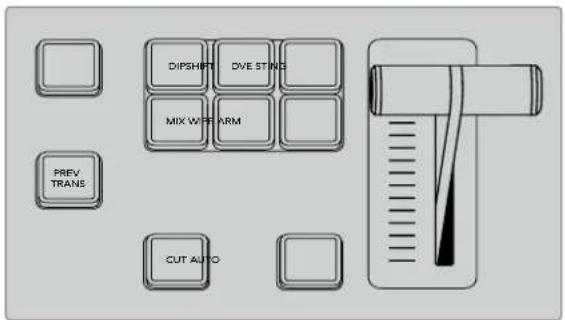
On the ATEM 1 M/E Advanced Panel the transition types, for example dip, mix and wipe, have their own independent selection button. ATEM broadcast panels share transition types for each button. The shared transition type is accessed by holding down the shift button and pressing the transition button.
Mix Transitions
A mix is a gradual transition from one source to another and is achieved by interpolating gradually between two sources, effectively overlapping the sources for the duration of the effect. The length of the transition or length of the overlap can be adjusted by changing the mix rate.

Program output for a mix transition.
To perform a mix transition on an ATEM broadcast panel
1 On the preview bus, select the video source that you want on the program output.
2 Press the DIP/MIX button to select the mix transition type. The system control automatically navigates to the transition menu. To manually navigate to the transition menu press HOME >TRANS.
3 In the control system, use the knob to adjust the mix rate. The transition rate display in the transition control block will update dynamically. You can also enter a rate duration using the number pad followed by the set rate button.
4 Perform the transition as an auto transition or manual transition from the transition control block.
Transition
Mix
1:00
Set Rate
Dip
1:00
Set Rate
FTB
1:00
Set Rate
Mix Transition Parameters
Rate
The mix transition rate in seconds : frames.
To perform a mix transition on the ATEM 1 M/E Advanced Panel
1 On the preview bus, select the video source that you want on the program output.
2 Press the MIX button to select the mix transition type. The LCD menu will automatically display the transition settings.
3 In the transition settings, use the corresponding LCD control knob to adjust the mix rate. You can also enter a rate duration using the number pad.
4 Perform the transition as an auto transition or manual transition from the transition control block.
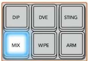
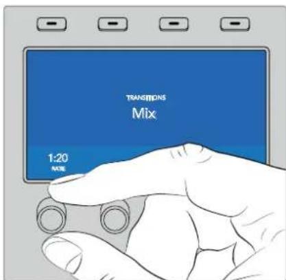
Press the 'mix' button and set the transition rate using the LCD menu
Dip Transitions
A DIP is similar to a mix in that it is a gradual transition that transitions from one source to another. However, a dip transition gradually mixes through a third source, the dip source.
For example, the dip transition can be used for a transition that calls for a white flash or a transition that quickly flashes the sponsor logo. The length of the dip transition and the dip source can both be customized.

Program output for a dlp transition.
To perform a dip transition on an ATEM broadcast panel
1 On the preview bus, select the video source that you want on the program output.
2 Press the SHIFT and DIP/MIX buttons to select the dip transition type. The DIP/MIX button illuminates green. The system control automatically navigates to the transition menu. To manually navigate to the transition menu press HOME >TRANS.
3 In the system control use the knob to adjust the dip rate. The transition rate display in the transition control block will update dynamically. You can also enter a rate duration using the number pad followed by the set rate button.
4 Use the select bus to select the dip source.
5 Perform the transition as an auto transition or manual transition from the transition control block.
To perform a dip transition on the ATEM 1 M/E Advanced Panel
1 On the preview bus, select the video source that you want on the program output.
2 Press the DIP button to select the dip transition type. The LCD menu will automatically display the transition settings.
3 In the transition settings, use the corresponding LCD control knob to adjust the dip rate. You can also enter a rate duration using the number pad. Select a dip source.
4 Perform the transition as an auto transition or manual transition from the transition control block.
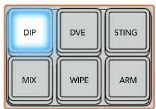
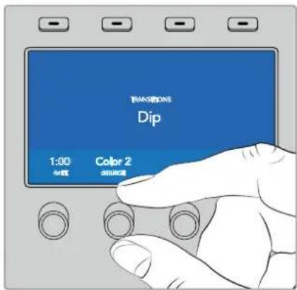
Press the 'dip' button in the transition control block, then set the dip source and transition rate using the LCD menu
Dip transition parameters
| Rate | The dip transition rate in seconds and frames. |
| Dip Source | The dip source is any video signal in the switcher that will be used as the intermediate picture for the dip transition, usually a color generator or media player. |
Wipe Transitions
A wipe is a transition from one source to another and is achieved by replacing the current source by another source with a pattern that forms a shape. For example an expanding circle or diamond.


Program output for a wipe transition.
To perform a wipe transition on an ATEM broadcast panel
1 On the preview bus, select the video source that you want on the program output.
2 Press the WIPE button to select the wipe transition type. The system control automatically navigates to the wipe patterns menu. To manually navigate to the wipe patterns menu press HOME > TRANS > WIPE PATTRN.
3 Use the system control menu buttons to select the wipe pattern.
4 Use the system control knobs and buttons to adjust border parameters and specify wipe direction. You can also enter a rate duration using the number pad followed by the set rate button.
5 Use the select bus to select the border source.
6 Perform the transition as an auto transition or manual transition from the transition control block.
To perform a wipe transition on the ATEM 1 M/E Advanced Panel
1 On the preview bus, select the video source that you want on the program output.
2 Press the WIPE button to select the wipe transition type. The LCD menu will automatically display the transition settings.
3 Press the desired wipe pattern button on the control panel.
4 In the transition settings, use the corresponding LCD control knobs to adjust the border parameters, the wipe rate and wipe direction. You can also enter a rate duration and specific setting values using the number pad.
5 Use the select bus to select the border source.
6 Perform the transition as an auto transition or manual transition from the transition control block.
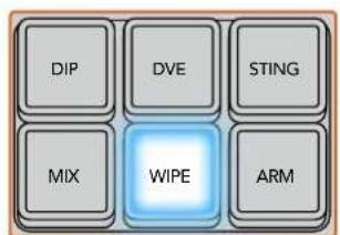
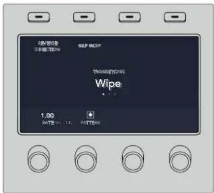
Press a source button in the source select row to select a source for the wipe border. Hold the shift button down to select a shifted source, such as a color generator or media player.
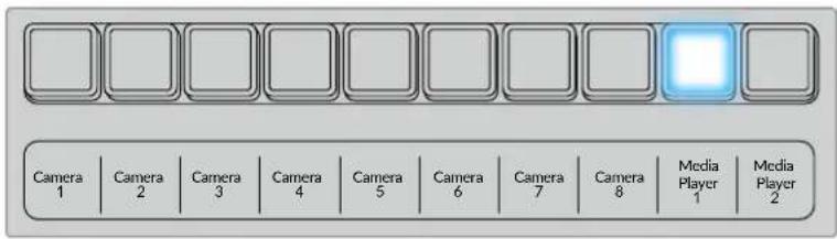
Press a source button in the source select row to select a source for the wipe border, such as a camera or media player.
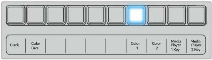
Hold the shift button down to select a shifted source, such as color bars or a color generator.
TIP The border source used in a wipe transition can be any source in the switcher. For example, a thick border with the media player as its source can be used for sponsorship or branding.
Wipe transition parameters
| Rate | The length of the wipe transition in seconds and frames. |
| Symmetry | Symmetry can be used to control the aspect ratio of the pattern. For example, adjusting the symmetry will allow you to change a circle into an ellipse. On the broadcast panel symmetry can be adjusted using the z axis of the joystick. |
| Position | If the wipe pattern has positioning then the joystick on the broadcast panel or the x position: and y position: boxes in the transition palette of the software control panel can be used to move the center of the pattern. Moving the joystick dynamically updates the x and y position display in the software control panel. |
| Normal | The normal direction for closed patterns such as circles, diamonds and boxes is to grow from the center of the screen and progress outward. |
| Reverse | Reverse changes the progression of closed patterns such as circles, diamonds and boxes so that the pattern closes in from the edges of the screen toward the center. |
| FlipFlop | When FlipFlop mode is toggled on, the transition changes between normal to reverse every time the transition is executed. |
| Border | Width of the border. |
| Soft | The edges of the wipe pattern can be adjusted between sharp and fuzzy by adjusting the softness parameter. |
DVE Transitions
Your ATEM switcher includes a powerful digital video effects processor for DVE transitions. A DVE transition displaces the image in various ways to transition from one picture to another. For example, a DVE transition can be used to squeeze the current picture off screen revealing a new video under it.
To perform a DVE transition on an ATEM broadcast panel
1 On the preview bus, select the video source that you want on the program output.
2 On the ATEM 2 M/E Broadcast Panel, press the DVE button which illuminates yellow. On the ATEM 1 M/E Broadcast Panel, press the SHIFT and WIPE/DVE buttons to select the DVE transition type. The WIPE/DVE button illuminates green to indicate the DVE transition type is selected. The system control automatically navigates to the DVE pattern menu. To manually navigate to the DVE pattern menu press HOME >TRANS >DVE PATTRN.
If the DVE is already being used in an upstream key, the message DVE unavailable will be displayed and the DVE transition type will not be available for selection until the key is taken off air and off next transition. Refer to sharing DVE resources later in this section for more information.
3 Use the system control menu buttons to select the DVE effects, graphic effects and to enable/disable the DVE Key.
4 Use the knobs and buttons in the system control to customize the DVE transition. You can also enter a DVE rate using the number pad followed by the set rate button.
5 If you are performing a graphic DVE/WIPE, use the select bus to select the logo fill source. Then press the DEST SHIFT or CUT/FILL button, depending upon your model of broadcast panel and use the select bus to select the logo cut source.
6 Perform the transition as an auto transition or manual transition from transition control.
To perform a DVE transition on the ATEM 1 M/E Advanced Panel
1 On the preview bus, select the video source that you want on the program output.
2 Press the DVE transition type button to select the DVE transition. The DVE settings will appear on the LCD menu.
NOTE If the DVE is already being used in an upstream key, the DVE transition type will not be available for selection until the key is taken off air and off next transition. Refer to 'sharing DVE resources' later in this section for more information.
3 In the DVE LCD menu, use the soft control knobs and buttons to configure the DVE parameters. For example, select the DVE pattern, movement, direction and adjust the DVE transition rate.
4 Perform the transition as an auto or manual transition using the auto button or fader bar.
DVE transition parameters
| DVE Rate The duration of the DVE transition in seconds and frames. Rotate the DVE rate knob to adjust the DVE transition rate. The new rate is immediately displayed in the transition rate window in the transition control block. | |
| Symmetry Symmetry can be used to control the aspect ratio of the pattern.For example, adjusting the symmetry will allow you to change a circle into an ellipse. On the broadcast panel symmetry can be adjusted using the z axis of the joystick. | |
| Position | If the wipe pattern has positioning then the joystick on the broadcast panel or the x position: and y position: boxes in the transition palette of the software control panel can be used to move the center of the pattern. Moving the joystick dynamically updates the x and y position display in the software control panel. |
| Normal The normal direction for closed patterns such as circles, diamonds and boxes is to grow from the center of the screen and progress outward. | |
DVE key parameters
| Enable key Enables/disables the DVE key. The DVE key is enabled when the button is illuminated. |
| PreMult Select the DVE key as a pre-multiplied key. |
| Clip The clip level adjusts the threshold at which the key cuts its hole. Decreasing the clip level reveals more of the background. If the background video is completely black then the clip value is too low. |
| Gain The gain adjustment electronically modifies the angle between on and off thereby softening the edges of the key. Adjust the gain value until the edge softness is desirable but the background video luminance (brightness) is not affected. |
| Inverse When the key is not pre-multiplied, inverts the key signal. |
Sharing DVE resources
ATEM features a DVE channel which can be used to perform DVE transitions or used in an upstream keyer. When you select a DVE transition, if the DVE is used elsewhere in the system, the DVE transition type will not be available and a DVE unavailable message will be displayed. In order to use the DVE transition you must free the DVE from where it is currently used. Verify that the upstream keys currently on program or preview are not DVE keys and do not have flying key enabled. To free DVE from the upstream keyer, change the key type to anything other than DVE or disable flying key. The DVE will be released and therefore available for use as a DVE transition.
The logo wipe transition is a popular transition that uses the DVE and moves a graphic across the screen over a background transition. For example, the logo wipe moves a graphic over a horizontal wipe, essentially replacing the wipe border. A logo mix spins the graphic across the screen over a mix transition. Logo transitions are perfect for wiping the station logo or spinning a football across the screen revealing a new background. Logo transitions use a special keyer built into the transition block, leaving all of the upstream and downstream keyers available for compositing the output. The following section explains how to build and perform logo transitions.

The above image sequence provides an example of the program output for a graphic wipe transition.
Performing a Graphic Transition
To perform a graphic transition on an ATEM broadcast panel
1 On the ATEM 2 M/E Broadcast Panel, press the DVE button which illuminates yellow. On the ATEM 1 M/E Broadcast Panel, press the SHIFT and WIPE/DVE buttons to select the DVE transition type. The WIPE/DVE button illuminates green to indicate the DVE transition type is selected.
NOTE If the DVE is already being used in an upstream key, the message DVE unavailable will be displayed and the DVE transition type will be unavailable for selection until the key is taken off air and off preview. Refer to sharing DVE resources in the next section for more information.
2 From the system control menu buttons, push next until you are on the DVE Graphics menu. You can also navigate to the DVE menu by selecting TRANS > DVE PATTRN from the home menu and repeatedly pushing 'Next' to get to the DVE Graphic page.
3 Select one of the two graphic mix buttons, depending on which way you want your graphic to spin across the screen.
4 Select the logo fill source and logo key source for the graphic from the select bus.
5 Set the rate and any other key parameters if required.
6 Perform the transition as an auto transition or manual transition from the transition control block.
To perform a graphic transition on the ATEM 1 M/E Advanced Panel
1 Press the DVE transition type button in the transition control block. The DVE settings menu will appear on the LCD.
If the DVE is already being used in an upstream key, the DVE transition type will not be available for selection until the key is taken off air and off next transition. Refer to 'sharing DVE resources' later in this section for more information.
2 Press the 'effect' soft button in the LCD menu to open the effect settings and set the effect to a graphic wipe by selecting the graphic wipe icon using the 'effect' soft control knob.
The default direction is left to right, but you can change the direction by selecting 'reverse direction'. You can also enable 'flip flop' which will let the effect move forwards and backwards with each performance of the transition, rather than repeating the same movement direction.
3 Press the right arrow in the system control buttons to adjust the key settings. Enable the key and select the fill and key source. If you need to make adjustments to the key, for example adjusting clip and gain settings, press the right arrow in the system control buttons to access the key parameters.
TIP Typically, for a graphic transition, the source would normally be a graphic loaded in a media player. By default, when you select a media player for the fill source, the key source will automatically select the media player key channel and set pre multiplied key to 'on'. This means a graphic with a key matte embedded in the alpha channel will automatically be selected by the switcher. You can disable pre multiplied key and change the key source if you want to use a separate media file on a different media player, or a different input source.
4 Press the auto button to perform the transition as an auto transition, or use the fader bar for a manual transition.
Description of graphic wipe parameters
| Rate | Rate specifies the length of the transition in seconds and frames.The rate can be adjusted using the rate knob or by entering a number on the number pad and pressing the set rate button. |
| Normal | The normal direction moves the graphic from left to right. |
| Reverse | Reverse changes the direction so that it moves the graphic from right to left. |
| FlipFlop | When FlipFlop mode is toggled on, the transition changes between normal and reverse every time the transition is executed. The ‘Normal’ or ‘Reverse’ light indicates the direction of the next transition. |
| Fill Source | The fill signal is the graphic used to move across the top of the transition. |
| Key Source | The key signal is a grayscale image that defines the region in the graphic that will be removed so that the fill signal can be correctly stacked on top of the wipe. |
Graphic wipe images
The graphic wipe feature requires a static graphic that is used as a moving border for a horizontal wipe. This graphic should be a vertical 'banner' type graphic that is no more than 25% of the total screen width.
natural_image
Pure black background with a faint white glow in the corner (no text or symbols)
natural_image
Completely black image with a faint white circular artifact in the top-left corner (no text or symbols)Graphic wipe screen width requirements
| 4320p | If the switcher is operating at 4320p then the graphic should be no wider than 1920 pixels. |
| 2160p | If the switcher is operating at 2160p then the graphic should be no wider than 960 pixels. |
| 1080i | If the switcher is operating at 1080i then the graphic should be no wider than 480 pixels. |
| 720p | If the switcher is operating at 720p than the graphic should be no wider than 320 pixels. |
| SD | If the switcher is operating in Standard Definition then the graphic should be no wider then 180 pixels. |
Manual Transitions
Manual transitions let you manually transition between program and preview sources using the fader bar in the transition control block. Mix, dip, wipe and DVE transitions can all be performed as a manual transition.
To perform a manual transition
1 On the preview bus, select the video source that you want on the program output.
2 Select the transition type using the transition type buttons in the transition control block.
3 Manually move the fader bar or transition slider from one end to the other to execute the transition. The next move on the fader bar or transition slider will begin a new transition.
4 During the transition the red and green buttons on the program and preview buses both turn red to indicate that you are in the middle of a transition. The LED indicator on the fader bar or transition slider also displays the position and progress of the transition.
TIP You will also see the ATEM software control panel mirror the move on the hardware panel.
5 At the end of the transition, sources selected on the program and preview buses are exchanged to indicate that the video source that was on preview is now on program and vice versa.
Using the ATEM 1 M/E Broadcast Panel
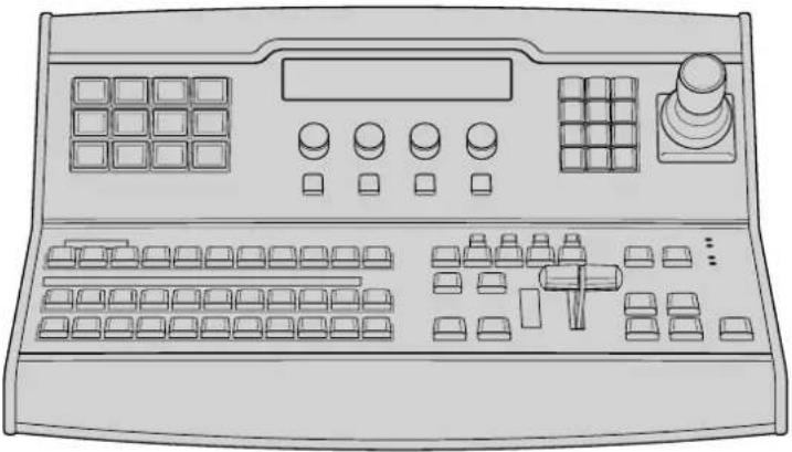
natural_image
Line drawing of a control panel with buttons, dials, and a keypad (no text or symbols)ATEM 1 M/E Broadcast Panel
Using the Control Panel
Mix Effects
The program bus, preview bus and source names display are used together to switch sources on the program and preview outputs.
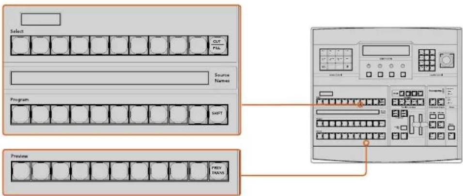
flowchart
graph TD
    A["Select"] --> B["OUT"]
    B --> C["FILL"]
    D["Program"] --> E["SHIFT"]
    F["Preview"] --> G["PREV"]
    G --> H["TRANS"]
ATEM Mix Effects
Source Names Display
The source names display uses a 4 character label to represent the switcher's external inputs or internal sources. Labels for the 8 external inputs can be edited on the settings window of the software control panel. Labels for the internal sources are fixed and don't need to be changed.
Pressing the SHIFT button will change the source names display to show extra sources, called shifted sources, allowing selection of up to 20 different sources.
When aux has been selected in the system control block, pressing the SHIFT and CUT/FILL buttons simultaneously will change the source names display to show protected sources, available for routing to auxiliary outputs. Protected sources are program, preview, clean feed 1 and clean feed 2.
Program Bus
The program bus is used to hot switch background sources to the program output. The source currently on air is indicated by a button that is illuminated red. A blinking red button indicates that the shifted source is on air. Pressing the SHIFT button will display the shifted source.
Preview Bus
The preview bus is used to select a source on the preview output. This source is sent to program when the next transition occurs. The selected source is indicated by a button that is illuminated green. A blinking green button indicates that the shifted source is on preview. Pressing the SHIFT button will display the shifted source.
SHIFT
The SHIFT button provides a global shift and is used to shift the program, preview and select busses along with the label. It also provides a shift for the transition type and joystick and other menu functions.
Double-pressing buttons in the preview and select busses, as well as the transition type buttons, is the same as shift-selecting them and can be a faster way to shift-select buttons. Double-pressing is not implemented for the program bus as it would cause the program output to momentarily show the wrong source.
Destination Display and Select Bus
The destination display works in conjunction with the source names display and select bus and is used to assign sources to auxiliary outputs and keyers.
The 8 character destination display and select bus together show you the routing of sources to keys and auxiliary outputs. The currently selected source is indicated by an illuminated button. A blinking button indicates a shifted source. A green illuminated button identifies a protected source. Protected sources are program, preview, clean feed 1 and clean feed 2.
CUT/FILL
When a key setup menu is selected and the CUT/FILL button is pressed, the destination display and select bus change to show the currently selected cut signal (also known as the Key signal) for that key. When selecting sources for auxiliary outputs, pressing the CUT/FILL button along with the SHIFT button displays program, preview, clean feed 1 and clean feed 2 as sources for selection on the select bus.
Transition Control and Upstream Keyers
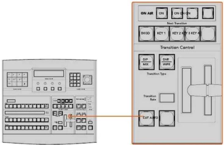
Transition Control and Upstream Keyers
CUT
The CUT button performs an immediate transition of the Program and Preview outputs, regardless of the selected transition type.
AUTO and Transition Rate
The AUTO button will perform the selected transition at the rate specified in the transition rate window. The transition rate for each transition type is set in the system control and is displayed in the transition rate window of the transition control block when the corresponding transition style button is selected.
The AUTO button illuminates red for the duration of the transition and the transition rate display updates to indicate the number of frames remaining as the transition progresses. If the software control panel is active, the virtual fader bar updates to provide visual feedback on the progress of the transition.
Fader Bar and Fader Bar Indicator
The fader bar is used as an alternative to the AUTO button and allows the operator to manually control the transition. The fader bar Indicator next to the fader bar provides visual feedback on the progress of the transition.
The AUTO button illuminates red for the duration of the transition and the transition rate display updates to indicate the number of frames remaining as the transition progresses. If the software control panel is active, the virtual fader bar updates to provide visual feedback on the progress of the transition.
Transition Type Buttons
The two transition type buttons allow the operator to select one of five types of transitions; mix, wipe, dip, DVE and stinger. Mix and wipe transition types are selected by pressing the appropriately labeled transition type button.
Dip and DVE transition types are selected by holding down the SHIFT button while pressing the desired transition type button, or by double-pressing the desired transition type button. The button will illuminate green indicating a shifted transition type.
The stinger transition type is selected by simultaneously pressing both transition type buttons. When stinger transitions are selected, both buttons will be illuminated green.
PREV TRANS
The PREV TRANS button enables the preview transition mode allowing the operator to verify a transition by performing it on the preview output using the fader bar. Once you press this button on, you can preview your transition as many times as you like allowing you to make changes and corrections as needed. You can even preview stinger transitions! Once adjusted, press the button off and you are ready to send your transition on air.
Next Transition
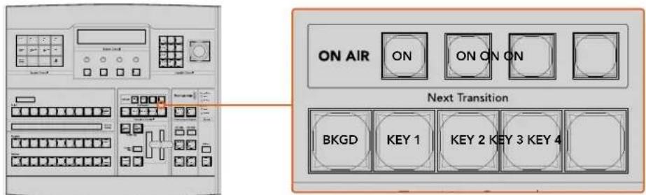
Transition Control and Upstream Keyers
The BKGD, KEY 1, KEY 2, KEY 3, KEY 4 buttons are used to select the elements which will transition on air or off air with the next transition. Any combination of background and keys can be selected by pressing multiple buttons simultaneously. Double-pressing the BKGD button selects all of the next transition upstream keyers that are currently on air and copies them to the Next Transition buttons.
Pressing any of the next transition buttons will clear selection of all others. When selecting the elements of the next transition, the switcher operator should look at the preview output because it provides an accurate representation of what the program output will look like after the transition is completed. When only the BKGD button is selected, a transition from the current source on the program bus to the source selected on the preview bus will occur.
ON AIR
The ON AIR indicator buttons indicate which of the upstream keys are currently on air and can also be used to immediately cut a key on or off air.
Downstream Keyers
DSK TIE
The DSK TIE button will enable the DSK on the preview output, along with the next transition effects and tie it to the main transition control so that the DSK can be taken to air with the next transition.
Because the tied downstream keyer is now tied to the main transition, the transition will happen at the rate specified in the transition rate display of the transition control block. When the DSK is tied, the signal routing to the clean feed 1 is unaffected.
DSK CUT
The DSK CUT button is used to cut the DSK on or off air and indicates whether the DSK is currently on or off air. The button is illuminated if the DSK is currently on air.
DSK AUTO
The DSK AUTO button will mix the DSK on or off air at the rate specified in the DSK rate window.
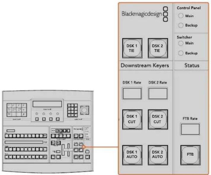
Downstream Keyers and Fade to Black
Fade to Black
FTB
The FTB button will fade the program output to black at the rate specified in the FTB rate window. Once the program output has been faded to black, the FTB button will flash red until it is pressed again, fading the program output up from black at the same rate. A fade to black cannot be previewed. You can also set your audio mixer to automatically fade the audio with your fade to black by selecting the master fader's AFV button.
System Status
The status lights provide feedback on the power supplies connected to the broadcast panel and the switcher. Not all ATEM switcher models have redundant power supplies so sometimes you will only see a single light illuminated for the power status of the switcher.
However if your switcher model has redundant power and you have two power supplies connected to the switcher and the control panel, then all the lights should be on. In this situation where you are using redundant power supplies, any light that turns off could indicate a power supply or cable is faulty and this should be checked.
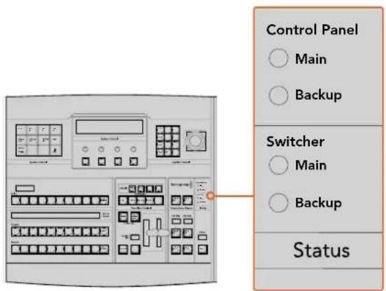
Power Status
System Control
The twelve menu buttons, the display window, the four knobs and the four soft buttons under the knobs together are called the system control. The 4 line display is used to identify the operation of the soft buttons and knobs.
The system control is context sensitive and allows you to adjust parameters for the current operation. For example if you enable KEY 1 in your next transition, the system control allows you to adjust the parameters of KEY 1. The system control is also used for configuring other parts of the switcher such as connecting and controlling HyperDeck disk recorders.
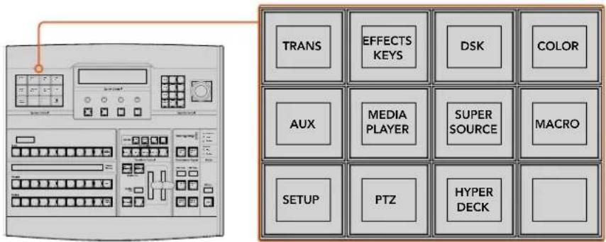
System Control
Menu Buttons
The matrix of menu buttons are organized into a multi level tree structure of pages that are very easy to navigate. To assist in rapid navigation all menu pages have a HOME button at the bottom right and most operations only require navigating down one level.
Joystick and Numeric Keypad
The Number Pad is used to enter numerical data. For example, when setting the transition rate of a transition, the number pad can be used to enter a numerical value for the transition duration. When entering data using the number pad, the soft buttons below each parameter are used to apply the entered data to that parameter.
The Joystick is a 3-axis joystick that is used to size and position keys, DVEs and other elements.
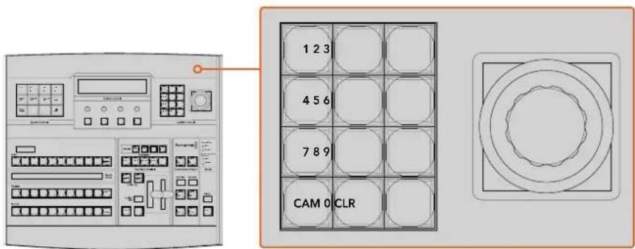
Joystick Control
Controlling Cameras using the Joystick
The joystick can also be used to control a remote camera head using the common VISCA protocol when connected to an ATEM 1 M/E or 2 M/E model switcher. This is an extremely powerful tool for controlling pan, tilt and zoom on remote cameras, also known as PTZ control. You can easily control a bank of cameras one at a time by selecting each camera using the system control soft buttons, then making your adjustments with the joystick.
You can also choose the tilt direction of your joystick by pressing the PTZ soft button on the panel, which will give you the options of 'normal' or 'inverted' to select from. Selecting 'inverted' will reverse the tilt action of your joystick.
Connecting a Remote Head
Your ATEM Broadcast Panel communicates with remote heads via your ATEM switcher's RS-422 port labeled 'remote' or 'RS-422 serial out'. After connecting your ATEM Broadcast Panel to your ATEM switcher via Ethernet, simply connect your ATEM switcher to the RS-422 input on the remote camera head. RS-422 ports are typically DB-9 serial ports, or RJ12 connectors that look similar to a standard landline phone connector.
You'll also need to make sure the remote behavior for your switcher's RS-422 port is set to 'PTZ' in the ATEM Software Control general settings.
When connecting more than one remote head, they will normally be daisy chained together via the RS-422 outputs/inputs between each head.
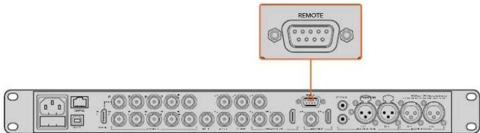
Connect a remote camera head to your ATEM 1 M/E or 2 M/E model switcher via the RS-422 port labeled 'remote' on the rear panel.
PTZ Setup for Remote Heads
All PTZ setup options are accessed via your ATEM Broadcast Panel's system control soft buttons. These soft buttons allow you to enter the PTZ soft menu so you can select cameras and enable the joystick for PTZ control, detect connected devices, plus select the 'baud' rate so you can control heads made by different manufacturers.
Once your remote heads are connected to your ATEM switcher, setting them up is easy.
To detect the connected devices:
1 Press the 'PTZ' soft button in the system control 'home' menu to access the PTZ setup options.
2 Press the 'Setup' soft button.
3 Press the 'detect' soft button.
A message will appear in the system control LED display describing the number of connected devices, which will also appear as camera numbers labeled on the system control soft buttons. Simply press the buttons to select each camera head. Camera numbering is based on consecutive order from the first remote head connected, through to the last in the chain.
For example, the first camera connected to your ATEM switcher will be labeled 'Cam 1', the second camera daisy chained to the first will be 'Cam 2', the third in the chain as 'Cam 3', etc.
If the number of connected devices that appear on the LED and soft buttons don't match the physical number you have connected, check that all your camera heads are powered and their RS-422 ports are plugged correctly. Once all your camera heads are visible on your ATEM Broadcast Panel, select each camera with the system control soft buttons and make some quick adjustments with the joystick to check they are all working properly.
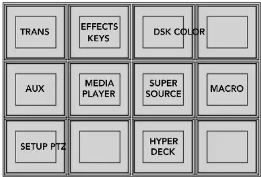
To access the PTZ buttons and enable PTZ joystick control, press the 'PTZ' button in the system control home menu.
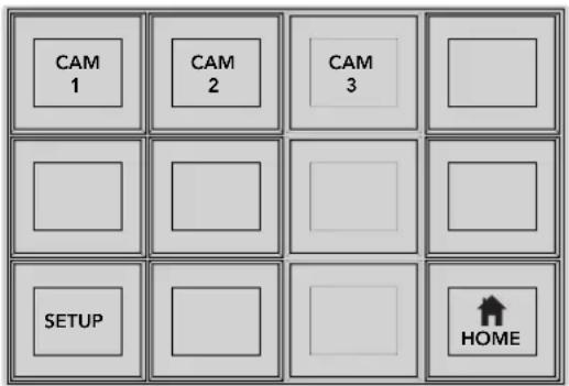
Select remote heads to control by pressing their respective camera number soft buttons.
Joystick PTZ Controls
Joystick PTZ controls are very intuitive. Simply turn the joystick knob clockwise or counter clockwise to zoom in and out. Push up and down to tilt the camera. Push left and right to pan. The controls are sensitive to the degree of movement of the joystick, letting you ease in and out of your camera moves. The amount of sensitivity may vary between remote heads.
If you want to wire a custom built PTZ unit using a standard RS-422 port DB-9 connector or RJ12 connector, see the 'Serial Port Pin Connections for Control Cables' section.
Controlling a HyperDeck
In ATEM 6.8 or newer, you can control up to 4 Blackmagic HyperDeck Studio disk recorders using your ATEM Broadcast Panel. This includes playback transport control and record features. All the configuration settings that can be set using ATEM Software Control can also be set using your hardware panel. For information on how to set up HyperDecks and control them using your ATEM Broadcast Panel, refer to the 'HyperDeck Control' section in this manual.
Button Mapping
ATEM software and hardware control panels support button mapping so you can assign your most important sources, especially cameras, to the most accessible buttons in the program and preview rows. Occasional sources can be assigned to less prominent buttons. Button mapping is set independently for each control panel so button mapping set on a software control panel will not affect the button mapping set on a hardware control panel.
Button Mapping
Selected Button Selected Input
Button 1 Input 1
Camera
ATEM Broadcast Panel button mapping
ATEM Broadcast Panel Button Mapping and Button Brightness Level
Button Mapping on ATEM Broadcast Panels is easy. On the ATEM Broadcast Panel, go to the System Control block and press PANEL SETUP followed by BUTTON MAP. Once in the button map menu, you will notice the System Control window shows a Button number and an Input number. Turn the knob under 'Selected Button' to select the desired button which you want to associate with an input. You can do the same thing by selecting the desired button in the Select row. The buttons in the Select row correspond to the buttons directly below them in the Preview and Program rows. Next, turn the knob under Selected Input to set an input for the selected button. Choose another button you wish to map and repeat until all the buttons are mapped with desired inputs.
If you want to change the brightness of the buttons, press the BUTTON LEVEL button and rotate the knob under 'Brightness' until the desired brightness level is seen.
Once you have configured all the button settings, press the SAVE button to save the new button map and brightness level, or REVERT to discard changes.
Using the ATEM 2 M/E Broadcast Panel
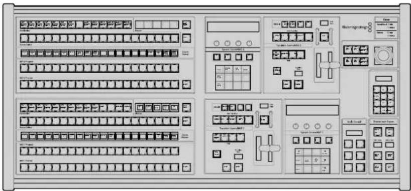
ATEM 2 M/E Broadcast Panel
Using the Control Panel
Mix Effects
The program bus, preview bus and source names display are used together to switch sources on the program and preview outputs.
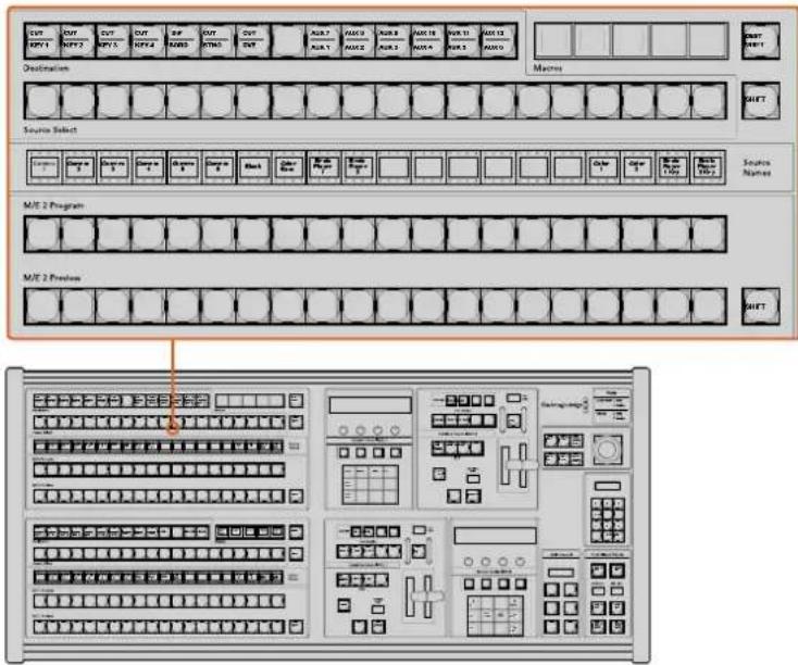
ATEM Mix Effects
Source Names Display
The source names display uses labels to represent the switcher's external inputs or internal sources. Labels for the external inputs can be edited on the settings tab of the software control panel. Labels for the internal sources are fixed and don't need to be changed.
Pressing the SHIFT button changes the source names display to show extra sources, called shifted sources, allowing selection of up to 40 different sources.
When aux has been selected in the system control block, or in the M/E 2 destination bus, pressing the two SHIFT buttons simultaneously will change the source names display to show protected sources, available for routing to auxiliary outputs. Protected sources are program, preview, clean feed 1 and clean feed 2.
Program Bus
The program bus is used to hot switch background sources to the program output. The source currently on air is indicated by a button that is illuminated red. A blinking red button indicates that the shifted source is on air. Pressing the SHIFT button will display the shifted source.
Preview Bus
The preview bus is used to select a source on the preview output. This source is sent to program when the next transition occurs. The selected source is indicated by a button that is illuminated green. A blinking green button indicates that the shifted source is on preview. Pressing the SHIFT button will display the shifted source.
SHIFT
The SHIFT button provides a global shift and is used to shift the program, preview and select busses along with source labels. It also provides a shift for the transition type and joystick and other menu functions.
Double-pressing buttons in the preview, select and destination busses, as well as the transition style buttons, is the same as shift-selecting them and can be a faster way to shift-select buttons. Double-pressing is not implemented for the program bus as it would cause the program output to momentarily show the wrong source.
Destination Bus and Select Bus
The destination bus gives you 1 key access to make changes to sources in your cuts and fills, borders and dip colors, stinger fills and cuts, DVE logos and cuts and down stream fills and cuts. To assign a source to one of these destinations, select any destination in the Destination bus and make your source selection in the Select bus below it.
The destination bus works in conjunction with the source names display and select bus to assign sources to auxiliary outputs and keyers.
The source names display and select bus together show you the routing of sources to keys and auxiliary outputs. The currently selected source is indicated by an illuminated button. A blinking button indicates a shifted source. A green illuminated button identifies a protected source. Protected sources are program, preview, clean feed 1 and clean feed 2.
DEST SHIFT button
To access the shifted destinations in the destination bus, hold down the DEST SHIFT button at the right side of the bus and make your selection.
CUT/KEY
When a key setup menu is selected and a CUT/KEY button is pressed, the select bus changes to show the currently selected cut signal (also known as the Key signal) for that key. When selecting sources for auxiliary outputs, pressing the two SHIFT buttons displays program, preview, clean feed 1 and clean feed 2 as sources for selection on the select bus.
Auxiliary Outputs
Aux crosspoint buttons are located in the M/E 2 destination bus. They can be used with an ATEM switcher which has aux outputs and which has been assigned to the M/E 2 block. Select the aux number in the destination bus and then select a source for it in the M/E 2 Source Select bus. See the later section "Using Auxiliary Outputs" for the many uses of auxiliary outputs.
The M/E 1 block doesn't have aux buttons. If an ATEM production switcher is assigned to the M/E 1 block, you can still access the aux outputs through the M/E 1 system control block. From any menu, select HOME and then AUX and you'll see the aux outputs are numbered. Select the aux output you wish to change and then select a new source for it in the Source Select bus.
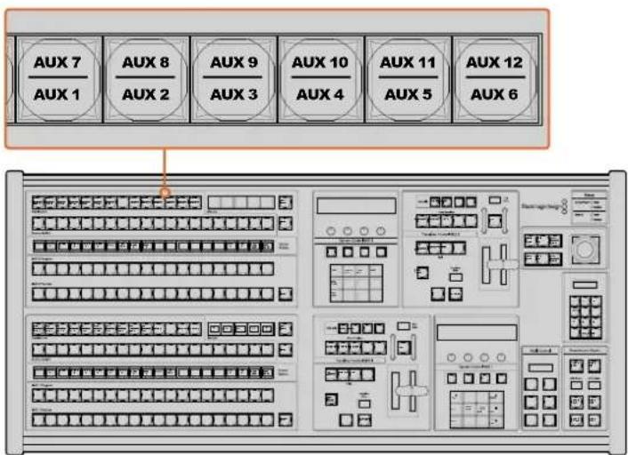
Auxiliary output buttons in the M/E 2 block
Transition Control and Upstream Keyers
The ATEM 2 M/E Broadcast Panel has independent transition controls and upstream keyers for the M/E 1 and M/E 2 blocks. They work exactly the same way in the M/E 1 and M/E 2 blocks. These independent controls are great for when you need to create different shows using each M/E as an isolated output.
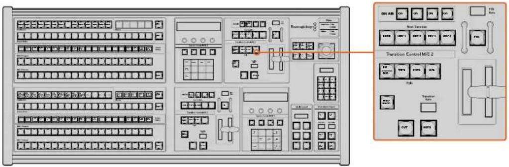
Transition Control and Upstream Keyers
CUT
The CUT button performs an immediate transition of the Program and Preview outputs, regardless of the selected transition type.
AUTO and Transition Rate
The AUTO button will perform the selected transition at the rate specified in the transition rate window.
The AUTO button illuminates red for the duration of the transition and the transition rate display updates to indicate the number of frames remaining as the transition progresses. If the software control panel is active, the virtual fader bar updates to provide visual feedback on the progress of the transition.
The transition rate for each transition style is set in the system control and is displayed in the transition rate window of the transition control block when the corresponding transition style button is selected.
Fader Bar and Fader Bar Indicator
The fader bar is used as an alternative to the AUTO button and allows the operator to manually control the transition. The fader bar Indicator next to the fader bar provides visual feedback on the progress of the transition.
The AUTO button illuminates red for the duration of the transition and the transition rate display updates to indicate the number of frames remaining as the transition progresses. If the software control panel is active, the virtual fader bar updates to provide visual feedback on the progress of the transition.
Transition Style Buttons
The transition style buttons allow the operator to select one of five styles of transitions; mix, wipe, dip, DVE and stinger. Mix, wipe, stinger and DVE transition styles are selected by pressing the appropriately labeled transition style button which will illuminate yellow.
The Dip transition style is selected by holding down the SHIFT button while pressing the DIP/MIX transition style button, or by double-pressing the DIP/MIX button. The button will illuminate green indicating a shifted transition style.
PREV TRANS
The PREV TRANS button enables the preview transition mode allowing the operator to verify a dip, mix, wipe or DVE transition by performing it on the preview output using the fader bar. Once you press this button on, you can preview your transition as many times as you like allowing you to make changes and corrections as needed. You can even preview stinger transitions! Once you are happy with the preview transition, press the button off and you are now ready to send your transition on air.
Next Transition
The BKGD, KEY 1, KEY 2, KEY 3, KEY 4 buttons are used to select the elements which will transition on air or off air with the next transition. Any combination of background and keys can be selected by pressing multiple buttons simultaneously. Double-pressing the BKGD button selects all of the next transition upstream keyers that are currently on air and copies them to the Next Transition buttons.
Pressing any of the next transition buttons will clear selection of all others. When selecting the elements of the next transition, the switcher operator should look at the preview output because it provides an accurate representation of what the program output will look like after the transition is completed. When only the BKGD button is selected, a transition from the current source on the program bus to the source selected on the preview bus will occur.
ON AIR
The ON AIR indicator buttons indicate which of the upstream keys are currently on air and can also be used to immediately cut a key on or off air.
Downstream Keyers
DSK TIE
The DSK TIE button will enable the DSK on the preview output, along with the next transition effects and tie it to the main transition control so that the DSK can be taken to air with the next transition.
Because the tied downstream keyer is now tied to the main transition, the transition will happen at the rate specified in the transition rate display of the transition control block. When the DSK is tied, the signal routing to the clean feed 1 is unaffected.
DSK CUT
The DSK CUT button is used to cut the DSK on or off air and indicates whether the DSK is currently on or off air. The button is illuminated if the DSK is currently on air.
DSK AUTO
The DSK AUTO button will mix the DSK on or off air at the rate specified in the DSK rate window.
Fade to Black
FTB
The FTB button will fade the program output to black at the rate specified in the FTB rate window. Once the program output has been faded to black, the FTB button will flash red until it is pressed again, fading the program output up from black at the same rate. A fade to black cannot be previewed. You can also set your audio mixer to automatically fade the audio with your fade to black by selecting the master fader's AFV button.
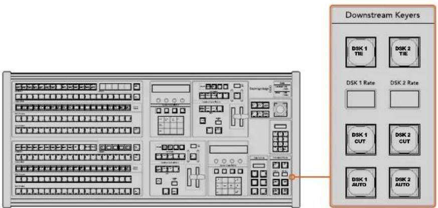
Downstream Keyers and Fade to Black
System Status
The status lights provide feedback on the internal or external power supplies running the broadcast panel and switchers. Not all ATEM switcher models have redundant power supplies so sometimes you will only see a single light illuminated for the power status of the switcher.
However if your switcher model has redundant power and you have two power supplies connected on the switcher and the control panel, then all the lights should be on. In this situation where you are using redundant power supplies, any light that turns off could indicate a power supply or cable is faulty and this should be checked.
When the 2 M/E panel is used to control two ATEM switchers, the switcher status lights indicate whether the two switchers are powered on. In this context, the "Main" switcher status light refers to the lower M/E 1 control block and "Backup" refers to the upper M/E 2 control block.
System Control
The twelve menu buttons, the display window, the four knobs and the four soft buttons under the knobs together are called the system control. The 4 line display is used to identify the operation of the soft buttons and knobs. The two system control blocks provide separate M/E 1 and M/E 2 controls.
The system control is context sensitive and allows you to adjust parameters for the current operation. For example if you enable KEY 1 in your next transition, the system control allows you to adjust the parameters of KEY 1. The system control is also used for configuring other parts of the switcher.
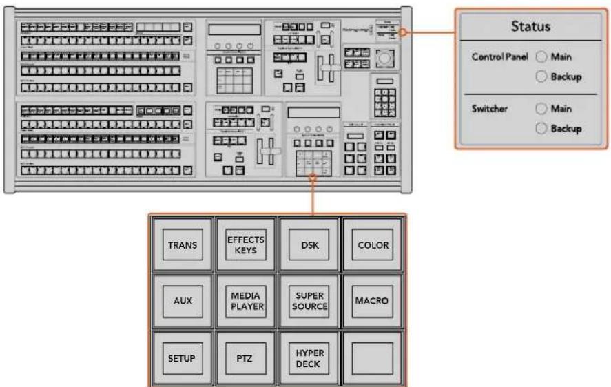
Power Status and System Control
Menu Buttons
The matrix of menu buttons are organized into a multi level tree structure of pages that are very easy to navigate. To assist in rapid navigation all menu pages have a HOME button at the bottom right and most operations only require navigating down one level.
Joystick and M/E Pattern and Key Buttons
You can use the joystick to quickly control keys and transitions by selecting the button corresponding to the M/E you are using and the parameter you wish to adjust.
M/E PATT
By selecting the M/E 1 PATT or M/E 2 PATT button, you can quickly get joystick control over size and the horizontal and vertical aspects of your selected transition.
M/E KEY
You can quickly move and resize upstream keys by selecting this button in the desired M/E when the KEY button is selected in the System Control Block of buttons.
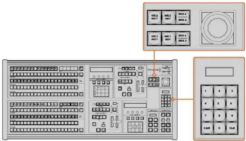
Joystick and M/E Pattern and Key Buttons
Joystick and Numeric Keypad
The Number Pad is used to enter numerical data. For example, when setting the transition rate, the number pad can be used to enter a numerical value. When entering data using the number pad, the soft buttons below each parameter are used to apply the entered data to that parameter.
The joystick and numeric keypad are shared between the M/E 1 and M/E 2 control blocks. They are context-sensitive which means any adjustments you make with them will solely be applied to the M/E control block in which you are currently working.
Controlling Cameras using the Joystick
The joystick can also be used to control a remote camera head using the common VISCA protocol when connected to an ATEM 1 M/E or 2 M/E model switcher. This is an extremely powerful tool for controlling pan, tilt and zoom on remote cameras, also known as PTZ control. You can easily control a bank of cameras one at a time by selecting each camera using the system control soft buttons, then making your adjustments with the joystick.
Connecting a Remote Head
Your ATEM Broadcast Panel communicates with remote heads via your ATEM switcher's RS-422 port labeled 'remote' or 'RS-422 serial out'. After connecting your ATEM Broadcast Panel to your ATEM switcher via Ethernet, simply connect your ATEM switcher to the RS-422 input on the remote camera head. RS-422 ports are typically DB-9 serial ports, or RJ12 connectors that look similar to a standard landline phone connector.
When connecting more than one remote head, they will normally be daisy chained together via the RS-422 outputs/inputs between each head.
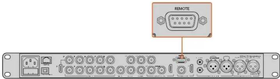
Connect a remote camera head to your ATEM 1 M/E or 2 M/E model switcher via the RS-422 port labeled 'remote' on the rear panel.
PTZ Setup for Remote Heads
All PTZ setup options are accessed via your ATEM Broadcast Panel's system control soft buttons. These soft buttons allow you to enter the PTZ soft menu so you can select cameras and enable the joystick for PTZ control, detect connected devices, plus select the 'baud' rate so you can control heads made by different manufacturers.
Once your remote heads are connected to your ATEM switcher, setting them up is easy.
To detect the connected devices:
1 Press the 'PTZ' soft button in the system control 'home' menu to access the PTZ setup options.
2 Press the 'Setup' soft button.
3 Press the 'detect' soft button.
A message will appear in the system control LED display describing the number of connected devices, which will also appear as camera numbers labeled on the system control soft buttons. Simply press the buttons to select each camera head. Camera numbering is based on consecutive order from the first remote head connected, through to the last in the chain. For example, the first camera connected to your ATEM switcher will be labeled 'Cam 1', the second camera daisy chained to the first will be 'Cam 2', the third in the chain as 'Cam 3', etc.
If the number of connected devices that appear on the LED and soft buttons don't match the physical number you have connected, check that all your camera heads are powered and their RS-422 ports are plugged correctly. Once all your camera heads are visible on your ATEM Broadcast Panel, select each camera with the system control soft buttons and make some quick adjustments with the joystick to check they are all working properly.
Joystick PTZ Controls
Joystick PTZ controls are very intuitive. Simply turn the joystick knob clockwise or counter clockwise to zoom in and out. Push up and down to tilt the camera. Push left and right to pan. The controls are sensitive to the degree of movement of the joystick, letting you ease in and out of your camera moves. The amount of sensitivity may vary between remote heads.
If you want to wire a custom built PTZ unit using a standard RS-422 port DB-9 connector or RJ12 connector, see the 'Serial Port Pin Connections for Control Cables' section.
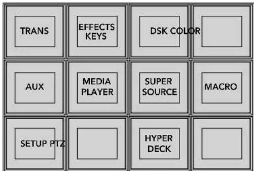
To access the PTZ buttons and enable PTZ joystick control, press the 'PTZ' button in the system control home menu.
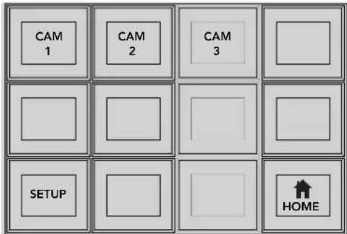
Select remote heads to control by pressing their respective camera number soft buttons.
Controlling a HyperDeck
In ATEM 6.8 or newer, you can control up to 4 Blackmagic HyperDeck Studio disk recorders using your ATEM Broadcast Panel. This includes playback transport control and record features. All the configuration settings that can be set using ATEM Software Control can also be set using your hardware panel. For information on how to set up HyperDecks and control them using your ATEM Broadcast Panel, refer to the 'HyperDeck Control' section in this manual.
Button Mapping
ATEM software and hardware control panels support button mapping so you can assign your most important sources, especially cameras, to the most accessible buttons in the program and preview rows. Occasional sources can be assigned to less prominent buttons. Button mapping is set independently for each control panel so button mapping set on a software control panel will not affect the button mapping set on a hardware control panel.
Button Mapping
Selected Button Selected Input
Button 1 Input 1
Camera 1
ATEM Broadcast Panel button mapping
ATEM Broadcast Panel Button Mapping and Button Brightness Level
Button Mapping on ATEM Broadcast Panels is easy. On the ATEM Broadcast Panel, go to the System Control block and press PANEL SETUP followed by BUTTON MAP. Once in the button map menu, you will notice the System Control window shows a Button number and an Input number. Turn the knob under Selected Button to select the desired button which you want to associate with an input. You can do the same thing by selecting the desired button in the Select row. The buttons in the Select row correspond to the buttons directly below them in the Preview and Program rows. Next, turn the knob under Selected Input to set an input for the selected button. Choose another button you wish to map and repeat until all the buttons are mapped with desired inputs.
If you want to change the brightness of the buttons, press the BUTTON LEVEL button and rotate the knob under Brightness until the desired brightness level is seen.
Once you have configured all the button settings, press the SAVE button to save the new button map and brightness level, or REVERT to discard changes.
Controlling Two ATEM Switchers
The ATEM 2 M/E Broadcast Panel can be used to control any dual combination of the following ATEM switchers simultaneously: ATEM 1 M/E Production Switcher, ATEM Television Studio and ATEM Production Studio 4K models.
The M/E 1 block is the main control block and has a few more settings that can be useful for an ATEM 1 M/E Production Switcher, or ATEM Production Studio 4K models. To use these additional settings assign an ATEM Production Studio 4K or 1 M/E Production Switcher to the lower block of your ATEM 2 M/E Broadcast Panel. If both of your switchers are of the same model, it doesn't matter which one you assign to the M/E 1 and M/E 2 blocks.
However, if you need quick access to switch auxiliary outputs using the panel buttons, we suggest assigning System Control M/E 2 to the ATEM Production Studio 4K models or M/E Production Switchers. This will let you take advantage of the Aux buttons which only appear in the M/E 2 block.
If using the default IP settings when using two switchers on the same network, their IP address will initially be the same, i.e. 192.168.10.240. You should change one of them to 192.168.10.241, or use an IP address somewhere in the 192.168.10.24_ range to keep all your switchers neatly together. Please follow the steps detailed in the earlier section "Changing the Switcher Network Settings".
When connecting the ATEM 2 M/E Broadcast Panel to two switchers, you need to change the switcher IP on one of the system control blocks to connect to the switcher whose IP address you have just changed. By default the System Control M/E 1 block connects to 192.168.10.240 and so you will only need to change the System Control M/E 2 block if you are using default settings.
To set network location of multiple switchers on the ATEM 2 M/E Broadcast Panel, simply follow these steps for each System Control M/E block:
1 When there is no communication with the switcher, the NETWRK SETUP menu will appear on the broadcast panel system control. Select the NETWRK SETUP menu button. If there is communication with a switcher, hold down SHIFT and DEST SHIFT and select the NETWRK SETUP button.
2 Select the SWITCHR IP menu button and use the knobs or the numeric keypad to edit each field as required.
3 When a field is changed, SAVE and REVERT menu buttons become available. Select SAVE to save the changed IP address. The system control display will show it is connecting to the switcher and will display the model of switcher once it has successfully connected.
This does not change the IP address of the switcher itself. It just changes where the control panel is looking to find the switcher. If the control panel cannot find the switcher, then you might need to check the switcher processor to see if it's been set correctly. To change the IP address of the switcher, connect the switcher via USB to a computer and run Blackmagic ATEM Setup software as described previously in this manual.
Operating your ATEM Switcher
Internal Video Sources
In addition to the SDI and HDMI inputs, the switcher also has 8 internal sources that can be used in a production. The internal source names are represented on the software control panel using a long name. On the broadcast panel, a short name is used to represent the internal sources and the labels represent what the sources are, so they are easy to understand.
Black
Internally generated black is available as a source and can be used as a black matte in the production.
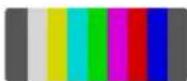
Color Bars
Internally generated color bars are available as a source. Color bars can be useful for verifying signals going out of the switcher and can also be useful when setting up a chroma key with a vectorscope monitor.

Color Generators
ATEM switchers have two color sources that can be customized to generate any color matte for use in the production. Color sources can be used to add color borders for wipe transitions or as dip through colors for a dip transition such as dip through white.
To adjust a color source on the software control panel, simply go to the color palette and click the color chip and the color picker will appear and you can select colors. On the broadcast panel, select color on the system control and adjust hue, saturation and luminance.
It's important to know that the deepest colors are set at 50% luminance.
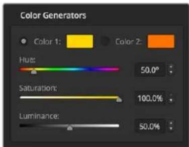
ATEM switchers have two color sources that can be customized to generate any color matte for use in the production.
Media Players
Most ATEM switchers have 2 media player sources, except for ATEM 4 M/E Broadcast Studio 4K which has 4 media player sources. ATEM Constellation 8K has 4 media players in HD and Ultra HD and one media player in 8K. Each media player source has a fill and key (cut) output. Media player fill sources are called media player 1, 2, 3 or 4. Media player key sources are called media player 1 key, media player 2 key, etc.
If you are using an ATEM switcher with more than 2 media players, media players 3 and 4 can be accessed in ATEM Software Control by holding down the shift button on your computer keyboard.
To select media players 3 and 4 on the front panel of ATEM 4 M/E Broadcast Studio 4K, double press 'mp1' to select media player 3, or double press 'mp2' for media player 4. Apply the same double press method using the 'mp 1 key' and 'mp 2 key' buttons to select media player 3 key and media player 4 key. The buttons will flash to indicate you have the additional media players selected.
The media player sources are used to play stills and clips from the media pool. The fill sources show the color channels of the selected clip or still while the key sources show the black and white alpha channel of the selected clip or still. Media players can be used in many parts of the production.
Controlling media players on the software control panel
1 From the switcher window, select the media player palette.
2 Use the select media drop down list to select a clip or still from the media pool.
3 If you have selected a motion clip, the begin, step back, play/pause, step forward and loop transport controls will be enabled for controlling the clip. If you want to loop a clip, then select the loop button and press play. The media player will keep looping until selected to stop.
Controlling media players on the broadcast panel
1 From the system control menu buttons, navigate to the Media Player menu by selecting MEDIA PLAYER from the HOME menu.
2 Select the media player you want to control.
3 Select 'Stills' or 'Clips' mode.
4 In stills mode, use the knob or the STEP BCK and STEP FWD buttons to select a still from the media pool. In this panel, you see the still number and filename to show what still you have selected.
5 In clip mode, use the knob to select clip 1 or clip 2. If a clip is loaded in the media pool, the transport controls will be enabled and can be used to play/pause, jump to begin and loop the clip. You cannot step forward and step back on a clip from the broadcast panel.
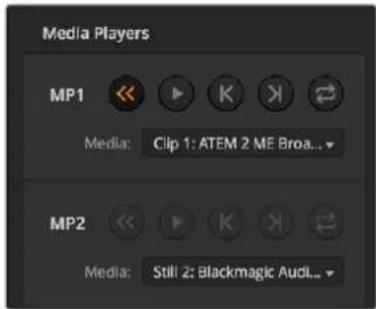
Media players showing a clip loaded into each.
Performing Transitions
One of the primary functions of a broadcast switcher is performing transitions from one video source to another. The combinations of transition effects and styles provide endless creative options that can enhance your production in just the right way for the right moment.
You can perform transitions using ATEM Software Control or an ATEM hardware control panel such as an ATEM broadcast panel, or an ATEM 1 M/E Advanced Panel. This section shows you how to perform the various transitions available on your switcher.
Cut Transitions
The cut is the most basic transition that can be performed on the switcher. In a cut transition the program output is immediately changed from one source to another.

Program output for a cut transition.
A cut transition can be performed directly from the program bus, or using the CUT button in the transition control block.
Program Bus
When a cut transition is performed from the program bus, only the background will be changed and all upstream and downstream keys will maintain their current state.
To perform a cut transition from the program bus on the software control panel
1 On the program bus, select the video source that you want on the program output next. The program output will immediately change to the new source.
To perform a cut transition on the software control panel using a keyboard
1 Enable
2 Press the number key on the keyboard corresponding to the video source that you want on the program output. The program output will immediately change to the new source.
To perform a cut transition from the program bus on an ATEM hardware panel
On the program bus, select the video source that you want on the program output. The program output will immediately change to the new source.
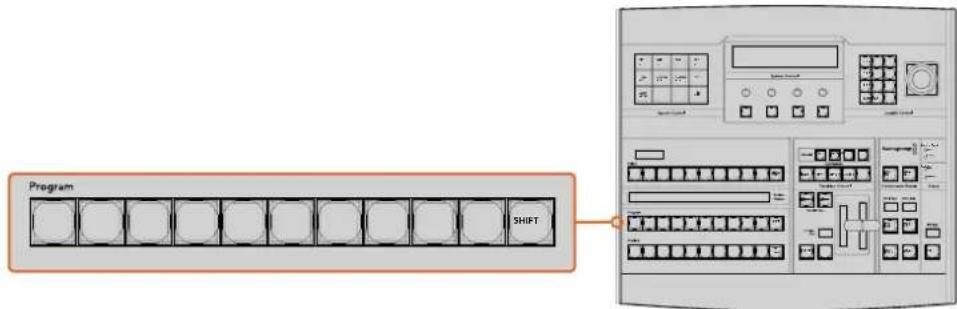
Press any of the source buttons on the program row to perform a cut transition from the program bus
CUT Button
When a cut transition is performed using the CUT button, any upstream keys that were selected in the next transition and any downstream keys that were tied to the transition control will also change state. For example, a downstream key tied to the transition control will cut ON if off air, or cut OFF if on air. Similarly, any upstream keys selected in the next transition will be cut on if they were off air, or cut off if they were on air.
To perform a cut transition using the CUT button on the software control panel
1 On the preview bus, select the video source that you want on the program output. The program output will remain unchanged.
2 In the transition control block, press the CUT button. The sources selected on the program and preview buses are exchanged to indicate that the video source that was on preview is now on program and vice versa.
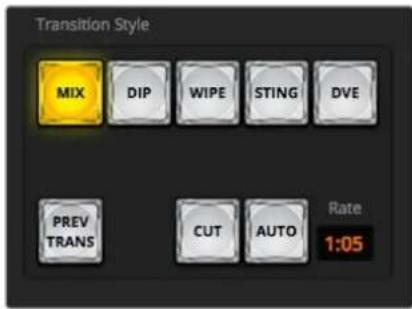
The Cut transition button is part of the Transitions Style group
To perform a cut transition on the software control panel using a keyboard
1 Ensure that
2 Press the number key on the keyboard corresponding to the video source that you want on the program output. The source will be selected on preview and the program output will remain unchanged.
3 Press
To perform a cut transition using the CUT button on an ATEM hardware panel
1 On the preview bus, select the video source that you want on the program output. The program output will remain unchanged.
2 In the transition control block, press the CUT button. The sources selected on the program and preview buses are exchanged to indicate that the video source that was on preview is now on program and vice versa.
It's recommended to use the transition control block to perform transitions because it provides the opportunity to verify the video content on the preview output before sending it to the program output, for example to verify that a camera is in focus.
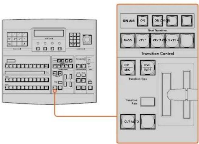
Auto Transitions
An auto transition allows you to automatically transition between program and preview sources at a predetermined rate. Any upstream keys that were selected in the next transition and any downstream keys that were tied to the transition control will also change state. Auto transitions are performed using the auto button in the transition control block. Mix, dip, wipe, DVE and stinger transitions can all be performed as an AUTO transition.
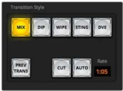
The Auto transition button is part of the Transitions Style group
To perform an auto transition on the software control panel
1 On the preview bus, select the video source that you want on the program output.
2 Select the transition type using the TRANSITION STYLE buttons in the transition control block.
3 In the transition palette, select the settings tab for the same transition type as the transition control block.
4 Set the transition rate and adjust any other parameter for the transition as needed.
5 Press the AUTO button in the transition control block to initiate the transition.
6 During the transition, the red and green buttons on the program and preview buses both turn red to indicate that you are in the middle of a transition. The virtual fader bar automatically follows the progress of the transition and the rate display updates to indicate the number of frames remaining as the transition progresses.
7 At the end of the transition, sources selected on the program and preview buses are exchanged to indicate that the video source that was on preview is now on program and vice versa.
To perform an auto transition on the software control panel using a keyboard
1 Ensure that
2 Press the number key on the keyboard corresponding to the video source that you want on the program output. The source will be selected on preview and the program output will remain unchanged.
3 Select the transition type using the transition style buttons in the transition control block.
4 In the transition palette, select the settings tab for the same transition type as the transition control block.
5 Set the transition rate and adjust any other parameter for the transition as needed.
6 Press the
7 During the transition, the red and green buttons on the program and preview buses both turn red to indicate that you are in the middle of a transition. The virtual fader bar automatically follows the progress of the transition and the rate display updates to indicate the number of frames remaining as the transition progresses.
8 At the end of the transition, sources selected on the program and preview buses are exchanged to indicate that the video source that was on preview is now on program and vice versa.
To perform an auto transition on an ATEM hardware panel
1 On the preview bus, select the video source that you want on the program output.
2 Select the transition type using the transition type buttons in the transition control block.
3 In the system control, set the transition rate and adjust any other parameter for the transition as needed.
4 Press the AUTO button in the transition control block to initiate the transition.
5 During the transition, the red and green buttons on the program and preview buses both turn red to indicate that you are in the middle of a transition. The fader bar indicator displays the position and progress of the transition and the transition rate display updates to indicate the number of frames remaining as the transition progresses.
6 At the end of the transition, sources selected on the program and preview buses are exchanged to indicate that the video source that was on preview is now on program and vice versa.
Each transition type has its own independent transition rate allowing the operator to perform faster transitions by simply selecting the transition type and pressing the AUTO button. The previously used transition rate is remembered for that transition type until it is changed.
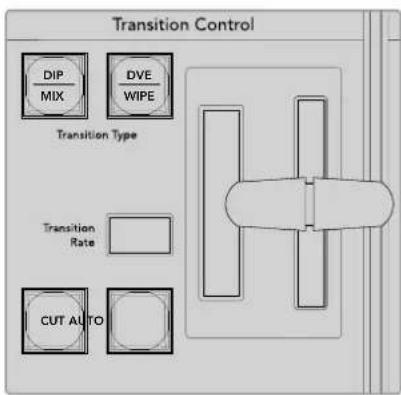
The ATEM 1 M/E Broadcast Panel shares transition types for each button and the second transition type is accessed by holding down the shift button and pressing the transition button
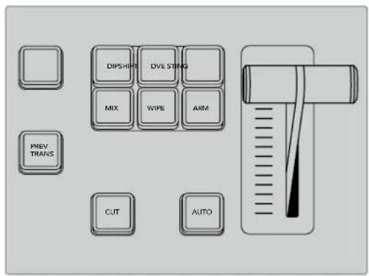
On the ATEM 1 M/E Advanced Panel the transition types, for example dip, mix and wipe, have their own independent selection button
A production switcher provides multiple methods of transitioning from one shot to another. Generally, you use a simple cut transition to move from one background source to another. Mix, dip, wipe and DVE transitions allow you to transition between two background sources by gradually phasing out one and phasing in another. Stinger and Graphic Wipe are special transitions which will be covered in a later section. Mix, dip, wipe and DVE transitions are performed as an auto transition or manual transition using the transition control block.
Mix Transitions
A mix is a gradual transition from one source to another and is achieved by interpolating gradually between two sources, effectively overlapping the sources for the duration of the effect. The length of the transition or length of the overlap can be adjusted by changing the mix rate.

Program output for a mix transition.
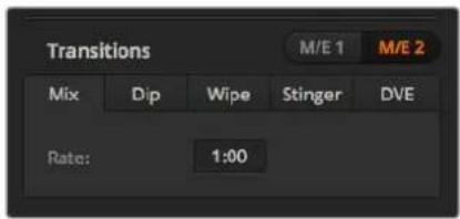
Mix Transition rate setting
To perform a mix transition on the software control panel
1 On the preview bus, select the video source that you want on the program output.
2 Select the mix transition style in the transition control block.
3 Expand the transition palette and select mix from the transition types bar.
4 Adjust the mix rate by entering a number in the rate window. The rate display in the transition control block will update.
5 Perform the transition as an auto transition or manual transition from the transition control block.
To perform a mix transition on an ATEM hardware panel
1 On the preview bus, select the video source that you want on the program output.
2 Press the DIP/MIX or MIX button to select the mix transition type. The system control automatically navigates to the transition menu. To manually navigate to the transition menu on ATEM broadcast panels, press HOME >TRANS.
3 In the system control panel, use the knob to adjust the mix rate. The transition rate display in the broadcast panel's transition control block will update dynamically. You can also enter a rate duration using the number pad.
4 Perform the transition as an auto transition or manual transition from the transition control block.
| Transition | ||
| Mix | Dip | FTB |
| 1:00 | 1:00 | 1:00 |
| Set Rate | Set Rate | Set Rate |
After setting a transition on an ATEM broadcast panel, confirm the change by pressing the 'set rate' soft button
Mix Transition Parameters
Rate
The mix transition rate in seconds : frames.
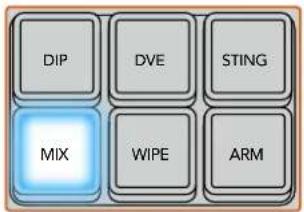
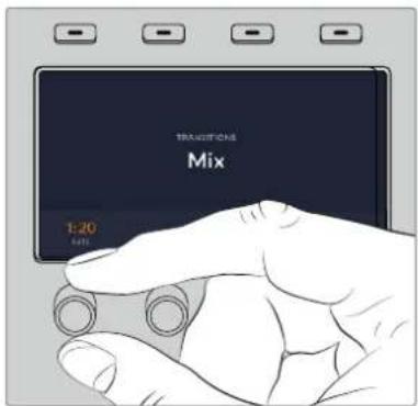
On ATEM 1 M/E Advanced Panel, press the 'mix' button and set the transition rate using the LCD menu
Dip Transitions
A DIP is similar to a mix in that it is a gradual transition that transitions from one source to another. However, a dip transition gradually mixes through a third source, the dip source. For example, the dip transition can be used for a transition that calls for a white flash or a transition that quickly flashes the sponsor logo. The length of the dip transition and the dip source can both be customized.

Program output for a dip transition.
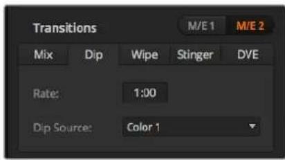
Dip Transition Settings
To perform a dip transition on the software control panel
1 On the preview bus, select the video source that you want on the program output.
2 Select the DIP transition style in the transition control block.
3 Expand the transition palette and select dip from the transition types bar.
4 Adjust the dip rate by entering a number in the rate window. The rate display in the transition control block will update.
5 Select the dip source.
6 Perform the transition as an auto transition or manual transition from the transition control block.
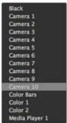
Dip Source Menu
To perform a dip transition on an ATEM hardware panel
1 On the preview bus, select the video source that you want on the program output.
2 Press the DIP button to select the dip transition type. The LCD menu will automatically display the transition settings.
NOTE On an ATEM broadcast panel, press the SHIFT and DIP/MIX buttons to select the dip transition type. The DIP/MIX button illuminates green. The system control automatically navigates to the transition menu. To manually navigate to the transition menu press HOME >TRANS.
3 In the system control use the control knob to adjust the dip rate. You can also enter a rate duration using the number pad.
4 Use the corresponding control knob to select the dip source. You can also use the select bus to select a dip source.
5 Perform the transition as an auto transition or manual transition from the transition control block.
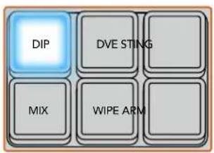
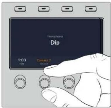
On ATEM 1 M/E Advanced Panel, press the 'dip' button in the transition control block, then set the dip source and transition rate using the LCD menu
Dip transition parameters
| Rate | The dip transition rate in seconds and frames. |
| Dip Source | The dip source is any video signal in the switcher that will be used as the intermediate picture for the dip transition, usually a color generator or media player. |
Wipe Transitions
A wipe is a transition from one source to another and is achieved by replacing the current source by another source with a pattern that forms a shape. For example an expanding circle or diamond.



Program output for a wipe transition.
To perform a wipe transition on the software control panel
1 On the preview bus, select the video source that you want on the program output.
2 Select the WIPE transition style in the transition control block.
3 Expand the transition palette and select wipe from the transition types bar.
4 Use the settings in the wipe palette to customize the wipe transition.
5 Perform the transition as an auto transition or manual transition from the transition control block.
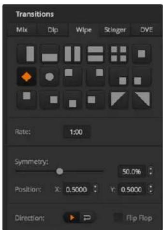
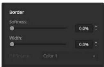
Wipe Transition Settings
To perform a wipe transition on the broadcast panel
1 On the preview bus, select the video source that you want on the program output.
2 Press the WIPE button to select the wipe transition type. The LCD menu will automatically display the transition settings.
NOTE To manually navigate to the wipe patterns menu on an ATEM broadcast panel press HOME > TRANS > WIPE PATTRN.
3 Use the system control menu buttons to select the wipe pattern.
4 Use the system control knobs and buttons to adjust border parameters and specify wipe direction. You can also enter a rate duration using the number pad.
5 Use the select bus to select the border source.
6 Perform the transition as an auto transition or manual transition from the transition control block.
Wipe transition parameters
| Rate | The length of the wipe transition in seconds and frames. |
| Symmetry | Symmetry can be used to control the aspect ratio of the pattern.For example, adjusting the symmetry will allow you to change a circle into an ellipse.On the broadcast panel symmetry can be adjusted using the z axis of the joystick. |
| Position | If the wipe pattern has positioning then the joystick on the broadcast panel or the x position: and y position: boxes in the transition palette of the software control panel can be used to move the center of the pattern. Moving the joystick dynamically updates the x and y position display in the software control panel. |
| Normal | The normal direction for closed patterns such as circles, diamonds and boxes is to grow from the center of the screen and progress outward. |
| Reverse | Reverse changes the progression of closed patterns such as circles, diamonds and boxes so that the pattern closes in from the edges of the screen toward the center. |
| FlipFlop | When FlipFlop mode is toggled on, the transition changes between normal to reverse every time the transition is executed. |
| Border | Width of the border. |
| Soft | The edges of the wipe pattern can be adjusted between sharp and fuzzy by adjusting the softness parameter. |
The border source used in a wipe transition can be any source in the switcher. For example, a thick border with the media player as its source can be used for sponsorship or branding.
ATEM Constellation 8K has no borders for SuperSource in 8K. It has 4 stinger transitions in HD and Ultra HD modes and one in 8K.
On ATEM 1 M/E and 2 M/E switchers, the stinger transition uses a clip from the media player to perform a transition. The clip is normally a graphic animation that is keyed over the background. As the animation plays, when it is full screen, a cut or mix of the background is performed under the animation. For example, this type of transition is very popular in sports productions for transitioning in and out of instant replays. The stinger transition takes advantage of a special keyer that is built into the transition block, leaving all of the upstream and downstream keyers available for compositing your output. The following section explains how to build and perform stinger transitions.
Performing a Stinger Transition
To perform a stinger transition on the software control panel
1 Select the STING transition style button in the transition control block.
2 In the media player palette, select the media you plan to use for the transition.
3 In the transition palette, select the stinger transition type.
4 Select the media player source that has the clip you plan to use.
5 Adjust the clip duration, trigger point, mix rate and pre roll parameters if required.
6 Perform the transition as an auto transition from the transition control block.
You cannot perform a manual stinger transition using the fader bar.
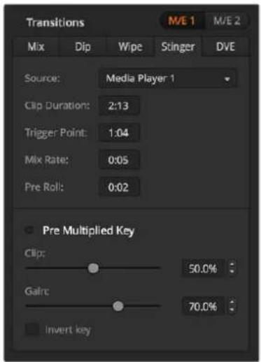
Stinger Transition Settings
Software control panel stinger parameters
| Source | The media player which will be used to play the clip for the animated transition. |
| Clip Duration | Clip duration refers to the length of the animation. The duration should normally match the length of the animation. It can also be used to trim out the end of the clip. |
| Trigger Point | Trigger point is the time at which the switcher will start the background mix transition, which will occur under the animation. Usually, this is the point when the animation is full screen. |
| Mix Rate | The mix rate specifies the duration of the mix that will occur between preview and program under the animation. To specify a cut instead of a mix simply set the rate to 1 frame. |
| Pre Roll | Pre roll is a trim in that can be used to trim the beginning of the clip.The maximum preroll time is 3:00 seconds. |
| Pre Multiplied Key | Identifies the key signal of the media player clip as a pre-multiplied key. |
| Clip | The clip level adjusts the threshold at which the key cuts its hole into the clip that is playing back through the media player. Decreasing the clip level reveals more of the background. If the background video is completely black then the clip value is too low. |
| Gain | The gain adjustment electronically modifies the value which allows the softening of the edges of the key in the clip that is playing back on the media player. Adjust the gain value until the edge softness is desirable but the background video luminance (brightness) is not affected. |
| Invert Key | Inverts the key. |
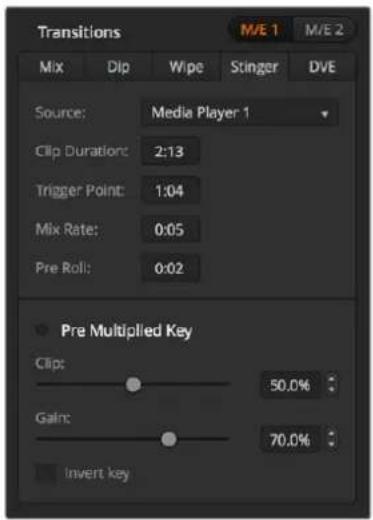
Stinger Transition Settings
To perform a stinger transition on the broadcast panel
1 From the system control menu buttons, navigate to the media player menu by selecting MEDIA PLAYER from the home menu and select the media player you plan to use for the transition.
2 Select the CLIPS button and then use the first knob to select between clips 1 or 2.
3 Select stinger as the transition type by pressing the STNG button on the ATEM 2 M/E Broadcast Panel. On the ATEM 1 M/E Broadcast Panel, pressing the DIP/MIX and DVE/WIPE buttons simultaneously illuminates Both buttons green indicating that the stinger transition type is selected.
4 From the system control menu buttons, select the media player you chose in step 1. You can also navigate to the stinger menu by selecting TRANS > STINGER from the HOME menu.
5 Adjust the preroll, trigger, mix and duration times as needed.
6 Set the logo rate and any other key parameters if required.
7 Perform the transition as an auto transition from the transition control block.
You cannot perform a manual stinger transition using the fader bar.
To perform a stinger transition on the ATEM 1 M/E Advanced Panel
1 Press the 'stinger' transition type button in transition control block.
2 Rotate the LCD menu soft control knob labelled 'source' to select the desired media player.
3 Now that you have set the stinger transition to use the correct media player, press the 'media players' button in the system control menu buttons next to the LCD to configure the media player.
4 In the media players menu, select the still or clip you want to use from the media pool by rotating the 'media' soft control knob. If required, set which frame you want to start the clip from using the corresponding 'frame' soft control knob. Adjust the preroll, trigger, mix and duration times as needed.
NOTE You can also use a HyperDeck as a source for the stinger if you have a HyperDeck connected to your switcher and configured correctly. Refer to the 'HyperDeck control' section of the manual for more information.
5 Perform the transition as an auto transition from the transition control block.
Hardware panel stinger transition parameters
| preroll | Preroll is a trim in that can be used to trim the beginning of the clip.The maximum preroll time is 3:00 seconds. |
| trigger | Trigger is the time at which the switcher will start the background mix transition, which will occur under the animation. Usually, this is the point when the animation is full screen. |
| mix | Mix specifies the duration of the mix that will occur between preview and program under the animation. To specify a cut instead of a mix set the rate to 1 frame. |
| duration | Duration refers to the length of the animation. The duration should normally match the length of the animation. It can also be used to trim out the end of the clip. |
It is important to understand that the trigger, mix and duration times are dependant on one another. For example the trigger + mix rate cannot be larger than the overall duration. Note also that the time displayed in the transition rate window is equal to the overall duration + preroll.
DVE Transitions
ATEM 1 and 2 M/E switchers include a powerful digital video effects processor for DVE transitions. A DVE transition displaces the image in various ways to transition from one picture to another. For example, a DVE transition can be used to squeeze the current picture off screen revealing a new video under it.
ATEM Constellation 8K has 4 DVEs in HD and Ultra HD and one in 8K. These DVEs are without rotation.
To perform a DVE transition on the software control panel
1 On the preview bus, select the video source that you want on the program output.
2 Select the DVE transition style in the transition control block.
3 Expand the transition palette and select DVE from the transition types bar.
If the DVE is being used in an upstream key, the DVE transition style button will be unavailable for selection until the key is taken off air and off next transition. Refer to sharing DVE resources below for more information.
4 Use the settings in the DVE palette to customize the transition.
5 Perform the transition as an auto transition or manual transition from the transition control block.
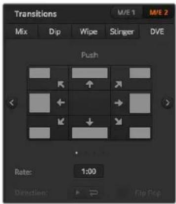
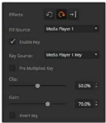
DVE Transition Settings
To perform a DVE transition on the broadcast panel
1 On the preview bus, select the video source that you want on the program output.
2 On the ATEM 2 M/E Broadcast Panel, press the DVE button which illuminates yellow. On the ATEM 1 M/E Broadcast Panel, press the SHIFT and WIPE/DVE buttons to select the DVE transition type. The WIPE/DVE button illuminates green to indicate the DVE transition type is selected. The system control automatically navigates to the DVE pattern menu. To manually navigate to the DVE pattern menu press HOME >TRANS >DVE PATTRN.
If the DVE is already being used in an upstream key, the message DVE unavailable will be displayed and the DVE transition type will not be available for selection until the key is taken off air and off next transition. Refer to sharing DVE resources in the next section for more information.
3 Use the system control menu buttons to select the DVE effects, graphic effects and to enable/disable the DVE Key.
4 Use the knobs and buttons in the system control to customize the DVE transition. You can also enter a DVE rate using the number pad followed by the set rate button.
5 If you are performing a graphic DVE/WIPE, use the select bus to select the logo fill source. Then press the DEST SHIFT or CUT/FILL button, depending upon your model of broadcast panel and use the select bus to select the logo cut source.
6 Perform the transition as an auto transition or manual transition from transition control.
To perform a DVE transition on the ATEM 1 M/E Advanced Panel
1 On the preview bus, select the video source that you want on the program output.
2 Press the DVE transition type button to select the DVE transition. The DVE settings will appear on the LCD menu.
NOTE If the DVE is already being used in an upstream key, the DVE transition type will not be available for selection until the key is taken off air and off next transition. Refer to 'sharing DVE resources' later in this section for more information.
3 In the DVE LCD menu, use the soft control knobs and buttons to configure the DVE parameters. For example, select the DVE pattern, movement, direction and adjust the DVE transition rate.
4 Perform the transition as an auto or manual transition using the auto button or fader bar.
DVE transition parameters
| DVE Rate | The duration of the DVE transition in seconds and frames. Rotate the DVE rate knob to adjust the DVE transition rate. The new rate is immediately displayed in the transition rate window in the transition control block. |
| Normal | The normal direction applies the DVE effect on program, revealing the preview channel. |
| Reverse | Reverse changes the direction so that the DVE effect is applied on the preview channel. In the case of reverse, program is covered by a DVE effect with the preview video. |
| FlipFlop | When FlipFlop mode is toggled on, the transition changes between normal and reverse every time the transition is executed. |
DVE key parameters
| Enable key | Enables/disables the DVE key. The DVE key is enabled when the button is illuminated. |
| PreMult | Selects the DVE key as a pre-multiplied key. |
| Clip | The clip level adjusts the threshold at which the key cuts its hole. Decreasing the clip level reveals more of the background. If the background video is completely black then the clip value is too low. |
| Gain | The gain adjustment electronically modifies the angle between on and off thereby softening the edges of the key. Adjust the gain value until the edge softness is desirable but the background video luminance (brightness) is not affected. |
| Inverse | When the key is not pre-multiplied, inverts the key signal. |
Sharing DVE resources
ATEM features a DVE channel which can be used to perform DVE transitions or used in an upstream keyer. When you select a DVE transition, if the DVE is used elsewhere in the system, the DVE transition type will not be available and, on the broadcast panel, a DVE unavailable message will be displayed. In order to use the DVE transition you must free the DVE from where it is currently used. Verify that the upstream keys currently on program or preview are not DVE keys and do not have fly key enabled. To free DVE from the upstream keyer, change the key type to anything other than DVE or disable fly key. The DVE will be released and therefore available for use as a DVE transition.
The graphic transition is a popular transition that uses the DVE and moves a graphic across the screen over a background transition. For example, the graphic wipe moves a graphic over a horizontal wipe, essentially replacing the wipe border. A graphic mix spins the graphic across the screen over a mix transition. Graphic transitions are perfect for wiping the station logo or spinning a football across the screen revealing a new background. Graphic transitions use a special keyer built into the transition block, leaving all of the upstream and downstream keyers available for compositing the output. The following section explains how to build and perform graphic transitions.
The above image sequence provides an example of the program output for a graphic wipe transition.
Performing a Graphic Transition
To perform a graphic transition on the software control panel
1 Select the DVE transition style button in the transition control block.
If the DVE is being used in an upstream key, the DVE transition style button will be unavailable for selection until the key is taken off air and off next transition. Refer to sharing DVE resources in the next section for more information.
2 Expand the transition palette and select the DVE transition type. Use the previous or next arrows to select a different DVE type.
3 From the graphic effects: buttons, select one of the graphic effects buttons.
4 Select the fill source and key source for the graphic from the drop down list.
5 Adjust the key parameters if required.
6 Perform the transition as an auto transition or manual transition from the transition control block.
To perform a graphic transition on the broadcast panel
1 On the ATEM 2 M/E Broadcast Panel, press the DVE button which illuminates yellow. On the ATEM 1 M/E Broadcast Panel, press the SHIFT and WIPE/DVE buttons to select the DVE transition type. The WIPE/DVE button illuminates green to indicate the DVE transition type is selected.
If the DVE is already being used in an upstream key, the message DVE unavailable will be displayed and the DVE transition type will be unavailable for selection until the key is taken off air and off preview. Refer to sharing DVE resources in the next section for more information.
2 From the system control menu buttons, push next until you are on the DVE Graphics menu. You can also navigate to the DVE menu by selecting TRANS > DVE PATTRN from the home menu and repeatedly pushing 'Next' to get to the DVE Graphic page.
3 Select one of the two graphic mix buttons, depending on which way you want your graphic to spin across the screen.
4 Select the logo fill source and logo key source for the graphic from the select bus.
5 Set the rate and any other key parameters if required.
6 Perform the transition as an auto transition or manual transition from the transition control block.
To perform a graphic transition on the ATEM 1 M/E Advanced Panel
1 Press the DVE transition type button in the transition control block. The DVE settings menu will appear on the LCD.
If the DVE is already being used in an upstream key, the DVE transition type will not be available for selection until the key is taken off air and off next transition. Refer to 'sharing DVE resources' later in this section for more information.
2 Press the 'effect' soft button in the LCD menu to open the effect settings and set the effect to a graphic wipe by selecting the graphic wipe icon using the 'effect' soft control knob.
The default direction is left to right, but you can change the direction by selecting 'reverse direction'. You can also enable 'flip flop' which will let the effect move forwards and backwards with each performance of the transition, rather than repeating the same movement direction.
3 Press the right arrow in the system control buttons to adjust the key settings. Enable the key and select the fill and key source. If you need to make adjustments to the key, for example adjusting clip and gain settings, press the right arrow in the system control buttons to access the key parameters.
TIP Typically, for a graphic transition, the source would normally be a graphic loaded in a media player. By default, when you select a media player for the fill source, the key source will automatically select the media player key channel and set pre multiplied key to 'on'. This means a graphic with a key matte embedded in the alpha channel will automatically be selected by the switcher. You can disable pre multiplied key and change the key source if you want to use a separate media file on a different media player, or a different input source.
4 Press the auto button to perform the transition as an auto transition, or use the fader bar for a manual transition.
Description of graphic wipe parameters
| Rate | Rate specifies the length of the transition in seconds and frames. The rate can be adjusted using the rate knob or by entering a number on the number pad and pressing the set rate button. |
| Normal | The normal direction moves the graphic from left to right. |
| Reverse | Reverse changes the direction so that it moves the graphic from right to left. |
| FlipFlop | When FlipFlop mode is toggled on, the transition changes between normal and reverse every time the transition is executed. The ‘Normal’ or ‘Reverse’ light indicates the direction of the next transition. |
| Fill Source | The fill signal is the graphic used to move across the top of the transition. |
| Key Source | The key signal is a grayscale image that defines the region in the graphic that will be removed so that the fill signal can be correctly stacked on top of the wipe. |
Sharing DVE resources
The one DVE channel available in the switcher can be used to perform DVE transitions or it can be used in an upstream keyer. When you select a DVE transition, if the DVE is used elsewhere in the system, the DVE transition type will not be available and, on the broadcast panel, a DVE unavailable message will be displayed. In order to use the graphic wipe transition you must free the DVE from where it is currently used. Verify that the upstream keys currently on program or preview are not DVE keys and do not have fly key enabled. To free DVE from the upstream keyer, change the key type to anything other than DVE or disable fly key. The DVE will be released and therefore available for use as a graphic wipe.
Graphic wipe images
The graphic wipe feature requires a static graphic that is used as a moving border for a horizontal wipe. This graphic should be a vertical 'banner' type graphic that is no more than 25% of the total screen width.
natural_image
Pure black background with a small bright light source in the corner (no text or symbols)
natural_image
Completely black image with a faint white glow at the top left corner (no text or symbols)Graphic wipe screen width requirements
| 4320p | If the switcher is operating at 4320p then the graphic should be no wider than 1920 pixels. |
| 2160p | If the switcher is operating at 2160p then the graphic should be no wider than 960 pixels. |
| 1080i | If the switcher is operating at 1080i then the graphic should be no wider than 480 pixels. |
| 720p | If the switcher is operating at 720p than the graphic should be no wider than 320 pixels. |
| SD | If the switcher is operating in Standard Definition then the graphic then the graphic should be no wider then 180 pixels. |
Manual Transitions
Manual transitions let you manually transition between program and preview sources using the fader bar in the transition control block. Mix, dip, wipe and DVE transitions can all be performed as a manual transition.
To perform a manual transition on the software control panel or ATEM hardware panel:
1 On the preview bus, select the video source that you want on the program output.
2 Select the transition type using the transition type buttons in the transition control block.
3 Manually move the fader bar from one end to the other to execute the transition. The next fader bar move will begin a new transition.
4 During the transition the red and green buttons on the program and preview buses both turn red to indicate that you are in the middle of a transition. On the broadcast panel, the fader bar indicator also displays the position and progress of the transition. On the software control panel, the virtual fader bar displays the position and progress of the transition.
5 At the end of the transition sources selected on the program and preview buses are exchanged to indicate that the video source that was on preview is now on program and vice versa.
Preview Transition
ATEM switchers have a powerful feature which allows you to review and adjust a transition on the preview output. The preview transition mode lets you verify a transition before actually performing it on air.
To preview a transition on the software control panel or ATEM hardware panel:
1 On the preview bus, select the video source that you want on the program output.
2 Select the transition type using the transition type buttons in the transition control block.
3 Press the PREV TRANS button to put the switcher into preview transition mode. The PREV TRANS button will illuminate red and the preview output will change so that it is a copy of the program output.
4 Manually move the fader bar from one end to the other to preview the transition on the preview output. The program output will remain unchanged.
5 Press the PREV TRANS button or return the fader bar to its starting position to turn off preview transition mode. Returning the fader bar to its starting position will automatically disable preview transition mode and turn off the red light on the PREV TRANS button. Moving the fader bar after the light is off will take the transition on the program output.
Keying using ATEM Switchers
Keyers are a powerful production tool that allows the arrangement of visual elements from different sources on the same video image.
To do this, multiple layers of video or graphics are stacked on top of the background video. Altering the transparency of various parts of these layers allows the background layer to be visible. This process is called keying. Various techniques are used to create this selective transparency and these correspond to the different types of keyers available on your switcher.
The following section explains luma and linear keyers, which are available either upstream or downstream. It also explains chroma, pattern and DVE keys, which are upstream keyers.
TIP Some ATEM switcher models, such as ATEM 4 M/E Broadcast Studio 4K offer additional chroma keying options. For more information, see the 'performing an advanced chroma key' section in this manual.
Understanding Keying
A key requires two video sources; the fill signal and the key or cut signal. The fill signal contains a video image which is to be stacked on top of the background, while the key signal is used to select regions of the fill signal to be made transparent. The fill and key signals can be selected from any of the switcher's external inputs or internal sources, allowing both still and moving images to be used as fill or key sources.
Fill and key signals are selected on the software control panel from drop down lists in the upstream and downstream key palettes. On the broadcast panel, fill and key signals are selected using the select bus.
There are two types of keyers used in the switcher; upstream keyers and downstream keyers. Four upstream keyers, also known as effects keyers, are available in the switcher's M/E block. Each upstream keyer can be set up as a luma, linear, pre-multiplied, chroma, pattern or DVE key. Two downstream keyers are available in the dedicated DSK block. Each downstream keyer can be set up as a luma or linear key.
On DVEs and upstream keys using DVEs, you can also select the ME 2 program or preview output as the DVE fill source. This gives you a tremendous amount of creative options when keying.
ATEM 4 M/E Broadcast Studio 4K lets you output your key mask via powerful 12G-SDI auxiliary outputs, or 6G-SDI outputs on ATEM Production Studio 4K models. It's as simple as pressing the KEY MASK button on the front panel. You can also access your media player 1 and 2 image and key sources by pressing their associated buttons on the front panel. With the key mask feature you can record your key mask, or alpha channel, in SD, HD or Ultra HD quality via the auxiliary output. You can also record your green screen video via the program output at the same time. Recording both sources is useful if you require detailed chroma key post production effects.
Luma Key
A luma key or self key consists of one video source containing the video image that will be stacked on top of the background. All of the black areas defined by the luminance in the video signal will be made transparent so that the background can be revealed underneath. Since only one image is used to define the areas to be cut out, a luma key uses the same signal for fill and key. The following images are an example of what background, luma key signals and the resulting combined image might look like.
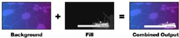
Combining a background and fill/key in a luma key
Background - a full screen image, often a camera source.
Fill - the graphic you plan to display on top of your background video. Notice that the final composition does not retain any black from the graphic because all of the black parts have been cut out of the image.
Linear Key
A linear key consists of two video sources; the fill signal and the key or cut signal. The fill signal contains a video image which is to be stacked on top of the background, while the key signal contains a grayscale mask that is used to define regions of the fill signal to be made transparent. Since both the fill and key signals are video inputs, both signals can be in motion while on screen. The following images are examples of what background, fill, key signals and the resulting combined image might look like.

Combining a background, fill and key in a linear key
Background - a full screen image, often a camera source.
Fill - the graphic you plan to display on top of your background video. Notice that the black parts of the graphic remain intact because the key signal is used to determine the transparency of the fill signal. The fill signal is often provided by a graphics system.
Key - a grayscale image that defines the region in the image that will be removed so that the fill signal can be correctly stacked on top of the background. The key signal is often provided by a graphics system.
Pre multiplied Key
A modern graphics system or character generator that offers fill and key outputs will most likely provide what is known as a pre-multiplied or shaped key. A pre-multiplied key is a special combination of the fill and key signal where the fill signal has been pre-multiplied with the key signal over a black background. Photoshop generated images that contain an alpha channel are pre-multiplied.
ATEM switchers have an auto key adjustment for pre-multiplied keys so that when the pre-multiplied key setting is enabled, the clip and gain parameters are automatically set by the system.
When using a Photoshop generated image, generate graphics over a black background layer and place all content on the upper layers. Add an alpha channel in your Photoshop document that the ATEM can use for blending the graphic over the live video. Then, when saved as a Targa image file, or downloaded direct to the media pool, you can select pre-multiplied in the keyer and you should have a great key!
Photoshop documents are pre-multiplied by nature, so you should always use the pre-multiplied settings on the ATEM switcher when keying them.
Performing an Upstream Luma/Linear Key
Since luma and linear keys use the same parameters, they are set up on the software control panel and broadcast panel using a common menu, called the luma key menu. What defines the key as being either luma or linear is in the selection of fill and key sources. In a luma key, fill and key sources are the same. For a linear key, fill and key sources are different.
The Upstream Key palette has a menu for resetting parameters at the top of each tab. Select the sections you wish to reset from the menu.
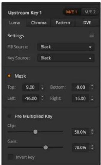
Luma Key Settings
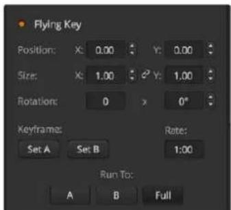
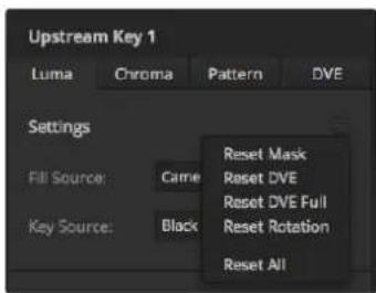
Select sections of the Palette you wish to reset from the reset menu
To set up a luma/linear key on upstream keyer 1 on the software control panel:
1 Expand the upstream key 1 M/E 1 palette and select luma tab.
2 Select the fill source and key source.
If performing a luma key, select the same source for both fill and key.
Adjust the key parameters to refine the key. For a description of luma key parameters, refer to the table below.
To set up a luma/linear key on upstream keyer 1 on the broadcast panel:
1 Press the KEY 1 button in the transition control block to enable the keyer on the preview output. The system control will dynamically navigate to the KEY 1 menu. You can manually navigate to the KEY 1 menu by pressing HOME > EFFECTS KEYS > KEY 1.
2 Select the LUMA KEY menu button.
3 The destination display on the ATEM 1 M/E Broadcast Panel will say key1fill. Select the fill source on the select bus.
4 On the ATEM 2 M/E Broadcast Panel, hold down the KEY1/CUT button and select the key source. On the ATEM 1 M/E Broadcast Panel, hold down the CUT/FILL button so the destination display says key1 cut and select the key source.
If performing a luma key, select the same source for both fill and key.
5 Adjust the clip and gain controls to refine the key or select 'Pre Multiplied Key' for pre-multipled keys. The clip and gain are set automatically for pre-multipled keys.
To set up a luma/linear key on upstream keyer 1 on the ATEM 1 M/E Advanced Panel:
1 Press the 'key 1' button to enable the keyer on the preview output. This automatically selects the keyers menu on the system control LCD, but you can also press the 'keyers' button to enter the menu directly.
2 Select the desired M/E keyer by pressing the corresponding soft button along the top edge of the LCD menu.
3 Use the control knob underneath the 'key type' indicator to choose the 'luma' key.
4 Rotate the 'fill source' and 'key source' control knobs to choose a fill and key source.
TIP You can also press the corresponding buttons on the source select bus to select the fill and key source.
5 Once you have chosen a key type, fill and source, press the 'right' arrow button to scroll through to the next menu item and use the control knobs to adjust key parameters such as mask, gain, clip, enable or disable pre multiplied key, etc.
Upstream key luma/linear key parameters:
| Mask | Enables a rectangular mask that can then be adjusted using the top, bottom, left and right parameters. |
| Pre-Mult | Identifies the key signal as a pre-multiplied key. |
| Clip | The clip level adjusts the threshold at which the key cuts its hole. Decreasing the clip level reveals more of the background. If the background video is completely black then the clip value is too low. |
| Gain | The gain adjustment electronically modifies the angle between on and off thereby softening the edges of the key. Adjust the gain value until the edge softness is desirable but the background video luminance or brightness is not affected. |
| Invert Key | Inverts the key signal. |
| Flying Key | Enables/disables DVE effects. |
Performing a Downstream Luma/Linear Key
To set up a luma/linear key on downstream keyer 1 on the software control panel:
1 Select the downstream key 1 palette.
2 Use the drop down controls labeled fill source and key source to specify the fill and key sources. If performing a luma key, select the same source for both fill and key.
3 Adjust the key parameters to refine the key.
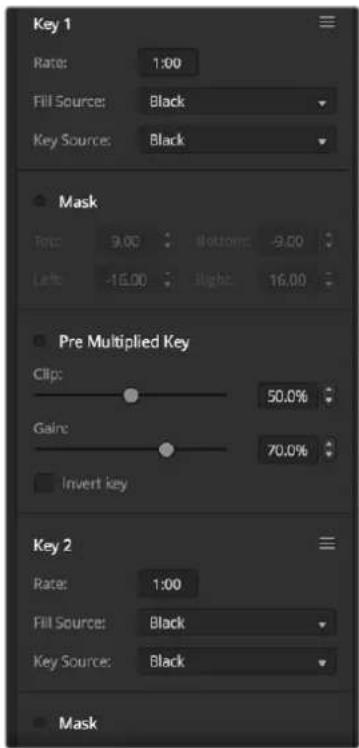
Downstream Keyer Settings
To set up a luma/linear key on downstream keyer 1 on the broadcast panel:
1 Press the DSK 1 TIE button to enable the downstream keyer on the preview output. The M/E 1 system control will dynamically navigate to the DSK 1 menu. You can manually navigate to the DSK 1 menu by pressing HOME > DSK KEYS > DSK 1.
2 The destination display will say DSK1 fill on the On the ATEM 1 M/E Broadcast Panel. Select the fill source on the select bus.
3 On the ATEM 2 M/E Broadcast Panel, hold down the DEST SHIFT button and select the key source on the select bus. On the ATEM 1 M/E Broadcast Panel, hold down the CUT/FILL button so the destination display says DSK1 cut and select the key source on the select bus.
If performing a linear key, select the same source for both fill and key.
4 Adjust the clip and gain controls to refine the key or press the pre-mult button for pre-multipled keys. The clip and gain controls are not available for pre-multipled keys.
To set up a luma/linear key on downstream keyer 1 on the ATEM 1 M/E Advanced Panel:
1 Press the 'DSK 1 tie' button to enable the downstream keyer on the preview output. This automatically selects the downstream key menu on the system control LCD, but you can also press the 'keyers' button and press the right arrow to enter the menu directly.
2 Press the 'DSK 1' or 'DSK 2' soft button to select which downstream keyer you wish to use.
TIP You don't have to select the key type as the downstream keyer is always a luma key.
3 Use the control knobs under the LCD menu to select the fill source and key source. You can also use the corresponding source select buttons to select the fill and key source.
4 Once you have chosen the fill source and key source, use the 'left' and 'right' control buttons to scroll through additional menu screens containing key parameters such as mask, gain, clip, pre multiplied key settings and more.
Chroma Key
Chroma key is commonly used for weather broadcasts, where the meteorologist appears to be standing in front of a large map. In the studio the presenter is actually standing in front of a blue or green background. In a chroma key two images are combined using a special technique and a color from one image is removed, revealing another image behind it. This technique is also referred to as color keying, color-separation overlay, green screen, or blue screen.
A very common use for chroma keys for backgrounds is computer generated graphics. It's simple to connect an external computer to your ATEM switcher using the HDMI output of the computer or a video card such as the Blackmagic Design DeckLink or Intensity range and then play back video clips to your ATEM switcher. If you render a green background on your animations, you can then key this green to create fast and clean animations of any length.
Keying is easy as the green is computer generated so it's a very flat color that's easy to key.

Combining a background with a fill and chroma key/cut
Background - a full screen image; in the case of a chroma key it is often a weather map.
Fill - the image you plan to display on top of your background video. In the case of a chroma key, this is video of the meteorologist in front of the green screen.
Key/Cut - In the case of a chroma key the key/cut signal is generated from the fill signal.
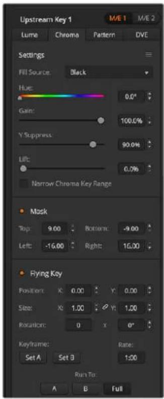
Chroma Key Settings
Performing an Upstream Chroma Key
Use the following steps to perform a chroma key on ATEM Switchers. ATEM 4 M/E Broadcast Studio 4K has its own unique chroma keyer with advanced controls. For more information, refer to 'Performing an Advanced Chroma Key' later in this section.
To set up a chroma key on upstream keyer 1 on the software control panel:
1 Expand the upstream key 1 M/E 1 palette and select chroma from the key types bar.
2 Select the fill source.
3 Adjust the key parameters to refine the key. For a description of chroma key parameters, refer to the table below.
To set up a chroma key on upstream keyer 1 on the broadcast panel:
1 Press the KEY 1 button to enable the keyer on the preview output. The system control will dynamically navigate to the KEY 1 menu. You can manually navigate to the KEY 1 menu by pressing HOME > EFFECTS KEYS > KEY 1.
2 Select the CHROMA KEY menu button.
3 On the ATEM 1 M/E Broadcast Panel, the destination display will say keyfill. On the ATEM 2 M/E Broadcast Panel, the KEY 1/CUT button will be lit. Select the fill source on the select bus.
4 Adjust the chroma key controls to refine the key.
To set up a chroma key on upstream keyer 1 on the ATEM 1 M/E Advanced Panel:
1 Press the 'key 1' button to enable keyer 1 on the preview output. This automatically selects the keyers menu on the system control LCD, but you can also press the 'keyers' button to enter the menu directly.
2 Select the 'chroma' key type using the corresponding 'key type' control knob.
3 Select your fill source by turning the corresponding LCD control knob. You can also select a fill source by pressing the corresponding button in the source select bus.
4 Use the 'left' and 'right' arrow buttons to access additional key parameters you may want to adjust such as hue, gain, y suppress, lift and masking.
TIP When making adjustments on ATEM 1 M/E Advanced Panel, you can restore all settings to their defaults by holding down the shift key and pressing 'reset'. To reset individual parameters, hold down the shift key and press the corresponding soft control knob.
| Hue | The hue adjustment selects the color that will be replaced. Rotate the hue knob until the background keys through the desired color. |
| Gain | The gain adjustment determines how the colors around the selected hue are keyed. Adjust the gain knob until the edges of the keyed region appear the way you want them. |
| Y Suppress | Adjust this knob until the black level of the chroma removed region is correct. |
| Lift | Lift should normally be set to zero for a well set up chroma key scene. Lift allows very low saturation values of the keyed color to be excluded from the key. Colored light spilling onto a neutral colored object in the foreground will sometimes cause small areas to key to the background source. Lift allows you to fill these small holes in the key signal. |
| Narrow | The acceptance angle of colors around the selected hue should generally be as broad as possible to achieve natural looking chroma Keys. Sometimes, if some colors in the fill source are too close to the chroma key color, it may be hard to exclude them from the key. Selecting the narrow button uses a smaller acceptance angle around the chroma key color. Selecting narrow temporarily, may help you center the hue adjustment. |
| Flying Key | Enables/disables DVE effects. |
Adjusting parameters with a vectorscope
You may wish to set up a chroma key using color bars as the background source and watching the result on a vector scope as you perform the following procedure.
1 Turn narrow off.
2 Set lift to 0.
3 Adjust the hue until the color hex dots are centered around black. Adjusting the hue knob will offset the black point and the constellation of the 6 color bar dots will rotate around the screen.
4 Adjust the gain until the color bars are near their target boxes on the vector scope. Adjusting the gain will expand and contract the color vectors about the center.
5 Adjust the Y Suppress knob until the black level is correct.
Performing an Advanced Chroma Key
ATEM Constellation 8K and ATEM 4 M/E Broadcast Studio 4K feature advanced chroma keying, with more detailed chroma sampling and adjustment options. These controls help you achieve the best key, improving the blend of foreground and background so you can create a more convincing visual effect.
TIP ATEM 2 M/E Broadcast Studio 4K can be upgraded to ATEM 4 M/E Broadcast Studio 4K with a free software update. Simply install ATEM software version 7.3 or later as detailed in the “updating the software” section in this manual.
To set up a chroma key on upstream key 1 on the software control panel:
1 Expand the upstream key 1 M/E 1 palette and select 'chroma' from the key types bar.
2 Select the fill source. Typically, this source would be from a camera facing a presenter in front of a green screen, or a graphic loaded in a media player.
3 Click the 'chroma sample' button.
With the chroma sample selected, you'll see a new panel appear with a box cursor. This cursor is also visible on the M/E 1 preview output.
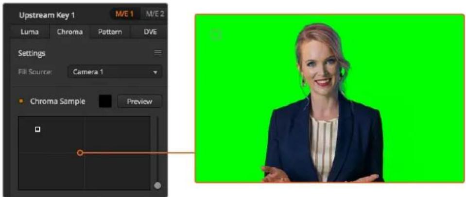
The chroma sample setting lets you position a cursor over the screen area you want to sample
TIP You can also view the M/E 1 preview output on your switcher's front control panel LCD by pressing one of the auxiliary output buttons, then pressing the ME 1 PVW button.
4 Click and drag on the box cursor to move it to the position you want to sample.
Choose a representative area of your green screen that covers as much of the luminance range of the screen as possible. The default size of the box cursor is well suited to most green screens that are relatively evenly lit, however if there is a lot of variance in your green screen, you can adjust the size of the box by clicking on the slider to the right of the sample window and dragging it up or down.
TIP When sampling uneven green screens, we recommend sampling the darkest area first before increasing the size of the sample box. This can give you a more accurate key.
You can preview your key at any time by clicking the 'preview' button above the chroma sample panel.
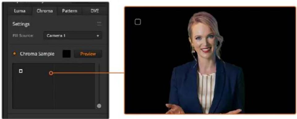
Use the preview button to check what your key will look like in the M/E 1 PVW output
Fine Tuning your Key using Key Adjustments
Once you have achieved a good chroma sample that removes most of your green screen while generally retaining foreground elements, its time fine tune your key with the 'key adjustments' controls.
Foreground
Use the 'foreground' slider to adjust how opaque the foreground mask is. This determines the strength of the foreground against the background. By increasing the slider, you can fill in any small areas of transparency inside your foreground image. We recommend moving this slider and stopping as soon as the foreground becomes solid.
Background
The 'background' slider adjusts the opacity of the keyed area. Use this slider to fill in any small foreground artifacts left over in the area of the image you want to remove. We recommend moving the slider until your keyed area is consistently opaque.
Key Edge
The "key edge" slider moves the edge of your keyed area in or out, helping to remove background elements from the very edge of your foreground or extending the foreground out a little if your key is too aggressive. This can be especially useful with fine details like hair. We recommend moving this slider until the edge of your key is generally clean, without any background artifacts visible.
Using the key adjustment controls, your foreground elements should be cleanly separated from the background.
While making key adjustments, it can be useful to assign one of your multi view windows to show your key mask. For example, if your performing a chroma key on M/E 1, set one of the outputs to "ME 1 KEY MASK 1." This will give you a clearer view of your key for fine adjustments.
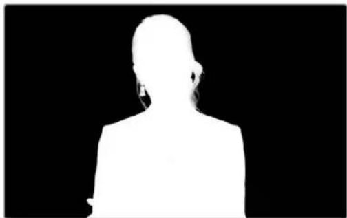
natural_image
Silhouette of a person in formal attire against a black background (no text or symbols)Displaying your key mask in a separate MultiView window can make fine tuning a key much easier.
Chroma Correction using Color Spill and Flare Suppression
Light bouncing off a green screen can create a green edge to foreground elements as well as a general tint to the foreground, or fill image. This is called color spill and flare. The 'chroma correction' settings let you improve the areas of the foreground that are affected by color spill and flare. You can correct these areas in the key using the 'chroma correction' settings.
Spill
Adjust the spill slider to remove colored tint from the edges of foreground elements.
For example, green reflections bouncing off a green screen.
Flare Suppression
Flare suppression removes overall green tint evenly across all foreground elements.
Matching your foreground and background
Once your foreground is properly separated from your green screen and you have adjusted spill and flare suppression, use the 'color adjustments' controls to match your foreground with the background.
Adjusting the brightness, contrast, saturation and color balance of your foreground image will help blend it with the background so the effect is more convincing.
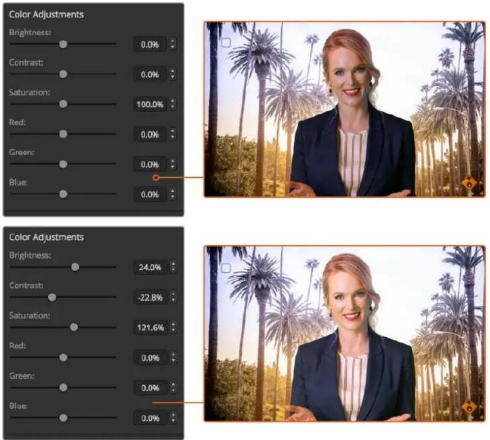
Use the color adjustments controls to match your foreground with the background
Pattern Key
A pattern key is used to display a geometric cut out of one image on top of another image. In a pattern key the key or cut signal is generated using the switcher's internal pattern generator. The internal pattern generator can create 18 shapes that can be sized and positioned to produce the desired key signal.

Combining a background with a fill and pattern key
Background - A full screen image.
Fill - Another full screen image you wish to overlay on top of the background.
Key/Cut - In the case of a pattern key the key/cut signal is generated by the switcher's internal pattern generator.
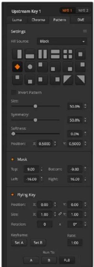
Pattern Key Settings
Performing an Upstream Pattern Key
To set up a pattern key on upstream keyer 1 on the software control panel:
1 Expand the upstream key 1 M/E 1 palette and select pattern from the key types bar.
2 Select the fill source.
3 Select the key pattern.
4 Adjust the key parameters to refine the key. For a description of pattern key parameters, refer to the table below.
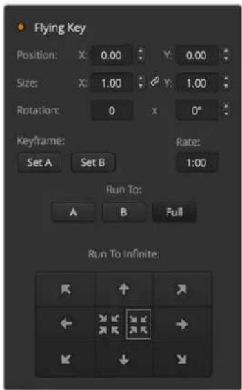
Pattern Key Settings
To set up a pattern key on upstream keyer 1 on the broadcast panel:
1 Press the KEY 1 button to enable the keyer on the preview output. The system control will dynamically navigate to the KEY 1 menu. You can manually navigate to the KEY 1 menu by pressing HOME > EFFECTS KEYS > KEY 1.
2 Select the PATTRN KEY menu button.
3 The destination display will say key1fill on the ATEM 1 M/E Broadcast Panel. On the ATEM 2 M/E Broadcast Panel, the KEY 1/CUT button will be lit. Select the fill source on the select bus.
4 Select the PATTRN MENU button and use the menu buttons to select a pattern.
5 Adjust the pattern key controls to refine the key.
To set up a pattern key on upstream keyer 1 on the ATEM 1 M/E Advanced Panel:
1 Press the KEY 1 next transition button to enable the key on the preview output. This automatically selects the keyers menu on the system control LCD. Pressing the KEY 1 next transition button ties the key to the next transition so it will transition to air when the next transition is performed.
2 In the keyers LCD menu, select the 'pattern' key type using the corresponding 'key type' control knob.
3 Select the fill source using the corresponding soft control knob or by pressing a source button on the source select bus.
4 Turn the corresponding soft control knobs to choose the 'pattern' you want for the pattern key and set the 'size' of the pattern.
5 Press the system control left and right arrow buttons to navigate through the pattern key parameters and adjust settings using the control knobs. Watch the preview output as you refine the key.
TIP Some patterns can have their center point repositioned. Use the joystick to move the position of the pattern. If you need to reset the position, navigate to the 'pattern type' setting, change it to another pattern and then return to your chosen pattern to reset the position to its default.
| Size | Increases and decreases the size of the selected pattern. |
| Symmetry | Some patterns may have their symmetry or aspect ratio adjusted. Circle patterns may be adjusted to become horizontal or vertical ellipses. Twist the joystick knob to adjust its symmetry. |
| Soft | Changes the softness of the edge of the key signal. |
| Inverse | This button inverts which the region filled with the fill source. For example, fill a region outside of a circle by positioning the circle wipe as desired and then selecting inverse. |
| Flying Key | Enables/disables DVE effects |
Adjusting the x/y position of a pattern
Some of the patterns may have their center point repositioned. To position a pattern, navigate to the pattern selection page of the keyer you are setting up. Use the joystick to move the pattern vertically and horizontally. To re-center the pattern, press the pattern select button of the current pattern in the menu. This will reset the position and symmetry of the pattern.
DVE Key
DVEs (digital video effects) are used to create picture-in-picture boxes with borders. Most models have 1 channel of 2D DVE that allows scaling, rotation, 3D borders and offers a drop shadow.

Combining a background, DVE fill and DVE key/cut
Background - A full screen image.
Fill - Another full screen that has been scaled, rotated or has added borders and will be overlaid on top of the background.
Key/Cut - In the case of a DVE key, the key/cut signal is generated by the switcher's internal DVE processor.
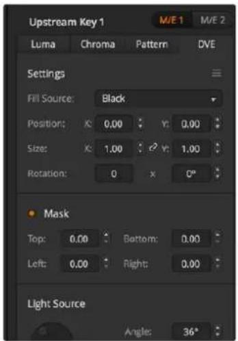
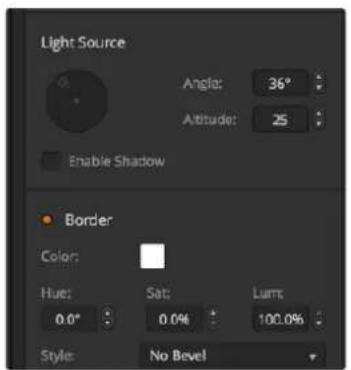
DVE Key Settings
Performing an Upstream DVE Key
To set up a DVE key on upstream keyer 1 on the software control panel:
1 Expand the upstream key 1 M/E 1 palette and select DVE from the key types bar.
2 Select the fill source. You can even select the ME 2 program or preview output as the DVE fill source which gives you a tremendous amount of control and creative options.
3 Adjust the key parameters to refine the key. For a description of DVE key parameters, refer to the table below.
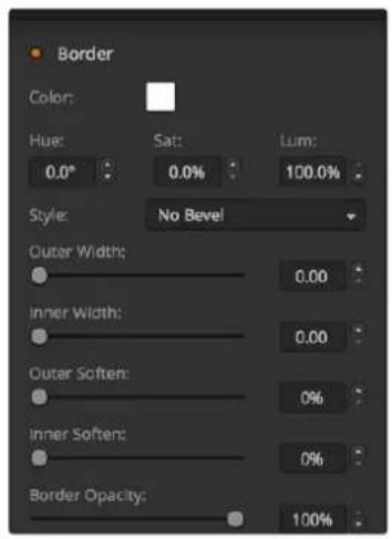
DVE Key Settings
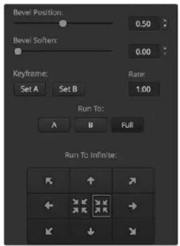
To set up a DVE key on upstream keyer 1 on the broadcast panel:
1 Press the KEY 1 next transition button to enable the keyer on the preview output. The system control will dynamically navigate to the KEY 1 menu. You can manually navigate to the KEY 1 menu by pressing HOME > EFFECTS KEYS > KEY 1.
2 Select the DVE menu button.
3 The destination display will say keyfill on the ATEM 1 M/E Broadcast Panel. On the ATEM 2 M/E Broadcast Panel, the KEY 1/CUT button will be lit. Select the fill source on the select bus.
4 To enable the mask and adjust the mask parameters, select the MASK MENU button.
5 To enable the drop shadow or border and adjust their parameters, select the 'enable shadow' checkbox, then adjust the angle and altitude settings by clicking and dragging the 'light' icon. Refer to the table below.
To set up a DVE key on upstream keyer 1 on the ATEM 1 M/E Advanced Panel:
1 Press the KEY 1 next transition button to enable the keyer on the preview output.
2 In the keyers LCD menu, select the DVE key type using the corresponding soft control knob.
3 Select the fill source using the corresponding control knob or via the a source button on the source select bus.
4 Press the system control left and right arrow buttons to navigate through the DVE parameters and use the soft control knobs to adjust settings, such as rotation, position, size, mask settings, light source, border and key frames for movement.
TIP When using the number pad to enter numeric values for settings, hold the 'reset' button down for several seconds to enable negative values. Hold down again to return to standard values.
DVE parameters
| X Size | Adjusts the horizontal size of the DVE. |
| Y Size | Adjusts the vertical size of the DVE. |
| Rotation | Spin the box around its center point with the Rotation adjustment knob. |
| Rot Rst | Resets the rotation of the DVE. |
| DVE Rst | Resets the DVE to screen. Useful if you lose track of the DVE during adjustment. |
Adding DVE Borders
DVE border styles
The 3D borders used in the upstream keyers have four different style settings. The style settings adjust the overall look of the border.
| No Bevel | No bevel - 2D border where the border width, softness and color adjustments are applicable. |
| Bevel In Out | Bevel in out - 3D border |
| Bevel Out | Bevel out - 3D border |
| Bevel In | Bevel in - 3D border |
DVE border parameters
The knobs and soft buttons in the system control are used to adjust the border parameters. There are multiple parameters, each requiring an adjustment, therefore the soft/color button and SHIFT button is used to toggle the parameters that each knob adjusts.
| Border | Enables or disables the border. |
| Shadow | Enables or disables drop shadow. |
| Soft/Color | This control is toggled between these two color settings (including light direction) and softness settings (including size). Capital letters indicate which settings are currently selected for control. |
| Out Width | Adjusts the outside width of the border. |
| Out Soft | Outside softness adjusts the outside edge of the border, the edge that touches the background video. |
| Bevel Soft | Bevel softness adjusts the overall softness of the 3D border. A high value for this parameter will result in a rounded or beveled border. |
| Opacity | Opacity adjusts the transparency of the border, use this setting to create interesting colored glass borders. |
| Hue | Changes the border color. The hue value is a location on the color wheel. |
| Sat | Changes the intensity of the border color. |
| Luma | Change the brightness of the border color. |
| Light Angle | Adjusts the direction of the light source on the DVE or picture in picture. Both the border and drop shadow, if available, are affected by changes to this setting. |
| In Width | Adjusts the inside width of the border. |
| In Soft | Adjusts inside softness. This softness parameter adjusts the inside edge of the border, the edge that touches the video. |
| Bevel Pos | Adjusts the position of the 3D bevel on the border. |
| Light Altitude | Adjusts the distance of the light source from the DVE or picture in picture. Both the border and drop shadow, if available, are affected by changes to this setting. |
Key Masking
Both upstream and downstream keyers have an adjustable rectangular mask that can be used to crop out harsh edges and other artifacts in the video signal. The mask consists of left, right, top and bottom crop controls. Masking can also be used as a creative tool to build rectangular cut outs on screen.
On the broadcast panel the mask is set up for each upstream and downstream key from the system control mask menu which is available from the EFFECTS KEYS or DSK KEYS menus.
On the software control panel the mask is set up for each upstream or downstream key from the palettes in the settings tab.
Fly Key
Luma, chroma and pattern upstream key types include a fly key setting. If a DVE channel is available the Fly Key setting allows DVE effects to be applied to the key.
Performing Upstream Keyer Transitions
The upstream keyers are accessible from the transition control block or the system control. The upstream keyers are taken on and off the program output using the next transition buttons or ON buttons.
ON buttons
Take the upstream keyers on or off the program output using the ON (on air) buttons as follows:
1 Press the ON button above the corresponding next transition KEY button to immediately turn on or turn off the upstream key on the program output.
2 The ON button also indicates if the upstream keyer is currently on or off the program output.
Next transition buttons
Take the upstream keyers on or off the program output using the next transition buttons as follows:
1 Select the elements you wish to transition using the BKGD, KEY 1, KEY 2, KEY 3 and KEY 4 next transition buttons.
2 Verify the preview output, which will show you exactly what your program output will look like after you perform the transition.
3 Press CUT, AUTO, or use the fader bar to perform the transition.
In order to help you understand the various ways in which multiple keys can be taken on and off the program output, we have provided a few examples. In the examples below KEY 1 contains a live bug on the top left of the screen while KEY 2 contains a bug at the bottom right hand side of the screen.
Example 1:
In this example none of the upstream keyers are currently on-air. The next transition has key 1 selected, therefore the next transition will change the state of key 1 and turn it ON so that it is visible on the program output.
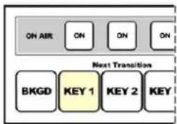
flowchart
graph TD
    A["ON AIR"] --> B["ON"]
    B --> C["ON"]
    C --> D["ON"]
    E["BKGD"] --> F["KEY 1"]
    F --> G["KEY 2"]
    G --> H["KEY"]
    style E fill:#FFD700,stroke:#333
    style F fill:#FFD700,stroke:#333
    style G fill:#FFD700,stroke:#333
    style H fill:#FFD700,stroke:#333
Control panel next transition buttons before transition.
natural_image
Soccer goalkeeper in action at the goal with a goal net nearby, crowd visible in background (no text or symbols)Program output before transition.
natural_image
Soccer player in action shot with goal net, crowd background (no visible text or symbols)Program output after transition
Example 2:
In this example, key 1 is currently on air, indicated by the illuminated ON button. The next transition has Key 1 selected, therefore the next transition will change the state of key 1 and turn it OFF so that it is not visible on the program output.
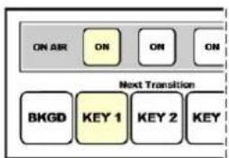
Control panel next transition buttons before transition.
natural_image
Soccer goalkeeper in action at the goal with a 'LIVE' banner in the corner (no readable text on player or ball)Program output before transition.
natural_image
Soccer goalkeeper standing at the goal with a soccer ball in the background (no visible text or symbols)Program output after transition.
Example 3:
In this example, key 1 and key 2 are on-air, indicated by the illuminated ON buttons. The next transition has the background selected, indicated by the illuminated BKGD button, therefore the next transition will only transition the background leaving both key 1 and key 2 on-air.
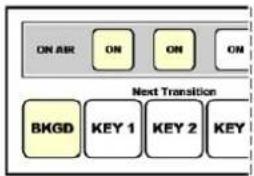
flowchart
graph TD
    A["ON AIR"] --> B["ON"]
    B --> C["ON"]
    C --> D["ON"]
    E["BkgD"] --> F["KEY 1"]
    F --> G["KEY 2"]
    G --> H["KEY"]
Control panel next transition buttons before transition.
Program output before transition. Program output after transition.
natural_image
Two soccer players in action on a grass field, one in green and one in red, with 'LIVE' and 'BMD TV' labels (no readable text or symbols)Example 4:
In this example, key 1 and key 2 are on-air. The next transition has the background and key 2 selected, therefore the next transition will transition the background and change the state of key 2 turning it OFF so that it is not visible on the program output.
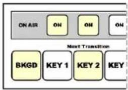
Control panel next transition buttons before transition.
Program output before transition. Program output after transition.
natural_image
Two soccer players in action on a grass field, one in green and one in red, kicking up the ball (no visible text or symbols)There are multiple ways to transition a key to the program output. The key can be cut on or off, it can be mixed on or off, or it can be mixed along with a background transition. Upstream keys are transitioned to the program output using the next transition block. Downstream keyers can be transitioned using their own transition buttons or by using the DSK TIE button to link the transition with the main transition control block.
Performing Downstream Keyer Transitions
The downstream keyers have their own transition buttons and transition rate windows. Once a downstream keyer is configured it can be easily taken on and off the program output using one of the following three methods:
1 Press the DSK CUT button to immediately turn on or turn off the downstream key on the program output.
2 Use the DSK AUTO button to gradually transition the downstream key on or off the program output at the rate displayed in the DSK rate window.
3 Use the DSK TIE button to link the downstream key with the main transition control block. Once linked the DSK will be mixed on or off along with any transition type selected in the main transition control block at the rate specified by the transition control block.
Pressing the DSK TIE button shows the downstream keyer on the preview output.
It is not possible to preview a downstream keyer transition when linked with the main transition block. If the DSK TIE button is on when you switch to preview transition mode the tie functionality will be ignored until the preview transition mode is turned off.
DSK parameters
| Clip | The clip level adjusts the threshold at which the key cuts its hole. Decreasing the clip level reveals more of the background. If the background video is completely black then the clip value is too high. |
| Gain | The gain adjustment electronically modifies the angle between on and off thereby softening the edges of the key. Adjust the gain value until the edge softness is desirable but the background video luminance (brightness) is not affected. |
| Rate | The mix rate at which the downstream keyer transitions on or off. |
| Inverse | Inverts the key signal. |
| Pre-Mult | Identifies the key signal as a pre-multiplied key. |
Using Adobe Photoshop with ATEM
Installing the ATEM software on your computer also installs a Photoshop plug-in that lets you download Photoshop graphics direct to the ATEM media pool.
This means you can accept graphics from designers in the application that 100% of the world's designers use, Adobe Photoshop! You can even use the layers in a Photoshop image to keep variations of graphics, such as different titles in a graphic, then select the layers in Photoshop you want and then simply download them at the press of a button. When downloading the layers are automatically flattened in real time before download. This happens in the background and your document in Photoshop is unchanged by the export.
The ATEM export plug-in requires Adobe Photoshop CS5 or later. Install or reinstall the ATEM software after Photoshop is installed, to ensure the ATEM export plug-in is installed.
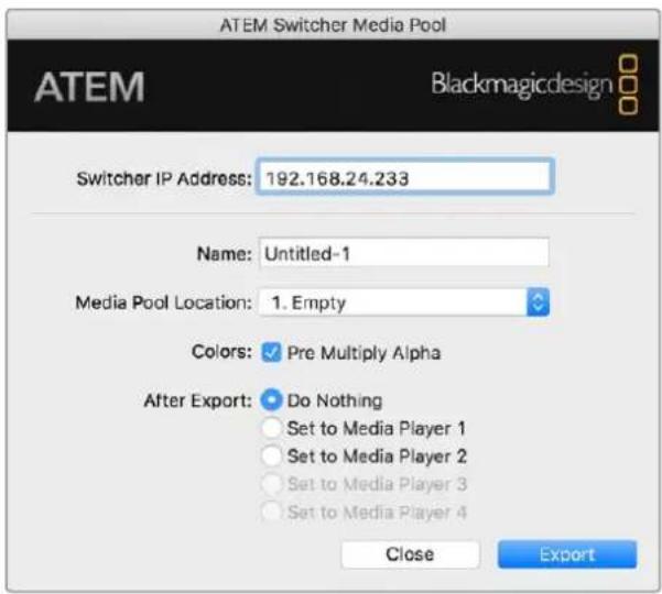
ATEM export plug-in
Setting up Plug-in Switcher Location
The first time the Photoshop export plug-in is run, it will ask you to select your switcher location. This is the IP address of the switcher so the plug-in can find the switcher to communicate with. By default, the IP is set to 192.168.10.240, which is what the switcher IP address is originally set to when first sold. If you want to export several versions of the same Photoshop file, you can use the export plug-in window to name each exported file and also choose whether to set the files to a Media Player after export.
Preparing Graphics for Download
For best results, you will want to use a Photoshop document resolution that matches the video standard you're using with your ATEM switcher. For 8K you should use documents that are 7680 x 4320 pixels in resolution. For Ultra HD you should use documents that are 3840 x 2160 pixels in resolution. For 1080 HD you should use 1920 x 1080 pixels in resolution. For 720p HD formats you should use 1280 x 720 pixels. For PAL standard definition you should use 720 x 576 and for NTSC you should use 720 x 486 pixels resolution documents.
When working with Photoshop documents for ATEM, you should not put any content on the background layer, but add all content to the layers above. The background layer should always be plain full frame black and you should use a pre-multiplied key setting in the ATEM keyers for keying graphics from Photoshop.
To help you get started, we've included a guide and some graphic template files in the Example Graphics folder which was installed on your computer along with the ATEM Switchers software.
To download the graphic to the ATEM media pool, simply select the export menu in Photoshop and then select ATEM Switcher Media Pool to export. A window will appear asking you to choose which position in the media pool you want to download to. The list includes all the file names of graphics currently loaded in the media pool. Select which position you would like to download to and then select export.
If you're in a hurry to get your graphics on air, then you can select to automatically copy this graphic to either media player 1 or media player 2 after download. This lets you get images to air fast! If you don't want to interfere with the media player graphic sources, simply select not to copy the media players to this graphic.
Pre Multiply Alpha should almost always be enabled and requires that you also switch on the Pre Multiplied Key setting in ATEM Software Control or on the optional ATEM Broadcast Panel. Premultiplying mixes the graphic color with its alpha channel when exporting to ensure your graphic has smooth edges which blend in to the video.
Using Auxiliary Outputs
Auxiliary outputs are extra SDI outputs that can have various inputs and internal sources routed to them. They are very similar to router outputs and all video inputs, color generators, media players, program, preview and even color bars can be output. ATEM Production Studio 4K has 1 auxiliary output and most other switcher models have multiple auxiliary outputs. ATEM Constellation 8K has an abundance of general purpose outputs instead of auxiliary outputs, which means any source can be routed to them.
If you need an extra program output, then aux outputs are ideal, or if you need a clean feed before one or both of the down stream keyers, then you can even select these to the aux outputs. This will give you a program feed without a logo or bug, so you can capture this as a broadcast master for later post production or transmission.
Aux outputs are extremely powerful and can be routed on the software control panel, as well as the hardware based broadcast panel. The aux output menus are available in the menu bar at the top of the software control panel regardless of the window currently selected so they are always available. The 'outputs' menu in the software control panel for ATEM Constellation 8K has flexible routing options for all 24 outputs in HD and Ultra HD modes and all six 8K outputs. For more information, see the 'Routing Auxiliary Outputs' section.
The switcher will always perform a clean switch when an auxiliary output changes sources so this means you can use the switcher to cut between sources on the auxiliary output cleanly and without glitches.
The ATEM Production Studio 4K models feature illuminated buttons on the front panel together with a built in LCD screen. Assigning an aux output is as easy as selecting an aux button from the right hand row and pressing one of the source buttons on the left. The LCD screen will then display that output. This feature not only gives you a fast visual indicator of your connections, but also serves as a powerful auxiliary switcher!

Auxiliary Outputs Control Menus on Mac

Auxiliary Outputs Control Menus on Windows
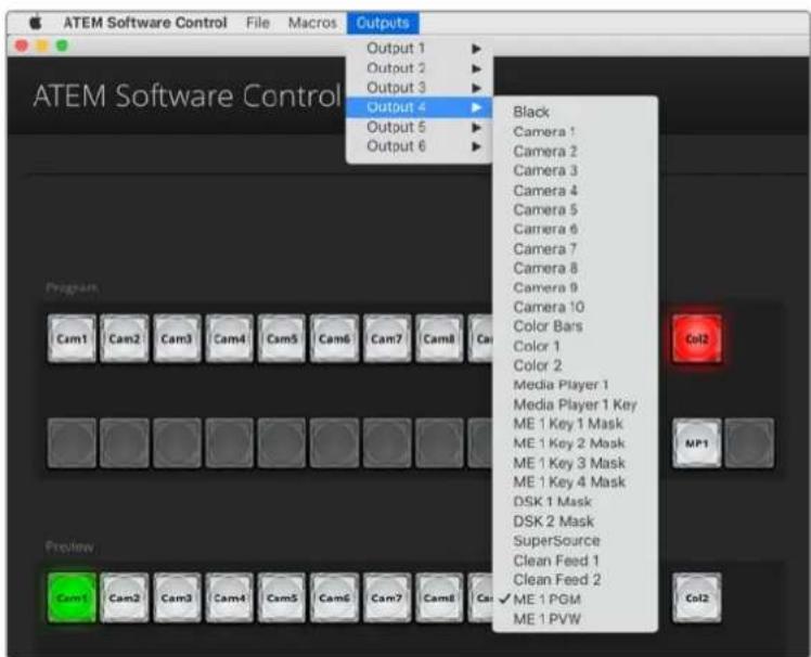
ATEM Software Control menus for routing outputs for ATEM Constellation 8K.
Routing Auxiliary Outputs
On the ATEM software control each aux output has a menu for selecting the source to output on the aux video output. Select the menu and then scroll the list for the source you want to output. When selected, the output on the selected aux will change immediately. You can see the current source with a tick in the menu item.
On the ATEM broadcast panel the aux outputs are set from the aux menu in the system control. Once the desired aux output is selected, you use the select bus to route the source to the aux output. Because the broadcast panel uses the select bus, it's very fast to control aux outputs from the broadcast panel.
Auxiliary outputs are assignable on the ATEM 2 M/E Broadcast Panel using the Destination bus. Once the desired Aux is selected in the Destination bus, you can use the Select bus to assign an input to it.
Whatever video and audio is output on Aux 1 is also output on the USB 3.0 port.
There are a range of sources available and these include:
Black
Black source generated internally in the switcher.
Inputs
You will see the video inputs of the switcher listed and these will be listed as the current labels you have set in the settings window of the switcher.
Color Bars
Color bar source generated internally in the switcher.
Media Player 1
This is the fill output of media player 1 and is derived from the still or clips RGB content.
Media Player 1 Key
This is the key output from media player 1 and is derived from the still or clips alpha content. After selecting the aux you want to route to on the ATEM 2 M/E Broadcast Panel, make the selection on the select bus. On the ATEM 1 M/E Broadcast Panel, after selecting the aux you want to route to, hold shift and make the selection on the select bus.
Media Player 2
This is the fill output of media player 2 and is derived from the still or clips RGB content.
Media Player 2 Key
This is the key output from media player 2 and is derived from the still or clips alpha content. After selecting the aux you want to route to on the ATEM 2 M/E Broadcast Panel, make the selection on the select bus. On the ATEM 1 M/E Broadcast Panel, after selecting the aux you want to route to, hold shift and make the selection on the select bus.
Program
This is the switcher program out and is the same as the main program SDI output on the switcher. After selecting the aux you want to route to on the ATEM 2 M/E Broadcast Panel, hold the two shift buttons and then make the selection on the select bus. On the ATEM 1 M/E Broadcast Panel, after selecting the aux you want to route to, hold the shift button and cut/fill button and then make the selection on the select bus.
Preview
The preview output shows the source selected on the preview bus, which is also shown in the preview window in the multi view. After selecting the aux you want to route to on the ATEM 2 M/E Broadcast Panel, hold the two shift buttons and then make the selection on the select bus. On the ATEM 1 M/E Broadcast Panel, after selecting the aux you want to route to, hold the shift button and cut/fill button and then make the selection on the select bus.
Clean Feed 1
This is identical to the program output, however does not include any of the downstream keyer contents. It's useful when you want to record a master output without logos or bugs on the downstream keyers. After selecting the aux you want to route to on the ATEM 2 M/E Broadcast Panel, hold the two shift buttons and then make the selection on the select bus. On the ATEM 1 M/E Broadcast Panel, after selecting the aux you want to route to, hold the shift button and cut/fill button and then make the selection on the select bus.
Clean Feed 2
This is the same as above, however this output is taken from between the two down stream keyers so so includes down stream keyer 1, but not down stream keyer 2's output. After selecting the aux you want to route to on the ATEM 2 M/E Broadcast Panel, hold the two shift buttons and then make the selection on the select bus. On the ATEM 1 M/E Broadcast Panel, after selecting the aux you want to route to, hold the shift button and cut/fill button and then make the selection on the select bus.
Routing clean feeds to aux outputs allows ultimate flexibility in the use of your program video. From the aux outputs you can record a version of your program free from any local broadcast branding you might have applied from the down stream keyer. This 'clean' version could then be used for an international broadcast. This is a very powerful feature!
Using SuperSource (Picture in Picture)
ATEM 2 M/E switcher models include a feature referred to as SuperSource (Picture in Picture or PIP) that will allow you to arrange multiple sources on the monitor at one time.
ATEM Constellation 8K has two SuperSources in HD and Ultra HD and one in 8K. This is useful as there are occasions when you need to see more than one source on the monitor. It's great to know that the SuperSource processor appears on your ATEM Switcher as a single video input. You can even select the Mix Effects 2 program or preview output as a box source for your selected layout.
Setting up SuperSource
You can set up SuperSource using either the joystick on your ATEM panel or using the ATEM Software Control Panel (GUI).
Viewing SuperSource
To set up SuperSource, first you need to be able to view it on your monitor. Do this by either assigning SuperSource from the Settings tab in the GUI to a multi view window or by placing SuperSource on the preview output of your monitor if using an ATEM panel.
Positioning Sources
Using the GUI you can open the SuperSource palette and choose from one of the four preset layouts. Click the one that is closest to the look you want, this will automatically arrange the boxes into the preset positions indicated on the GUI. Make sure the box is enabled. You can then change the position and size via the X Position, Y Position and Size fields. Ticking the Enable Crop check box allows you to crop the image. The crop parameters are Top, Bottom, Left and Right. You may then wish to alter the parameters of boxes 2 to 4 by doing similar steps. If you make a mistake, click on the cog symbol on the RHS of the Box Control tab and you can easily reset the parameters.
If you are using a Control Panel, in the Home Menu press the button marked SuperSource and then choose Preset Menu. In this menu you can choose any of the four presets. Go back and then select the individual box that you want to manipulate. Moving an image is fun and easy via the panel's joystick. You can select the box to be moved in one of the following 3 ways.
- In the SuperSource menu, push the button marked with a box number, in this case box 1 and the joystick will be auto assigned to the box that you have selected. Easily select more than one box at a time by holding down 2 or more of these buttons!
- Use the buttons next to the joystick itself. As an example, a single tap will select box 1 on the lower right or a rapid double tap will select box 3.
- Finally, push a dedicated destination button on the 2 M/E panel or select button on the 1 M/E panel.
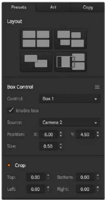
SuperSource settings
When using the Control Panel, you can use the Enable button to switch a particular box on or off. Choose the source you wish to place in the box from the Source Select bus. Press the dedicated Destination button followed by the desired source. Then choose the Position and the Size either via the window or the joystick. If you decide that you want to use Crop, select the Crop Menu button and select the crop button. Each box can be cropped individually and the parameters are Top, Bottom, Left and Right. If you become confused then crop can be reset via the crop reset button.
Background and Foreground Art
To use background art, clicking on the button marked Art on the GUI or the ATEM Panel will reveal the Art settings. To use art as a background source, select the button marked Background. Then choose your Art Fill Source via the GUI drop down box, or on the ATEM panel by the Source Select bus. Assign the source and your choice will be placed behind the on screen boxes.
On the panel, in the SuperSource menu press the button marked art and then press the button marked Background. Select the source for the background via the Select bus on the 1 M/E panel or the dedicated Destination bus on the 2 M/E panel. This will result in the selected video source being placed behind the enabled boxes.
On the GUI if you wish to make the art foreground, then click on the radio button marked Foreground and choose whether your graphic is Pre Multiplied or not. If it is Pre Multiplied then tick the check box, assign the Art Fill Source and the Art Key Source. This will now allow the art to be placed over the enabled box or boxes. If your art is not pre multiplied then you can use the clip and gain controls as discussed in the Keying section of this manual to achieve the desired result.
On the panel if you wish to make the art foreground, then click on the button marked Foreground and choose whether your graphic is Pre Multiplied or not. If it is Pre Multiplied then press the button marked with this label and assign the Art Fill Source and the Art Key Source.
This will now allow the art to be placed over the enabled box or boxes. If your art is not Pre Multiplied then you can use the clip and gain controls as discussed in the Keying section of this manual to achieve the desired result. You may also need to invert the key.
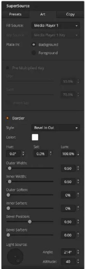
Art Foreground controls
Adjusting Borders
Borders are created the same way for both the GUI and the ATEM panel. Simply click on the button marked Borders. This will allow access to all the border parameters as previously discussed in this manual under "Adding DVE borders".
Please note that if you are using the Art in Foreground mode then the borders are not available as they would not be visible and that any or all border settings are applied to all boxes. Also note that ATEM Constellation 8K presents SuperSource without borders in 8K.
Copying Settings
To perform the Copy function using the GUI, simply click on the Copy button and the Copy Box Settings dialogue will appear. You can quickly & easily copy the settings of the currently selected box to any of the other boxes, making an exact clone in just one click! The copied boxes will appear directly behind the master box and will also share the same source as the master.
If you are using an ATEM panel, select any box via the SuperSource main menu and then the button marked Copy To. In the window, the currently marked box will then be copied to any of the other boxes as selected. As with the GUI, the copied boxes will appear directly behind the master box and will also share the same source as the master.
Putting SuperSource On Air
The entire SuperSource processor appears on your ATEM Switcher as a video input. Simply select the SuperSource button on the GUI or the ATEM panel to use the composite you have just made!
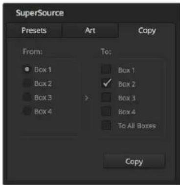
Copying the settings of Box 1 to Box 2
Using Macros
What is a Macro?
A macro is an easy way to automate a sequence of switcher actions so you can repeat the sequence at the press, or click, of a button. For example, you can record a sequence of transitions between several video sources, including key effects, audio mixer adjustments, camera control settings and more. Record all your actions to a macro button, then when you press that button all your recorded actions will be instantly performed. Macros are recorded using the macros window in ATEM Software Control, an ATEM Broadcast Panel, or a combination of the two and are stored inside your ATEM switcher. Macros are common to all control panels, they can be triggered using any control panel you like.
The Macros Window in ATEM Software Control
To open the macros window in ATEM Software Control, click on macros in the title bar, or you can also press shift/command/M for Mac, or shift/control/M for Windows. The macros window is a floating window you can move freely about your desktop. This is so you can always access the window when moving between the switcher, media, audio and camera pages. While recording a macro, you can even reduce the size of the window by clicking on the minimize icon at the top right corner.
Macros can be recorded to any of the 100 macro slots. Up to 20 macro slots are visible on each page. Move forwards and backwards through pages by clicking on the arrows on the bottom sides of the window. Clicking on the create and run buttons lets you swap between the create and run pages so you can record your macros and then run them during your live production.
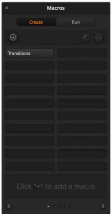
The macros window in ATEM Software Control lets you record and run macros so you can easily repeat a sequence of complex switcher actions at the click of a button.
Recording Macros
Macros need to be recorded comprehensively, in clearly defined sequences from start to finish without error. This is because your macro will record every setting, press of a button and switcher action you perform. When you run a macro, all the switcher actions you recorded in that macro will be repeated precisely.
It's worth highlighting that a macro will only record the settings you change. For example, if you want a 3:00 second transition and your switcher's transition rate is already set to 3:00 seconds, you'll need to change the duration, then set it back to 3:00 seconds to record the setting. If not, your desired transition rate will not be recorded and when the macro is run it will simply use the transition rate your switcher was last set to. So you can see why precision is important!
If settings are changed while recording a macro and you want them restored to a particular state, simply restore those settings while recording the final steps of the macro. You can even record macros to restore settings for various projects. You have lots of choices. The important thing to remember when recording a macro is that you change all the settings you need to so you can create the specific effects you want.
Recording a Macro using ATEM Software Control
In the example below, we're going to create a macro that will set your ATEM switcher to perform a 3 second mix transition from color bars to color 1, pause for 2 seconds, then perform a 3 second mix transition to black. Try building this macro on your ATEM switcher so you can learn the steps in creating macros.
1 Launch ATEM Software Control and open the macros window.
2 Click on the create button in the macros window to select the create page.
3 Click on a macro slot you want to record your macro to. In this example, click on macro slot 1. An orange border will appear around the slot you have selected.
4 Click on the create macro button ('plus' icon) to open the create macro popup window.
If you want to, you can enter the name of your macro and type a description. This lets you easily keep track of your macros and quickly see what each macro does. When you click on a macro, your notes will appear in the status window.
5 Click the 'record' button.
The popup window will close and a red border will appear around your ATEM Software Control panel indicating your macro is now recording. Notice the red 'add pause' button at the top of the border.
Now that your macro is recording, you can start performing your switcher actions.
6 Click on the bars button in the program panel on the switcher page. This sets bars to your switcher's program output.
7 Select color 1 on the preview panel.
8 Open the transitions palette and set it to mix.
If mix is already selected, make sure your macro records the setting by selecting a different transition type, for example the wipe transition, then clicking on mix again.
9 Now change the transition Rate to 3:00. This sets the mix transition duration to 3 seconds.
10 Click on the auto button in the transition style panel. Your switcher will perform a mix transition from color bars to color 1.
11 To set the switcher to wait for 2 seconds before applying another transition, click on the add pause button at the top of the red border. The 'insert pause' window will open. Set the pause to 5 seconds and 00 frames and click 'confirm'.
Why set a 5 second pause when you only want a 2 second pause? That's because when the mix transition occurs, it takes 3 seconds to complete. So if you want to add a pause, you need to consider the transition duration, plus the pause you want to happen before the next transition occurs.
In this example, it takes 3 seconds for the transition to complete, then 2 seconds for your 2 second pause, so you should enter a pause of 5 seconds. Another way is to add two separate pauses, one for the duration of the transition and then another for the pause you want. It's up to you.
12 Now select black on the preview panel and click the auto button in the transition style panel. Your ATEM switcher will perform a mix transition to black.
13 Click the record icon in the macros window to stop recording your macro.
The macro you just recorded will now appear as a button in your selected macro slot. To preview your macro, click the run button in the macros window to enter the run page. Select recall and run, which sets the macros window to run a macro as soon as you click on a macro button. Now click on your new macro button, named 'Transitions'.
14 If you want your macro to instantly run as soon as you select it, click on the 'recall and run' button. By enabling this feature you can load and play your macros with only one click of a button.
Congratulations! If your macro was successful, you should see your ATEM switcher perform a mix from color bars to color 1 using a 3 second transition, pause for 2 seconds, then perform another 3 second mix transition to black, all by clicking one button in the macros window! Your ATEM switcher will also display an orange border around your software control panel to indicate a macro is playing.
If your macro doesn't perform the way you expect it to, simply rerecord the macro you just created following the previous steps.
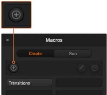
To start recording a macro, select a macro slot, then click on the create macro button. Type in your notes and click 'record'.
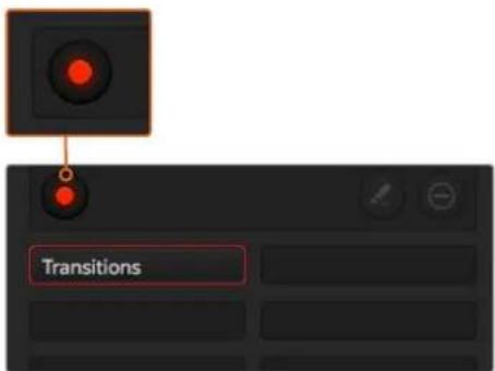
While recording, the create macro button will change to a 'record' button. When you have completed your switcher actions, click on the 'record' button to stop recording.
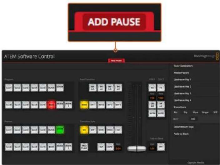
ATEM Software Control displays a red border to indicate when you are recording a macro. The 'add pause' button located at the top of the red border lets you enter durations for pauses between switcher actions.
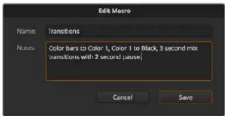
Enter a name for your macro and a description so you can keep track of the switcher actions recorded in the macro.
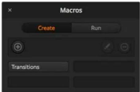
The image above shows how a macro button appears in the macros window after it has been recorded. To run a macro, click on the 'run' button to enter the run page. Now you can load and/or run the macro by clicking on the macro button.
Building Large Macros
Macros can even include triggering other macros as part of recording a macro. This lets you easily build larger macros from multiple smaller macros, i.e., recording macros with limited actions, then compiling them into a large macro. This is because if there are any mistakes while recording a large macro in one complete sequence, you'll need to go back to the start of your sequence and rerecord it. It's a lot easier to work with segments containing a small number of actions.
By recording a large macro using small macros, you can also edit your large macro by rerecording only the small macros you want to change, then compiling your small macros back into your large macro.
To compile small macros into a large macro:
1 Start recording a new macro, then while the macro is recording, click on the 'run' button to enter the run page.
2 Select 'recall and run' to automatically run macros at the push or click of a button, or deselect to load a macro and play it manually.
3 Run your sequence of small macros, with pauses between each one to cover the duration of each small macro, until you've completed the large macro.
4 Stop recording. You now have a complex, powerful large macro built from small macros you can easily change later if you need to.
There is no limit to the amount of actions you can perform. You can easily build complex transitions, create unique repeatable effects using keyers, or set up frequently used Blackmagic Studio Camera settings, graphic overlays and DVEs so you don't have to reconstruct them every time you start a new program. Macros are fun and will save you a lot of time!
Macros Window Create Page
Create macro button:
Click this button to open the create macro popup window. From here you can name a new macro to be recorded, write a description of your macro in the notes section and click record to start recording your macro.
Arrow buttons and page Icons:
To access or record more than 20 macros, simply click on the right arrow at the bottom corner of the macros window to open a new page of macros. To move to the previous page of macros, click on the left arrow. You can see which page of macros you are viewing by observing the page icons between the arrows.
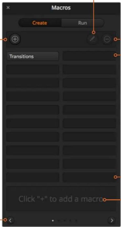
Edit macro button:
First select the macro you want to edit, then click on the edit macro button to edit the name and description of the macro.
Delete macro button:
Select the macro you want to delete, then click on the delete macro button to delete the selected macro.
Macro buttons:
After recording a macro to a selected macro slot, your macro will appear as a macro button. 20 macro buttons can be displayed on one page. If a macro is unnamed when recording, the number of the selected macro slot will be used.
Status window:
This window provides helpful prompts and status messages to help you get started recording and running your macros. When a macro is selected, it also displays any notes you have included.
Macros Window Run Page
Recall and Run:
Selecting the Recall and Run feature lets you instantly run a macro by clicking a macro button. Deselecting the Recall and Run feature lets you load a macro by clicking on your macro button. Run the macro by clicking the play button.
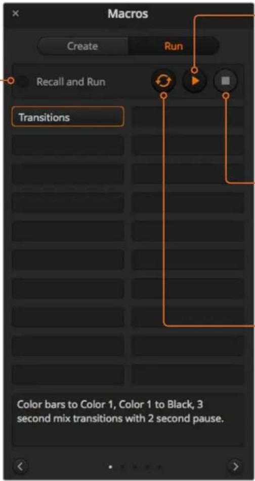
Play:
When Recall and Run is deselected and you have loaded a macro by clicking on a macro button, click the play icon to start playing the macro.
Stop:
Clicking the stop button will stop the playback of a macro, but will complete the current action first. For example, if you press stop half way into a transition, the switcher will finish the transition and then stop.
Loop:
When the loop button is selected and you run a macro, your macro will run continuously until you click the stop button. When loop is deselected, your macro will run until it is completed.
Recording Macros using an ATEM 1 M/E Broadcast Panel
You can record and run macros using an ATEM 1 M/E Broadcast Panel independently of ATEM Software Control. All actions on the ATEM Software Control switcher page can be performed using your hardware panel. If you need to mix audio, arrange graphics in the media pool, or adjust camera settings, simply access those settings using ATEM Software Control.
The buttons used to record and run macros on the ATEM 1 M/E Broadcast Panel are located in the system control soft buttons. The names of your macro buttons are displayed in short form in the source names display and you can view them by pressing the show names soft button. Macro names longer than 4 characters are shown in their entirety in the system control LED display.
Recording a macro is easy. After pressing the 'macro' soft button to enter the macro menu, select a macro slot by pressing any of the 10 macro buttons in the select bus. Shift select if you want a macro slot up to 20. To select macro slots above 20 use the numeric keypad. Simply type in a number between 1 to 100 and press the cam button to confirm your selection. Another method is by turning the knob under the system control LED display. The same methods are used to recall and run macros during your live production.
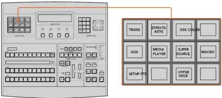
The system control soft buttons on your ATEM 1 M/E Broadcast Panel lets you record and run macros from the panel itself. Press the 'macro' button in the system control 'home' menu to enter the macros soft button menu.
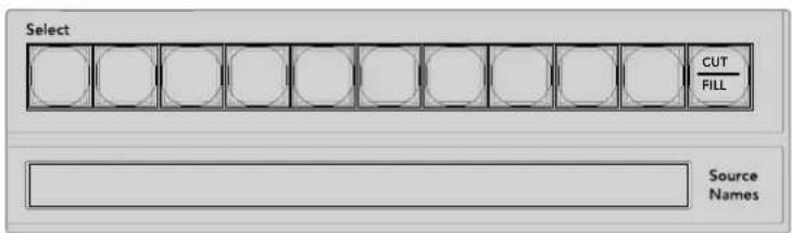
Macro buttons for the first 20 macro slots are located in the select bus. Shift select to select a macro above slot 10, or use the numeric keypad. Recorded macros up to 20 will display their respective names in short form on the source names display.
Follow the steps below to create the same 'Transitions' macro demonstrated earlier using ATEM Software Control. This time you'll create a macro in macro slot 2.
1 Press the macro soft button in the system control 'home' menu.
2 Press macro slot button 2 located above the program bus, or by using the numeric keypad.
3 Press the record soft button. The button will begin flashing indicating you are now recording a macro. You can also see the red border displayed around the ATEM Software Control panel.
4 Shift select bars on the Program bus. The button will flash indicating it's a shifted source.
5 Shift select col1 on the preview bus. If you wish, you can easily map buttons such as bars, black and color generators to any of the first 10 buttons of the program and preview bus for easier access. See the 'button mapping' section of this manual for instructions.
6 Press the DVE/wipe button in transition control and then press dip/mix to ensure the macro records the mix transition selection.
7 Press the orange home button to exit the macro soft buttons in order to access the transition settings. Don't worry, the macro will still be recording while a different system control menu is selected.
8 Press the trans soft button to enter the transition settings. You'll see the transition settings displayed on the system control LED display. Turn the knob under the mix setting to set a 3:00 second transition rate. Press the system control home button again to exit the transition settings and press macro to return to the macro soft buttons. The record button is flashing so you can see your macro is still recording.
9 Press the auto button in transition control to perform the transition from color bars to color 1.
10 To set the macro to wait for 2 seconds before applying the next transition, press and hold the add pause soft button. Notice the time durations shown in the source names display. Select 2:00, 2:00 again and 1:00 from the macro buttons above the durations. The durations are accumulative so you can build various pause times. *Inserted Pause* will momentarily display on the system control LED display to confirm your pause.
11 Now shift select blk on the preview bus and press the auto button. Your ATEM switcher will perform a mix transition to black.
12 Press the record soft button to stop recording your macro.
You've just recorded a macro using an ATEM 1 M/E Broadcast Panel. The macro will appear as a macro button named '2' because it is located in macro slot 2. The number of characters are limited on control panels, but you can easily name your macro and add notes by clicking on the 'edit macro' button in ATEM Software Control. For this reason, it's probably better to record macros using ATEM Software Control, however you can record a macro from any control panel you like.
To run your macro, press the 'play' soft button. If your macro was successful, you should see your ATEM switcher mix from color bars to color 1 using a 3 second mix transition, pause for 2 seconds, then perform another 3 second mix transition to black, all by pressing one button on your ATEM 1 M/E Broadcast Panel.
To edit the name of the macro you just recorded, click on the edit macro button on the create page of the macros window in ATEM Software Control. You can also add notes to describe the macro.
It's worth frequently testing your macros using different switcher settings to make sure the macro performs all the specific functions you intended, doesn't miss any instructions or produce something unexpected.
If you want to record over a previously recorded macro, or if you made a mistake and want to start recording a macro again, shift select the record button. This is a safety measure to prevent accidentally recording over a macro.
For information on the macro delete, show names, stop and loop buttons, refer to the System Control Macros Menu section.
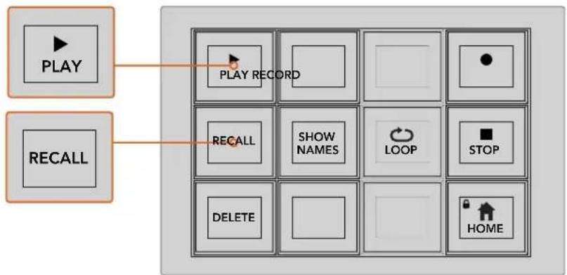
flowchart
graph TD
    A["PLAY"] --> B["PLAY RECORD"]
    C["RECALL"] --> D["RECALL"]
    C --> E["SHOW NAMES"]
    C --> F["LOOP"]
    C --> G["STOP"]
    C --> H["DELETE"]
    C --> I["HOME"]
To load a macro so it is cued and ready to run, make sure the recall soft button is selected. Select the macro you want to run by pressing the desired macro button, or using the numeric keypad. Now you can run your macro at any time by pressing the play soft button. When 'recall and run' is selected, your macro will automatically run as soon as you select it.
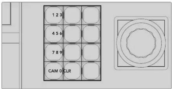
Use the joystick control keypad to select up to 100 macros to record and run. Simply type in the desired macro number and press 'cam' to select your macro to run, or macro slot to record.
Recording Macros using an ATEM 2 M/E Broadcast Panel
You can record and run macros using your ATEM 2 M/E Broadcast Panel independently of ATEM Software Control. All actions on the ATEM Software Control switcher page can be performed using your hardware panel. If you need to mix audio, arrange graphics in the media pool, or adjust camera settings, simply access those settings using ATEM Software Control.
Dedicated macros buttons are used to record and run macros on the ATEM 2 M/E Broadcast Panel, or you can use the system control M/E 1 or M/E 2 soft menu buttons, which also provide additional macros functions. The names of your macro buttons are displayed in the source names display by pressing the show names soft button. Macro names longer than can be shown in the source names display are shown in their entirety in the system control M/E 1 or M/E 2 LED displays.
The M/E 1 and M/E 2 system control blocks are used depending on how many ATEM switchers are connected to your panel. For example, if you have two ATEM switchers connected, you can access up to 100 macros for each M/E block. The macros menus for each block are exactly the same.
Recording a macro is easy. Select a macro slot by pressing any of the 20 macro buttons in the source select bus. Shift select if you want a macro slot up to 40. To select macro slots above 40 use the numeric keypad under the joystick control block. Simply type in a number between 1 to 100 and press the cam button to confirm your selection. Another method is by turning the knob under the system control LED display. The same methods are used to recall and run macros during your live production.
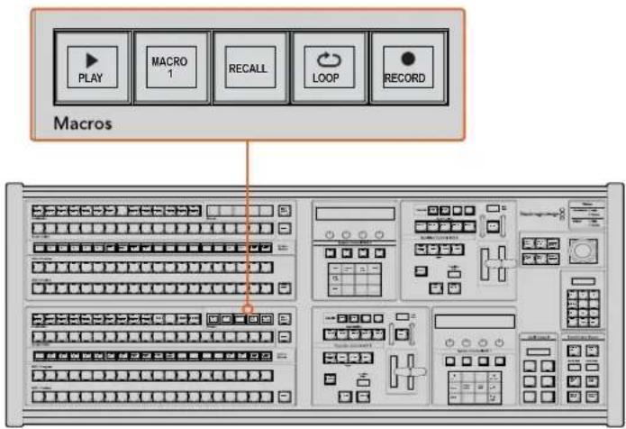
The dedicated macro buttons on your ATEM 2 M/E Broadcast Panel lets you record and run macros from the panel itself. Turning on the loop feature will run a macro on a continuous loop until you press the stop button, or turn loop off.
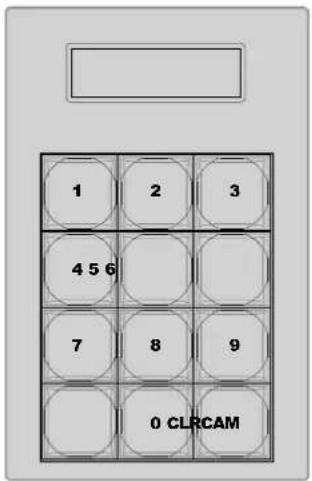
Use the keypad under the joystick control to select up to 100 macros to record and run. Simply type in the desired macro number and press 'cam' to select your macro to run, or macro slot to record.
Follow the steps below to create the same 'Transitions' macro demonstrated earlier using ATEM Software Control, except this time you'll record to macro slot 2.
1 Press macro slot button 2 in the source select bus located above the program bus, or by using the numeric keypad.
2 Press the record button in the macros block. The record button will begin flashing indicating you are now recording a macro. You can also see the red border displayed around the ATEM Software Control panel.
3 Select bars on the Program bus. Depending on the ATEM switcher you're using, you may need to shift select bars on your broadcast panel. The button will flash if it's a shifted source.
4 Select col1 on the preview bus.
If you wish, you can easily map buttons such as bars, black and color generators to any of the first 20 buttons of the program and preview bus. See the 'button mapping' section of this manual for instructions.
5 Press the DVE/wipe button in the active M/E transition control and then press dip/mix to ensure the macro records the mix transition selection.
6 Press the orange 'home' soft button in the system control macros menu. Now you can access the transition settings. Don't worry, the macro will still be recording while a different menu layout is selected.
7 Press the trans soft button to enter the transition settings. You'll see the transition settings displayed on the active system control LED display. Turn the knob under the mix setting to set a 3:00 second transition rate. Press the home button again to exit the transition settings and press macro to return to the macro soft buttons. The record button is flashing so you can see your macro is still recording.
8 Press the auto button in transition control to perform the transition from color bars to color 1.
9 To set the macro to wait for 2 seconds before applying the next transition, press and hold the add pause soft button in the macros block. Notice the time durations shown in the source names display. Select 2:00, 2:00 again and 1:00 from the macro buttons above the durations. The durations are accumulative so you can build various pause times. *Inserted Pause* will momentarily display on the active system control LED display to confirm your pause.
10 Now select blk on the preview bus and press the auto button. Your ATEM switcher will perform a mix transition to black.
11 Press the record soft button in the macros block to stop recording your macro.
You've just recorded a macro using an ATEM 2 M/E Broadcast Panel. The macro will appear as a macro button named '2' because it is located in macro slot 2. The number of characters are limited on control panels, but you can easily name your macro and add notes by clicking on the 'edit macro' button in ATEM Software Control. For this reason, it's probably better to record macros using ATEM Software Control, however you can record a macro from any control panel you like.
To run your macro, press the play soft button in the macros block. If your macro was successful, you should see your ATEM switcher mix from color bars to color 1 using a 3 second mix transition, pause for 2 seconds, then perform another 3 second mix transition to black, all by pressing one button on your ATEM 2 M/E Broadcast Panel.
To edit the name of the macro you just recorded, click on the edit macro button on the create page of the macros window in ATEM Software Control. You can also add notes to describe the macro.
It's worth frequently testing your macros using different switcher settings to make sure the macro performs all the specific functions you intended, doesn't miss any instructions or produce something unexpected.
If you want to record over a previously recorded macro, or if you made a mistake and want to start recording a macro again, shift select the record button. This is a safety measure to prevent accidentally recording over a macro.
For information on the macro delete, show names, stop and loop buttons, refer to the System Control Macros Menu section.
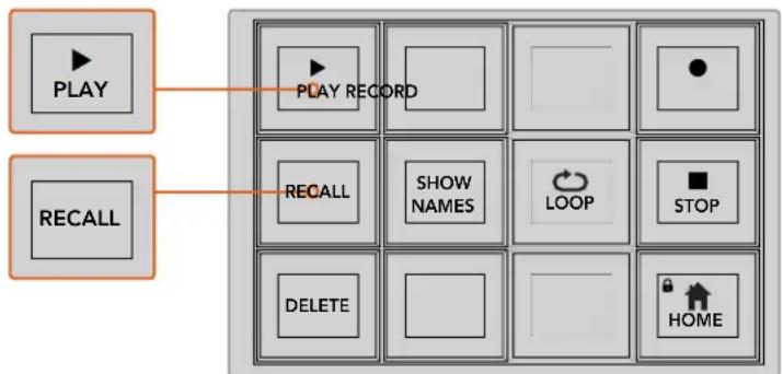
flowchart
graph TD
    A["PLAY"] --> B["PLAY RECORD"]
    C["RECALL"] --> D["RECALL"]
    C --> E["SHOW NAMES"]
    C --> F["LOOP"]
    C --> G["STOP"]
    C --> H["DELETE"]
    C --> I["HOME"]
To load a macro so it's cued and ready to run, make sure the recall button is selected. Select the macro you want to run by pressing the desired macro button, or using the numeric keypad. Now you can run your macro at any time by pressing the play button. When recall and run is selected, your macro will automatically run as soon as you select it.
System Control Macros Menu
The system control menu soft buttons perform exactly the same macro functions for both ATEM 1 M/E and 2 M/E Broadcast panels. These buttons let you record, run and delete macros, plus select macro playback features such as recall/recall and run and loop. Press the 'macro' button on the system control 'home' menu to access the macro soft buttons.
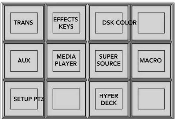
The system control macros menu is accessed by pressing the macro soft button on the system control 'home' menu.
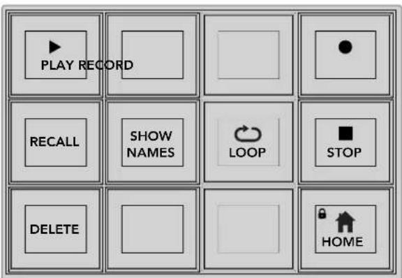
Most of the menu buttons in the system control macros menu are also available on the dedicated macros block on the ATEM 2 M/E Broadcast Panel.
Play
When Recall is selected and you have loaded a macro by clicking on a macro button, click the play icon to start playing the macro.
Recall/Recall and Run
Press this button to cycle through the two macro playback modes. When recall is selected, any macro you select for playback will be cued and ready to run as soon as you press the play button. When recall and run is selected, any macro you select for playback will run automatically.
Delete
Select a macro you want to delete, then press the delete button. A message on the system control LED display will ask you to confirm the deletion. Select yes from the button below the LED display. Your macro is now deleted.
Show Names
Press and hold this button to reveal macro names in the source display.
Loop
Press the loop button to turn the loop feature on or off. When loop is on and a macro is played, the macro will repeat until you press stop or turn off the loop feature. If you turn off the loop feature while a macro is running, the macro will run until the end of its recorded sequence.
Stop
When a macro is running, press the stop button to instantly stop the macro.
Home
The home button returns you to the main system control menu soft button layout.
Recording Macros using ATEM 1 M/E Advanced Panel
You can record and run macros using an ATEM 1 M/E Advanced Panel independently of ATEM Software Control. All actions on the ATEM Software Control switcher page can be performed using your hardware panel. If you need to arrange graphics in the media pool, or adjust camera settings, simply access those settings using ATEM Software Control.
The buttons used to record and run macros on the ATEM 1 M/E Advanced Panel are located in the system control buttons. The names of your macro buttons are displayed in the source select names display.
Follow the steps below to create the 'transitions' macro demonstrated earlier using ATEM Software Control. This time you will create a macro in macro slot 2.
1 Press the 'macro' soft button to open the macros LCD menu.
2 Using the 'macro' knob under the LCD, select the macro slot you want to record to. For this example, select slot 2.
3 Press the 'record' soft button at the top of the LCD to start recording. The record icon appears as a red circle. When recording, this icon becomes a red square.
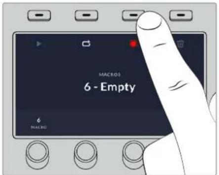
Press the 'record' soft button to start recording your macro
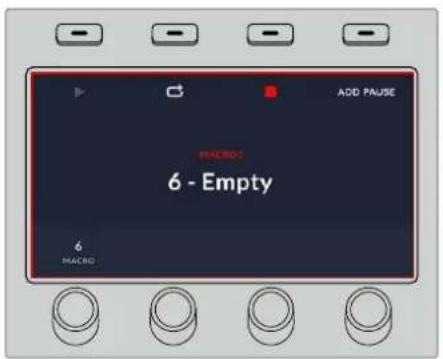
While recording, a red border will appear around the LCD
4 Shift select 'color bars' on the program bus. The button will flash indicating it's a shifted source.
5 Shift select 'color 1' on the preview bus. If you wish, you can map buttons such as color bars, black and color generators to any of the main 10 buttons of the program and preview bus for easier access. See the 'button mapping' section of this manual for instructions.
6 Press the wipe button in transition control to ensure the macro records the wipe transition selection.
7 In the 'wipe' LCD menu, set the rate to 2:00 seconds.
8 Press the 'auto' button in transition control to perform the wipe transition from color bars to color 1.
9 Press the 'macro' button to return to the macro screen.
10 To set the macro to wait for 2 seconds before applying the next transition, press the 'add pause' soft button in the LCD menu and set the duration to 2 seconds by rotating the 'seconds' knob. Press the 'confirm' soft button to record the pause.
11 Now shift select 'black' on the preview bus, press the 'mix' button in transition control and press the 'auto' transition button. Your ATEM switcher will perform a mix transition to black.
12 Press the Macro button to navigate back to the Macro menu, then press the 'record' soft button to stop recording.
You have just recorded a macro using an ATEM 1 M/E Advanced Panel. The macro will appear as a macro button named 'Macro 2' because it is located in macro slot 2. You can name your macro and add notes by clicking on the 'edit macro' button in ATEM Software Control.
To run the macro, press the macro button to set your panel's source select row to macro mode. The buttons will illuminate blue when in macro mode. Now press the macro 2 button. You can easily see when a macro is running because the macro button will flash green and an orange border appears around the LCD menu.
If your macro was successful, you should see your ATEM switcher mix from color bars to color 1 using a 2 second mix transition, pause for 2 seconds, then perform another 2 second mix transition to black, all by pressing one button on your ATEM 1 M/E Advanced Panel. If you want the macro to loop so it keeps running, press the 'loop' soft button to enable loop. Press again to disable loop.
It's worth frequently testing your macros using different switcher settings to make sure the macro performs all the specific functions you intended and doesn't miss any instructions or produce something unexpected.
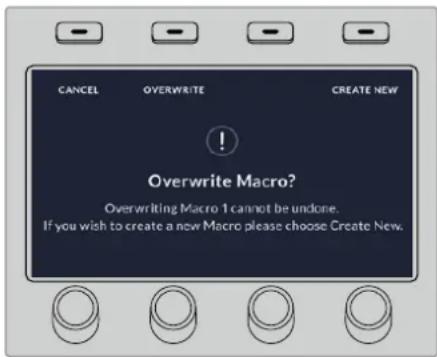
If you want to record over a previously recorded macro, or if you made a mistake and want to start recording the macro again, press the record button and confirm the overwrite when prompted
Using ATEM Camera Control Panel
Traditionally, camera control units, or CCUs, have been designed for mounting inside a desk with independent units for each camera. ATEM Camera Control Panel is a portable solution that can be placed on a desk or solid surface with 4 CCUs built in so you can control up four Blackmagic Design cameras at once. However, you aren't locked into controlling one single camera for each CCU because you can select which camera you want to control.
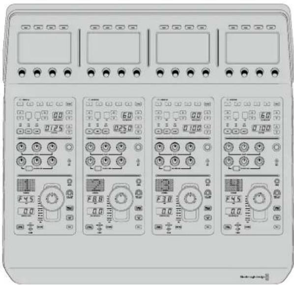
natural_image
Front view of a control panel with multiple display screens and rotary buttons (no readable text or symbols)This means you can control any number of Blackmagic Design cameras using the four CCUs on one single panel, or if you have more than four cameras, you can use additional panels if you want to assign each camera with a dedicated CCU. It's completely up to you.
NOTE Blackmagic Design cameras that can be controlled using ATEM Camera Control Panel include URSA Broadcast, URSA Mini Pro 4.6K, URSA Mini, Blackmagic Studio Camera and Blackmagic Micro Studio Camera.
Powering the Panel
To power your camera control panel, connect power via the IEC power input on the rear panel using a standard IEC power cable. You can also use the 12V DC input if you want to connect external power or redundancy via an external power supply, for example a UPS uninterrupted power supply or external 12V battery.
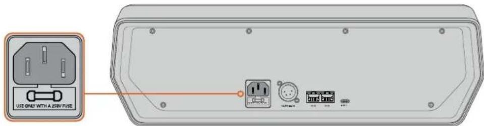
Connect power via the power input on the rear panel
Connecting the Panel to your Switcher
To connect ATEM Camera Control Panel to your switcher, all you need to do is add the panel into your ATEM Ethernet connection chain.
For example, if you are using an external ATEM hardware panel, such as the ATEM 1 M/E Advanced Panel, remove its Ethernet cable from your computer or network and connect it to one of the camera control panel's Ethernet ports instead. The ATEM hardware panel will then be the middle unit in the chain. Now connect the camera control panel's spare Ethernet port to your computer or network.
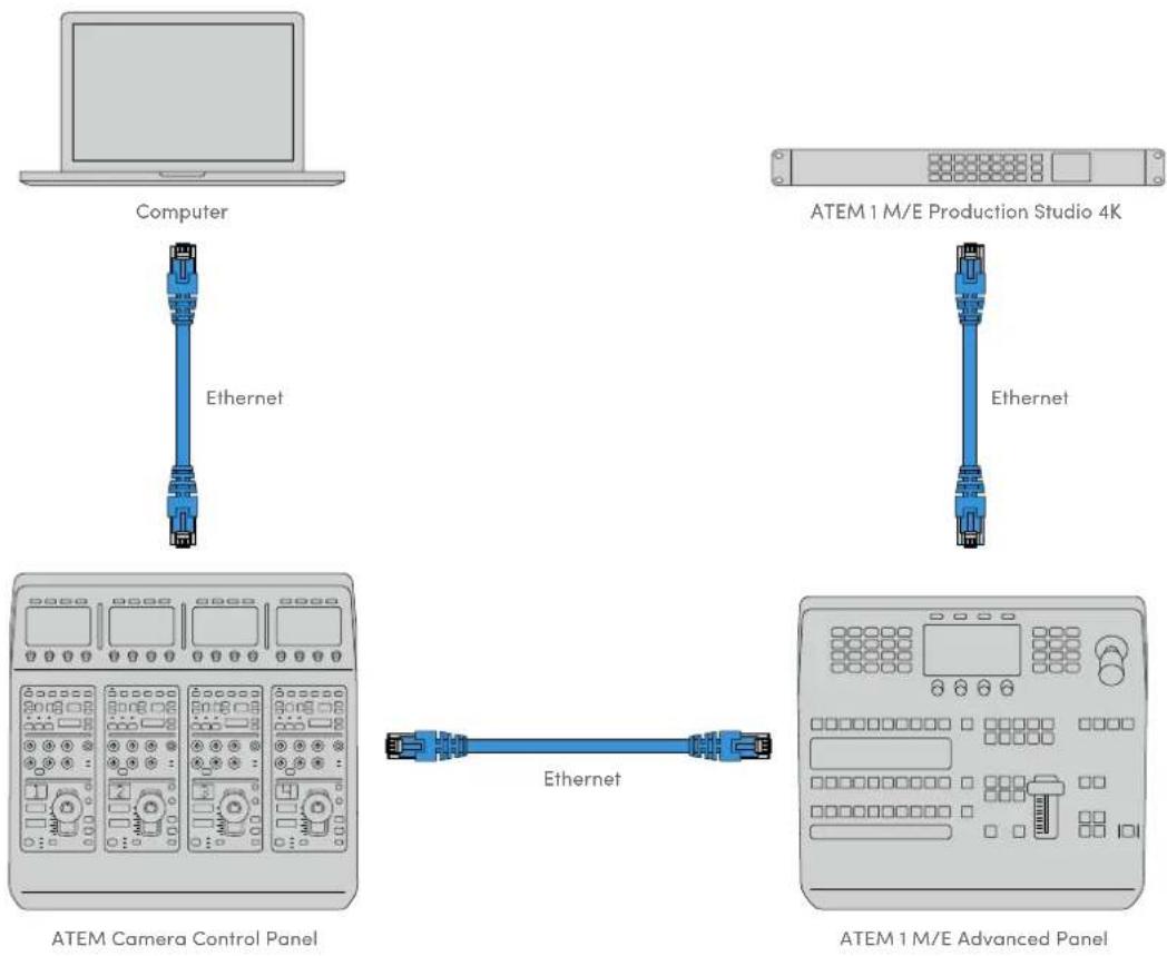
If you are using the camera control panel with just your switcher and a computer on a shared network, connect the panel to your switcher, then the spare Ethernet port to your computer.
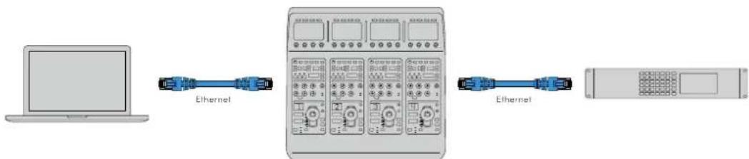
Computer ATEM Camera Control Panel
ATEM 4 M/E Broadcast Studio 4K
After connecting the camera control panel to your ATEM equipment, you should see the lights on the panel illuminate and the LCDs on each CCU will display their respectively assigned cameras. The panel is now powered, connected to your switcher and ready to start controlling your cameras!
The connection process is fast because all the network settings for each ATEM unit have a different default IP address when shipped from the factory. This means when you connect them all to each other, their network settings are automatically configured and will work straight away.
However, if you are adding a camera control panel to an already existing system, or you need to manually assign a different IP address to avoid potential conflicts on your network, you can enable DHCP so your panel determines the best IP address, or disable DHCP and set the IP address manually.
Changing Network Settings
Changing network settings means manually setting the panel's IP address so it can join your network, then entering the switcher's IP address on your panel so the switcher can be identified by your panel. These settings are located in your camera control panel's 'settings' LCD menu.
The home screen is the first menu item you will see on the CCU's LCD. To access the network settings, press the 'settings' soft button.
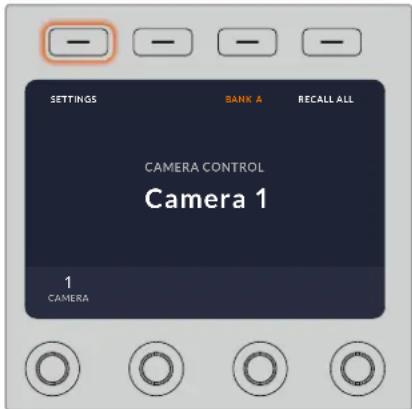
Press the 'settings' soft button on the LCD home screen to access all the camera control panel's settings
The DHCP setting is the first setting in the sequence of menu pages. Under this setting is a row of small dot icons. As you press the arrow soft button to navigate through the pages of settings, the dot icons will illuminate to show which page you are on. All your camera control panel settings are available via these pages.
To set the camera control panel's IP address:
1 If you want the panel to automatically set a compatible IP address, select the DHCP setting by pressing the 'on' soft button.
TIP If you know your network's IP address, you can navigate to the next setting page and check the panel's IP address setting to confirm it has selected an address compatible with your network.
2 If you want to set the IP address manually, make sure the DHCP setting is set to 'off', then press the arrow soft button to navigate to the 'panel IP address' setting.
3 Rotate the corresponding knobs to change the IP address fields.
4 Now press the arrow button to move to the subnet mask and gateway settings and make the necessary changes.
5 Once all the subnet mask and gateway number fields are set, press the 'save changes' soft button to confirm your settings.
With your camera control panel's IP address set, the network can now communicate with your panel.
The next step is to assign the switcher's IP address on the camera control panel. By telling your camera control panel your switcher's IP address, the panel can then identify your switcher on the network.
TIP If your switcher is located near the camera control panel, it's helpful to open the network settings menu on the switcher so you can observe your switcher's IP address while entering the IP address number fields on the camera control panel. This is also a good way to cross check your network settings between each unit.
To set the switcher's IP address on your camera control panel:
1 Press the arrow soft button to navigate to the 'switcher IP address' setting.
2 Using the knobs underneath the LCD, set the numbers for each address field.
3 Press 'save changes' to confirm your settings.
Now that your panel has identified the switcher, all the controls on your panel should illuminate. This lets you know the panel is communicating with your switcher and is now able to control your cameras via the program return SDI outputs from the switcher to each camera.
If the lights are not illuminated on your panel, check your network settings and ensure the Ethernet cables are connected correctly.
Camera Control Panel Layout
Each CCU on your camera control panel is exactly the same with the same controls. The menu settings are primarily controlled using the left CCU's LCD and soft buttons.
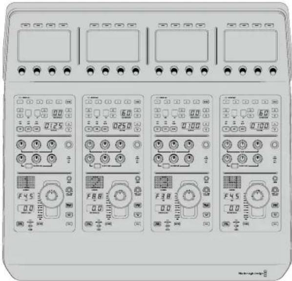
Each CCU has exactly the same controls.
LCD Menu Settings
Pressing the 'home' soft button returns you to main home screen. From the home screen, you can access all your camera control panel's settings including the network settings, auxiliary for camera control, master black enable and disable settings and the brightness settings for adjusting the lights on the various panel controls. You can also identify the software version installed on your camera control panel and the ATEM switcher your panel is connected to.
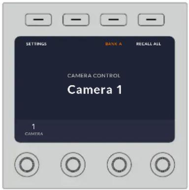
The home screen displays features you may need access to at all times, for example selecting the desired camera bank and recalling scene files for all cameras
Camera Banks A and B
When the LCD is set to the home screen, you will see the camera bank setting at the top of the display. This setting displays which bank of cameras you are controlling.
For example, imagine you are controlling 8 cameras and you want to have a dedicated CCU assigned to each camera. You can assign cameras 1 to 4 for each CCU on bank A, then assign cameras 5 to 8 to each CCU on bank B.
Now when switching your live production, you can press the 'bank' soft button to swap between banks A and B, which lets you instantly access camera control for cameras that have been assigned to dedicated CCUs. This is a faster and more organized way of controlling cameras compared to swapping between multiple cameras on each CCU during production.
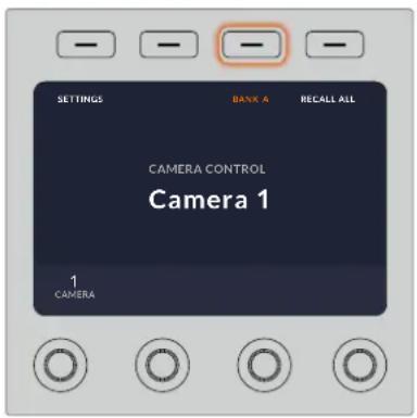
Press the bank soft button to cycle between camera banks A and B, or hold the button down to disable or enable camera banks
You can also disable the banks by holding down the bank soft button until the 'bank off' setting appears on the LCD.
Turning the banks off lets you change the CCUs to other cameras when needed, with a defined set of cameras ready on each bank you can access at any time. To enable banks, simply press the bank button again.
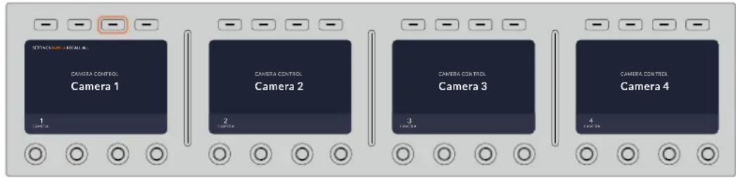
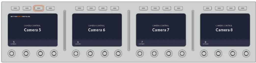
The bank setting lets you assign 2 banks of cameras to the four CCUs and then instantly swap between them by pressing the 'bank' soft button
TIP Any camera can be selected on each CCU in both banks. For example, imagine you want to have constant control over camera 1, even after switching to another bank of cameras. All you need to do is make sure one CCU in each bank always has camera 1 selected.
Settings
Pressing the 'settings' button on the home screen opens all settings for your camera control panel. Navigate through the pages of settings by pressing the arrow soft button. The network settings, including DHCP and IP address settings, are the first pages in the sequence. These settings are described in the section that shows how to change network settings when connecting the camera control panel to your ATEM switcher. Keep reading this section for information on the additional settings for your camera control panel.
Auxiliary Select
Select the auxiliary output you want to assign to camera control. Turn the auxiliary control knob underneath the LCD clockwise or counter clockwise to choose an auxiliary output.
NOTE The auxiliary selection differs depending on which ATEM switcher you are connected to. For example, a switcher with 1 auxiliary output will provide auxiliary 1 or none. A switcher with more auxiliary outputs lets you choose which output to assign to camera control, or select none if you want the auxiliary outputs to be dedicated to other sources. ATEM Constellation 8K lets you choose from any of its outputs.
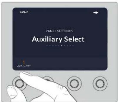
Rotate the auxiliary select knob to assign a dedicated auxiliary output for camera control
Master Black
Setting the master black setting to on or off enables or disables the master black control, also known as the pedestal control. This is helpful if you want to lock the pedestal so it cannot be accidentally adjusted during production. The pedestal is controlled by turning the ring wheel on the joystick control knob clockwise or counter clockwise. More information on the joystick control is provided in the following sections.
Brightness
These settings let you adjust the brightness for the buttons, indicators, LEDs and LCDs on your camera control panel. Rotate the corresponding control knobs for each setting clockwise or counter clockwise to brighten or dim the lights.
CCU Panel Controls
The panel controls for each CCU are separated into three general sections. These include:
Scene Files and Camera Settings
Scene files are for storing all the camera parameters for each CCU. Camera settings can be changed such as shutter speed, master gain, white balance and enabling color bars. More information for these settings, plus the relative and absolute mode settings, are described in detail in the following 'controlling cameras' section.
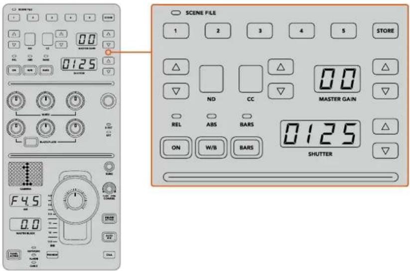
The upper section of each CCU is used to store and recall scene files, plus control camera settings such as shutter speed, master gain, while balance and color bars
Color Balance Controls
The red, green and blue color balance knobs in the panel's mid section are for adjusting the color balance of the lift, gamma and gain levels. The white controls are for adjusting the RGB values for the gain, or highlights and the black controls are for adjusting RGB values of the lift, or the shadows. The black/flare button lets you adjust the RGB values for the gamma, or mid tones, by holding down the button and adjusting the lift RGB knobs.
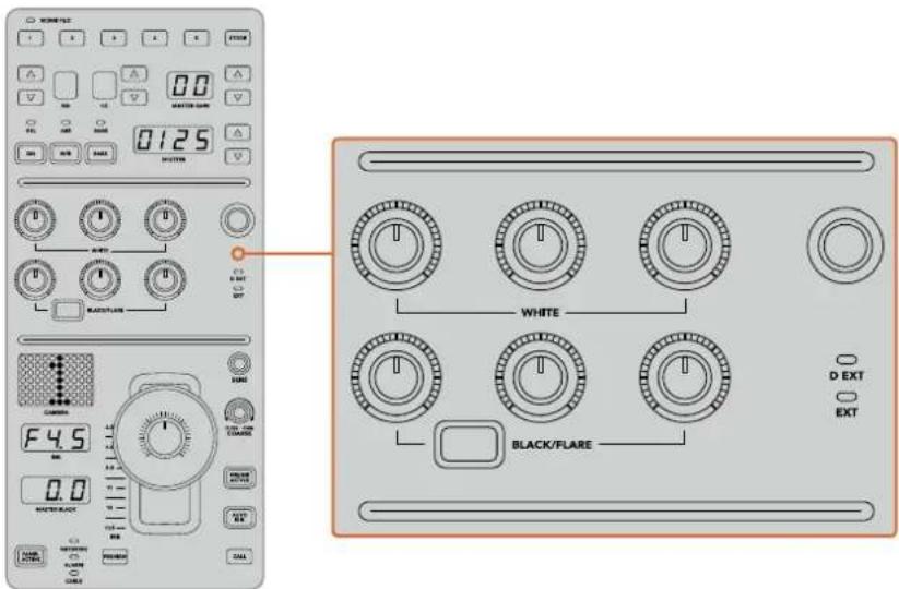
The color balance controls let you make fine adjustments to the red, green, blue channels for the master gain/white, gamma and pedestal/black levels
There is also a custom control that will be uniquely assignable in a future update. Currently, the custom control knob is set to Y gain control. This increases or decreases the overall luminance, or brightness, of the image. More information about color balance control is provided in the following 'controlling cameras' section.
Lens Controls
The lower section of the panel is where most of the control will occur during production.
The first item you will probably notice is the joystick control. This is used to open and close the iris, also known as the white level or gain control and for adjusting the master black level, also known as the pedestal control.
TIP You can also press the joystick down to switch its camera to the auxiliary preview for camera control.
Gain is adjusted by leaning the joystick forwards or backwards to open or close the iris. Increase or decrease the pedestal by rotating the ring wheel underneath the joystick's knob clockwise or counter clockwise. This gives you fine control over both parameters using the same controller.
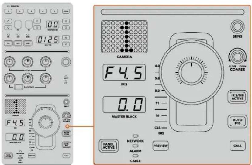
The lower section of the CCU is where most of the camera control occurs during live production
Other buttons and knobs in this section of the CCU are for adjusting the sensitivity of the joystick control, setting the coarse level, locking and unlocking the CCU and more. Details on all the features are provided in the following section.
Controlling Cameras
This section describes all the features on each CCU and a general overview on how to approach camera control.
The first step to controlling cameras is to assign a camera for a CCU.
Assigning a Camera to a CCU
At the bottom of the LCD home screen for each CCU, you will see its camera number displayed and a soft control knob underneath it. Simply turn the knob to change the camera number.
You will also see the camera name change on the LCD. The camera name will illuminate red when on air.
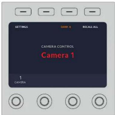
The camera name and number on the LCD home screen shows the camera currently selected for each CCU
TIP The large camera number next to the CCU's joystick control will also change when you assign a camera. This large identifying number is easy to see and will illuminate red when its camera is live on the program output.
natural_image
Abstract pattern of red dots arranged in a vertical column on a gray background (no text or symbols)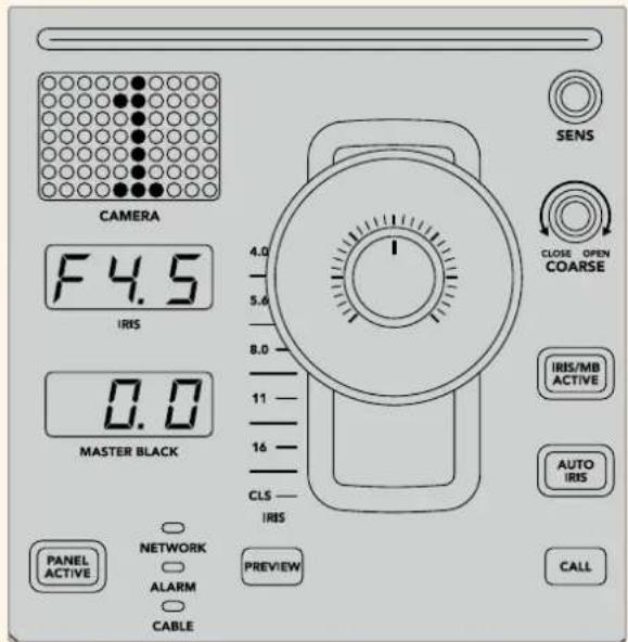
Scene Files
The numbered buttons along the top of each CCU let you quickly store and recall up to 5 scene file presets. For example, once you have arranged all your settings for a camera and you are set up for broadcast, you can then save all the parameters for each camera and recall them later. It's a very fast process!
To store a scene file:
1 Press the 'store' button on a CCU. The button will illuminate red to indicate the panel is ready to store a file.
2 Press a numbered scene file button.
The scene file indicator and buttons will illuminate, indicating when a scene file is stored or recalled.
To recall a scene file:
Press the numbered button for the scene file you want to recall.
That's all you need to do!
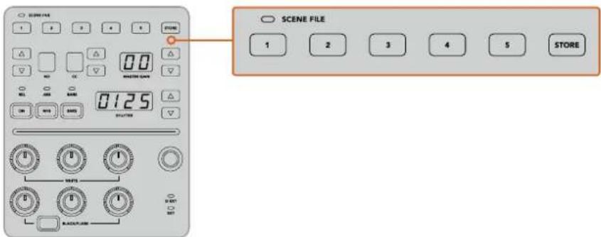
The scene file buttons are used for storing and recalling all settings for CCU controls
Recall All
When this feature is enabled, you can recall a stored scene file on all cameras simultaneously when you press the corresponding scene file button on a single CCU.
For example, you may have a specific setup for each camera that is optimized for a set in your live production. This will likely be a large number of settings that you will want to recall later when you return to that set.
The following is an example of how you can recall complex settings for multiple cameras simultaneously.
To recall a scene file to multiple cameras:
1 Once all your cameras are set up, store a scene file for each camera on scene file 1.
2 Enable the 'recall all' setting by pressing the corresponding soft button in the LCD home menu.
3 Now make any changes you want to each camera.
4 Press the scene file 1 button on any CCU. You will notice that all CCUs have recalled the settings stored in scene file 1 for each independent CCU.
NOTE While this feature is very powerful and helpful, please use with care as it affects all cameras, including the camera switched to the program output. We recommend enabling 'recall all' for specific setups prior to air and then immediately disabling the feature until you need it again.
ND
This setting will be enabled in a future update.
CC
This setting will be enabled in a future update.
Master Gain
Blackmagic Design cameras have ISO and gain settings that can be set using the master gain buttons on the camera control panel. To increase the master gain, press the up arrow next to the master gain indicator. To decrease gain, press the down arrow.
Increasing or decreasing the master gain lets you allow for more light in dimly lit shooting conditions, however it's worth being careful with the master gain as electronic noise can appear in the image as it reaches its highest settings.
TIP When a negative gain value is set, the down arrow will illuminate. When positive gain is set, the up arrow will illuminate.
Relative Control and Absolute Control
The camera control panel has two control modes that determine how the panel maintains synchronization between the physical controls and their settings. The two control modes are relative control and absolute control.
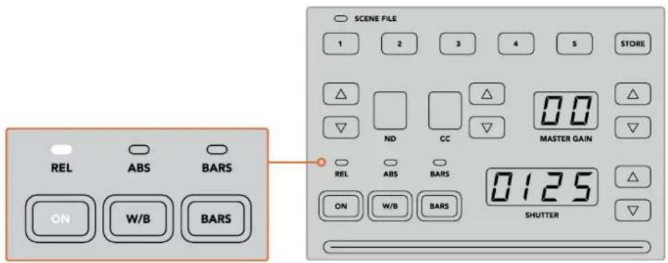
Pressing the 'ON' button repeatedly will cycle between relative and absolute control modes.
Relative Control
In relative control mode, when a setting is adjusted externally and becomes out of sync with the original controller, the next time a change is made to the original controller, its setting will gradually return to sync as the new adjustment is performed.
For example, if the camera's iris is set to f2.8 on the camera control panel and then set to f5.6 using ATEM Software Control, the joystick will still be physically placed at f2.8, but the setting is now f5.6. In relative mode, when you then adjust the joystick to decrease the gain level, the setting will continue from f5.6 and gently return to sync with the controller as you make changes. The process is almost invisible and it's likely you won't even notice.
Absolute Control
In absolute control mode, the settings are always synchronized to their corresponding controls.
NOTE When the panel is in absolute control mode, it's worth keeping in mind that if a control's setting is changed using ATEM Software Control or a different CCU, the next adjustment on the original controller will result in an initially harsh settings change as it snaps back to its originally set position.
For example, if the joystick has set the iris to f2.8 on the camera control panel and then the setting is changed to f5.6 using ATEM Software Control, the next time you adjust the gain level using the joystick, the gain level will immediately snap to f2.8 and begin adjusting from there. That is because the joystick is still positioned at f2.8 on the camera control panel.
For this reason, it's important to decide before going to air which control mode you want to use when controlling your cameras so you can be sure there is no risk of unintended changes when live to air.
White Balance
You can adjust the white balance of each camera by holding down the white balance button, marked 'W/B' and pressing the shutter up and down arrow buttons to warm or cool the image. The shutter setting indicator displays white balance values so you can monitor the color temperature in degrees Kelvin. Check the white balance setting at any time by holding down the white balance button and observing the shutter setting indicator.
TIP When changing a white balance or shutter speed setting, you can increase their speed of change by holding down the corresponding up or down arrow buttons.
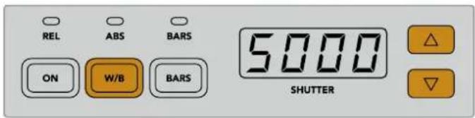
Hold down the W/B button and press the shutter up and down arrow buttons to set a white balance in degrees Kelvin
Color Bars
Pressing the 'bars' button will set the camera to display color bars. Press again to turn bars off.
Shutter Speed
The arrow buttons next to the shutter display let you change the camera's shutter speed. Press the up arrow to increase the shutter speed and down to decrease. For general production use, the shutter speed is typically set to 50, meaning 1/50th of a second, which produces a pleasing motion blur. If you want crisper images with reduced motion blur, for example when shooting sport, a faster shutter speed may be preferred.
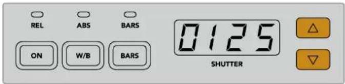
Press the shutter up and down buttons to set the camera's shutter speed
White and Black Balance Controls
The two rows of color balance knobs are used to adjust the color balance of the white and black levels, also known as gain and pedestal. Turn the red, green and blue knobs clockwise or counter clockwise to make changes.
TIP For achieving accurate color settings while adjusting the color balance, it's best to view scopes. For example, a waveform, parade or vectorscope as provided on a Blackmagic SmartScope 4K.
Black/Flare Button
Adjust the color of the gamma or mid tones by holding down the black/flare button and adjusting the black balance RGB controls.
D EXT/EXT
This feature will be enabled in a future update.
Camera Number
Each CCU has its own large camera number that shows you which camera is being controlled. This large display is illuminated green when in a neutral state and red when its camera is switched to the program output.
Gain and Pedestal Level Control
The joystick control lets you make fine adjustments to the gain/iris and pedestal/master black levels.
Leaning the joystick forwards or backwards opens or closes the camera's iris, also known as the gain level. As you lean the joystick forwards and backwards, its indicator strip will illuminate, providing an approximate display of the camera's exposure. For a precise assessment of the exposure f-stop, observe the iris indicator.
Located around the collar of the joystick's handle is a ring wheel that controls the pedestal level. The ring wheel has small ridges built in for firm control and a position indicator is located on the top of the knob to show the physical positioning of the wheel. Turn the wheel clockwise to increase the master black level, or counter clockwise to decrease.
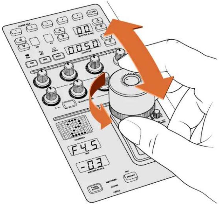
The joystick lets you adjust the gain level by leaning the controller forwards and backwards. The master black level can be adjusted by turning the ring wheel clockwise or counter clockwise. Corresponding Indicators are provided for accurate measurement.
Iris and Master Black Indicators
The indicators for the iris and master black joystick control displays the gain value, shown as the f-stop exposure level for the camera lens and the level of the master black setting.
Preview
When making changes with the camera controls, you can monitor your changes before switching to air by pressing the CCU's preview button. This performs the same function as pressing the joystick, which immediately switches the camera to the dedicated auxiliary output for camera control. This dedicated auxiliary output is set using the 'auxiliary select' setting on your camera control panel, or the general camera control settings in ATEM Software Control.
Sensitivity
The sensitivity setting lets you define a specific range between the highest and lowest gain levels so you can achieve finer control using the joystick. For example, when sensitivity is at its maximum setting, you can lean the joystick all the way forwards or backwards, however it will only affect a narrow range of gain.
You can define how narrow the range is by increasing or decreasing the sensitivity.
Coarse Control Knob
The coarse setting lets you define a limit to the maximum gain control. For example, you may want to ensure your gain never rises higher than a determined exposure.
To do this:
1 Lean the joystick to its highest position to increase the gain setting to its maximum.
2 Now decrease the coarse setting by rotating the coarse knob counter clockwise until the gain reaches the limit you want to set.
You can now lean the joystick all the way up and down and the gain will never rise higher than the limit you have set.
TIP When the coarse control is combined with the sensitivity control, you can define an upper and lower limit to the gain control.
For example, imagine you want to limit the gain so it never rises above f4.0 because gain above that level will clip highlights in your image. You also want to limit the gain so its minimum setting will be f8.0 to maintain the optimum sharpness range for your lens.
To do this:
1 Increase the gain control to its maximum position by leaning the joystick all the way to its top position.
2 Now decrease the coarse setting until it reaches the upper limit you want to set. In this case, f4.0.
3 To set the lower limit, lean the joystick all the way to its bottom position.
4 Now increase the sensitivity setting until the gain reaches the lower limit you want to set. In this case, f8.0.
Now you can lean the joystick all the way from top to bottom and the gain will stay within the limits you have set. This is a powerful way to define your exposure limits, plus gain finer control with the joystick due to allowing its maximum travel forwards and backwards.
Iris and Master Black Active
Once your levels are set and you want to lock them so they are not accidentally changed, press the 'iris/MB active' button. This enables a lock on the gain and master black so that any accidental movements of the joystick will not affect your settings. The 'Iris/MB active' button label will illuminate red when the lock is active. To disable the lock, press the button again.
TIP You can lock the black/pedestal level independently by disabling the 'master black' option in the 'settings' menu. When disabling master black, the black level is locked but the iris/gain level can still be adjusted. Don't forget to enable the master black setting if you want to make changes to the black/pedestal level.
Auto Iris
If your camera is using a compatible lens with electronic iris control via the camera, then you can press the 'auto iris' button for a quick automatic exposure setting. The camera will set exposure based on average brightness, providing an average exposure that is a balance between the brightest highlights and the darkest shadows.
Call
Holding down the ‘call’ button will flash the tally light on the CCU’s selected camera. This is a helpful way of seeking the camera operators’ attention, or to let your operators know you are about to go live.
While holding down the call button, the large camera number next to the joystick will also flash so you can visually confirm the call is being sent.
Panel Active
After you are happy with your camera settings, you may want to lock all the controls so they cannot be accidentally adjusted. Pressing the 'panel active' button enables the CCU lock so all controls cannot be changed. Press the button again to disable the CCU lock. This can be a helpful feature when you are recording a locked off shot and don't want the setting adjusted by accident, for example a wide shot of a stadium filling as the crowd enters.
ATEM Camera Control Panel is an exciting, practical and efficient way to control
Blackmagic Design cameras in your live production. We believe you will enjoy the experience of hands on camera control using CCUs, which lets you take control of exposure and other camera settings, freeing up your camera operators so they can concentrate on framing and focus.
Using Tally
Sending Tally Signals via a GPI and Tally Interface
Your ATEM switcher can send tally signals to monitors and cameras to make it clear which source is on the program output, i.e. which source is on air.
Tally is commonly used to light the red light on top of a camera or monitor so the talent knows they are on air. Tally can also illuminate a border on a monitor such as a Blackmagic SmartView Duo or SmartView HD. The border allows production staff to know which camera is on air.
The GPI and Tally Interface by Blackmagic Design, is an Ethernet device which provides eight mechanical relay contact closures to ground that can be used for tally. Tally signals are sent from the Ethernet port of your ATEM switcher to a GPI and Tally Interface on the same network as the switcher. By following the wiring guide on the back of the GPI and Tally Interface, a breakout cable can be connected to video equipment that supports contact closure tally signals, such as Blackmagic SmartView Duo and SmartView HD. Up to 8 tally receiving devices can be supported with a single GPI and Tally Interface. Only one GPI and Tally Interface unit is needed when used with an ATEM switcher that has 1 M/E. Up to 3 units will be needed for the 20 inputs of the ATEM 4 M/E Broadcast Studio 4K and 2 M/E Production Studio 4K.
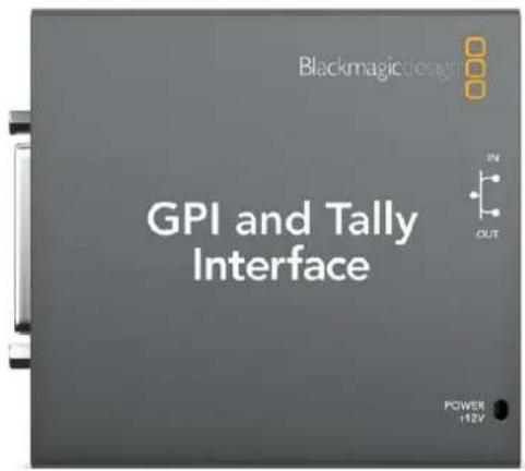
GPI and Tally Interface
The GPI inputs are optical isolators which are triggered by connection to ground with a maximum of 5V at 14mA.
The tally outputs are mechanical relay contact closures to ground with a maximum of 30V at 1A.
The following table illustrates which tally signal is sent when a switcher input is selected on the program output. When using GPI and Tally Interface with an ATEM 2 M/E Production Switcher, use Blackmagic ATEM Setup to set one unit to signal on tally outputs 1 - 8 and the second unit to signal on tally outputs 9 - 16.
| Program Output Tally signal Program Output Tally signal | ||
| Switcher Input 1 Tally 1 Switcher Input 9 Tally 9 | ||
| Switcher Input 2 Tally 2 Switcher Input 10 Tally 10 | ||
| Switcher Input 3 Tally 3 Switcher Input 11 Tally 11 | ||
| Switcher Input 4 Tally 4 Switcher Input 12 Tally 12 | ||
| Switcher Input 5 Tally 5 Switcher Input 13 Tally 13 | ||
| Switcher Input 6 Tally 6 Switcher Input 14 Tally 14 | ||
| Switcher Input 7 Tally 7 Switcher Input 15 Tally 15 | ||
| Switcher Input 8 Tally 8 Switcher Input 16 Tally 16 | ||
Changing the Network and Tally Settings
Blackmagic ATEM Setup is used to configure the network settings in the GPI and Tally Interface so it will communicate with your ATEM switcher. The GPI and Tally Interface must be connected via USB in order to configure its settings with the Blackmagic ATEM Setup.
1 Connect the GPI and Tally Interface to the same Ethernet network as your ATEM switcher.
2 Connect the GPI and Tally Interface to a USB port on your computer and also connect the included power supply.
3 Launch the Blackmagic ATEM Setup.
4 If your ATEM switcher connects directly to your computer or ATEM broadcast panel without an Ethernet network switch, choose to "Configure Address Using Static IP". The GPI and Tally Interface defaults to a fixed IP address of 192.168.10.2 when shipped and we suggest you use this number for simplicity. If you are using two GPI and Tally Interface units with an ATEM 2 M/E Production Switcher, we suggest setting the second unit to 192.168.10.3.
If you want to choose a different static IP address, you can set it to anything you like that's in the same range as the ATEM switcher, so long as it's not already in use by another device on your network. Default IP addresses for ATEM products are best avoided for this reason, including: 192.168.10.1, 192.168.10.2, 192.168.10.3, 192.168.10.10, 192.168.10.50, 192.168.10.60 and 192.168.10.240.
If your ATEM switcher connects via an existing Ethernet network switch, you may wish to choose "Configure Address Using DHCP" as this setting automatically obtains the IP Address, Subnet Mask and Gateway information from your DHCP server.
5 Type in the IP address of your ATEM switcher in the "Switcher Address" field. Your ATEM switcher defaults to a fixed IP address of 192.168.10.240 when shipped and this is the number you should type in this field unless you have changed it.
6 "Set tally outputs" should be set to "Switcher Inputs 1-8" unless you are configuring a second unit to provide tally outputs for switcher inputs 9-16 of an ATEM 2 M/E Production Switcher.
7 Click "Apply". The white LED to the right of the USB port should stop flashing and remain on to indicate it has successfully found the ATEM switcher. The GPI and Tally Interface is now ready.
8 Close Blackmagic ATEM Setup and disconnect your USB cable.
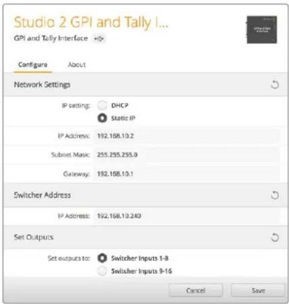
Network and Tally Settings for the GPI and Tally Interface
Using Audio
Connecting other Audio Sources
All ATEM production switchers feature standard balanced XLR or TRS audio inputs and outputs. TRS connectors are also known as 1/4 inch jacks. XLR and TRS inputs are balanced, designed to reduce interference and noise, especially when long cable lengths are required.
If your ATEM switcher has unbalanced RCA audio inputs, you can connect your external audio source directly. RCA audio connectors are useful when using audio from consumer equipment such as a HiFi system or iPod.
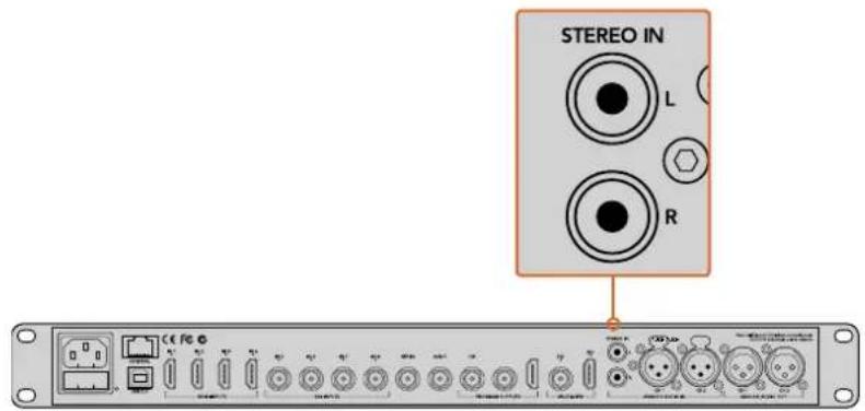
Plug external HiFi audio into your switcher via the RCA inputs
Unique to ATEM 4 M/E Broadcast Studio 4K and ATEM 2 M/E Production Studio 4K are line level, balanced XLR input and output for talkback, designed for connecting to existing talkback systems. This model also features XLR input and output for timecode. Standard SMPTE linear timecode is supported and the output is frame synchronized for reliable video and audio timing.
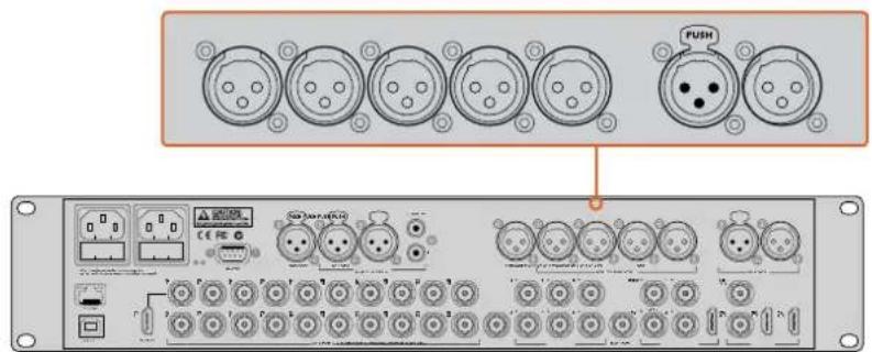
ATEM 2 M/E Production Studio 4K features built in XLR connectors for timecode, audio and talkback
Using Embedded SDI and HDMI Audio Sources
All ATEM switchers include a built-in audio mixer that lets you use the embedded HDMI and SDI audio from your cameras, media servers and other inputs without the need for an external audio mixer.
Once you've connected your SDI and HDMI cameras to the switcher for vision mixing, there are no other connections to make as the audio mixer uses the embedded audio in the video signal. This saves space and makes setup very fast and low cost as you don't need separate audio connections for every video source. You don't need an external audio mixer unless you prefer to use one.
The audio is mixed in the Audio tab of ATEM Software Control and output over the SDI and HDMI program outputs as embedded digital audio.
All ATEM switchers feature XLR or 1/4 inch jacks that let you monitor mixed audio on the monitor XLR or TRS output. The audio mixer contains independent controls for setting the monitor audio level and also for selecting solo audio monitoring when working with these ATEM switcher models.
For maximum flexibility, The ATEM 4 M/E Broadcast Studio 4K and 2 M/E Production Studio 4K feature separate XLR monitor outputs that can be switched into an extra pair of program audio outputs.
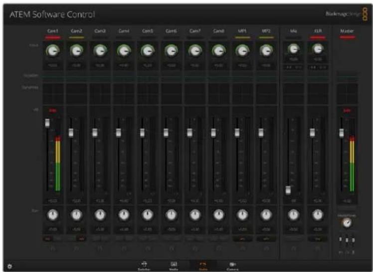
Using MADI with ATEM Constellation 8K
ATEM Constellation 8K supports digital audio with the MADI protocol, also known as Multichannel Audio Digital Interface. MADI is popular with most professional audio manufacturers, broadcasters and high end recording facilities. MADI ports on ATEM Constellation 8K have robust BNC connectors and transmit audio data over 75 ohm coaxial cables up to 100 meters long.
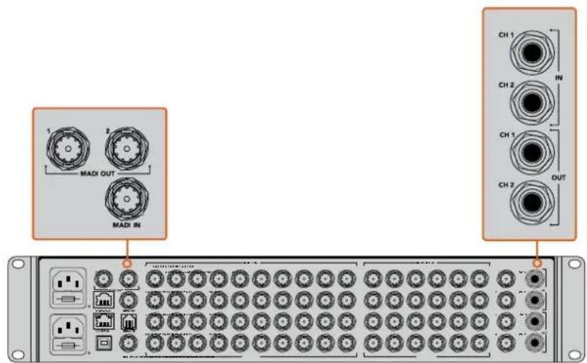
ATEM Constellation 8K has BNC connectors for MADI audio, plus 1/4" TRS connectors for analog audio in and out.
MADI In
MADI channels 1-64 receive digital audio at 24 bit depth with a sampling rate of 48 kHz. These are connected to an extra 64 channels in the audio mixer that you can mix into the program output with the same EQ and dynamics as the video input audio mixing channels. These additional 64 audio inputs mean you can do very complex audio mixing all inside the ATEM Constellation 8K switcher.
MADI Out 1
In 8K mode, MADI Out 1 sends these sources:
Channels 1-10 Channels 1 and 2 of SDI inputs 1-10.
Channel 11 Media player audio.
Channel 12 External mic.
Channel 13 TRS analog audio input.
Channel 14 PGM audio.
In HD and Ultra HD mode, MADI Out 1 sends these sources:
Channels 1-30 Channels 1 and 2 of SDI inputs 1-30.
Channel 31 External mic.
Channel 32 TRS analog audio input.
MADI Out 2
In 8K mode, MADI Out 2 sends these sources:
Channels 1-10 Channels 3 and 4 of SDI inputs 1-10.
Channel 11 Media player audio.
Channel 12 External mic.
Channel 13 TRS analog audio input.
Channel 14 PGM audio.
In HD and Ultra HD mode, MADI Out 2 sends these sources:
Channels 1-30 Channels 3 and 4 of SDI inputs 1-30.
Channel 31 External mic.
Channel 32 PGM audio.
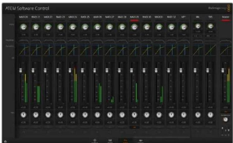
Using a Third Party Audio Mixer Control Surface
Using an Audio Mixer Control Surface
In the fast-paced world of live TV production, using a mouse to make adjustments can sometimes feel too slow! If you need to mix more than one audio source at a time on your ATEM switcher then here's an idea that can really help. Connecting a hardware audio mixer control surface to your ATEM switcher provides you with the ability to use both hands and adjust multiple audio levels at the same time.
An audio mixer control surface can be connected to your Mac or PC as a MIDI device using Mackie Control commands to communicate with the ATEM switcher.
Many third party MIDI control surfaces are compatible with your ATEM switcher but please check with the manufacturer of your control surface if in doubt.
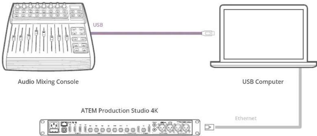
flowchart
graph LR
    A["Audio Mixing Console"] -->|USB| B["Laptop"]
    C["ATEM Production Studio 4K"] -->|Ethernet| B
    style A fill:#f9f,stroke:#333
    style B fill:#ccf,stroke:#333
You can adjust multiple audio levels at the same time by connecting a hardware audio mixer to the computer which is running ATEM Software Control.
Connecting Your Audio Mixer Control Surface
1 Connect your compatible MIDI control surface to your Mac or PC. Most modern control surfaces use USB.
2 Verify your control surface is recognized by your computer as a MIDI device.
For Mac computers, go to Applications/Utilities/Audio MIDI Setup and launch the application. Go to the Window menu and choose Show MIDI Window. Ensure your control surface appears as a MIDI device in this window.
For Windows computers, go to Device Manager/Sound, Video and Game Controllers and ensure your control surface appears in the list of icons.
3 The ATEM audio mixer is designed to communicate with your control surface using Mackie Control commands so your control surface will need to support Mackie Control. You'll also need to make sure your control surface is configured to use native Mackie Control or Mackie Control emulation. Please refer to your control surface's user manual for configuration details.
Some control surfaces offer several types of Mackie Control emulation and you should choose the one that activates the most features on your control surface. For example, with the Behringer BCF 2000, choosing "Mackie Control Mapping for Cakewalk Sonar 3 [MCSo]" enables level faders, bank selectors, balance control, AFV and ON/MUTE functions and also activates the LED screen which displays which bank of faders you have selected for your audio mix. The LED screen will not activate if you choose another Mackie Control emulation.
4 Launch ATEM Software Control and it will automatically look for your control surface using the first port on the first MIDI device that it finds. Click on the Audio tab in ATEM Software Control to display the ATEM audio mixer. Try sliding the gain faders up and down on your hardware control surface and verify that the audio mixer faders show a corresponding increase and decrease in the software on your computer screen. If so, you have successfully configured your control surface to work with the ATEM switcher.
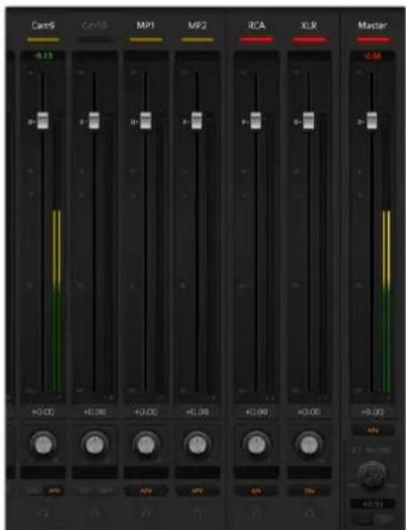
Try sliding the gain faders up and down on your hardware control surface and verify that the audio mixer faders show a corresponding movement in the software on your computer screen
The MUTE button
In the ATEM audio mixer interface, audio is always on, or present in the mix, when the ON button is selected. When the ON button is deselected, audio is not present or is muted. To match the software interface, you'll find the MUTE button on your audio mixer control surface will be lit when audio is always on or present in the mix. The MUTE button will be unlit when audio is not present or is muted.
Decibel Scales
All hardware mixers are made differently and the scale printed on your control surface may not match the scale in the ATEM audio mixer interface. Always refer to the ATEM audio mixer levels for the true decibel scales.
Adapter Cables for Talkback and Camera Control
Talkback Pin Connections
The 'talkback' connector on the back panel of ATEM Constellation 8K is for routing engineering talkback and production talkback. You can make an adapter cable with an RJ45 connector using this pinout diagram.
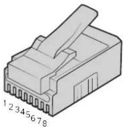
natural_image
Isometric illustration of a 12-pin electrical connector (no text or symbols)| Eng TX+ Eng TX- Prod | TX+ Prod RX+ | Prod RX- Prod TX- Eng RX+ Eng RX- | ||
| 1234 | 5678 |
RJ45 pinout for 'talkback' connector on the back panel of ATEM Constellation 8K
Serial Port Pin Connections for Control Cables
RS-422 Pin Connections for Control Cables
RS-422 is a broadcast standard using a common DE 9 or RJ12 connector. You can easily rewire these types of connectors in a custom built PTZ control unit if you want to design one yourself.
A pinout diagram of the RS-422 DE 9 and RJ12 connector is provided below.
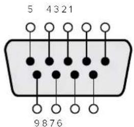
| Receive (-) | Receive (+) | Transmit (-) | Transmit (+) | Ground Pins |
| 8 | 3 | 2 | 7 | 1, 4, 6, 9 |
RS-422 PTZ pin connections.
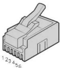
natural_image
Isometric illustration of a 4-pin network connector (no text or symbols)| TX+ | TX- | GND | GND | RX- | RX+ |
| 1 | 2 | 3 | 4 | 5 | 6 |
RJ12 Pinout for PTZ remote on ATEM Constellation 8K
Developer Information
Blackmagic SDI Camera Control Protocol
Version 1.3
If you are a software developer you can use the SDI Camera Control Protocol to construct devices that integrate with our products. Here at Blackmagic Design our approach is to open up our protocols and we eagerly look forward to seeing what you come up with!
Overview
The Blackmagic SDI Camera Control Protocol is used by ATEM switchers, Blackmagic 3G-SDI Shield for Arduino and the Blackmagic Camera Control app to provide Camera Control functionality with supported Blackmagic Design cameras. Please refer to the 'Understanding Studio Camera Control' chapter section of this manual, or the ATEM Switchers Manual and SDK manual for more information. These can be downloaded at www.blackmagicdesign.com/support.
This document describes an extensible protocol for sending a uni directional stream of small control messages embedded in the non-active picture region of a digital video stream. The video stream containing the protocol stream may be broadcast to a number of devices. Device addressing is used to allow the sender to specify which device each message is directed to.
Assumptions
Alignment and padding constraints are explicitly described in the protocol document. Bit fields are packed from LSB first. Message groups, individual messages and command headers are defined as and can be assumed to be 32 bit aligned.
Blanking Encoding
A message group is encoded into a SMPTE 291M packet with DID/SDID x51/x53 in the active region of VANC line 16.
Message Grouping
Up to 32 messages may be concatenated and transmitted in one blanking packet up to a maximum of 255 bytes payload. Under most circumstances, this should allow all messages to be sent with a maximum of one frame latency.
If the transmitting device queues more bytes of message packets than can be sent in a single frame, it should use heuristics to determine which packets to prioritize and send immediately. Lower priority messages can be delayed to later frames, or dropped entirely as appropriate.
Abstract Message Packet Format
Every message packet consists of a three byte header followed by an optional variable length data block. The maximum packet size is 64 bytes.
| Destination device (uint8) | Device addresses are represented as an 8 bit unsigned integer. Individual devices are numbered 0 through 254 with the value 255 reserved to indicate a broadcast message to all devices. |
| Command length (uint8) | The command length is an 8 bit unsigned integer which specifies the length of the included command data. The length does NOT include the length of the header or any trailing padding bytes. |
| Command id (uint8) | The command id is an 8 bit unsigned integer which indicates the message type being sent. Receiving devices should ignore any commands that they do not understand. Commands 0 through 127 are reserved for commands that apply to multiple types of devices. Commands 128 through 255 are device specific. |
| Reserved (uint8) | This byte is reserved for alignment and expansion purposes. It should be set to zero. |
| Command data (uint8[]) | The command data may contain between 0 and 60 bytes of data. The format of the data section is defined by the command itself. |
| Padding (uint8[]) | Messages must be padded up to a 32 bit boundary with 0x0 bytes.Any padding bytes are NOT included in the command length. |
Receiving devices should use the destination device address and or the command identifier to determine which messages to process. The receiver should use the command length to skip irrelevant or unknown commands and should be careful to skip the implicit padding as well.
Defined Commands
Command 0 : change configuration
| Category (uint8) | The category number specifies one of up to 256 configuration categories available on the device. |
| Parameter (uint8) | The parameter number specifies one of 256 potential configuration parameters available on the device. Parameters 0 through 127 are device specific parameters. Parameters 128 though 255 are reserved for parameters that apply to multiple types of devices. |
| Data type (uint8) | The data type specifies the type of the remaining data. The packet length is used to determine the number of elements in the message. Each message must contain an integral number of data elements. |
Currently defined values are:
| 0: void / boolean | A void value is represented as a boolean array of length zero.The data field is a 8 bit value with 0 meaning false and all other values meaning true. |
1: signed byte Data elements are signed bytes
2: signed 16 bit integer Data elements are signed 16 bit values
3: signed 32 bit integer Data elements are signed 32 bit values
4: signed 64 bit integer Data elements are signed 64 bit values
5: UTF-8 string Data elements represent a UTF-8 string with no terminating character.
Data types 6 through 127 are reserved.
| 128: signed 5.11 fixed point | Data elements are signed 16 bit integers representing a real number with 5 bits for the integer component and 11 bits for the fractional component.The fixed point representation is equal to the real value multiplied by 2^11 .The representable range is from -16.0 to 15.9995(15 + 2047/2048). |
Data types 129 through 255 are available for device specific purposes.
| Operation type (uint8) | The operation type specifies what action to perform on the specified parameter. Currently defined values are: |
| 0: assign value | The supplied values are assigned to the specified parameter. Each element will be clamped according to its valid range. A void parameter may only be 'assigned' an empty list of boolean type. This operation will trigger the action associated with that parameter. A boolean value may be assigned the value zero for false and any other value for true. |
| 1: offset / toggle value | Each value specifies signed offsets of the same type to be added to the current parameter values. The resulting parameter value will be clamped according to their valid range. It is not valid to apply an offset to a void value. Applying any offset other than zero to a boolean value will invert that value. |
Operation types 2 through 127 are reserved.
Operation types 128 through 255 are available for device specific purposes.
| Data (void) | The data field is 0 or more bytes as determined by the data type and number of elements. |
The category, parameter, data type and operation type partition a 24 bit operation space.
| Group | ID | Parameter | Type | Index | Minimum | Maximum | Interpretation |
| Lens | 0.0 | Focus | fixed16 | - | 0 | 1 | 0.0 = near, 1.0 = far |
| 0.1 | Instantaneous autofocus | void | - | - | - | trigger instantaneous autofocus | |
| 0.2 | Aperture (f-stop) | fixed16 | - | -1 | 16 | Aperture Value (where fnumber = sqrt(2^AV)) | |
| 0.3 | Aperture (normalised) | fixed16 | - | 0 | 1 | 0.0 = smallest, 1.0 = largest | |
| 0.4 | Aperture (ordinal) | int16 | - | 0 | n | Steps through available aperture values from minimum (0) to maximum (n) | |
| 0.5 | Instantaneous auto aperture | void | --- | trigger instantaneous auto aperture | |||
| 0.6 | Optical image stabilisation | boolean | - | - | - | true = enabled, false = disabled | |
| 0.7 | Set absolute zoom (mm) | int16 | - | 0 | max | Move to specified focal length in mm, from minimum (0) to maximum (max) | |
| 0.8 | Set absolute zoom (normalised) | fixed16 - 0 1 | Move to specified focal length: 0.0 = wide, 1.0 = tele | ||||
| 0.9 | Set continuous zoom (speed) | fixed16 - -1 +1.0 | Start/stop zooming at specified rate: -1.0 = zoom wider fast, 0.0 = stop, +1 = zoom tele fast | ||||
| Video | 1.0 Video mode int8 | [0] = frame rate - - 24, 25, 30, 50, 60 | |||||
| [1] = M-rate - - 0 = regular, 1 = M-rate | |||||||
| [2] = dimensions - - | 0=NTSC, 1=PAL, 2=720, 3=1080, 4=2K DCI, 5=2K 16:9, 6=UHD, 7=3k Anamorphic, 8=4k DCI, 9=4k 16:9, 10=4.6k 2.4:1, 11=4.6k | ||||||
| [3] = interlaced | -- | 0 = progressive, 1 = interlaced | |||||
| [4] = Color space | -- 0 = YUV | ||||||
| 1.1 | Gain (up to Camera 4.9) | int8 | 1 | 16 | 1 = 100 ISO, 2 = 200 ISO, 4 = 400 ISO, 8 = 800 ISO, 16 = 1600 ISO | ||
| 1.2 | Manual White Balance | int16 | [0] = color temp | 2500 | 10000 | Color temperature in K | |
| int16 | [1] = tint | -50 | 50 | tint | |||
| 1.3 | Set auto WB | void | - | - | - | Calculate and set auto white balance | |
| 1.4 | Restore auto WB | void | - | - | - | Use latest auto white balance setting | |
| 1.5 | Exposure (us) | int32 | 1 | 42000 | time in us | ||
| 1.6 | Exposure (ordinal) | int16 | - | 0 | n | Steps through available exposure values from minimum (0) to maximum (n) | |
| 1.7 | Dynamic Range Mode | int8 enum | - | 0 | 1 | 0 = film, 1 = video, | |
| 1.8 | Video sharpening level | int8 enum | - | 0 | 3 | 0 = off, 1 = low, 2 = medium, 3 = high | |
| 1.9 | Recording format | int16 | [0] = file frame rate | - | - | fps as integer (eg 24, 25, 30, 50, 60, 120) | |
| [1] = sensor frame rate | - | - | fps as integer, valid when sensor-off-speed set (eg 24, 25, 30, 33, 48, 50, 60, 120), no change will be performed if this value is set to 0 | ||||
| [2] = frame width | -- in pixels | ||||||
| [3] = frame height | -- in pixels | ||||||
| [4] = flags | -- [0] = file-M-rate | ||||||
| - | - | [1] = sensor-M-rate, valid when sensor-off-speed-set | |||||
| -- [2] = sensor-off-speed | |||||||
| -- [3] = interlaced | |||||||
| -- [4] = windowed mode | |||||||
| 1.10 | Set auto exposure mode | int8 | - | 0 | 4 | 0 = Manual Trigger, 1 = Iris, 2 = Shutter, 3 = Iris + Shutter, 4 = Shutter + Iris | |
| 1.11 | Shutter angle | int32 | - | 100 | 36000 | Shutter angle in degrees, multiplied by 100 | |
| 1.12 | Shutter speed | int32 | - | 24 | 2000 | Shutter speed value as a fraction of 1, so 50 for 1/50th of a second | |
| 1.13 | Gain | int8 | - | -128 | 127 | Gain in decibel (dB) | |
| 1.14 | ISO | int32 | - | 0 | 2147483647 | ISO value | |
| Audio | 2.0 Mic level fixed16 – 0 1 | 0.0 = minimum, 1.0 = maximum | |||||
| 2.1 | Headphone level | fixed16 | - | 0 | 1 | 0.0 = minimum, 1.0 = maximum | |
| 2.2 | Headphone program mix | fixed16 | - | 0 | 1 | 0.0 = minimum, 1.0 = maximum | |
| 2.3 | Speaker level | fixed16 | - | 0 | 1 | 0.0 = minimum, 1.0 = maximum | |
| 2.4 | Input type | int8 | - | 0 | 2 | 0 = internal mic, 1 = line level input, 2 = low mic level input, 3 = high mic level input | |
| 2.5 Input levels | fixed16 | [0] ch0 | 0 1 | 0.0 = minimum, 1.0 = maximum | |||
| [1] ch1 0 1 | 0.0 = minimum, 1.0 = maximum | ||||||
| 2.6 | Phantom power | boolean | - | - | - | true = powered, false = not powered | |
| Output | 3.0 Overlay enables | uint16 bit field | -- -- | bit flags: [0] = display status, [1] = display frame guides Some cameras don't allow separate control of frame guides and status overlays. | |||
| 3.1 | Frame guides style (Camera 3.x) | int8 | [0] = frame guides style | 0 | 8 | 0 = HDTV, 1 = 4:3, 2 = 2.4:1, 3 = 2.39:1, 4 = 2.35:1, 5 = 1.85:1, 6 = thirds | |
| 3.2 | Frame guides opacity (Camera 3.x) | fixed16 | [1] = frame guide opacity | 0.1 | 1 | 0.0 = transparent, 1.0 = opaque | |
| 3.3 | Overlays (replaces .1 and .2 above from Cameras 4.0) | int8 | [0] = frame guides style | - | - | 0 = off, 1 = 2.4:1, 2 = 2.39:1, 3 = 2.35:1, 4 = 1.85:1, 5 = 16:9, 6 = 14:9, 7 = 4:3, 8 = 2:1 | |
| [1] = frame guide opacity | 0 100 | 0 = transparent, 100 = opaque | |||||
| [2] = safe area percentage | 0 100 | percentage of full frame used by safe area guide (0 means off) | |||||
| [3] = grid style | -- | bit flags: [0] = display thirds, [1] = display cross hairs, [2] = display center dot | |||||
| Display | 4.0 | Brightness | fixed16 | - | 0 | 1 | 0.0 = minimum, 1.0 = maximum |
| 4.1 | Overlay enables | int16 bit field | -- -- | 0x4 = zebra | |||
| -- -- | 0x8 = peaking | ||||||
| 4.2 Zebra level | fixed16 – 0 1 | 0.0 = minimum, 1.0 = maximum | |||||
| 4.3 | Peaking level | fixed16 | - | 0 | 1 | 0.0 = minimum, 1.0 = maximum | |
| 4.4 | Color bars display time (seconds) | int8 | -0 30 | 0 = disable bars, 1-30 = enable bars with timeout (s) | |||
| 4.5 Focus Assist | int8 | [0] = focus assist method | - | - | 0 = Peak, 1 = Colored lines | ||
| [1] = focus line color | - | - | 0 = Red, 1 = Green, 2 = Blue, 3 = White, 4 = Black | ||||
| Tally | 5.0 | Tally brightness | fixed16 | - | 0 | 1 | Sets the tally front and tally rear brightness to the same level. 0.0 = minimum, 1.0 = maximum |
| 5.1 | Front tally brightness | fixed16 | - | 0 | 1 | Sets the tally front brightness.0.0 = minimum, 1.0 = maximum | |
| 5.2 | Rear tally brightness | fixed16 | - | 0 | 1 | Sets the tally rear brightness. 0.0 = minimum, 1.0 = maximum Tally rear brightness cannot be turned off | |
| Reference | 6.0 | Source | int8 enum | - | 0 | 2 | 0 = internal, 1 = program, 2 = external |
| 6.1 | Offset | int32 | - | - | - | +/- offset in pixels | |
| Config- guration | 7.0 | Real Time Clock | int32 | [0] time | - | - | BCD - HHMMSSFF (UCT) |
| [1] date | - | - | BCD - YYYYMMDD | ||||
| 7.1 | System language | string | - | - | - | ISO-639-1 two character language code | |
| 7.2 | Timezone | int32 | - | - | - | Minutes offset from UTC | |
| 7.3 | Location | int64 | [0] latitude | - | - | BCD - s0DDdddddddddddd where s is the sign: 0 = north (+), 1 = south (-); DD degrees, ddddddddddddd decimal degrees | |
| [1] longitude | - | - | BCD - sDDDdddddddddddd where s is the sign: 0 = west (-), 1 = east (+); DDD degrees, ddddddddddddd decimal degrees | ||||
| Color Correction | 8.0 Lift Adjust fixed16 | [0] red | -2 2 default 0.0 | ||||
| [1] green | -2 2 default 0.0 | ||||||
| [2] blue | -2 | 2 default 0.0 | |||||
| [3] luma | -2 | 2 | default 0.0 | ||||
| 8.1 | Gamma Adjust | fixed16 | [0] red | -4 | 4 | default 0.0 | |
| [1] green | -4 | 4 | default 0.0 | ||||
| [2] blue | -4 | 4 default 0.0 | |||||
| [3] luma | -4 | 4 | default 0.0 | ||||
| 8.2 Gain Adjust fixed16 | [0] red | 0 | 16 | default 1.0 | |||
| [1] green | 0 | 16 | default 1.0 | ||||
| [2] blue | 0 16 | default 1.0 | |||||
| [3] luma | 0 | 16 | default 1.0 | ||||
| 8.3 Offset Adjust fixed16 | [0] red | -8 | 8 | default 0.0 | |||
| [1] green | -8 | 8 | default 0.0 | ||||
| [2] blue | -8 | 8 | default 0.0 | ||||
| [3] luma | -8 | 8 | default 0.0 | ||||
| 8.4 Contrast Adjust fixed16 | [0] pivot | 0 | 1 | default 0.5 | |||
| [1] adj | 0 2 | default 1.0 | |||||
| 8.5 | Luma mix | fixed16 | - | 0 | 1 | default 1.0 | |
| 8.6 Color Adjust fixed16 | [0] hue | -11 | default 0.0 | ||||
| [1] sat 0 2 | default 1.0 | ||||||
| 8.7 | Correction Reset Default void | - | - | - | reset to defaults | ||
| Media | 10.0 Codec | int8 enum | [0] = basic codec - - | 1 = DNxHD,2 = ProRes,3 = Blackmagic RAW | |||
| [1] = codec variant | - | - | ProRes:0 = HQ,1 = 422,2 = LT, 3 = Proxy,4 = 444, 5 = 444XQ | ||||
| - | - | Blackmagic RAW:0 = Q0,1 = Q5,2 = 3:1,3 = 5:1,4 = 8:1,5 = 12:1 | |||||
| 10.1 Transport mode int8 | [0] = mode | -- | 0 = Preview,1 = Play,2 = Record | ||||
| [1] = speed | -- | -ve = multiple speeds backwards,0 = pause,+ve = multiple speeds forwards | |||||
| [2] = flags | -- | 1<<0 = loop,1<<1 = play all,1<<5 = disk1 active,1<<6 = disk2 active,1<<7 = time-lapse recording | |||||
| [3] = slot 1 storage medium | - | - | 0 = CFast card,1 = SD,2 = SSD Recorder | ||||
| [4] = slot 2 storage medium | - | - | 0 = CFast card,1 = SD,2 = SSD Recorder | ||||
| PTZ Control | 11.0 | Pan/Tilt Velocity | fixed 16 | [0] = pan velocity -1.0 | 1.0 | -1.0 = full speed left,1.0 = full speed right | |
| [1] = tilt velocity -1.0 | 1.0 | -1.0 = full speed down,1.0 = full speed up | |||||
| 11.1 | Memory Preset | int8 enum | [0] = preset command | - | - | 0 = reset,1 = store location,2 = recall location | |
| int8 | [1] = preset slot | 0.5 - | |||||
Example Protocol Packets
| Operation | Packet Length Byte | ||||||||||||||||
| 0 | 1 | 2 | 3 | 4 | 5 | 6 | 7 | 8 | 9 | 10 | 11 | 12 | 13 | 14 | 15 | ||
| header | data | ||||||||||||||||
| destination | length | command | reserved | category | parameter | type | operation | ||||||||||
| trigger instantaneous auto focus on camera 4 | 8 4 4 0 | 0 0 1 | 0 0 | ||||||||||||||
| turn on OIS on all cameras 12 255 5 0 0 0 6 | 0 0 1 | 0 0 0 | |||||||||||||||
| set exposure to 10 ms on camera 4 (10 ms = 10000 us = 0x00002710) | 12 | 4 | 8 | 0 | 0 | 1 | 5 | 3 | 0 | 0x10 | 0x27 | 0x00 | 0x00 | ||||
| add 15% to zebra level (15 % = 0.15 f = 0x0133 fp) | 12 | 4 | 6 | 0 | 0 | 4 | 2 | 128 | 1 | 0x33 | 0x01 | 0 | 0 | ||||
| select 1080p 23.98 mode on all cameras | 16 | 255 | 9 | 0 | 0 | 1 | 0 | 1 | 0 | 24 | 1 | 3 | 0 | 0 | 0 | 0 | 0 |
| subtract 0.3 from gamma adjust for green & blue (-0.3 ~= 0xfd9a fp) | 16 | 4 | 12 | 0 | 0 | 8 | 1 | 128 | 1 | 0 | 0 | 0x9a | 0xfd | 0x9a | 0xfd | 0 | 0 |
| all operations combined | 76 | 4 | 4 | 0 | 0 | 0 | 1 | 0 | 0 | 255 | 5 | 0 | 0 | 0 | 6 | 0 | 0 |
| 1 | 0 | 0 | 0 | 4 | 8 | 0 | 0 | 1 | 5 | 3 | 0 | 0x10 | 0x27 | 0x00 | 0x00 | ||
| 4 | 6 | 0 | 0 | 4 | 2 | 128 | 1 | 0x33 | 0x01 | 0 | 0 | 255 | 9 | 0 | 0 | ||
| 1 | 0 | 1 | 0 | 24 | 1 | 3 | 0 | 0 | 0 | 0 | 0 | 4 | 12 | 0 | 0 | ||
| 8 | 1 | 128 | 1 | 0 | 0 | 0x9a | 0xfd | 0x9a | 0xfd | 0 | 0 | ||||||
Blackmagic Embedded Tally Control Protocol
Version 1.0 (30/04/14)
This section is for third party developers or users who may wish to add support for the Blackmagic Embedded Tally Control Protocol to their products or system. It describes the protocol for sending tally information embedded in the non-active picture region of a digital video stream.
Data Flow
A master device such as a broadcast switcher embeds tally information into its program feed which is broadcast to a number of slave devices such as cameras or camera controllers. The output from the slave devices is typically fed back to the master device, but may also be sent to a video monitor.
The primary flow of tally information is from the master device to the slaves. Each slave device may use its device id to extract and display the relevant tally information.
Slave devices pass through the tally packet on their output and update the monitor tally status, so that monitor devices connected to that individual output may display tally status without knowledge of the device id they are monitoring.
Assumptions
Any data alignment / padding is explicit in the protocol. Bit fields are packed from LSB first.
Blanking Encoding
One tally control packet may be sent per video frame. Packets are encoded as a SMPTE 291M packet with DID/SDID x51/x52 in the active region of VANC line 15. A tally control packet may contain up to 256 bytes of tally information.
Packet Format
Each tally status consists of 4 bits of information:
uint4
bit 0: program tally status (0=off, 1=on)
bit 1: preview tally status (0=off, 1=on)
bit 2-3: reserved (0x0)
The first byte of the tally packet contains the monitor device tally status and a version number.
Subsequent bytes of the tally packet contain tally status for pairs of slave devices. The master device sends tally status for the number of devices configured/supported, up to a maximum of 510.
struct tally
uint8
bit 0: monitor device program tally status (0=off, 1=on)
bit 1: monitor device preview tally status (0=off, 1=on)
bit 2-3: reserved (0b00)
bit 4-7: protocol version (0b0000)
uint8[0]
bit 0: slave device 1 program tally status (0=off, 1=on)
bit 1: slave device 1 device preview tally status (0=off, 1=on)
bit 2-3: reserved (0b00)
bit 4: slave device 2 program tally status (0=off, 1=on)
bit 5: slave device 2 preview tally status (0=off, 1=on)
bit 6-7: reserved (0b00)
uint8[1]
bit 0: slave device 3 program tally status (0=off, 1=on)
bit 1: slave device 3 device preview tally status (0=off, 1=on)
bit 2-3: reserved (0b00)
bit 4: slave device 4 program tally status (0=off, 1=on)
bit 5: slave device 4 preview tally status (0=off, 1=on)
bit 6-7: reserved (0b00)
• • •
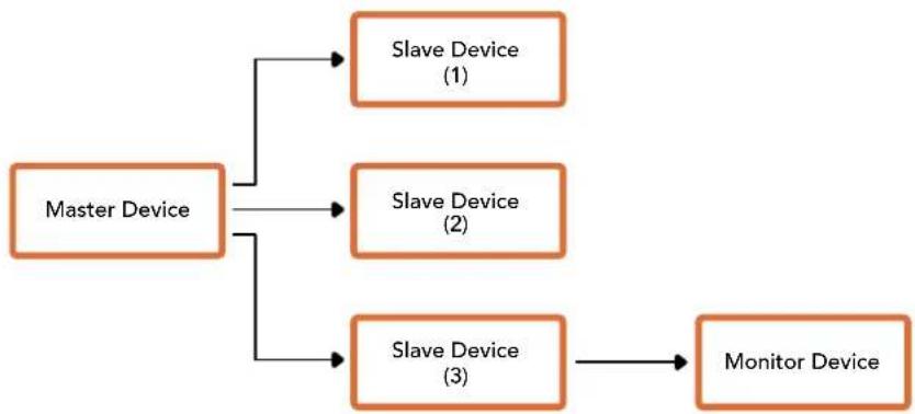
flowchart
graph TD
    A["Master Device"] --> B["Slave Device (1)"]
    A --> C["Slave Device (2)"]
    A --> D["Slave Device (3)"]
    D --> E["Monitor Device"]
| Byte 7 MSB 6 5 4 3 2 1 0 LSB | ||||||||
| 0 | Version(0b0) | Version(0b0) | Version(0b0) | Version(0b0) | Reserved(0b0) | Reserved(0b0) | MonitorPreview | MonitorProgram |
| 1 | Reserved(0b0) | Reserved(0b0) | Slave 1Preview | Slave 1Program | Reserved(0b0) | Reserved(0b0) | Slave 0Preview | Slave 0Program |
| 2 | Reserved(0b0) | Reserved(0b0) | Slave 3Preview | Slave 3Program | Reserved(0b0) | Reserved(0b0) | Slave 2Preview | Slave 2Program |
| 3 ... | ||||||||
Visca Commands for PTZ control via SDI
| Pan-tiltDrive | Up 8x 01 06 01 VV WW 03 01 FF | VV:Pan speed 01 to 18WW:Tilt speed 01 to 17YYYY:Pan position F725 to 08DB(center 0000)ZZZZ:Tilt position FE70 to 04B0(image flip: OFF) (center 0000)Tilt position FB50 to 0190(image flip: ON) (center 0000) | |
| Down 8x 01 06 01 VV WW 03 02 FF | |||
| Left 8x 01 06 01 VV WW 01 03 FF | |||
| Right 8x 01 06 01 VV WW 02 03 FF | |||
| UpDown Left 8x 01 06 01 VV WW 01 01 FF | |||
| UpDown Right 8x 01 06 01 VV WW 02 01 FF | |||
| Down Left 8x 01 06 01 VV WW 01 02 FF | |||
| Down Right 8x 01 06 01 VV WW 02 02 FF | |||
| Stop 8x 01 06 01 VV WW 03 03 FF | |||
| Absolute Position | 8x 01 06 02 VV WWOY OY OY OY OZ OZ OZ OZ FF | ||
| Relative Position | 8x 01 06 03 VV WWOY OY OY OY OZ OZ OZ OZ FF | ||
| Home OY OY OY OY OZ OZ OZ OZ FF | |||
| Reset 8x 01 06 05 FF | |||
| CAM_Memory | Reset 8x 01 04 3F 00 Op FF | p:Memory number (=0 to 5)Corresponds to 1 to 6 on theremote commander. | |
| Set 8x 01 04 3F 01 Op FF | |||
| Recall 8x 01 04 3F 02 Op FF | |||
Compatible motorized heads include the following:
- KXWell KT-PH180BMD
- PTZOptics PT-Broadcaster
- RUSHWORKS PTX Model 1
Help
Getting Help
The fastest way to obtain help is to go to the Blackmagic Design online support pages and check the latest support material available for your ATEM switcher.
Blackmagic Design online support pages
The latest manual, software and support notes can be found at the Blackmagic Design support center at www.blackmagicdesign.com/support.
Contacting Blackmagic Design support
If you can't find the help you need in our support material, please use the "Send us an email" button on the support page to email a support request. Alternatively, click on the "Find your local support team" button on the support page and call your nearest Blackmagic Design support office.
Checking the version currently installed
To check which version of ATEM software is installed on your computer, open the About ATEM Software Control window.
- On Mac, open ATEM Software Control from the Applications folder. Select About ATEM Software Control from the application menu to reveal the version number.
- On Windows, open ATEM Software Control from your 'start' menu. Click on 'help' in the menu bar and select 'about' to reveal the version number.
How to get the latest updates
After checking the version of ATEM software installed on your computer, please visit the Blackmagic Design support center at www.blackmagicdesign.com/support to check for the latest updates. While it is usually a good idea to run the latest updates, it is a wise practice to avoid updating any software if you are in the middle of an important project.
Regulatory Notices
Disposal of Waste of Electrical and Electronic Equipment Within the European Union.

The symbol on the product indicates that this equipment must not be disposed of with other waste materials. In order to dispose of your waste equipment, it must be handed over to a designated collection point for recycling. The separate collection and recycling of your waste equipment at the time of disposal will help conserve natural resources and ensure that it is recycled in a manner that protects human health and the environment. For more information about where you can drop off your waste equipment for recycling, please contact your local city recycling office or the dealer from whom you purchased the product.

This equipment has been tested and found to comply with the limits for a Class A digital device, pursuant to Part 15 of the FCC rules. These limits are designed to provide reasonable protection against harmful interference when the equipment is operated in a commercial environment. This equipment generates, uses and can radiate radio frequency energy and, if not installed and used in accordance with the instructions, may cause harmful interference to radio communications. Operation of this product in a residential area is likely to cause harmful interference, in which case the user will be required to correct the interference at personal expense.
Operation is subject to the following two conditions:
1 This device may not cause harmful interference.
2 This device must accept any interference received, including interference that may cause undesired operation.
ISED Canada Statement
This device complies with Canadian standards for Class A digital apparatus.
Any modifications or use of this product outside its intended use could void compliance to these standards.
Connection to HDMI interfaces must be made with high quality shielded HDMI cables.
This equipment has been tested for compliance with the intended use in a commercial environment. If the equipment is used in a domestic environment, it may cause radio interference.
Safety Information
For protection against electric shock, the equipment must be connected to a mains socket outlet with a protective earth connection. In case of doubt contact a qualified electrician.
To reduce the risk of electric shock, do not expose this equipment to dripping or splashing.
Product is suitable for use in tropical locations with an ambient temperature of up to 40^ C.
Ensure that adequate ventilation is provided around the product and that it is not restricted.
When rack mounting, ensure that the ventilation is not restricted by adjacent equipment.
No operator serviceable parts inside product. Refer servicing to your local Blackmagic Design service center.

Use only at altitudes not more than 2000m above sea level.
State of California statement
This product can expose you to chemicals including hexavalent chromium, which is known to the state of California to cause cancer and birth defects or other reproductive harm.
For more information go to www.P65Warnings.ca.gov.
Warning for Authorized Service Personnel

Disconnect power from both power inlets before servicing!
Caution — Double Pole/ Neutral Fusing
The power supply contained in this equipment has a fuse in both line and neutral conductors and is suitable for connection to the IT power distribution system in Norway.
Warranty
12 Month Limited Warranty
Blackmagic Design warrants that this product will be free from defects in materials and workmanship for a period of 12 months from the date of purchase. If a product proves to be defective during this warranty period, Blackmagic Design, at its option, either will repair the defective product without charge for parts and labor, or will provide a replacement in exchange for the defective product.
In order to obtain service under this warranty, you the Customer, must notify Blackmagic Design of the defect before the expiration of the warranty period and make suitable arrangements for the performance of service. The Customer shall be responsible for packaging and shipping the defective product to a designated service center nominated by Blackmagic Design, with shipping charges pre paid. Customer shall be responsible for paying all shipping charges, insurance, duties, taxes and any other charges for products returned to us for any reason.
This warranty shall not apply to any defect, failure or damage caused by improper use or improper or inadequate maintenance and care. Blackmagic Design shall not be obligated to furnish service under this warranty: a) to repair damage resulting from attempts by personnel other than Blackmagic Design representatives to install, repair or service the product, b) to repair damage resulting from improper use or connection to incompatible equipment, c) to repair any damage or malfunction caused by the use of non Blackmagic Design parts or supplies, or d) to service a product that has been modified or integrated with other products when the effect of such a modification or integration increases the time or difficulty of servicing the product. THIS WARRANTY IS GIVEN BY BLACKMAGIC DESIGN IN LIEU OF ANY OTHER WARRANTIES, EXPRESS OR IMPLIED. BLACKMAGIC DESIGN AND ITS VENDORS DISCLAIM ANY IMPLIED WARRANTIES OF MERCHANTABILITY OR FITNESS FOR A PARTICULAR PURPOSE. BLACKMAGIC DESIGN'S RESPONSIBILITY TO REPAIR OR REPLACE DEFECTIVE PRODUCTS IS THE WHOLE AND EXCLUSIVE REMEDY PROVIDED TO THE CUSTOMER FOR ANY INDIRECT, SPECIAL, INCIDENTAL OR CONSEQUENTIAL DAMAGES IRRESPECTIVE OF WHETHER BLACKMAGIC DESIGN OR THE VENDOR HAS ADVANCE NOTICE OF THE POSSIBILITY OF SUCH DAMAGES. BLACKMAGIC DESIGN IS NOT LIABLE FOR ANY ILLEGAL USE OF EQUIPMENT BY CUSTOMER. BLACKMAGIC IS NOT LIABLE FOR ANY DAMAGES RESULTING FROM USE OF THIS PRODUCT. USER OPERATES THIS PRODUCT AT OWN RISK.
© Copyright 2019 Blackmagic Design. All rights reserved. 'Blackmagic Design', 'DeckLink', 'HDLink', 'Workgroup Videohub', 'Multibridge Pro', 'Multibridge Extreme', 'Intensity' and 'Leading the creative video revolution' are registered trademarks in the US and other countries. All other company and product names may be trade marks of their respective companies with which they are associated.
Thunderbolt and the Thunderbolt logo are trademarks of Intel Corporation in the U.S. and/or other countries.
- Installation and Operation Manual
- ATEM Production Studio Switchers
- Languages
- Welcome
- Grant Petty
- Contents
- Getting Started 6
- Using the ATEM Constellation 8K
- Getting Started
- Introducing ATEM
- What is an M/E Switcher?
- What is an A/B Direct Switcher?
- Understanding the ATEM Switcher
- Plugging in Multi View Monitoring
- Plugging in an ATEM Hardware Panel
- Installing Blackmagic ATEM Software on Mac
- Plugins and Applications that are Installed
- Installing Blackmagic ATEM Software on Windows
- Plugging in your Computer
- To change network settings:
- Switcher Settings
- Set the switcher video standard
- Set Audio Preferences
- Set and Label Video Input Settings
- Customize the Multi View
- Connect a HyperDeck
- Select the Control Panel
- Plugging in Cameras and Other Video Sources
- Plugging in Audio
- Connecting to a Network
- Changing the Switcher Network Settings
- Understanding ATEM Hardware Panel Network Settings
- Setting the Switcher IP Location
- Changing the IP location on an ATEM Broadcast panel
- Changing the IP location on ATEM 1 M/E Advanced Panel
- Changing the Hardware Panel Network Settings
- Changing Network Settings on ATEM Broadcast Panels
- Changing Network Settings on ATEM 1 M/E Advanced Panel
- Setup Workflow with ATEM Constellation 8K
- Updating the Software
- How to update the ATEM Software
- Updating the Switcher Software
- Updating an ATEM Hardware Panel
- Updating via Ethernet
- Connecting Video Outputs
- Video Outputs
- SDI Program Output
- HDMI Program Output
- Multi View SDI and HDMI Output
- Down Converted SDI Program Output
- Auxiliary SDI Outputs
- Preview SDI Output
- M/E Output
- Using the ATEM Constellation 8K Front Panel
- Performing a Transition
- To perform a transition:
- To change the transition type:
- Selecting Other Sources
- To select an alternative program source:
- Changing to Cut Bus Switching
- To change to cut bus mode:
- In Case of Strange Behavior!
- Audio Levels
- To adjust an input audio level, for example on input 4:
- To go back to the master audio level:
- Fading the Downstream Key 1
- Fade to Black
- Using the Lock Button
- Using the LCD Menus
- To use the menus:
- Using Talkback
- The Call Button
- Using ATEM Software Control
- Preference Settings
- General Preferences
- To change the language:
- Button Mapping
- Switcher Control Panel
- Switcher Panel
- Mouse or Trackpad Operation
- Using Keyboard Hot Keys
- Media Manager
- Audio Mixer
- Camera Control
- Using the Software Control Panel
- Mix Effects
- Program Bus Source Select Buttons
- Preview Bus Source Select Buttons
- INPUTS
- BLACK
- SUPERSOURCE
- BARS
- COLOR 1
- MEDIA 1 and 2
- PGM 2
- Transition Control and Upstream Keyers
- CUT
- AUTO/RATE
- Fader Bar
- Transition Style
- PREV TRANS
- Next Transition
- ON AIR
- Downstream Keyers
- TIE
- AUTO
- Fade to Black (FTB)
- Processing Palettes
- Palettes Tab
- Color Generator 1 and 2
- Upstream Keys
- Transitions
- Downstream Key 1 and 2
- Media Players Tab
- Media Players
- Hyperdecks
- Using the Audio Mixer
- Tally
- Audio Level
- Audio Balance
- Audio Source Selection
- Master Audio Level Output
- Audio Mixer Monitor
- Headphones Settings on ATEM Constellation 8K
- Master
- Talkback
- Sidetone
- Shaping your Audio Mix using Advanced Fairlight Controls
- Input Level
- Using the 6 Band Parametric Equalizer
- Parametric Equalizer
- Handles
- Frequency Knobs
- Range Presets
- Gain Knobs
- Q Factor
- Band Filters
- Bell High Shelf Low Shelf
- Notch High Pass Low Pass
- Dynamics Controls
- Common Dynamics Settings
- Expander/Gate
- Compressor
- Make Up
- Limiter
- Fairlight Controls Workflow Guide
- Navigating the Browse Window on the Media Page
- Browsing and loading files
- ATEM Media Pool
- Changing Switcher Settings
- General Settings
- Setting the Switcher Video Standard
- Setting the Multi View Video Standard
- Setting the Down Converter Outputs
- Set 3G SDI Output Level
- Setting the Audio Output Behavior
- SDI Audio Channels 15 and 16
- Mix Minus Settings
- TRS Inputs
- Split Audio
- Adjusting the Media Pool Clip Length
- Camera Control Auxiliary Output
- Multi View Settings
- Labels Settings
- Remote Settings
- Controlling Auxiliary Outputs
- Routing Auxiliary Outputs
- Program/Preview and A/B Direct Transition Control
- Saving and Restoring Switcher Settings
- Saving your Settings
- Restoring your Settings
- Saving your Startup State
- Using Camera Control
- Connecting via SDI
- Connecting via Optical Fiber
- Camera Control Panel
- Camera Control Selection
- Channel Status
- Camera Settings
- Show/Hide Color Bars
- Detail
- Color Wheel
- Master Wheel
- Reset Buttons
- Iris/Pedestal Control
- Zoom Control
- Coarse Setting
- Iris Indicator
- Auto Focus Button
- Manual Focus Adjustment
- Camera Gain
- Shutter Speed Control
- White Balance
- DaVinci Resolve Primary Color Corrector
- Color Wheels
- Click and drag anywhere within the color ring
- Shift-Click and drag within the color ring
- Double-click within the color ring
- Click the reset control at the upper-right of a color ring
- Master Wheels
- To make adjustments using the master wheel:
- Drag the master wheel left or right
- Contrast Setting
- Saturation Setting
- Hue Setting
- Lum Mix Setting
- Synchronizing Settings
- Using a DaVinci Resolve Micro Panel
- To set up a DaVinci Resolve Micro Panel with your ATEM switcher
- Making Color Correction Adjustments
- The Trackballs
- Control Knobs
- HyperDeck Control
- Introducing HyperDeck Control
- Connecting HyperDecks
- HyperDeck Settings
- Auto Roll
- Controlling HyperDecks with ATEM Software Control
- Playback
- Recording
- Controlling HyperDecks with ATEM Hardware Panels
- HyperDeck Setup with ATEM Broadcast Panels
- Configuring auto roll:
- Controlling HyperDecks with ATEM Broadcast Panels
- HyperDeck Multi Control on ATEM 2 M/E Broadcast Panels
- HyperDeck Setup with ATEM 1 M/E Advanced Panel
- Assigning an input to a HyperDeck
- Assigning an IP Address
- Controlling HyperDecks with ATEM 1 M/E Advanced Panel
- Using ATEM Hardware Panels
- ATEM 1 M/E Advanced Panel
- ATEM 1 M/E Broadcast Panel
- ATEM 2 M/E Broadcast Panel
- Using the Control Panel
- Source Name Displays
- Program Bus
- Preview Bus
- SHIFT
- Source Select Bus
- Fader Bar and Fader Bar Indicator
- Transition Type Buttons
- MACRO
- DSK TIE
- DSK CUT
- DSK AUTO
- M/E Numbered Buttons
- FTB
- System Control Menu Buttons
- Joystick and Numeric Keypad
- Controlling Cameras using the Joystick
- Connecting a Remote Head
- PTZ Setup for Remote Heads
- To detect the connected devices:
- PTZ Control via SDI
- Joystick PTZ Controls
- ATEM Broadcast Panel Button Mapping and Button Brightness Level
- Performing Transitions using ATEM Hardware Panels
- Cut Transitions
- To perform a cut transition from the program bus
- CUT Button
- To perform a cut transition using the CUT button
- Auto Transitions
- To perform an auto transition
- Mix Transitions
- To perform a mix transition on an ATEM broadcast panel
- Mix Transition Parameters
- To perform a mix transition on the ATEM 1 M/E Advanced Panel
- Dip Transitions
- To perform a dip transition on an ATEM broadcast panel
- To perform a dip transition on the ATEM 1 M/E Advanced Panel
- Wipe Transitions
- To perform a wipe transition on an ATEM broadcast panel
- To perform a wipe transition on the ATEM 1 M/E Advanced Panel
- DVE Transitions
- To perform a DVE transition on an ATEM broadcast panel
- To perform a DVE transition on the ATEM 1 M/E Advanced Panel
- Sharing DVE resources
- Performing a Graphic Transition
- To perform a graphic transition on an ATEM broadcast panel
- To perform a graphic transition on the ATEM 1 M/E Advanced Panel
- Graphic wipe images
- Manual Transitions
- To perform a manual transition
- Using the ATEM 1 M/E Broadcast Panel
- Source Names Display
- Destination Display and Select Bus
- CUT/FILL
- AUTO and Transition Rate
- System Status
- System Control
- Menu Buttons
- Controlling a HyperDeck
- Using the ATEM 2 M/E Broadcast Panel
- Destination Bus and Select Bus
- DEST SHIFT button
- CUT/KEY
- Auxiliary Outputs
- Transition Style Buttons
- Joystick and M/E Pattern and Key Buttons
- M/E PATT
- M/E KEY
- Controlling Two ATEM Switchers
- To set network location of multiple switchers on the ATEM 2 M/E Broadcast Panel, simply follow these steps for each System Control M/E block:
- Operating your ATEM Switcher
- Internal Video Sources
- Color Bars
- Color Generators
- Controlling media players on the software control panel
- Controlling media players on the broadcast panel
- Performing Transitions
- To perform a cut transition from the program bus on the software control panel
- To perform a cut transition on the software control panel using a keyboard
- To perform a cut transition from the program bus on an ATEM hardware panel
- To perform a cut transition using the CUT button on the software control panel
- To perform a cut transition using the CUT button on an ATEM hardware panel
- To perform an auto transition on the software control panel
- To perform an auto transition on the software control panel using a keyboard
- To perform an auto transition on an ATEM hardware panel
- To perform a mix transition on the software control panel
- To perform a mix transition on an ATEM hardware panel
- To perform a dip transition on the software control panel
- To perform a dip transition on an ATEM hardware panel
- To perform a wipe transition on the software control panel
- To perform a wipe transition on the broadcast panel
- Wipe transition parameters
- Performing a Stinger Transition
- To perform a stinger transition on the software control panel
- Software control panel stinger parameters
- To perform a stinger transition on the broadcast panel
- To perform a stinger transition on the ATEM 1 M/E Advanced Panel
- To perform a DVE transition on the software control panel
- To perform a DVE transition on the broadcast panel
- To perform a graphic transition on the software control panel
- To perform a graphic transition on the broadcast panel
- To perform a manual transition on the software control panel or ATEM hardware panel:
- Preview Transition
- To preview a transition on the software control panel or ATEM hardware panel:
- Keying using ATEM Switchers
- Understanding Keying
- Luma Key
- Linear Key
- Pre multiplied Key
- Performing an Upstream Luma/Linear Key
- To set up a luma/linear key on upstream keyer 1 on the software control panel:
- To set up a luma/linear key on upstream keyer 1 on the broadcast panel:
- To set up a luma/linear key on upstream keyer 1 on the ATEM 1 M/E Advanced Panel:
- Performing a Downstream Luma/Linear Key
- To set up a luma/linear key on downstream keyer 1 on the software control panel:
- To set up a luma/linear key on downstream keyer 1 on the broadcast panel:
- To set up a luma/linear key on downstream keyer 1 on the ATEM 1 M/E Advanced Panel:
- Chroma Key
- Performing an Upstream Chroma Key
- To set up a chroma key on upstream keyer 1 on the software control panel:
- To set up a chroma key on upstream keyer 1 on the broadcast panel:
- To set up a chroma key on upstream keyer 1 on the ATEM 1 M/E Advanced Panel:
- Adjusting parameters with a vectorscope
- Performing an Advanced Chroma Key
- To set up a chroma key on upstream key 1 on the software control panel:
- Fine Tuning your Key using Key Adjustments
- Foreground
- Background
- Key Edge
- Chroma Correction using Color Spill and Flare Suppression
- Spill
- Flare Suppression
- Matching your foreground and background
- Pattern Key
- Performing an Upstream Pattern Key
- To set up a pattern key on upstream keyer 1 on the software control panel:
- To set up a pattern key on upstream keyer 1 on the broadcast panel:
- To set up a pattern key on upstream keyer 1 on the ATEM 1 M/E Advanced Panel:
- Adjusting the x/y position of a pattern
- DVE Key
- Performing an Upstream DVE Key
- To set up a DVE key on upstream keyer 1 on the software control panel:
- To set up a DVE key on upstream keyer 1 on the broadcast panel:
- To set up a DVE key on upstream keyer 1 on the ATEM 1 M/E Advanced Panel:
- Adding DVE Borders
- DVE border styles
- DVE border parameters
- Key Masking
- Fly Key
- Performing Upstream Keyer Transitions
- ON buttons
- Next transition buttons
- Example 1:
- Example 2:
- Example 3:
- Example 4:
- Performing Downstream Keyer Transitions
- Using Adobe Photoshop with ATEM
- Setting up Plug-in Switcher Location
- Preparing Graphics for Download
- Using Auxiliary Outputs
- There are a range of sources available and these include:
- Media Player 1
- Media Player 1 Key
- Media Player 2
- Media Player 2 Key
- Program
- Preview
- Clean Feed 1
- Clean Feed 2
- Using SuperSource (Picture in Picture)
- Setting up SuperSource
- Viewing SuperSource
- Positioning Sources
- Background and Foreground Art
- Adjusting Borders
- Copying Settings
- Putting SuperSource On Air
- Using Macros
- What is a Macro?
- The Macros Window in ATEM Software Control
- Recording Macros
- Recording a Macro using ATEM Software Control
- Building Large Macros
- To compile small macros into a large macro:
- Macros Window Create Page
- Create macro button:
- Arrow buttons and page Icons:
- Edit macro button:
- Delete macro button:
- Macro buttons:
- Status window:
- Macros Window Run Page
- Recall and Run:
- Play:
- Stop:
- Loop:
- Recording Macros using an ATEM 1 M/E Broadcast Panel
- Recording Macros using an ATEM 2 M/E Broadcast Panel
- System Control Macros Menu
- Play
- Recall/Recall and Run
- Delete
- Show Names
- Loop
- Stop
- Home
- Recording Macros using ATEM 1 M/E Advanced Panel
- Using ATEM Camera Control Panel
- Powering the Panel
- Connecting the Panel to your Switcher
- Changing Network Settings
- To set the camera control panel's IP address:
- To set the switcher's IP address on your camera control panel:
- Camera Control Panel Layout
- LCD Menu Settings
- Camera Banks A and B
- Settings
- Auxiliary Select
- Master Black
- Brightness
- CCU Panel Controls
- Scene Files and Camera Settings
- Color Balance Controls
- Lens Controls
- Controlling Cameras
- Assigning a Camera to a CCU
- Scene Files
- To store a scene file:
- To recall a scene file:
- Recall All
- To recall a scene file to multiple cameras:
- ND
- CC
- Master Gain
- Relative Control and Absolute Control
- Relative Control
- Absolute Control
- Shutter Speed
- White and Black Balance Controls
- Black/Flare Button
- D EXT/EXT
- Camera Number
- Gain and Pedestal Level Control
- Iris and Master Black Indicators
- Sensitivity
- Coarse Control Knob
- To do this:
- Iris and Master Black Active
- Auto Iris
- Call
- Panel Active
- Using Tally
- Sending Tally Signals via a GPI and Tally Interface
- Changing the Network and Tally Settings
- Using Audio
- Connecting other Audio Sources
- Using Embedded SDI and HDMI Audio Sources
- Using MADI with ATEM Constellation 8K
- MADI In
- MADI Out 1
- MADI Out 2
- Using a Third Party Audio Mixer Control Surface
- Using an Audio Mixer Control Surface
- Connecting Your Audio Mixer Control Surface
- The MUTE button
- Decibel Scales
- Adapter Cables for Talkback and Camera Control
- Talkback Pin Connections
- Serial Port Pin Connections for Control Cables
- RS-422 Pin Connections for Control Cables
- Developer Information
- Blackmagic SDI Camera Control Protocol
- Version 1.3
- Overview
- Assumptions
- Blanking Encoding
- Message Grouping
- Abstract Message Packet Format
- Defined Commands
- Blackmagic Embedded Tally Control Protocol
- Version 1.0 (30/04/14)
- Data Flow
- Packet Format
- Visca Commands for PTZ control via SDI
- Help
- Getting Help
- Blackmagic Design online support pages
- Contacting Blackmagic Design support
- Checking the version currently installed
- How to get the latest updates
- Regulatory Notices
- Disposal of Waste of Electrical and Electronic Equipment Within the European Union.
- ISED Canada Statement
- Safety Information
- State of California statement
- Warning for Authorized Service Personnel
- Caution — Double Pole/ Neutral Fusing
- Warranty
- Month Limited Warranty
Brand : Blackmagic Design
Model : ATEM 1
Category : Uncategorized