
SRc - Receiver Lectrosonics - Free user manual and instructions
Find the device manual for free SRc Lectrosonics in PDF.


| Product Type | Camera Slot Dual UHF Receiver with Digital Hybrid Wireless® Technology |
| Models | SRc (basic), SRc5P (with front panel audio output) |
| Frequency Bands | A1 (470.100-537.575 MHz), B1 (537.600-614.375 MHz), B2 (563.200-639.975 MHz), Block 606 (606.000-631.500 MHz), C1 (614.400-691.175 MHz), C2 (640.000-713.900/716.775 MHz selectable) |
| Tuning Range | Over 76 MHz covering three standard Lectrosonics frequency blocks |
| Frequency Selection Steps | Selectable: 100 kHz or 25 kHz |
| Receiver Type | Dual conversion, superheterodyne |
| Intermediate Frequencies | Ch.1: 248.450 MHz and 350.000 kHz; Ch.2: 243.950 MHz and 250.000 kHz |
| Frequency Stability | ±0.001% |
| Sensitivity (20 dB SINAD) | 1.0 µV (-107 dBm), A weighted |
| Sensitivity (60 dB Quieting) | 2.2 µV (-100 dBm), A weighted |
| Squelch Quieting | >100 dB typical |
| AM Rejection | >60 dB, 4 µV to 1 Volt |
| Modulation Acceptance | 85 kHz |
| Image and Spurious Rejection | 85 dB |
| Third Order Intercept | 0 dBm |
| Diversity Methods | SmartDiversity™ (phased antenna combining for dual channel) or Ratio Diversity (blends both receivers for single audio channel) |
| Audio Output Level | Adjustable -50 to +5 dBu in 1 dB steps (balanced); unbalanced output 6 dB lower |
| Audio Channels Crosstalk | -80 dB or better |
| Audio Test Tone | 1 kHz, -50 dBu to +5 dBu output (balanced), 1% THD |
| Compatibility Modes | NA HYBR, NU HYBR, MODE 3, 200 SER, 100 SER, JA MODE3, JA HYBR, MODE E, EU HYBR, 300 SER, MODE 7, MODE 6, IFB SER |
| SmartNR (Noise Reduction) | OFF, NORMAL, FULL (available in Digital Hybrid mode only) |
| Antenna Inputs | 50 Ohm; SMA female connectors |
| Power Requirements | Min. 7 V to max. 18 V DC; 2.6 W typical; 145 mA at 18 VDC, 290 mA at 7 VDC |
| Battery Options (with adapters) | NP-F570 slim L series (approx. 12 hours), two 9V alkaline (approx. 5 hours), two 9V Li-Polymer rechargeable (approx. 6 hours) |
| Operating Temperature Range | -20°C to +50°C |
| Weight | 225 grams (7.9 oz) with SREXT adapter |
| Overall Dimensions | 2.92" wide x 1.22" high x 4.93" deep (74 mm x 31 mm x 125 mm) with SREXT adapter |
| Warranty | One year from date of purchase against defects in materials or workmanship |
Frequently Asked Questions - SRc Lectrosonics
User questions about SRc Lectrosonics
0 question about this device. Answer the ones you know or ask your own.
Ask a new question about this device
Download the instructions for your Receiver in PDF format for free! Find your manual SRc - Lectrosonics and take your electronic device back in hand. On this page are published all the documents necessary for the use of your device. SRc by Lectrosonics.
USER MANUAL SRc Lectrosonics
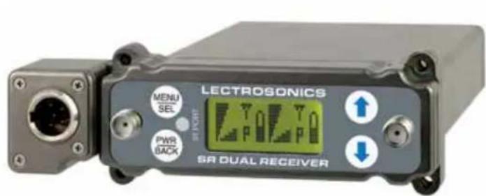
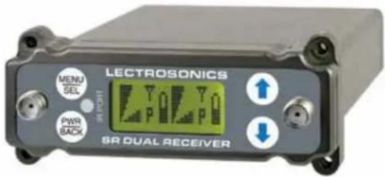
Camera Slot Dual UHF Receiver
Featuring
Digital Hybrid Wireless® Technology
U.S. Patent 7,225,135
Quick Start Summary
The following checklist includes the minimum required settings to start using the receiver.
• Install either a battery sled, camera slot adapter or other power source (see pages 9-13).
- Connect power to the receiver (see pages 11, 12, 15).
- Set the DIVMODE for single or dual channel operation (see page 21).
- Set the COMPAT (compatibility) mode for the transmitters to be used (see page 21).
- Find clear operating frequencies for one or both receivers using SmartTune or manual scanning (see pages 24, 25).


Fill in for your records:
Serial Number:
Purchase Date:
- Set transmitters on the matching frequencies (see transmitter manual).
- Verify transmitters are set to the same compatibility mode as the receiver (see transmitter manual).
- Adjust transmitter input gain to match voice level and mic position (see transmitter manual).
- Adjust receiver output level as needed for the camera or mixer input level desired (see LEVEL on page 21).
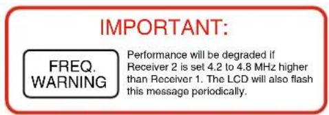

Table of Contents
Wideband Tuning Range....4
Model Differences....4
SRc 4
SRc5P 4
General Technical Description ....5
Front Panel Controls and Functions....8
Audio Outputs 8
LCD Screen 8
MENU/SELECT Button....8
PWR/BACK Button 8
IR (Infrared) Sync ....8
UP/DOWN Arrow Buttons 8
Rear Panel and Adapters....8
Camera Slot Adapters....9
Installing Camera Slot Adapters 9
Adapters for Stand-Alone Use 10
Installing Rear Panel Adapters....10
Replacement Screw Kits....10
Battery Adapters....11
Installing the SRBATTSLED....11
SR9VBP 9 Volt Battery Adapter....12
SRSLEEVE mounting adapter....12
SRHARDWARE mounting adapter kit....12
Audio Output Cables and Connectors....14
External Power Cables....15
Mounting and Orientation....16
AMJ Rev. A Jointed Antenna....17
LCD Main Window....18
Main Window....19
Frequency Screen....19
Setup Screens ....19
Locking and Unlocking the
Front Panel Controls 19
LCD Backlight Setup....19
Battery Timer Reset 19
Navigating the LCD 20
Menu Item Descriptions 21
Front Panel Shortcuts 23
Accessing Block 606....23
Finding Clear Frequencies with SmartTune™....24
Finding Clear Frequencies with Manual Scanning.....25
Scan Window 25
Zoom View Window....25
Pre-coordinated Frequencies....26
Frequency Coordination....27
Multi-channel System Checkout 27
Troubleshooting....28
Specifications and Features....30
Service and Repair....31
Returning Units for Repair ....31
Attestation of Conformity....32
Declaration of Conformity ....33
Digital Hybrid Wireless®
The Lectrosonics Digital Hybrid Wireless ^® uses innovative technology to combine the advantages of digital audio with the advantages of analog RF transmission. The result delivers the superior sound quality of a digital system and the excellent range of an analog system.
A proprietary algorithm encodes the digital audio information into an analog format which can be transmitted in a robust manner over an analog FM wireless link. The receiver employs state-of-the-art filters, RF amplifiers, mixers and detector to capture the encoded signal and a DSP recovers the original digital audio.
This digital/analog hybrid technique has some very beneficial properties. Because the information being transmitted is digitally encoded, immunity to noise is much higher than what a compandor can offer. Because the encoded audio is sent in analog format, spectral and power efficiency and operating range are not compromised.
Under weak RF conditions, the received signal de-grades gracefully, like an analog system, delivering as much usable audio as possible at maximum range. Since the audio is free of compandor artifacts, pumping and breathing problems are also greatly reduced.
Model Differences
SRC
This is the basic receiver with audio outputs on the rear panel only.
Wideband Tuning Range
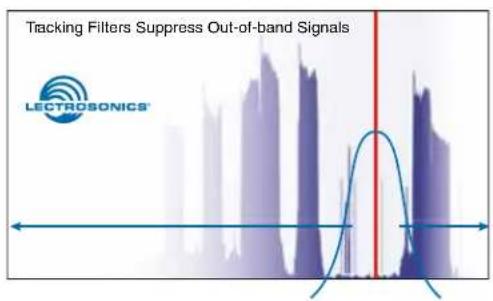
The increased congestion in the UHF television frequency bands has driven the demand for extended tuning ranges in wireless microphone equipment. The goal is to be able to find empty places in the RF spectrum where there is little or no interference. The logic behind this thinking is valid except for the fact that a wideband tuning range allows a greater amount of RF energy from all sources to enter the receiver, This excessive amount of RF energy can easily be enough to overwhelm the receiver and shorten the operating range or cause noise and dropouts.
To allow a wide tuning range and preserve the performance of a narrowband receiver, the SRc Series design employs tracking filters in the front-end section to block RF energy above and below the tuned frequency. The filter automatically adjusts to stay centered over the operating frequency and significantly suppresses out of band RF signals.
SRc5P
An additional audio output is provided next to the front panel for use with cameras that have only one audio input in the mounting slot. When the receiver is used outside of a camera, this extra audio output can be used to feed a recorder or IFB transmitter while the rear panel audio outputs feed a mixer or camera.
General Technical Description
flowchart
graph TD
    A["BPF"] --> B["Tracking"]
    B --> C["LNA"]
    C --> D["Tracking"]
    D --> E["Mixer"]
    E --> F["IF amp"]
    F --> G["SAW filter"]
    G --> H["IF amp"]
    H --> I["SAW filter"]
    I --> J["Rx IC"]
    J --> K["350 kHz"]
    K --> L["Pulse detector"]
    L --> M["Audio 1"]
    L --> N["Window detect"]
    O["Receiver 1"] --> P["Solster"]
    P --> Q["Phase combiner"]
    Q --> R["μP"]
    R --> S["High side injection"]
    S --> T["PLL"]
    T --> U["1st VCO"]
    U --> V["2nd VCO"]
    V --> W["RSSI"]
    X["Receiver 2"] --> Y["Phase combiner"]
    Y --> Z["μP"]
    Z --> AA["High side injection"]
    AA --> AB["PLL"]
    AB --> AC["1st VCO"]
    AC --> AD["2nd VCO"]
    AD --> AE["RSSI"]
    AF["Receiver 2"] --> AG["LNA"]
    AG --> AH["Tracking"]
    AH --> AI["LNA"]
    AI --> AJ["Tracking"]
    AJ --> AK["μP"]
    AK --> AL["Mixer"]
    AL --> AM["IF amp"]
    AM --> AN["SAW filter"]
    AN --> AO["IF amp"]
    AO --> AP["SAW filter"]
    AP --> AQ["Rx IC"]
    AQ --> AR["250 kHz"]
    AR --> AS["Pulse detector"]
    AS --> AT["Audio 2"]
RF PCB Block Diagram
Audio PCB Block Diagram
flowchart
graph TD
    A["Power"] --> B["Fuse"]
    B --> C["DC DC conv"]
    C --> D["Osc sync"]
    D --> E["DC DC conv"]
    E --> F["+1.6V"]
    F --> G["DC-DC conv"]
    G --> H["+3.3V"]
    H --> I["DC-DC conv"]
    I --> J["+30V"]
    J --> K["Ch1 audio switch"]
    K --> L["+5V"]
    L --> M["Diode regulated outputs"]
    K --> N["Ch2 audio switch"]
    N --> O["+5V"]
    O --> P["μP polarity"]
    P --> Q["Digital pot"]
    Q --> R["Audio amps"]
    R --> S["DAC"]
    S --> T["DSP"]
    T --> U["μP"]
    U --> V["Ref xtal"]
    V --> W["LCD display"]
    X["V Reg"] --> Y["To both PLL"]
    Y --> Z["To phase switches"]
    Z --> AA["+3.3V"]
    AA --> AB["Memory"]
    AB --> AC["μP"]
    AC --> AD["DSP"]
    AD --> AE["DAC"]
    AE --> AF["Digital pot"]
    AF --> AG["Ch1 digital attenu"]
    AG --> AH["μP digital atten"]
    AH --> AI["Digital pot"]
    AI --> AJ["Ch1 audio switch"]
    AJ --> AK["+5V"]
    AK --> AL["Diode regulated outputs"]
    AJ --> AM["Ch2 audio switch"]
    AM --> AN["+5V"]
    AN --> AO["μP polarity"]
    AO --> AP["Digital pot"]
    AP --> AQ["Audio amps"]
    AQ --> AR["DAC"]
    AR --> AS["DSP"]
    AS --> AT["MACD"]
    AT --> AU["Audio amps"]
    AU --> AV["DAC"]
    AV --> AW["Digital pot"]
    AW --> AX["Ch1 digital attenu"]
    AX --> AY["μP digital atten"]
    AY --> AZ["Digital pot"]
    AZ --> BA["Audio amps"]
    BA --> BB["DAC"]
    BB --> BC["Digital pot"]
    BC --> BD["Audio amps"]
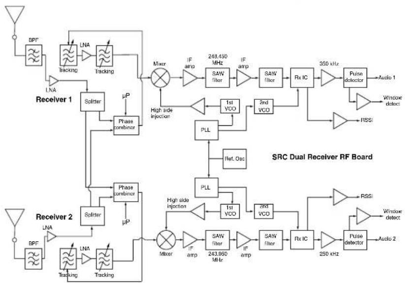
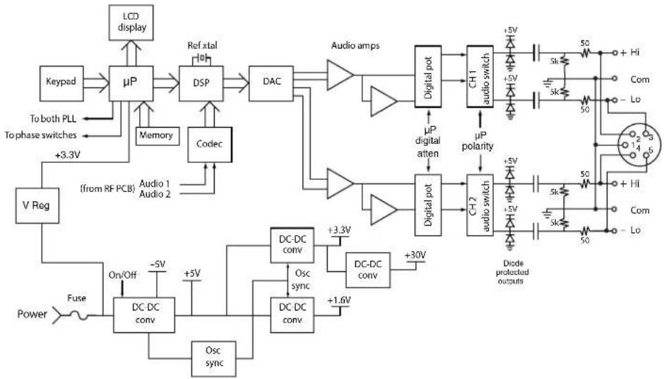
The design consists of two separate receivers built into a single, ultra compact housing with interchangeable adapters for video camera wireless receiver slots and stand-alone use. Digital Hybrid Wireless® technology provides superb, compandor-free audio quality and compatibility with other wireless systems. The RF performance is extremely stable over a very wide temperature range, making the receiver perfectly suited to the rough environmental conditions in field production.
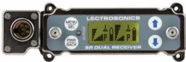
The front panel features a menu-driven LCD interface and four membrane switches used to view and alter settings. Audio outputs are provided on the rear panel for camera slots or other audio devices, on the SRC model, and the SRc5P, model provides a second audio output on the front panel through a 5-pin TA Series connector.
A built-in spectrum analyzer scans across the tuning range of the receiver to simplify finding clear operating frequencies.
The dual receiver architecture allows two different types of diversity reception:
SmartDiversity™ allows each receiver to run independently to provide two separate audio channels. The algorithm analyzes both the incoming RF level and the rate of change in RF level to determine the optimum timing for antenna phase switching. The system also employs “opportunistic switching” to analyze and then latch the phase in the best position during brief squelch activity.
Ratio Diversity blends the audio outputs of both receivers in a seamless manner to produce a single audio output. A panning circuit blends more signal from the receiver with the stronger RF signal over a wide RF level range to anticipate and eliminate dropouts long before they occur. When a good RF signal is present at both receivers and the audio is blended equally, the signal-to-noise ratio is increased by 3 dB.
Three Block Tuning Range
The SRc receiver tunes across a range of over 76 MHz. This tuning range covers three standard Lectrosonics frequency blocks.
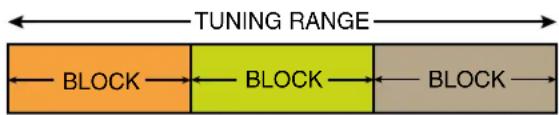
Tuning ranges are available covering standard blocks as follows:
| Band Blocks Covered Freq. (MHz) | ||
| A1 470, 19, 20 470.100 - 537.575 | ||
| B1 21, 22 23 537.600 - 614.375 | ||
| B2 22, 23, 24 563.200 - 639.975 | ||
| Block 606 | 23, 24 | 606.000 - 631.500 |
| C1 24 | 25, 26 614.400 - 691.175 | |
| C2 25, 26, 27 640.000 - 716.775 | ||
To simplify backward compatibility with earlier Digital Hybrid Wireless ^® equipment, block numbers are presented along with frequencies in LCD screens.
RF Front-End with Tracking Filter
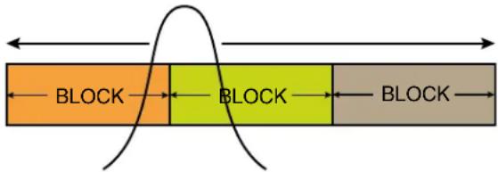
A wide tuning range is helpful in finding clear frequencies for operation, however, it also allows a greater range of interfering frequencies to enter the receiver. The UHF frequency band, where almost all wireless microphone systems operate, is heavily populated by high power TV transmissions. The TV signals are immensely more powerful than a wireless microphone transmitter signal and will enter the receiver even when they are on significantly different frequencies than the wireless system. This powerful energy appears as noise to the receiver, and has the same effect as the noise that occurs with extreme operating range of the wireless system (noise bursts and dropouts). To alleviate this interference, front-end filters are needed in the receiver to suppress RF energy below and above the operating frequency.
The SRc receiver employs a variable frequency, tracking filter in the front-end section (the first circuit stage following the antenna). As the operating frequency is changed, the filters re-tune in fine increments to stay centered over the selected carrier frequency.
flowchart
graph LR
    A["Orange Block"] --> B["Yellow Block"]
    B --> C["Gray Block"]
    style A fill:#f9f,stroke:#333
    style B fill:#ccf,stroke:#333
    style C fill:#cfc,stroke:#333
In the front-end circuitry, a tuned filter is followed by an amplifier and then another filter to provide the selectivity needed to suppress interference. This unique filter design allows a wide tuning range and retains the sensitivity needed for extended operating range.
IF Amplifiers and SAW Filters
The first IF stage employs two SAW (surface acoustic wave) filters. The use of two filters significantly increases the depth of filtering while preserving sharp skirts, constant group delay, and narrow bandwidth. Though expensive, this special type of filter allows primary filtering as early as possible, at as high a frequency as possible, before high gain is applied, to deliver maximum image rejection. These filters are made of quartz, and they are very temperature stable.
In receiver 1, the signal is converted to 248.950 MHz in the first mixer stage, then passed through two SAW filters. After the SAW filters, the signal is converted to 350 kHz and then the majority of the gain is applied.
In receiver 2, the same conversions take place at different frequencies: first to 243.950 MHz, then to 250 kHz.
Although these IF frequencies are unconventional in a wide deviation ( ±75 kHz) system, the design provides excellent image rejection.
Digital Pulse Counting Detector
Following the IF section, the receiver uses an elegantly simple, yet highly effective digital pulse counting detector to demodulate the FM signal to generate the audio, rather than a conventional quadrature detector. This unusual design eliminates thermal drift, improves AM rejection, and provides very low audio distortion. The output of the detector is fed to the microprocessor where a window detector is employed as part of the squelch system.
DSP-Based Pilot Tone
The Digital Hybrid system design uses a DSP generated ultrasonic pilot tone to reliably mute the audio when no RF carrier is present. The pilot tone must be present in conjunction with a usable RF signal before the audio output will be enabled. 256 pilot tone frequencies are used across each 25.6 MHz block within the tuning range of the system. This alleviates erroneous squelch activity in multichannel systems where a pilot tone signal can appear in the wrong receiver via IM (intermodulation).
The pilot tones are repeated with each successive 25.6 MHz increment across the tuning range of units that tune across a 3-block band. These units can tune in either 25 kHz or 100 kHz steps. The pilot tones increment in 100 kHz steps, so the pilot tone will be the same for all four adjacent frequencies in each 100 kHz increment. For example, 550.100, 550.1256, 550.150 and 550.175 MHz will all have the same pilot tone.
Pilot tones are also provided for legacy equipment and some models from other manufacturers.
SmartSquelch™
A DSP-based algorithm called SmartSquelch ^™ optimizes the receiver performance in very weak signal conditions. The RF level and supersonic noise in the audio are continuously monitored to determine the appropriate noise reduction needed and the point at which squelch (complete muting of the audio) is necessary.
As the RF level decreases and supersonic noise in the signal begins to increase, a variable knee, high frequency roll-off filter is applied to suppress high frequency noise. The filtering action moves in and out smoothly to avoid abrupt changes that could be audible. When the RF signal becomes so weak that the receiver can no longer deliver usable audio, the squelch will activate.
SmartDiversity™
Microprocessor controlled antenna phase combining is used for diversity reception. When the incoming RF level drops to a certain point, the phase (polarity) of one antenna is reversed and the resulting level is compared with the one in the previous state. If the level has increased, the phase is retained. If the level has decreased, the phase is reversed back to the previous state.
The logic behind this design is based upon the fact that two antennas mixed in phase will deliver a stronger signal than either antenna by itself. If the antennas are spaced more than a few inches apart, the signals arriving at them will be non-correlated (diverse), to effectively deal with multi-path dropouts.
Turn On and Turn Off Delays
A brief delay is applied when the receiver is powered up or down to prevent audible noise such as a thump, pop, click or other transient noise.
Test Tone
To assist in matching the audio levels of equipment connected to the receiver, a 1 kHz audio test tone generator is provided, with an output level adjustable from -50 to +5 dBu in 1 dB increments.
The tone simulates the audio output with a steady signal at full modulation, making it easy to adjust the level to precisely match the optimal level for the connected device and maximize the signal to noise ratio of the system.
LCD Display
Setup and monitoring is done through the LCD display on the control panel. The built-in backlight for viewing in dimly lit environments can be set to remain on for 30 seconds, 5 minutes or to remain on constantly. The characters and background on the display can be inverted as desired for easy viewing in brightly or dimly lit environments.
Smart Noise Reduction (SmartNR™)
Note: The SmartNR setting is user selectable only in the Digital Hybrid compatibility mode. In other modes, noise reduction is applied in such a way as to emulate the original analog system as accurately as possible and is not user adjustable.
The wide dynamic range of digital hybrid technology, combined with flat response to 20 kHz, makes it possible to hear the -120 dBV noise floor in the mic pre-amp, or the (usually) greater noise from the microphone itself. To put this in perspective, the noise generated by the recommended 4k bias resistor of many electret lavaliere mics is -119 dBV and the noise level of the microphone's electronics is even higher. In order to reduce this noise the receiver is equipped with a "smart" noise reduction algorithm called SmartNR ^TM , which removes hiss without sacrificing audio high frequency response.
SmartNR ^™ works by attenuating only those portions of the audio signal that fit a statistical profile for randomness or “electronic hiss.” Because it is much more than a sophisticated variable low pass filter, the transparency of the audio signal is preserved. Desired high frequency signals having some coherence are not affected, such as speech sibilance and tones.
SmartNR ^™ algorithm has three modes, selectable from a user setup screen. The optimal setting for each application is subjective and is normally selected while simply listening.
- OFF defeats noise reduction and complete transparency is preserved. All signals presented to the transmitter's analog front end, including any faint microphone hiss, will be faithfully reproduced at the receiver output.
- NORMAL applies enough noise reduction to remove most of the hiss from the microphone preamp and some of the hiss from lavaliere microphones. The noise reduction benefit is significant in this position, yet the degree of transparency maintained is exceptional.
- FULL applies enough noise reduction to remove most of the hiss from nearly any signal source of reasonable quality and some high frequency environmental noise, assuming the input gain is set properly at the transmitter.
Front Panel Controls and Functions
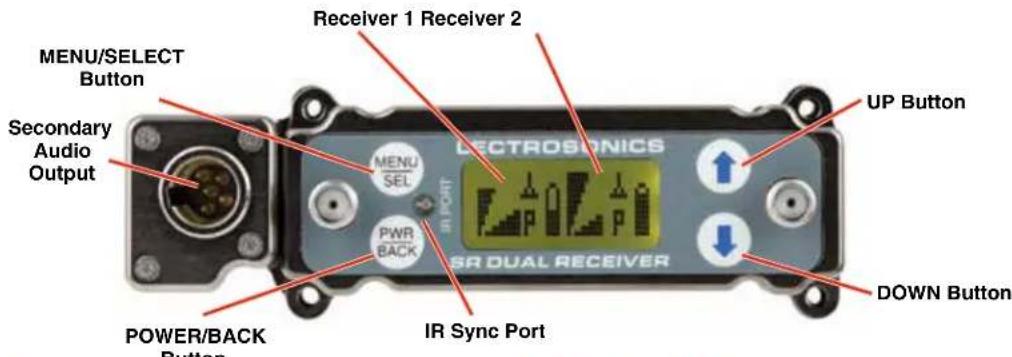
Audio Outputs
Audio outputs and the power inlet are located on the rear panel, accessed by a variety of different adapters. A second set of audio outputs is provided next to the front panel on the "5P" version for use with cameras that have only one audio channel enabled in the slot. One channel can feed the connector in the camera slot, and the second channel can be connected to the external audio jack on the camera with a cable. When the receiver is used outside of a camera, the 5-pin jack can be used to feed audio to a recorder, IFB transmitter or camera while the others feed the main production mixer. The front panel 5-pin connector (TA5M type) provides two balanced outputs with the following pinouts:
| Pin 1 Pin | 2 Pin 3 Pin | 4 Pin 5 | ||
| Shields | CH1 + CH1 | - CH2 + CH2 - |
LCD Screen
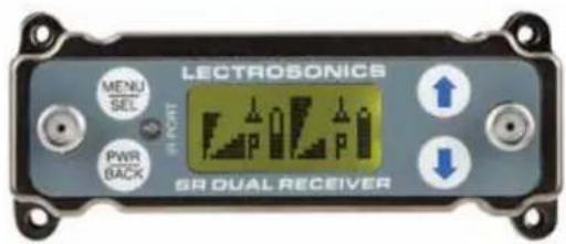
A backlit, graphics-type LCD is used to set up and monitor the receiver. The Main Window shown above is used during normal operation, to display RF and audio levels, transmitter battery status, pilot tone status and diversity activity for both receivers.
MENU/SELECT Button
This button is used to select menu items and enter setup screens during setup.
PWR/BACK Button
Press the PWR/BACK switch to turn the power on. Press and hold it until the display goes blank to turn power off. It also functions as a "back" button while navigating the various menus and setup screens to return to the previous screen or menu item.
The firmware “remembers” whether the receiver was turned on or off after power is disconnected, and it returns to that state when power is restored. This allows the receiver to power up and down as the external supply is turned on and off.
Press the PWR/BACK button from the Main Window to briefly display the external power voltage. Press it again to display the transmitter battery voltages. A third press returns to the Main Window.
IR (Infrared) Sync
An IR Sync Port is used for quick setup with transmitters that offer this feature. Settings for frequency, step size, compatibility mode and talk back are transferred from receiver to transmitter via the IR ports.
NOTE: Selected compatibility modes and talk back will only sync if they are available options on the transmitter you are syncing with.
UP/DOWN Arrow Buttons
The UP and DOWN arrow buttons are used to select various options and adjust values in the setup screens, and provide secondary functions such as locking out the panel to guard against accidental changes.
Rear Panel and Adapters
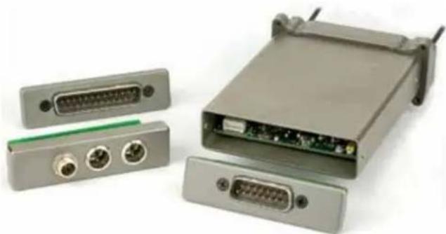
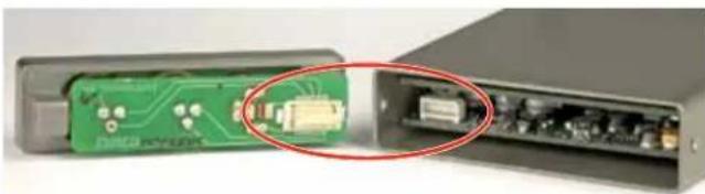
Several different panel adapters are available to configure the receiver for use with popular camera slots and for stand-alone use. The adapters are retained by two screws through the side panel of the housing, making them easy to install.
natural_image
Exterior view of a network device with multiple ports and connectors (no visible text or labels)Power and audio connections are made through mating connectors on the adapter and receiver circuit boards.
natural_image
Close-up of a green circuit board with an electronic component, showing internal wiring and a close-up view (no text or symbols visible)Camera Slot Adapters
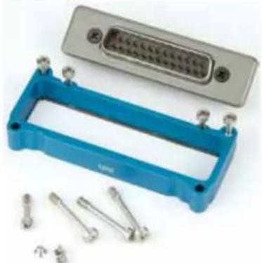
SRSUPER
natural_image
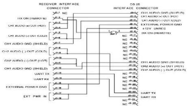
Electronic component housing with blue plastic casing and metallic connectors (no visible text or symbols)Adapter kit for Unislot® camera slots such as those provided on Ikegami® and Panasonic® cameras, as well as the SL-6 by Sound Devices®.* Includes bezel, hardware and rear panel DB25 connector wired for power and audio connections.
flowchart
graph TD
    A["RECEIVER INTERFACE CONNECTOR"] --> B["CH1 AUDIO GND (SHIELD)"]
    A --> C["CH2 AUDIO GND (SHIELD)"]
    A --> D["CH3 AUDIO GND (SHIELD)"]
    A --> E["UART TX"]
    A --> F["UART RX"]
    A --> G["EXTERNAL POWER GND"]
    A --> H["EXT PWR IN"]
    I["INTERFACE CONNECTOR"] --> J["CH1 AUDIO GND (SHIELD)"]
    I --> K["CH2 AUDIO GND (SHIELD)"]
    I --> L["CH3 AUDIO GND (SHIELD)"]
    I --> M["UART TX"]
    I --> N["UART RX"]
    O["DB 25 INTERFACE CONNECTOR"] --> P["CH1 AUDIO GND (SHIELD)"]
    O --> Q["CH2 AUDIO GND (SHIELD)"]
    O --> R["CH3 AUDIO GND (SHIELD)"]
    O --> S["CH4 AUDIO GND (SHIELD)"]
    O --> T["UART TX"]
    O --> U["UART RX"]
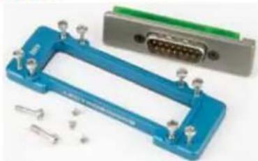
SRSNY
natural_image
Blue electronic device housing with multiple connectors and a gray connector block (no visible text or symbols)Adapter kit for Sony® camera slots, * includes bezel, hardware and rear panel DB15 connector wired for power and audio connections.
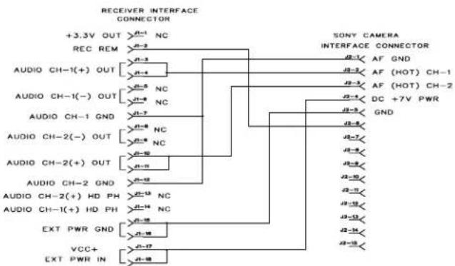
flowchart
graph TD
    A["+3.3V OUT"] --> B["REC REM"]
    B --> C["AUDIO CH-1(+) OUT"]
    B --> D["AUDIO CH-1(-) OUT"]
    B --> E["AUDIO CH-1 GND"]
    B --> F["AUDIO CH-2(-) OUT"]
    B --> G["AUDIO CH-2(+) OUT"]
    B --> H["AUDIO CH-2 GND"]
    B --> I["AUDIO CH-2(+) HD PH"]
    B --> J["AUDIO CH-1(+) HD PH"]
    B --> K["EXT PWR GND"]
    B --> L["VCC+ EXT PWR IN"]

    M["SONY CAMERA INTERFACE CONNECTOR"] --> N["AF GND"]
    M --> O["AF (HOT) CH-1"]
    M --> P["AF (HOT) CH-2"]
    M --> Q["DC +7V PWR"]
    M --> R["GND"]

    S["+3.3V OUT"] --> T["REC REM"]
    T --> U["AUDIO CH-1(+) OUT"]
    T --> V["AUDIO CH-1(-) OUT"]
    T --> W["AUDIO CH-1 GND"]
    T --> X["AUDIO CH-2(-) OUT"]
    T --> Y["AUDIO CH-2(+) OUT"]
    T --> Z["AUDIO CH-2 GND"]
    T --> AA["AUDIO CH-2(+) HD PH"]
    T --> AB["AUDIO CH-1(+) HD PH"]
    T --> AC["EXT PWR GND"]
    T --> AD["VCC+ EXT PWR IN"]
* UniSlot ^ is a trademark of Ikegami Tsushinki Co., Ltd. Ikegami ^ is a registered trademark of Ikegami Tsushinki Co., Ltd. Panasonic ^ is a registered trademark of Matsushita Electric Industrial Co., Ltd. Sony ^ is a registered trademark of Sony Kabushiki Kaisha TA Sony Corporation. Sound Devices ^ is a registered trademark of Sound Devices, LLC.
Installing Camera Slot Adapters
SRSUPER Adapter
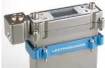
natural_image
Close-up of a metallic mechanical device with blue base and control buttons (no visible text or symbols)Thread two short screws through the recessed tabs on the adapter and slide it onto the receiver housing. Thread two short screws through the tabs on the receiver flange as shown.
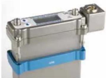
natural_image
Close-up of a metallic industrial device with blue base and mounting features (no visible text or symbols)On the opposite side, thread two long screws through the tabs on the receiver flange, then align them with the tabs on the adapter.
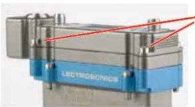
natural_image
Close-up of a mechanical device with blue and silver components and red laser lines (no readable text or symbols)Slide the adapter up and tighten the retaining screws to secure it to the receiver flange.
The four lower screws attach to the camera body.
SRSNY Adapter
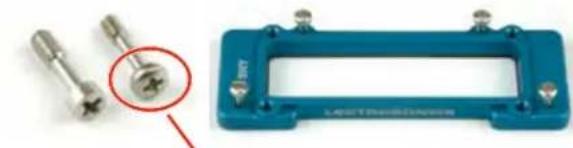
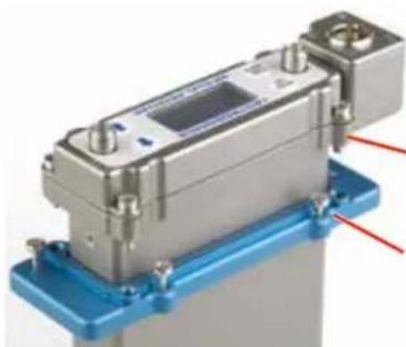
Two different types of screws are used to attach the receiver flange and the adapter.
natural_image
Close-up of two metallic screwdrivers and a blue industrial component with a red circle highlighting a small feature (no text or symbols visible)Thread the smaller, thin head screws through the adapter and into the camera body.
natural_image
Close-up of a metallic electronic component mounted on a blue base with red laser lines (no visible text or symbols)Upper screws with thicker heads secure the receiver to the adapter.
Lower screws with thinner heads secure the adapter to the camera body.
NOTE: If you are having difficulty inserting the receiver into the camera slot, try mounting the blue adapter plate to the camera first, then inserting the receiver.
Adapters for Stand-Alone Use
natural_image
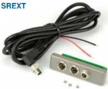
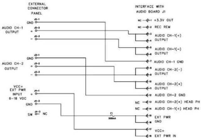
Coiled black cable with three connectors and a green connector, no visible text or symbolsFor stand-alone use, this kit includes a rear panel with two TA3 male jacks for the balanced outputs and a power jack with a locking connector. Trim the power cable to the desired length.
flowchart
graph TD
    A["EXTERNAL CONNECTOR PANEL"] --> B["GND"]
    A --> C["+"]
    A --> D["-"]
    E["AUDIO CH-1 OUTPUT"] --> F["GND"]
    E --> G["+"]
    E --> H["-"]
    I["AUDIO CH-2 OUTPUT"] --> J["GND"]
    I --> K["+"]
    I --> L["-"]
    M["VCC+ EXT PWR INPUT 6-18 VDC"] --> N["GND"]
    M --> O["+"]
    M --> P["SW"]
    Q["INTERFACE WITH AUDIO BOARD J1"] --> R["NC"]
    Q --> S["REC REM"]
    Q --> T["AUDIO CH-1(+) OUTPUT"]
    Q --> U["AUDIO CH-1(-) OUTPUT"]
    Q --> V["AUDIO CH-1 GND"]
    Q --> W["AUDIO CH-2(-) OUTPUT"]
    Q --> X["AUDIO CH-2(+) OUTPUT"]
    Q --> Y["AUDIO CH-2 GND"]
    Q --> Z["NC"]
    Q --> AA["ENC"]
    Q --> AB["EXT PWR GND"]
    Q --> AC["VCC+ EXT PWR IN"]
    AD["F1 900mA"] --> AE["900mA"]
SRHARNESS
Ideal for use in portable "bag systems." Two balanced output cables and the power cable are 6 feet long. Cut the cables to the desired length and terminate as needed.
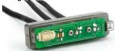
natural_image
Close-up of a green electronic device with visible circuit board and connectors (no text or symbols)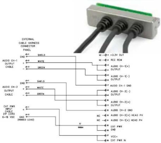
Installing Rear Panel Adapters
Installation of the rear panel output/power adapters is the same for all models.
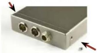
natural_image
Exterior view of a gray electronic device with two ports and red arrows indicating directional arrows (no text or symbols)Panels are held in place by two phillips head screws on the sides of the housing.
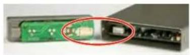
natural_image
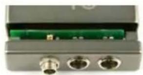
Close-up of a green circuit board with a red circle highlighting a component, next to an open black electronic device (no visible text or symbols)Connections between the panel and main circuit board are made via miniature mating connectors.
natural_image
Close-up of a gray electronic device with three ports and a green internal component (no visible text or symbols)Align the mating connectors and slide the panel straight into the housing until the screw holes align with the housing.
Replacement Screw Kits
natural_image
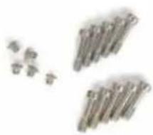
Abstract arrangement of metallic rods or rods with no visible text or symbolsSRSNYSCREWKIT
Contains:
5 - #28863 (smaller mid-length)
5 - #28864 (larger mid-length)
5 - #28869 (shortest)*
* For Housing

SRUNISCREWKIT
(also for SUPERSLOT)
Contains:
3 - #28862 (longest)
5 - #28864 (mid-length)
3 - #28869 (shortest)*
* For Housing
Battery Adapters
Battery sled adapters configure the receiver for standalone use or to provide battery backup power. Several options are available:
- SRBATTSLEDTOP
• SRBATTSLEDBOTTOM
• SR9VBP (inserts into the SLED adapters)
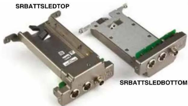
The battery sled adapters accept L and M type video camera rechargeable batteries and the optional SR9VBP 9 volt battery case.
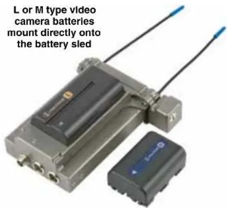
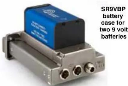
The battery sled adapters do not include charging circuitry. Batteries must be charged with their respective chargers. The adapters include an integral circuit that automatically selects between the battery and the external source, whichever delivers the highest voltage.
Installing the SRBATTSLED
Orient the battery sled so that the PCB connectors will mate when the sled is inserted.
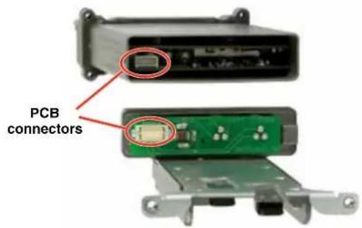
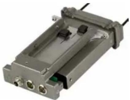
Slide the battery sled adapter into the end of the SR and gently seat it into place with the rear panel flush with the housing.
natural_image
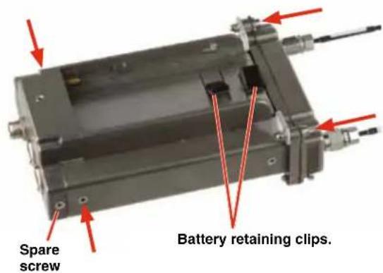
Exterior view of a gray industrial electronic device with ports and wiring (no visible text or symbols)Install and tighten the two side panel and two top panel screws as indicated by the arrows.
Battery Life
- The SR receiver operating time with a NP-F570 slim L series battery at full charge is approximately 12 hours.
- Battery life with two Energizer 9 volt alkaline batteries in the optional adapter is approximately 5 hours.
- Two LiPolymer 9 volt rechargeable batteries will operate the SR for approximately 6 hours. The operating time will typically decrease over the useful life of a rechargeable battery.
SR9VBP 9 Volt Battery Adapter
This optional adapter is mounted onto the battery sled for use as the primary power source or as a battery backup for an external power supply. The housing and door are constructed of machined aluminum.

natural_image
Three different energy storage batteries, one blue with 'LECTROBONCE MEVER' branding and two black variants (no visible text or symbols on the bases themselves)Slide the latch plate in the center of the door outward and swing the door open for access to two 9 volt battery compartments. Polarity barriers in each battery compartment protect against inserting the battery backwards. The circuitry is also protected electrically.
natural_image
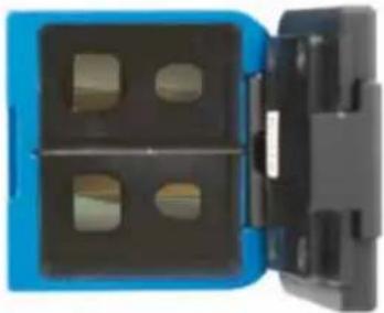
Close-up of a blue plastic connector with four square cutouts (no text or symbols visible)A pressure plate on the battery door compresses the battery contacts to maintain a solid connection with the batteries.
natural_image
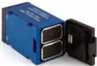
Blue and black electronic device casing with two internal components, no visible text or symbolsThe mechanical and electrical connections are the same as the rechargeable video camera batteries.
natural_image
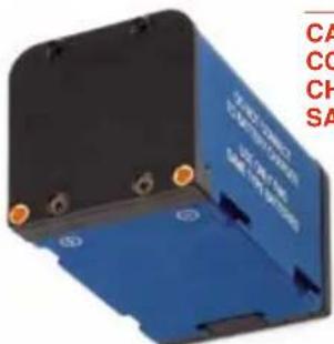
Blue electronic device with black components and orange connectors, no visible text or symbolsCAUTION: DO NOT CONNECT TO A BATTERY CHARGER. USE ONLY TWO SAME TYPE BATTERIES.
SRSLEEVE mounting adapter
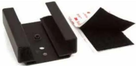
This sleeve is supplied with Velcro swatches for mounting an SR Series receiver on a flat surface of camera, cart, rack, etc. The sleeve is sized and lined for a snug fit in a vertical or horizontal position.
natural_image
Two black plastic components with cutouts and mounting holes, one partially filled with a red label (no visible text or symbols on the main objects)SRHARDWARE mounting adapter kit
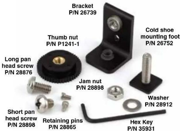
For a vertical mounting, attach the right angle bracket to the bottom of the sleeve.
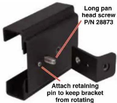
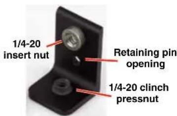
The bracket provides two different mounting nuts. The standard pressnut is used to attach the sleeve. The tensioning (clinch type) pressnut is used to attach the cold shoe mounting foot.
Attach the bracket to the sleeve with the long pan head screw into the standard pressnut. The retaining pin fits into the opening in the bracket. Attach the cold shoe mounting foot to the tensioning nut and rotate it to orient the receiver as desired.
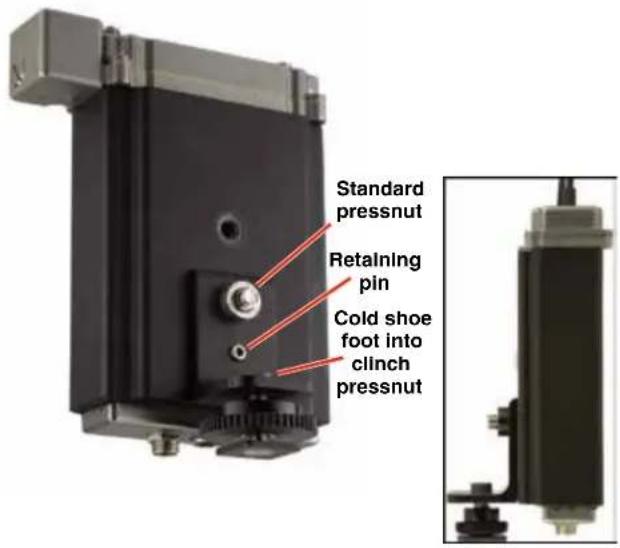
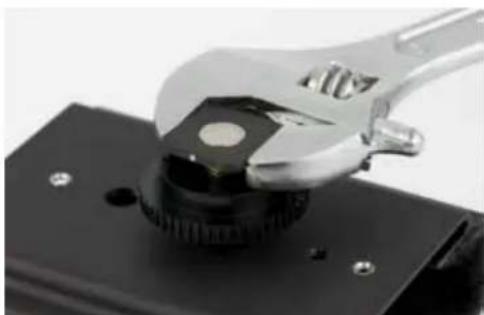
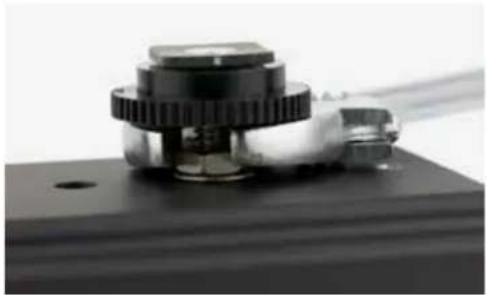
The clinch nuts in the foot and housing apply friction to the threads to allow the foot to be rotated to the desired position, with the jam nut locking it in place. Use a wrench to rotate the foot, then tighten the jam nut to prevent the foot from rotating.
Clinch pressnut in bracket and sleeve
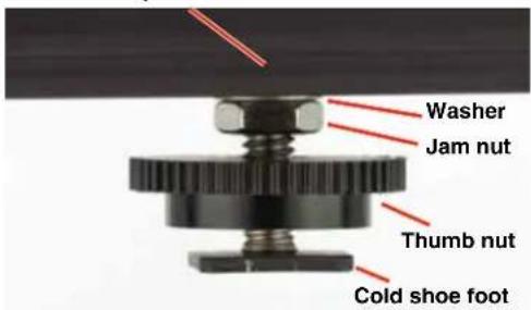
For horizontal mounting, insert the cold shoe foot into the clinch nut in the sleeve. Rotate the foot to the desired postion, then tighten the jam nut to lock it in place.
natural_image
Close-up of a wrench gripping a mechanical component with a central knob (no text or symbols visible)Use a wrench to thread the stud in about 1 - 2 turns, then rotate it to orient the receiver control panel in the desired direction.
natural_image
Close-up of a mechanical component with gears and a transparent tube, no visible text or symbolsTighten the jam nut to prevent the foot from rotating
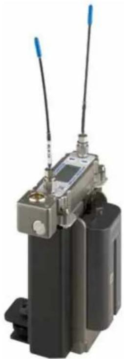
Used together, the battery sled, sleeve and mounting foot create a versatile, stand-alone, self-powered configuration for an SR Series receiver.
natural_image
Exterior view of a black industrial device with two antennas and a display unit (no visible text or symbols)Audio Output Cables and Connectors
MCSR5PXLR5P
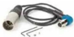
Right angle TA5F plug to 5-pin XLR; balanced outputs; 25 inches long. For TA5M output jacks.
MCSR5PXLR2

Right angle TA5F plug to two 3-pin XLR; balanced outputs; 20 inches long. For TA5M output jacks.
MCSRPT
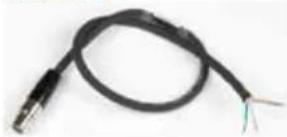
natural_image
Coiled black cable with two wires, no visible text or symbols12 inch long TA3 female to stripped and tinned wires for balanced output.
PIN 1: Shield
PIN 2: Audio (+) white
PIN 3: Audio (-) green
MCSRXLR
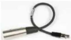
12 inch long TA3 female to XLR male 3-pin for balanced output.
PIN 1: Shield
PIN 2: Audio (+)
PIN 3: Audio (-)
MCSRTRS
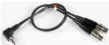
natural_image
Coiled black cable with three metallic connectors (no text or symbols visible)Male 3.5 mm TRS plug to two female TA3 (mini XLR) connectors for dual channel use.
RATPAC Adapter Kit
natural_image
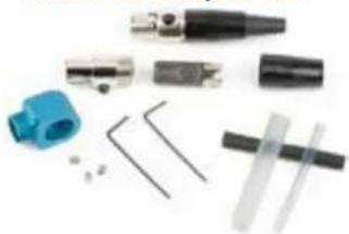
Collection of mechanical components and tools laid out on a white background (no visible text or symbols)Adapter kit to build either a 3-pin or 5-pin TA Series right angle connector. Includes standard 5-pin connector, modified 3-pin insert and backshell, aluminum right angle housing, strain relief tubing, set screws and wrenches.
The 5-pin RATPAC right angle connector is designed for the front panel output jack. The 3-pin version is designed for the rear panel outputs on the receiver.
natural_image
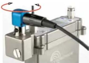
Close-up of a mechanical device with a blue component and black cable, no visible text or symbolsThe connector can be rotated during assembly to exit the cable in the desired direction. See instructions included with the RATPAC kit.
External Power Supply
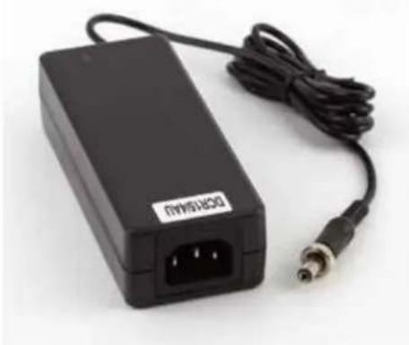
DCR15/4AU
Power supply with a standard C14 inlet and locking LZR coaxial output connector; 100-240 VAC in, 15 VDC regulated output; 4A max.
natural_image
Black electronic device with attached cable and connector (no visible text or symbols)External Power Cables
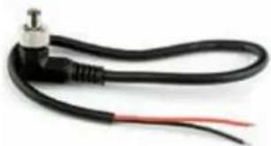
21747
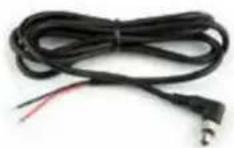
Locking LZR style plug to stripped and tinned; 6 feet long.
2174 6
natural_image
Coiled black cable with a metallic connector and red wire, no visible text or symbolsLocking LZR style plug to stripped and tinned; 12 inches long.
PS200
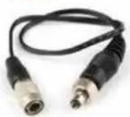
Hirose 7-4 pin to LZR type locking plug, 12" long.
21425
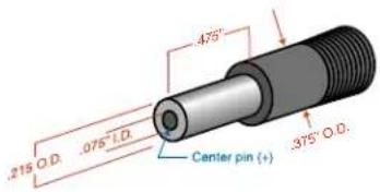
6 ft. long power cord; coaxial to stripped & tinned leads. Coaxial plug: ID-.080"; OD-.218"; Depth-.5".
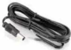
21472
6 ft. long power cord; coaxial to stripped & tinned leads. Right angle coaxial plug: ID-.075"; OD-.218"; Depth-.375"
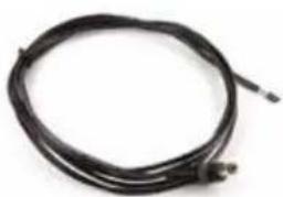
natural_image
Coiled black cable with a small connector at the end (no text or symbols visible)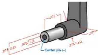
21586
DC16A Pigtail power cable, LZR stripped & tinned. Thread lock collar.
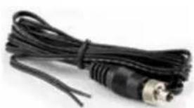
natural_image
Coiled black cable with metallic connector (no text or symbols visible)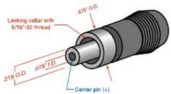
Mounting and Orientation
A variety of accessories are available to enable various mounting options. For maximum operating range, the antennas should be vertical and above the camera and other equipment. The AMJ Rev. A antenna is jointed so the whips can be oriented vertically.
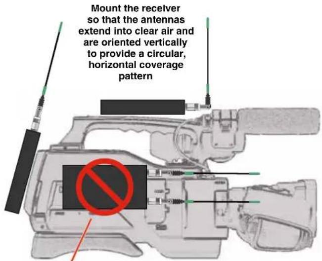
Do not mount the receiver so the antennas will be next to another piece of equipment nor oriented horizontally

natural_image
Exterior view of a black industrial electronic device with two antennas and a display unit (no visible text or symbols)The receiver provides stand-alone operation with the battery sled adapter and mounting sleeve. It can be mounted in any position with Velcro, or in horizontal and vertical positions using the mounting foot, or mounted directly onto a 1/4-20 threaded stud on a tripod.
The diagrams below depict typical orientations of transmitter and receiver antennas in field production and how the RF signal transfer is affected. Maximum sensitivity is perpendicular to the whip, so an ideal setup is shown in Fig. 1 and Fig. 2 where the receiver is mounted in either a vertical or horizontal position with the whips oriented vertically.
Fig. 3 depicts the receiver and antenna whips oriented horizontally, which places the null of the receiver antenna pattern pointing toward the transmitter. The result, of course, is a weak signal entering the receiver.
Fig. 4 depicts the worst setup where the nulls in both receiver and transmitter patterns face one another.
The transmitter antenna whips can point upward as shown in these diagrams, but they will work just as well with the whip pointing downward. Mount the transmitter so that the whip is vertical and not in direct contact with the wearer's body or metallic objects in clothing and costuming.
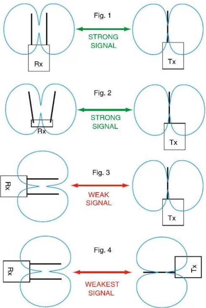
flowchart
graph TD
    A["Rx"] -->|Strong Signal| B["Tx"]
    C["Rx"] -->|Strong Signal| D["Tx"]
    E["Tx"] -->|Weak Signal| F["Tx"]
    G["Rx"] -->|Weak Signal| H["Tx"]
    I["Tx"] -->|Weakest Signal| J["Tx"]
AMJ Rev. A Jointed Antenna
The AMJ antenna is a general purpose design for any Lectrosonics receiver or transmitter with a standard SMA connector. The hinged joint pivots in both directions for positioning the whip at any desired angle.
AMJ KIT CUTTING TEMPLATE
Lay uncut antenna on this template and cut to length for the desired frequency block

Trim the end of the color cap and slide the remaining sleeve over the whip - OR - Glue color cap onto the end
Note: Check the scale of your printout. This line should be 6.00 inches long (152.4 mm).
natural_image
Close-up of metallic coaxial connectors with black cables, no visible text or symbolsThe hinged joint pivots in both directions
LCD Main Window
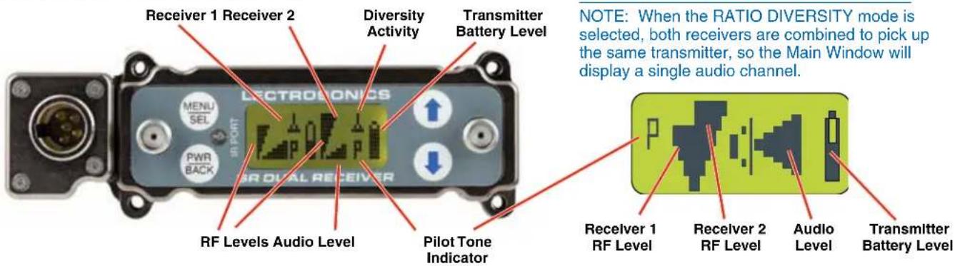
The Main Window displays information concerning the condition of the Pilot Tone, antenna phase, RF and audio signal levels and battery conditions for both the receiver and the associated transmitter.
Pressing the MENU/SEL button accesses the menus and screens for setting up the receiver and searching for clear frequency channels.
| Icon | Description |
| Pilot Tone IndicatorA steady “P” icon will be displayed when a pilot tone from the transmitter is present. The “P” will appear only in those compatibility modes which use pilot tone, such as the native Digital Hybrid, 200 Series, IFB modes and Mode 6. The icon will flash if no pilot tone is detected and will change to a small “b” if the pilot tone has been bypassed. To bypass or enable the pilot tone on Receiver 1, hold MENU/SEL button and press the UP button briefly. To bypass or enable the pilot tone on Receiver 2, hold MENU/SEL and press the DOWN button briefly. Bypassing the pilot tone also disables the squelch, regardless of which compatibility mode has been selected.Channel MuteThe audio output can be muted on Receiver 1 by holding the MENU/SEL button and holding the UP button for about a second or more. Receiver 2 can be muted by holding MENU/SEL and then holding the DOWN button. The same buttons toggle the mute status off. An “M” will appear on the screen when a channel is muted. In ratio diversity mode, the UP button is used and a signal M appears.Antenna Phase IndicatorThis antenna icon is displayed when the SWITCHING DIVERSITY mode is selected. As the antenna phase is switched, the symbol will flip vertically.RF LevelThis icon changes in size vertically to indicate the strength of the incoming RF signal.Audio LevelsOne icon is used in the SWITCHED DIVERSITY mode and the other when RATIO DIVERSITY is selected. The icon changes in size horizontally to indicate the audio level (modulation) of the signal received from the transmitter. The icon display will change to a solid rectangular block when the audio signal is being limited in the transmitter.Battery LevelsWhen the COMPAT mode is set for a compatibility mode that supports battery telemetry (Digital Hybrid and 200 Series), a battery icon is displayed on the LCD to indicate the transmitter battery condition. The receiver will periodically check the battery voltage and update the icon in a “fuel gauge” manner. In the example at left, the icon indicates about “half full.” When other COMPAT modes are selected, this area of the LCD will be blank.If selected in the TXBAT setup screen, a transmitter battery timer is available for any compatibility mode. It accumulates hours and minutes whenever the transmitter is turned on, and retains the accumulated time even when the receiver is off. The icon represents a digital clock readout (rotated 90 degrees clockwise) and in this example is indicating 4 minutes.To reset the battery timer, change the selection in TXBAT to something other than a timer mode, then back to the desired mode. |
Main Window
The appearance of the LCD Main Window will change according to which diversity mode is selected:
- SWITCH (2-channel mode) splits the screen to indicate activity and levels on both receivers and transmitters.
- RATIO combines the audio outputs of both receivers to deliver a single audio channel.
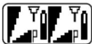
With the DIV MODE set to SWITCH, two audio channels will be displayed.
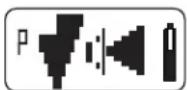
With the DIV MODE set to RATIO, a single audio channel will be displayed.
Frequency Screen
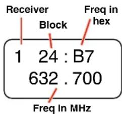
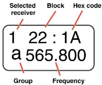
Press MENU/SEL from the Main Window once for Receiver 1 and twice for Receiver 2. The selected receiver is shown in the upper left corner of the LCD.
In this example, the upper screen denotes that receiver 1 is set at 632.700 MHz, requiring
that any transmitter with hex switches be set at B7 for this frequency. Lectrosonics transmitters with LCD interfaces allow frequency to be set in MHz or hex settings.
Press the UP and DOWN buttons to change the frequency of the receiver. When the tuning mode is set to NORMAL, the UP and DOWN buttons tune in single channel increments. In the group tuning modes, the UP and DOWN buttons step through the frequencies stored in the particular group. Refer to the menu item named TUNING for details.
Setup Screens
From the Main Window, press MENU/SEL three times to enter the setup screens. Press UP and/or DOWN to scroll through the available items and press MENU/SEL to enter the desired screen. For those items that allow separate settings for each receiver, press MENU/SEL repeatedly to toggle back and forth between Receiver 1 and Receiver 2, then press the UP and DOWN buttons to select the value or option, then press BACK to return to the previous screen.
SHORTCUT: Hold the MENU/SEL button in while pressing the UP or DOWN arrow to jump in 16 channel increments (1.6 MHz steps).
Locking and Unlocking the Front Panel Controls
The front panel controls can be LOCKED to prevent accidental changes being made during operation and handling.
Note: Whether locked or unlocked, the setting persists when the unit is off and even when the power is turned off.
From the Main Window, press and hold the UP and DOWN arrows at the same time and observe the display. The current state is displayed as LOCKED or UNLOCKED, and numerals appear as a 3, 2, 1 countdown takes place. When the countdown is complete the state is reversed and the new state is displayed.
LCD Backlight Setup
With the power on, simultaneously press the UP button AND the POWER/BACK button. The unit will then display the Backlight Options screen. Use the UP and DOWN arrows to select the desired backlight operating mode.
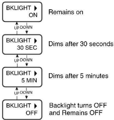
flowchart
graph TD
    A["BKLIGHT ON"] --> B["Up DOWN"]
    B --> C["BKLIGHT 30 SEC"]
    C --> D["Up DOWN"]
    D --> E["BKLIGHT 5 MIN"]
    E --> F["Up DOWN"]
    F --> G["BKLIGHT OFF"]

    note1["Remains on"]
    note2["Dims after 30 seconds"]
    note3["Dims after 5 minutes"]
    note4["Backlight turns OFF and Remains OFF"]
Battery Timer Reset
Navigate to TXBAT in the menus and select anything other than AAT, 9VT or LBT. Then set it back to the timer setting that matches the batteries you are using in the transmitter. There is no need to exit the setup screen. The timer will be reset when you select a non-timer mode.
Navigating the LCD
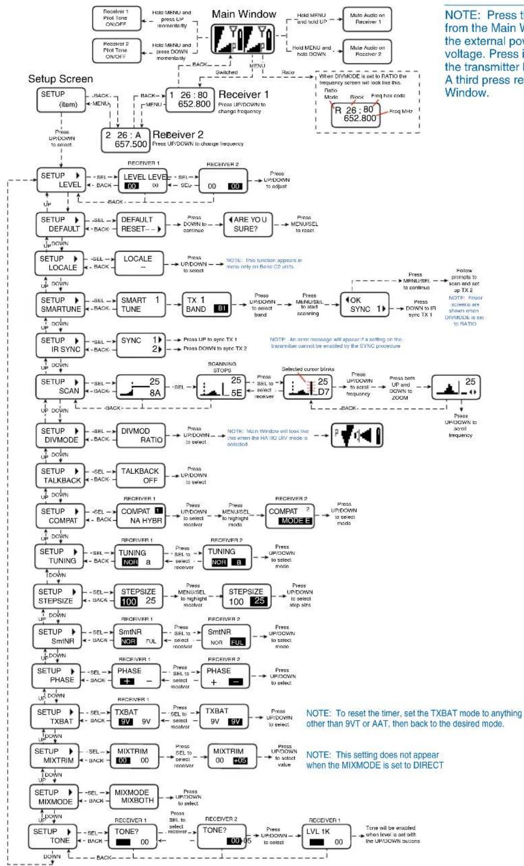
flowchart
Audio system control flowchart for a three-phase reverse window, showing setup screen, level/level conversion, and output modes with key parameters like up/down, downdown, and timing constraints.NOTE: Press the BACK button from the Main Window to display the external power supply voltage. Press it again to display the transmitter battery voltages. A third press returns to the Main Window.
Menu Item Descriptions
LEVEL
This setup screen displays the audio output level of the receiver in dBu when the transmitter is fully modulated. Press the MENU/SEL button to toggle between receiver 1 and receiver 2. Use the UP or DOWN buttons to change the level. Range is from -50 to +5 dBu in 1 dB steps. Press the BACK button to leave this screen.
The output levels at the two jacks may be set independently, regardless of the diversity mode setting.
DEFAULT
Restores the factory default settings.
LOCALE (Band C2 units only)
The LOCALE setup screen has two settings, “--” and “JA”. If “JA” is selected, C2 band coverage stops at 713.9 MHz. If “--” is selected, C2 band coverage goes all the way to 716.775 MHz.
SMARTUNE
See the section entitled Finding Clear Frequencies with SmartTune™.
IR SYNC
Navigate to this menu item to manually initiate the IR sync transfer. Hold the IR ports on the transmitter and receiver facing each other a foot or two apart and press the UP arrow for channel 1 or the DOWN arrow for channel 2. Watch for a confirmation on the transmitter LCD to verify the settings were correctly transferred. If one or both settings could not be enabled on the transmitter, an error message will appear on its screen.
SCAN
See the section entitled Finding Clear Frequencies with Manual Scanning.
DIVMODE
The SWITCH diversity mode (dual channel mode) allows the two internal receivers to operate independently on different frequencies and settings with two different transmitters. Diversity reception uses an antenna phase switching technique on each receiver. When this mode is selected, the setup screens will prompt you to select the receiver to be adjusted.
The RATIO mode combines the two internal receivers to pick up the same transmitter and mix their audio outputs in a ratio panning mode. In this mode, the setup screen for frequency will prompt you for a single value which will automatically be set for both receivers.
TALKBACK
This is a special function that re-directs the audio output of the transmitter in use to the channel 2 output when a button is pressed on the transmitter. The normal use is to provide a "com" channel so the person using the transmitter can have a direct line to the crew or production staff that is not sent to the program output. The HHa hand held transmitter provides a programmable switch on the housing that can be configured for this function.
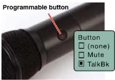
As long as the button is held in, the audio will appear at the channel 2 output. When the button is released, the audio output will switch back to channel 1.
To enable this mode, simply select Talk-
back in the menu and use the UP and DOWN arrow buttons to turn the function on. The mode must also be enabled on the transmitter.
Talkback works the same way in either the SWITCHED or RATIO diversity modes, but ONLY works in the HYBRID compatibility modes.
NOTE: When Talkback is enabled, only receiver 1 and a blinking TB will appear in the Main Window.
COMPAT
Compatibility modes adjust the FM deviation and audio processing (companding) to match other Lectrosonics models and some models from other manufacturers.
| NA HYBR North American Digital Hybrid Wireless ^ |
| NU HYBR ETSI compliant Nu Digital Hybrid Wireless® |
| MODE 3 Other manufacturer* |
| 200 SER 200 Series transmitters |
| 100 SER 100 Series transmitters |
| JA MODE3 Japan Other manufacturer* |
| JA HYBR Japan Digital Hybrid Wireless ^ |
| MODE E Other manufacturer* |
| EU HYBR European Digital Hybrid Wireless ^ |
| 300 SER 300 Series transmitters (European) |
| MODE 7 Other manufacturer* |
| MODE 6 Other manufacturer* |
| IFB SER Standard IFB mode |
NOTE: Make certain the COMPAT mode is set to match the mode in the transmitter for optimum audio quality. If the modes are not matched, the audio will be distorted or noisy, or there may be no audio at all.
TUNING
In addition to the NOR (normal) mode, this screen also allows Selection of one of four factory pre-selected frequency groups (Groups a through d) or two user programmable frequency groups (Groups u and v).
- NOR allows selection of all 256 frequencies that the receiver will tune. Each press of the UP or DOWN button will step in 100 kHz increments to the next frequency.
- a, b, c, d sets the receiver to tune only factory preselected frequencies, up to eight in each group. Each press of the UP or DOWN button will step to the next frequency in the group. (see page 26)
- u, v allow up to 16 user-selected frequencies to be stored in each group. Each press of the UP or DOWN button will step to the next stored frequency in the group.
Note: The TUNING setup screen only selects the tuning mode (NORMAL or Group Tuning). Operating frequencies are chosen through the Frequency Screens.
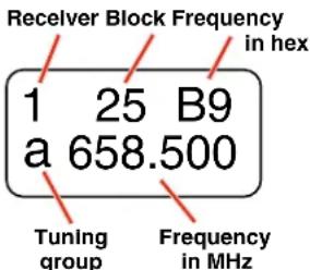
When any tuning mode other than NOR is selected, the frequency screen will include the selected tuning group number.
If the selected frequency is not in the tuning group, the tuning group indicator will blink.
1 25 B9 a 658.500
NOTE: When a tuning group is selected, the available frequency selections will be limited to those that are in the tuning group.
In compatibility modes other than Digital Hybrid and 200 Series, no battery telemetry information is available, so the TXBAT setup screen offers only two choices:
- --- (no timer) - Display no transmitter battery status in the main window.
- TIM - Monitor the transmitter battery status with the battery timer in the LCD Main Window.
NOTE: To reset the timer, set the TXBAT mode to anything other than AAT, 9VT or LBT, then back to the desired mode.
USING THE GROUP TUNING MODES
Press MENU to select receiver 1 or 2 and view the frequency screen. Press the UP or DOWN button to switch to the next frequency in the group.
1.470:1A a472.700
A letter will appear next to the frequency to indicate which group is selected.
Holding the MENU/SEL button while pressing the UP or DOWN button will step to the next frequency in either 25 or 100 kHz steps, which will select a frequency that is not stored in the group. In this case, the group letter in the display will blink to indicate that the selected frequency is not included in the group.
The letter will blink when a frequency outside of the tuning group is selected.
About using groups u and v:
When no frequencies are stored in groups u and v, the UP and DOWN buttons will function the same as the NORMAL mode (each press up or down one step).
When only one frequency is stored in group u or v, hold the MENU/SEL button in and then press the UP or DOWN button to scroll to a different frequency.
Adding/Deleting frequencies to groups u and v:
Select the frequency and then do one of the following:
- Starting with firmware v1.15, simply press and hold the MENU button until the u or v stops or starts blinking.
- With earlier firmware versions, hold the MENU button in and then press and hold the UP or DOWN arrow button until the u or v starts or stops blinking.
STEPSIZE
Selects the frequency increment on each receiver to 25 kHz or 100 kHz.
SmtNR
This setup screen is available only in the Digital Hybrid COMPAT (compatibility) mode. Select the desired mode while listening to the audio to of one of three choices:
- OFF provides no noise reduction for complete transparency, which is useful in controlled environments with very little high frequency noise such as an indoor motion picture production set.
- NORMAL applies a moderate amount of noise reduction to noticeably reduce hiss from subtle sources such as electret microphones.
- FULL is very similar to the Lectrosonics noise reduction system used for many years in the 195 and 200 Series analog systems. Hiss from electret microphones and some environmental HF noise are suppressed.
PHASE
This setup screen allows the audio output polarity to be inverted to match other microphones or audio sources.
TXBAT
- AA - Transmitter uses a AA alkaline battery.
- AAL - Transmitter uses a AA lithium battery (not rechargeable).
- AAT - Transmitter uses an alkaline, lithium or rechargeable AA battery. Monitor the battery status with the timer in the receiver.
- LB - Transmitter uses a Lectrosonics LB-50 rechargeable battery.
- LBT - Transmitter uses a Lectrosonics LB-50 rechargeable battery.
- 9V - Transmitter uses a 9V alkaline battery.
- 9VL - Transmitter uses a 9V lithium battery (not rechargeable).
- 9VT - Transmitter uses a 9V battery of any type. Monitor its status with the timer in the LCD Main Window.
MIXTRIM and MIXMODE
When set to the SWITCHED (dual channel mode), special options are available to allow the audio from the receivers to be mixed to either one or both audio output channels.
The MIXMODE setting determines which audio signal appears at which output channel:
- MIXBOTH mixes the audio and delivers the mix to both output channels.
- MIXTO 1 mixes the audio and delivers the mix to output channel 1.
- MIXTO 2 mixes the audio and delivers the mix to output channel 2.
- DIRECT keeps the audio separated and delivers receiver 1 audio to output channel 1, and receiver 2 audio to output channel 2.
The MIXTRIM setting applies attenuation up to 20dB in 1 dB steps to adjust the ratio of the two audio signals in the mix. This adjustment takes effect only when a mix mode is selected (it is ignored when the mix mode is set to DIRECT).
IMPORTANT: The output level of each receiver is adjusted with the LEVEL setup screen, which is hardware-based, so it affects the output level regardless of which mix mode is selected. MIXTRIM then applies attenuation to that level setting resulting in the final level delivered to the output channel. It is good practice to set the output level of both receivers to the same value when using a mix mode.
When a MIXMODE is selected, each audio signal is automatically attenuated by 6 dB prior to the mixing. This is done to avoid overload and potential distortion since mixing increases the level by 6 dB.
TONE
The TONE setup screen enables an audio test tone at the receiver output for precise level matching with other equipment. The first screen prompts you to press the UP or DOWN button to enable the tone at the receiver output. Press MENU/SEL to toggle between receivers.
RECEIVER 2
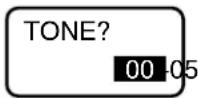
The first screen prompts you to press the UP or DOWN button to start the tone.
Once the button is pressed, a 1 kHz tone is enabled, and its level can be adjusted with additional presses on the UP or DOWN buttons.
The level set here will be retained in the regular operating mode. It will supersede the setting made in the LEVEL setup screen. The test tone has 1% distortion and is intended for confirmation of output levels only. To exit the test tone screen and stop the tone press the BACK button.
Front Panel Shortcuts
A convenient shortcut is available from any setup screen that displays the two receiver selection options next to each other, such as the LEVELS and STEPSIZE screens. Once the value has been set on one receiver, the same value can be copied to the other receiver with a simple button push combination.
Hold the MENU/SEL button and press the DOWN arrow to copy the value set on receiver 1 to receiver 2. Hold MENU/SEL and press UP to copy the value set on receiver 2 to receiver 1.

flowchart
graph LR
    A["LEVEL LEVEL +05 00 00"] --> B["Hold MENU and press UP arrow"]
    B --> C["00"]
NOTE: It does not matter which receiver is selected (highlighted).
Accessing Block 606
Band B1, B2 and C1 SRc receivers can be used with legacy Block 606 Lectrosonics transmitters by invoking a special Block 606 legacy mode so the correct pilot tones will be present. To invoke the Block 606 mode, press the BACK button as needed to move to the Main Window, then press the PWR/BACK and DOWN arrow buttons simultaneously. Use the UP and DOWN arrows buttons to select the desired tuning range.
Beginning with firmware v1.13, the LCD will simply display 606 on the setup screen. Previous firmware versions display 606B or 606C if you are a using Band B1 or C1 unit. When the mode is enabled, 606 will appear in the frequency selection screen as a reminder that the mode is enabled.
Finding Clear Frequencies with SmartTune™
SmartTune is the easiest and fastest way to scan the local RF spectrum and find clear operating frequencies.
The receiver will scan through its tuning bandwidth and automatically find “empty” areas within the tuning range that have little or no RF energy. The receiver will then be set to a frequency within an empty area and prompt you to continue or use the IR function to sync to a transmitter.
Note: Pressing BACK during an active scan will restore the operating frequency to what it was set at pre-scan.
When the DIVMODE is set to SWITCHED, there are two different frequencies that can be discovered, so the LCD screens will prompt you through the procedure for one receiver, then continue to repeat the process for the other receiver. When the DIVMODE is set to RATIO, there is only one frequency to be found.
The sample screens shown here are for the SWITCHED mode. Similar screens appear for the RATIO mode, but there is only one frequency to be discovered.
SETUP SMARTUNE
Navigate to the SMARTUNE screen and press MENU/SEL.
SMART TUNE
1
Use the UP and DOWN arrows to select receiver 1 or 2, and press MENU/SEL.
TX 1 BAND
B1
The scan can cover all three blocks in the band, or only one of the three. Use the UP and DOWN arrows to select the tuning range to be scanned:
B1 - the entire Band B1
21 - block 21 only
22 - block 22 only
23 - block 23 including TV37
23N - block 23 bypassing TV37*
B1N - Band B1 bypassing TV37*
*NOTE: 23N and B1N ("N" refers to North America) scans skip past TV Channel 37 (608 to 614 MHz) since it is reserved for radio astronomy in North America.
OK SYNC
1▶
After the scanning is complete, the newly discovered frequency will be set automatically. The LCD will then prompt to SYNC the frequency to the matching transmitter via the IR port (DOWN ARROW), or to continue by pressing OK (MENU/SEL).
TUNE RX2 NOW? YES
After leaving the SYNC screen, the LCD will ask about setting up the other receiver. Use the UP and DOWN arrows to select YES to tune the other receiver, then press MENU/SEL to continue.
IS TX1 ON?
YES
Turn on the transmitter that matches the first receiver that was tuned. Use the UP and DOWN arrows to select YES and press MENU/SEL.
OK SYNC
2
After the scanning is complete, the newly discovered frequency will be set automatically. The LCD will then prompt to SYNC the frequency to the matching transmitter via the IR port (DOWN ARROW), or to continue by pressing OK (MENU/SEL).
RF signal strength

Pilot Tone Icons (P)
Press the BACK button several times to return to the Main Screen and verify that both transmitters show a strong RF signal strength and that the Pilot Tone icons are NOT blinking (when Pilot Tone is enabled).
It is always good practice to verify the frequencies by going through the procedure in the section entitled Multi-channel System Checkout.
Finding Clear Frequencies with Manual Scanning
Scan Window
flowchart
graph TD
    A["Receiver 1, dashed line"] --> B["RF activity level"]
    C["Receiver 2, solid line"] --> D["Freq in hex"]
    E["Block"] --> F["26"]
    G["BS"] --> H["Freq in hex"]
    I["Cursor (center bar)"] --> J["Cursor (25)"]
    K["FS"] --> L["Freq in hex"]
    M["Press both UP and DOWN arrows on control panel to switch to the Zoom View"] --> N["↓"]
    O["Press the BACK button to return to the Scan View Window"] --> P["↓"]
    Q["↑"] --> R["↓"]
    S["↓"] --> T["→"]
First, turn off all of the transmitters you intend to use with the receiver.
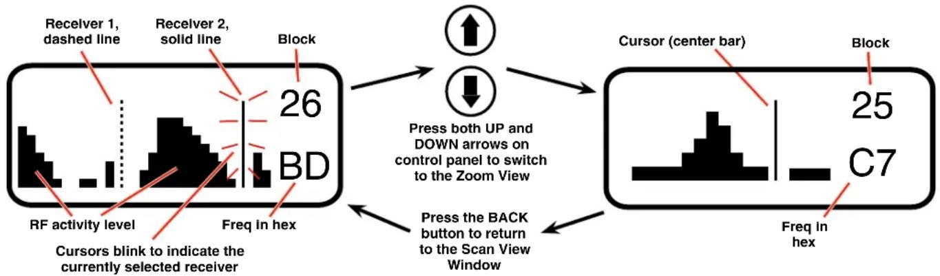
Navigate to the SETUP>SCAN screen and press the MENU/SEL button to start the scanner. The display will switch to the Scan Window (see illustration above) and start scanning immediately. Allow the receiver to scan across the entire tuning range at least once, then press the MENU/SEL button to stop the scanning.
When the receiver is configured for SWITCHED diversity (dual channel mode), two cursors will appear when the scanning is stopped. The cursor for receiver 1 is a dashed line and the cursor for receiver 2 is a solid line. Press MENU/SEL to toggle between the two receivers (selected channel will blink). Select the channel and use the UP and DOWN buttons to move the cursor and locate a frequency with no (or very weak) RF activity.
Scroll through the screen with the UP and DOWN buttons and find a frequency where no RF signals (or in the worst case, only very weak RF signals) are present. Press the PWR/BACK button to set the receiver to this new frequency.
Press both the UP and DOWN buttons at the same time to switch to the Zoom View Window (see illustration above). In this view, the cursor remains fixed in the center of the screen and the background scrolls behind it. The frequency can be stepped up and down in 100 kHz increments using the UP and DOWN arrow buttons.
Zoom View Window

Keep the frequencies of the two receivers at least 700 kHz apart to minimize de-sensing (short range) issues. This spacing is a “worst case” approximation assuming the transmitters are about 25 feet from the receiver antennas.
IMPORTANT:
FREQ. WARNING
Performance will be degraded if Receiver 2 is set 4.2 to 4.8 MHz higher than Receiver 1. The LCD will also flash this message periodically.
Data gathered during a scan is stored until it is intentionally erased or the power is turned off. Previous data will remain and subsequent scans can be made to search for additional signals or to accumulate higher peaks.
To clear the scan memory and screens, press and hold the PWR/BACK button briefly. As soon as Powering off... appears on the display, release the button. The receiver will remain turned on, and the scan data will be erased.
Set your transmitter/s to match the corresponding receiver/s (CH1 or CH2) on the receiver display. Turn the transmitter on and verify that a strong RF signal is present. If your transmitter has an IR (infrared) port, you can transfer the frequency setting using the IR interface.
It is always good practice to verify the frequencies by going through the procedure in the section entitled Multi-channel System Checkout.
Pre-coordinated Frequencies
NOTE: As the spectrum has become more congested, interference from external sources has become common. As a result, the frequencies provided in these pre-coordinated groups may or may not be 100% usable in some locations. Interference from external sources may appear as direct signals, or may mix with the pre-coordinated frequencies and generate new RF signals through IM (intermodulation).
About Frequency Coordination
Interference from IM (intermodulation) is a potential problem in all multi-channel wireless systems, so proper frequency coordination is always required to avoid noise, range and dropout problems. Your options to accomplish this include:
• Using the pre-coordinated frequency groups
- Scanning with the receiver and performing a system checkout (See Multi-channel System Checkout)
- Contacting Lectrosonics for assistance
Groupings of compatible frequencies have been created to minimize intermodulation problems in multiple channel wireless systems. The frequencies can be used with Digital Hybrid and analog Lectrosonics wireless equipment. Compatibility with other brands is likely, but not guaranteed by Lectrosonics.
These frequencies have been calculated to minimize IM between these frequencies only, however, RF signals from outside sources can still interfere with operation. So, even if only these pre-coordinated frequencies are being used, a Multi-channel System Checkout should be conducted. See the procedure on the next page.
The eight frequencies in each of the four groups are generally compatible for simultaneous use.
Special Notes on Block 23
The block 23 frequency range includes the spectrum from 608 through 614 MHz that is allocated for radio astronomy (radio telescopes) which is blocked from use in the US. The SRc Series receivers are tested and compliant with the technical standards in the US and Europe, so frequencies can be selected in the 608 to 614 MHz range. US model transmitters, on the other hand, will not tune to frequencies in this range.
European model transmitters, which include "E01" in the model number, will operate within the 608 to 614 MHz band. Be certain that the COMPAT (compatibility) mode is set to match the transmitter model and COMPAT mode.
Pre-coordinated frequencies are arranged in four groups as shown in this example of block 22.
The receiver LCD displays the current settings.
| FREQ SW SET US TV CH | ||
| 563.700 0 | 5 | t/29 |
| 564.300 0 | B | t/29 |
| 565.200 1 | 4 | t/29 |
| 565.800 1 | A | t/29 |
| 567.100 2 | 7 | t/30 |
| 568.000 3 | 0 | t/30 |
| 568.500 3 | 5 | t/30 |
| 569.300 3 | D | t/30 |
| 575.700 7 | D | t/31 |
| 577.900 9 | 3 | t/31 |
| 578.600 9 | A | t/32 |
| 579.900 A | 7 | t/32 |
| 581.700 B | 9 | t/32 |
| 582.600 C | 2 | t/32 |
| 585.200 D | C | t/33 |
| 587.500 F | 3 | t/33 |
Grp a
Grp b
| FREQ SW SET U S TV CH | ||
| 570.100 4 | 5 | tv30 |
| 570.700 4 | B | tv30 |
| 571.600 5 | 4 | tv30 |
| 572.200 5 | A | tv31 |
| 573.200 6 | 4 | tv31 |
| 574.400 7 | 0 | tv31 |
| 574.900 7 | 5 | tv31 |
| 575.500 7 | B | tv31 |
| 581.100 B | 3 | tv32 |
| 582.100 B | D | tv32 |
| 582.600 C | 2 | tv32 |
| 584.300 D | 3 | tv32 |
| 585.000 D | A | tv32 |
| 585.600 E | 0 | tv32 |
| 586.300 E | 7 | tv32 |
| 588.100 F | 9 tv32 | |
Grp c
Grp d
Selecting the Frequency Block
The SRc Series wideband receivers tune across three frequency blocks. In order to select one of the pre-coordinated groups in a particular block, start by manually tuning the receiver to the desired block or to a frequency within that block, then select the TUNING group.
BAND A1
BLOCK FREQ RANGE
| 470* | 470.100 - 495.600 |
| 19* | 486.400 - 511.900 |
| 20 | 512.000 - 537.500 |
BAND B1
BLOCK FREQ RANGE
| 21 | 537.600 - 563.100 |
| 22 | 563.200 - 588.700 |
| 23 | 588.800 - 614.300 |
*IMPORTANT NOTE:
Blocks 470 and 19 overlap each other. Make certain that BOTH FREQUENCY AND BLOCK match the transmitter being used. The hex codes are different for the same frequency in blocks 470 and 19. This means that the pilot tones are also different, so the squelch will not open unless the correct block is selected.
Frequency Coordination
IM (intermodulation) is a process of two or more RF signals mixing in any stage in the transmitter or receiver that generates another RF signal. If this new signal happens to land on a carrier, IF or oscillator frequency you may have interference problems that affect range or audio quality. The possible combinations also include odd and even order harmonics of the carriers.
Feel free to contact the factory if you need help in coordinating frequencies. A specialized computer program is used to perform thousands of calculations and identify various interfering signals. Potential problems and trouble areas can be identified in advance, and proposed new frequencies or other solutions can be suggested. This service is offered to authorized Lectrosonics dealers and other customers who are using Lectrosonics® wireless microphone and wireless IFB systems.
Even with thorough analysis, interference can still be present from local sources that cannot be predicted in advance. This makes it mandatory to check out a multi-channel system before the production or use begins.
Multi-channel System Checkout
IM (intermodulation) and crosstalk increases as the distance between transmitters and receiver decreases. In order to conduct a valid checkout of multi-channel compatibility using the procedure shown here, it is best to adhere to the following guidelines:
• 4 to 5 feet between transmitters
- 20 to 25 feet between transmitters and receiver antennas
- Receiver antennas not touching one another
If the distances are less than this, IM will be exaggerated and not likely to be realistic. If the distances are greater than this, IM products that could occur during actual use that may not show up in the checkout procedure.
Interference can result from a wide variety of sources including TV station signals, other wireless equipment in use nearby, or from intermodulation within a multi-channel wireless system itself.
The pre-coordinated frequencies in the tables on the previous pages address in-system compatibility, but obviously do not take into account RF signals from external sources that may be present in the location where the system will be operating.
The scanning process will identify external RF signals, but it does not address the compatibility of the selected frequencies. Always go through the following steps to make sure the frequencies that are chosen are compatible within themselves and also free from external interference.
- Set up the system for testing. Place antennas in the position they will be used and connect to the receivers. Place transmitters about 4 to 5 feet apart and about 20 to 25 feet from the receiver antennas. If possible, have all other equipment on the set, stage or location turned on as well, especially any mixing or recording equipment that will be used with the wireless system.
- Turn on all receivers. Leave transmitters off. Look at the RF level display on each receiver. If an indication is present, change the frequency to a clear channel where no signal is indicated. If a completely clear channel cannot be found, set it for the one with the lowest RF level indication. Once all receivers are on clear channels, go to the next step.
- Start with all transmitters turned off. Then turn on one transmitter at a time. Look at the matching receiver to verify a strong RF signal is received. Then, look at the other receivers and see if one of them is also picking up the signal. Only the matching receiver should indicate a signal. Change frequencies on either system slightly until it will pass this test, then check again to see that all receivers are still on clear channels as in Step 2. Repeat this procedure for each transmitter, one at a time.
- With all transmitters and receivers turned on, turn each transmitter OFF one at a time. Look at the RF level indicator on the receiver that matches the transmitter that is turned off. It should "fall silent" and the RF level should disappear or drop to a very low level. If it does not, change the frequency on that receiver and transmitter and try it again.
IMPORTANT: Any time a frequency is changed on any of the systems in use, you must start at the beginning and go through this procedure again for all systems. With a little practice, you will be able to do this quickly and save yourself some grief.
Troubleshooting
Symptom
Possible
Cause
INITIAL POWER ON
LCD display not active or lit External power supply disconnected or inadequate.
Wrong polarity power source. The external power input jack requires POSITIVE (+) to be on the center pin. Battery gets warm and doesn't work.
Version message shows DSP or COM assistance.
This indicates an internal error. Please contact the factory for
Display indicates CHECK FREQ
This is a warning that a strong RF signal is present that is not y to be distorted.
centered on the channel, and the audio is likely to be distorted.
There are three principal causes:
1) The transmitter is set to the wrong channel, but close to the the correct channel. Check frequency setting of transmitter.
2) A foreign signal is causing the condition, such as from a local TV station or from intermodulation from another transmitter. Retune the receiver and transmitter to a clear frequency.
3) The transmitter carrier frequency is not correct (rare occurrence). Contact factory for repair.
If any of these solutions don't remove the warning message, the transmitter or receiver may need repair.
PILOT TONE SQUELCH
Pilot Tone indicator (P) present, but no sound (Check audio meter first)
Audio output cable bad or disconnected.
Audio Output level too low. Use the built-in test tone to verify levels.
Pilot Tone Indicator (P) keeps flashing when transmitter turned on
Pilot tone detection can take several seconds. Turn on the transmitter power (and the audio switch on some models) and wait 3 to 5 seconds for the "P" to indicate steadily.
Transmitter and receiver not on same frequency.
Receiver compatibility mode does not match the transmitter in use. (See Selections from Main Window, COMPAT Window.)
Noise on audio and Pilot Tone Indicator is "b"
The pilot tone bypass has been activated. Navigate to the Main Window. Hold SEL and press the UP arrow to reset channel 1. Hold SEL and press the DOWN arrow to reset channel 2. (only from the Main Window)
Pilot Tone Indicator not present but receiving audio
Receiver is set to a compatibility mode that doesn't use Pilot Tone. Check that receiver compatibility mode matches the transmitter in use as any sufficiently strong signal can unsquelch the receiver in this mode, compatible or not.
NOTE: In the Digital Hybrid, 200 Series, IFB Mode, Mode 6 and Mode E compatibility modes, the PILOT indicator on the LCD shows as a solid "P" to indicate that the audio has been turned on at the transmitter, and that the audio output on the receiver is enabled. When the "P" is on, the audio is enabled. If the "P" is flashing the pilot tone is not detected and the audio will be muted (squelched).
In the other compatibility modes, no pilot tone is used and the "P" is never displayed. Audio is present whenever the receiver detects a sufficiently strong signal.
Regardless of the compatibility mode, activating the "pilot tone bypass" causes a lowercase "b" to appear on the LCD main window and forcing the squelch to open and deliver audio. When no matching transmitter is turned on, loud noise will be present at the receiver output.
Symptom
Possible
Cause
ANTENNAS AND RF SIGNAL STRENGTH
RF Level is weak Receiver may need to be moved or reoriented.
Antenna on transmitter or receiver may be defective or poorly connected - double check antennas.
Improper length of antenna, or wrong antenna on transmitter or receiver. UHF whip antennas are generally about 3 to 5 inches long.
UHF helical antennas may be shorter, but are often less efficient.
No RF Signal Make certain frequency switches on transmitter match the receiver frequency setting.
Check battery in transmitter.
AUDIO SIGNAL QUALITY
Poor signal-to-noise ratio Transmitter gain set too low.
The noise may not be in the wireless system. Turn the transmitter audio gain all the way down and see if the noise remains. If the noise remains, then turn the power off at the transmitter and see if it remains. If the noise is still present, then the problem is not in the transmitter.
If noise is still present when the transmitter is turned off, try lowering the audio output level on the receiver and see if the noise lowers correspondingly. If the noise remains, the problem is not in the receiver.
Receiver output is too low for the input of the device it is feeding. Try increasing the output level of the receiver and lowering the input gain on the device the receiver is feeding.
Distortion Transmitter input gain too high. Check and/or readjust input gain on transmitter according to the LEDs on the transmitter and then verify the setting with the audio meter in the main window.
Audio output level too high for the device the receiver is feeding. Lower the output level of the receiver.
Bad frequency response or generally poor audio quality
Ensure the receiver is set to the compatibility mode that matches the transmitter in use.
Specifications and Features
Operating Frequencies:
Band A1: 470.100 - 537.575 MHz
Band B1: 537 600 - 614 375 MHz
Band B1: 687.000 - 614.975 MHz Band B2: 563.200 - 639.975 MHz
Banda BZ: 500.200 - 600.975 MHz Block 606: 606.000 - 631.500 MH
Band C1: 614 400 - 691 175 MHz
Band C1: 614.400 - 651.175 MHz Band C2: 640.000 - 713.900 MHz/716.775 MHz selectable
Frequency selection steps: Selectable; 100 kHz or 25 kHz
Receiver Type: Dual conversion, superheterodyne
IF Frequencies: Ch.1: 248.450 MHz and 350.000 kHz
Ch. 2: 243.950 MHz and 250.000 kHz
Frequency Stability: ±0.001 %
Front end bandwidth: 20 MHz @ -3 dB
Sensitivity
20 dB SINAD: 1.0 uV (-107 dBm), A weighted
60 dB Quieting: 2.2 uV (-100 dBm), A weighted
Squelch quieting:
Greater than 100 dB typical
AM rejection:
Greater than 60 dB, 4 uV to 1 Volt
Modulation acceptance:
85 kHz
Image and spurious rejection:
85 dB
Third order intercept:
0 dBm
Diversity method:
SmartDiversity™ phased antenna
combining or Ratio Diversity using both
receivers for a single audio channel
FM Detector:
Digital Pulse Counting Detector operating
at 250 and 350 kHz
RF spectrum analyzer: Coarse and fine scanning modes for
RF spectrum site survey
Antenna inputs: 50 Ohm; SMA female connectors
Audio output connectors:
• Interchangeable D connector adapters
for camera slot interfaces
- Dual TA3 male (mini XLR) balanced output adapter
• Balanced output adapter with fixed
cables
Front panel audio output (5P model):
Control panel TA5M with two balanced
outputs
Audio output level:
unbalanced output is 6 dB lower
Adjustable -50 to +5 dBu in 1 dB steps;
Audio channel crosstalk:
-80 dB or better
Front Panel Controls and Indicators:
• Sealed panel with membrane switches
• LCD monitors pilot tone; antenna phase,
receiver battery level; transmitter battery
status; audio level, RF level
Audio test tone: 1 kHz, -50 dBu to +5 dBu output (bal);
1% THD
FCC Notice
NOTE: This equipment has been tested and found to comply with the limits for a Class B digital device, pursuant to part 15 of the FCC Rules. These limits are designed to provide reasonable protection against harmful interference in a residential installation. This equipment generates, uses and can radiate radio frequency energy and, if not installed and used in accordance with the instructions, may cause harmful interference to radio communications. However, there is no guarantee that interference will not occur in a particular installation. If this equipment does cause harmful interference to radio or television reception, which can be determined by turning the equipment off and on, the user is encouraged to try to correct the interference by one or more of the following measures:
Transmitter battery type Selection:
9V alkaline, 9V lithium, AA alkaline,
AA lithium, NiMH, LB-50 rechargeable
Phase invert:
Audio output phase normal or inverted
Compatibility modes:
NA HYBR North American Digital Hybrid Wireless
NU HYBR
ETSI compliant Nu Digital Hybrid Wireless®
MODE 3
Other manufacturer*
200 SER
200 Series transmitters
100 SER
100 Series transmitters
JA MODE3
Japan other manufacturer*
JA HYBR
Japan Digital Hybrid Wireless®
MODE E Other manufacturer*
EU HYBR
European Digital Hybrid Wireless®
300 SER
300 Series transmitters (European)
MODE 7
Other manufacturer*
MODE 6
Other manufacturer*
IFB SER IFB transmitters in IFB mode
*Contact the factory for details on other manufacturers
SmartNR (noise reduction):
OFF, NORMAL, FULL modes
(available in Digital Hybrid mode only)
Audio Performance (overall system):
Frequency Response:
0.15% (system) typical in Digital Hybrid mode
System Dynamic Range:
(Note: The dual envelope "soft" limiter provides exceptionally good handling of transients using variable attack and release time constants.
Once activated, the limiter compresses 30+ dB of transmitter input range into 4.5 dB of receiver output range, thus reducing the measured figure for dynamic range with no limiting by 4.5 dB.)
Rear Panel Controls and features:
- External DC input;
Powering and current consumption:
• 145 mA at 18 VDC
• 290 mA at 7 VDC
Runtime with SRBATTSLED adapter:
• Audio output connectors;
Min. 7 V to max. 18 Volts DC; 2.6 W
typically provide over 7 hours of operation
Transmitter battery level tracking:
LCD display with battery icon or timer
readout
Operating temperature:
-20°C to +50°C
Weight:
225 grams (7.9 ozs.) with SREXT adapter
Overall dimensions: 2.92" wide x 1.22" high x 4.93" deep
(with SREXT adapter)
(74 mm x 31 mm x 125 mm)
Specifications subject to change without notice
- Reorient or relocate the receiving antenna.
- Increase the separation between the equipment and receiver.
- Connect the equipment into an outlet on a circuit different from that to which the receiver is connected.
- Consult the dealer or an experienced radio/TV technician for help.
Changes or modifications to this equipment not expressly approved by Lectrosonics, Inc. could void the user's authority to operate it.
Service and Repair
If your system malfunctions, you should attempt to correct or isolate the trouble before concluding that the equipment needs repair. Make sure you have followed the setup procedure and operating instructions. Check the interconnecting cables and then go through the Troubleshooting section in this manual.
We strongly recommend that you do not try to repair the equipment yourself and do not have the local repair shop attempt anything other than the simplest repair. If the repair is more complicated than a broken wire or loose connection, send the unit to the factory for repair and service. Don't attempt to adjust any controls inside the units. Once set at the factory, the various controls and trimmers do not drift with age or vibration and never require readjustment.
There are no adjustments inside that will make a malfunctioning unit start working.
LECTROSONICS' Service Department is equipped and staffed to quickly repair your equipment. In warranty repairs are made at no charge in accordance with the terms of the warranty. Out-of-warranty repairs are charged at a modest flat rate plus parts and shipping. Since it takes almost as much time and effort to determine what is wrong as it does to make the repair, there is a charge for an exact quotation. We will be happy to quote approximate charges by phone for out-of-warranty repairs.
Returning Units for Repair
For timely service, please follow the steps below:
A. DO NOT return equipment to the factory for repair without first contacting us by e-mail or by phone. We need to know the nature of the problem, the model number and the serial number of the equipment. We also need a phone number where you can be reached 8 A.M. to 4 P.M. (U.S. Mountain Standard Time).
B. After receiving your request, we will issue you a return authorization number (R.A.). This number will help speed your repair through our receiving and repair departments. The return authorization number must be clearly shown on the outside of the shipping container.
C. Pack the equipment carefully and ship to us, shipping costs prepaid. If necessary, we can provide you with the proper packing materials. UPS or FEDEX is usually the best way to ship the units. Heavy units should be "double-boxed" for safe transport.
D. We also strongly recommend that you insure the equipment, since we cannot be responsible for loss of or damage to equipment that you ship. Of course, we insure the equipment when we ship it back to you.
Lectrosonics USA:
Mailing address: Shipping address: Telephone:
Lectrosonics, Inc. Lectrosonics, Inc. (505) 892-4501
PO Box 15900 561 Laser Rd NE, Suite 102 (800) 821-1121 Toll-free
Rio Rancho, NM 87174 Rio Rancho, NM 87124 (505) 892-6243 Fax
USA USA
Web:
E-mail:
www.lectrosonics.com
sales@lectrosonics.com
Lectrosonics Canada:
Mailing Address:
Telephone:
E-mail:
720 Spadina Avenue, (416) 596-2202
Sales: colinb@lectrosonics.com
Suite 600 (877) 753-2876 Toll-free Service: joeb@lectrosonics.com
Toronto, Ontario M5S 2T9 (877-7LECTRO)
(416) 596-6648 Fax
Attestation of Conformity

Bay Area Compliance Laboratories Corp.
1274 Anvilwood Ave., Sunnyvale, CA 94089, USA
Phone: (408) 732-9162, Fax: (408) 732-9164
www.bacicorp.com
ATTESTATION OF CONFORMITY
Date of Issue: 2016-02-08
Attestation Number: R1512212
Bay Area Compliance Laboratories Corp. (BACL) hereby declares that testing has been completed and reports have been generated for;
Product:
Camera slot UHF receiver
Model:
Tested Models: SRc5P-A1, SRc5P-B1, SRc5P-C1
Models Declared Similar: SRC-A1, SRC-B1, SRC-C1
Lectrosonics, Inc.
Applicant:
581 Laser Road NE
Rio Rancho, NM 87124, USA
That this product has been assessed and found to comply against the following Standards;
ETSI EN 301 489-1 V1.9.2, EN 301 489-9 V1.4.1,
EN 60065:2014, EN 300 422-2 V1.4.1
Application of the CE Mark is permitted only after all applicable requirements are met in accordance with the European Union Rules, including the manufacturer's issuance of a "Declaration of Conformity."
This attestation is specific to the standard(s) stated above and compliance with additional standards and/or directives may be required.
Attestation by:
John Chan
Certification Manager

Signature
2016-02-08
Date
This document issued by Bay Area Compliance Laboratories Corp., ("BACL" or "Company"), is subject to its general conditions of service printed on the quotation, purchase order acknowledgement, or on the Product Certification Agreement and is available on request. We hereby notify you that those aforementioned documents contain details on the limitations of the liability, indemnification and jurisdiction issues defined therein. Anyone possessing this document is advised that information contained herein reflects the Company's results or findings at the conclusion of testing or services rendered only and within the limits of Client's instructions, if any. The Company's sole responsibility is to its client and this document does not exonerate parties to a transaction from exercising all their rights and obligations under the transaction documents. This document cannot be reproduced except in full, without prior written approval of a duly authorized representative of the Company. Any unauthorized alteration, forgery or falsification of the content or appearance of this document is unlawful and offenders may be prosecuted to the fullest extent of the law. The results, opinions or statements shown in this document refer only to the sample(s) test and such sample(s).
C1011-G
Declaration of Conformity
DECLARATION OF CONFORMITY
The device submitted for testing at Bay Area Compliance Laboratories Corp. was found to be compliant with FCC Part 15 and ICES-003 Rules and Regulations for Information Technology Equipment.
| Supplier Information | |
| Model: | SRc5P-A1, SRc5P-B1, SRc5P-C1Models Declared Similar: SRC-A1, SRC-B1,SRC-C1 |
| Responsible Party: | Lectrosonics, Inc. |
| Address: | 581 Laser Road NERio Rancho, NM 87124, USA |
| Contact Person: | Dean Slotness |
| Telephone: | 505-892-4501 |
| EUT Information Summary | |
| Equipment Class: | Class B |
| Product Type: | Camera slot UHF receiver |
| Report Number: | R1512212 |
| Issuance Date: | 2016-02-08 |
| Tested by: | Bay Area Compliance Laboratories Corp.1274 Anvilwood Ave., Sunnyvale, CA 94089, USAPhone: (408) 732-9162, Fax: (408) 732-9164www.baclcorp.com |
Lectrosonics, Inc.
being the responsible party, declares that the product
SRc5P-A1, SRc5P-B1, SRc5P-C1
Models Declared Similar: SRC-A1, SRC-B1, SRC-C1
was tested to demonstrate compliance with all applicable FCC and IC Rules and regulations. The methods of testing were in accordance with the most current and accurate measurement standards possible. All necessary steps have been taken in order to assure that all production units will continue to comply with the Federal Communications Commission's requirements.

9 FEB 2016 Date

V.P. ENGINEERING Title
This document issued by Bay Area Compliance Laboratories Corp. ("BACL" or "Company"), is subject to its general conditions of service printed on the quotation, purchase order acknowledgement, or on the Product Certification Agreement and is available on request. We hereby notify you that those aforementioned documents contain details on the limitations of the liability, indemnification and jurisdiction issues defined therein. Anyone possessing this document is advised that information contained herein reflects the Company's results or findings at the conclusion of testing or services rendered only and within the limits of Client's instructions, if any. The Company's sole responsibility is to its client and this document does not exonerate parties to a transaction from exercising all their rights and obligations under the transaction documents. This document cannot be reproduced except in full, without prior written approval of a duly authorized representative of the Company. Any unauthorized alteration, forgery or falsification of the content or appearance of this document is unlawful and offenders may be prosecuted to the fullest extent of the law. The results, opinions or attestations shown in this document refer only to the sample(s) test and such sample(s).
C1D16-A
LIMITED ONE YEAR WARRANTY
The equipment is warranted for one year from date of purchase against defects in materials or workmanship provided it was purchased from an authorized dealer. This warranty does not cover equipment which has been abused or damaged by careless handling or shipping. This warranty does not apply to used or demonstrator equipment.
Should any defect develop, Lectrosonics, Inc. will, at our option, repair or replace any defective parts without charge for either parts or labor. If Lectrosonics, Inc. cannot correct the defect in your equipment, it will be replaced at no charge with a similar new item. Lectrosonics, Inc. will pay for the cost of returning your equipment to you.
This warranty applies only to items returned to Lectrosonics, Inc. or an authorized dealer, shipping costs prepaid, within one year from the date of purchase.
This Limited Warranty is governed by the laws of the State of New Mexico. It states the entire liability of Lectrosonics Inc. and the entire remedy of the purchaser for any breach of warranty as outlined above. NEITHER LECTROSONICS, INC. NOR ANYONE INVOLVED IN THE PRODUCTION OR DELIVERY OF THE EQUIPMENT SHALL BE LIABLE FOR ANY INDIRECT, SPECIAL, PUNITIVE, CONSEQUENTIAL, OR INCIDENTAL DAMAGES ARISING OUT OF THE USE OR INABILITY TO USE THIS EQUIPMENT EVEN IF LECTROSONICS, INC. HAS BEEN ADVISED OF THE POSSIBILITY OF SUCH DAMAGES. IN NO EVENT SHALL THE LIABILITY OF LECTROSONICS, INC. EXCEED THE PURCHASE PRICE OF ANY DEFECTIVE EQUIPMENT.
This warranty gives you specific legal rights. You may have additional legal rights which vary from state to state.
- Camera Slot Dual UHF Receiver
- Featuring
- Digital Hybrid Wireless® Technology
- Quick Start Summary
- Table of Contents
- Digital Hybrid Wireless®
- Model Differences
- SRC
- Wideband Tuning Range
- SRc5P
- General Technical Description
- Three Block Tuning Range
- RF Front-End with Tracking Filter
- IF Amplifiers and SAW Filters
- Digital Pulse Counting Detector
- DSP-Based Pilot Tone
- SmartSquelch™
- SmartDiversity™
- Turn On and Turn Off Delays
- Test Tone
- LCD Display
- Smart Noise Reduction (SmartNR™)
- Front Panel Controls and Functions
- Audio Outputs
- LCD Screen
- MENU/SELECT Button
- PWR/BACK Button
- IR (Infrared) Sync
- UP/DOWN Arrow Buttons
- Rear Panel and Adapters
- Camera Slot Adapters
- Installing Camera Slot Adapters
- SRSNY Adapter
- Adapters for Stand-Alone Use
- SRHARNESS
- Installing Rear Panel Adapters
- Replacement Screw Kits
- SRSNYSCREWKIT
- SRUNISCREWKIT
- Battery Adapters
- Installing the SRBATTSLED
- Battery Life
- SR9VBP 9 Volt Battery Adapter
- SRSLEEVE mounting adapter
- SRHARDWARE mounting adapter kit
- Audio Output Cables and Connectors
- External Power Supply
- External Power Cables
- 21425
- 21472
- 21586
- Mounting and Orientation
- AMJ Rev. A Jointed Antenna
- AMJ KIT CUTTING TEMPLATE
- Main Window
- Frequency Screen
- Setup Screens
- Locking and Unlocking the Front Panel Controls
- LCD Backlight Setup
- Battery Timer Reset
- Navigating the LCD
- Menu Item Descriptions
- LEVEL
- DEFAULT
- LOCALE (Band C2 units only)
- SMARTUNE
- IR SYNC
- SCAN
- DIVMODE
- TALKBACK
- COMPAT
- TUNING
- USING THE GROUP TUNING MODES
- About using groups u and v:
- Adding/Deleting frequencies to groups u and v:
- STEPSIZE
- SmtNR
- PHASE
- TXBAT
- MIXTRIM and MIXMODE
- TONE
- Front Panel Shortcuts
- Accessing Block 606
- Finding Clear Frequencies with SmartTune™
- Finding Clear Frequencies with Manual Scanning
- IMPORTANT:
- FREQ. WARNING
- Pre-coordinated Frequencies
- About Frequency Coordination
- Special Notes on Block 23
- Selecting the Frequency Block
- Frequency Coordination
- Multi-channel System Checkout
- Troubleshooting
- Symptom
- Possible
- Cause
- INITIAL POWER ON
- PILOT TONE SQUELCH
- ANTENNAS AND RF SIGNAL STRENGTH
- AUDIO SIGNAL QUALITY
- Bad frequency response or generally poor audio quality
- Specifications and Features
- FCC Notice
- Service and Repair
- Returning Units for Repair
- Lectrosonics USA:
- Lectrosonics Canada:
- Attestation of Conformity
- Declaration of Conformity
- Lectrosonics, Inc.
- SRc5P-A1, SRc5P-B1, SRc5P-C1
- LIMITED ONE YEAR WARRANTY
Brand : Lectrosonics
Model : SRc
Category : Receiver