
OLW480B - Support pour écran plat LG - Free user manual and instructions
Find the device manual for free OLW480B LG in PDF.

| Product Type | Wall Mount for Flat Screen TV |
| Model | OLW480B |
| Brand | LG |
| VESA Compatibility (Standard) | 300x300 mm, 300x200 mm |
| VESA Compatibility (Lengthened) | 400x200 mm |
| Max. Tensile Load | 50 kg / 110 lbs |
| Product Weight (Standard) | 3.7 kg / 8.1 lbs |
| Product Weight (North America, Japan) | 5.4 kg / 11.9 lbs |
| Product Weight (Australia) | 6.2 kg / 13.0 lbs |
| Width (Standard) | 350 mm / 13.7 inches |
| Width (Lengthened) | 450 mm / 17.7 inches |
| Height | 345 mm / 13.5 inches |
| Depth (Standard) | 23 mm / 0.9 inches |
| Depth (North America, Japan, Australia) | 29 mm / 1.1 inches |
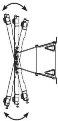
| Tilt Adjustment Range | ±15° (vertical), ±13° (horizontal) |
| Horizontal Leveling | ±10 mm / ±0.39 inches |
| Wall Material Compatibility | Concrete (recommended), wooden studs |
| Installation Tools Required | Phillips screwdriver, 8 mm wrench, leveler, drill, ∅8 mm drill bit (concrete) or ∅4 mm (wood) |
| Included Accessories | Wall mounting anchors (6), wall mounting screws (10), guide spacers A & B (4 each), guide spacer screws A & B (4 each), lock spring (2), wall mounting supporter screws (8), set protection cushion (4), VESA guide paper |
| Safety Features | Tilt movement adjustment screws, lock spring for secure attachment |
| Color | Black (typical) |
| Material | Steel |
| Certifications | Complies with safety standards (refer to manual) |
Frequently Asked Questions - OLW480B LG
User questions about OLW480B LG
0 question about this device. Answer the ones you know or ask your own.
Ask a new question about this device
Download the instructions for your Support pour écran plat in PDF format for free! Find your manual OLW480B - LG and take your electronic device back in hand. On this page are published all the documents necessary for the use of your device. OLW480B by LG.
USER MANUAL OLW480B LG
Installation Manual Wall Mounting Bracket
Please read the Safety Precautions carefully before using this product.
After reading this manual, keep it in an easily accessible location for future reference.
OLW480B

Accessories
Wall Mounting Anchor
6 EA
Wall Mounting Screw
10 EA
Installation Manual
Guide Spacer A
4 EA

Guide Spacer B
4 EA
Lock Spring 2EA
Guide Spacer Screw A
4 EA
(M6 x L45)
Guide Spacer Screw B
4 EA
(M6 x L18)

Wall mounting supporter screw
8 EA (M5 x L8)

Set Protection Cushion
4 EA
Wall mounting supporter VESA guide paper
(Australia)
VESA guide paper (North America, Japan)

Safety Precautions
- If you are a professional installer, please read this manual carefully before installing the product.
- After installing the product according to the manual, ensure that the user also reads the manual carefully and keeps it on hand. After reading the manual, please make sure the user keeps it in an easily accessible location for future reference.

Warning
The product should be installed by a professional installer designated by the retailer.
Installing the product without a professional installer is dangerous and may cause injury.
When moving or replacing the product after installation, contact a professional installer designated by the retailer. If an unqualified person moves or installs the product, safety hazards may arise.
Make sure you do not hang the power cable or signal cable on the back of your TV when installing the TV on the wall. The cables may be damaged, resulting in fire, electric shock, or damage to the product.
The product should be installed where its weight can be fully supported.
If the product is installed on a weak surface, it may fall, causing injury.
Do not hang on the product or subject it to impact after it is installed.
The product may fall and cause injury.

Caution
Follow the instructions in this Installation Manual to properly install the product.
If you do not follow the instructions in the Installation Manual the product may be installed incorrectly and cause serious injury or damage the product.
Check whether the wall is strong enough to hold the product before installation, and use the anchors and screws provided when installing.
If you use anchors or screws other than those specified by the manufacturer, they may not be able to hold the weight of the product, and this may cause safety hazards.
Do not clean the product with wet towels or place heaters or humidifiers underneath it.
Moisture entering the product or steam and heat may result in fire, electric shock, or damage to the product.
Remove the power cord from the outlet before installation.
Otherwise, it may cause electric shock or fire.
Make sure that you use the cable gender provided, as other cables may damage the product connector by causing friction between the product and the wall. (May vary by model.)
To install the product or adjust its height after installation, four or more people are needed.
If you try to handle the product alone, it may fall and cause injury or damage to the product.
When drilling holes in your walls, make sure you use a drill and drill bit with the specified diameter. Make sure that you also follow the instructions regarding the depth of the holes.
Otherwise, the product may be installed incorrectly and cause safety hazards.
Keep the product away from sprinklers, detectors, high-tension wires, power sources, or places where vibrations or shock from impact are likely to occur.
Wear work gloves when installing the product and do not use your bare hands.
Otherwise, this may cause injury.

Before Installation
* Do not use this product for purposes other than to install TVs on walls.
* Be careful when installing and using the wall mount to avoid product damage and safety hazards.
* You can easily install the wall mount by following the instructions in the Installation Manual.
* If the instructions in the manual are unclear, stop installing and contact a service center.
If you are still having problems understanding the instructions after contacting a service center, seek a professional installer to install the product for you.
* Individuals with mechanical or architectural experience may find it easier to understand this manual and install the product even if they are not professional installers.
* It is recommended that you install this product only on concrete walls. Issues that may arise due to installation on other materials (walls made of wood, plywood, bricks, etc.) will not be covered.
* Only install the product on vertical walls.
Do not install the product on walls at angles outside of the normal range, on severely slanted walls, or on the ceiling.
Issues that may occur as a result of installing the product on severely slanted walls or on the ceiling will not be covered.
* Check that the accessories provided with the product are all included before installing. Any damage to or loss of accessories after the inner packaging has been opened will not be covered.
* Make sure that the accessories are kept out of the reach of children to prevent safety hazards such as suffocation due to the swallowing of small parts.
* Make sure that all screws are fully tightened.
Applying excessive force to the screws may damage your wall, affect product performance, or cause damage to the product.
* Make sure that the installed TV does not exceed the specified tensile load and that no external force is applied to it.
* To prevent any safety hazards, take care when handling tools during the installation.
Phillips screwdriver (manual or electric), 8 mm wrench, leveler, drill, ∅ 8 mm drill bit for concrete or ∅ 4 mm drill bit for steel

Installation Instructions
- The images may differ from the actual product.
— Please consult a professional when installing the wall mount.
1 Attaching the Guide Spacers
- If the screws cannot be fully tightened on the guide spacers, check the length of the screws.
VESA Size 300x300 Model VESA Size 400x200, 300x200 Models
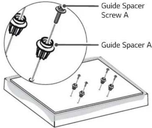
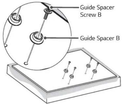
Instructions
- Remove any screws that are already fastened to the parts to be attached to the wall mount.
-
Fix the guide spacers and the guide spacer screws in order as shown in the image.
-
Place the product on a table with the screen facing down. Make sure that you place it on a flat surface with a soft cloth or a cushion to protect the screen.
- Fix the guide spacer to the set with the screws. Tighten the screws until the set, the guide spacers, and the screws are securely attached.
- Use a Phillips screwdriver (manual or electric) to tighten the screws.
2
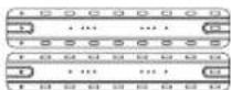
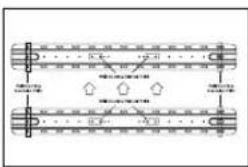
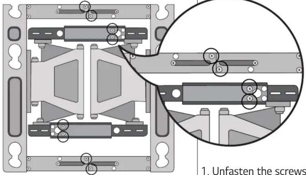
Adjusting the Length of the Wall Mounting Bracket (VESA Size 400x200 Models Only)
natural_image
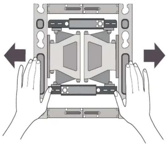
Illustration of hands assembling a mechanical component with directional arrows indicating assembly (no text or symbols)-
Unfasten the screws (at 8 points).
-
Hold the wall mounting bracket and pull on both sides.
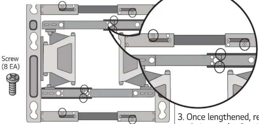
- Once lengthened, refasten the screws to their parts (at 8 points).
3
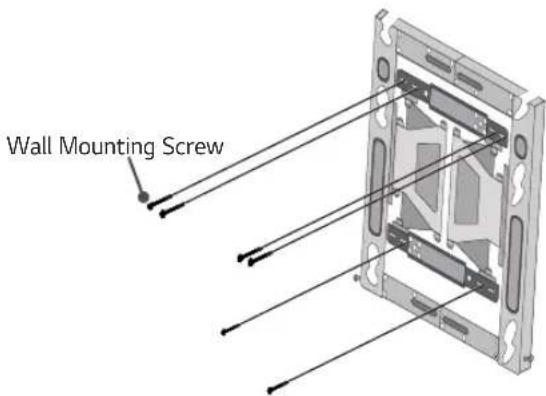
Fixing the Anchors and Screws in Place
Please follow the instructions below.
— Check the wall material and the thickness of the finish.
- You can use the included anchors and screws only when the wall is made of concrete that will not crack.
- Do not install the device on wood studs, plaster boards, or walls made with medium-density fiberboard (MDF). If installing on such materials, the anchor screws must be fixed on the concrete behind the finish. If there is no concrete on the other side, then you must first install a separate hanger to which the anchors and screws can be fixed.
- When installing the product on a type of wall not specified in this manual, make sure each fixed point can withstand a pullout load of at least 70 kgf (154 lbf, 686 N) and a shear load of at least 100 kgf (220.5 lbf, 980 N).
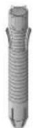
Wall Mounting Anchor

natural_image
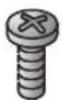
Close-up of a threaded screw with visible teeth and central bore (no text or symbols)
natural_image
Simple geometric diagram with two adjacent rectangles, one gray and one white, separated by a vertical line (no text or symbols)
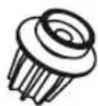
natural_image
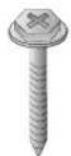
Pure mechanical diagram showing a threaded component with a pin and base, no text or symbols presentWall Mounting Screw

natural_image
Close-up of a threaded mechanical component with a metallic end, shown in close-up (no text or symbols visible)
natural_image
Mechanical assembly diagram showing a threaded component inserted into a housing with an arrow indicating direction (no text or labels)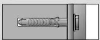
natural_image
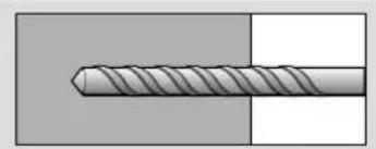
Technical diagram of a threaded fastener inserted into a housing (no text or symbols)- Use an ∅ 8 mm drill bit for concrete and a hammer (impact) drill.
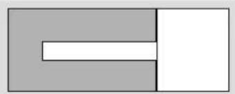
a. Drill a hole 80–100 mm(3.15 - 3.94 Inches) deep using an ∅ 8 mm drill bit where the anchor will be fixed.
b. Clean out the drilled hole.
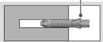
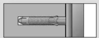
c. Insert the provided wall mounting anchor into the hole. (Use a hammer to insert the anchor.)
d. Place the wall mounting bracket against the wall and align it with the holes. Make sure that the tilt adjustment part faces upward.
e. Insert the wall mounting screws into the holes and tighten them. Tighten the screws with a torque between 45 kgf/cm (39 lbf/in) and 60 kgf/cm (52 lbf/in) or more.
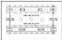
4 How to install the wall mounting bracket (North America, Japan)
- Check the wall type before mounting.
- When mounting on a wooden wall, check the screw fixing spots on the wall according to the Wall Mounting Supporter Point.
- Mark the wall mounting location using the VESA guide paper provided.
- Marking the Screw Fixing Spots on the Wall Using the VESA Guide Paper.
When mounting to wooden stud (VESA Size 300x300, 300x200)
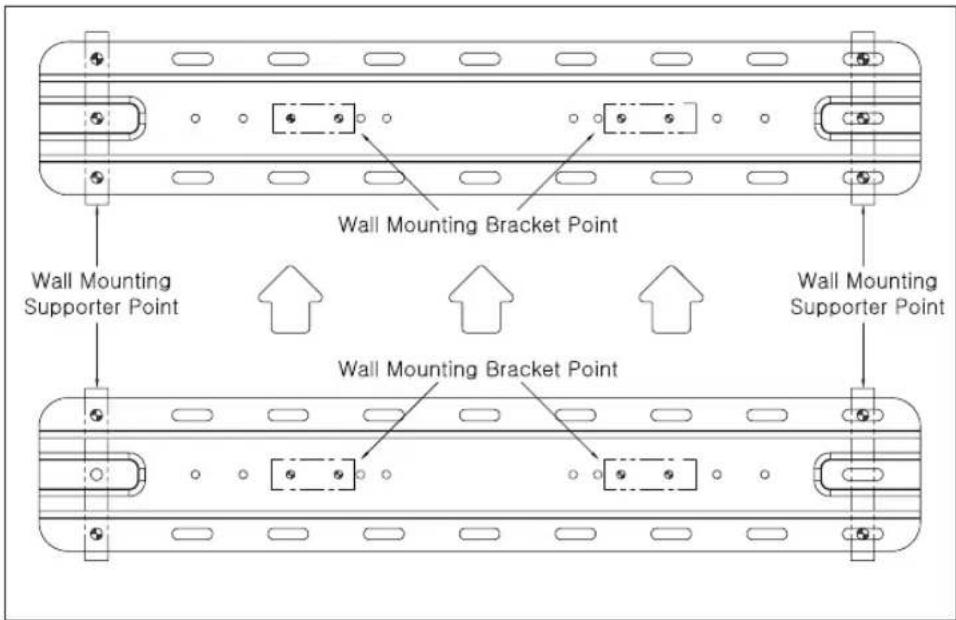
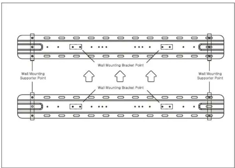
When mounting to wooden stud (VESA Size 400X200)
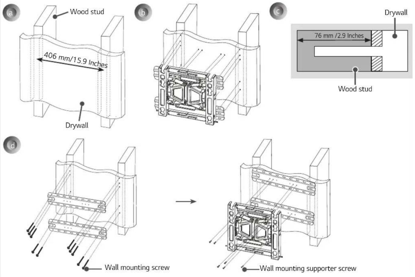
a. Locate and mark the centers of the wall studs using a stud finder.
b. After aligning the wall mounting bracket on the wall where the center of the wood stud is marked, mark the location of the screws and then remove the wall mounting bracket. (Use a level to make sure your screw marks are level.)
c. Use the ∅ 4 mm drill bit for wood to drill holes with the depth of 76 mm(2.9 Inches) or above where the wall mounting screw location is marked on the wall. (Clean the drilled hole.)
d. Tighten the wall mounting screws for the wall bracket on the drilled hole.
→ At this time, tighten the screw so that the wall, wall mounting bracket and the wall mounting screw are pressed against one another. (Drywall can be damaged when tightened with excessive force, please be careful.)
→ When tightening the screw use the + driver (manual or motorized) or 8 mm wrench.
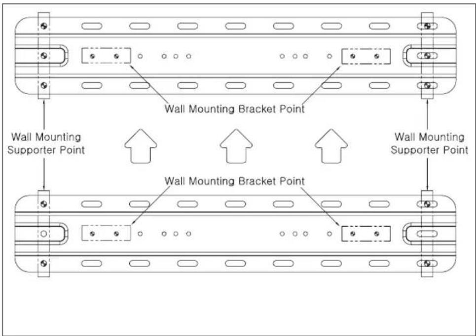
5 How to install the wall mounting bracket (Australia)
- Check the wall type before mounting.
- When mounting on a wooden wall, check the screw fixing spots on the wall according to the Wall Mounting Supporter Point.
- Mark the wall mounting location using the VESA guide paper provided.
- Marking the Screw Fixing Spots on the Wall Using the VESA Guide Paper.
When mounting to wooden stud (VESA Size 300x300, 300x200)
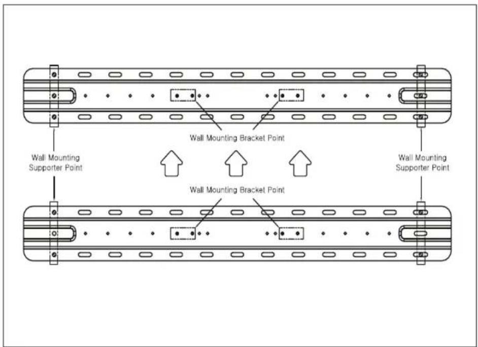
When mounting to wooden stud (VESA Size 400X200)
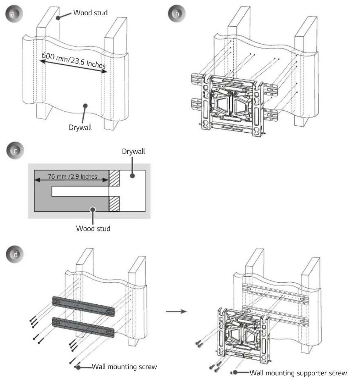
a. Locate and mark the centers of the wall studs using a stud finder.
b. After aligning the wall mounting bracket on the wall where the center of the wood stud is marked, mark the location of the screws and then remove the wall mounting bracket. (Use a level to make sure your screw marks are level.)
c. Use the ∅ 4 mm drill bit for wood to drill holes with the depth of 76 mm(2.9 Inches) or above where the wall mounting screw location is marked on the wall. (Clean the drilled hole.)
d. Tighten the wall mounting screws for the wall bracket on the drilled hole.
→ At this time, tighten the screw so that the wall, wall mounting bracket and the wall mounting screw are pressed against one another. (Drywall can be damaged when tightened with excessive force, please be careful.)
→ When tightening the screw use the + driver (manual or motorized) or 8 mm wrench.
6 Installing the Wall Mounting Bracket
- It is recommended that you install this product only on concrete walls. Issues that may arise due to installation on other materials (walls made of wood, plywood, bricks, etc.) will not be covered.
→ Position the wall mounting bracket in the desired spot, mark the screw holes, and remove the bracket.
→ Refer to the image below on how to fix the wall mounting bracket in place.
→ Use a leveler to check whether the wall mount is level.
→ If you are unable to tighten the screws in their specified points, you can fasten them in other adjacent points. However, do not change the locations of two or more points.
→ Fix two wall mounting screws in the upper left and two wall mounting screws in the upper right. Fix one screw in the lower left and one screw in the lower right.
→ Use a Phillips screwdriver (manual or electric) or an 8 mm wrench on the screws so that the wall mounting bracket completely touches the wall.
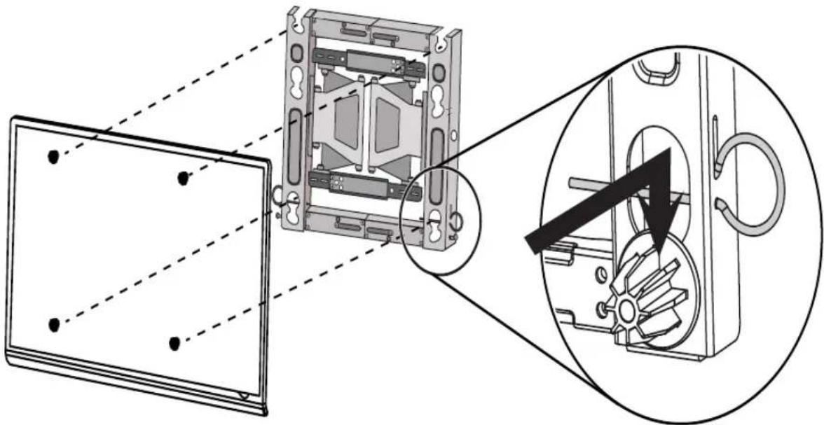
7 Attaching the TV to the Wall Mounting Bracket
— Two or more people are needed to lift the product.
natural_image
Technical diagram showing a device with internal components and a magnified view of the internal structure (no text or symbols present)* Caution: Make sure that the power cord does not get trapped between the wall mounting bracket and the set during installation.
(A trapped power cord may cause damage to the product.)
→ Place the product on the wall in the direction of the arrow with the guide spacers in the wall mounting bracket. Attach the lower part first, then attach the upper part by slightly lifting up the set.
- Make sure that the product is fixed securely in place by pulling on the bottom of the set.
- If speakers have been attached to the product, lift it by holding the product itself, not the speakers.
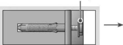
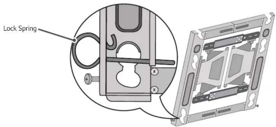
8 Fixing the Lock Spring
* Caution: If it is not fixed securely, the set may fall off, resulting in damage or injury.
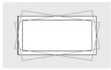
9 Leveling the Product
- If the product is not level after installation, adjust it using the screws. (The product goes up or down depending on the direction the screws are turned.)
natural_image
Abstract geometric diagram with overlapping rectangles and dashed lines (no text or symbols)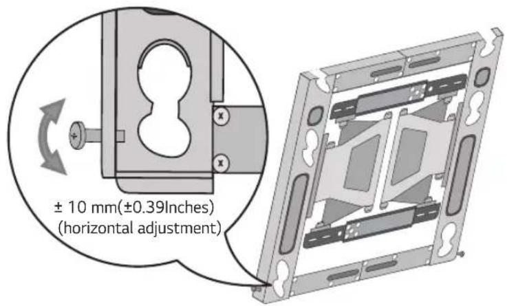
10 Organizing the Cables and Attaching the Set Protection Cushion
- Organize the cables as shown in the image. You should use cable organizer bands purchased separately or use those provided with your TV.
- Attach the set protection cushion to reduce the shock received by the set as it bumps into the wall when tilting. Attach it to the desired location as shown in the image.
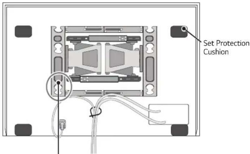
* Caution: Make sure that the power cord or cables do not get trapped between the wall mount and the wall as this may damage the cables.
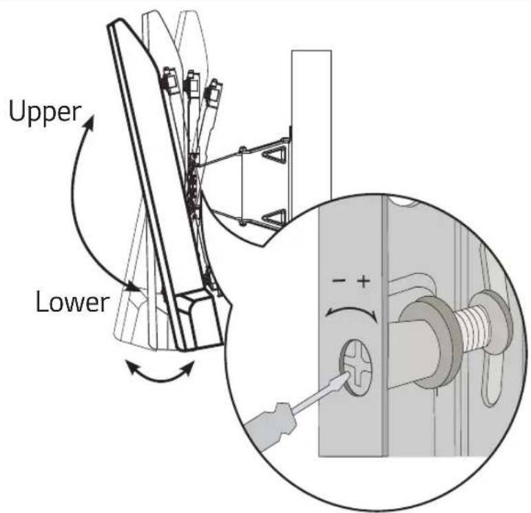
11 Adjusting the Tilt Movement Strength
- If your TV is not fixed in the up/down direction and keeps moving, turn the left/right adjusting screw in the direction of "+" turning it for "1/4 of a turn" (6-click sounds). (The wall mount will be fixed.)
- In contrast, if your TV is stiff in the up/down direction when moving, turn the left/right adjusting screw in the direction of "-" , turning it for "1/4 of a turn" (6-click sounds). (The wall mount will easily move.)
* Initial state setting method
a. Turn the left/right adjusting screw all the way in the "+" direction.
b. Turn both left/right adjusting screws half way in the "-" direction, (12-click sounds).
c. Once 'a' and 'b' steps are completed, they are returned to the initial shipment status.
* Caution: Excessive adjustment of the adjusting screws in the "+" and "-" direction may damage the TV and/or the wall mount.

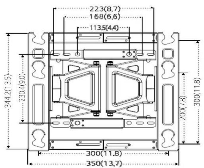
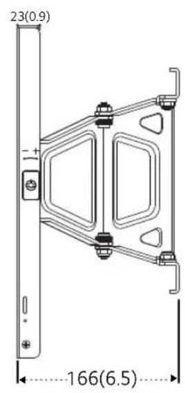
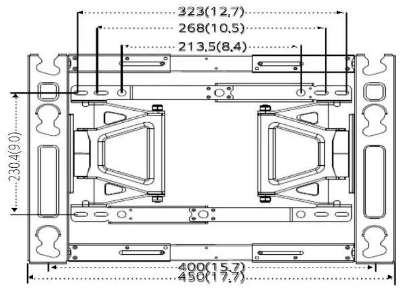
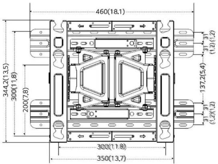
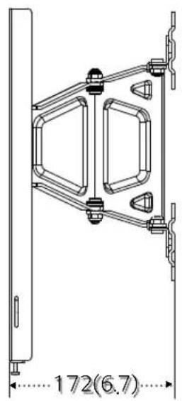
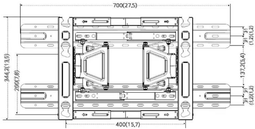
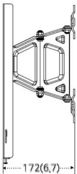
Product Specifications
natural_image
Pure mechanical diagram showing intersecting rods and a triangular frame with rotational arrows (no text or symbols)13 ± 2^
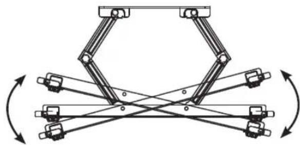
natural_image
Mechanical linkage diagram showing multiple articulated joints with rotational arrows indicating motion (no text or symbols)15 ± 2^
[300 × 300]
[400 × 200]
North America, Japan
[ Unit: mm(Inches)]
[300 × 300]
[400 × 200]
Australia
[Unit: mm(Inches)]
[300×300]
[400×200]
| Model name OLW480B | |
| Width (mm/Inches) 350/ | 13.7 (standard) /450/17.7 (lengthened) |
| Height (mm/Inches) 345/ | 13.5 |
| Depth (mm/Inches) 23/0.9 | |
| Product weight (kg/lbs) 3.7/8.1 | |
| Wall mounting bracketVESA specifications(mm/Inches) | Standard : 300x300 /11.8X11.8,300x200 /11.8X7.8Lengthened: 400x200 /15.7X7.8 |
| Max. tensile load (kg/lbs) 50/110 | |
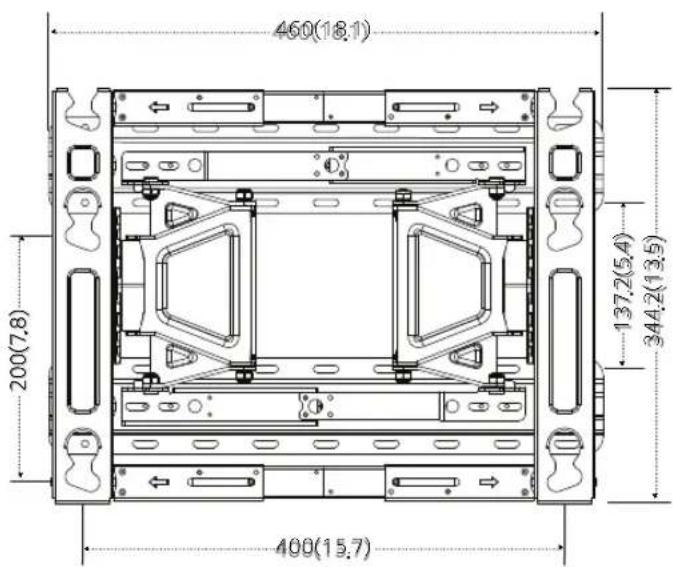
North America, Japan
| Model name OLW480B Model name OLW480B | |
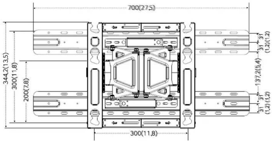
| Width (mm/Inches) 460/18.1 Width (mm/Inches) 700/27.5 | |
| Height (mm/Inches) 345/13.5 Height (mm/Inches) 345/13.5 | |
| Depth (mm/Inches) 29/1.1 Depth (mm/Inches) 29/1.1 | |
| Product weight (kg/lbs) 5.4/11.9 Product weight (kg/lbs) 6.2/13 | |
| Wall mounting bracket VESA specifications (mm/Inches) | Standard : 300x300 /11.8X11.8, 300x200 /11.8X7.8 Lengthened: 400x200 /15.7X7.8 |
| Max. tensile load (kg/lbs) 50/110 Max. tensile load (kg/lbs) 50/11 | |
Australia
| Wall mounting bracket VESA specifications (mm/Inches) | Standard: 300x300 /11.8X11.8, 300x200 /11.8X7.8 Lengthened: 400x200/15.7X7.8 |

LG
Life's Good
The model and serial number of the product is located on the back or one side of the product. Record it below should you ever need service.
MODEL
SERIAL
Supported Displays
(Please contact the retailers or refer to the TV owner's manual for applicable models.)
- Installation Manual Wall Mounting Bracket
- Accessories
- Safety Precautions
- Warning
- The product should be installed by a professional installer designated by the retailer.
- The product should be installed where its weight can be fully supported.
- Do not hang on the product or subject it to impact after it is installed.
- Caution
- Follow the instructions in this Installation Manual to properly install the product.
- Check whether the wall is strong enough to hold the product before installation, and use the anchors and screws provided when installing.
- Do not clean the product with wet towels or place heaters or humidifiers underneath it.
- Remove the power cord from the outlet before installation.
- To install the product or adjust its height after installation, four or more people are needed.
- When drilling holes in your walls, make sure you use a drill and drill bit with the specified diameter. Make sure that you also follow the instructions regarding the depth of the holes.
- Keep the product away from sprinklers, detectors, high-tension wires, power sources, or places where vibrations or shock from impact are likely to occur.
- Wear work gloves when installing the product and do not use your bare hands.
- Before Installation
- Installation Instructions
- Attaching the Guide Spacers
- Instructions
- 2
- Adjusting the Length of the Wall Mounting Bracket (VESA Size 400x200 Models Only)
- 3
- Fixing the Anchors and Screws in Place
- Please follow the instructions below.
- How to install the wall mounting bracket (North America, Japan)
- How to install the wall mounting bracket (Australia)
- Installing the Wall Mounting Bracket
- Attaching the TV to the Wall Mounting Bracket
- Fixing the Lock Spring
- Leveling the Product
- Organizing the Cables and Attaching the Set Protection Cushion
- Adjusting the Tilt Movement Strength
- Product Specifications
- North America, Japan
- Australia
- Supported Displays
Brand : LG
Model : OLW480B
Category : Support pour écran plat